JP2010023588A - Power output device, vehicle mounted thereon, and control method of motive power output device - Google Patents
Power output device, vehicle mounted thereon, and control method of motive power output device Download PDFInfo
- Publication number
- JP2010023588A JP2010023588A JP2008185213A JP2008185213A JP2010023588A JP 2010023588 A JP2010023588 A JP 2010023588A JP 2008185213 A JP2008185213 A JP 2008185213A JP 2008185213 A JP2008185213 A JP 2008185213A JP 2010023588 A JP2010023588 A JP 2010023588A
- Authority
- JP
- Japan
- Prior art keywords
- power
- internal combustion
- engine
- combustion engine
- rotational speed
- Prior art date
- Legal status (The legal status is an assumption and is not a legal conclusion. Google has not performed a legal analysis and makes no representation as to the accuracy of the status listed.)
- Pending
Links
Images


Classifications
-
- Y—GENERAL TAGGING OF NEW TECHNOLOGICAL DEVELOPMENTS; GENERAL TAGGING OF CROSS-SECTIONAL TECHNOLOGIES SPANNING OVER SEVERAL SECTIONS OF THE IPC; TECHNICAL SUBJECTS COVERED BY FORMER USPC CROSS-REFERENCE ART COLLECTIONS [XRACs] AND DIGESTS
- Y02—TECHNOLOGIES OR APPLICATIONS FOR MITIGATION OR ADAPTATION AGAINST CLIMATE CHANGE
- Y02T—CLIMATE CHANGE MITIGATION TECHNOLOGIES RELATED TO TRANSPORTATION
- Y02T10/00—Road transport of goods or passengers
- Y02T10/60—Other road transportation technologies with climate change mitigation effect
- Y02T10/62—Hybrid vehicles
-
- Y—GENERAL TAGGING OF NEW TECHNOLOGICAL DEVELOPMENTS; GENERAL TAGGING OF CROSS-SECTIONAL TECHNOLOGIES SPANNING OVER SEVERAL SECTIONS OF THE IPC; TECHNICAL SUBJECTS COVERED BY FORMER USPC CROSS-REFERENCE ART COLLECTIONS [XRACs] AND DIGESTS
- Y02—TECHNOLOGIES OR APPLICATIONS FOR MITIGATION OR ADAPTATION AGAINST CLIMATE CHANGE
- Y02T—CLIMATE CHANGE MITIGATION TECHNOLOGIES RELATED TO TRANSPORTATION
- Y02T10/00—Road transport of goods or passengers
- Y02T10/60—Other road transportation technologies with climate change mitigation effect
- Y02T10/64—Electric machine technologies in electromobility
Landscapes
- Hybrid Electric Vehicles (AREA)
- Control Of Vehicle Engines Or Engines For Specific Uses (AREA)
- Electric Propulsion And Braking For Vehicles (AREA)
Abstract
【課題】二次電池などの蓄電装置の温度が高くなったときにおける蓄電装置の充放電を抑制することにより蓄電装置の劣化を抑制する。
【解決手段】電池温度Tbが閾値以上の高温時にエンジン回転数を増加するときには、低温時に用いられる回転数変化量より大きい変化量を上限上昇率ΔNとして用いてエンジン回転数が目標回転数Ne*に向けて増加するよう実行用回転数Netagを設定し(S150,S160)、実行用回転数Netagでエンジンが運転されると共に要求トルクTr*が駆動軸に出力されるようモータMG1,MG2のトルク指令Tm1*,Tm2*を設定する(S170〜S200)。これにより、エンジン回転数を迅速に上昇させ、エンジンパワーでは不足するパワーを出力するためにバッテリから放電される電力を小さくすることができ、バッテリの充放電を抑制することができる。
【選択図】図4Deterioration of a power storage device is suppressed by suppressing charging / discharging of the power storage device when the temperature of the power storage device such as a secondary battery becomes high.
When the engine speed is increased when the battery temperature Tb is higher than a threshold, the engine speed is set to the target speed Ne * by using a change amount larger than the engine speed change amount used at a low temperature as the upper limit increase rate ΔN. Is set so as to increase toward the engine speed (S150, S160), and the engine is operated at the execution speed Nettag and the torques of the motors MG1, MG2 are output to the drive shaft while the required torque Tr * is output. Commands Tm1 * and Tm2 * are set (S170 to S200). As a result, the engine speed can be increased quickly, the power discharged from the battery can be reduced in order to output power that is insufficient with engine power, and charging / discharging of the battery can be suppressed.
[Selection] Figure 4
Description
本発明は、動力出力装置およびこれを搭載する車両並びに動力出力装置の制御方法に関する。 The present invention relates to a power output apparatus, a vehicle on which the power output apparatus is mounted, and a method for controlling the power output apparatus.
従来、この種の動力出力装置としては、バッテリの出力制限が大きく制限されるほど小さくなる傾向にエンジンの回転数の上限上昇率を設定し、この設定した上限上昇率の範囲内でエンジンの回転数を上昇させるものが提案されている(例えば、特許文献1参照)。この装置では、こうした制御により出力応答性の低下を抑制し、運転者にモタツキ感を与えるのを抑制している。
上述の動力出力装置では、バッテリが高温のときにはバッテリの劣化が促進されてしまう場合がある。バッテリが高温になることによってバッテリの出力制限が大きく制限されたときに駆動軸に要求される要求駆動力が急増して必要なパワーが急増すると、エンジンの回転数の上限上昇率が大きく制限されるため、エンジンから出力するパワーを急増させることができない結果、必要なパワーのうちエンジンから出力するパワーでは賄うことができない分、即ちバッテリからの放電により賄う分が大きくなる。このため、バッテリの充放電が多くなり、バッテリの温度が更に上昇しやすくなり、場合によってはバッテリの劣化が促進されてしまう。 In the above-described power output apparatus, when the battery is hot, the battery deterioration may be promoted. If the required drive force required for the drive shaft suddenly increases when the battery output limit is greatly limited due to the high temperature of the battery, and the required power increases rapidly, the upper limit increase rate of the engine speed is greatly limited. As a result, the power output from the engine cannot be increased rapidly. As a result, the amount of necessary power that cannot be covered by the power output from the engine, that is, the amount covered by the discharge from the battery increases. For this reason, charging / discharging of a battery increases, the temperature of a battery tends to rise further, and deterioration of a battery will be accelerated | stimulated depending on the case.
本発明の動力出力装置およびこれを搭載する車両並びに動力出力装置の制御方法は、二次電池などの蓄電装置の温度が高くなったときにおける蓄電装置の充放電を抑制することにより蓄電装置の劣化を抑制することを主目的とする。 The power output device of the present invention, a vehicle equipped with the power output device, and a method for controlling the power output device are provided with a power storage device deterioration by suppressing charging / discharging of the power storage device when the temperature of the power storage device such as a secondary battery becomes high. The main purpose is to suppress this.
本発明の動力出力装置およびこれを搭載する車両並びに動力出力装置の制御方法は、上述の主目的を達成するために以下の手段を採った。 The power output apparatus of the present invention, the vehicle equipped with the power output apparatus, and the control method of the power output apparatus employ the following means in order to achieve the main object described above.
本発明の動力出力装置は、
駆動軸に動力を出力する動力出力装置であって、
前記駆動軸に動力を出力する内燃機関と、
動力の入出力が可能で前記内燃機関からの動力の一部を用いて発電する発電機と、
前記駆動軸に動力を出力する電動機と、
前記発電機および前記電動機と電力のやりとりが可能で所定温度以上の高温領域で充放電してもよい最大電力の絶対値が小さくなる性能を有する蓄電手段と、
前記蓄電手段の温度を検出する温度検出手段と、
前記駆動軸に要求される要求駆動力を設定する要求駆動力設定手段と、
前記設定された要求駆動力と所定の制約とに基づいて前記内燃機関の目標回転数と目標トルクからなる目標運転ポイントを設定する目標運転ポイント設定手段と、
前記検出された前記蓄電手段の温度が前記所定温度より低い閾値温度未満のときには前記内燃機関の回転数が第1の回転数上昇程度の範囲内で前記設定された目標回転数に向けて変化しながら前記設定された要求駆動力に基づく駆動力が前記駆動軸に出力されるよう前記内燃機関と前記発電機と前記電動機とを制御し、前記検出された前記蓄電手段の温度が前記閾値温度以上のときには前記内燃機関の回転数が前記第1の回転数上昇程度より大きい第2の回転数上昇程度の範囲内で前記設定された目標回転数に向けて変化しながら前記設定された要求駆動力に基づく駆動力が前記駆動軸に出力されるよう前記内燃機関と前記発電機と前記電動機とを制御する制御手段と、
を備えることを要旨とする。
The power output apparatus of the present invention is
A power output device that outputs power to a drive shaft,
An internal combustion engine that outputs power to the drive shaft;
A generator capable of inputting and outputting power and generating electric power using a part of the power from the internal combustion engine;
An electric motor that outputs power to the drive shaft;
Electric power storage means capable of exchanging electric power with the generator and the electric motor and having the performance of reducing the absolute value of the maximum electric power that may be charged and discharged in a high temperature region above a predetermined temperature;
Temperature detecting means for detecting the temperature of the power storage means;
Required driving force setting means for setting required driving force required for the drive shaft;
Target operating point setting means for setting a target operating point comprising a target rotational speed and a target torque of the internal combustion engine based on the set required driving force and a predetermined constraint;
When the detected temperature of the power storage means is lower than a threshold temperature lower than the predetermined temperature, the rotational speed of the internal combustion engine changes toward the set target rotational speed within a range of the first rotational speed increase. However, the internal combustion engine, the generator, and the electric motor are controlled such that a driving force based on the set required driving force is output to the driving shaft, and the detected temperature of the power storage means is equal to or higher than the threshold temperature. In this case, the set required driving force while the engine speed changes toward the set target engine speed within a range of the second engine speed increase that is greater than the first engine speed increase. Control means for controlling the internal combustion engine, the generator, and the electric motor so that a driving force based on the output is output to the drive shaft;
It is a summary to provide.
この本発明の動力出力装置では、駆動軸に要求された要求駆動力と所定の制約とに基づいて内燃機関の目標回転数と目標トルクからなる目標運転ポイントを設定する。そして、所定温度以上の高温領域で充放電してもよい最大電力の絶対値が小さくなる性能を有する蓄電手段の温度が所定温度より低い閾値温度未満のときには内燃機関の回転数が第1の回転数上昇程度の範囲内で設定した目標回転数に向けて変化しながら要求駆動力に基づく駆動力が駆動軸に出力されるよう内燃機関と発電機と電動機とを制御し、蓄電手段の温度が閾値温度以上のときには内燃機関の回転数が第1の回転数上昇程度より大きい第2の回転数上昇程度の範囲内で設定した目標回転数に向けて変化しながら要求駆動力に基づく駆動力が駆動軸に出力されるよう内燃機関と発電機と電動機とを制御する。このように蓄電手段の温度が閾値温度以上のときには内燃機関の回転数が第1の回転数上昇程度より大きい第2の回転数上昇程度の範囲内で設定した目標回転数に向けて変化するから、蓄電手段の温度が閾値温度未満のときに比して、内燃機関の回転数を迅速に上昇させることができ、内燃機関からより大きなパワーを出力することができる。したがって、駆動軸に出力すべきパワーのうち内燃機関から出力するパワーでは賄うことができない分を小さくすることができ、蓄電手段からの放電電力を小さくすることができる。この結果、蓄電手段の温度が閾値温度以上のときに蓄電手段の充放電を抑制することができ、これにより蓄電手段の劣化を抑制することができる。 In the power output apparatus of the present invention, a target operating point consisting of a target rotational speed and a target torque of the internal combustion engine is set based on the required driving force required for the drive shaft and predetermined constraints. When the temperature of the power storage means having the performance of reducing the absolute value of the maximum power that can be charged / discharged in a high temperature region equal to or higher than the predetermined temperature is lower than the threshold temperature lower than the predetermined temperature, the rotational speed of the internal combustion engine is the first rotation. The internal combustion engine, the generator, and the electric motor are controlled so that the driving force based on the required driving force is output to the drive shaft while changing toward the target rotational speed set within a range of several rises, and the temperature of the power storage means is When the temperature is equal to or higher than the threshold temperature, the driving force based on the required driving force changes while changing toward the target rotational speed set within the range of the second rotational speed increase that is greater than the first rotational speed increase. The internal combustion engine, the generator, and the electric motor are controlled so as to be output to the drive shaft. Thus, when the temperature of the power storage means is equal to or higher than the threshold temperature, the rotational speed of the internal combustion engine changes toward the target rotational speed set within a range of the second rotational speed increase that is larger than the first rotational speed increase. As compared with the case where the temperature of the power storage means is lower than the threshold temperature, the number of revolutions of the internal combustion engine can be increased rapidly, and larger power can be output from the internal combustion engine. Therefore, it is possible to reduce the amount of power to be output to the drive shaft that cannot be covered by the power output from the internal combustion engine, and it is possible to reduce the discharge power from the power storage means. As a result, when the temperature of the power storage means is equal to or higher than the threshold temperature, charging / discharging of the power storage means can be suppressed, and thereby deterioration of the power storage means can be suppressed.
こうした本発明の動力出力装置において、前記第2の回転数上昇程度は、前記検出された前記蓄電手段の温度が高いほど大きくなる傾向に設定されてなるものとすることもできる。こうすれば、蓄電手段の温度に応じて蓄電手段の充放電を抑制することができる。 In such a power output apparatus of the present invention, the second rotational speed increase degree may be set so as to increase as the detected temperature of the power storage means increases. If it carries out like this, charging / discharging of an electrical storage means can be suppressed according to the temperature of an electrical storage means.
また、本発明の動力出力装置において、前記第2の回転数上昇程度は、前記内燃機関の回転に伴って回転する部品の耐久性により得られる許容最大回転数上昇量以下の範囲で設定されてなるものとすることもできる。こうすれば、内燃機関の回転に伴って回転する部品の破損を抑制することができる。 In the power output apparatus of the present invention, the second rotational speed increase degree is set within a range equal to or less than an allowable maximum rotational speed increase amount obtained by durability of a component that rotates as the internal combustion engine rotates. It can also be. By so doing, it is possible to suppress damage to components that rotate as the internal combustion engine rotates.
さらに、本発明の動力出力装置において、前記制御手段は、前記検出された前記蓄電手段の温度が前記閾値温度未満のときに前記内燃機関の回転数を上昇させるときには、前記内燃機関の回転数に前記第1の回転数上昇程度の上昇を考慮した回転数と前記目標回転数とのうちの小さい方の回転数を実行用回転数として用いて前記内燃機関が前記実行用回転数で回転すると共に前記設定された要求駆動力に基づく駆動力が前記駆動軸に出力されるよう前記内燃機関と前記発電機と前記電動機とを制御し、前記検出された前記蓄電手段の温度が前記閾値温度以上のときに前記内燃機関の回転数を上昇させるときには前記内燃機関の回転数に前記第2の回転数上昇程度の上昇を考慮した回転数と前記目標回転数とのうちの小さい方の回転数を実行用回転数として用いて前記内燃機関が前記実行用回転数で回転すると共に前記設定された要求駆動力に基づく駆動力が前記駆動軸に出力されるよう前記内燃機関と前記発電機と前記電動機とを制御する手段であるものとすることもできる。 Further, in the power output apparatus according to the present invention, the control means may increase the rotational speed of the internal combustion engine when increasing the rotational speed of the internal combustion engine when the detected temperature of the power storage means is lower than the threshold temperature. The internal combustion engine rotates at the execution speed using the smaller one of the rotation speed considering the increase of the first rotation speed and the target rotation speed as the execution speed. The internal combustion engine, the generator, and the electric motor are controlled so that a driving force based on the set required driving force is output to the drive shaft, and the detected temperature of the power storage means is equal to or higher than the threshold temperature. Sometimes when increasing the rotational speed of the internal combustion engine, the rotational speed of the internal combustion engine which is smaller of the rotational speed considering the increase of the second rotational speed increase and the target rotational speed is executed. for The internal combustion engine, the generator, and the motor are used so that the internal combustion engine rotates at the execution rotational speed and is output to the drive shaft based on the set required drive force. It can also be a means for controlling.
あるいは、本発明の動力出力装置において、前記駆動軸と前記内燃機関の出力軸と前記発電機の回転軸との3軸に接続され、該3軸のうちのいずれか2軸に入出力される動力に基づいて残余の軸に動力を入出力する3軸式動力入出力手段を備えるものとすることもできる。 Alternatively, in the power output apparatus of the present invention, the drive shaft, the output shaft of the internal combustion engine, and the rotating shaft of the generator are connected to three axes, and input / output is performed on any two of the three axes. A three-axis power input / output means for inputting / outputting power to the remaining shafts based on the power may be provided.
本発明の車両は、上述のいずれかの態様の本発明の動力出力装置、即ち、基本的には、駆動軸に動力を出力する動力出力装置であって、前記駆動軸に動力を出力する内燃機関と、動力の入出力が可能で前記内燃機関からの動力の一部を用いて発電する発電機と、前記駆動軸に動力を出力する電動機と、前記発電機および前記電動機と電力のやりとりが可能で所定温度以上の高温領域で充放電してもよい最大電力の絶対値が小さくなる性能を有する蓄電手段と、前記蓄電手段の温度を検出する温度検出手段と、前記駆動軸に要求される要求駆動力を設定する要求駆動力設定手段と、前記設定された要求駆動力と所定の制約とに基づいて前記内燃機関の目標回転数と目標トルクからなる目標運転ポイントを設定する目標運転ポイント設定手段と、前記検出された前記蓄電手段の温度が前記所定温度より低い閾値温度未満のときには前記内燃機関の回転数が第1の回転数上昇程度の範囲内で前記設定された目標回転数に向けて変化しながら前記設定された要求駆動力に基づく駆動力が前記駆動軸に出力されるよう前記内燃機関と前記発電機と前記電動機とを制御し、前記検出された前記蓄電手段の温度が前記閾値温度以上のときには前記内燃機関の回転数が前記第1の回転数上昇程度より大きい第2の回転数上昇程度の範囲内で前記設定された目標回転数に向けて変化しながら前記設定された要求駆動力に基づく駆動力が前記駆動軸に出力されるよう前記内燃機関と前記発電機と前記電動機とを制御する制御手段と、を備える動力出力装置を搭載し、車軸が前記駆動軸に連結されてなることを要旨とする。 The vehicle of the present invention is a power output device of the present invention according to any one of the above-described aspects, that is, basically a power output device that outputs power to a drive shaft, and an internal combustion engine that outputs power to the drive shaft. An engine, a generator capable of inputting / outputting power and generating electric power using a part of the power from the internal combustion engine, an electric motor outputting power to the drive shaft, and exchange of electric power with the generator and the electric motor Power storage means capable of reducing the absolute value of the maximum power that can be charged and discharged in a high temperature region above a predetermined temperature, temperature detection means for detecting the temperature of the power storage means, and the drive shaft are required A required driving force setting means for setting a required driving force, and a target operating point setting for setting a target operating point consisting of a target rotational speed and a target torque of the internal combustion engine based on the set required driving force and a predetermined constraint Means, When the detected temperature of the power storage means is lower than the threshold temperature lower than the predetermined temperature, the rotational speed of the internal combustion engine changes toward the set target rotational speed within a range of about the first rotational speed increase. However, the internal combustion engine, the generator, and the electric motor are controlled such that a driving force based on the set required driving force is output to the driving shaft, and the detected temperature of the power storage means is equal to or higher than the threshold temperature. In this case, the set required driving force while the engine speed changes toward the set target engine speed within a range of the second engine speed increase that is greater than the first engine speed increase. A power output device including a control means for controlling the internal combustion engine, the generator, and the electric motor so that a driving force based on the power is output to the drive shaft, and an axle is connected to the drive shaft This The the gist.
この本発明の車両では、上述のいずれかの態様の本発明の動力出力装置を搭載するから、本発明の動力出力装置が奏する効果、例えば、駆動軸に出力すべきパワーのうち内燃機関から出力するパワーでは賄うことができない分を小さくして蓄電手段からの放電電力を小さくすることができる効果や、この結果、蓄電手段の温度が閾値温度以上のときに蓄電手段の充放電を抑制して蓄電手段の劣化を抑制することができる効果などと同様の効果を奏することができる。 Since the vehicle according to the present invention is equipped with the power output device of the present invention according to any one of the above-described aspects, the effect produced by the power output device of the present invention, for example, output from the internal combustion engine out of the power to be output to the drive shaft. The effect of reducing the amount of power that cannot be covered by the power to reduce the discharge power from the power storage means, and as a result, suppressing the charge / discharge of the power storage means when the temperature of the power storage means is equal to or higher than the threshold temperature. The same effect as the effect of suppressing the deterioration of the power storage means can be obtained.
本発明の動力出力装置の制御方法は、
駆動軸に動力を出力する内燃機関と、動力の入出力が可能で前記内燃機関からの動力の一部を用いて発電する発電機と、前記駆動軸に動力を出力する電動機と、前記発電機および前記電動機と電力のやりとりが可能で所定温度以上の高温領域で充放電してもよい最大電力の絶対値が小さくなる性能を有する蓄電手段と、を備える動力出力装置の制御方法であって、
前記駆動軸に要求された要求駆動力と所定の制約とに基づいて前記内燃機関の目標回転数と目標トルクからなる目標運転ポイントを設定し、
前記蓄電手段の温度が前記所定温度より低い閾値温度未満のときには前記内燃機関の回転数が第1の回転数上昇程度の範囲内で前記設定した目標回転数に向けて変化しながら前記要求駆動力に基づく駆動力が前記駆動軸に出力されるよう前記内燃機関と前記発電機と前記電動機とを制御し、前記蓄電手段の温度が前記閾値温度以上のときには前記内燃機関の回転数が前記第1の回転数上昇程度より大きい第2の回転数上昇程度の範囲内で前記設定した目標回転数に向けて変化しながら前記要求駆動力に基づく駆動力が前記駆動軸に出力されるよう前記内燃機関と前記発電機と前記電動機とを制御する、
ことを特徴とする。
The method for controlling the power output apparatus of the present invention includes:
An internal combustion engine that outputs power to the drive shaft; a generator that can input and output power; and that generates power using a portion of the power from the internal combustion engine; an electric motor that outputs power to the drive shaft; and the generator And a power storage means capable of exchanging electric power with the electric motor and capable of charging / discharging in a high temperature region equal to or higher than a predetermined temperature and having a performance that reduces the absolute value of the maximum electric power, and a control method of a power output device comprising:
Based on the required driving force required for the drive shaft and predetermined constraints, a target operating point consisting of the target rotational speed and target torque of the internal combustion engine is set,
When the temperature of the power storage means is lower than a threshold temperature lower than the predetermined temperature, the required driving force while the rotational speed of the internal combustion engine changes toward the set target rotational speed within a range where the first rotational speed increases. The internal combustion engine, the generator, and the electric motor are controlled so that a driving force based on the power is output to the drive shaft, and when the temperature of the power storage means is equal to or higher than the threshold temperature, the rotational speed of the internal combustion engine is the first The internal combustion engine is configured such that a driving force based on the required driving force is output to the drive shaft while changing toward the set target rotation speed within a range of a second rotation speed increase that is greater than a rotation speed increase of And controlling the generator and the electric motor,
It is characterized by that.
この本発明の動力出力装置の制御方法では、駆動軸に要求された要求駆動力と所定の制約とに基づいて内燃機関の目標回転数と目標トルクからなる目標運転ポイントを設定する。そして、所定温度以上の高温領域で充放電してもよい最大電力の絶対値が小さくなる性能を有する蓄電手段の温度が所定温度より低い閾値温度未満のときには内燃機関の回転数が第1の回転数上昇程度の範囲内で設定した目標回転数に向けて変化しながら要求駆動力に基づく駆動力が駆動軸に出力されるよう内燃機関と発電機と電動機とを制御し、蓄電手段の温度が閾値温度以上のときには内燃機関の回転数が第1の回転数上昇程度より大きい第2の回転数上昇程度の範囲内で設定した目標回転数に向けて変化しながら要求駆動力に基づく駆動力が駆動軸に出力されるよう内燃機関と発電機と電動機とを制御する。このように蓄電手段の温度が閾値温度以上のときには内燃機関の回転数が第1の回転数上昇程度より大きい第2の回転数上昇程度の範囲内で設定した目標回転数に向けて変化するから、蓄電手段の温度が閾値温度未満のときに比して、内燃機関の回転数を迅速に上昇させることができ、内燃機関からより大きなパワーを出力することができる。したがって、駆動軸に出力すべきパワーのうち内燃機関から出力するパワーでは賄うことができない分を小さくすることができ、蓄電手段からの放電電力を小さくすることができる。この結果、蓄電手段の温度が閾値温度以上のときに蓄電手段の充放電を抑制することができ、これにより蓄電手段の劣化を抑制することができる。 In the control method for the power output apparatus of the present invention, a target operating point composed of a target rotational speed and a target torque of the internal combustion engine is set based on a required driving force required for the drive shaft and a predetermined constraint. When the temperature of the power storage means having the performance of reducing the absolute value of the maximum power that can be charged / discharged in a high temperature region equal to or higher than the predetermined temperature is lower than the threshold temperature lower than the predetermined temperature, the rotational speed of the internal combustion engine is the first rotation. The internal combustion engine, the generator, and the electric motor are controlled so that the driving force based on the required driving force is output to the drive shaft while changing toward the target rotational speed set within a range of several rises, and the temperature of the power storage means is When the temperature is equal to or higher than the threshold temperature, the driving force based on the required driving force changes while changing toward the target rotational speed set within the range of the second rotational speed increase that is greater than the first rotational speed increase. The internal combustion engine, the generator, and the electric motor are controlled so as to be output to the drive shaft. Thus, when the temperature of the power storage means is equal to or higher than the threshold temperature, the rotational speed of the internal combustion engine changes toward the target rotational speed set within a range of the second rotational speed increase that is larger than the first rotational speed increase. As compared with the case where the temperature of the power storage means is lower than the threshold temperature, the number of revolutions of the internal combustion engine can be increased rapidly, and larger power can be output from the internal combustion engine. Therefore, it is possible to reduce the amount of power to be output to the drive shaft that cannot be covered by the power output from the internal combustion engine, and it is possible to reduce the discharge power from the power storage means. As a result, when the temperature of the power storage means is equal to or higher than the threshold temperature, charging / discharging of the power storage means can be suppressed, and thereby deterioration of the power storage means can be suppressed.
次に、本発明を実施するための最良の形態を実施例を用いて説明する。 Next, the best mode for carrying out the present invention will be described using examples.
図1は、本発明の一実施例である動力出力装置を搭載するハイブリッド自動車20の構成の概略を示す構成図である。実施例のハイブリッド自動車20は、図示するように、エンジン22と、エンジン22の出力軸としてのクランクシャフト26にダンパ28を介して接続された3軸式の動力分配統合機構30と、動力分配統合機構30に接続された発電可能なモータMG1と、動力分配統合機構30に接続された駆動軸としてのリングギヤ軸32aに取り付けられた減速ギヤ35と、この減速ギヤ35に接続されたモータMG2と、車両全体をコントロールするハイブリッド用電子制御ユニット70とを備える。
FIG. 1 is a configuration diagram showing an outline of the configuration of a
エンジン22は、ガソリンまたは軽油などの炭化水素系の燃料により動力を出力する内燃機関であり、エンジン22の運転状態を検出する各種センサから信号を入力するエンジン用電子制御ユニット(以下、エンジンECUという)24により燃料噴射制御や点火制御,吸入空気量調節制御などの運転制御を受けている。エンジンECU24は、ハイブリッド用電子制御ユニット70と通信しており、ハイブリッド用電子制御ユニット70からの制御信号によりエンジン22を運転制御すると共に必要に応じてエンジン22の運転状態に関するデータをハイブリッド用電子制御ユニット70に出力する。なお、エンジンECU24は、クランクシャフト26に取り付けられた図示しないクランクポジションセンサからの信号に基づいてクランクシャフト26の回転数、即ちエンジン22の回転数Neも演算している。
The
動力分配統合機構30は、外歯歯車のサンギヤ31と、このサンギヤ31と同心円上に配置された内歯歯車のリングギヤ32と、サンギヤ31に噛合すると共にリングギヤ32に噛合する複数のピニオンギヤ33と、複数のピニオンギヤ33を自転かつ公転自在に保持するキャリア34とを備え、サンギヤ31とリングギヤ32とキャリア34とを回転要素として差動作用を行なう遊星歯車機構として構成されている。動力分配統合機構30は、キャリア34にはエンジン22のクランクシャフト26が、サンギヤ31にはモータMG1が、リングギヤ32にはリングギヤ軸32aを介して減速ギヤ35がそれぞれ連結されており、モータMG1が発電機として機能するときにはキャリア34から入力されるエンジン22からの動力をサンギヤ31側とリングギヤ32側にそのギヤ比に応じて分配し、モータMG1が電動機として機能するときにはキャリア34から入力されるエンジン22からの動力とサンギヤ31から入力されるモータMG1からの動力を統合してリングギヤ32側に出力する。リングギヤ32に出力された動力は、リングギヤ軸32aからギヤ機構60およびデファレンシャルギヤ62を介して、最終的には車両の駆動輪63a,63bに出力される。
The power distribution and
モータMG1およびモータMG2は、いずれも発電機として駆動することができると共に電動機として駆動できる周知の同期発電電動機として構成されており、インバータ41,42を介してバッテリ50と電力のやりとりを行なう。インバータ41,42とバッテリ50とを接続する電力ライン54は、各インバータ41,42が共用する正極母線および負極母線として構成されており、モータMG1,MG2のいずれかで発電される電力を他のモータで消費することができるようになっている。したがって、バッテリ50は、モータMG1,MG2のいずれかから生じた電力や不足する電力により充放電されることになる。なお、モータMG1,MG2により電力収支のバランスをとるものとすれば、バッテリ50は充放電されない。モータMG1,MG2は、いずれもモータ用電子制御ユニット(以下、モータECUという)40により駆動制御されている。モータECU40には、モータMG1,MG2を駆動制御するために必要な信号、例えばモータMG1,MG2の回転子の回転位置を検出する回転位置検出センサ43,44からの信号や図示しない電流センサにより検出されるモータMG1,MG2に印加される相電流などが入力されており、モータECU40からは、インバータ41,42へのスイッチング制御信号が出力されている。モータECU40は、ハイブリッド用電子制御ユニット70と通信しており、ハイブリッド用電子制御ユニット70からの制御信号によってモータMG1,MG2を駆動制御すると共に必要に応じてモータMG1,MG2の運転状態に関するデータをハイブリッド用電子制御ユニット70に出力する。なお、モータECU40は、回転位置検出センサ43,44からの信号に基づいてモータMG1,MG2の回転数Nm1,Nm2も演算している。
The motor MG1 and the motor MG2 are both configured as well-known synchronous generator motors that can be driven as generators and can be driven as motors, and exchange power with the
バッテリ50は、例えばリチウムイオン二次電池として構成されており、バッテリ用電子制御ユニット(以下、バッテリECUという)52によって管理されている。バッテリECU52には、バッテリ50を管理するのに必要な信号、例えば、バッテリ50の端子間に設置された図示しない電圧センサからの端子間電圧,バッテリ50の出力端子に接続された電力ライン54に取り付けられた図示しない電流センサからの充放電電流,バッテリ50に取り付けられた温度センサ51からの電池温度Tbなどが入力されており、必要に応じてバッテリ50の状態に関するデータを通信によりハイブリッド用電子制御ユニット70に出力する。また、バッテリECU52は、バッテリ50を管理するために電流センサにより検出された充放電電流の積算値に基づいて残容量(SOC)を演算したり、演算した残容量(SOC)と電池温度Tbとに基づいてバッテリ50を充放電してもよい最大許容電力である入出力制限Win,Woutを演算している。なお、バッテリ50の入出力制限Win,Woutは、電池温度Tbに基づいて入出力制限Win,Woutの基本値を設定し、バッテリ50の残容量(SOC)に基づいて出力制限用補正係数と入力制限用補正係数とを設定し、設定した入出力制限Win,Woutの基本値に補正係数を乗じることにより設定することができる。図2に電池温度Tbと入出力制限Win,Woutとの関係の一例を示し、図3にバッテリ50の残容量(SOC)と入出力制限Win,Woutの補正係数との関係の一例を示す。
The
ハイブリッド用電子制御ユニット70は、CPU72を中心とするマイクロプロセッサとして構成されており、CPU72の他に処理プログラムを記憶するROM74と、データを一時的に記憶するRAM76と、図示しない入出力ポートおよび通信ポートとを備える。ハイブリッド用電子制御ユニット70には、イグニッションスイッチ80からのイグニッション信号,シフトレバー81の操作位置を検出するシフトポジションセンサ82からのシフトポジションSP,アクセルペダル83の踏み込み量を検出するアクセルペダルポジションセンサ84からのアクセル開度Acc,ブレーキペダル85の踏み込み量を検出するブレーキペダルポジションセンサ86からのブレーキペダルポジションBP,車速センサ88からの車速Vなどが入力ポートを介して入力されている。ハイブリッド用電子制御ユニット70は、前述したように、エンジンECU24やモータECU40,バッテリECU52と通信ポートを介して接続されており、エンジンECU24やモータECU40,バッテリECU52と各種制御信号やデータのやりとりを行なっている。
The hybrid
こうして構成された実施例のハイブリッド自動車20は、運転者によるアクセルペダル83の踏み込み量に対応するアクセル開度Accと車速Vとに基づいて駆動軸としてのリングギヤ軸32aに出力すべき要求トルクを計算し、この要求トルクに対応する要求動力がリングギヤ軸32aに出力されるように、エンジン22とモータMG1とモータMG2とが運転制御される。エンジン22とモータMG1とモータMG2の運転制御としては、要求動力に見合う動力がエンジン22から出力されるようにエンジン22を運転制御すると共にエンジン22から出力される動力のすべてが動力分配統合機構30とモータMG1とモータMG2とによってトルク変換されてリングギヤ軸32aに出力されるようモータMG1およびモータMG2を駆動制御するトルク変換運転モードや要求動力とバッテリ50の充放電に必要な電力との和に見合う動力がエンジン22から出力されるようにエンジン22を運転制御すると共にバッテリ50の充放電を伴ってエンジン22から出力される動力の全部またはその一部が動力分配統合機構30とモータMG1とモータMG2とによるトルク変換を伴って要求動力がリングギヤ軸32aに出力されるようモータMG1およびモータMG2を駆動制御する充放電運転モード、エンジン22の運転を停止してモータMG2からの要求動力に見合う動力をリングギヤ軸32aに出力するよう運転制御するモータ運転モードなどがある。
The
次に、こうして構成された実施例のハイブリッド自動車20の動作、特にバッテリ50の温度Tbが高くなったときの動作について説明する。図4は、ハイブリッド用電子制御ユニット70により実行される駆動制御ルーチンの一例を示すフローチャートである。このルーチンは、所定時間毎(例えば数msec毎)に繰り返し実行される。
Next, the operation of the
駆動制御ルーチンが実行されると、ハイブリッド用電子制御ユニット70のCPU72は、まず、アクセルペダルポジションセンサ84からのアクセル開度Accやエンジン22の回転数Ne,モータMG1,MG2の回転数Nm1,Nm2,車速センサ88からの車速V,バッテリ50の温度(電池温度)Tb,バッテリ50の入出力制限Win,Woutなど制御に必要なデータを入力する処理を実行する(ステップS100)。ここで、エンジン22の回転数Neはクランクシャフト26に取り付けられた図示しないクランクポジションセンサからの信号に基づいて演算されたものをエンジンECU24から通信により入力するものとした。また、モータMG1,MG2の回転数Nm1,Nm2は、回転位置検出センサ43,44により検出されたモータMG1,MG2の回転子の回転位置に基づいて演算されたものをモータECU40から通信により入力するものとした。さらに、バッテリ50の温度(電池温度)Tbは、温度センサ51により検出されたものをバッテリECU52から通信により入力するものとした。また、バッテリ50の入出力制限Win,Woutは、バッテリ50の電池温度Tbとバッテリ50の残容量(SOC)とに基づいて設定されたものをバッテリECU52から通信により入力するものとした。
When the drive control routine is executed, first, the
こうしてデータを入力すると、入力したアクセル開度Accと車速Vとに基づいて車両に要求されるトルクとして駆動輪63a,63bに連結された駆動軸としてのリングギヤ軸32aに出力すべき要求トルクTr*とエンジン22に要求される要求パワーPe*とを設定する(ステップS110)。要求トルクTr*は、実施例では、アクセル開度Accと車速Vと要求トルクTr*との関係を予め定めて要求トルク設定用マップとしてROM74に記憶しておき、アクセル開度Accと車速Vとが与えられると記憶したマップから対応する要求トルクTr*を導出して設定するものとした。図5に要求トルク設定用マップの一例を示す。要求パワーPe*は、設定した要求トルクTr*にリングギヤ軸32aの回転数Nrを乗じたものとバッテリ50が要求する充放電要求パワーPb*とロスLossとの和として計算することができる。なお、リングギヤ軸32aの回転数Nrは、車速Vに換算係数kを乗じることによって求めたり、モータMG2の回転数Nm2を減速ギヤ35のギヤ比Grで割ることによって求めることができる。
When the data is thus input, the required torque Tr * to be output to the ring gear shaft 32a as the drive shaft connected to the
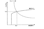
続いて、設定した要求パワーPe*に基づいてエンジン22の目標回転数Ne*と目標トルクTe*とからなる目標運転ポイントを設定する(ステップS120)。この設定は、エンジン22を効率よく動作させる動作ラインと要求パワーPe*とに基づいて行なわれる。エンジン22の動作ラインの一例と目標回転数Ne*と目標トルクTe*とを設定する様子を図6に示す。図示するように、目標回転数Ne*と目標トルクTe*は、動作ラインと要求パワーPe*(Ne*×Te*)が一定の曲線との交点により求めることができる。
Subsequently, based on the set required power Pe *, a target operating point consisting of the target rotational speed Ne * and the target torque Te * of the
こうしてエンジン22の目標運転ポイントを設定すると、設定した目標運転ポイントにおける目標回転数Ne*と入力したエンジン22の回転数Neとを比較し(ステップS130)、目標回転数Ne*が回転数Ne以下のときには目標回転数Ne*を実行用回転数Netagとして設定し(ステップS140)、設定した実行用回転数Netagとリングギヤ軸32aの回転数Nr(Nm2/Gr)と動力分配統合機構30のギヤ比ρとを用いて次式(1)によりモータMG1の目標回転数Nm1*を計算すると共に計算した目標回転数Nm1*と現在の回転数Nm1とに基づいて式(2)によりモータMG1のトルク指令Tm1*を計算する(ステップS170)。ここで、式(1)は、動力分配統合機構30の回転要素に対する力学的な関係式である。動力分配統合機構30の回転要素における回転数とトルクとの力学的な関係を示す共線図を図7に示す。図中、左のS軸はモータMG1の回転数Nm1であるサンギヤ31の回転数を示し、C軸はエンジン22の回転数Neであるキャリア34の回転数を示し、R軸はモータMG2の回転数Nm2を減速ギヤ35のギヤ比Grで除したリングギヤ32の回転数Nrを示す。式(1)は、この共線図を用いれば容易に導くことができる。なお、R軸上の2つの太線矢印は、モータMG1から出力されたトルクTm1がリングギヤ軸32aに作用するトルクと、モータMG2から出力されるトルクTm2が減速ギヤ35を介してリングギヤ軸32aに作用するトルクとを示す。また、式(2)は、モータMG1を目標回転数Nm1*で回転させるためのフィードバック制御における関係式であり、式(2)中、右辺第2項の「k1」は比例項のゲインであり、右辺第3項の「k2」は積分項のゲインである。
When the target operating point of the
Nm1*=Netag・(1+ρ)/ρ-Nm2/(Gr・ρ) (1)
Tm1*=ρ・Te*/(1+ρ)+k1(Nm1*-Nm1)+k2∫(Nm1*-Nm1)dt (2)
Nm1 * = Netag ・ (1 + ρ) / ρ-Nm2 / (Gr ・ ρ) (1)
Tm1 * = ρ ・ Te * / (1 + ρ) + k1 (Nm1 * -Nm1) + k2∫ (Nm1 * -Nm1) dt (2)
モータMG1の目標回転数Nm1*とトルク指令Tm1*とを計算すると、バッテリ50の入出力制限Win,Woutと計算したモータMG1のトルク指令Tm1*に現在のモータMG1の回転数Nm1を乗じて得られるモータMG1の消費電力(発電電力)との偏差をモータMG2の回転数Nm2で割ることによりモータMG2から出力してもよいトルクの上下限としてのトルク制限Tmin,Tmaxを次式(3)および式(4)により計算すると共に(ステップS180)、要求トルクTr*とトルク指令Tm1*と動力分配統合機構30のギヤ比ρを用いてモータMG2から出力すべきトルクとしての仮モータトルクTm2tmpを式(5)により計算し(ステップS190)、計算したトルク制限Tmin,Tmaxで仮モータトルクTm2tmpを制限した値としてモータMG2のトルク指令Tm2*を設定する(ステップS200)。このようにモータMG2のトルク指令Tm2*を設定することにより、駆動軸としてのリングギヤ軸32aに出力する要求トルクTr*を、バッテリ50の入出力制限Win,Woutの範囲内で制限したトルクとして設定することができる。なお、式(5)は、前述した図7の共線図から容易に導き出すことができる。
When the target rotational speed Nm1 * of the motor MG1 and the torque command Tm1 * are calculated, the input / output limits Win and Wout of the
Tmin=(Win-Tm1*・Nm1)/Nm2 (3)
Tmax=(Wout-Tm1*・Nm1)/Nm2 (4)
Tm2tmp=(Tr*+Tm1*/ρ)/Gr (5)
Tmin = (Win-Tm1 * ・ Nm1) / Nm2 (3)
Tmax = (Wout-Tm1 * ・ Nm1) / Nm2 (4)
Tm2tmp = (Tr * + Tm1 * / ρ) / Gr (5)
こうしてエンジン22の目標回転数Ne*や目標トルクTe*,モータMG1,MG2のトルク指令Tm1*,Tm2*を設定すると、エンジン22の目標回転数Ne*と目標トルクTe*についてはエンジンECU24に、モータMG1,MG2のトルク指令Tm1*,Tm2*についてはモータECU40にそれぞれ送信して(ステップS210)、駆動制御ルーチンを終了する。実行用回転数Netagと目標トルクTe*とを受信したエンジンECU24は、エンジン22が実行用回転数Netagと目標トルクTe*とによって示される運転ポイントで運転されるようにエンジン22における燃料噴射制御や点火制御などの制御を行なう。また、トルク指令Tm1*,Tm2*を受信したモータECU40は、トルク指令Tm1*でモータMG1が駆動されると共にトルク指令Tm2*でモータMG2が駆動されるようインバータ41,42のスイッチング素子のスイッチング制御を行なう。
Thus, when the target engine speed Ne *, the target torque Te *, and the torque commands Tm1 *, Tm2 * of the motors MG1, MG2 are set, the target engine speed Ne * and the target torque Te * of the
ステップS130で目標回転数Ne*がエンジン22の回転数Neより大きいと判定されたときには、電池温度Tbに基づいて上限上昇率ΔNを設定し(ステップS150)、エンジン22の回転数Neに上限上昇率ΔTを加えたものと目標回転数Ne*とのうち小さい方を実行用回転数Netagとして設定し(ステップS160)、設定した実行用回転数Netagを用いてモータMG1,MG2のトルク指令Tm1*,Tm2*を設定し(ステップS170〜S200)、エンジン22の目標回転数Ne*と目標トルクTe*についてはエンジンECU24に、モータMG1,MG2のトルク指令Tm1*,Tm2*についてはモータECU40にそれぞれ送信して(ステップS210)、駆動制御ルーチンを終了する。ここで、上限上昇率ΔNは、実施例では、電池温度Tbと上限上昇率ΔNとの関係を予め定めて上限上昇率設定用マップとしてROM74に記憶しておき、電池温度Tbが与えられるとマップから対応する上昇上限率ΔNを導出して設定するものとした。上限上昇率設定用マップの一例を図8に示す。実施例の上限上昇率設定用マップは、図示するように、電池温度Tbが閾値Tref1未満のときには振動や騒音が生じない程度の回転数変化量Nsetが上限上昇率ΔNに設定され、電池温度Tbが閾値Tref1以上で閾値Tref2未満のときには電池温度Tbが高いほど大きい値が上限上昇率ΔNに設定され、電池温度Tbが閾値Tref2以上のときにはエンジン22の回転により回転する部材(例えば、ピニオンギヤ33やサンギヤ31,キャリア34など)の耐久性により得られる許容上昇率Nmaxが上限上昇率ΔNに設定される。ここで、閾値Tref1は、図2に示すように、バッテリ50の入出力制限Win,Woutが電池温度Tbが高くなることによって大きく制限される温度より低い温度として設定されている。こうした制御により、エンジン22の回転数Neを迅速に上昇させることができ、エンジン22から出力するパワーを迅速に要求パワーPe*に近づけることができる。この結果、エンジン22から出力するパワーが要求パワーPe*に一致しないことによりバッテリ50から放電される電力を小さくすることができ、バッテリ50の充放電を抑制することができる。この結果、バッテリ50の温度上昇を抑制することができると共にバッテリ50の劣化を抑制することができる。
When it is determined in step S130 that the target rotational speed Ne * is greater than the rotational speed Ne of the
電池温度Tbが閾値Tref1以上のときに運転者によりアクセルペダル83が大きく踏み込まれて要求トルクTr*が急増して要求パワーPe*が急増したときのエンジン22の出力パワーとバッテリ50からの放電パワーの時間変化の様子の一例を図9に示す。図中、破線が電池温度Tbに基づいて振動や騒音が生じない程度の回転数変化量Nsetより大きい回転数変化量を上限上昇率ΔNとして用いた実施例におけるエンジンパワーとバッテリ放電パワーとの境界線を示し、一点鎖線が電池温度Tbが閾値Tref1でも振動や騒音が生じない程度の回転数変化量Nsetを上限上昇率ΔNとして用いた比較例におけるエンジンパワーとバッテリ放電パワーとの境界線を示す。図示するように、実施例におけるバッテリ放電パワーは、比較例に比して小さくなっている。したがって、バッテリ50の充放電を抑制し、バッテリ50の温度上昇を抑制することができる。
The output power of the
以上説明した実施例のハイブリッド自動車20によれば、電池温度Tbが閾値Tref1以上のときにエンジン22の回転数Neを増加するときには、電池温度Tbが閾値Tref1未満のときに上限上昇率ΔTに設定される回転数変化量Nsetより大きく電池温度Tbが高いほど大きい値を上限上昇率ΔNとして用いてエンジン22の回転数Neが目標回転数Ne*に向けて増加するよう実行用回転数Netagを設定し、この設定した実行用回転数Netagでエンジン22が運転されると共にバッテリ50の入出力制限Win,Woutの範囲内で要求トルクTr*が駆動軸としてのリングギヤ軸32aに出力されるようモータMG1,MG2のトルク指令Tm1*,Tm2*を設定してエンジン22とモータMG1,MG2を制御することにより、エンジン22の回転数Neを迅速に上昇させることができ、エンジン22から出力するパワーを迅速に要求パワーPe*に近づけることができる。これにより、エンジン22から出力するパワーが要求パワーPe*に一致しないことによりバッテリ50から放電される電力を小さくすることができ、バッテリ50の充放電を抑制することができる。この結果、バッテリ50の温度上昇を抑制することができると共にバッテリ50の劣化を抑制することができる。
According to the
実施例のハイブリッド自動車20では、電池温度Tbが閾値Tref1未満のときには振動や騒音が生じない程度の回転数変化量Nsetを上限上昇率ΔNとして設定し、電池温度Tbが閾値Tref1以上で閾値Tref2未満のときには電池温度Tbが高いほど大きい値を上限上昇率ΔNとして設定し、電池温度Tbが閾値Tref2以上のときにはエンジン22の回転により回転する部材の耐久性により得られる許容上昇率Nmaxを上限上昇率ΔNとして設定するものとしたが、図10の変形例の上限上昇率設定用マップに示すように、電池温度Tbが閾値Tref1未満のときには振動や騒音が生じない程度の回転数変化量Nsetを上限上昇率ΔNとして設定し、電池温度Tbが閾値Tref1以上のときにはエンジン22の回転により回転する部材の耐久性により得られる許容上昇率Nmaxを上限上昇率ΔNとして設定するものとしてもよい。また、電池温度Tbが閾値Tref1以上のときには電池温度Tbが閾値Tref1未満のときの回転数変化量Nsetより大きな回転数変化量であれば如何なる回転数変化量を上限上昇率ΔNとして設定するものとしても構わない。
In the
実施例のハイブリッド自動車20では、減速ギヤ35を介して駆動軸としてのリングギヤ軸32aにモータMG2を取り付けるものとしたが、リングギヤ軸32aにモータMG2を直接取り付けるものとしてもよいし、減速ギヤ35に代えて2段変速や3段変速,4段変速などの変速機を介してリングギヤ軸32aにモータMG2を取り付けるものとしても構わない。
In the
実施例のハイブリッド自動車20では、モータMG2の動力を減速ギヤ35により変速してリングギヤ軸32aに出力するものとしたが、駆動輪63a,63bとは異なる車軸に接続された車輪も路面を介して駆動輪63a,63bに接続されていると解すれば、駆動輪63a,63bとは異なる車軸に接続された車輪も駆動軸としてのリングギヤ軸32aに接続されていることになるから、図11の変形例のハイブリッド自動車120に例示するように、モータMG2の動力をリングギヤ軸32aが接続された車軸(駆動輪63a,63bが接続された車軸)とは異なる車軸(図11における車輪64a,64bに接続された車軸)に接続するものとしてもよい。
In the
実施例のハイブリッド自動車20では、エンジン22の動力を動力分配統合機構30を介して駆動輪63a,63bに接続された駆動軸としてのリングギヤ軸32aに出力するものとしたが、図12の変形例のハイブリッド自動車220に例示するように、エンジン22のクランクシャフト26に接続されたインナーロータ232と駆動輪63a,63bに動力を出力する駆動軸に接続されたアウターロータ234とを有し、エンジン22の動力の一部を駆動軸に伝達すると共に残余の動力を電力に変換する対ロータ電動機230を備えるものとしてもよい。
In the
また、こうしたハイブリッド自動車に適用するものに限定されるものではなく、自動車以外の車両や船舶,航空機などの移動体に搭載される動力出力装置の形態や建設設備などの移動しない設備に組み込まれた動力出力装置の形態としても構わない。さらに、こうした動力出力装置の制御方法の形態としてもよい。 In addition, it is not limited to those applied to such hybrid vehicles, but is incorporated into non-moving equipment such as forms of power output devices mounted on moving bodies such as vehicles other than automobiles, ships, and aircraft, and construction equipment. A power output device may be used. Furthermore, it is good also as a form of the control method of such a power output device.
ここで、実施例の主要な要素と課題を解決するための手段の欄に記載した発明の主要な要素との対応関係について説明する。実施例では、エンジン22が「内燃機関」に相当し、モータMG1が「発電機」に相当し、モータMG2が「電動機」に相当し、バッテリ50が「蓄電手段」に相当し、温度センサ51が「温度検出手段」に相当し、アクセル開度Accと車速Vとに基づいて要求トルクTr*を設定する図4の駆動制御ルーチンのステップS110の処理を実行するハイブリッド用電子制御ユニット70が「要求駆動力設定手段」に相当し、要求トルクTr*に基づいて要求パワーPe*を設定すると共に要求パワーPe*と動作ラインとに基づいて目標回転数Ne*と目標トルクTe*とからなる目標運転ポイントを設定する図4の駆動制御ルーチンのステップS110,S120の処理を実行するハイブリッド用電子制御ユニット70が「目標運転ポイント設定手段」に相当する。そして、電池温度Tbが閾値Tref1未満のときにエンジン22の回転数Neを増加するときには、振動や騒音が生じない程度の回転数変化量Nsetを上限上昇率ΔNとして用いてエンジン22の回転数Neが目標回転数Ne*に向けて増加するよう実行用回転数Netagを設定し、この設定した実行用回転数Netagでエンジン22が運転されると共に入出力制限Win,Woutの範囲内で要求トルクTr*が駆動軸としてのリングギヤ軸32aに出力されるようモータMG1,MG2のトルク指令Tm1*,Tm2*を設定し、実行用回転数Netagと目標トルクTe*とについてはエンジンECU24に、モータMG1,MG2のトルク指令Tm1*,Tm2*についてはモータECU40に送信し、電池温度Tbが閾値Tref1以上のときにエンジン22の回転数Neを増加するときには、回転数変化量Nsetより大きく電池温度Tbが高いほど大きい値を上限上昇率ΔNとして用いてエンジン22の回転数Neが目標回転数Ne*に向けて増加するよう実行用回転数Netagを設定し、この設定した実行用回転数Netagでエンジン22が運転されると共に入出力制限Win,Woutの範囲内で要求トルクTr*が駆動軸としてのリングギヤ軸32aに出力されるようモータMG1,MG2のトルク指令Tm1*,Tm2*を設定し、実行用回転数Netagと目標トルクTe*とについてはエンジンECU24に、モータMG1,MG2のトルク指令Tm1*,Tm2*についてはモータECU40に送信する、図4の駆動制御ルーチンのステップS130〜S210の処理を実行するハイブリッド用電子制御ユニット70と、実行用回転数Netagと目標トルクTe*とに基づいてエンジン22を制御するエンジンECU24と、トルク指令Tm1*,Tm2*に基づいてモータMG1,MG2を制御するモータECU40とが「制御手段」に相当する。また、対ロータ電動機230も「発電機」に相当し、動力分配統合機構30が「3軸式動力入出力手段」に相当する。
Here, the correspondence between the main elements of the embodiment and the main elements of the invention described in the column of means for solving the problems will be described. In the embodiment, the
ここで、「内燃機関」としては、ガソリンまたは軽油などの炭化水素系の燃料により動力を出力する内燃機関に限定されるものではなく、水素エンジンなど如何なるタイプの内燃機関であっても構わない。「発電機」としては、同期発電電動機として構成されたモータMG1に限定されるものではなく、誘導電動機など、動力を入出力可能なものであれば如何なるタイプの発電機としても構わない。「電動機」としては、同期発電電動機として構成されたモータMG2に限定されるものではなく、誘導電動機など、駆動軸に動力を入出力可能なものであれば如何なるタイプの電動機であっても構わない。「蓄電手段」としては、リチウムイオン二次電池として構成されたバッテリ50に限定されるものではなく、ニッケル水素二次電池や鉛蓄電池など種々の二次電池を用いることができ、発電機や電動機と電力のやりとりが可能で所定温度以上の高温領域で充放電してもよい最大電力の絶対値が小さくなる性能を有するものであれば如何なるものとしても構わない。「温度検出手段」としては、温度センサ51に限定されるものではなく蓄電手段の温度を検出するものであれば如何なるものとしても構わない。「要求駆動力設定手段」としては、アクセル開度Accと車速Vとに基づいて要求トルクTr*を設定するものに限定されるものではなく、アクセル開度Accだけに基づいて要求トルクを設定するものや走行経路が予め設定されているものにあっては走行経路における走行位置に基づいて要求トルクを設定するものなど、駆動軸に要求される要求駆動力を設定するものであれば如何なるものとしても構わない。「目標運転ポイント設定手段」としては、要求トルクTr*に基づいて要求パワーPe*を設定すると共に要求パワーPe*と動作ラインとに基づいて目標回転数Ne*と目標トルクTe*とからなる目標運転ポイントを設定するものに限定されるものではなく、要求駆動力と所定の制約とに基づいて内燃機関の目標回転数と目標トルクからなる目標運転ポイントを設定するものであれば如何なるものとしても構わない。「制御手段」としては、ハイブリッド用電子制御ユニット70とエンジンECU24とモータECU40とからなる組み合わせに限定されるものではなく単一の電子制御ユニットにより構成されるなどとしてもよい。また、「制御手段」としては、電池温度Tbが閾値Tref1未満のときにエンジン22の回転数Neを増加するときには、振動や騒音が生じない程度の回転数変化量Nsetを上限上昇率ΔNとして用いてエンジン22の回転数Neが目標回転数Ne*に向けて増加するよう実行用回転数Netagを設定し、この設定した実行用回転数Netagでエンジン22が運転されると共に入出力制限Win,Woutの範囲内で要求トルクTr*が駆動軸としてのリングギヤ軸32aに出力されるようモータMG1,MG2のトルク指令Tm1*,Tm2*を設定してエンジン22とモータMG1,MG2を制御し、電池温度Tbが閾値Tref1以上のときにエンジン22の回転数Neを増加するときには、回転数変化量Nsetより大きく電池温度Tbが高いほど大きい値を上限上昇率ΔNとして用いてエンジン22の回転数Neが目標回転数Ne*に向けて増加するよう実行用回転数Netagを設定し、この設定した実行用回転数Netagでエンジン22が運転されると共に入出力制限Win,Woutの範囲内で要求トルクTr*が駆動軸としてのリングギヤ軸32aに出力されるようモータMG1,MG2のトルク指令Tm1*,Tm2*を設定してエンジン22とモータMG1,MG2を制御するものに限定されるものではなく、電池温度Tbが閾値Tref1以上のときにエンジン22の回転数Neを増加するときには、電池温度Tbに拘わらずにエンジン22の回転により回転する部材の耐久性により得られる許容上昇率Nmaxを上限上昇率ΔNとして用いてエンジン22の回転数Neが目標回転数Ne*に向けて増加するよう実行用回転数Netagを設定し、この設定した実行用回転数Netagでエンジン22が運転されると共に入出力制限Win,Woutの範囲内で要求トルクTr*が駆動軸としてのリングギヤ軸32aに出力されるようモータMG1,MG2のトルク指令Tm1*,Tm2*を設定してエンジン22とモータMG1,MG2を制御するものとするなど、蓄電手段の温度が所定温度より低い閾値温度未満のときには内燃機関の回転数が第1の回転数上昇程度の範囲内で目標回転数に向けて変化しながら要求駆動力に基づく駆動力が駆動軸に出力されるよう内燃機関と発電機と電動機とを制御し、蓄電手段の温度が閾値温度以上のときには内燃機関の回転数が第1の回転数上昇程度より大きい第2の回転数上昇程度の範囲内で目標回転数に向けて変化しながら要求駆動力に基づく駆動力が駆動軸に出力されるよう内燃機関と発電機と電動機とを制御するものであれば如何なるものとしても構わない。「3軸式動力入出力手段」としては、上述の動力分配統合機構30に限定されるものではなく、ダブルピニオン式の遊星歯車機構を用いるものや複数の遊星歯車機構を組み合わせて4以上の軸に接続されるものやデファレンシャルギヤのように遊星歯車とは異なる作動作用を有するものなど、駆動軸と出力軸と発電機の回転軸との3軸に接続され3軸のうちのいずれか2軸に入出力される動力に基づいて残余の軸に動力を入出力するものであれば如何なるものとしても構わない。
Here, the “internal combustion engine” is not limited to an internal combustion engine that outputs power using a hydrocarbon fuel such as gasoline or light oil, and may be any type of internal combustion engine such as a hydrogen engine. The “generator” is not limited to the motor MG1 configured as a synchronous generator motor, and may be any type of generator such as an induction motor that can input and output power. The “motor” is not limited to the motor MG2 configured as a synchronous generator motor, and may be any type of motor as long as it can input and output power to the drive shaft, such as an induction motor. . The “storage means” is not limited to the
なお、実施例の主要な要素と課題を解決するための手段の欄に記載した発明の主要な要素との対応関係は、実施例が課題を解決するための手段の欄に記載した発明を実施するための最良の形態を具体的に説明するための一例であることから、課題を解決するための手段の欄に記載した発明の要素を限定するものではない。即ち、課題を解決するための手段の欄に記載した発明についての解釈はその欄の記載に基づいて行なわれるべきものであり、実施例は課題を解決するための手段の欄に記載した発明の具体的な一例に過ぎないものである。 The correspondence between the main elements of the embodiment and the main elements of the invention described in the column of means for solving the problem is the same as that of the embodiment described in the column of means for solving the problem. It is an example for specifically explaining the best mode for doing so, and does not limit the elements of the invention described in the column of means for solving the problem. That is, the interpretation of the invention described in the column of means for solving the problems should be made based on the description of the column, and the examples are those of the invention described in the column of means for solving the problems. It is only a specific example.
以上、本発明の実施の形態について実施例を用いて説明したが、本発明はこうした実施例に何等限定されるものではなく、本発明の要旨を逸脱しない範囲内において、種々なる形態で実施し得ることは勿論である。 The embodiments of the present invention have been described using the embodiments. However, the present invention is not limited to these embodiments, and can be implemented in various forms without departing from the gist of the present invention. Of course you get.
本発明は、動力出力装置やこれを搭載する車両の製造産業などに利用可能である。 The present invention is applicable to a power output device and a manufacturing industry of a vehicle equipped with the power output device.
20,120,220 ハイブリッド自動車、22 エンジン、24 エンジン用電子制御ユニット(エンジンECU)、26 クランクシャフト、28 ダンパ、30 動力分配統合機構、31 サンギヤ、32 リングギヤ、32a リングギヤ軸、33 ピニオンギヤ、34 キャリア、35 減速ギヤ、40 モータ用電子制御ユニット(モータECU)、41,42 インバータ、43,44 回転位置検出センサ、50 バッテリ、51 温度センサ、52 バッテリ用電子制御ユニット(バッテリECU)、54 電力ライン、60 ギヤ機構、62 デファレンシャルギヤ、63a,63b 駆動輪、64a,64b 車輪、70 ハイブリッド用電子制御ユニット、72 CPU、74 ROM、76 RAM、80 イグニッションスイッチ、81 シフトレバー、82 シフトポジションセンサ、83 アクセルペダル、84 アクセルペダルポジションセンサ、85 ブレーキペダル、86 ブレーキペダルポジションセンサ、88 車速センサ、230 対ロータ電動機、232 インナーロータ、234 アウターロータ、MG1,MG2 モータ。
20, 120, 220 Hybrid vehicle, 22 engine, 24 engine electronic control unit (engine ECU), 26 crankshaft, 28 damper, 30 power distribution integration mechanism, 31 sun gear, 32 ring gear, 32a ring gear shaft, 33 pinion gear, 34
Claims (7)
前記駆動軸に動力を出力する内燃機関と、
動力の入出力が可能で前記内燃機関からの動力の一部を用いて発電する発電機と、
前記駆動軸に動力を出力する電動機と、
前記発電機および前記電動機と電力のやりとりが可能で所定温度以上の高温領域で充放電してもよい最大電力の絶対値が小さくなる性能を有する蓄電手段と、
前記蓄電手段の温度を検出する温度検出手段と、
前記駆動軸に要求される要求駆動力を設定する要求駆動力設定手段と、
前記設定された要求駆動力と所定の制約とに基づいて前記内燃機関の目標回転数と目標トルクからなる目標運転ポイントを設定する目標運転ポイント設定手段と、
前記検出された前記蓄電手段の温度が前記所定温度より低い閾値温度未満のときには前記内燃機関の回転数が第1の回転数上昇程度の範囲内で前記設定された目標回転数に向けて変化しながら前記設定された要求駆動力に基づく駆動力が前記駆動軸に出力されるよう前記内燃機関と前記発電機と前記電動機とを制御し、前記検出された前記蓄電手段の温度が前記閾値温度以上のときには前記内燃機関の回転数が前記第1の回転数上昇程度より大きい第2の回転数上昇程度の範囲内で前記設定された目標回転数に向けて変化しながら前記設定された要求駆動力に基づく駆動力が前記駆動軸に出力されるよう前記内燃機関と前記発電機と前記電動機とを制御する制御手段と、
を備える動力出力装置。 A power output device that outputs power to a drive shaft,
An internal combustion engine that outputs power to the drive shaft;
A generator capable of inputting and outputting power and generating electric power using a part of the power from the internal combustion engine;
An electric motor that outputs power to the drive shaft;
Electric power storage means capable of exchanging electric power with the generator and the electric motor and having the performance of reducing the absolute value of the maximum electric power that may be charged and discharged in a high temperature region above a predetermined temperature;
Temperature detecting means for detecting the temperature of the power storage means;
Required driving force setting means for setting required driving force required for the drive shaft;
Target operating point setting means for setting a target operating point comprising a target rotational speed and a target torque of the internal combustion engine based on the set required driving force and a predetermined constraint;
When the detected temperature of the power storage means is lower than a threshold temperature lower than the predetermined temperature, the rotational speed of the internal combustion engine changes toward the set target rotational speed within a range of the first rotational speed increase. However, the internal combustion engine, the generator, and the electric motor are controlled such that a driving force based on the set required driving force is output to the driving shaft, and the detected temperature of the power storage means is equal to or higher than the threshold temperature. In this case, the set required driving force while the engine speed changes toward the set target engine speed within a range of the second engine speed increase that is greater than the first engine speed increase. Control means for controlling the internal combustion engine, the generator, and the electric motor so that a driving force based on the output is output to the drive shaft;
A power output device comprising:
前記駆動軸に要求された要求駆動力と所定の制約とに基づいて前記内燃機関の目標回転数と目標トルクからなる目標運転ポイントを設定し、
前記蓄電手段の温度が前記所定温度より低い閾値温度未満のときには前記内燃機関の回転数が第1の回転数上昇程度の範囲内で前記設定した目標回転数に向けて変化しながら前記要求駆動力に基づく駆動力が前記駆動軸に出力されるよう前記内燃機関と前記発電機と前記電動機とを制御し、前記蓄電手段の温度が前記閾値温度以上のときには前記内燃機関の回転数が前記第1の回転数上昇程度より大きい第2の回転数上昇程度の範囲内で前記設定した目標回転数に向けて変化しながら前記要求駆動力に基づく駆動力が前記駆動軸に出力されるよう前記内燃機関と前記発電機と前記電動機とを制御する、
ことを特徴とする動力出力装置の制御方法。 An internal combustion engine that outputs power to the drive shaft; a generator that can input and output power; and that generates power using a portion of the power from the internal combustion engine; an electric motor that outputs power to the drive shaft; and the generator And a power storage means capable of exchanging electric power with the electric motor and capable of charging / discharging in a high temperature region equal to or higher than a predetermined temperature and having a performance that reduces the absolute value of the maximum power,
Based on the required driving force required for the drive shaft and predetermined constraints, a target operating point consisting of the target rotational speed and target torque of the internal combustion engine is set,
When the temperature of the power storage means is lower than a threshold temperature lower than the predetermined temperature, the required driving force while the rotational speed of the internal combustion engine changes toward the set target rotational speed within a range where the first rotational speed increases. The internal combustion engine, the generator, and the electric motor are controlled so that a driving force based on the power is output to the drive shaft, and when the temperature of the power storage means is equal to or higher than the threshold temperature, the rotational speed of the internal combustion engine is the first The internal combustion engine is configured such that a driving force based on the required driving force is output to the drive shaft while changing toward the set target rotation speed within a range of a second rotation speed increase that is greater than a rotation speed increase of And controlling the generator and the electric motor,
A control method for a power output apparatus.
Priority Applications (1)
| Application Number | Priority Date | Filing Date | Title |
|---|---|---|---|
| JP2008185213A JP2010023588A (en) | 2008-07-16 | 2008-07-16 | Power output device, vehicle mounted thereon, and control method of motive power output device |
Applications Claiming Priority (1)
| Application Number | Priority Date | Filing Date | Title |
|---|---|---|---|
| JP2008185213A JP2010023588A (en) | 2008-07-16 | 2008-07-16 | Power output device, vehicle mounted thereon, and control method of motive power output device |
Publications (1)
| Publication Number | Publication Date |
|---|---|
| JP2010023588A true JP2010023588A (en) | 2010-02-04 |
Family
ID=41729816
Family Applications (1)
| Application Number | Title | Priority Date | Filing Date |
|---|---|---|---|
| JP2008185213A Pending JP2010023588A (en) | 2008-07-16 | 2008-07-16 | Power output device, vehicle mounted thereon, and control method of motive power output device |
Country Status (1)
| Country | Link |
|---|---|
| JP (1) | JP2010023588A (en) |
Cited By (3)
| Publication number | Priority date | Publication date | Assignee | Title |
|---|---|---|---|---|
| JP2011239629A (en) * | 2010-05-13 | 2011-11-24 | Mitsubishi Motors Corp | Control device for electric vehicle |
| WO2013102945A1 (en) * | 2012-01-04 | 2013-07-11 | トヨタ自動車株式会社 | Vehicle control device |
| JP2020104646A (en) * | 2018-12-27 | 2020-07-09 | トヨタ自動車株式会社 | Power generation control device |
-
2008
- 2008-07-16 JP JP2008185213A patent/JP2010023588A/en active Pending
Cited By (3)
| Publication number | Priority date | Publication date | Assignee | Title |
|---|---|---|---|---|
| JP2011239629A (en) * | 2010-05-13 | 2011-11-24 | Mitsubishi Motors Corp | Control device for electric vehicle |
| WO2013102945A1 (en) * | 2012-01-04 | 2013-07-11 | トヨタ自動車株式会社 | Vehicle control device |
| JP2020104646A (en) * | 2018-12-27 | 2020-07-09 | トヨタ自動車株式会社 | Power generation control device |
Similar Documents
| Publication | Publication Date | Title |
|---|---|---|
| JP4888154B2 (en) | Vehicle and control method thereof | |
| JP4135681B2 (en) | POWER OUTPUT DEVICE, HYBRID VEHICLE HAVING THE SAME AND CONTROL METHOD THEREOF | |
| JP2008265652A (en) | Hybrid vehicle and control method thereof | |
| JP4215043B2 (en) | POWER OUTPUT DEVICE, VEHICLE MOUNTING THE SAME, AND METHOD FOR CONTROLLING POWER OUTPUT DEVICE | |
| JP2010202132A (en) | Hybrid car and method for controlling the same | |
| JP5682639B2 (en) | Hybrid car | |
| JP2010195255A (en) | Hybrid vehicle and control method thereof | |
| JP2010132141A (en) | Power output device, vehicle, drive device and control method for the power output device | |
| JP2011219008A (en) | Vehicle and method of controlling the same | |
| JP2010023588A (en) | Power output device, vehicle mounted thereon, and control method of motive power output device | |
| JP2009149154A (en) | Vehicle and control method thereof | |
| JP2009161132A (en) | VEHICLE, DRIVE DEVICE, AND CONTROL METHOD THEREOF | |
| JP4957267B2 (en) | Power output apparatus, automobile equipped with the same, and control method of power output apparatus | |
| JP4365354B2 (en) | Power output apparatus, automobile equipped with the same, and control method of power output apparatus | |
| JP4196986B2 (en) | Hybrid vehicle and control method thereof | |
| JP2009137369A (en) | Vehicle, drive device, and vehicle control method | |
| JP2009184387A (en) | Hybrid vehicle and control method thereof | |
| JP4977055B2 (en) | POWER OUTPUT DEVICE, ITS CONTROL METHOD, AND VEHICLE | |
| JP2010221896A (en) | Hybrid vehicle and control method thereof | |
| JP2009023527A (en) | Vehicle and control method thereof | |
| JP4301252B2 (en) | POWER OUTPUT DEVICE, ITS CONTROL METHOD, AND VEHICLE | |
| JP4345738B2 (en) | Vehicle and control method thereof | |
| JP4983626B2 (en) | Hybrid vehicle and control method thereof | |
| JP2008239074A (en) | POWER OUTPUT DEVICE, AUTOMOBILE MOUNTING THE SAME, CONTROL METHOD FOR POWER OUTPUT DEVICE, DRIVE DEVICE, CONTROL METHOD FOR DRIVE DEVICE | |
| JP4258519B2 (en) | Vehicle and control method thereof |