JP2009536064A - Apparatus and method for controlled release of a quantity of a substance - Google Patents
Apparatus and method for controlled release of a quantity of a substance Download PDFInfo
- Publication number
- JP2009536064A JP2009536064A JP2009508566A JP2009508566A JP2009536064A JP 2009536064 A JP2009536064 A JP 2009536064A JP 2009508566 A JP2009508566 A JP 2009508566A JP 2009508566 A JP2009508566 A JP 2009508566A JP 2009536064 A JP2009536064 A JP 2009536064A
- Authority
- JP
- Japan
- Prior art keywords
- compartment
- compartments
- substrate
- actuation
- contact
- Prior art date
- Legal status (The legal status is an assumption and is not a legal conclusion. Google has not performed a legal analysis and makes no representation as to the accuracy of the status listed.)
- Pending
Links
Images


Classifications
-
- A—HUMAN NECESSITIES
- A61—MEDICAL OR VETERINARY SCIENCE; HYGIENE
- A61K—PREPARATIONS FOR MEDICAL, DENTAL OR TOILETRY PURPOSES
- A61K9/00—Medicinal preparations characterised by special physical form
- A61K9/0087—Galenical forms not covered by A61K9/02 - A61K9/7023
- A61K9/0097—Medicinal compositions released by microdevices, e.g. microelectromechanical systems [MEMS], microdevices comprising chips or microdevices on silicon
-
- A—HUMAN NECESSITIES
- A61—MEDICAL OR VETERINARY SCIENCE; HYGIENE
- A61M—DEVICES FOR INTRODUCING MEDIA INTO, OR ONTO, THE BODY; DEVICES FOR TRANSDUCING BODY MEDIA OR FOR TAKING MEDIA FROM THE BODY; DEVICES FOR PRODUCING OR ENDING SLEEP OR STUPOR
- A61M2205/00—General characteristics of the apparatus
- A61M2205/02—General characteristics of the apparatus characterised by a particular materials
- A61M2205/0244—Micromachined materials, e.g. made from silicon wafers, microelectromechanical systems [MEMS] or comprising nanotechnology
-
- A—HUMAN NECESSITIES
- A61—MEDICAL OR VETERINARY SCIENCE; HYGIENE
- A61M—DEVICES FOR INTRODUCING MEDIA INTO, OR ONTO, THE BODY; DEVICES FOR TRANSDUCING BODY MEDIA OR FOR TAKING MEDIA FROM THE BODY; DEVICES FOR PRODUCING OR ENDING SLEEP OR STUPOR
- A61M5/00—Devices for bringing media into the body in a subcutaneous, intra-vascular or intramuscular way; Accessories therefor, e.g. filling or cleaning devices, arm-rests
- A61M5/14—Infusion devices, e.g. infusing by gravity; Blood infusion; Accessories therefor
- A61M5/142—Pressure infusion, e.g. using pumps
- A61M5/14244—Pressure infusion, e.g. using pumps adapted to be carried by the patient, e.g. portable on the body
- A61M5/14276—Pressure infusion, e.g. using pumps adapted to be carried by the patient, e.g. portable on the body specially adapted for implantation
-
- A—HUMAN NECESSITIES
- A61—MEDICAL OR VETERINARY SCIENCE; HYGIENE
- A61M—DEVICES FOR INTRODUCING MEDIA INTO, OR ONTO, THE BODY; DEVICES FOR TRANSDUCING BODY MEDIA OR FOR TAKING MEDIA FROM THE BODY; DEVICES FOR PRODUCING OR ENDING SLEEP OR STUPOR
- A61M5/00—Devices for bringing media into the body in a subcutaneous, intra-vascular or intramuscular way; Accessories therefor, e.g. filling or cleaning devices, arm-rests
- A61M5/14—Infusion devices, e.g. infusing by gravity; Blood infusion; Accessories therefor
- A61M5/168—Means for controlling media flow to the body or for metering media to the body, e.g. drip meters, counters ; Monitoring media flow to the body
- A61M5/172—Means for controlling media flow to the body or for metering media to the body, e.g. drip meters, counters ; Monitoring media flow to the body electrical or electronic
Landscapes
- Health & Medical Sciences (AREA)
- Dermatology (AREA)
- Chemical & Material Sciences (AREA)
- Medicinal Chemistry (AREA)
- Pharmacology & Pharmacy (AREA)
- Epidemiology (AREA)
- Life Sciences & Earth Sciences (AREA)
- Animal Behavior & Ethology (AREA)
- General Health & Medical Sciences (AREA)
- Public Health (AREA)
- Veterinary Medicine (AREA)
- Electrotherapy Devices (AREA)
- Infusion, Injection, And Reservoir Apparatuses (AREA)
Abstract
本発明は、所定量の物質の制御放出のための装置および画室(20)から所定量の物質を制御可能的に放出する方法を提供する。本装置は、第一の数の画室を基板(11)中に有し、各画室は少なくとも一つの放出機構(30)によって閉じられる。本装置はさらに、第二の数の作動接点(40)を有しており、該第二の数の作動接点は、前記第二の数の作動接点のうちの少なくとも第一の作動接点と第二の作動接点との間に作動信号を加えることによって前記第一の数の画室のうちの一つの画室から前記物質を放出するためであり、前記第一の数は前記第二の数より大きく、前記作動接点のそれぞれは前記基板中または前記基板上に、少なくとも一つの画室に電気的に接続する少なくとも一つの導体経路を有しており、前記作動接点は前記基板中または前記基板上でメッシュ様構造を形成する。
The present invention provides an apparatus for controlled release of a predetermined amount of material and a method for controllably releasing a predetermined amount of material from a compartment (20). The apparatus has a first number of compartments in the substrate (11), each compartment being closed by at least one discharge mechanism (30). The apparatus further includes a second number of working contacts (40), wherein the second number of working contacts is at least one of the second number of working contacts and a first number of working contacts. For releasing the substance from one of the first number of compartments by applying an actuation signal between the two actuation contacts, wherein the first number is greater than the second number. Each of the working contacts has at least one conductor path electrically connected to at least one compartment in or on the substrate, the working contacts meshed in or on the substrate. Form a like structure.
Description
本発明は、所定量の物質の制御放出のための装置に関する。本発明はさらに、画室から所定量の物質を制御可能的に放出する方法に関する。 The present invention relates to an apparatus for the controlled release of a predetermined amount of substance. The invention further relates to a method for controllably releasing a predetermined amount of a substance from a compartment.
少量かつ精密な量の一または複数の化学物質の担体流体中への精確な送達は、科学および産業の多くの異なる分野において大いに重要である。医学における例としては、静脈注射法、肺もしくは吸入法による、あるいは血管ステント・デバイスからの薬物の放出による、患者への薬物の送達が含まれる。診断における例としては、DNAもしくは遺伝子解析を実施するための流体中での反応の放出、組み合わせ化学、あるいは環境試料中の特定の分子の検出が含まれる。担体流体中への化学物質の送達に関わる他の応用としては、デバイスから空気中への香水および治療用芳香の放出ならびに飲料製品を生産するために液体中への風味剤の放出が含まれる。 Accurate delivery of small and precise amounts of one or more chemicals into a carrier fluid is of great importance in many different fields of science and industry. Examples in medicine include delivery of a drug to a patient by intravenous injection, pulmonary or inhalation, or by release of the drug from a vascular stent device. Examples in diagnosis include release of reactions in fluids to perform DNA or genetic analysis, combinatorial chemistry, or detection of specific molecules in environmental samples. Other applications involving the delivery of chemicals into the carrier fluid include the release of perfume and therapeutic fragrances from the device into the air and the release of flavors into the liquid to produce a beverage product.
所定量の物質の制御放出のための装置は一般に知られている。たとえば、米国特許出願US2004/0034332A1は薬物の制御された送達のためのインプラント可能なデバイスを開示している。該デバイスは、放出されるべき分子を含む貯留部を有するマイクロチップを含む。マイクロチップ・デバイスは、基板と、放出されるべき分子を含む基板中の少なくとも二つの貯留部と、貯留部の一部分の上または内部でかつ前記分子にかぶさって位置される貯留部キャップとを含み、前記分子が当該デバイスから、前記貯留部キャップを通じた拡散によって、あるいは前記貯留部キャップの分解または破裂に際して、制御可能的に放出されるようになっている。単一のマイクロチップの前記貯留部のそれぞれは、独立して放出されることのできる異なる分子を含んでいてもよい。既知のデバイスの一つの欠点は、各貯留部が、電流を加えることによって封印層または前記キャップを電気的に破って薬物を放出するために使われる電極と直接接触しているということである。従来技術のシステムの弱点は、薬物が放出されるべき各画室について、あるいは各貯留部について一つの外部電気接続が必要とされるということである。すべての電気的接続のために必要とされるスペースは禁止的になるため、これは単一のデバイス上で実現できる画室の数を強く制限する。 Devices for the controlled release of a predetermined amount of substance are generally known. For example, US Patent Application US2004 / 0034332A1 discloses an implantable device for controlled delivery of drugs. The device includes a microchip having a reservoir containing molecules to be released. The microchip device includes a substrate, at least two reservoirs in the substrate containing molecules to be released, and a reservoir cap positioned over or within a portion of the reservoir and overlying the molecules. The molecule is controllably released from the device by diffusion through the reservoir cap or upon degradation or rupture of the reservoir cap. Each of the reservoirs of a single microchip may contain different molecules that can be released independently. One drawback of the known device is that each reservoir is in direct contact with an electrode that is used to electrically break the sealing layer or the cap to release the drug by applying an electric current. The weakness of the prior art system is that one external electrical connection is required for each compartment from which the drug is to be released, or for each reservoir. This severely limits the number of compartments that can be implemented on a single device, as the space required for all electrical connections becomes prohibitive.
したがって、所定量の物質の制御放出のための装置であって、独立して制御されるべき各画室について一つまたは複数の外部電気接続を設ける必要なしに増加した数の貯留部または画室をもつ装置を提供することが本発明の目的である。 Thus, a device for the controlled release of a predetermined amount of substance, with an increased number of reservoirs or compartments without having to provide one or more external electrical connections for each compartment to be controlled independently It is an object of the present invention to provide an apparatus.
上記の目的は、本発明に基づく所定量の物質の制御放出のための装置および方法によって達成される。当該装置は、本発明の第一の実施形態によれば、第一の数の画室を基板中に有し、各画室は少なくとも一つの放出機構によって閉じられ、当該装置はさらに、第二の数の作動接点を有しており、該第二の数の作動接点は、前記第二の数の作動接点(actuation contact)のうちの少なくとも第一の作動接点と第二の作動接点との間に作動信号(actuation signal)を加えることによって前記第一の数の画室のうちの一つの画室から前記物質を放出するためであり、前記第一の数は前記第二の数より大きく、前記作動接点のそれぞれは前記基板中または前記基板上に、少なくとも一つの画室に電気的に接続する少なくとも一つの導体経路を有しており、前記作動接点は前記基板中または前記基板上でメッシュ様構造を形成する。 The above objective is accomplished by an apparatus and method for controlled release of a predetermined amount of substance according to the present invention. According to a first embodiment of the present invention, the apparatus has a first number of compartments in the substrate, each compartment is closed by at least one discharge mechanism, the apparatus further comprising a second number The second number of working contacts is between at least a first working contact and a second working contact of the second number of actuating contacts. For releasing the substance from one of the first number of compartments by applying an activation signal, wherein the first number is greater than the second number and the actuation contact Each having at least one conductor path electrically connected to at least one compartment in or on the substrate, the actuating contacts forming a mesh-like structure in or on the substrate To do.
上記の目的は、本発明に基づく所定量の物質の制御放出のための装置および方法によって達成される。当該装置は、本発明の第二の実施形態によれば、第一の数の画室を基板中に有し、各画室は少なくとも一つの放出機構によって閉じられ、当該装置はさらに、第二の数の作動接点を有しており、該第二の数の作動接点は、前記第二の数の作動接点のうちの少なくとも第一の作動接点と第二の作動接点との間に作動信号を加えることによって前記第一の数の画室のうちの一つの画室から前記物質を放出するためであり、前記第一の数は前記第二の数より大きく、前記作動接点のそれぞれは前記基板中または前記基板上に、少なくとも一つの画室に電気的に接続する少なくとも一つの導体経路を有しており、前記一つの画室は、前記第一の作動接点と前記第二の作動接点との間の作動信号に依存して作動させられる。 The above objective is accomplished by an apparatus and method for controlled release of a predetermined amount of substance according to the present invention. According to a second embodiment of the present invention, the device has a first number of compartments in the substrate, each compartment is closed by at least one discharge mechanism, the device further comprising a second number And the second number of working contacts applies an actuating signal between at least a first working contact and a second working contact of the second number of working contacts. To release the substance from one of the first number of compartments, wherein the first number is greater than the second number and each of the working contacts is in the substrate or the On the substrate, has at least one conductor path electrically connected to at least one compartment, the one compartment having an actuation signal between the first actuation contact and the second actuation contact. Operated depending on.
本発明の両実施形態に基づく装置の利点は、複数の個々の薬物放出画室に基づく制御された物質または薬物送達のためのシステムであって、作動接点の数に比べて画室の数が非常に多く、制御要件ならびに製造要件および結果として装置のコストが軽減されるものを実現することが可能であるということである。従来技術によれば、各画室を接続線によって個々に接続する必要によって画室の数は強く制限されるか、その代わりに制御論理の面でのコストおよび製造コストが比較的高くなる。以下に言及される作動接点のメッシュ状の構成または構造は、少なくとも潜在的に一つの放出機構が各作動接点間に設けられる構成についてのものである。 An advantage of the device according to both embodiments of the present invention is a system for controlled substance or drug delivery based on a plurality of individual drug release compartments, wherein the number of compartments is very large compared to the number of actuation contacts. Often, it is possible to realize control requirements as well as manufacturing requirements and consequently reduced equipment costs. According to the prior art, the number of compartments is strongly limited by the need to connect each compartment individually by connecting lines, or instead the control logic and manufacturing costs are relatively high. The mesh-like configuration or structure of the working contacts mentioned below is for a configuration in which at least one potential release mechanism is provided between each working contact.
本発明の両実施形態のさらなる利点は、たとえば外部薬物送達システム(パッチ)やインプラント可能な薬物送達システムまたは経口薬物送達システム(eピル)といった応用が可能にされるということである。本発明に基づく薬物送達システムは、単一の薬物の送達のために適用されてもよいが、有利なことに、いくつかの異なる薬物が諸画室の同じ配置からまたは同じデバイスから施与されるシステムに適用できる。 A further advantage of both embodiments of the present invention is that it allows applications such as external drug delivery systems (patches), implantable drug delivery systems or oral drug delivery systems (e-pills). The drug delivery system according to the invention may be applied for the delivery of a single drug, but advantageously several different drugs are applied from the same arrangement of compartments or from the same device Applicable to the system.
さらに、本発明のすべての実施形態によれば、作動させられるべく意図された放出機構が実際に作動させられる、すなわち物質放出のために開かれるかどうかを検証することが可能である。放出機構としての膜または閉鎖キャップの場合、この開放または放出は、膜または閉鎖キャップの「吹き飛ばし(blowing)」とも呼ばれる。 Furthermore, according to all embodiments of the invention, it is possible to verify whether the release mechanism intended to be actuated is actually actuated, ie opened for substance release. In the case of a membrane or closure cap as a release mechanism, this opening or release is also referred to as “blowing” of the membrane or closure cap.
本発明の前記第一の実施形態によれば、好ましくは、前記第一の数は前記第二の数の二乗の4分の1よりも大きく、好ましくは前記第一の数はほぼ前記第二の数の二乗の2分の1から前記第二の数の2分の1を引いたものによって与えられる。結果として、比較的小さな第二の数の作動接点を必要とするだけで、大きな第一の数の画室がアドレス指定できる。それにより、特に、所与の第二の数の作動接点について、放出機構の配線または接続パターンのマトリクス構成の場合よりも大きな第一の数の画室を提供することが可能である。 According to the first embodiment of the present invention, preferably the first number is greater than a quarter of the square of the second number, preferably the first number is approximately the second number. Is given by one half the square of the number minus one half of the second number. As a result, a large first number of compartments can be addressed by requiring only a relatively small second number of working contacts. Thereby, it is possible in particular to provide a larger first number of compartments for a given second number of working contacts than in the case of a matrix arrangement of discharge mechanism wiring or connection patterns.
さらに、本発明の前記第一の実施形態によれば、好ましくは、前記第一の数は前記第二の数の二乗よりも小さく、前記作動接点は交差なしに設けられ、好ましくは前記第一の数はほぼ前記第二の数の3倍から6を引いたものによって与えられる。さらに、前記第一の数が前記第二の数の二乗より小さく、前記作動接点が交差なしに前記諸画室の一方の側に設けられることが好ましく、好ましくは前記第一の数はほぼ前記第二の数の2倍から3を引いたものによって与えられる。これらの好ましい実施形態では、有利なことに、作動接点の交差を設けるための追加的な層が省けるという点で、本発明の装置を生産するための製造コストを軽減することが可能である。さらに、作動接点を放出機構の構成の一方の側にのみ設けることが可能である。 Furthermore, according to the first embodiment of the present invention, preferably, the first number is less than the square of the second number, and the operating contact is provided without crossing, preferably the first number. The number of is approximately given by 3 times the second number minus 6. Further, it is preferable that the first number is smaller than the square of the second number, and the operating contact is provided on one side of the compartments without crossing, preferably the first number is approximately the first number. It is given by 2 times the number of 2 minus 3. In these preferred embodiments, it is possible to reduce the manufacturing costs for producing the device of the present invention, advantageously in that an additional layer for providing a working contact intersection can be omitted. Furthermore, it is possible to provide the actuating contact only on one side of the release mechanism configuration.
本発明の両実施形態によれば、前記第一および/または第二の作動接点が、前記一つの画室を選択的に作動させるための選択素子を有することが好ましい。好ましくは、前記選択素子は抵抗素子である。ここで、前記作動信号として異なる電圧を加えることによって異なる画室が選択される。よって、作動接点の前記第二の数に比して前記第一の数を高めることが可能である。 According to both embodiments of the present invention, it is preferable that the first and / or second actuation contact has a selection element for selectively actuating the one compartment. Preferably, the selection element is a resistance element. Here, different compartments are selected by applying different voltages as the actuation signal. Thus, it is possible to increase the first number compared to the second number of operating contacts.
本発明の両実施形態によれば、前記抵抗素子が非線形素子、好ましくはダイオードであることが好ましい。よって、所与の安全性マージンおよび所与の電圧差について一層多くの数の画室を選択することが可能である。 According to both embodiments of the present invention, the resistive element is preferably a non-linear element, preferably a diode. Thus, a greater number of compartments can be selected for a given safety margin and a given voltage difference.
本発明の前記第二の実施形態によれば、前記選択素子が容量素子または誘導素子であることが好ましい。ここで、前記作動信号として異なる周波数を加えることによって異なる画室が選択される。よって、周波数の選択による放出機構の選択が非常に有利なことに可能である。 According to the second embodiment of the present invention, the selection element is preferably a capacitive element or an inductive element. Here, different compartments are selected by applying different frequencies as the actuation signal. Thus, the selection of the release mechanism by the choice of frequency can be very advantageous.
本発明の前記第二の実施形態によれば、前記作動接点が基板中または基板上でメッシュ様構造を形成することが好ましい。よって、本発明の第二の実施形態についても、本発明の前記第一の実施形態の諸利点を達成することが可能である。 According to the second embodiment of the present invention, it is preferable that the operating contact forms a mesh-like structure in or on the substrate. Therefore, the advantages of the first embodiment of the present invention can also be achieved for the second embodiment of the present invention.
本発明の両実施形態によれば、前記放出機構は一度きりの放出機構である。これは、閾値を超える放出信号を加えることによって何らかの仕方で放出機構が「破壊」され、放出機構が再使用できないということを意味している。よって、放出機構を非常にコスト効率がよく簡単な仕方で製造することが可能である。にもかかわらず、本発明は、いったん(最初に)開かれてから閉じることが可能で、少なくとも二度目に再び開くことが可能な放出機構をも言及する。再閉鎖可能かつ再開放可能なそのような実施形態は、通例より高いコストを含意するので、それほど好ましくない。 According to both embodiments of the present invention, the release mechanism is a one-time release mechanism. This means that by adding a release signal that exceeds a threshold, the release mechanism is “broken” in some way and the release mechanism cannot be reused. Thus, it is possible to manufacture the release mechanism in a very cost-effective and simple manner. Nevertheless, the present invention also refers to a release mechanism that can be opened (initially) and then closed and reopened at least a second time. Such an embodiment that can be reclosed and reopened is less preferred as it usually implies higher costs.
本発明の両実施形態のある好ましい変形によれば、本発明に基づく放出機構は閉鎖キャップによって提供される。閉鎖キャップは閉鎖機構の好ましい個別的な実施形態である。他の放出機構の例としては:加熱されると薬物を放出するポリマー膜またはゲル(専用の化学結合を断つなど、担体マトリクスの分解またはその属性の変更)または電位を加えるとある種の分子に対する透過性を変える膜がある。 According to one preferred variant of both embodiments of the invention, the release mechanism according to the invention is provided by a closure cap. A closure cap is a preferred individual embodiment of the closure mechanism. Examples of other release mechanisms are: polymer membranes or gels that release drugs when heated (degradation of the carrier matrix or changes in its properties, such as breaking dedicated chemical bonds) or for certain molecules when an electrical potential is applied There are membranes that change permeability.
本発明の両実施形態のさらなる好ましい変形では、第一の量の第一の物質を含むよう第一のグループの画室が設けられ、第二の量の第二の物質を含むよう第二のグループの画室が設けられる。本発明に基づく装置の利点は、本発明の装置の構造において非常に柔軟な物質放出機構が実装できるということである。たとえば、異なる大きさの、よって異なる体積の放出されるべき一つまたは複数の物質を含むことができる画室を提供することが可能である。たとえば、所与の時点により多量の物質が放出されるべきである場合、装置はしかるべく制御され、ある数のより小さな画室から同じ量の物質を放出して同じ効果をもたせるのではなく、適切なサイズの、よって放出されるべき物質の適切な体積を含む画室を開くことができる。もちろん、単一の画室からの物質の適切な量の放出のほうが制御が簡単で、よって本発明に基づく装置をより小さく、より軽量で、よりコスト効率のよいものにする。したがって、第一および第二の物質は異なっていてもよく、同一でもよい。薬物などのような物質を放出する柔軟性を改善するもう一つの方法は、装置上の同じまたは異なるサイズの異なる画室中のいくつかの異なる物質または異なる物質混合物を提供することである。したがって、たとえば二つの異なる薬物を一日の間にまたは他の時間区間の間に交互に患者に制御可能的に放出することが可能である。あるいはまた、たとえば異なるサイズの画室のほかに異なるサイズの画室中の異なる物質をも提供することによって、本発明の装置の使用の柔軟性をさらに高めることも可能である。本発明によれば、前記第一の量は前記第二の量の約半分であることが好ましい。よって、第一の体積をもつまたは第一の量の物質を含む画室の第一のグループ、それぞれ前記第一の量の二倍を含む画室の第二のグループ、前記第一の量の四倍を含む第三のグループ、および前記第一の量の八倍を含む画室の第四のグループをもつことも可能である。よって、一つまたは複数の物質を放出する柔軟性は一層向上する。 In a further preferred variant of both embodiments of the invention, a first group of compartments is provided to contain a first quantity of the first substance and a second group to contain a second quantity of the second substance. The painting room is provided. The advantage of the device according to the invention is that a very flexible substance release mechanism can be implemented in the structure of the device according to the invention. For example, it is possible to provide a compartment that can contain one or more substances of different sizes and thus different volumes to be released. For example, if a larger amount of material is to be released at a given point in time, the device is controlled accordingly and is not suitable for releasing the same amount of material from a number of smaller compartments and having the same effect. It is possible to open a compartment of the right size and thus containing the appropriate volume of material to be released. Of course, the release of the appropriate amount of material from a single compartment is easier to control, thus making the device according to the present invention smaller, lighter and more cost effective. Thus, the first and second materials may be different or the same. Another way to improve the flexibility of releasing substances such as drugs is to provide several different substances or different substance mixtures in different compartments of the same or different sizes on the device. Thus, for example, it is possible to controllably release two different drugs to the patient alternately during the day or during other time intervals. Alternatively, it is possible to further increase the flexibility of use of the device of the present invention, for example by providing different materials in different sized compartments in addition to different sized compartments. According to the invention, the first amount is preferably about half of the second amount. Thus, a first group of compartments having a first volume or containing a first quantity of substance, a second group of compartments each containing twice the first quantity, and four times the first quantity It is also possible to have a third group containing and a fourth group of compartments containing eight times the first quantity. Thus, the flexibility of releasing one or more substances is further improved.
さらに、本発明の両実施形態のある変形によれば、放出機構は、好ましくは電流によりまたは第一の作動接点と第二の作動接点との間に電位をかけることにより、電気化学反応によって、あるいは放出機構を加熱することによって作動させられることが好ましい。本装置は非常にコスト効率よく生産でき、物質の放出はより迅速かつより精確に生起させられる。 Furthermore, according to a variant of both embodiments of the invention, the release mechanism is preferably by an electrochemical reaction, by applying an electric potential or by applying a potential between the first working contact and the second working contact. Alternatively, it is preferably actuated by heating the release mechanism. The device can be produced very cost-effectively and the release of the substance can occur more quickly and more accurately.
本発明の両実施形態のさらなる好ましい変形は、物質の放出を制御するための制御ユニットを設けられる。前記第一の数は少なくとも10、好ましくは少なくとも100、より好ましくは少なくとも1000、さらに一層好ましくは少なくとも10000画室であるこのが好ましい。画室はマイクロピペットまたはインクジェット印刷技法によって充填されることができる。 A further preferred variant of both embodiments of the invention is provided with a control unit for controlling the release of the substance. This first number is preferably at least 10, preferably at least 100, more preferably at least 1000, even more preferably at least 10,000 compartments. The compartment can be filled by micropipette or ink jet printing techniques.
本発明の両実施形態のある好ましい変形では、前記第一の数の画室のうちの一つの画室の放出機構は、加えられる第一の電力レベルまでは物質を放出することなく電力耐性があるよう設けられ、前記放出機構は該放出機構に加えられる第二の電力レベルより上で物質を放出するよう設けられる。それにより、放出機構が作動させられるべきでない場合には放出機構が作動させられず、放出機構が作動させられるべきである場合には放出機構が作動させられることを非常に高い度合いで保証できる。 In a preferred variant of both embodiments of the present invention, the release mechanism of one of the first number of compartments appears to be power tolerant without releasing material up to the applied first power level. Provided, and the release mechanism is provided to release material above a second power level applied to the release mechanism. Thereby, it can be ensured to a very high degree that the release mechanism is not activated when the release mechanism is not to be activated, and that the release mechanism is activated when the release mechanism is to be activated.
さらに、本発明の両実施形態のある変形によれば、前記第一の電力レベルは前記第二の電力レベルの約半分であるか、前記第一の電力レベルは前記第二の電力レベルの半分を超えることが好ましい。それにより、単数または複数の物質を非常に信頼でき、かつ制御可能な仕方で放出する装置を提供することが有利に可能である。当業者なら知っているが、物質を放出するかしないかの信頼性を同じレベルに維持しつつ、加えられる電力が前記第一の電力レベルおよび前記第二の電力レベルに近づく場合、これが膜の抵抗がより高い精度要求を満たさなければならないことを意味する。にもかかわらず、前記第一の電力レベルと前記第二の電力レベルのそのような接近は、より複雑なメッシュ(作動接点の数がより多い)を実現する可能性につながる。 Further, according to a variant of both embodiments of the invention, the first power level is about half of the second power level or the first power level is half of the second power level. Is preferably exceeded. Thereby, it is advantageously possible to provide a device that releases the substance or substances in a very reliable and controllable manner. As one skilled in the art knows, if the applied power approaches the first power level and the second power level while maintaining the same level of confidence in releasing or not releasing the substance, this is This means that the resistance must meet higher accuracy requirements. Nevertheless, such an approach of the first power level and the second power level leads to the possibility of realizing a more complex mesh (higher number of working contacts).
本発明はまた、装置を使って画室から所定量の物質を制御可能的に放出する方法を含み、前記装置は、本発明の第一の実施形態のように、第一の数の画室を基板中に有し、各画室は少なくとも一つの放出機構によって閉じられ、前記装置はさらに、第二の数の作動接点を有しており、前記第一の数は前記第二の数より大きく、前記作動接点のそれぞれは前記基板中または前記基板上に、少なくとも一つの画室に電気的に接続する少なくとも一つの導体経路を有しており、前記作動接点は前記基板中または前記基板上でメッシュ様構造を形成し、当該方法は:
・前記第二の数の作動接点のうちの少なくとも第一の作動接点と第二の作動接点との間に作動信号を加え、それにより前記第一の数の画室のうちの一つの画室から物質を放出するステップを有する。
The present invention also includes a method for controllably releasing a predetermined amount of a substance from a compartment using an apparatus, the apparatus substrate a first number of compartments as in the first embodiment of the present invention. Each compartment is closed by at least one discharge mechanism, the device further comprises a second number of actuating contacts, the first number being greater than the second number, Each of the working contacts has at least one conductor path electrically connected to at least one compartment in or on the substrate, and the working contacts are mesh-like structures in or on the substrate. The method is to form:
Applying an actuation signal between at least a first actuation contact and a second actuation contact of said second number of actuation contacts, thereby causing a substance from one of said first number of compartments A step of releasing
本発明はまた、装置を使って画室から所定量の物質を制御可能的に放出する方法を含み、前記装置は、本発明の第二の実施形態のように、第一の数の画室を基板中に有し、各画室は少なくとも一つの放出機構によって閉じられ、当該装置はさらに、第二の数の作動接点を有しており、前記第一の数は前記第二の数より大きく、前記作動接点のそれぞれは前記基板中または前記基板上に、少なくとも一つの画室に電気的に接続する少なくとも一つの導体経路を有しており、前記一つの画室は、前記第一の作動接点と前記第二の作動接点との間の作動信号に依存して作動させられ、当該方法は:
・前記第二の数の作動接点のうちの少なくとも第一の作動接点と第二の作動接点との間に作動信号を加え、それにより前記第一の数の画室のうちの一つの画室から物質を放出するステップを有する。
The present invention also includes a method for controllably releasing a predetermined amount of a substance from a compartment using an apparatus, the apparatus comprising a first number of compartments as a substrate, as in the second embodiment of the present invention. Each compartment is closed by at least one discharge mechanism, and the apparatus further comprises a second number of actuating contacts, wherein the first number is greater than the second number, Each of the working contacts has at least one conductor path electrically connected to at least one compartment in or on the substrate, the one compartment having the first working contact and the first compartment. Actuated depending on the actuation signal between the two actuation contacts, the method is:
Applying an actuation signal between at least a first actuation contact and a second actuation contact of said second number of actuation contacts, thereby causing a substance from one of said first number of compartments A step of releasing
本発明の両実施形態を用いて、特定量の物質を非常に高速でありかつ簡単に制御可能な仕方で制御可能的に放出することが可能である。 With both embodiments of the present invention, it is possible to controllably release a specific amount of material in a very fast and easily controllable manner.
本発明に基づく方法の両実施形態のある好ましい変形では、二つ以上の画室が同時に物質を放出する。これは、複数の画室が逐次的に開かれるということであってもよい。その際、開放期間(通例、特定の画室を開くのに必要な時間よりずっと長い)が重なり、二つ以上の画室による物質の放出が可能となる。それにより、物質の放出を非常に柔軟に制御することが可能である。 In one preferred variant of both embodiments of the method according to the invention, two or more compartments release the substance simultaneously. This may be that a plurality of compartments are opened sequentially. In doing so, the open periods (typically much longer than the time required to open a particular compartment) overlap, allowing the release of substances by two or more compartments. Thereby, the release of the substance can be controlled very flexibly.
本発明に基づく方法の両実施形態のあるさらなる好ましい変形では、作動信号は、作動させられるべき画室に応じて電圧および/または周波数を適応させられる。それにより、単数または複数の物質の放出を非常に柔軟な仕方で制御し、非常にコスト効率よく前記装置を提供することが可能となる。 In a further preferred variant of both embodiments of the method according to the invention, the activation signal is adapted to voltage and / or frequency depending on the compartment to be activated. Thereby, the release of the substance or substances can be controlled in a very flexible manner and the device can be provided very cost-effectively.
本発明のこれらのおよびその他の特性、特徴および利点は、付属の図面と一緒に参照される以下の詳細な記述から明白となるであろう。図面は例として本発明の原理を例解する。記述は、単に例のために与えられており、本発明の範囲を限定するものではない。以下で引用される参照符号は付属の図面についてのものである。 These and other features, features and advantages of the present invention will become apparent from the following detailed description, taken in conjunction with the accompanying drawings. The drawings illustrate the principles of the invention by way of example. The description is given for the sake of example only, without limiting the scope of the invention. The reference figures quoted below refer to the attached drawings.
本発明について、個別的な実施形態に関し、ある種の図を参照しつつ説明するが、本発明はそれに限定されるものではなく、請求項によってのみ限定される。記載される図面は単に概略的なものであり、限定するものではない。図面において、図解のために、一部の要素の大きさが誇張され、縮尺通りに描かれていないことがある。 The present invention will be described with respect to particular embodiments and with reference to certain drawings but the invention is not limited thereto but only by the claims. The drawings described are only schematic and are non-limiting. In the drawings, the size of some of the elements may be exaggerated and not drawn on scale for illustrative purposes.
単数名詞を指すときに不定冠詞または定冠詞、たとえば「a」「an」「the」が使われているところでは、特に断りのない限り、その名詞の複数をも含む。 Where an indefinite or definite article is used when referring to a singular noun, such as “a”, “an”, or “the”, it includes the plural of that noun unless otherwise noted.
さらに、本明細書および請求項において第一、第二、第三などといった用語は同様の要素を区別するために使われており、必ずしも逐次順または時間順を記述するためではない。そのように使われる用語は適切な状況の下では交換可能であり、本稿に記載される本発明の実施形態が本稿で記載または例解する以外の序列での動作もできることは理解しておくものとする。 Further, in the specification and claims, terms such as first, second, third, etc. are used to distinguish between similar elements and are not necessarily for describing sequential or temporal order. It is to be understood that the terms so used are interchangeable under appropriate circumstances, and that the embodiments of the invention described herein may operate in a hierarchy other than those described or illustrated herein. And
さらに、本明細書および請求項において上、下、上方、下方などといった用語は説明のために使われており、必ずしも相対的な位置を述べるためではない。そのように使われる用語は適切な状況の下では交換可能であり、本稿に記載される本発明の実施形態が本稿で記載または例解する以外の配位での動作もできることは理解しておくものとする。 Further, in the specification and claims, terms such as up, down, up, down, etc. are used for description and not necessarily to describe relative positions. It is understood that the terms so used are interchangeable under appropriate circumstances and that the embodiments of the present invention described herein can operate in configurations other than those described or illustrated herein. Shall.
本明細書および請求項において使われる「有する」の用語が、挙げられている手段に制約されると解釈されるべきではなく、他の要素またはステップを排除するものではないことを留意しておくべきである。よって、「手段AおよびBを有する装置」の表現の範囲は、構成要素AおよびBのみからなる装置に限定されるべきではない。それは、本発明に関してその装置の重要な構成要素がAおよびBだけであることを意味している。 It should be noted that the term “comprising” as used in the specification and claims should not be construed as being limited to the means listed, nor does it exclude other elements or steps. Should. Therefore, the scope of the expression “apparatus having means A and B” should not be limited to an apparatus consisting only of components A and B. That means that A and B are the only important components of the device for the present invention.
図1で、従来技術に基づく既知の装置100が概略的に示されている。既知の装置100は、複数の画室20が位置されている基板11を有する。画室20は放出機構30、特に閉鎖キャップ30によって閉じられる。図1からはさらに、画室20のそれぞれに、あるいは少なくとも放出機構30のそれぞれまたはその近くに向かう電極線があることが見て取れる。接続線は図1の参照符号によって指示されていない。既知の装置100はさらに電極領域110を有する。
In FIG. 1, a known
図2ないし図4では、従来技術に基づくさらなる配線パターンが示されている。図2は、各画室20についてまたは各放出機構30について設けられる二つの作動接点400をもつパターンを示している。結果として、第一の数N1は第二の数N2の半分となり(N1=0.5×N2)、基板上のスペースの面および製造の複雑さの面で膨大な配線努力が必要になる。図3は、各画室20についてまたは各放出機構30について設けられる一つの作動接点400と、多数の画室20または放出機構30に共通なさらなる作動接点400とをもつパターンを示している。この例では、第一の数N1は第二の数N2から1を引いたものとなる(N1=N2−1)。図4は、放出機構30のマトリクス構成をもつパターンを示している。すなわち、第一の数N1は第二の数N2の二乗の4分の1に等しくなる(N1=0.25×N2 2)。
2 to 4 show further wiring patterns based on the prior art. FIG. 2 shows a pattern with two working
図5ないし図8は作動接点40のメッシュ様構造をもつ本発明の第一の実施形態の例を示す。図9ないし図16は、作動信号に依存して放出機構が選択されるか選択的に作動させられる、本発明の第二の実施形態に関係した例および図解を示す。
5 to 8 show examples of the first embodiment of the present invention having a mesh-like structure of the operating
本発明の装置10の両実施形態において、図1の表現と同様の、第一の数の画室20または放出機構が存在している。装置10は従来技術の装置に匹敵して、基板11中の画室20を有している。基板(substrate)11は、そこに画室(compartment)20が形成される構造体である。たとえば、基板11はエッチングされた、加工されたまたはモールドされた画室20を含む。画室20(以下では貯留部とも呼ばれる)は物質のためのコンテナである。当技術分野で知られている微小電気機械システム方法、微小モールディングおよび微小加工の技法が、多様な材料から画室20をもつ基板11を製作するために使用できる。好適な基板材料の例としては、金属、セラミック、半導体、分解性または非分解性ポリマーが含まれる。in-vitro装置の用途のためには、典型的には基板材料の生体適合性が好ましい。基板またはその諸部分は、使用前に、生体適合材料でコーティングされ、カプセル化され、あるいは他の形で封入されてもよい。基板11は柔軟でも剛性でもよい。ある実施形態では、基板11はマイクロチップ・デバイスのための支持体のはたらきをする。ある例では、基板11はシリコンで形成される。基板11は成形された表面のための多様な形をもつことができる。たとえば、平面状または曲面状の放出面、すなわち放出機構をもつ領域をもつことができる。基板はたとえば、円板、円柱または球からなる群より選択される形であってもよい。ある実施形態では、放出面は曲がった組織表面に合致するよう成形されることができる。これは、その組織表面への治療剤の局所的送達のために特に有利である。別の実施形態では、裏面(放出面の反対側)が取り付け表面に合致するよう成形される。基板は一つの材料だけからなっていてもよく、複合または多層材料、すなわち接合された同じまたは異なる基板材料の諸層からなるのでもよい。
In both embodiments of the device 10 of the present invention, there is a first number of
図5は、作動接点40のメッシュ状構造をもつ本発明に基づく装置10の配線パターンの例を示している。左端には、N2=3の場合が与えられている(画室はN1=3個)。図5の中央には、N2=4の場合が与えられている(画室はN1=6個)。右端には、N2=5の場合が与えられている(画室はN1=10個)。この図において、本発明に基づく作動接点40のそのようなメッシュ様構造の構築原理が見て取れる。
FIG. 5 shows an example of the wiring pattern of the device 10 according to the invention having a mesh-like structure of the working
この構築原理は、おおざっぱにいうと、前記第二の数N2の各作動接点40の間に画室20または放出機構30を設けることからなる。以後、そのようなメッシュ様構造は完全分布メッシュ(fully populated mesh)と称される。
Roughly speaking, this construction principle consists of providing a
本発明のある重要な特徴は、放出機構30が実際に作動された、すなわち対応する画室20が実際に開かれたことを検証することが可能でなければならないということである。したがって、本発明に基づく装置および方法は、特定の放出機構30が作動されたか否かを検証することを許容する。以下では、放出機構30が一様である、すなわち作動させられる、すなわち一般には破壊されるまたは「吹き飛ばされる」前にすべてが等しい抵抗値RMをもつことが想定される。したがって、これらすべての放出機構30は、作動させられてその後非常に高い抵抗をもつために、特定量のエネルギーを必要とする。基板上のマッチングのため、典型的な許容差は小さく、たとえば20%未満である。特定の放出機構30が作動させられたか否かを検証することを許容するため、放出機構30を作動させるために必要とされるエネルギーの量のまわりに安全な電力マージンを定義することが必要である。したがって、第一の電力レベル61であって、考えられている特定の放出機構30に伝達されるエネルギーがその第一の電力レベル61を下回っていれば、その特定の放出機構30が常に無傷のままであるような第一の電力レベルが定義される。第二の電力レベル62は、伝達されるエネルギーがその第二の電力レベル62を上回っていれば、その放出機構30を常に破壊するまたは作動させるものと想定される。本発明の記述のためには、第一の電力レベル61は第二の電力レベル62の半分(すなわち50%)であると想定される。
One important feature of the present invention is that it must be possible to verify that the
完全分布メッシュ(図5参照)の場合については、第一の作動接点40aと第二の作動接点40bとの間の一つの放出機構30(一つの画室20aに対応)によって散逸されるエネルギーはV2/RMである。ここで、Vは加えられる電圧に対応する。電圧は今では、このエネルギー散逸が放出機構30を作動させるまたは吹き飛ばすのにちょうど十分であり、メッシュ内の他のどの膜もあるいは他のどの放出機構30も第一の電力レベル61より低いエネルギー量を散逸し、よって無傷のままとなるように選ばれることができる。これは、第一および第二の作動接点40a、40bの間の放出機構30が第二の電力レベル62を上回るエネルギー量を散逸し、その一方、他のすべての作動接点40は第一の電力レベル61より低いエネルギー量を散逸することに対応する。この相互接続方法の利点、すなわちメッシュ様構造の一つの利点は、放出機構30を作動させるのに必要な電圧Vがすべての膜について同じであるということである。したがって、そのようなシステムにとって必要とされる制御論理(ドライバとも呼ばれる)は非常に簡単である。そのようなドライバは、接地に対して一つの特定の電圧を出力するか接続を浮遊のままにすることができるだけでよい。
In the case of a fully distributed mesh (see FIG. 5), the energy dissipated by one discharge mechanism 30 (corresponding to one
第二の数N2が大きい場合、最悪ケースの状況は、電力マージンがより小さくなる、すなわち第一の電力レベル61が第二の電力レベル62の50%超に対応することを示す。最悪ケース状況は、次のように計算できる。
If the second number N 2 is large, the worst case situation indicates that the power margin is smaller, ie the
N2個の作動接点および抵抗値RMをもつ放出機構30をもつ完全分布メッシュの第一の作動接点40aと第二の作動接点40bとの間の抵抗は、2RM/N2である。この抵抗は、膜が作動させられるときに減少することは決してない。最悪ケースの状況は、放出機構30が作動させられて、残されるのが、N2−1個の端子をもつ完全分布メッシュに接続するちょうど一つの放出機構30をもつ作動接点40であるような場合である。図6において、そのような状況が示されている。少なくとも2の電力マージン(すなわち、第二の電力レベル62が第一の電力レベル61の2倍)が要求される場合、サブメッシュの抵抗はRM×(√2−1)=RM×0.414を下回るべきではない。したがって、N2の値は約5に制限される。
The resistance between a
しかしながら、放出機構が作動される知的な順序がこの種の最悪ケースの状況を回避する。いずれにせよ、抵抗測定による検証はN2の値が大きいと困難になる。先述したように、一つの最悪ケースの状況は、第一の放出機構30の作動である。メッシュの残りが完全に無傷なので、抵抗は2RM/N2である。第一の放出機構30が作動させられるとき、抵抗は2RM/(N2−2)に増加する。20%の許容差が想定される場合、N2についての上限は約10である。
However, the intelligent order in which the release mechanisms are activated avoids this type of worst case situation. In any case, verification by resistance measurement becomes difficult when the value of N 2 is large. As previously mentioned, one worst case situation is the operation of the
本発明の第一の実施形態では、作動されるべき放出機構30を流れる電流は、本発明の装置のメッシュあるいは配線構造に加えられる電圧によって、およびもちろん放出機構30の抵抗によってのみ決定される。放出機構30が迅速に作動させられることを保証するために、この抵抗の負の抵抗係数が有益である。閉鎖キャップまたは膜が加熱されると抵抗が下がり、電流およびしたがって散逸される電力が増加する。よって、温度上昇をさらに加速する。したがって、負の抵抗係数は電力マージンを増す。
In the first embodiment of the present invention, the current flowing through the
図7および図8において、作動接点40の配線のメッシュ様構造のさらなる実施形態が示される。N2>4の完全分布メッシュは、種々の作動接点40の導体パッドの交差または交わりを含む。これは、配線構造の物理的な実装における線の必要性につながる。これは、実際の製品において実装するには高価となりうる。したがって、本発明の第一の実施形態のある変形によれば、交差のない、あるいはビア(via)のないメッシュ、すなわち完全分布でないメッシュを構築することが提案される。接続が基板の一方の側であると想定すると、放出機構30の最大数は2N2−3に制限される。N2>5については、交わりなしに、あるいは交差なしに接続できる放出機構30の数は、交差ありの場合よりも著しく少なくなる。それでも、交わりや交差のない数は、ストレートな、別個にアドレッシング可能な放出機構30で共通電極(図3参照)をもつ場合の2倍ほどである。後者の場合、放出機構30の数はN2−1である。
7 and 8, a further embodiment of the mesh-like structure of the working
図8で、本発明の第一の実施形態のさらなる変形が示されている。ここで、作動接点40は、基板上の任意の点に置かれることのできるパッドまたは接続パッドからなる。すなわち、他の作動接点40の線または接点パッドは作動接点40を迂回でき、放出機構30の数は今や3N2−6である。これはN2=5の例について、図8に示されている。
In FIG. 8, a further variant of the first embodiment of the invention is shown. Here, the operating
図9ないし図16で、本発明の第二の実施形態の変形が示されている。本発明の第二の実施形態では、追加的な抵抗器が本発明の装置の配線構造に挿入される。ある数の放出機構30について、二つの特定の作動接点40a、40bが設けられる。追加的な抵抗器51を選択素子51(図9参照)として使うことによって、異なる電圧V1、V2、V3、V4(図10参照)を加えることによって作動させられるべき異なる放出機構を選択することが可能である。(図10は、異なる選択素子51をもつ種々の放出機構30について、(第一の電力レベル61および第二の電力レベル62のほかに)散逸される電力60を作動信号45の関数として示している。)端子40a、40b、すなわち第一および第二の作動接点40a、40bの間に電圧Vを加えるとき、放出機構30の散逸は、V2×RM1/(RMi+Ri)×(RMi+Ri)によって定義される。適正な値を選択することによって、たとえば、4つの放出機構30が図9に示されるように接続される場合、R1=0オームに選び、RM1がV1で作動されるようにすることができる。R2=RM(√2−1)=RM×0.414と選ぶことによって、作動させられるべき放出機構30において散逸される電力と作動させられるべきでない隣の放出機構30との間のマージン2が達成される。そのとき、V2は√2×V1である。同様に、R3=RM×(√4−1)=RMで、その結果はV3=2×V1である。最後に、R4=RM×(√8−1)=RM×1.828とすると、V4=2√2×V1となる。これは、異なる電圧V1、V2、V3、V4を加えることによって、第一および第二の作動接点40a、40bをもって、たった2.82倍の電圧範囲を用いてすでに4つの膜が個別に制御できるということを意味している。膜がより多数の場合は、最後の直列抵抗器の散逸および作動電圧が高くなりすぎる可能性が高い。放出機構30を作動させるためのよく定義された電圧を維持するために、抵抗器の、およびこの構成では放出機構30の温度係数が好ましくは0近くに選ばれるべきである。
A modification of the second embodiment of the present invention is shown in FIGS. In a second embodiment of the present invention, an additional resistor is inserted into the wiring structure of the device of the present invention. For a certain number of
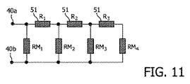
ある代替的な構成には、選択素子51として使われる追加的な抵抗器51が図11に示されるように配置されることもできる。図9の構成と比べての不利な点は、作動させられるべきでない放出機構30で散逸される電力が別の膜の作動の時点で変化するということである。
In an alternative configuration, an
追加的な抵抗器51は好ましくは、放出機構30の抵抗器と同じプロセスおよび同じ材料を使って作られる。これは両者の間の非常によいマッチングを可能にする。もちろん、それらは、散逸しなければならない電力に容易に耐えることができるように作られる必要がある。特に、ラダー中の最後の追加的抵抗器はやや高い散逸をもつことになる。ここでもまた、膜(すなわち放出機構30)の状態の検証が、簡単な電流または抵抗測定によってできる。
The
さらに、本発明の第二の実施形態のある変形によれば、非線形素子が選択素子51として提供されることも可能である。結果として得られる回路は並列に接続されることができる。これは、図13に示されている。そのような非線形抵抗器素子の一つの挙動は、図12におおまかに示されている。図12では、電流I対電圧Vの挙動が概略的に示されている(単位なしで)。放出機構30を流れる電流は今では、作動接点40a、40bにおける電圧に非線形に依存する。これは、線形抵抗器の使用に比べて、膜ごとのプログラミング電圧間のマージンを増す。非線形抵抗器やダイオードといったさまざまな型の非線形素子が使用できる。非線形抵抗器は、低コストの堆積(deposition)処理を使って作成でき、そうした処理は本発明の装置の生産工程によく適合する。たとえば、二つの異なる金属層を接続することによって、ショトキー・ダイオードが形成できる。
Furthermore, according to a variant of the second embodiment of the present invention, a non-linear element can also be provided as the
放出機構30の経路中に非線形に振る舞う選択素子51を挿入することによって、それより下ではほとんど電流が流れない閾値が効果的に設定される。経路中に二つ以上のそのような抵抗器を挿入することによって、各膜または各放出機構30は、図14に示されるように個別の閾値電圧をもつことができる。結果は、さまざまな作動電圧がより小さな範囲にまたがるということである。さらに、それらの電圧はそのような電圧範囲にわたってより均等に離間される。これは、より多数の膜が第一および第二の作動接点40a、40bに接続されることを許容する。この挙動は図14に示されている。ここでもまた、第一の電力レベル61と第二の電力レベル62が散逸される電力60ともども、第一および第二の作動接点40a、40bの間に加えられる作動信号45の関数として示されている。
By inserting the
本発明の第二の実施形態のさらなる変形では、容量性の選択素子52(図15参照)または誘導性の選択素子53(図16参照)が概略的に示されている。適正な放出機構30の選択は、作動信号45の異なる電圧に基づくのではなく、異なる周波数に基づく。直列キャパシタは、放出機構30における散逸を、作動信号45の周波数に依存させる。周波数の関数としてのインピーダンス測定は、膜の状態の検証を許容する。使用されるべき周波数は、異なる静電容量について製造コストを制限するために、かなり高い。キャパシタの代わりに、インダクタも選択素子として使用されることができる。
In a further variant of the second embodiment of the invention, a capacitive selection element 52 (see FIG. 15) or an inductive selection element 53 (see FIG. 16) is schematically shown. The selection of the
Claims (19)
・前記第二の数の作動接点のうちの少なくとも第一の作動接点と第二の作動接点との間に作動信号を加え、それにより前記第一の数の画室のうちの一つの画室から物質を放出するステップを有する、方法。 A method for controllably releasing a predetermined amount of a substance from at least one compartment using an apparatus, the apparatus comprising a first number of compartments in a substrate, each compartment having at least one release mechanism. And the device further comprises a second number of actuating contacts, wherein the first number is greater than the second number, each of the actuating contacts in or on the substrate, Having at least one conductor path electrically connected to at least one compartment, the working contact forming a mesh-like structure in or on the substrate, the method comprising:
Applying an actuation signal between at least a first actuation contact and a second actuation contact of said second number of actuation contacts, thereby causing a substance from one of said first number of compartments Releasing the method.
・前記第二の数の作動接点のうちの少なくとも第一の作動接点と第二の作動接点との間に作動信号を加え、それにより前記第一の数の画室のうちの一つの画室から物質を放出するステップを有する、方法。 A method for controllably releasing a predetermined amount of a substance from at least one compartment using an apparatus, the apparatus comprising a first number of compartments in a substrate, each compartment having at least one release mechanism. And the device further comprises a second number of actuating contacts, wherein the first number is greater than the second number, each of the actuating contacts in or on the substrate, At least one conductor path electrically connected to at least one compartment, the one compartment depending on an actuation signal between the first actuation contact and the second actuation contact; Activated, the method is:
Applying an actuation signal between at least a first actuation contact and a second actuation contact of said second number of actuation contacts, thereby causing a substance from one of said first number of compartments Releasing the method.
19. A method according to claim 18, wherein the activation signal is adapted to voltage and / or frequency depending on the compartment to be activated.
Applications Claiming Priority (2)
| Application Number | Priority Date | Filing Date | Title |
|---|---|---|---|
| EP06113537 | 2006-05-05 | ||
| PCT/IB2007/051501 WO2007129240A1 (en) | 2006-05-05 | 2007-04-24 | Device and method for the controlled release of a predefined quantity of a substance |
Publications (2)
| Publication Number | Publication Date |
|---|---|
| JP2009536064A true JP2009536064A (en) | 2009-10-08 |
| JP2009536064A5 JP2009536064A5 (en) | 2011-11-24 |
Family
ID=38512606
Family Applications (1)
| Application Number | Title | Priority Date | Filing Date |
|---|---|---|---|
| JP2009508566A Pending JP2009536064A (en) | 2006-05-05 | 2007-04-24 | Apparatus and method for controlled release of a quantity of a substance |
Country Status (5)
| Country | Link |
|---|---|
| US (1) | US20090131918A1 (en) |
| EP (1) | EP2024999A1 (en) |
| JP (1) | JP2009536064A (en) |
| CN (1) | CN101438410A (en) |
| WO (1) | WO2007129240A1 (en) |
Families Citing this family (2)
| Publication number | Priority date | Publication date | Assignee | Title |
|---|---|---|---|---|
| KR102658425B1 (en) * | 2016-01-11 | 2024-04-17 | 사이키 메디컬 엘티디. | personal vaporizer |
| US11285307B2 (en) | 2016-02-19 | 2022-03-29 | University Of Florida Research Foundation, Incorporated | Drug delivery integrated circuit (IC) and system |
Citations (2)
| Publication number | Priority date | Publication date | Assignee | Title |
|---|---|---|---|---|
| WO2004071487A2 (en) * | 2002-08-16 | 2004-08-26 | Microchips, Inc. | Controlled release device and method |
| WO2006026768A1 (en) * | 2004-09-01 | 2006-03-09 | Microchips, Inc. | Multi-cap reservoir devices for controlled release or exposure of reservoir contents |
Family Cites Families (5)
| Publication number | Priority date | Publication date | Assignee | Title |
|---|---|---|---|---|
| US5797898A (en) * | 1996-07-02 | 1998-08-25 | Massachusetts Institute Of Technology | Microchip drug delivery devices |
| US7070590B1 (en) * | 1996-07-02 | 2006-07-04 | Massachusetts Institute Of Technology | Microchip drug delivery devices |
| AU770395B2 (en) | 1999-11-17 | 2004-02-19 | Boston Scientific Limited | Microfabricated devices for the delivery of molecules into a carrier fluid |
| EP1443463A4 (en) * | 2001-10-29 | 2006-02-15 | Sharp Kk | Cellular terminal, method for creating animation on cellular terminal, and animation creation system. |
| WO2004033034A1 (en) * | 2002-10-04 | 2004-04-22 | Microchips, Inc. | Medical device for neural stimulation and controlled drug delivery |
-
2007
- 2007-04-24 JP JP2009508566A patent/JP2009536064A/en active Pending
- 2007-04-24 US US12/299,128 patent/US20090131918A1/en not_active Abandoned
- 2007-04-24 CN CNA2007800161232A patent/CN101438410A/en active Pending
- 2007-04-24 EP EP07735625A patent/EP2024999A1/en not_active Withdrawn
- 2007-04-24 WO PCT/IB2007/051501 patent/WO2007129240A1/en not_active Ceased
Patent Citations (2)
| Publication number | Priority date | Publication date | Assignee | Title |
|---|---|---|---|---|
| WO2004071487A2 (en) * | 2002-08-16 | 2004-08-26 | Microchips, Inc. | Controlled release device and method |
| WO2006026768A1 (en) * | 2004-09-01 | 2006-03-09 | Microchips, Inc. | Multi-cap reservoir devices for controlled release or exposure of reservoir contents |
Also Published As
| Publication number | Publication date |
|---|---|
| CN101438410A (en) | 2009-05-20 |
| EP2024999A1 (en) | 2009-02-18 |
| WO2007129240A1 (en) | 2007-11-15 |
| US20090131918A1 (en) | 2009-05-21 |
Similar Documents
| Publication | Publication Date | Title |
|---|---|---|
| ES2274472T3 (en) | FLUID MICROVALVULA OF OPENING BY ELECTRIC OPERATION. | |
| US20100063485A1 (en) | Device for the controlled release of a predefined quantity of a substance | |
| EP3221049B1 (en) | Microbubble generator device, systems and method to fabricate | |
| US8202566B2 (en) | Method of producing an electronic unit having a polydimethylsiloxane substrate and circuit lines | |
| US20140115714A1 (en) | Method and apparatus for prevention of tampering and unauthorized extraction of information from microdevices | |
| US8480974B2 (en) | Device for controlling the flow of fluids through microfluidic channels | |
| US7800279B2 (en) | Thermo-buckled micro actuation unit made of polymer of high thermal expansion coefficient | |
| Bhuyan et al. | 2D and 3D structuring of freestanding metallic wires enabled by room-temperature welding for soft and stretchable electronics | |
| US11433394B2 (en) | Flow control device | |
| JP2009536064A (en) | Apparatus and method for controlled release of a quantity of a substance | |
| JP2009538671A (en) | Equipment for controlled release of substances | |
| JP2009536064A5 (en) | ||
| US10343162B2 (en) | Reconfigurable microfluidic device and method of manufacturing the same | |
| US20090099553A1 (en) | Device for the controlled release of a substance and method of releasing a substance | |
| DE19739722A1 (en) | Rich fluid microengineered system | |
| CN101212994A (en) | Devices for the controlled release of predetermined quantities of substances | |
| US20080221556A1 (en) | Device For the Controlled Release of a Predefined Quantity of a Substance | |
| US12036792B2 (en) | Electrohydrodynamic print head with structured feed layer | |
| WO2006066541A1 (en) | Electronically controllable micropump based on hydrogel | |
| WO2007042961A2 (en) | Device for controlled release of chemical molecules |
Legal Events
| Date | Code | Title | Description |
|---|---|---|---|
| A621 | Written request for application examination |
Free format text: JAPANESE INTERMEDIATE CODE: A621 Effective date: 20100421 |
|
| A521 | Request for written amendment filed |
Free format text: JAPANESE INTERMEDIATE CODE: A523 Effective date: 20081105 |
|
| A521 | Request for written amendment filed |
Free format text: JAPANESE INTERMEDIATE CODE: A523 Effective date: 20081105 |
|
| A977 | Report on retrieval |
Free format text: JAPANESE INTERMEDIATE CODE: A971007 Effective date: 20120209 |
|
| A131 | Notification of reasons for refusal |
Free format text: JAPANESE INTERMEDIATE CODE: A131 Effective date: 20120214 |
|
| A02 | Decision of refusal |
Free format text: JAPANESE INTERMEDIATE CODE: A02 Effective date: 20120710 |