JP2009266277A - Information recording unit and recording condition adjusting method - Google Patents
Information recording unit and recording condition adjusting method Download PDFInfo
- Publication number
- JP2009266277A JP2009266277A JP2008112405A JP2008112405A JP2009266277A JP 2009266277 A JP2009266277 A JP 2009266277A JP 2008112405 A JP2008112405 A JP 2008112405A JP 2008112405 A JP2008112405 A JP 2008112405A JP 2009266277 A JP2009266277 A JP 2009266277A
- Authority
- JP
- Japan
- Prior art keywords
- recording
- power
- signal quality
- reproduction signal
- recorded
- Prior art date
- Legal status (The legal status is an assumption and is not a legal conclusion. Google has not performed a legal analysis and makes no representation as to the accuracy of the status listed.)
- Pending
Links
- 238000000034 method Methods 0.000 title claims description 60
- 230000003287 optical effect Effects 0.000 claims abstract description 94
- 238000010438 heat treatment Methods 0.000 claims description 125
- 238000005259 measurement Methods 0.000 claims description 31
- 230000008859 change Effects 0.000 description 35
- 238000012360 testing method Methods 0.000 description 25
- 230000007613 environmental effect Effects 0.000 description 19
- 230000001133 acceleration Effects 0.000 description 18
- 238000012545 processing Methods 0.000 description 10
- 238000010586 diagram Methods 0.000 description 9
- 230000003044 adaptive effect Effects 0.000 description 8
- 230000015572 biosynthetic process Effects 0.000 description 6
- 238000011156 evaluation Methods 0.000 description 6
- 230000008569 process Effects 0.000 description 5
- 230000004044 response Effects 0.000 description 4
- 239000000758 substrate Substances 0.000 description 4
- 238000001514 detection method Methods 0.000 description 3
- 238000011045 prefiltration Methods 0.000 description 3
- 238000007476 Maximum Likelihood Methods 0.000 description 2
- 238000004364 calculation method Methods 0.000 description 2
- 238000012937 correction Methods 0.000 description 2
- 230000000694 effects Effects 0.000 description 2
- 230000010354 integration Effects 0.000 description 2
- 238000004519 manufacturing process Methods 0.000 description 2
- 230000002093 peripheral effect Effects 0.000 description 2
- 230000002159 abnormal effect Effects 0.000 description 1
- 239000000654 additive Substances 0.000 description 1
- 230000000996 additive effect Effects 0.000 description 1
- 230000002411 adverse Effects 0.000 description 1
- 238000013459 approach Methods 0.000 description 1
- 230000015556 catabolic process Effects 0.000 description 1
- 238000001816 cooling Methods 0.000 description 1
- 238000006731 degradation reaction Methods 0.000 description 1
- 238000013461 design Methods 0.000 description 1
- 230000006866 deterioration Effects 0.000 description 1
- 238000005516 engineering process Methods 0.000 description 1
- 239000000284 extract Substances 0.000 description 1
- 238000001914 filtration Methods 0.000 description 1
- 230000001771 impaired effect Effects 0.000 description 1
- 230000006872 improvement Effects 0.000 description 1
- 230000010365 information processing Effects 0.000 description 1
- 238000012986 modification Methods 0.000 description 1
- 230000004048 modification Effects 0.000 description 1
- 229920000515 polycarbonate Polymers 0.000 description 1
- 239000004417 polycarbonate Substances 0.000 description 1
- 238000013441 quality evaluation Methods 0.000 description 1
- 239000000126 substance Substances 0.000 description 1
- 230000001360 synchronised effect Effects 0.000 description 1
- 230000000007 visual effect Effects 0.000 description 1
Images








Classifications
-
- G—PHYSICS
- G11—INFORMATION STORAGE
- G11B—INFORMATION STORAGE BASED ON RELATIVE MOVEMENT BETWEEN RECORD CARRIER AND TRANSDUCER
- G11B7/00—Recording or reproducing by optical means, e.g. recording using a thermal beam of optical radiation by modifying optical properties or the physical structure, reproducing using an optical beam at lower power by sensing optical properties; Record carriers therefor
- G11B7/12—Heads, e.g. forming of the optical beam spot or modulation of the optical beam
- G11B7/125—Optical beam sources therefor, e.g. laser control circuitry specially adapted for optical storage devices; Modulators, e.g. means for controlling the size or intensity of optical spots or optical traces
- G11B7/126—Circuits, methods or arrangements for laser control or stabilisation
- G11B7/1267—Power calibration
-
- G—PHYSICS
- G11—INFORMATION STORAGE
- G11B—INFORMATION STORAGE BASED ON RELATIVE MOVEMENT BETWEEN RECORD CARRIER AND TRANSDUCER
- G11B7/00—Recording or reproducing by optical means, e.g. recording using a thermal beam of optical radiation by modifying optical properties or the physical structure, reproducing using an optical beam at lower power by sensing optical properties; Record carriers therefor
- G11B2007/0003—Recording, reproducing or erasing systems characterised by the structure or type of the carrier
- G11B2007/0006—Recording, reproducing or erasing systems characterised by the structure or type of the carrier adapted for scanning different types of carrier, e.g. CD & DVD
-
- G—PHYSICS
- G11—INFORMATION STORAGE
- G11B—INFORMATION STORAGE BASED ON RELATIVE MOVEMENT BETWEEN RECORD CARRIER AND TRANSDUCER
- G11B7/00—Recording or reproducing by optical means, e.g. recording using a thermal beam of optical radiation by modifying optical properties or the physical structure, reproducing using an optical beam at lower power by sensing optical properties; Record carriers therefor
- G11B7/004—Recording, reproducing or erasing methods; Read, write or erase circuits therefor
- G11B7/0045—Recording
- G11B7/00456—Recording strategies, e.g. pulse sequences
Landscapes
- Physics & Mathematics (AREA)
- Optics & Photonics (AREA)
- Optical Recording Or Reproduction (AREA)
- Optical Head (AREA)
Abstract
Description
本発明は、情報記録装置及び記録条件調整方法に関し、更に詳しくは、光ビーム照射によりマークが形成される光学的情報記録媒体に記録を行う情報記録装置、及び、そのような情報記録装置における記録時の記録条件調整方法に関する。 The present invention relates to an information recording apparatus and a recording condition adjusting method, and more specifically, an information recording apparatus for recording on an optical information recording medium on which a mark is formed by light beam irradiation, and recording in such an information recording apparatus. The present invention relates to a method for adjusting recording conditions.
光ディスク装置(光学的情報記録再生装置)は、レーザ光を用いて、光ディスクに記録された情報の読出しと、光ディスクへの情報の書込みを行うことができる。光ディスク装置は、例えば、情報処理装置の周辺機器や、AV(Audio Visual)機器などに用いられる。光ディスク装置は、光ディスクの記録層にレーザ光を照射し、その記録層を構成する物質の特性を変化させることで、光ディスクに記録マークを形成する。光ディスク装置は、記録データに基づいた記録マークを光ディスクに形成し、情報を記録する。 An optical disc apparatus (optical information recording / reproducing apparatus) can read information recorded on an optical disc and write information on the optical disc using a laser beam. The optical disk device is used, for example, for peripheral devices of information processing devices, AV (Audio Visual) devices, and the like. An optical disc apparatus irradiates a recording layer of an optical disc with a laser beam and changes the characteristics of a substance constituting the recording layer, thereby forming a recording mark on the optical disc. The optical disc apparatus records information by forming a recording mark on the optical disc based on the recording data.
記録データに対応した記録マークを適切に形成するためには、記録層に照射するレーザ光のパワー、すなわち、記録層に加えられる熱のコントロールが重要である。例えば、特定の記録マークを形成する際に、記録層に加える熱量が少ないと、記録層に十分な記録マークを形成することができない。逆に、記録層に加える熱量が多すぎると、記録マークの形状が不適切になる。また、熱量が多い場合は、形成した記録マークが、隣接する他の記録マークの形成に悪影響を与えることもある。 In order to appropriately form a recording mark corresponding to the recording data, it is important to control the power of the laser beam applied to the recording layer, that is, the heat applied to the recording layer. For example, when a specific recording mark is formed, if the amount of heat applied to the recording layer is small, a sufficient recording mark cannot be formed on the recording layer. On the other hand, when the amount of heat applied to the recording layer is too large, the shape of the recording mark becomes inappropriate. Further, when the amount of heat is large, the formed recording mark may adversely affect the formation of other adjacent recording marks.
従って、光ディスク装置では、マーク形成時のレーザ光の出力を適切に制御することが非常に重要である。レーザ光の制御は、記録ストラテジと呼ばれる波形形状を変更することによって行われる。記録ストラテジが示す波形は、振幅によってピーク(記録)パワー、バイアスパワーなどの出力レベルを表し、記録用レーザパルスのパルス幅(時間方向)によって、マーク形成のレーザ光の照射時間を表している。 Therefore, in an optical disc apparatus, it is very important to appropriately control the output of laser light when forming a mark. The laser light is controlled by changing the waveform shape called a recording strategy. The waveform indicated by the recording strategy represents the output level such as peak (recording) power and bias power by the amplitude, and represents the irradiation time of the mark forming laser beam by the pulse width (time direction) of the recording laser pulse.
記録ストラテジにはいろいろな種類があり、記録するメディアに応じて、パワーレベルやパルス形状などを変える場合がある。例えば、1回だけ記録可能な追記型光ディスクであるDVD−R(Digital Versatile Disk Recordable)などでは、矩形型の記録ストラテジが用いられる。また、繰り返し書換えが可能な光ディスクであるDVD−RW(Digital Versatile Disk ReWritable)などでは、マルチパス型の記録パルスが用いられる。 There are various types of recording strategies, and the power level and pulse shape may be changed depending on the recording medium. For example, in a DVD-R (Digital Versatile Disk Recordable) that is a write-once optical disc that can be recorded only once, a rectangular recording strategy is used. In addition, multi-pass recording pulses are used in DVD-RW (Digital Versatile Disk ReWritable), which is an optical disk that can be rewritten repeatedly.
図21(a)〜(f)に、記録するパタンと、各種記録ストラテジとを示す。同図(b)〜(f)に示す記録ストラテジは、同図(a)に示すパタンを形成する際に用いられる記録ストラテジである。同図(b)は、2値のパワーレベルを持つパルストレイン型の記録ストラテジを示している。この記録ストラテジでは、マークに対応した位置で、バイアスパワーPbとピークパワーPwとの2値のパワーレベルを持つレーザ光のパルスを、複数回照射する。同図(c)は、単純矩形型の記録ストラテジを示している。この記録ストラテジでは、マークに対応した位置で、レーザ光のパワーを、バイアスパワーPbからピークパワーPwに上げる。 21A to 21F show patterns to be recorded and various recording strategies. The recording strategies shown in FIGS. 5B to 5F are recording strategies used when forming the pattern shown in FIG. FIG. 2B shows a pulse train type recording strategy having a binary power level. In this recording strategy, a pulse of laser light having a binary power level of bias power Pb and peak power Pw is irradiated a plurality of times at a position corresponding to the mark. FIG. 2C shows a simple rectangular recording strategy. In this recording strategy, the laser beam power is increased from the bias power Pb to the peak power Pw at a position corresponding to the mark.
図21(d)は、先端を強調した矩形の記録ストラテジを示している。この記録ストラテジでは、記録マークに対応した位置でレーザ光のパワーをピークパワーPwに上げ、その後、パワーをピークパワーPwよりも低いミドルパワーPmに落として矩形の先端を強調している。同図(e)は、先頭と最後とを強調した矩形型の記録ストラテジである。この記録ストラテジでは、同図(d)の先端を強調した矩形の記録パワーにて、矩形の後端でレーザ光のパワーを再びピークパワーPwに上げ、矩形の先頭と最後とを強調している。 FIG. 21D shows a rectangular recording strategy with the tip emphasized. In this recording strategy, the power of the laser beam is raised to the peak power Pw at the position corresponding to the recording mark, and then the power is lowered to the middle power Pm lower than the peak power Pw to emphasize the rectangular tip. FIG. 4E shows a rectangular recording strategy in which the beginning and end are emphasized. In this recording strategy, at the rear end of the rectangle, the laser light power is increased again to the peak power Pw at the rectangular recording power with the leading end of FIG. .
図21(f)は、3値のパワーレベルを持つパルストレイン型の記録ストラテジである。この記録ストラテジでは、レーザ光のパワーレベルを、ボトムパワーPbtm、ピークパワーPw、及び、ボトムパワーとピークパワーとの間のレベルのパワーの3つのレベルで変化させる。ボトムパワーとピークパワーとの間のレベルのパワーは、スペースに対応して照射されるパワーであり、書換え可能媒体用では消去パワーPeと呼ばれる。これは、そのレベルのパワーのレーザ光は、以前に存在した記録マークを消去する作用があるからである。しかしながら、このスペースに対応して照射されるパワーを、総称として、バイアスパワーと称する場合もある。 FIG. 21F shows a pulse train type recording strategy having a ternary power level. In this recording strategy, the power level of the laser light is changed at three levels: bottom power Pbtm, peak power Pw, and power between the bottom power and peak power. The power at the level between the bottom power and the peak power is the power irradiated corresponding to the space, and is called erasing power Pe for a rewritable medium. This is because the laser beam with that level of power has the effect of erasing previously existing recording marks. However, the power irradiated corresponding to this space may be collectively referred to as bias power.
次世代DVDであるHD DVD(High Definition DVD)では、追記型のHD DVD−Rも、書換え可能型のHD DVD−RW又はHD DVD−RAMも、2倍速記録までは、主にマルチパス型の記録ストラテジを使用している。記録ストラテジは、光ディスクの記録再生性能に大きく影響する。このため、多くの記録ストラテジ調整手法が存在している。 In the high definition DVD (HD DVD) that is the next generation DVD, both the write-once type HD DVD-R and the rewritable type HD DVD-RW or HD DVD-RAM are mainly multi-pass types up to double speed recording. You are using a recording strategy. The recording strategy greatly affects the recording / reproducing performance of the optical disc. For this reason, many recording strategy adjustment methods exist.
続いて、光ディスクへの記録に必要な記録パラメータの調整に使用される性能指標について説明する。ここでは、記録時パワーの調整を例とする。ブランクディスクは、そのディスクの一部に、記録パワーの調整に使用できる領域(エリア)を持っている。光ディスク装置は、その領域を使用して、適宜、記録時パワーの調整を行う。 Next, performance indexes used for adjusting recording parameters necessary for recording on an optical disc will be described. Here, adjustment of recording power is taken as an example. The blank disk has an area (area) that can be used for adjusting the recording power in a part of the disk. The optical disc apparatus uses the area to adjust the recording power as appropriate.
光学的情報記録再生装置は、ブランクディスクが装填されると、そのディスクから、ディスクの種類や媒体メーカ名等の情報を読み出す。光学的情報記録再生装置は、読み出した情報に基づいて、装填された媒体に応じた記録ストラテジや、媒体から読み出した情報が示す奨励記録ストラテジを用いて、OPC(Optimum Power Control)と言われる記録パワーの調整を行う。記録パワーの調整では、媒体から読み出した情報を使用せずに、装置が各媒体に対応させてあらかじめ保持している情報を利用する場合もある。 When a blank disc is loaded, the optical information recording / reproducing apparatus reads information such as the disc type and medium manufacturer name from the disc. The optical information recording / reproducing apparatus uses a recording strategy corresponding to a loaded medium and a recommended recording strategy indicated by the information read from the medium based on the read information, and is called OPC (Optimum Power Control) recording. Adjust the power. In the adjustment of the recording power, there is a case where information stored in advance by the apparatus corresponding to each medium is used without using information read from the medium.
記録パワーの調整方法としては、長いマークと短いマークの再生振幅により得られるアシンメトリを検査してβ値を求めるβ法や、記録マーク振幅の飽和の程度から判断するγ法などが知られている。一般的に、DVD−Rではβ法が使用され、DVD−RWやDVD+RWではγ法が使用される。 As a method for adjusting the recording power, a β method for obtaining a β value by inspecting an asymmetry obtained by reproducing amplitudes of a long mark and a short mark, and a γ method for judging from the degree of saturation of the recording mark amplitude are known. . In general, the β method is used for DVD-R, and the γ method is used for DVD-RW and DVD + RW.
β法では、短マークを再生して得られた基準値Refと、長マークのピークレベル及びボトムレベルとに基づいて、β値を算出する。図22に、β値の算出例を示す。この例では、長マークは11Tマークであり、短マークは3Tマークである。基準値Refは、3Tマーク再生振幅の中心に設定されている。3Tマークの再生波形から基準値Refを求め、その基準値Refと11Tマークのピークレベルとの差分A、及び、基準値Refと11Tマークのボトムレベルとの差分Bを求める。その後、下記式1により、β値を算出する。
β=0.5×(A−B)/(A+B) (1)
In the β method, the β value is calculated based on the reference value Ref obtained by reproducing the short mark and the peak level and bottom level of the long mark. FIG. 22 shows an example of β value calculation. In this example, the long mark is an 11T mark and the short mark is a 3T mark. The reference value Ref is set at the center of the 3T mark reproduction amplitude. A reference value Ref is obtained from the reproduction waveform of the 3T mark, and a difference A between the reference value Ref and the peak level of the 11T mark and a difference B between the reference value Ref and the bottom level of the 11T mark are obtained. Thereafter, the β value is calculated by the following formula 1.
β = 0.5 × (A−B) / (A + B) (1)
β値は、各パタンの最小値、最大値、平均レベル(平均電圧)等の信号レベルを使用して算出される。β値は、最大振幅と最小振幅の中心のずれを表しており、アシンメトリと同義として用いられる。また、β値は、記録信号品質の評価指標であるジッタσやエラー数などの信号品質指標との相関がある。β値は、値そのものは性能を保証するものではなく、β値と性能との絶対値指標、例えば、エラー数やエラーレート、ジッタ値などとの対応を取った上で、目標として用いられる。一般的に、ジッタσが15%以上になると、エラー訂正処理を行ってもエラーが訂正できなくなるので、ジッタσを15%以下にするように、記録パラメータの調整を行う必要がある。 The β value is calculated using signal levels such as the minimum value, maximum value, and average level (average voltage) of each pattern. The β value represents the deviation between the center of the maximum amplitude and the minimum amplitude, and is used synonymously with asymmetry. Also, the β value has a correlation with a signal quality index such as jitter σ and the number of errors, which is an evaluation index of the recording signal quality. The β value itself does not guarantee the performance, and is used as a target after taking correspondence between the absolute value index of the β value and the performance, for example, the number of errors, error rate, jitter value, and the like. Generally, when the jitter σ is 15% or more, the error cannot be corrected even if error correction processing is performed. Therefore, it is necessary to adjust the recording parameters so that the jitter σ is 15% or less.
また、高密度化された次世代DVDであるHD DVDにおいては、PRML(Partial Response Maximum Likelihood)検出が用いられる。HD DVDでは、ジッタ自体の測定が困難である。そのため、HD DVDにおける性能指標には、PRSNR(Partial Response Signal to Noise Ratio)という性能指標が導入されている(例えば、非特許文献1参照)。PRSNRは、ジッタに代わる信号品質評価指標として用いられる。PRSNRは、PRML検出におけるSNR値である。PRSNRは、エラーレートへの換算も可能で、この値が高いほど、信号品質は優れていることを意味する。装置での運用に際しては、PRSNRが15以上の性能が要求されることが一般に知られている。なお、再生波形の品質を評価する他の手法には、直接にエラーレートやエラーバイト数を求める手法もある。これらは、性能の絶対値を示す指標である。エラーレートやジッタは、値が低い(小さい)ほど、性能がよい。 In addition, in the HD DVD, which is a next-generation DVD having a higher density, PRML (Partial Response Maximum Likelihood) detection is used. With HD DVD, it is difficult to measure jitter itself. Therefore, a performance index called PRSNR (Partial Response Signal to Noise Ratio) has been introduced as a performance index in HD DVD (for example, see Non-Patent Document 1). The PRSNR is used as a signal quality evaluation index instead of jitter. PRSNR is an SNR value in PRML detection. The PRSNR can be converted into an error rate. The higher this value, the better the signal quality. It is generally known that a performance with a PRSNR of 15 or more is required for operation in an apparatus. As another method for evaluating the quality of the reproduced waveform, there is a method for directly obtaining the error rate and the number of error bytes. These are indices indicating the absolute value of performance. The lower the error rate and jitter, the better the performance.
ここで、記録可能型光ディスクに求められる特性として、周囲の環境によって光ディスク自身やその特性が変化しない特性がある。これは、耐候性と呼ばれる。耐候性には、いくつかの特性があり、アーカイバル特性(アーカイバルライフ)、シェルフ特性(シェルライフ)、アーカイバルオーバーライト特性(オーバーライトシェルフ)などがある。これら特性の評価は、記録層に情報が記録されていない未記録、又は、情報が既に記録された既記録の光ディスクに、熱や湿度を強制的に加える環境加速試験により行う。 Here, as a characteristic required for a recordable optical disk, there is a characteristic that the optical disk itself and its characteristic do not change depending on the surrounding environment. This is called weather resistance. The weather resistance has several characteristics, such as archival characteristics (archival life), shelf characteristics (shell life), and archival overwrite characteristics (overwrite shelf). The evaluation of these characteristics is performed by an environmental acceleration test in which heat or humidity is forcibly applied to an unrecorded optical disc in which no information is recorded in the recording layer or an already recorded optical disc in which information is already recorded.
各耐候性特性に関して説明する。アーカイバル特性は、記録されたデータの保存性やその安定性に関する特性で、一度記録されたデータがどの程度の期間安定に存在できるかを決定する特性である。アーカイバル特性が劣化すると、記録したデータの再生ができなくなる。シェルフ特性は、経時変化や環境変化に対し、未記録部分に対し記録条件がどの程度の期間変化せずに存在するかを決める特性である。シェルフ特性が劣化すると、未記録の部分に記録しても、良好な記録ができなくなる。アーカイバルオーバーライト特性は、既に1回以上記録した部分に、どの程度の期間良好にオーバーライト(書換え)ができるかを決定する特性である。アーカイバルオーバーライト特性が劣化すると、良好にオーバーライト記録することができなくなる。 Each weather resistance characteristic is demonstrated. The archival characteristic is a characteristic relating to storability and stability of recorded data, and is a characteristic that determines how long the recorded data can exist stably. When the archival characteristics deteriorate, the recorded data cannot be reproduced. The shelf characteristic is a characteristic that determines how long the recording condition does not change with respect to an unrecorded portion with respect to a change with time or an environmental change. If the shelf characteristics deteriorate, good recording cannot be performed even if recording is performed on an unrecorded portion. The archival overwrite characteristic is a characteristic that determines how long a good overwrite (rewrite) can be performed on a portion that has already been recorded once or more. If the archival overwrite characteristic is deteriorated, it becomes impossible to perform good overwrite recording.
これまでに、耐候性を高めるための技術がいくつか提案されている。特許文献1には、媒体に関し、記録膜に添加物を入れる手法が記載されている。特許文献2には、装置に関し、光ディスクに経時変化が生じている場合は、記録ジッタが最小となるようにライトストラテジを補正する技術が記載されている。特許文献3では、2種類の特定パタンを記録し、記録した領域を再生する。特許文献3では、記録した領域を再生したときに、各特定パタンに対応するアシンメトリ値の差が|0.02|以下になるように記録照射パワーを定めることで、シェルフ特性が高い記録条件を選定する。
So far, several techniques for improving weather resistance have been proposed. Patent Document 1 describes a method of adding an additive to a recording film with respect to a medium.
特許文献4では、テスト領域にDCパワーを変えて記録を行い、記録した領域を再生する。パワー変化に対して、反射率変化が最も大きなパワー値Pdを求め、これに、あらかじめ求めてある係数を乗算することで、ピークパワーPpとバイアスパワーPbとを決定する。特許文献4には、この動作を、光ディスクの記録条件が変化する要因が発生した場合に実施する旨が記載されている。特許文献5では、記録を行った後に、通常再生するパワーよりも高い再生パワーで少なくとも1回再生を行う。特許文献5には、この動作を行うことで、相変化光ディスクのアーカイバルオーバーライト特性の抑制が可能である旨が記載されている。
In
特許文献6には、波長780nm対応の追記型有機色素記録媒体の経時変化後のエラー率増加を防止する記録条件設定法が記載さている。特許文献6には、実験により、エラー率を最小にさせるレーザ光照射パワーの値の0.5〜0.93倍のレーザ照射パワーにより記録させることが記載されている。また、アーカイバル特性測定のために、仮想環境試験により媒体を暴露した後に、エラー率を測定していることが記載されている。
耐候性評価には環境加速試験が用いられる。その環境加速試験には、特別な設備が必要である。また、環境加速試験は、例えば数百時間を超える多大な時間を要する。このため、耐候性評価を、記録再生する実際の装置で行うことができないということが問題となる。これまでに提案されている技術の多くは、記録特性としてのシェルフ特性やアーカイバルオーバーライト特性に対応するものである。一方、耐候性として重要度が高い保存安定性であるアーカイバル特性の確保に対応した技術は、媒体の特性改善に依存しており、装置としてはほとんど対策はなされていない。 An environmental acceleration test is used for the weather resistance evaluation. The environmental acceleration test requires special equipment. Moreover, the environmental acceleration test requires a great amount of time exceeding, for example, several hundred hours. For this reason, it is a problem that the weather resistance evaluation cannot be performed with an actual apparatus for recording and reproducing. Many of the techniques that have been proposed so far correspond to the shelf characteristics and archival overwrite characteristics as recording characteristics. On the other hand, the technology corresponding to ensuring the archival characteristics, which are storage stability, which is highly important as weather resistance, relies on the improvement of the characteristics of the medium, and little measures are taken as the apparatus.
更に、近年の光ディスクは高密度化が進み、記録に関わる記録時パワーを含め、記録時のパラメータ調整は高い精度が必要になってきている。また、記録再生装置では、波長405nm近傍のレーザ光を使用するものも出現しており、それに併せて媒体特性も変化している。このため、アーカイバル特性の確保について、既に存在する手法は必ずしも適用できるとは限らない状況にある。特に、有機色素を記録層に用いる媒体は、特性の波長依存性が高いことが知られており、既に存在する手法が必ずしも当てはまらない傾向は顕著となっている。 Furthermore, recent optical discs have been increased in density, and parameter adjustment during recording, including recording power related to recording, requires high accuracy. In addition, some recording / reproducing apparatuses that use laser light having a wavelength of about 405 nm have appeared, and the medium characteristics have changed accordingly. For this reason, the existing method is not necessarily applicable to securing the archival characteristics. In particular, a medium using an organic dye for the recording layer is known to have a high wavelength dependency of characteristics, and the tendency that the existing method does not always apply is remarkable.
本発明は、アーカイバル特性が確保しやすい記録条件を、簡易に短時間で選定可能な記録条件調整方法、及び、情報記録装置を提供することを目的とする。 An object of the present invention is to provide a recording condition adjusting method and an information recording apparatus capable of easily and quickly selecting recording conditions in which archival characteristics can be easily secured.
上記目的を達成するために、本発明の記録条件調整方法は、光ビーム照射によりマークが形成される光学的情報記録媒体に記録を行う情報記録装置における記録条件を調整する方法であって、前記光学的情報記録媒体に記録された記録パタン列を加熱する加熱ステップと、前記加熱ステップで加熱した記録パタン列を再生し、再生信号品質を測定する品質測定ステップと、前記測定された再生信号品質に基づいて、情報記録時の記録条件を決定する条件決定ステップとを有することを特徴とする。 In order to achieve the above object, the recording condition adjusting method of the present invention is a method for adjusting a recording condition in an information recording apparatus for recording on an optical information recording medium on which a mark is formed by light beam irradiation, A heating step for heating the recording pattern train recorded on the optical information recording medium, a quality measuring step for reproducing the recording pattern train heated in the heating step and measuring a reproduction signal quality, and the measured reproduction signal quality And a condition determining step for determining a recording condition at the time of recording information.
本発明の情報記録装置は、光ビーム照射によりマークが形成される光学的情報記録媒体に記録を行う情報記録装置であって、前記光学的情報記録媒体に記録された記録パタン列を加熱し、該加熱した記録パタン列を再生して再生信号品質を測定し、該測定された再生信号品質に基づいて情報記録時の記録条件を決定するパラメータ調整器を備えることを特徴とする。 An information recording apparatus of the present invention is an information recording apparatus for recording on an optical information recording medium on which a mark is formed by light beam irradiation, and heats a recording pattern row recorded on the optical information recording medium, A parameter adjuster is provided that reproduces the heated recording pattern sequence to measure the reproduction signal quality, and determines recording conditions at the time of recording information based on the measured reproduction signal quality.
本発明の記録条件調整方法、及び、情報記録装置は、アーカイバル特性が確保しやすい記録条件を、簡易に短時間で選定することができる。 The recording condition adjusting method and the information recording apparatus of the present invention can easily and quickly select a recording condition that ensures archival characteristics.
以下、図面を参照して、本発明の実施の形態を詳細に説明する。図1は、本発明の第1実施形態の情報記録再生装置を示している。情報記録再生装置100は、RF回路103、復調器104、システムコントローラ105、変調器106、LDドライバ107、サーボコントローラ108、スピンドル駆動系109、及び、光ヘッド120を有する。光ディスク114は、記録が可能なメディア、例えば、1度だけ記録が可能な追記型メディアである。情報記録再生装置100は、光ディスク114に対する情報記録、及び、光ディスク114からの情報再生を行う。
Hereinafter, embodiments of the present invention will be described in detail with reference to the drawings. FIG. 1 shows an information recording / reproducing apparatus according to a first embodiment of the present invention. The information recording / reproducing
光ヘッド120は、レーザダイオード(LD)121、受光部122、及び、ビームスプリッタ125を含む。レーザダイオード121は、光ディスク114の記録/再生に用いる光を出射する。ビームスプリッタ125は、レーザダイオード121側から入射する光を、光ディスク114側に反射する。ビームスプリッタ125を反射した光は、対物レンズによって、光ディスク114の記録層に集光される。
The
光ディスク114の記録層に集光した光は、光ディスク114で反射し、ビームスプリッタ125に入射する。ビームスプリッタ125は、光ディスク114側から入射する光を、受光部122側に透過する。受光部122は、ビームスプリッタ125を透過した光を電気信号に変換する。受光部122によって変換された電気信号は、プリアンプで増幅され、RF回路103に供給される。
The light condensed on the recording layer of the optical disc 114 is reflected by the optical disc 114 and enters the
スピンドル駆動系109は、光ディスク114を回転させる。RF回路103は、入力信号に基づいて2値化信号の生成を行う。また、RF回路103は、入力信号にフィルタリング等の処理を行って信号品質の測定を行い、信号品質を示す値を、システムコントローラ105に出力する。復調器104は、RF回路103で生成された2値化信号に基づいて、所定の復調規則に従ってデータを復調し、システムコントローラ105に出力する。
The
変調器106は、記録すべき信号を、所定の変調規則で変調する。LDドライバ107は、変調器106の出力信号に基づいて、光ヘッド120のレーザダイオード121を駆動する。変調器106の出力信号は、RF回路103にも入力され、RF回路103にて、信号品質の測定に利用される。サーボコントローラ108は、サーボ信号をコントロールする。システムコントローラ105は、装置全体の統括を行う。
The
システムコントローラ105は、パラメータ調整器115を有する。パラメータ調整器115は、記録ストラテジ、ピークパワー、バイアスパワーの調整をコントロールする部分である。パラメータ調整器115は、RF回路103が出力する信号品質値、具体的にはPRSNRやエラーレート値、アシンメトリ値、復調器104によって復調されたデータ列から得られるPIエラー(数)によって、記録条件と信号品質との対応を認識し、調整シーケンスをコントロールして、良好な記録を行うことができるパラメータの調整を行う。
The
図2に、RF回路103の構成を示す。RF回路103は、記憶部130、プリフィルタ131、オートゲインコントロール(AGC)回路132、A/Dコンバータ(ADC)134、PLL(Phase Locked Loop)回路135、適応等化器137、識別器138、基準波形信号生成器141、誤差算出器142、タイミング調整回路143、エラーレート算出器145、及び、PRSNR算出器147を有する。
FIG. 2 shows the configuration of the
プリフィルタ131は、光ヘッド120から入力する信号をフィルタリングする。AGC回路132は、フィルタリングされた信号の振幅制御を行う。A/Dコンバータ134は、振幅制御された入力信号をデジタル信号に変換する。PLL回路135は、デジタル化された信号に基づいてクロック信号を抽出する。A/Dコンバータ134でデジタル化された信号は、PLL回路135で、チャネル周波数に同期化されて、適応等化器137に出力される。
The
適応等化器137は、入力信号を、所望のパーシャルレスポンス特性に近づくように等化し、周波数特性が修正された等化再生信号を出力する。適応等化器137は、FIRフィルタ(Finite Impulse Response Filter)を含んでいる。適応等化器137は、FIRフィルタのタップ係数を、LMS(least mean square)アルゴリズムを用いて決定し、入力信号の周波数特性を適応的に修正する。
The
識別器138は、適応等化器137から等化再生信号を入力し、等化再生信号に基づいて2値化信号を生成する。識別器138は、ビタビ復号器を含んでいる。識別器138は、等化再生信号とユークリッド距離がもっと近いパスを選択し、選択したパスに対応する符号ビット系列を2値化信号(推定パターン列)として出力する。この2値化信号は、復調器104(図1)に入力されると共に、適応等化器137にフィードバックされる。
The
基準波形信号生成器141は、PRクラスのベクトルの畳み込み積分により、理想信号波形を生成する。基準波形信号生成器141は、例えば、PR(1,2,2,2,1)の場合は、(1,2,2,2,1)のベクトル畳み込み積分により、理想信号波形を生成する。基準波形信号生成器141の入力には、図示しない経路切替器が設けられており、入力を、識別器138が出力する2値化信号と、記憶部130が保持するデータとで切替可能になっている。基準波形信号生成器141は、識別器138が出力する2値化信号に基づいて、理想信号波形を生成する。または、基準波形信号生成器141は、記憶部130が保持する、記録に使用した、又は、使用する予定の記録データ列に基づいて、理想信号波形を生成する。
The reference
誤差算出器142は、基準波形信号生成器141が生成した理想信号波形と、タイミング調整回路143により入力時間が調整された等化再生信号との差(等化誤差信号)を算出する。PRSNR算出器147は、誤差算出器142が出力する等化誤差信号を、PRSNR算出時に必要な各時刻のノイズとして用い、PRSNRを算出する。エラーレート算出器145は、システムコントローラ105から入力するタイミング信号(図示せず)に基づいて、識別器138の出力と記憶部130が保持するデータ列とを比較し、エラーレートを算出する。算出されたPRSNRやエラーレート(再生信号品質)は、システムコントローラ105に入力され、信号評価指標として利用される。信号評価指標に、所定ECC(Error Correction Code)ブロックにおけるエラーバイト数を用いてもよい。
The
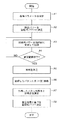
図3に、光照射パワー(記録条件)調整時の動作手順を示す。情報記録再生装置100は、光ディスク114が装填されると、光照射パワーの調整を開始する。システムコントローラ105は、光ヘッド120を、光ディスク114のシステム情報領域に移動する。情報記録再生装置100は、光ディスク114のシステム領域から、Disk Manufacturing informationを読み出し、その情報に基づいて、ディスクの種類、ディスクメーカ名などを取得する。情報記録再生装置100は、取得した媒体の種類やメーカ名などに基づいて、その媒体に関するパラメータテーブルを取得する。システムコントローラ105のパラメータ調整器115は、取得されたパラメータテーブルに基づいて、各種パラメータ(ピークパワー、バイアスパワー、ボトムパワーなど)を設定する(ステップA1)。
FIG. 3 shows an operation procedure when adjusting the light irradiation power (recording condition). When the optical disc 114 is loaded, the information recording / reproducing
パラメータ調整器115は、ステップA1で設定したパワーを、記録時パワー(特定パワー)として選択する(ステップA2)。パラメータ調整器115は、記録時パワーを、ステップA2で設定した記録時パワーから段階的に変化させた複数の条件にて、所定のパタン列を記録する(ステップA3)。パラメータ調整器115は、記録時パワーの変更範囲の全てで記録を行ったか否かを判断する(ステップA4)。パラメータ調整器115は、変更範囲の全てで記録を行っていないと判断したときは、ステップA3に戻り、記録時パワーを変更して、所定パタン列の記録を継続する。
The
ステップA3での記録は、例えば、1ECCブロック単位で行う。パラメータ調整器115は、1ECCブロックごとに記録時パワーを段階的に変化させ、複数の記録時パワーで記録を行う。記録単位は、ECCブロック単位である必要はなく、より小さな単位、例えば、数セクタ単位(HD DVDでは1セクタは26シンクフレーム)であってもよい。パラメータ調整器115は、所定パタン列の記録後、記録パタン列を加熱する際に記録パタン列に対して照射するレーザ光のパワー(加熱量)を決定する(ステップA5)。パラメータ調整器115は、ステップA5で決定したパワーのレーザ光を、ステップA3で記録したパタン列に照射し、記録パタン列を加熱する(ステップA6)。
The recording in step A3 is performed in units of 1 ECC block, for example. The
ステップA6のレーザ光の照射(加熱)は、記録パタンに対して熱負荷を与える目的で行うものである。従って、加熱時のレーザ光のパワーは、マーク形成時に使用されるレーザパワー(ピークパワー)では高すぎる。一方で、パワーが低すぎると、記録パタン列に対して熱負荷が加わらないので、ある程度のパワーは必要である。パラメータ調整器115は、ステップA5では、ステップA1で設定したバイアスパワーを基準に、加熱時に照射するレーザパワーとして決定することができる。これは、バイアスパワーは、マーク形成に影響するパワーではあるものの、それだけでマーク形成が可能なほどパワーが高くないため、熱負荷を与えることができるパワーの基準として適当であると考えられるためである。パラメータ調整器115は、例えば、ステップA1で設定したバイアスパワーを基準に、−30%〜+15%程度のパワーを、加熱時のレーザ照射パワーとして決定する。
The laser beam irradiation (heating) in step A6 is performed for the purpose of applying a thermal load to the recording pattern. Therefore, the power of the laser beam during heating is too high for the laser power (peak power) used during mark formation. On the other hand, if the power is too low, a thermal load is not applied to the recording pattern row, so a certain amount of power is necessary. In step A5, the
パラメータ調整器115は、記録パタン列の加熱後、記録パタン列を再生し、RF回路103から、再生信号品質の測定結果を受け取る(ステップA7)。パラメータ調整器115は、再生信号品質の測定結果に基づいて、光ディスク114に対する情報記録時に光ディスク114に照射するレーザパワーを決定する(ステップA8)。パラメータ調整器115は、例えば、複数のパワーで記録された記録パタン列のそれぞれについて測定された再生信号品質のうちで、再生信号品質が最良となるパワーを、記録時の光照射パワーとして決定する。
The
以下、具体例を交えつつ、本実施形態の動作について説明する。光ディスク114には、HD DVD規格に対応したメディアで、1度だけ記録が可能な追記型メディア(HD DVD−R)を用いる。この光ディスク114は、記録層に有機色素を用い、記録を行うと反射率が高くなるタイプの媒体である。このタイプの媒体は、Low-to-Highメディアと呼ばれる。光ディスク114は、厚さが0.6mmで、直径が12cmの円板状の透明基板(ポリカーボネイト基板)を含む。この透明基板上には、プリグルーブと呼ばれる案内溝が形成されている。 Hereinafter, the operation of the present embodiment will be described with specific examples. As the optical disk 114, a write-once medium (HD DVD-R) that is compatible with the HD DVD standard and can be recorded only once is used. The optical disk 114 is a type of medium that uses an organic dye for the recording layer and has a high reflectance when recording is performed. This type of media is called Low-to-High media. The optical disk 114 includes a disc-shaped transparent substrate (polycarbonate substrate) having a thickness of 0.6 mm and a diameter of 12 cm. Guide grooves called pregrooves are formed on the transparent substrate.
情報記録再生装置100は、情報の記録及び再生時に、レーザ光を案内溝に沿って走査する。情報記録再生装置100は、基板上に成膜された記録層に対してレーザ光を照射し、パタン列を記録する。レーザダイオード121が出射する光の波長は405nmであり、光ヘッド120が有する対物レンズの開口数(NA)は0.65である。光ディスク114の物理フォーマットは、ピットピッチが0.15μmで、トラックピッチが0.40μmのイングルーブ・フォーマットである。また、光ディスク114の記録層にパタン列を記録する際の変復調符号には、ETM(Eight to Twelve Modulation)符号を用いる。情報記録再生装置100におけるパタン列再生時の再生パワーは、0.4mWとする。
The information recording / reproducing
情報記録再生装置100は、マーク形成に際しては、(k−1)型パルストレインの記録ストラテジを用いる。図4に、(k−1)型パルストレインの波形例を示す。図4(a)は、記録するパタンを示し、図4(b)は、図4(a)のパタンを記録する際のレーザ変調波形を示している。図4(b)において、NRZI(Non Return to Zero Inversion)のマーク部に対応する記録ストラテジで、その振幅が最大の上側部分はピークパワーであり、スペース部分に対応する振幅部分はバイアスパワーである。
The information recording / reproducing
(k−1)型パルストレインは、kT(kはマーク長)の長さの記録マークを記録する際に、k−1個のパルスで記録を行うストラテジである。kの値は、変復調方式によって異なる。ここでは、変復調方式をETMとするので、最短マークは2Tであり、kは2以上の自然数となる。(k−1)型パルストレインでは、例えば、2Tマークの記録の際には、k=2に対して、k−1個のパルスを照射するので、記録ストラテジとしての波形は先頭(トップ)パルスのみから成る。3Tマークを記録する際には、2つのパルスを照射するので、記録ストラテジとしての波形は、先頭パルスと最終パルスとから成る。図4(b)に示す波形は、5Tマークの記録に対応しており、中間パルスを含めて4つのパルスを照射している。 The (k-1) type pulse train is a strategy for recording with k-1 pulses when recording a recording mark having a length of kT (k is a mark length). The value of k varies depending on the modulation / demodulation method. Here, since the modulation / demodulation method is ETM, the shortest mark is 2T, and k is a natural number of 2 or more. In the (k-1) type pulse train, for example, when recording a 2T mark, k = 1 pulses are applied to k = 2, so the waveform as a recording strategy is the top (top) pulse. Consist only of. When recording a 3T mark, two pulses are emitted, so that the waveform as a recording strategy consists of a leading pulse and a final pulse. The waveform shown in FIG. 4B corresponds to 5T mark recording, and four pulses including an intermediate pulse are emitted.
情報記録再生装置100に光ディスク114が装填されると、システムコントローラ105は、システム情報領域からDisc Manufacturing informationを読み出し、その情報に基づいてディスクの種類、ディスクメーカ名等を取得する。システムコントローラ105は、取得した情報に基づいて、装填された光ディスク114がHD DVD規格のHD DVD−RのLow-to-High媒体であることを認識する。
When the optical disk 114 is loaded into the information recording / reproducing
パラメータ調整器115は、図3のステップA1で、装填された光ディスク114に対応したパラメータテーブルを読み出し、各種パラメータを設定する。図5に、パラメータテーブル例を示す。このパラメータテーブルの情報は、光ディスク114に記録されている。或いは、装置が各種媒体のパラメータテーブルを記憶しており、読み出したディスク種類やディスクメーカ名などに基づいて、該当するパラメータテーブルを読み出してもよい。
The
パラメータ調整器115は、図5に示すパラメータテーブルに従って、ピークパワーを11.5mWに、バイアスパワーを3.5mWに設定する。ボトムパワーについては、0.1mWに固定することとする。また、パラメータ調整器115は、トップパルス幅や中間パルス幅、最終パルス幅、冷却パルス幅など、パワー以外のパラメータの設定も行う。
The
なお、パワー以外のパラメータについては、媒体から読み出したパラメータを使用せずに、装置にあらかじめ記憶されているパラメータを用いて設定してもよい。パラメータ調整器115は、ステップA1では、上記パラメータ以外にも、以降のステップで記録パワーを段階的に変化させて記録を行う際の変更ステップ数や変更範囲も設定する。パラメータ調整器115は、例えば、変更範囲を、パワーの初期値を0%として±20%、変更ステップを10%に設定する。変更ステップや変更範囲は、媒体のID等に対応させて、装置があらかじめ保持しているものとする。
Note that parameters other than power may be set using parameters stored in advance in the apparatus without using parameters read from the medium. In step A1, the
パラメータ調整器115は、ステップA2で、ステップA1で設定したピークパワー11.5mW、バイアスパワー3.5mWを記録時パワー(特定パワー)として決定する。情報記録再生装置100は、記録時のパワー調整など、各種パラメータの調整には、装置が自由に読み書きできるOPC(Optimum Power Control)可能領域としてドライブテストゾーンを利用する。システムコントローラ105は、光ヘッド120を光ディスク114のドライブテストゾーンに移動し、ステップA3の記録を行う。
In step A2, the
パラメータ調整器115は、ステップA3、ステップA4を繰り返し行い、ピークパワー及びバイアスパワーをそれぞれステップA2で設定したパワーに対して+20%のパワーから10%ずつパワーを段階的に減少させて記録を行う。パラメータ調整器115は、1ECCブロック単位で記録を行い、ECCブロックごとにパワーを変更して記録を行う。0%のピークパワーは11.5mW、バイアスパワーは3.5mWであるので、パラメータ調整器115は、ピークパワーを13.8mW〜9.2mWの範囲、及び、バイアスパワーを4.2mW〜2.8mWの範囲で変化させた組合せで、所定パタン列を記録する。
The
パラメータ調整器115は、ステップA5で、ステップA3で記録時パワーを変化させて記録を行った際のバイアスパワーの中から、加熱の際に記録パタン列に照射するレーザ光のパワーを決定する。パラメータ調整器115は、例えば、0%のバイアスパワーである3.5mWを、加熱時のレーザ照射パワーとして決定する。パラメータ調整器115は、ステップA6で、ステップA3で記録した記録パタン列に対して3.5mWのレーザ光を照射し、複数の記録時パワーで記録したパタン列を、一定の加熱量で加熱する。
In step A5, the
図6に、加熱の様子を示す。図6において、横軸は時間経過を表している。パラメータ調整器115は、レーザ光が、ステップA3で記録された領域の記録トラックに追従する際に、LDドライバ107(図1)に対して、パワーを3.5mWに設定するように指示する。LDドライバ107が3.5mWでLD121を駆動することにより、ステップA3で記録された各領域に対して3.5mWのレーザ光が照射され、レーザ光照射により、熱負荷が与えられる。
FIG. 6 shows the state of heating. In FIG. 6, the horizontal axis represents the passage of time. The
なお、ステップA6では、一定の加熱量で記録パタン列を加熱すればいいので、レーザパワーが一定である必要はまではない。図7に、加熱時のレーザ出力の別例を示す。この例では、図7(a)及び(b)に示すように、レーザパワーの平均が所定のレーザパワー(加熱量)となるように、レーザパワーを変調している。この場合の平均熱量は、鎖線相当となる。一定出力のレーザパワーを用いない場合は、平均熱量が、ステップA5で決定した加熱量相当のパワーとなるように、レーザパワーを制御すればよい。 In step A6, it is only necessary to heat the recording pattern row with a constant heating amount, so it is not necessary that the laser power be constant. FIG. 7 shows another example of laser output during heating. In this example, as shown in FIGS. 7A and 7B, the laser power is modulated so that the average of the laser power becomes a predetermined laser power (heating amount). In this case, the average heat amount is equivalent to a chain line. When laser power with a constant output is not used, the laser power may be controlled so that the average heat amount becomes a power corresponding to the heating amount determined in step A5.
パラメータ調整器115は、ステップA7で、ステップA6で加熱した記録パタン列を再生し、各領域での再生信号品質を測定する。パラメータ調整器115は、ステップA8で、再生信号品質の測定結果に基づいて、情報記録の際に用いるパラメータ(ピークパワーとバイアスパワーとの組)を決定する。図8に、信号品質測定結果を示す。この例では、再生信号品質としてPRSNRを用いている。図8に示す再生信号品質の測定結果では、+10%のパワーの組で、PRSNRが最良となっている。パラメータ調整器115は、ステップA8では、+10%に対応するピークパワー12.7mW、バイアスパワー3.9mWを、情報記録時のパワーとして決定する。
In step A7, the
なお、上記では、ステップA3の記録に用いたピークパワーとバイアスパワーの組み合わせの中から再生信号品質が最良となる組合せを選択することとしたが、再生信号品質測定結果を用いて、所定の再生信号品質が得られる複数のパラメータの中から、情報記録時のパワーの組合せを決定してもよい。複数のパラメータの中から1つのパラメータを選択する方法としては、所定の再生信号品質以上となる測定値に対応する複数のパラメータの平均値又は中央値となるパラメータを選択する方法が考えられる。または、平均値、中央値に最も近いパラメータ値を選択してもよい。パラメータ調整器115は、パラメータの設定精度がある場合などは、再生信号が最良となるパラメータ値を補間などにより算出し、補間により求めたパラメータ値を、情報記録時のパワーとして選択してもよい。
In the above description, the combination with the best reproduction signal quality is selected from the combination of the peak power and the bias power used in the recording in step A3. However, a predetermined reproduction is performed using the reproduction signal quality measurement result. A combination of power at the time of information recording may be determined from a plurality of parameters for obtaining signal quality. As a method of selecting one parameter from a plurality of parameters, a method of selecting a parameter that is an average value or a median value of a plurality of parameters corresponding to a measured value that is equal to or higher than a predetermined reproduction signal quality is conceivable. Alternatively, the parameter value closest to the average value and the median value may be selected. The
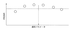
図9に、複数のパラメータから情報記録時のパワーを決定する例を示す。パラメータ調整器115は、まず、再生信号品質が所定の性能以上となるパラメータの範囲を求める。ここでは、PRSNRが20以上となるパラメータの範囲を求めることとする。図9では、所定の性能以上となるパラメータは4つある。パラメータ調整器115は、その4つのパラメータの平均値を求め、その値を、情報記録時のパワーとして決定する。このようにすることで、PRSNR20以上となるパラメータのうち、真ん中の2つの間に対応するパラメータを、情報記録時のパワーとして決定できる。
FIG. 9 shows an example of determining the power at the time of recording information from a plurality of parameters. The
図10に、環境加速試験後の再生信号品質の測定結果を示す。図8との比較を容易にするために、同一ディスクに対し、ピークパワー及びバイアスパワーをそれぞれ11.5mW、3.5mWを0%として、±20%の範囲で10%ステップで変化させて記録を行った。その後、環境加速試験として、温度80℃、60%RH(相対湿度)の加速環境下で500時間保存後に、記録した領域を再生しPRSNRを測定した。 FIG. 10 shows the measurement result of the reproduction signal quality after the environmental acceleration test. In order to make comparison with FIG. 8 easier, recording is performed on the same disk by changing the peak power and the bias power by 11.5 mW and 3.5 mW at 0% in 10% steps within a range of ± 20%. Went. Thereafter, as an environmental acceleration test, the recorded region was reproduced and PRSNR was measured after storage for 500 hours in an accelerated environment at a temperature of 80 ° C. and 60% RH (relative humidity).
図11に、環境加速試験の前のPRSNR測定結果を示す。図10と同様な条件で、環境加速試験前に記録した領域を再生し、PRSNRを測定すると、図11に示す測定結果が得られる。環境加速試験前後でPRSNRを比較すると、環境加速試験前では0%でPRSNRが最良となるのに対し、環境加速試験後では+10%でPRSNRが最良となっている。このことは、保存性を上げるためには、記録直後にPRSNRが最良となる0%のパワーよりも、+10%のパワーで記録した方がよいということを示している。 FIG. 11 shows the PRSNR measurement results before the environmental acceleration test. When the area recorded before the environmental acceleration test is reproduced under the same conditions as in FIG. 10 and the PRSNR is measured, the measurement results shown in FIG. 11 are obtained. When comparing the PRSNR before and after the environmental acceleration test, the PRSNR is the best at 0% before the environmental acceleration test, whereas the PRSNR is the best at + 10% after the environmental acceleration test. This indicates that in order to improve the storage stability, it is better to record at + 10% power than 0% power at which the PRSNR is optimal immediately after recording.
図8と図10とを比較すると、図8でPRSNRが最良となるパラメータは、図10で環境加速試験後にPRSNRが最良となるパラメータと一致している。これは、記録パタン列を加熱するステップ(ステップA6)を追加し、記録パタンに対して熱負荷を与えた後に再生信号品質を測定して記録時パワーを決定することで、環境加速試験を行わなくても、保存安定性が高い記録条件を記録時パワーとして決定できるということを示している。 Comparing FIG. 8 with FIG. 10, the parameter with the best PRSNR in FIG. 8 matches the parameter with the best PRSNR after the environmental acceleration test in FIG. This is done by adding an additional step (step A6) of heating the recording pattern row, measuring the reproduction signal quality after applying a thermal load to the recording pattern, and determining the recording power, thereby performing an environmental acceleration test. This shows that a recording condition with high storage stability can be determined as the recording power even if not.
本実施形態では、光ディスク114に記録した記録パタン列を加熱し、加熱後に記録パタン列を再生して再生信号品質を求める。記録パタン列を加熱し、記録パタン列に対して熱負荷を与えることで、環境加速試験を行なわなくても、環境加速試験後の記録パタン列の状態を作り出すことができる。この記録パタン列を再生し、再生信号品質を測定して記録時パワーを決定することで、情報記録再生装置単体で、長時間使用後の状態でPRSNRが確保できる記録時パワーを求めることができる。つまり、長期にわたり、記録されたデータの消失を防止できる記録時パワー条件を求めることができる。本実施形態では、環境加速試験を必要とせず、また、情報記録再生装置単体でアーカイバル特性が確保しやすい記録条件を得ることができるので、簡易、かつ、短時間で、アーカイバル特性が確保できる記録条件を設定することができる。 In the present embodiment, the recording pattern row recorded on the optical disc 114 is heated, and the recording pattern row is reproduced after heating to obtain the reproduction signal quality. By heating the recording pattern row and applying a thermal load to the recording pattern row, the state of the recording pattern row after the environmental acceleration test can be created without performing the environmental acceleration test. By reproducing the recording pattern sequence and measuring the reproduction signal quality to determine the recording power, it is possible to obtain the recording power that can ensure the PRSNR in a state after long-time use by the information recording / reproducing apparatus alone. . That is, it is possible to obtain a recording power condition that can prevent the loss of recorded data over a long period of time. In this embodiment, an environmental acceleration test is not required, and recording conditions that can easily ensure archival characteristics with a single information recording / reproducing apparatus can be obtained, so that archival characteristics can be ensured easily and in a short time. Possible recording conditions can be set.
次に、本発明の第2実施形態について説明する。第2実施形態における情報記録再生装置の構成は、図1に示す第1実施形態の情報記録再生装置100の構成と同様である。全体的な処理の流れは、図3に示す手順と同様である。第1実施形態では、図3のステップA5にて、バイアスパワーを基準として加熱時の光照射パワーを決定した。しかし、光ディスク114によっては、ステップA1で設定するパワーの初期値が必ずしもその媒体に適したパワーとなっていない場合もある。その場合にバイアスパワーを基準として加熱時のパワーを決定すると、加熱量が適切とならないことが考えられる。本実施形態では、加熱量決定に先立って、所定のパタン列を記録し、記録パタン列を加熱し、加熱したパタン列の再生信号品質を測定して、加熱量を決定する。
Next, a second embodiment of the present invention will be described. The configuration of the information recording / reproducing apparatus in the second embodiment is the same as that of the information recording / reproducing
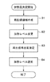
図12に、加熱量決定の動作手順を示す。この処理は、図3のステップA5の処理に相当する。加熱量の決定では、パラメータ調整器115は、まず、ステップA2(図3)で設定された特定パワーを記録時パワーとして、複数範囲にわたりパタン列を記録する(ステップB1)。次いで、パラメータ調整器115は、加熱量を変化させながら、ステップB1で複数領域に記録した記録パタン列を加熱する(ステップB2)。パラメータ調整器115は、LDドライバ107(図1)を制御し、領域ごとに記録パタン列に照射するレーザ光の照射パワーを変化させ、領域ごとに異なる加熱量で記録パタン列を加熱する。
FIG. 12 shows an operation procedure for determining the heating amount. This process corresponds to the process of step A5 in FIG. In determining the heating amount, the
パラメータ調整器115は、ステップB1では、ステップB2で加熱量を変化させる際の変化量、及び、変化ステップ幅に応じた数の領域に、所定のパタン列を記録する。例えば、加熱量の変化範囲がステップA2で決定されたバイアスパワーに対して±1.0mWの範囲であり、変化ステップが0.5mWであるときは、加熱量を5通り変化させることになるので、5つの領域に、所定の記録パタン列を記録する。記録する領域の単位は、例えばECCブロック単位とする。これら記録された領域は、同程度の性能を有する領域である。
In step B1, the
パラメータ調整器115は、ステップB2で加熱された記録パタン列を再生し、領域ごと、つまりは加熱量ごとに、再生信号品質を測定する(ステップB3)。パラメータ調整器115は、ステップB3で測定された領域ごとの再生信号品質に基づいて、記録パタン列を加熱する際の加熱量を決定する(ステップB4)。その後、パラメータ調整器115は、図3のステップA6で、ステップB4で決定したパワーのレーザ光をステップA3で記録した記録パタン列に照射し、記録パタン列を一定の加熱量で加熱する。
The
パラメータ調整器115は、例えば再生信号品質としてPRSNRを用いる場合は、ステップB4で、PRSNRが特定レベル付近となる領域に対応する加熱量を、ステップA6での加熱量として決定する。このときのPRSNRの特定レベルは、性能境界として一般に用いられるPRSNR15以下が好ましい。また、光学情報記録再生装置では、経験的に、PRSNRが8を下回ると安定的にPLLがかからなくなるので、特定レベルの下限は8程度が好ましい。再生信号品質としてPRSNR以外を用いる場合は、PRSNR8〜15に対応するエラーレート又はエラーバイト数に相当する値を用いればよい。
For example, when PRSNR is used as the reproduction signal quality, the
以下、具体例を用いつつ、本実施形態の動作について説明する。光ディスク114には、第1実施形態で用いた媒体とは異なるメーカSの媒体を用いる。この光ディスク114には、パラメータテーブルに相当する情報は記録されておらず、ステップA1では、装置があらかじめ保持している情報を用いて、パラメータ設定を行う。このとき設定するピークパワーは11.0mWで、バイアスパワーは3.0mWとする。 Hereinafter, the operation of the present embodiment will be described using a specific example. For the optical disc 114, a medium of manufacturer S different from the medium used in the first embodiment is used. Information corresponding to the parameter table is not recorded on the optical disc 114, and parameter setting is performed using information previously held by the apparatus in step A1. The peak power set at this time is 11.0 mW, and the bias power is 3.0 mW.
パラメータ調整器115は、ステップB1で、5ECCブロックに所定パタン列を記録する。その後、パラメータ調整器115は、ステップB2で、記録した5ECCブロックに対し、ECCブロックごとに加熱量を変更しつつ、記録パタン列を加熱する。その後、パラメータ調整器115は、ステップB3で、ステップB1で記録したパタン列を再生し、ECCブロックごとに、再生信号品質を測定する。
In step B1, the
図13(a)に、ステップB2の加熱時のレーザパワーの変化の様子を示す。パラメータ調整器115は、レーザパワーをバイアスパワー3.0mWを中心とした2.0mWから4.0mWまでの範囲で、ECCブロックごとにレーザパワー(加熱量)を0.5mWステップで変更しつつ、各ECCブロックに記録したパタン列に対してレーザ光を照射する。図13(b)に、再生信号品質の測定結果を示す。図13(b)において、横軸は加熱量を表している。ここでは、再生信号品質にPRSNRを用いている。PRSNRは、2.0mWで加熱した領域が最良となり、4.0mWで加熱した領域が最も悪くなる。
FIG. 13A shows how the laser power changes during heating in step B2. The
図13(b)に示す鎖線Aは、特定レベル以下の品質を示している。図13(b)では、この特定レベルを、PRSNR=10としている。パラメータ調整器115は、ステップB4で、測定されたPRSNRが、鎖線A付近となる領域の加熱量を、ステップA6で記録パタン列を加熱する際の加熱量として決定する。図13(b)では、PRSNRの測定結果が鎖線Aを横切る前後のうちで、加熱量2.5mWに対応する領域のPRSNRが、PRSNR=10に最も近い。パラメータ調整器115は、この加熱量2.5mWを、ステップA6での加熱量として決定する。
A chain line A shown in FIG. 13B indicates quality below a specific level. In FIG. 13B, this specific level is PRSNR = 10. In step B4, the
なお、加熱量の決定は上記には限定されず、PRSNRが鎖線Aを最初に下回る領域の加熱量を、ステップA6での加熱量として決定してもよい。また、PRSNRが鎖線Aを下回る直前の加熱量をステップA6での加熱量として決定してもよい。或いは、PRSNRが鎖線Aをまたぐ前後の加熱量から、PRSNRが鎖線Aと一致する加熱量を算術的に求め、その加熱量をステップA6での加熱量として決定してもよい。 The determination of the heating amount is not limited to the above, and the heating amount in the region where the PRSNR first falls below the chain line A may be determined as the heating amount in step A6. Further, the heating amount immediately before PRSNR falls below the chain line A may be determined as the heating amount in step A6. Alternatively, the heating amount at which the PRSNR matches the chain line A may be obtained arithmetically from the heating amount before and after the PRSNR crosses the chain line A, and the heating amount may be determined as the heating amount in step A6.
本実施形態では、記録した領域を再生した際の再生信号品質に基づいて、記録時パワー調整の際に記録パタン列を加熱する際の加熱量を決定する。このようにすることで、加熱量を、実際の装置と媒体との組み合わせに応じて決定することができ、適合性を上げることができる。その結果として、記録時パワー調整を高精度で行うことができると共に、特定の装置と媒体との組み合わせに依存しない汎用性を高めた運用が可能となる。特に、装置が出荷された時点では市場に存在していない媒体や、使用することを想定しない未知ディスク媒体、或いは、装置があらかじめ保持している情報に対応しない場合などでは、ステップA6で、どのレベルの加熱量で加熱してよいかが不明となる。本実施形態では、そのような場合でも、適切な加熱量で、記録パタン列を加熱できる。 In the present embodiment, based on the reproduction signal quality when the recorded area is reproduced, the heating amount for heating the recording pattern row is determined during the power adjustment during recording. By doing in this way, a heating amount can be determined according to the combination of an actual apparatus and a medium, and adaptability can be raised. As a result, power adjustment during recording can be performed with high accuracy, and operation with improved versatility that does not depend on a combination of a specific apparatus and medium can be performed. In particular, in the case of a medium that does not exist on the market at the time of shipment of the device, an unknown disk medium that is not supposed to be used, or a case that does not correspond to information held in advance by the device, in step A6, which It is unclear whether it is possible to heat at the heating level. In this embodiment, even in such a case, the recording pattern row can be heated with an appropriate heating amount.
ここで、図14(a)〜(e)に、加熱量を変化させたときのPRSNRの測定結果例を示す。図14に示すPRSNRの測定結果は、図3のステップA7で測定されるPRSNRに相当する。図14において、横軸は記録時パワー条件を表している。図14(a)〜(e)において、鎖線Aは、図13(b)と同様の特定レベルを表している。鎖線Aのレベルは、PRSNR=10のレベルである。 Here, FIGS. 14A to 14E show measurement result examples of the PRSNR when the heating amount is changed. The PRSNR measurement result shown in FIG. 14 corresponds to the PRSNR measured in step A7 in FIG. In FIG. 14, the horizontal axis represents the recording power condition. 14A to 14E, a chain line A represents a specific level similar to that in FIG. 13B. The level of the chain line A is a level of PRSNR = 10.
図14(a)は、加熱量0、つまり、ステップA5の加熱を行わずに、異なる記録時パワーで記録された記録パタン列を再生した際のPRSNR(○)を示している。図14(b)〜図14(e)は、図14(a)と同一の記録パタン列に対して、ステップA5で加熱を行った後のPRSNRの測定結果(□)を示している。加熱量は、図14(b)から図14(e)に向けて大きくなっている。 FIG. 14A shows a PRSNR (◯) when a heating pattern is reproduced, that is, a recording pattern sequence recorded at a different recording power without heating in step A5. FIGS. 14B to 14E show the measurement results (□) of the PRSNR after heating the same pattern pattern as in FIG. 14A in step A5. The amount of heating increases from FIG. 14 (b) to FIG. 14 (e).
図14(a)〜(e)を参照すると、記録直後の状態(図14(a))に対して加熱量を増加させつつ熱を加えていった場合、必ずしも、記録直後で性能がよい記録条件が、熱負荷に対し強い記録条件でないことがわかる。また、図14(b)のように、加熱量が小さく、記録パタン列に与える熱負荷が少なすぎる場合は、性能劣化はほとんど発生せず、図14(a)と同様なPRSNRが得られることになることがわかる。従って、この加熱量では、熱負荷に対して強い記録条件を得ることはできない。逆に、図14(e)のように、加熱量が大きく、記録パタン列に与える熱負荷が多すぎる場合は、性能劣化が激しすぎて、記録パタン列が破壊される結果となることわかる。従って、この加熱量でも、熱負荷に対して強い記録条件を得ることはできない。 Referring to FIGS. 14A to 14E, when heat is applied while increasing the heating amount with respect to the state immediately after recording (FIG. 14A), the recording is always good immediately after recording. It can be seen that the conditions are not recording conditions that are strong against heat load. Further, as shown in FIG. 14B, when the heating amount is small and the thermal load applied to the recording pattern row is too small, performance degradation hardly occurs, and the same PRSNR as in FIG. 14A can be obtained. It turns out that it becomes. Therefore, with this heating amount, it is not possible to obtain recording conditions that are strong against the heat load. On the contrary, as shown in FIG. 14E, when the heating amount is large and the thermal load applied to the recording pattern row is too large, the performance deterioration is so severe that the recording pattern row is destroyed. . Therefore, even with this heating amount, it is not possible to obtain recording conditions that are strong against the heat load.
図14(c)及び(d)は、各記録条件に対してPRSNRの絶対値は異なるものの、各条件に対する相対的な関係は同じである。すなわち、PRSNRが最良となる記録条件は同じである。従って、ステップB4にて、これらに対応する加熱量を、ステップA6での加熱量として決定することで、熱負荷に対して強い記録条件を得ることができる。言い換えれば、図12に示す手順で、加熱量を決定することで、所望の記録時パワー選定を適切に行うことができる加熱量を決定でき、その加熱量を用いて加熱することで、適合性を上げ、選択精度の確保を図ることができる。また、特定の装置と媒体との組み合わせに依存せずに加熱量を決定できるので、汎用性を高めることができるという効果も得られる。 14C and 14D, the absolute value of PRSNR is different for each recording condition, but the relative relationship for each condition is the same. That is, the recording conditions that give the best PRSNR are the same. Therefore, by determining the heating amount corresponding to these in step B4 as the heating amount in step A6, it is possible to obtain a recording condition strong against the heat load. In other words, by determining the heating amount according to the procedure shown in FIG. 12, it is possible to determine the heating amount at which a desired recording power can be appropriately selected. The selection accuracy can be ensured. In addition, since the heating amount can be determined without depending on the combination of a specific device and medium, an effect that versatility can be improved is also obtained.
なお、ステップB4では、図14(c)に対応する加熱量と図14(d)に対応する加熱量のように、複数の加熱量が選択可能となる場合がある。その場合、何れも用いたとしても、その後の処理に影響はない。複数の候補がある場合に、その候補から何れを選ぶかは、装置内の処理に依存する。装置に、自律的に判断して選択するアルゴリズムを実装するという手法も考えられるが、設計段階で適宜何れが選ばれるかを決めておくことが好ましい。 In step B4, a plurality of heating amounts may be selectable, such as the heating amount corresponding to FIG. 14C and the heating amount corresponding to FIG. In that case, even if either is used, there is no influence on the subsequent processing. When there are a plurality of candidates, which one to select from the candidates depends on the processing in the apparatus. Although a method of mounting an algorithm that makes an autonomous determination and selection in the apparatus is conceivable, it is preferable to determine which one is appropriately selected at the design stage.
ところで、ピークパワーとバイアスパワーとの双方が形成マークの品質に影響を与えるような媒体では、バイアスパワーはマーク形成に影響するパワーである。特に、波長405nm近傍のレーザ光に対応した追記型の媒体では、この傾向は顕著である。このような媒体では、バイアスパワーは熱的に影響があるパワーなので、ステップA6で記録パタン列に与える熱負荷の目安になり得る。図14では、図14(c)の加熱量をバイアスパワー相当とすると、図14(d)の加熱量はバイアスパワーよりも少し高いパワーでの加熱量となる。また、図14(d)の加熱量をバイアスパワー相当とすると、図14(c)の加熱量は、バイアスパワーよりも少し低いパワーでの加熱量となる。 By the way, in a medium in which both peak power and bias power affect the quality of the formed mark, the bias power is power that affects mark formation. This tendency is particularly remarkable in a write-once medium corresponding to laser light having a wavelength of around 405 nm. In such a medium, since the bias power is a power that has a thermal influence, it can be a measure of the thermal load applied to the recording pattern array in step A6. In FIG. 14, if the heating amount in FIG. 14C is equivalent to the bias power, the heating amount in FIG. 14D is a heating amount at a slightly higher power than the bias power. Further, if the heating amount in FIG. 14D is equivalent to the bias power, the heating amount in FIG. 14C is a heating amount with a power slightly lower than the bias power.
図12に示す手順で加熱量を決定する際には、バイアスパワーを目安に、その近傍から、ステップA6での加熱量として用いるパワーを決定すればよい。このような目安があることは、最適解を見つける上で、大変重要である。すなわち、バイアスパワーの近傍に決定すべき加熱量があることがわかっているので、その周辺で決定すべき加熱量を探せばよい。加熱量を探す範囲が限られていることで、闇雲に加熱量を変化させて加熱量を決定するのに比べて、高速、かつ、正確に、適切な加熱量を決定することができる。 When the heating amount is determined by the procedure shown in FIG. 12, the power used as the heating amount in step A6 may be determined from the vicinity of the bias power as a guide. Having such a guide is very important in finding the optimal solution. That is, since it is known that there is a heating amount to be determined in the vicinity of the bias power, a heating amount to be determined around the bias power may be searched. Since the range for searching for the heating amount is limited, an appropriate heating amount can be determined at high speed and more accurately than when the heating amount is determined by changing the heating amount to dark clouds.
引き続き、本発明の第3実施形態について説明する。第3実施形態における情報記録再生装置の構成は、図1に示す第1実施形態の情報記録再生装置100の構成と同様である。全体的な処理の流れは、図3に示す手順と同様である。第1実施形態では、図3のステップA2で、ステップA1で設定したパワーを記録時パワー(特定パワー)として選択した。しかし、光ディスク114によっては、ステップA2で設定した記録時パワーにて所望の再生信号品質が得られない場合もある。本実施形態では、ステップA2で記録時パワーを決定する際に、光ディスク114に対する記録を行い、それを再生して所望の再生信号品質が得られることを確認する。
Subsequently, a third embodiment of the present invention will be described. The configuration of the information recording / reproducing apparatus in the third embodiment is the same as that of the information recording / reproducing
図15に、記録時パワー設定時の手順を示す。この処理は、図3のステップA2の処理に相当する。パラメータ調整器115は、ステップA1で各種パラメータを設定すると、ステップA1で設定した記録時パワーにて記録を行い(ステップC1)、記録した領域を再生して再生信号品質を測定する(ステップC2)。
FIG. 15 shows the procedure when recording power is set. This process corresponds to the process of step A2 in FIG. When the
パラメータ調整器115は、測定された再生信号品質と、所望の再生信号品質とを比較し、再生性能が担保されているかの判定を行う(ステップC3)。つまり、実際に記録を行って測定された再生信号品質が、想定される性能に見合うか否かをチェックする。所望の再生信号品質は、媒体ごとに用意され、情報記録再生装置内にあらかじめ記憶されている。パラメータ調整器115は、ステップC3で再生性能が担保されていると判定すると、ステップA1で設定したパワーを、記録時パワーに設定する(ステップC4)。
The
パラメータ調整器115は、ステップC3で再生性能が担保されていないと判定すると、記録時パワーを変化させ、複数の記録時パワーにて記録を行う(ステップC5)。パラメータ調整器115は、ステップC5では、例えば、バイアスパワーをステップA1で設定したパワーに固定し、ピークパワーをステップA1で設定したパワーから所定の範囲で変化させたパワーの記録時パワーで、複数の領域に所定の記録パタンを記録する。或いは、ピークパワーとバイアスパワーとを変化させた複数の組み合わせの記録時パワーで、所定の記録パタンを記録してもよい。
If the
パラメータ調整器115は、ステップC5で記録した領域を再生し、再生信号品質を測定する(ステップC6)。パラメータ調整器115は、再生信号品質測定結果に基づいて、記録時パワーとして用いるパワーを選択し、そのパワーを記録時パワーに設定する(ステップC7)。パラメータ調整器115は、ステップC7では、例えば最良の再生信号品質が得られる領域の記録に用いた記録時パワーを、記録時パワーに設定する。
The
ステップC4又はステップC7で設定したパワーは、ステップA3で記録時パワーを段階的に変化させて記録を行う際の基準のパワーとして使用される。例えば、記録時パワーを、基準となるパワーに対して±10%の範囲で変化させてステップA3の記録を行う場合には、ステップC4又はステップC7で設定したパワーが、基準のパワー(0%のパワー)として用いられる。 The power set in step C4 or step C7 is used as a reference power when recording is performed by stepwise changing the recording power in step A3. For example, when the recording power is changed in a range of ± 10% with respect to the reference power and the recording in step A3 is performed, the power set in step C4 or step C7 is the reference power (0%). Power).
以下、具体例を用いつつ、本実施形態の動作について説明する。以下では、光ディスク114として、媒体メーカMの媒体と、媒体メーカNの媒体との2つを考える。図16に、パラメータテーブルを示す。この情報は、装置内にあらかじめ記憶されている。はじめに、媒体メーカMの媒体が装填されたとする。情報記録再生装置100は、光ディスク114が装填されると、図16に示すパラメータテーブルから、装填された光ディスク114(媒体メーカM)に対応した情報を取得する。パラメータ調整器115は、ステップA1(図3)で、取得された情報により各種パラメータの設定を行う。
Hereinafter, the operation of the present embodiment will be described using a specific example. Hereinafter, two media, that is, the medium of the medium manufacturer M and the medium of the medium manufacturer N are considered as the optical disk 114. FIG. 16 shows a parameter table. This information is stored in advance in the apparatus. First, it is assumed that the medium of the medium manufacturer M is loaded. When the optical disc 114 is loaded, the information recording / reproducing
パラメータ調整器115は、ステップC1で、所定の記録可能領域に、ステップA1で設定されたパワーを用いて記録を行う。図16を参照すると、媒体メーカMの媒体に対するピークパワーは11.0mWで、バイアスパワーは3.0mWであるので、ステップC1では、これらの組み合わせのパワーを記録時パワーとして記録を行う。記録は、例えばECCブロック単位で行い、4ブロック分の領域に対して記録を行う。パラメータ調整器115は、ステップC2で、ステップC1で記録した領域を再生し、再生信号品質を測定する。再生信号品質には、PRSNRを用いる。
In step C1, the
パラメータ調整器115は、ステップC3で、ステップC2で測定した再生信号品質と、所望の再生性能とを比較する。図16に示すパラメータテーブルを参照すると、媒体メーカMの媒体に対しては、想定PRSNRとして、PRSNR=20が記憶されている。ステップC2で測定された再生信号品質(4ECCブロックの平均値)がPRSNR=20.5であるとすると、このPRSNRは想定PRSNRよりも高い。従って、パラメータ調整器115は、ステップC3で、再生性能が担保されていると判定する。
In step C3, the
パラメータ調整器115は、ステップC4で、ステップC1での記録に用いたピークパワー11.0mW、バイアスパワー3.0mWの組を、記録時パワーとして設定する。以降、パラメータ調整器115は、ステップA3(図3)で、記録時パワーを変更しつつ記録を行う際には、ステップC4で設定したピークパワー11.0mW、バイアスパワー3.0mWを中心に、記録時パワーを段階的に変化させる。また、パラメータ調整器115は、ステップA5では、ステップC4で設定したバイアスパワー3.0mWを基準に、加熱量を決定する。
In step C4, the
次に、媒体メーカNの媒体が装填されたとする。情報記録再生装置100は、光ディスク114が装填されると、図16に示すパラメータテーブルから、装填された光ディスク114(媒体メーカN)に対応した情報を取得する。パラメータ調整器115は、ステップA1(図3)で、取得された情報により各種パラメータの設定を行う。
Next, it is assumed that the medium of the medium manufacturer N is loaded. When the optical disc 114 is loaded, the information recording / reproducing
パラメータ調整器115は、ステップC1で、所定の記録可能領域に、ステップA1で設定されたパワーを用いて記録を行う。図16を参照すると、媒体メーカNの媒体に対するピークパワーは12.0mWで、バイアスパワーは3.4mWであるので、ステップC1では、これらの組み合わせのパワーを記録時パワーとして記録を行う。パラメータ調整器115は、ステップC2で、ステップC1で記録した領域を再生し、再生信号品質を測定する。
In step C1, the
パラメータ調整器115は、ステップC3で、ステップC2で測定した再生信号品質と、所望の再生性能とを比較する。図16に示すパラメータテーブルを参照すると、媒体メーカNの媒体に対しては、想定PRSNRとして、PRSNR=20が記憶されている。ステップC2で測定された再生信号品質(平均)がPRSNR=18.5であるとすると、このPRSNRは想定PRSNRよりも低い。従って、パラメータ調整器115は、ステップC3で、再生性能が担保されていないと判定する。
In step C3, the
パラメータ調整器115は、ステップC3で再生性能が担保されていないと判定すると、ステップC5に移行し、ドライブテストゾーンに対し、記録条件を変化させつつ、所定パタンを記録する。パラメータ調整器115は、ステップC5では、例えば、バイアスパワーを3.4mWとして、ピークパワーを12.0mWから±20%の範囲で、ECCブロックごとに5%ステップで変化させて記録を行う。パラメータ調整器115は、ステップC6で、ステップC5で記録した領域を再生し、記録条件ごとに、再生信号品質を算出する。
If the
パラメータ調整器115は、ステップC7で、再生信号品質の測定結果に基づいて、記録時パワーを決定する。図17に、PRSNRの測定結果を示す。この例では、PRSNRは、ピークパワー+5%(12.6mW)のときに最良となる。パラメータ調整器115は、ステップC7では、このピークパワー12.6mWと、バイアスパワー3.4mWとの組を、記録時パワーとして決定する。なお、このとき、測定された再生信号品質が最良となる条件にて、必ずしも、ステップC3で比較した所望の再生性能を超えている必要はない。
In step C7, the
以降、パラメータ調整器115は、ステップA3(図3)で、記録時パワーを変更しつつ記録を行う際には、ステップC7で設定したピークパワー12.6mW、バイアスパワー3.4mWを中心に、記録時パワーを段階的に変化させる。また、パラメータ調整器115は、ステップA5では、ステップC7で設定したバイアスパワー3.4mWを基準に、加熱量を決定する。
Thereafter, when the
本実施形態では、記録時パワーの調整に先立って、記録時パワーの調整時の記録時パワーにて、所望の再生性能が得られるか否かを判断する。所望の再生性能が得られないときは、光ディスク114に対して記録を行い、よりよい再生性能が得られる記録条件を探す。このようにすることで、再生性能が低い記録時パワーにて記録時パワーの調整を行うことを避けることができ、記録時パワーの調整精度を向上することができる。 In the present embodiment, prior to the adjustment of the recording power, it is determined whether or not a desired reproduction performance can be obtained with the recording power when the recording power is adjusted. When the desired reproduction performance cannot be obtained, recording is performed on the optical disc 114 to search for a recording condition for obtaining better reproduction performance. By doing in this way, it is possible to avoid adjusting the recording power with the recording power with low reproduction performance, and it is possible to improve the adjustment accuracy of the recording power.
記録時パワーの調整に先立って、記録時パワーの調整時の記録時パワーにて、所望の再生性能が得られることを確認する理由は、装置と媒体との組み合わせによっては、必ずしも想定した装置状態や媒体特性とはならない場合があるためである。このような場合、性能が保証されていないパタン列を用いることになる。性能が保証されていないパタン列に対して熱負荷を与え、記録時パワー調整を行っても、必ずしも正確に保存安定性が高いパワーを選べるとは限らない。異常な結果となることや、局所最適な結果となることが考えられる。また、汎用性も損なわれることになる。本実施形態では、はじめに所期の性能が得られるか否かを判定し、所期の性能が得られないときは、できるだけ高い性能が得られる記録条件を探すことで、その後の処理の精度を確保することができる。また、特定の装置と媒体との組み合わせに依存せず、汎用性を高めることができる。 Before adjusting the recording power, the reason for confirming that the desired playback performance can be obtained with the recording power when adjusting the recording power is that depending on the combination of the device and the medium, the assumed device status This is because the medium characteristics may not be obtained. In such a case, a pattern string whose performance is not guaranteed is used. Even if a thermal load is applied to a pattern row for which performance is not guaranteed and power adjustment is performed during recording, it is not always possible to select power with high storage stability accurately. It may be an abnormal result or a locally optimal result. Moreover, versatility will also be impaired. In this embodiment, it is first determined whether or not the expected performance can be obtained, and when the expected performance is not obtained, the accuracy of the subsequent processing is improved by searching for a recording condition that provides the highest possible performance. Can be secured. Further, versatility can be improved without depending on a combination of a specific device and a medium.
なお、上記各実施形態では、ステップA3(図3)、ステップC1(図15)で記録を行う際に、記録時パワーを一定の変化幅(ステップ幅)で変化させたが、変化幅は一定である必要はない。また、ステップB2(図12)で加熱量を変化させる際の変化幅についても、一定の変化幅である必要はなく、変化のさせ方は任意である。具体的には、ピークパワーとバイアスパワーとを、それぞれ12.0mW、3.0mWから±25%の範囲で変化させる際に、+25、+20、+15、+10、0、−10、−15、−20、−25(%)と変化させてもよい。この例では、0%〜±10%の範囲ではステップ幅を10%とし、10%〜25%ではステップ幅を5%としている。 In each of the above embodiments, when recording is performed in step A3 (FIG. 3) and step C1 (FIG. 15), the recording power is changed with a constant change width (step width), but the change width is constant. Need not be. Further, the change width when changing the heating amount in step B2 (FIG. 12) does not need to be a constant change width, and the change is arbitrary. Specifically, when changing the peak power and the bias power in the range of ± 2.0% from 12.0 mW and 3.0 mW, respectively, +25, +20, +15, +10, 0, −10, −15, − It may be changed to 20, -25 (%). In this example, the step width is 10% in the range of 0% to ± 10%, and the step width is 5% in the range of 10% to 25%.
図18に、記録時パワーを上記のように変化させてPRSNRを測定した結果を示す。図18を参照すると、記録時パワー0%(12.0mW、3.0mW)付近では、記録時パワー変化に対するPRSNRの変化が小さいことがわかる。また、記録時パワー0%を離れるほど、記録時パワー変化に対するPRSNR変化が大きいことがわかる。変化が小さい0%付近のステップ幅を大きめに設定し、変化が大きい周辺部分のステップ幅を小さく設定することで、特性変化が小さい部分の特性を粗めに調べ、特性変化が大きい部分の特性を詳細に調べることができる。これにより、処理の高速化、余分な領域の消費を抑えることが可能である。 FIG. 18 shows the result of measuring the PRSNR while changing the recording power as described above. Referring to FIG. 18, it can be seen that the PRSNR change with respect to the recording power change is small in the vicinity of the recording power of 0% (12.0 mW, 3.0 mW). It can also be seen that the PRSNR change with respect to the recording power change increases as the recording power becomes 0%. By setting a large step width near 0% where the change is small and setting a small step width in the peripheral part where the change is large, the characteristics of the portion where the characteristic change is small are roughly investigated, and the characteristic of the portion where the characteristic change is large Can be examined in detail. As a result, the processing speed can be increased and the consumption of extra areas can be suppressed.
上記各実施形態では、記録時パワー調整(図3)や加熱量決定(図12)、特定パワーの決定(図15)にて、所定のパタン列を記録し、既記録領域を作成して再生信号品質を利用した。しかし、光ディスク114のドライブテストゾーン内の領域などに、調整に使用してよいパタン列(品質が保証されたパタン列)が既に存在している場合には、そのパタン列を使用して、記録時パワー調整、加熱量決定、特定パワーの決定を行ってもよい。既に存在するパタン列を使用することで、記録動作処理を減らすことができ、処理の高速化、調整領域の節約が可能となる。 In each of the above-described embodiments, a predetermined pattern sequence is recorded in the power adjustment during recording (FIG. 3), the heating amount determination (FIG. 12), and the specific power determination (FIG. 15), and a recorded area is created and reproduced. Utilized signal quality. However, if there is already a pattern row (pattern row with guaranteed quality) that can be used for adjustment in an area in the drive test zone of the optical disk 114, the pattern row is used to record. Time power adjustment, heating amount determination, and specific power determination may be performed. By using an already existing pattern sequence, it is possible to reduce the recording operation processing, speed up the processing, and save the adjustment area.
上記、既に存在するパタン列を使用する場合には、ドライブテストゾーン内の領域に、調整に使用可能なパタン列が存在するか否かを判定し、存在する場合に、そのパタン列を使用するとすればよい。また、その判定後、そのパタン列が所定のレベル品質を満たすか否か調べ、所定のレベル品質を満たすと判定したときに、そのパタン列を用いて調整を実施するとすればよい。調整に使用可能なパタン列が存在しない、或いは、パタン列は存在するがその品質が低いときには、新たに記録を行い、記録したパタン列を用いて調整を行えばよい。 When using a pattern string that already exists, determine whether there is a pattern string that can be used for adjustment in the area within the drive test zone, and if it exists, use that pattern string do it. Further, after the determination, whether or not the pattern sequence satisfies a predetermined level quality is checked, and when it is determined that the predetermined level quality is satisfied, the adjustment may be performed using the pattern sequence. When there is no pattern row that can be used for adjustment, or there is a pattern row but its quality is low, new recording is performed and adjustment is performed using the recorded pattern row.
上記各実施形態では、レーザ波長405nm、対物レンズの開口数0.65を用いたが、これには限定されず、上記各実施形態の記録時パワー調整は、種々のレーザ波長、開口数に適用可能である。上記各実施形態では、光ディスク114にHD DVD規格の媒体を用いる例を示したが、その他の規格の媒体にも適用可能である。光ディスク114に、例えば、ブルーレイディスク(BDディスク)を用いてもよい。光ディスク114は、有機色素媒体には限定されず、無機系の記録層を有する光ディスク媒体でもよい。無機系の記録層を有する媒体は、記録を行うと反射率が低くなるタイプの媒体で、High-to-Low媒体と呼ばれることもある。 In each of the above embodiments, a laser wavelength of 405 nm and an objective lens numerical aperture of 0.65 are used. However, the present invention is not limited to this, and the recording power adjustment in each of the above embodiments is applied to various laser wavelengths and numerical apertures. Is possible. In each of the above-described embodiments, an example in which an HD DVD standard medium is used for the optical disk 114 has been described. However, the present invention can also be applied to other standard media. For example, a Blu-ray disc (BD disc) may be used as the optical disc 114. The optical disk 114 is not limited to an organic dye medium, and may be an optical disk medium having an inorganic recording layer. A medium having an inorganic recording layer is a type of medium whose reflectance is lowered when recording is performed, and is sometimes called a high-to-low medium.
また、PRMLにおける等化クラスとして、PR(1,2,2,2,1)を使用する例を示したが、他のPRクラス、例えばPR(1,2,2,1)を使用してもよい。変調符号については、HD DVDで採用されている一般的な(1,7)RLL符号を基にしたETMを仮定したが、その他の変調符号を用いてもよい。その場合は、最短データ長が3Tとなることもある。記録ストラテジについては、(k−1)型のパルストレインを用いる例を説明したが、その他の記録ストラテジを用いてもよい。 Moreover, although the example which uses PR (1, 2, 2, 2, 1) as an equalization class in PRML was shown, other PR classes, for example, PR (1, 2, 2, 1) are used. Also good. As the modulation code, ETM based on a general (1,7) RLL code adopted in HD DVD is assumed, but other modulation codes may be used. In that case, the shortest data length may be 3T. As for the recording strategy, the example using the (k-1) type pulse train has been described, but other recording strategies may be used.
再生信号品質の性能指標には、主にPRSNRを用いたが、これ以外にも、エラーレート、PIエラーバイト数、エラーレートと定性的にほぼ等しい意味で使用されている他の指標などを用いることができる。このようなものとしては、例えばビタビ検出器内の信号を利用したSAM(Sequenced Amplitude Margin)やSAMを基にした指標などが考えられる。 PRSNR is mainly used as the performance index of the reproduction signal quality. However, other indexes such as an error rate, the number of PI error bytes, and other qualitatively equivalent to the error rate are used. be able to. For example, a SAM (Sequenced Amplitude Margin) using a signal in the Viterbi detector or an index based on the SAM can be considered.
図19は、再生信号品質としてビットエラーレートを用いたときの再生信号品質測定結果を示している。横軸は、記録時パワーを表している。図19には、ステップA6の加熱を行うまでの状態での再生信号品質(○)と、加熱後の再生信号品質(□)とを示している。エラービットレートは、値が小さいほど、再生性能が高い。図19を参照すると、加熱の前後で、再生信号品質が最良となる記録時パワーが異なっている。再生信号品質にビットエラーレートを用いたときでも、記録パタン列加熱後の再生信号品質に基づいて記録時パワーを決定することで、保存安定性が高い記録時パワーを決定できることがわかる。 FIG. 19 shows a reproduction signal quality measurement result when a bit error rate is used as the reproduction signal quality. The horizontal axis represents the recording power. FIG. 19 shows the reproduction signal quality (◯) until the heating in Step A6 and the reproduction signal quality (□) after heating. The smaller the value of the error bit rate, the higher the reproduction performance. Referring to FIG. 19, the recording power at which the reproduction signal quality is the best is different before and after heating. It can be seen that even when the bit error rate is used for the reproduction signal quality, the recording power with high storage stability can be determined by determining the recording power based on the reproduction signal quality after heating the recording pattern train.
図20は、再生信号品質として所定ブロック分のPIエラーバイト数を用いたときの再生信号品質測定結果を示している。横軸は、記録時パワーを表している。所定ブロック数は、1ECCブロックとしている。図20には、ステップA6の加熱を行うまでの状態での再生信号品質(○)と、加熱後の再生信号品質(□)とを示している。PIエラーバイト数は、値が小さいほど、再生性能が高い。図20を参照すると、加熱の前後で、再生信号品質が最良となる記録時パワーが異なっている。再生信号品質にPIエラーバイト数を用いたときでも、記録パタン列加熱後の再生信号品質に基づいて記録時パワーを決定することで、保存安定性が高い記録時パワーを決定できることがわかる。 FIG. 20 shows a reproduction signal quality measurement result when the number of PI error bytes for a predetermined block is used as the reproduction signal quality. The horizontal axis represents the recording power. The predetermined number of blocks is 1 ECC block. FIG. 20 shows the reproduction signal quality (◯) until the heating in Step A6 and the reproduction signal quality (□) after heating. The smaller the value of the PI error byte number, the higher the reproduction performance. Referring to FIG. 20, the recording power at which the reproduction signal quality is the best is different before and after heating. It can be seen that even when the number of PI error bytes is used for the reproduction signal quality, the recording power with high storage stability can be determined by determining the recording power based on the reproduction signal quality after heating the recording pattern train.
上記各実施形態では、記録条件のうちの光照射パワーの調整について説明した。しかし、調整する記録条件のパラメータは、光照射パワー(ピークパワー、バイアスパワー)には限定されず、その他のパラメータ調整を行ってもよい。その場合には、例えば図3のステップA3では、パラメータを変化させた複数の記録条件にて記録を行い、ステップA8で、再生信号品質に基づいて、情報記録時の記録条件を決定すればよい。 In each of the above embodiments, the adjustment of the light irradiation power among the recording conditions has been described. However, the parameters of the recording conditions to be adjusted are not limited to the light irradiation power (peak power, bias power), and other parameter adjustments may be performed. In that case, for example, in step A3 in FIG. 3, recording is performed under a plurality of recording conditions in which parameters are changed, and in step A8, the recording conditions at the time of information recording may be determined based on the reproduction signal quality. .
以上、本発明をその好適な実施形態に基づいて説明したが、本発明の情報記録装置及び記録条件調整方法は、上記実施形態にのみ限定されるものではなく、上記実施形態の構成から種々の修正及び変更を施したものも、本発明の範囲に含まれる。 As described above, the present invention has been described based on the preferred embodiments. However, the information recording apparatus and the recording condition adjusting method of the present invention are not limited to the above embodiments. Modifications and changes are also included in the scope of the present invention.
100:情報記録再生装置
103:RF回路
104:復調器
105:システムコントローラ
106:変調器
107:LDドライバ
108:サーボコントローラ
109:スピンドル駆動系
114:光ディスク
115:パラメータ調整器
120:光ヘッド
121:レーザダイオード(LD)
122:受光部
125:ビームスプリッタ
130:記憶部
131:プリフィルタ
132:AGC回路
134:A/Dコンバータ
135:PLL回路
137:適応等化器
138:識別器
141:基準波形信号生成器
142:誤差算出器
143:タイミング調整回路
145:エラーレート算出器
147:PRSNR算出器
100: information recording / reproducing apparatus 103: RF circuit 104: demodulator 105: system controller 106: modulator 107: LD driver 108: servo controller 109: spindle drive system 114: optical disc 115: parameter adjuster 120: optical head 121: laser Diode (LD)
122: light receiving unit 125: beam splitter 130: storage unit 131: prefilter 132: AGC circuit 134: A / D converter 135: PLL circuit 137: adaptive equalizer 138:
Claims (16)
前記光学的情報記録媒体に記録された記録パタン列を加熱する加熱ステップと、
前記加熱ステップで加熱した記録パタン列を再生し、再生信号品質を測定する品質測定ステップと、
前記測定された再生信号品質に基づいて、情報記録時の記録条件を決定する条件決定ステップとを有する記録条件調整方法。 A method of adjusting recording conditions in an information recording apparatus for recording on an optical information recording medium on which marks are formed by light beam irradiation,
A heating step of heating a recording pattern row recorded on the optical information recording medium;
A quality measurement step of reproducing the recording pattern train heated in the heating step and measuring a reproduction signal quality;
And a condition determining step for determining a recording condition at the time of recording information based on the measured reproduction signal quality.
前記光学的情報記録媒体に記録された記録パタン列を加熱し、該加熱した記録パタン列を再生して再生信号品質を測定し、該測定された再生信号品質に基づいて情報記録時の記録条件を決定するパラメータ調整器を備える情報記録装置。 An information recording apparatus for recording on an optical information recording medium on which a mark is formed by light beam irradiation,
The recording pattern sequence recorded on the optical information recording medium is heated, and the heated recording pattern sequence is reproduced to measure the reproduction signal quality. Based on the measured reproduction signal quality, the recording condition at the time of recording information is recorded. An information recording apparatus comprising a parameter adjuster for determining
Priority Applications (2)
| Application Number | Priority Date | Filing Date | Title |
|---|---|---|---|
| JP2008112405A JP2009266277A (en) | 2008-04-23 | 2008-04-23 | Information recording unit and recording condition adjusting method |
| US12/411,688 US20090268589A1 (en) | 2008-04-23 | 2009-03-26 | Information recording unit and recording condition calibration method |
Applications Claiming Priority (1)
| Application Number | Priority Date | Filing Date | Title |
|---|---|---|---|
| JP2008112405A JP2009266277A (en) | 2008-04-23 | 2008-04-23 | Information recording unit and recording condition adjusting method |
Publications (1)
| Publication Number | Publication Date |
|---|---|
| JP2009266277A true JP2009266277A (en) | 2009-11-12 |
Family
ID=41214907
Family Applications (1)
| Application Number | Title | Priority Date | Filing Date |
|---|---|---|---|
| JP2008112405A Pending JP2009266277A (en) | 2008-04-23 | 2008-04-23 | Information recording unit and recording condition adjusting method |
Country Status (2)
| Country | Link |
|---|---|
| US (1) | US20090268589A1 (en) |
| JP (1) | JP2009266277A (en) |
Families Citing this family (1)
| Publication number | Priority date | Publication date | Assignee | Title |
|---|---|---|---|---|
| US12098632B2 (en) * | 2022-07-22 | 2024-09-24 | Saudi Arabian Oil Company | System and method for well log repeatability verification |
Citations (8)
| Publication number | Priority date | Publication date | Assignee | Title |
|---|---|---|---|---|
| JPH0636285A (en) * | 1992-07-15 | 1994-02-10 | Ricoh Co Ltd | Optimal recording power determination method and optical disk device |
| JPH10106007A (en) * | 1996-09-30 | 1998-04-24 | Nikon Corp | Information playback device |
| JP2000163749A (en) * | 1998-11-24 | 2000-06-16 | Funai Electric Co Ltd | Optical disk device |
| JP2001331942A (en) * | 2000-05-18 | 2001-11-30 | Nec Corp | Optical information recording/reproducing method and optical information recording/reproducing device |
| JP2004224040A (en) * | 2002-11-27 | 2004-08-12 | Ricoh Co Ltd | Phase change type optical recording medium, method for manufacturing the same, and recording method |
| WO2004075181A1 (en) * | 2003-02-19 | 2004-09-02 | Victor Company Of Japan, Limited | Optical recording method, optical recording medium, optical recording medium recording device, optical recording device, optical disk, optica disk recording/reproducing device |
| JP2007026541A (en) * | 2004-07-16 | 2007-02-01 | Mitsubishi Kagaku Media Co Ltd | Optical recording medium and optical recording method for optical recording medium |
| JP2007265507A (en) * | 2006-03-28 | 2007-10-11 | Funai Electric Co Ltd | Optical disk device and optical disk recording method |
Family Cites Families (5)
| Publication number | Priority date | Publication date | Assignee | Title |
|---|---|---|---|---|
| US5561656A (en) * | 1994-11-18 | 1996-10-01 | International Business Machines Corporation | Pulse width modulation optical disk drive with pulsed laser preheating between marks |
| JP3457463B2 (en) * | 1996-04-26 | 2003-10-20 | 富士通株式会社 | Optical storage |
| JP3863331B2 (en) * | 1999-12-24 | 2006-12-27 | 株式会社リコー | Optical information recording / reproducing method and optical information recording / reproducing apparatus |
| JP3954438B2 (en) * | 2002-05-31 | 2007-08-08 | Tdk株式会社 | Information recording method, information recording apparatus and optical recording medium for optical recording medium |
| JP4225282B2 (en) * | 2005-02-10 | 2009-02-18 | 株式会社日立製作所 | Test writing method and information recording apparatus |
-
2008
- 2008-04-23 JP JP2008112405A patent/JP2009266277A/en active Pending
-
2009
- 2009-03-26 US US12/411,688 patent/US20090268589A1/en not_active Abandoned
Patent Citations (8)
| Publication number | Priority date | Publication date | Assignee | Title |
|---|---|---|---|---|
| JPH0636285A (en) * | 1992-07-15 | 1994-02-10 | Ricoh Co Ltd | Optimal recording power determination method and optical disk device |
| JPH10106007A (en) * | 1996-09-30 | 1998-04-24 | Nikon Corp | Information playback device |
| JP2000163749A (en) * | 1998-11-24 | 2000-06-16 | Funai Electric Co Ltd | Optical disk device |
| JP2001331942A (en) * | 2000-05-18 | 2001-11-30 | Nec Corp | Optical information recording/reproducing method and optical information recording/reproducing device |
| JP2004224040A (en) * | 2002-11-27 | 2004-08-12 | Ricoh Co Ltd | Phase change type optical recording medium, method for manufacturing the same, and recording method |
| WO2004075181A1 (en) * | 2003-02-19 | 2004-09-02 | Victor Company Of Japan, Limited | Optical recording method, optical recording medium, optical recording medium recording device, optical recording device, optical disk, optica disk recording/reproducing device |
| JP2007026541A (en) * | 2004-07-16 | 2007-02-01 | Mitsubishi Kagaku Media Co Ltd | Optical recording medium and optical recording method for optical recording medium |
| JP2007265507A (en) * | 2006-03-28 | 2007-10-11 | Funai Electric Co Ltd | Optical disk device and optical disk recording method |
Also Published As
| Publication number | Publication date |
|---|---|
| US20090268589A1 (en) | 2009-10-29 |
Similar Documents
| Publication | Publication Date | Title |
|---|---|---|
| KR101092113B1 (en) | Recording method and optical disc device | |
| JPWO2005029479A1 (en) | Recording / reproducing method and recording / reproducing apparatus | |
| US9570102B2 (en) | Information recording and reproducing apparatus and information recording and reproducing method | |
| JPWO2006112277A1 (en) | Optimization method of recording pulse condition in data recording on optical information recording medium | |
| US11475918B2 (en) | Recording state evaluation method, recording compensation method, and information recording/playback device | |
| JP2006302332A (en) | Recording / playback device | |
| JP4042054B2 (en) | Recording condition setting method, information recording apparatus using the same, and program | |
| JP2009266277A (en) | Information recording unit and recording condition adjusting method | |
| JP2009170043A (en) | Recording strategy adjusting method and information recording/playback apparatus | |
| KR20080008977A (en) | Optical discs and optical disk devices | |
| JP2007048412A (en) | Recording pulse adjusting method, recording pulse adjusting program, recording pulse adjusting device, information recording device, information recording medium | |
| JP4911224B2 (en) | Signal recording condition adjusting method for optical information recording medium, information recording / reproducing apparatus | |
| US20110164487A1 (en) | Information recording/reproducing device and information recording/ reproducing method | |
| US20100020664A1 (en) | Recording strategy adjusting method and optical disc recording/reproducing device | |
| JP4868172B2 (en) | Optical information recording / reproducing apparatus and recording strategy adjusting method for optical information recording / reproducing apparatus | |
| JP2009140566A (en) | Recording strategy adjustment method, and information recording/reproducing device | |
| US20100014406A1 (en) | Recording condition adjusting method and optical disc apparatus | |
| JP2007280492A (en) | Recording / reproducing apparatus, recording / reproducing method, recording / reproducing program, recording signal adjusting apparatus, recording signal adjusting method, and recording signal adjusting program | |
| JP2019160370A (en) | Information recording/reproducing device and information recording/reproducing method | |
| JP2009301601A (en) | Optical disk recording and reproducing method | |
| JP2008152846A (en) | Optical disc apparatus and optical disc recording / reproducing method | |
| WO2009119632A1 (en) | Method of adjusting recording strategy | |
| JP2009070434A (en) | Recording condition correction method and optical disc apparatus | |
| JP2008217891A (en) | Recording condition adjustment method for information recording medium, and information recording and reproducing device | |
| JP2007280495A (en) | Optical disk recording pulse control method and apparatus |
Legal Events
| Date | Code | Title | Description |
|---|---|---|---|
| RD01 | Notification of change of attorney |
Free format text: JAPANESE INTERMEDIATE CODE: A7421 Effective date: 20100224 |
|
| A621 | Written request for application examination |
Free format text: JAPANESE INTERMEDIATE CODE: A621 Effective date: 20110311 |
|
| A977 | Report on retrieval |
Free format text: JAPANESE INTERMEDIATE CODE: A971007 Effective date: 20111212 |
|
| A131 | Notification of reasons for refusal |
Free format text: JAPANESE INTERMEDIATE CODE: A131 Effective date: 20111220 |
|
| A521 | Request for written amendment filed |
Free format text: JAPANESE INTERMEDIATE CODE: A523 Effective date: 20120220 |
|
| A131 | Notification of reasons for refusal |
Free format text: JAPANESE INTERMEDIATE CODE: A131 Effective date: 20120410 |
|
| A02 | Decision of refusal |
Free format text: JAPANESE INTERMEDIATE CODE: A02 Effective date: 20120731 |