JP2009215973A - Internal combustion engine with divided combustion chamber - Google Patents
Internal combustion engine with divided combustion chamber Download PDFInfo
- Publication number
- JP2009215973A JP2009215973A JP2008060459A JP2008060459A JP2009215973A JP 2009215973 A JP2009215973 A JP 2009215973A JP 2008060459 A JP2008060459 A JP 2008060459A JP 2008060459 A JP2008060459 A JP 2008060459A JP 2009215973 A JP2009215973 A JP 2009215973A
- Authority
- JP
- Japan
- Prior art keywords
- chamber
- sub
- internal combustion
- combustion engine
- intake
- Prior art date
- Legal status (The legal status is an assumption and is not a legal conclusion. Google has not performed a legal analysis and makes no representation as to the accuracy of the status listed.)
- Pending
Links
Images


Classifications
-
- Y—GENERAL TAGGING OF NEW TECHNOLOGICAL DEVELOPMENTS; GENERAL TAGGING OF CROSS-SECTIONAL TECHNOLOGIES SPANNING OVER SEVERAL SECTIONS OF THE IPC; TECHNICAL SUBJECTS COVERED BY FORMER USPC CROSS-REFERENCE ART COLLECTIONS [XRACs] AND DIGESTS
- Y02—TECHNOLOGIES OR APPLICATIONS FOR MITIGATION OR ADAPTATION AGAINST CLIMATE CHANGE
- Y02T—CLIMATE CHANGE MITIGATION TECHNOLOGIES RELATED TO TRANSPORTATION
- Y02T10/00—Road transport of goods or passengers
- Y02T10/10—Internal combustion engine [ICE] based vehicles
- Y02T10/12—Improving ICE efficiencies
Landscapes
- Combustion Methods Of Internal-Combustion Engines (AREA)
- Fuel-Injection Apparatus (AREA)
- Output Control And Ontrol Of Special Type Engine (AREA)
Abstract
Description
本発明は、主たる燃焼室である主室と、該主室と連通路を介して相互にガス交換可能な副室と、で燃焼室を構成し、副室内での着火により連通路から主室へトーチ火炎を噴出させて、主室の混合気を燃焼させる副室式内燃機関に関し、特に、冷却損失を低減する技術に関する。 The present invention comprises a main chamber that is a main combustion chamber and a sub chamber that can exchange gas with the main chamber via a communication passage, and the combustion chamber is formed from the communication passage by ignition in the sub chamber. The present invention relates to a sub-chamber internal combustion engine that jets a torch flame and burns an air-fuel mixture in a main chamber, and more particularly to a technique for reducing cooling loss.
副室式内燃機関として特許文献1に記載のものでは、主室と副室とで燃焼室を構成し、副室内での点火栓による混合気への着火により、副室から連通路を介して主室へトーチ火炎を噴出させて、主室の混合気を燃焼させている。
In the engine described in
これにより、燃焼速度を増大させて機関負荷の増大を図ると共に、リーン限界を拡大させて燃費の向上を図っている。
しかしながら、特許文献1に記載のものでは、トーチ火炎がピストン冠面やシリンダヘッド等に強く衝突するため、冷却損失が増大し、燃費を十分に向上できない。
本発明は、以上のような従来の問題点に鑑みてなされたものであり、トーチ火炎がピストン冠面やシリンダヘッド等へ衝突するのを抑制して、冷却損失を低減することができる副室式内燃機関を提供することを目的とする。
However, in the thing of
The present invention has been made in view of the above-described conventional problems, and it is possible to suppress a torch flame from colliding with a piston crown surface, a cylinder head or the like, and to reduce a cooling loss. An object is to provide an internal combustion engine.
このため本発明では、副室は、シリンダ軸方向と直交する面内の一方向に長く延びて形成され、連通路は、トーチ状の火炎を前記シリンダヘッドとピストンとの間に噴出させるような状態で、副室の長手方向に複数並んで形成されている。 For this reason, in the present invention, the sub chamber is formed to extend in one direction in a plane orthogonal to the cylinder axis direction, and the communication path causes a torch-like flame to be ejected between the cylinder head and the piston. In the state, a plurality of sub chambers are formed side by side in the longitudinal direction.
以上の構成によって、トーチ火炎を、シリンダヘッドと平行、又はピストン冠面と平行、或いはシリンダヘッド及びピストン冠面の双方と平行、に連通路から噴出可能となるため、トーチ火炎がシリンダヘッド及びピストン冠面へ衝突するのを抑制でき、シリンダヘッド及びピストンからの冷却損失を低減することができる。 With the above configuration, the torch flame can be ejected from the communication path in parallel with the cylinder head, in parallel with the piston crown surface, or in parallel with both the cylinder head and the piston crown surface. Collision with the crown surface can be suppressed, and cooling loss from the cylinder head and the piston can be reduced.
以下、本発明の第1実施形態について説明する。
図1(a),(b)に示すように、シリンダヘッド1と、シリンダブロック2と、ピストン3と、によって燃焼室4が形成されている。
The first embodiment of the present invention will be described below.
As shown in FIGS. 1A and 1B, a
燃焼室4は、主たる燃焼室である主室4aと、主室4aより容積が小さい副室12と、で構成されている。
主室4aは、吸排方向の略中央部で傾斜面が交わるペントルーフ形状で、吸気弁5を介して吸気ポート6と連通し、排気弁7を介して排気ポート8と連通している。
The
The
副室12は、車両のフロント-リヤ方向(シリンダ軸方向及び吸排方向に対して直交する方向)に長く延びた状態で、シリンダヘッド1側の略中央に主室4aと隣接して設けられている。即ち、副室12は、ペントルーフの傾斜面の交線に沿って配設されている。
The
吸気弁5,排気弁7は、夫々、吸気弁用カム9,排気弁用カム10によって開閉駆動される。
なお、吸気弁5は、リフト量を変更可能な可変動弁機構(図示せず)を備えている。
The
The
吸気ポート6には、吸気ポート6内へ燃料(ガソリン)を噴射して混合気を形成する燃料噴射弁16が設けられている。なお、燃料噴射弁16は、主室4a内へ直接燃料を噴射するように構成することもできる。
The
主室4aと副室12との間の隔壁14には、吸気ポート6側に複数の連通路13aが設けられ、排気ポート8側に複数の連通路13bが設けられている。
これら連通路13a,13bは、主室4aと副室12とをガス交換可能に連通しており、副室12の長手方向に並びつつ、シリンダ軸方向から見て吸排方向を指向して形成されている。
In the
These
詳細には、吸気側の各連通路13aと排気側の各連通路13bとは、図2(a)に示すように、副室12の長手方向について互いに異なる位置に配設されている。
また、副室12の長手方向の略中央部(連通路13a,13bの位置と干渉しない部分とする)は、該長手方向と直交する平面で切断した際の断面積が他の部分よりも大きい容積部12aで形成され、この容積部12a内には点火栓11の電極が臨んでいる。このように、副室12における前記電極の配設位置付近のみを、容積部12aとして膨らませればよい。
Specifically, each
In addition, the substantially central portion of the
このような構成により、副室12は、容積部12aとして膨らませる箇所が各吸気弁5のバルブヘッド中心から遠い長手方向の略中央部に限定され、容積部12aを挟んだ両側部分は小型化できるため、吸気弁5のバルブヘッドの径を十分に大きく構成可能となり、吸入空気量を十分に確保して機関負荷を十分に確保することが可能となっている。
With such a configuration, the
なお、副室12の長手方向両端部の位置は、例えば図2(a)では、フロント-リヤ方向について、2つの吸気弁5のバルブヘッドの各中心位置より内方に位置させれば、吸気弁5のバルブヘッドと隔壁14との干渉は確実に回避可能となる。
For example, in FIG. 2A, the positions of both end portions in the longitudinal direction of the
燃料噴射弁16の燃料噴射制御、点火栓11の点火時期制御、及び前記可変動弁機構による吸気弁のリフト量の制御などは、エンジンコントロールユニット(図示せず)からの信号に基づいて行われる。
Fuel injection control of the
かかる構成において、吸気行程では、吸気弁5の開弁により、吸気が、吸気ポート6から主室4aへ、燃料噴射弁16から噴射された燃料と共に吸入され、主室4a内に混合気が形成される。
In such a configuration, in the intake stroke, when the
圧縮行程では、ピストン3によって主室4a内のガスが圧縮され、主室4a内の混合気の一部が、連通路13a,13bを介して副室12へ流入する。
膨張行程では、点火栓11の点火により副室12内の混合気が燃焼し、副室12内の圧力上昇によって、トーチ火炎が連通路13a,13bを介して主室4aへ噴出し、主室4a内の混合気が燃焼する。
In the compression stroke, the gas in the
In the expansion stroke, the air-fuel mixture in the
そして、排気行程では、主室4a及び副室12内の排気ガスが、排気弁7の開弁により排気ポート8へ排出される。
本実施形態によれば、図3に示すように、連通路13a,13bを、トーチ火炎をシリンダヘッド1とピストン3との間に噴出するように形成し、シリンダヘッド1及びピストン3へのトーチ火炎F1〜F6の衝突を抑制しているため、シリンダヘッド1及びピストン3からの冷却損失を低減することができる。
In the exhaust stroke, the exhaust gas in the
According to the present embodiment, as shown in FIG. 3, the
シリンダヘッド1(ピストン3)へのトーチ火炎の衝突を防止するには、例えば、少なくとも、シリンダヘッド1(ピストン3)と平行にトーチ火炎が噴出するように各連通路13a,13bを構成すればよい。
In order to prevent the torch flame from colliding with the cylinder head 1 (piston 3), for example, at least the
なお、図4に示すように、ピストン3の冠面における吸排方向の両端部及び中央部を、シリンダヘッド1側に凸状とし、これら凸状部間の各凹部を、吸排方向に並んだキャビティ3aとすれば、該冠面を凸状とした分だけ圧縮比が増大し、良好な燃費を確保しつつ、トーチ火炎のピストン3への衝突を回避することもできる。
In addition, as shown in FIG. 4, the both ends and center part of the suction / discharge direction in the crown surface of the
また、本実施形態によれば、副室12をフロント-リヤ方向に長い形状としたことで、燃焼室4の中心から離れた位置にも連通路13a,14bを形成できる。したがって、燃焼室4の中心から離れた位置からもトーチ火炎を噴出可能となり、主室4a全体への効果的な火炎伝播が確保され、未燃燃料の排出を抑制し、リーン限界を拡大させることができる。
Further, according to the present embodiment, the
さらに、本実施形態によれば、連通路13a,13bを、副室12の長手方向に並びつつシリンダ軸方向から見て吸排方向を指向して形成し、さらに、連通路13aを、図2(a)にAで示す吸気弁5を通過してシリンダヘッド1に沿って進む吸気と衝突する位置に設けたため、吸気は、容易に連通路13aへ流入する。
Furthermore, according to the present embodiment, the
したがって、図2(b)や図5に示す連通路13’が環状に配置された従来の構成(本実施形態と共通する構成要素には、本実施形態と同一の符号に「’」を付している)と比べて、吸気が容易に副室12内へ流入し、副室12内の前サイクルの残留ガスが効果的に掃気され、リーン限界を拡大できる。
Therefore, a conventional configuration in which the
前記副室12内の残留ガスの掃気は、以下のようにすれば、より効果的に行うことができる。
まず、前記残留ガスの掃気要求に応じて、前記可変動弁機構により、吸気弁5のリフト量を所定値以下とすることで、図2(a)にAで示す吸気弁5を通過してシリンダヘッド1に沿って進む吸気は、絞りよって流速が大きくなる。
The scavenging of the residual gas in the
First, in response to the residual gas scavenging request, the variable valve mechanism reduces the lift amount of the
これにより、吸気を、より効果的に連通路13aを介して副室12内へ流入させ、前記残留ガスの掃気を促進することができる。
したがって、前記所定値は、例えば、吸気を十分に連通路13aへ流入させて残留ガスの掃気を行える範囲で、最大限の値に設定するのが好ましい。
Thereby, the intake air can be more effectively flowed into the
Therefore, it is preferable that the predetermined value is set to a maximum value within a range in which, for example, the intake gas is sufficiently allowed to flow into the
また、吸気行程の下死点近傍から圧縮行程に至っては、吸気の流れとして図6に示すようなタンブル流Cが支配的になるが、連通路13aをタンブル流Cが衝突する位置に形成することで、吸気の副室12内への流入を促進させ、前記残留ガスの掃気を促進することができる。
Also, from the vicinity of the bottom dead center of the intake stroke to the compression stroke, the tumble flow C as shown in FIG. 6 becomes dominant as the intake flow, but the
さらに、本実施形態によれば、連通路13aと連通路13bとが、図2(a)に示すように、副室12の長手方向について互いに異なる位置に設けられているため、連通路13aから副室12内へ流入した吸気は、連通路13bから直ちに排出されにくく、Bで示す旋回流を副室12内で形成する。
Furthermore, according to the present embodiment, the
これにより、副室12内の混合気の燃焼速度が向上し、連通路13a,13bからのトーチ火炎の勢いを維持したまま副室12を小型化することができ、隔壁14からの冷却損失を低減することができる。
Thereby, the combustion speed of the air-fuel mixture in the
次に、本発明の第2実施形態について説明する。
本実施形態では、図7(a)に示すように、連通路13a,13bは、シリンダ軸と直交する面に沿った方向と比べて、シリンダ軸と平行な方向に長い断面形状をしている。
Next, a second embodiment of the present invention will be described.
In this embodiment, as shown to Fig.7 (a), compared with the direction along the surface orthogonal to a cylinder axis,
これにより、図7(b)に示すように、連通路13a,13bから噴出するトーチ火炎Fは、シリンダ軸方向に薄い扁平形状となり、連通路の断面を円形とする場合と比べて表面積が大きくなっている。
As a result, as shown in FIG. 7B, the torch flame F ejected from the
以下、トーチ火炎がシリンダ軸方向に薄い扁平形状となる理由について説明する。
連通路13a,13bから噴射されるトーチ火炎は、該噴射によって発生した負圧によって引っ張られる。
Hereinafter, the reason why the torch flame becomes a flat shape thin in the cylinder axial direction will be described.
The torch flame injected from the
即ち、連通路13a,13bから噴射直後のトーチ火炎の表面において、シリンダ軸に平行な部分の表面積の方が、シリンダ軸に垂直な部分の表面積に比して大きいため、噴射によって発生した負圧は、シリンダ軸に垂直な部分の近傍領域に比べて、図7(b)のEで示すシリンダ軸に平行な部分の近傍領域においてより大きくなる。
That is, on the surface of the torch flame immediately after the injection from the
これにより、そのトーチ火炎は、シリンダ軸方向に比べて、シリンダ軸に垂直な方向により大きく引っ張られ、その結果、該トーチ火炎は、シリンダ軸に垂直な面に沿った方向に比べて、シリンダ軸方向に薄い扁平形状になるのである。 As a result, the torch flame is pulled more in the direction perpendicular to the cylinder axis than in the cylinder axis direction, and as a result, the torch flame is in the cylinder axis compared to the direction along the plane perpendicular to the cylinder axis. It becomes a thin flat shape in the direction.
図8は、本実施形態の連通路13a,13bによるトーチ火炎噴出形態を示し、図9は、従来の円形断面の連通路によるトーチ火炎噴出形態を示す。なお、図9において、本実施形態と共通する構成要素には、本実施形態と同一の符号に「’」を付している。
FIG. 8 shows a torch flame ejection form using
本実施形態のトーチ火炎は、シリンダ軸方向に薄い扁平形状であるため、従来の構成と比べて、主室4aの広範囲へ到達する。これにより、火炎伝播が促進し、リーン限界の拡大と、未燃燃料の排出量の低減と、が可能となる。
Since the torch flame of the present embodiment has a thin flat shape in the cylinder axis direction, it reaches a wider area of the
また、本実施形態では、トーチ火炎をシリンダ軸方向に薄い扁平形状とする分だけ、主室4aのシリンダ周方向の燃焼速度を確保できるため、連通路13a,13bの指向方向の燃焼速度を抑えることができる。これにより、シリンダヘッド1及びピストン3へのトーチ火炎の衝突をより確実に回避し、冷却損失を低減することができる。
Further, in the present embodiment, the combustion speed in the cylinder circumferential direction of the
次に、本発明の第3実施形態について説明する。
本実施形態では、図10に示すように、前記第2実施形態と同様、連通路13a,13bは、シリンダ軸と直交する面に沿った方向と比べて、シリンダ軸と平行な方向に長い断面形状をしている。
Next, a third embodiment of the present invention will be described.
In the present embodiment, as shown in FIG. 10, the
しかし、複数の連通路13aのうち、指向方向に沿ったシリンダブロック2(シリンダ周壁)までの距離が長いものほど、即ち燃焼室4の中央に近いものほど、シリンダ軸と直交する面に沿った方向の長さに対するシリンダ軸と平行な方向の長さの比が大きい断面形状をしている。
However, among the plurality of
これにより、燃焼室4の中央に位置する連通路13aほど、前記トーチ火炎を扁平形状とする作用が強くはたらき、燃焼室4の中央から周縁部へ向けて幅広いトーチ火炎を噴出させ、主室4a全体への火炎伝播を確保して未燃燃料の排出を抑制することができる。
Thus, the
また、本実施形態では、複数の連通路13aのうち、指向方向に沿ったシリンダブロック2(シリンダ周壁)までの距離が短いものほど、即ち燃焼室4の中央から遠いものほど、断面積が小さく形成されているため、トーチ火炎が小さく形成される。
In the present embodiment, among the plurality of
これにより、連通路13aの指向方向に沿ったシリンダブロック2までの距離に応じて、シリンダブロック2への衝突を回避しつつ主室4a全体への火炎伝播を確保するのに適切な大きさのトーチ火炎を形成することができる。
Thereby, according to the distance to the
なお、連通路13bの断面形状及び断面積についても、同様となっている。
次に、本発明の第4実施形態について説明する。
本実施形態では、図11に示すように、副室燃料供給手段15が、シリンダヘッド1に取り付けられている。
The same applies to the cross-sectional shape and cross-sectional area of the
Next, a fourth embodiment of the present invention will be described.
In the present embodiment, as shown in FIG. 11, the sub chamber fuel supply means 15 is attached to the
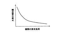
副室燃料供給手段15は、機関の要求負荷に応じて(例えば図12を参照)、燃料噴射弁16の噴射する燃料と比べて燃焼速度の大きい燃料(図11のHで示す水素)を、容積部12aへ噴射し、点火栓11の電極近傍に混合気を形成させる。
The sub-chamber fuel supply means 15 responds to the required load of the engine (see, for example, FIG. 12), with a fuel (hydrogen indicated by H in FIG. 11) having a combustion speed larger than the fuel injected by the
したがって、燃料噴射弁16は、ガソリンや、ガソリン及び水素の混合燃料など、水素より燃焼速度の小さい燃料を、吸気ポート6へ噴射するようになっている(主室4a内へ直接噴射してもよい)。
Therefore, the
本実施形態によれば、水素は、ガソリンや前記混合燃料よりも燃焼速度が大きいため、容積部12aへの噴射量が少量であっても十分に点火栓11の着火性を向上させることができる。
According to the present embodiment, since hydrogen has a higher combustion speed than gasoline and the mixed fuel, the ignition performance of the
このように、副室12内の燃焼速度や着火性が向上する分だけ、副室12を小さい容積で構成可能となり、S/V比が低下し、隔壁14からの冷却損失が低減し、これによりリーン限界を拡大可能となる。
In this way, the
なお、図12に示すように、機関の要求負荷が低いほど、容積部12a内への水素の噴射量を増加させることで、特に低負荷域(希薄域)での着火性を確保できる。
As shown in FIG. 12, the lower the required load of the engine, the higher the amount of hydrogen injected into the
1 シリンダヘッド
3 ピストン
3a キャビティ
4 燃焼室
4a 主室
5 吸気弁
6 吸気ポート
11 点火栓
12 副室
12a 容積部
13a 連通路
13b 連通路
15 副室燃料供給手段
16 燃料噴射弁
DESCRIPTION OF
Claims (11)
該主室と比して容積が小さく、シリンダヘッド側の略中央に該主室と隣接して設けられた副室と、
前記主室と副室との隔壁に設けられ、該主室と副室とをガス交換可能に連通する連通路と、
前記主室に燃料を供給する燃料供給手段と、
前記連通路を介して副室へ導かれた混合気に点火する点火手段と、
を含んで構成され、
前記副室内での着火により、前記連通路から主室内にトーチ状の火炎を噴出させて、該主室内の混合気を燃焼させる副室式内燃機関において、
前記副室は、シリンダ軸方向と直交する面内の一方向に長く延びて形成され、
前記連通路は、トーチ状の火炎を前記シリンダヘッドとピストンとの間に噴出させるような状態で、前記副室の長手方向に複数並んで形成されていることを特徴とする副室式内燃機関。 A main chamber which is the main combustion chamber;
A sub-chamber that is smaller in volume than the main chamber and is provided adjacent to the main chamber at the approximate center on the cylinder head side;
A communication path provided in a partition wall between the main chamber and the sub chamber, and communicating the main chamber and the sub chamber in a gas exchangeable manner;
Fuel supply means for supplying fuel to the main chamber;
Ignition means for igniting the air-fuel mixture guided to the sub chamber through the communication path;
Comprising
In the sub-chamber internal combustion engine in which a torch-like flame is ejected from the communication passage into the main chamber by ignition in the sub-chamber, and the air-fuel mixture in the main chamber is burned.
The sub chamber is formed to extend long in one direction in a plane perpendicular to the cylinder axial direction,
The sub-chamber internal combustion engine characterized in that a plurality of the communication passages are formed side by side in the longitudinal direction of the sub-chamber in a state in which a torch-like flame is ejected between the cylinder head and the piston. .
前記連通路は、シリンダ軸方向から見て吸排方向を指向していることを特徴とする請求項1に記載の副室式内燃機関。 The sub chamber has a longitudinal direction as a direction perpendicular to the suction and discharge directions,
2. The sub-chamber internal combustion engine according to claim 1, wherein the communication passage is oriented in an intake / exhaust direction as viewed from a cylinder axial direction.
該可変動弁機構は、副室内の掃気要求に応じて、吸気弁のリフト量を所定値以下とすることを特徴とする請求項1〜請求項10に記載の副室式内燃機関。 At least a variable valve mechanism that can change the lift amount of the intake valve,
11. The sub-chamber internal combustion engine according to claim 1, wherein the variable valve mechanism sets the lift amount of the intake valve to a predetermined value or less in response to a scavenging request in the sub-chamber.
Priority Applications (1)
| Application Number | Priority Date | Filing Date | Title |
|---|---|---|---|
| JP2008060459A JP2009215973A (en) | 2008-03-11 | 2008-03-11 | Internal combustion engine with divided combustion chamber |
Applications Claiming Priority (1)
| Application Number | Priority Date | Filing Date | Title |
|---|---|---|---|
| JP2008060459A JP2009215973A (en) | 2008-03-11 | 2008-03-11 | Internal combustion engine with divided combustion chamber |
Publications (1)
| Publication Number | Publication Date |
|---|---|
| JP2009215973A true JP2009215973A (en) | 2009-09-24 |
Family
ID=41188084
Family Applications (1)
| Application Number | Title | Priority Date | Filing Date |
|---|---|---|---|
| JP2008060459A Pending JP2009215973A (en) | 2008-03-11 | 2008-03-11 | Internal combustion engine with divided combustion chamber |
Country Status (1)
| Country | Link |
|---|---|
| JP (1) | JP2009215973A (en) |
Cited By (4)
| Publication number | Priority date | Publication date | Assignee | Title |
|---|---|---|---|---|
| WO2015093309A1 (en) * | 2013-12-16 | 2015-06-25 | 三菱重工業株式会社 | Gas engine |
| DE102018106213A1 (en) | 2017-03-16 | 2018-09-20 | Toyota Jidosha Kabushiki Kaisha | internal combustion engine |
| US10934927B2 (en) | 2018-11-26 | 2021-03-02 | Toyota Jidosha Kabushiki Kaisha | Pre-chamber type internal combustion engine |
| CN114072573A (en) * | 2019-03-27 | 2022-02-18 | 三菱自动车工业株式会社 | Auxiliary chamber type internal combustion engine |
-
2008
- 2008-03-11 JP JP2008060459A patent/JP2009215973A/en active Pending
Cited By (7)
| Publication number | Priority date | Publication date | Assignee | Title |
|---|---|---|---|---|
| WO2015093309A1 (en) * | 2013-12-16 | 2015-06-25 | 三菱重工業株式会社 | Gas engine |
| DE102018106213A1 (en) | 2017-03-16 | 2018-09-20 | Toyota Jidosha Kabushiki Kaisha | internal combustion engine |
| US10378428B2 (en) | 2017-03-16 | 2019-08-13 | Toyota Jidosha Kabushiki Kaisha | Internal combustion engine |
| DE102018106213B4 (en) | 2017-03-16 | 2021-08-19 | Toyota Jidosha Kabushiki Kaisha | Internal combustion engine |
| US10934927B2 (en) | 2018-11-26 | 2021-03-02 | Toyota Jidosha Kabushiki Kaisha | Pre-chamber type internal combustion engine |
| CN114072573A (en) * | 2019-03-27 | 2022-02-18 | 三菱自动车工业株式会社 | Auxiliary chamber type internal combustion engine |
| CN114072573B (en) * | 2019-03-27 | 2024-02-27 | 三菱自动车工业株式会社 | Sub-chamber internal combustion engine |
Similar Documents
| Publication | Publication Date | Title |
|---|---|---|
| JP7388224B2 (en) | Internal combustion engine with prechamber | |
| JP4380691B2 (en) | Sub-chamber internal combustion engine | |
| JP4601401B2 (en) | Direct injection engine | |
| JP4561522B2 (en) | Sub-chamber internal combustion engine | |
| JPS5936089B2 (en) | Internal combustion engine with auxiliary combustion chamber | |
| WO2018110326A1 (en) | Sub-chamber gas engine | |
| JP2009215973A (en) | Internal combustion engine with divided combustion chamber | |
| EP2998538A1 (en) | Pre-chamber of internal combustion engine | |
| JP2009270538A (en) | Engine | |
| JP5395622B2 (en) | Engine and pre-chamber plug attached to the engine | |
| JP2007247420A (en) | Sub-chamber internal combustion engine | |
| JP7539352B2 (en) | Gas engine | |
| WO2004099584A1 (en) | Combustion chamber structure of divided gas engine and divided gas engine | |
| JP6564288B2 (en) | piston | |
| JP7260331B2 (en) | Internal combustion engine with auxiliary combustion chamber | |
| JP4582049B2 (en) | In-cylinder injection spark ignition internal combustion engine | |
| JPH11182249A (en) | Direct injection spark ignition type internal combustion engine | |
| JP7740516B2 (en) | engine | |
| JP7846458B2 (en) | Internal combustion engine | |
| JP4257520B2 (en) | In-cylinder internal combustion engine | |
| JP7571759B2 (en) | engine | |
| JP2009270542A (en) | Engine and spark plug for engine | |
| JP2010196615A (en) | Piston for direct injection type engine | |
| JP2000064839A (en) | Precombustion chamber system gas engine | |
| JP2024089278A (en) | Internal combustion engine with auxiliary combustion chamber |