JP2009100972A - Sensor mounting band and biological information device - Google Patents
Sensor mounting band and biological information device Download PDFInfo
- Publication number
- JP2009100972A JP2009100972A JP2007276062A JP2007276062A JP2009100972A JP 2009100972 A JP2009100972 A JP 2009100972A JP 2007276062 A JP2007276062 A JP 2007276062A JP 2007276062 A JP2007276062 A JP 2007276062A JP 2009100972 A JP2009100972 A JP 2009100972A
- Authority
- JP
- Japan
- Prior art keywords
- external light
- light blocking
- band
- sensor
- buckle
- Prior art date
- Legal status (The legal status is an assumption and is not a legal conclusion. Google has not performed a legal analysis and makes no representation as to the accuracy of the status listed.)
- Withdrawn
Links
- 230000000903 blocking effect Effects 0.000 claims abstract description 84
- 238000004804 winding Methods 0.000 claims abstract description 23
- 238000001514 detection method Methods 0.000 claims description 15
- 239000002783 friction material Substances 0.000 claims description 11
- 230000003014 reinforcing effect Effects 0.000 claims description 9
- 239000011162 core material Substances 0.000 description 21
- 238000005259 measurement Methods 0.000 description 10
- 239000008280 blood Substances 0.000 description 6
- 210000004369 blood Anatomy 0.000 description 6
- 210000000078 claw Anatomy 0.000 description 5
- 230000033001 locomotion Effects 0.000 description 5
- 238000003825 pressing Methods 0.000 description 5
- 238000005452 bending Methods 0.000 description 4
- 239000004744 fabric Substances 0.000 description 4
- 239000004973 liquid crystal related substance Substances 0.000 description 4
- 238000000034 method Methods 0.000 description 4
- 238000004519 manufacturing process Methods 0.000 description 3
- 239000000463 material Substances 0.000 description 3
- 230000005540 biological transmission Effects 0.000 description 2
- 210000004204 blood vessel Anatomy 0.000 description 2
- 238000010586 diagram Methods 0.000 description 2
- 230000002787 reinforcement Effects 0.000 description 2
- 230000035945 sensitivity Effects 0.000 description 2
- 102000001554 Hemoglobins Human genes 0.000 description 1
- 108010054147 Hemoglobins Proteins 0.000 description 1
- 230000001133 acceleration Effects 0.000 description 1
- QVGXLLKOCUKJST-UHFFFAOYSA-N atomic oxygen Chemical compound [O] QVGXLLKOCUKJST-UHFFFAOYSA-N 0.000 description 1
- 230000036772 blood pressure Effects 0.000 description 1
- 230000036760 body temperature Effects 0.000 description 1
- 239000003086 colorant Substances 0.000 description 1
- 238000000295 emission spectrum Methods 0.000 description 1
- 238000005516 engineering process Methods 0.000 description 1
- 239000011521 glass Substances 0.000 description 1
- 238000012423 maintenance Methods 0.000 description 1
- 238000012986 modification Methods 0.000 description 1
- 230000004048 modification Effects 0.000 description 1
- 229910052757 nitrogen Inorganic materials 0.000 description 1
- IJGRMHOSHXDMSA-UHFFFAOYSA-N nitrogen Substances N#N IJGRMHOSHXDMSA-UHFFFAOYSA-N 0.000 description 1
- 229910052760 oxygen Inorganic materials 0.000 description 1
- 239000001301 oxygen Substances 0.000 description 1
- 229910052698 phosphorus Inorganic materials 0.000 description 1
- 239000011574 phosphorus Substances 0.000 description 1
- 238000012545 processing Methods 0.000 description 1
- 239000011347 resin Substances 0.000 description 1
- 229920005989 resin Polymers 0.000 description 1
- 239000007787 solid Substances 0.000 description 1
Images


Landscapes
- Measuring Pulse, Heart Rate, Blood Pressure Or Blood Flow (AREA)
Abstract
【課題】バックルを用いてバンドを巻き付け方向と逆に締め付けるようにしたとしても、
バックルの部分から光が入り込まないようにすることができるセンサ装着用バンド及び生
体情報機器を提供する。
【解決手段】伸縮性を有し、利用者の生体情報を検出するセンサ30を腕部Tまたは指部
Sとの間に挟み込む態様で巻き付けられるセンサ装着用バンドであって、巻き付け方向に
おける一端側にバックル42を取り付け、他端側の先端部41bをバックル42に挿通し
て腕部Tまたは指部Sに巻き付けたときに、腕部Tまたは指部Sとバックル42との間に
挟まれる態様で位置し、センサ30への入光を遮る外光遮断部41aを設けた。
【選択図】図6[PROBLEMS] Even if a band is tightened using a buckle in the direction opposite to the winding direction,
Provided are a sensor mounting band and a biological information device that can prevent light from entering from a buckle portion.
A sensor mounting band that is wound in such a manner that a sensor 30 that has elasticity and detects biometric information of a user is sandwiched between an arm portion T or a finger portion S, and is one end side in the winding direction. When the buckle 42 is attached to the arm part T and the tip part 41b on the other end side is inserted into the buckle 42 and wound around the arm part T or the finger part S, it is sandwiched between the arm part T or the finger part S and the buckle 42. The external light blocking part 41a that blocks the incident light to the sensor 30 is provided.
[Selection] Figure 6
Description
本発明は、利用者の腕部または指部に生体情報を検出するセンサを装着可能なセンサ装
着用バンド及び生体情報機器に関する。
The present invention relates to a sensor mounting band and a biological information device in which a sensor for detecting biological information can be mounted on a user's arm or finger.
従来より、利用者の腕部(リスト部)または指部に装着して利用者の脈拍を含む生体情
報を測定する生体情報機器が知られている。この生体情報機器は、生体情報を光によって
検出するセンサと、このセンサを検出部位に固定するために、利用者の腕部または指部に
巻き付けられるセンサ装着用バンドと、センサからの検出情報を表示するための本体部と
を備えている。
上述したセンサは、より正確な精度で生体情報を検出するために、上述した検出部位に
適正な圧力(センサが精度よく検出可能な圧力)で押圧される必要がある。この圧力は、
例えば、センサ装着用バンドを伸縮可能な素材で形成し、このバンドを装着時に腕部また
は指部の周方向に締め付けることにより、この締め付ける張力を利用して得ることができ
る。また、センサに適正な圧力を加えるためには、センサ装着用バンドに所定の張力を加
えればよいことになる。(例えば、特許文献1または特許文献2参照)。
2. Description of the Related Art Conventionally, there is known a biometric information device that is worn on a user's arm (list unit) or finger and measures biometric information including a user's pulse. This biological information device includes a sensor that detects biological information by light, a sensor mounting band that is wrapped around a user's arm or finger in order to fix the sensor to a detection site, and detection information from the sensor. And a main body for displaying.
In order to detect biological information with more accurate accuracy, the above-described sensor needs to be pressed against the above-described detection portion with an appropriate pressure (a pressure that can be accurately detected by the sensor). This pressure is
For example, the sensor mounting band can be formed of a stretchable material, and the band can be obtained by tightening the band in the circumferential direction of the arm or finger when the band is mounted. In order to apply an appropriate pressure to the sensor, a predetermined tension may be applied to the sensor mounting band. (For example, refer to
一方、バンドを腕部などに巻き付ける際、巻き付け作業を容易にするためにバックルを
用いたものが知られている。具体的には、バンドの長手方向の一端側にバックルを設け、
バンドを腕部などに巻き付けた後にバンドの他端側の先端をバックルに通すと共に、バン
ドの先端をバンドの巻き付け方向と逆に向けて締め込むものがある。
In some cases, after the band is wound around an arm or the like, the tip on the other end side of the band is passed through a buckle, and the tip of the band is tightened in the direction opposite to the band winding direction.
光によって検出するセンサを用いる場合、外部からの光によって検出誤差が生じないよ
うに、検出部位とセンサとの間に外部から光が入り込まないようにすることが好ましい。
しかしながら、上述のバックルを用いた構造では、バンドの一端側に位置するバックルの
部分でバンドの先端をバンド巻き付け方と逆に向けて締め込むため、バックルの部分をバ
ンドで覆うことができずに隙間が生じてしまい、この隙間から外部の光が入り込んでしま
うおそれがある。
In the case of using a sensor that detects light, it is preferable to prevent light from entering between the detection site and the sensor so that a detection error does not occur due to light from the outside.
However, in the structure using the above-described buckle, since the tip of the band is tightened in the opposite direction to the band winding method at the buckle portion located on one end side of the band, the buckle portion cannot be covered with the band. There is a possibility that a gap is formed, and external light enters through this gap.
そこで、本発明の目的は、上述した従来の技術が有する課題を解消し、バックルを用い
てバンドを巻き付け方向と逆に締め付けるようにしたとしても、バックルの部分から光が
入り込まないようにすることができるセンサ装着用バンド及び生体情報機器を提供するこ
とにある。
Therefore, an object of the present invention is to eliminate the problems of the conventional technology described above and prevent light from entering from the buckle portion even if the band is tightened in the opposite direction to the winding direction using the buckle. An object is to provide a sensor mounting band and a biological information device.
上記課題を解決するため、本発明は、伸縮性を有し、利用者の生体情報を検出するセン
サを腕部または指部との間に挟み込む態様で巻き付けられるセンサ装着用バンドであって
、巻き付け方向における一端側にバックルを取り付け、他端側の先端を前記バックルに挿
通して前記腕部または指部に巻き付けたときに、前記腕部または指部と前記バックルとの
間に挟まれる態様で位置し、前記センサへの入光を遮る外光遮断部を設けたことを特徴と
する。
In order to solve the above-described problems, the present invention provides a sensor mounting band that has elasticity and is wound in such a manner that a sensor for detecting biological information of a user is sandwiched between an arm part or a finger part. In a mode in which a buckle is attached to one end in the direction and the tip of the other end is inserted through the buckle and wrapped around the arm or finger, and is sandwiched between the arm or finger and the buckle An external light blocking part is provided, which is positioned and blocks light entering the sensor.
この場合において、前記外光遮断部は、前記バックルの取り付け位置を変更せずに前記
一端側の先端を巻き付け方向へ延ばす態様で形成されていてもよい。
また、センサ装着用バンドであって、前記外光遮断部は、この外光遮断部以外の部分と
比較して、屈曲し難い固さに形成されていてもよい。
また、センサ装着用バンドであって、前記外光遮断部の外側部に補強部材を装着しても
よい。
さらに、センサ装着用バンドであって、前記外光遮断部を袋状に形成し、この外光遮断
部の内部に補強部材を挿入することもできる。
さらにまた、センサ装着用バンドであって、前記外光遮断部の表面を低摩擦材で形成す
ることもできる。
In this case, the external light blocking portion may be formed in such a manner that the tip on the one end side extends in the winding direction without changing the attachment position of the buckle.
Moreover, it is a band for sensor mounting | wearing, Comprising: The said external light interruption | blocking part may be formed in the hardness which cannot be bent easily compared with parts other than this external light interruption | blocking part.
Moreover, it is a band for sensor mounting | wearing, Comprising: You may mount | wear a reinforcement member on the outer side part of the said external light shielding part.
Further, in the sensor mounting band, the external light blocking portion may be formed in a bag shape, and a reinforcing member may be inserted into the external light blocking portion.
Furthermore, in the sensor mounting band, the surface of the external light blocking portion can be formed of a low friction material.
利用者の腕部または指部から生体情報を検出するセンサと、伸縮性を有し、前記腕部ま
たは指部との間に前記センサを挟み込む態様で巻き付けられ、この巻き付けられた張力に
よって前記センサを前記腕部または指部に押圧するバンドと、前記センサの検出情報に従
って生体情報値を表示する本体部とを備えた生体情報機器において、前記バンドは、巻き
付け方向における一端側にバックルを取り付け、他端側の先端を前記バックルに挿通して
前記腕部または指部に巻き付けたときに、前記腕部または指部と前記バックルとの間に挟
まれる態様で位置し、前記センサへの入光を遮る外光遮断部を設けたことを特徴とする。
A sensor for detecting biological information from a user's arm part or finger part, and a sensor that is stretchable and is wound in such a manner that the sensor is sandwiched between the arm part or finger part. In a biological information device comprising a band that presses the arm or finger against the body and a main body that displays a biological information value according to detection information of the sensor, the band has a buckle attached to one end side in the winding direction, When the tip of the other end is inserted through the buckle and wound around the arm or finger, the light is incident on the sensor and is positioned between the arm or finger and the buckle. An outside light blocking part is provided to block the light.
この場合において、前記外光遮断部は、前記バックルの取り付け位置を変更せずに前記
一端側の先端を巻き付け方向へ延ばす態様で形成されていてもよい。
また、生体情報機器であって、前記外光遮断部は、この外光遮断部以外の部分と比較し
て、屈曲し難い固さに形成されていてもよい。
また、生体情報機器であって、前記外光遮断部の外側部に補強部材を装着してもよい。
さらに、生体情報機器であって、前記外光遮断部を袋状に形成し、この外光遮断部の内
部に補強部材を挿入することもできる。
さらにまた、生体情報機器であって、前記外光遮断部の表面を低摩擦材で形成すること
もできる。
In this case, the external light blocking portion may be formed in such a manner that the tip on the one end side extends in the winding direction without changing the attachment position of the buckle.
Moreover, it is a biological information apparatus, Comprising: The said external light interruption | blocking part may be formed in the hardness which cannot be bent easily compared with parts other than this external light interruption | blocking part.
Moreover, it is a biological information apparatus, Comprising: You may mount | wear with a reinforcement member in the outer side part of the said external light shielding part.
Further, in the biological information device, the external light blocking portion may be formed in a bag shape, and a reinforcing member may be inserted into the external light blocking portion.
Furthermore, in the biological information device, the surface of the external light blocking portion can be formed of a low friction material.
他方、生体情報機器であって、前記バンドは、前記本体部を腕部に装着するための本体
部装着用バンドを兼ねるようにしてもよい。
On the other hand, in the biological information device, the band may also serve as a main body mounting band for mounting the main body on the arm.
本発明では、センサ装着用バンドは、巻き付け方向における一端側にバックルを取り付
け、他端側の先端を前記バックルに挿通して前記腕部または指部に巻き付けたときに、前
記腕部または指部と前記バックルとの間に挟まれる態様で位置し、前記センサへの入光を
遮る外光遮断部を設けているので、バックルにセンサ装着用バンドを挿通させたときに生
じるバックルの部分での隙間を外光遮断部で塞ぐことができ、この隙間の部分から外部の
光が入り込まないようにすることができる。その結果、外部から入り込む光によってセン
サの検出誤差が生じないようにすることができる。
In the present invention, when the sensor mounting band is attached to a buckle on one end side in the winding direction and the tip on the other end side is inserted through the buckle and wound around the arm portion or finger portion, the arm portion or finger portion Since the external light blocking part that blocks light entering the sensor is provided, the buckle part that occurs when the sensor mounting band is inserted through the buckle The gap can be closed by the external light blocking portion, and external light can be prevented from entering through the gap. As a result, it is possible to prevent the detection error of the sensor from occurring due to light entering from the outside.
以下、本発明の実施の形態に係るセンサ装着用バンド40および生体情報機器1につい
て説明する。なお、本実施の形態で示す生体情報機器1とは、生体情報として脈拍を用い
、生体情報値として脈拍数を検出するものである。この生体情報機器1は、例えば、利用
者が運動(ランニングなど)をしているときであっても、生体情報(本実施例では脈拍数
とする)を確認することができるものである。
Hereinafter, the
図1は、本実施の形態に係る生体情報機器1を利用者の腕部T(リスト部)に装着した
状態を示す概要図である。
生体情報機器1は、腕時計構造を有する本体部10と、この本体部10に接続されるケ
ーブル20と、このケーブル20の先端に設けられた脈拍センサ30と、この脈拍センサ
30を利用者の腕部Tに挟み込む態様でその腕部Tに装着するためのセンサ装着用バンド
40とを備えている。このセンサ装着用バンド40は、図1に示すように、本体部10の
付近であって、腕部Tの延在方向に並べて装着されている。
FIG. 1 is a schematic diagram showing a state in which the
The
本体部10には、腕時計における12時方向から腕に巻きついてその6時方向で固定さ
れるリストバンド12が設けられている。このリストバンド12によって、本体部10は
、腕に着脱自在に装着されている。また、本体部10の6時の側には、コネクタ部70が
設けられており、このコネクタ部70にケーブル20の一端側に設けられたコネクタピー
ス80が着脱自在に取り付けられるようになっている。
The
図2は、本体部10を単体で示す平面図であって、リストバンド12やケーブル20な
どを取り外した状態を示している。
本体部10は、樹脂製の時計ケース11(本体ケース)を備えている。時計ケース11
の表面側には、現在時刻や日付に加えて、走行時や歩行時のピッチ、及び脈拍数などの脈
波情報などを表示するELバックライト付きの液晶表示装置13(表示装置)が設けられ
ている。液晶表示装置13には、表示面の左上側に位置する第1のセグメント表示領域1
31、右上側に位置する第2のセグメント表示領域132、右下側に位置する第3のセグ
メント表示領域133、及び左下側に位置するドット表示領域134が構成されており、
ドット表示領域134では、各種の情報をグラフィック表示可能である。
時計ケース11の内部には、ピッチを求めるための体動センサ(図示せず)が内蔵され
ている。この体動センサとしては、加速度センサなどを用いることができる。
FIG. 2 is a plan view showing the
The
In addition to the current time and date, a liquid crystal display device 13 (display device) with an EL backlight for displaying pulse wave information such as a pitch during running or walking and a pulse rate is provided on the surface side of the display. ing. The liquid
31, a second
In the
A body movement sensor (not shown) for obtaining the pitch is built in the
また、時計ケース11の内部には、各種の制御やデータ処理を行う制御部5が設けられ
ている。この制御部5は、上述した体動センサによる検出結果(体動信号)および脈拍セ
ンサ30による検出結果(脈波信号)に基づいて、測定対象者である利用者の脈拍数を解
析し、液晶表示装置13で表示する。この場合において、制御部5には、計時回路も構成
されているため、通常時刻なども液晶表示装置13に表示可能となっている。
In addition, a
時計ケース11の外周部には、入力装置を構成し、時刻合わせや表示モードの切り換え
などの外部操作を行うためのボタンスイッチ111〜115が設けられている。また、時
計ケースの表面には、同じく、入力装置を構成する、大きめのボタンスイッチ116、1
17が構成されている。
また、生体情報機器1の電源は、時計ケース11に内蔵されているボタン形の小型の電
池59であり、ケーブル20は、電池59から脈拍センサ30に電力を供給するとともに
、脈拍センサ30の検出結果を時計ケース11の制御部5に入力している。
On the outer periphery of the
17 is configured.
The power source of the
図3は、脈拍センサ30の断面図である。
脈拍センサ30は、そのケース体の内部に回路基板35が配置されており、この回路基
板35には、LED31、フォトトランジスタ32、その他の電子部品が実装されている
。この脈拍センサ30では、センサ枠36の上面部分(実質的な脈波信号検出部)にガラ
ス板からなる透光板34によって光透過窓が形成されている。そして、この透光板34に
対して、LED31及びフォトトランジスタ32は、それぞれ発光面及び受光面を透光板
34の方に向けている。このため、透光板34の外側表面441(指表面との接触面/セ
ンサ面)に指表面を密着させると、LED31は、指表面の側に向けて光を発する。これ
とともに、フォトトランジスタ32は、LED31が発した光のうち利用者の腕部から反
射してくる光を受光可能である。
FIG. 3 is a cross-sectional view of the
The
本実施形態では、LED31として、InGaN系(インジウム−ガリウム−窒素系)
の青色LEDを用いてあり、その発光スペクトルは、450nmに発光ピークを有してい
る。さらにLED31の発光波長領域は、350nmから600nmまでの範囲にある。
かかる発光特性を有するLED31に対応させて、本例では、フォトトランジスタ32と
して、GaAsP系(ガリウム−砒素−リン系)のフォトトランジスタを用いている。フ
ォトトランジスタ32自身の受光波長領域は、主要感度領域が300nmから600nm
までの範囲にあって、300nm以下にも感度領域がある。
In the present embodiment, the
Blue LED, and its emission spectrum has an emission peak at 450 nm. Furthermore, the emission wavelength region of the
In this example, a GaAsP-based (gallium-arsenic-phosphorus-based) phototransistor is used as the
There is also a sensitivity region at 300 nm or less.
このように構成した脈拍センサ30を、センサ装着用バンド40によって腕部Tに装着
し、この状態で、LED31から指に向けて光を照射すると、この光が血管に届いて血液
中のヘモグロビンによって光の一部が吸収され、一部が反射する。指(血管)から反射し
てきた光は、フォトトランジスタ32によって受光され、その受光量変化が血量変化(血
液の脈波)に対応する。すなわち、血量が多いときには、反射光が弱くなる一方、血量が
少なくなると、反射光が強くなるので、反射光強度の変化を検出すれば、脈拍数を含む各
種生体情報などを計測できる。
When the
図4(a)は、センサ装着用バンド40を単体で示す正面図、図4(b)は、(a)の
側面図である。また、図5は、センサ装着用バンド40を腕部に巻き付けた状態の斜視図
である。
センサ装着用バンド40は、腕部Tの周方向に長手方向を向けて巻き付けられるバンド
部41と、このバンド部41を締め付ける際にバンド部41が引っ掛けられるバックル部
42と、このバックル部42をバンド部41に取り付けるための保持部43とを備えてい
る。なお、図4(a)において、バンド部41の裏面41Xが利用者の腕部Tと接する面
であり、表面41Yが外側に向くように取り付けられる。
FIG. 4A is a front view showing the
The
バックル部42は、図4(a)に示すように、棒状の部材を折り曲げて略矩形状の輪を
形成したものである。この輪の幅方向の長さは、バンド部41の幅方向の長さよりも大き
くなっており、この輪の中にバンド部41を挿通できるようになっている。
保持部43は、帯状部材で輪を形成したものであり、この保持部43の基端部43aが
バンド部41に固定されている。また、この保持部43は、前述した輪の中にバックル部
42の1辺を巻くようにして保持している。これにより、バックル部42が保持部43を
介してバンド部41に取り付けられている。
As shown in FIG. 4A, the
The holding
バンド部41は、伸縮性を有している。すなわち、このバンド部41が腕部Tに巻き付
けられて締め付けられる際に、バンド部41はその長手方向に伸びるようになる。また、
このバンド部41の長手方向の寸法Lは、あらゆる利用者の腕部Tの太さまたは周方向の
長さを十分に考慮して、十分に長く形成してある。一方、バンド部41の幅方向(長手方
向と直交する方向)の長さL2は、脈拍センサ30の長さL1(図3参照)よりも十分に
長くなるように形成されている。すなわち、脈拍センサ30が装着されるときに、このセ
ンサ装着用バンド40によって脈拍センサ30の全体が覆われるようになっている。これ
により、脈拍センサ30は、センサ装着用バンド40の外部から遮光された状態で利用者
の腕部Tに装着されるようになる。
The
The length L in the longitudinal direction of the
また、このバンド部41には、上述した保持部43がバンド部41に固定されている基
端部43aからバンド部41をその長手方向の一方の先端に向けて延ばす態様で外光遮断
部41aが一体に形成されている。この外光遮断部41aは、図5に示すように、バンド
部41を腕部Tに巻き付けた状態において、この腕部Tとバックル部42との間に挟まれ
る態様で位置するようになる。また、この外光遮断部41aの延在する長さD1は、バッ
クル部42の長さD2よりも長く形成されており、バックル部42の下側(腕部Tと向き
合う側)に外光遮断部41aが隙間ないように敷かれるようになる。
In addition, the
このバンド部41の表面41Y側には、外光遮断部41aと反対側の先端部41bにマ
ジックテープ(登録商標)の爪部44が設けられている。一方、この爪部44の終端から
基端部43aまでの間には、この爪部44が取り付けられるマジックテープ(登録商標)
の生地部45が設けられている。この爪部44と生地部45は、既知の通り、人間の力で
自由に固定したり剥がしたりすることができるものである。これにより、バンド部41の
固定位置を自由に調整、変更することができるようになっている。
On the
このバンド部41を腕部Tに巻き付ける手順としては、図5に示すように、バンド部4
1を腕部Tに巻き付けるときにバンド部41の先端部41bをバックル部42の輪の中に
挿通させ、この先端部41bを巻き付け方向と反対側の方向に折り返して引っ張り、上述
した爪部44を生地部45に取り付ける。このようにバンド部41を巻き付け方向と反対
側に引っ張ることにより、バンド部41に張力を発生させることができる。一方、脈拍セ
ンサ30には、このバンド部41に発生した張力によって、腕部Tに押圧する押圧力Fが
作用することになる。
As a procedure for winding the
1 is wound around the arm portion T, the
一方、この脈拍センサ30は、精度良く脈拍数を検出可能な圧力で腕部Tに押圧される
必要がある。そのため、このバンド部41には、脈拍センサ30に適正な押圧力Fを付与
するために、図4(a)に示すように、巻き付ける前に腕部Tの周方向の長さを測定する
測定部200と、この測定部で測定した長さに基づいて固定位置(バンド部41に適度な
張力を与えることのできる固定位置)を表示する固定指示部210とが設けられている。
On the other hand, the
測定部200は、図4(a)に示すように、3つの測定領域201(図4(a)の右側
から、符号201a、201b、201cで示す)で構成されている。これらの測定領域
201a、201b、201cは、バンド部41の長手方向(バンド部41の巻き付け方
向)に所定の長さ毎に区分けされており、それぞれの領域が異なる色によって表示されて
いる。
一方、固定指示部210についても、図4(a)に示すように、3つの固定指示領域2
11(図4(a)の右側から、符号211a、211b、211cで示す)で構成されて
いる。また、これらの固定指示領域211a、211b、211cは、バンド部41の長
手方向(バンド部41の巻き付け方向)に所定の長さ毎に区分けされており、それぞれの
領域が異なる色によって表示されている。
As shown in FIG. 4A, the
On the other hand, as shown in FIG. 4A, the fixing
11 (indicated by
これらの3段階に区分けされた固定指示領域211a、211b、211cは、それぞ
れの測定領域201a、201b、201cとそれぞれ対応している。詳細には、測定領
域201a(緑色)と固定指示領域211a(緑色)、測定領域201b(青色)と固定
指示領域211b(青色)、測定領域201c(赤色)と固定指示領域211c(赤色)
とがそれぞれ対応しており、測定部200の色と同色に表示された色の部分に対応させて
バンド部41を固定指示部210に固定することにより、脈拍センサ30に適正な押圧力
Fを作用させることができる。
These three fixed
And the
また、脈拍センサ30は、図5に示すように、保持部43の基端部43aの近傍に配置
される。これは、脈拍センサ30に押圧力Fを作用させるときに、バンド部41の張力を
調整する基準点となるバックル部42(より詳細には、基端部43a)の付近に配置した
方が、より正確な押圧力Fを管理することができるからである。
Moreover, the
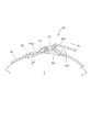
図6は、外光遮断部41aを拡大して示す斜視図である。また、図7は、図5に示す外
光遮断部41aを拡大して示す断面図であって、隙間48が発生した状態を示している。
バンド部41に適正な張力を作用させる過程において、バックル部42に挿通させたバ
ンド部41を巻き付け方向と反対側の方向に引っ張ると、バンド部41の裏面41Xと、
外光遮断部41aの表面41Zとに摩擦が生じ、図7に示すように、外光遮断部41aが
上側にくの字形状に屈曲し、腕部Tと外光遮断部41aとの間に隙間48が生じてしまう
おそれがある。この隙間48が発生すると、センサ装着用バンド40の外側から光が隙間
48内に入り込んでしまい、脈拍センサ30にこの光が当たると、検出誤差が生じてしま
う。
そのため、外光遮断部41aは、図6に示すように、その端部に開口部46を有する袋
状に形成され、この袋状の内部に補強部材としての機能を有する芯材47が挿入されるよ
うになっている。この芯材47を挿入することによって、外光遮断部41aがバンド部4
1の他の部分(外光遮断部41a以外の部分)と比較して屈曲し難い固さになり、上述し
た隙間48の発生を防止するようにしている。
FIG. 6 is an enlarged perspective view showing the external
In the process of applying an appropriate tension to the
As shown in FIG. 7, friction is generated on the
Therefore, as shown in FIG. 6, the external
Compared with the other part of 1 (the part other than the external
この芯材47は、略矩形形状をなしており、図6に示すように、外光遮断部41aの延
在する長さD1と同じ長さまたは若干小さい長さD3に形成されている。また芯材47の
幅方向の長さD4は、袋状部分の内幅と同じ長さまたは若干小さい長さに形成されている
。これらの寸法に形成することにより、芯材47が外光遮断部41aの開口部46から挿
入可能になっている。他方、芯材47の材料及び厚みは、上述した外光遮断部41aの屈
曲を抑制することができ、かつ、腕部Tに装着したときに腕部Tの形状に沿って変形する
ことができる範囲内で自由に決定することができる。例えば、材料としてプラスチックな
どが使用可能である。
As shown in FIG. 6, the
また、外光遮断部41aの表面41Zは、バンド部41の裏面41Xとの間に生じる摩
擦を低減させるために、外光遮断部41a以外の裏面41X、表面41Yと比較して摩擦
係数の小さな低摩擦材料で構成されている。また、摩擦を低減させるために、表面41Z
を凹凸のない滑らかな面で形成している。
なお、この摩擦を低減させる構造としては、表面41Zに低摩擦材で形成された摺動部
材を設ける構造であってもよく、さらには表面41Zに低摩擦材料を塗布したものであっ
てもよい。
Further, the
Is formed on a smooth surface without unevenness.
The structure for reducing the friction may be a structure in which a sliding member formed of a low friction material is provided on the
本発明の実施の形態に係るセンサ装着用バンド40および生体情報機器1によれば、巻
き付け方向における一端側にバックル部42を設け、他端側の先端部41bをバックル部
42に挿通して腕部Tに巻き付けたときに、腕部Tとバックル部42との間に挟まれる態
様で位置し、脈拍センサ30への入光を遮る外光遮断部41aを設けているので、バック
ル部42にセンサ装着用バンド40を挿通させたときに生じるバックル部42での隙間を
外光遮断部41aで塞ぐことができ、この隙間の部分から脈拍センサ30に外部の光が入
り込まないようにすることができる。その結果、外部から入り込む光によって脈拍センサ
30の検出誤差が生じないようにすることができる。
According to the
また、外光遮断部41aは、基端部43aからバンド部41をその長手方向の一方の先
端に向けて延ばす態様で一体に形成されているので、外光遮断部41aをバンド部41と
別体で構成する場合と比較して、部品点数の削減を図ることができる。また、バンド部4
1を製造する際に、一緒に外光遮断部41aを製作することができるので、製作が容易に
なる。
Further, since the external
When manufacturing 1, since the external
さらに、外光遮断部41aを袋状に形成し、この外光遮断部41aの内部に補強部材で
ある芯材47を挿入しているので、外光遮断部41aがバンド部41の他の部分(外光遮
断部41a以外の部分)と比較して屈曲し難い固さになり、外光遮断部41aが上側にく
の字形状に屈曲して、腕部Tと外光遮断部41aとの間に隙間48が発生するのを防止す
ることができる。その結果、隙間48から入り込む光によって脈拍センサ30の検出誤差
が生じないようにすることができる。
Furthermore, since the external
さらにまた、外光遮断部41aの表面41Zを低摩擦材で形成しているので、バンド部
41の裏面41Xと当接したときの摩擦を低減させることができる。そのため、外光遮断
部41aが上側にくの字形状に屈曲して、腕部Tと外光遮断部41aとの間に隙間48が
発生するのを防止することができる。その結果、隙間48から入り込む光によって脈拍セ
ンサ30の検出誤差が生じないようにすることができる。
Furthermore, since the
以上、本発明の実施の形態について述べたが、本発明は既述の実施形態に限定されるも
のではなく、本発明の技術思想に基づいて各種の変形および変更が可能である。
本実施の形態では、センサ装着用バンド40を利用者の腕部Tに巻き付けるようにした
が、図8および図9に示すように、利用者の指部Sに巻き付けるようにしてもよい。この
場合、指部Sとは、5本の指のうち測定に適した任意の指を示す。また、脈拍センサ30
は、腕部Tに装着される場合と同様に、センサ装着用バンド40によって指部Sとの間に
挟まれる態様で、かつ外部から遮光されるように脈拍センサ30の全体を覆う態様で巻き
付けられ、センサ装着用バンド40に生じる張力によって脈拍センサ30が指部Sに押圧
されるようになる。このように、脈拍センサ30を指の根元に装着することにより、ケー
ブル20を短くすることができ、ケーブル20がランニング中に邪魔にならないようにす
ることができる。
Although the embodiments of the present invention have been described above, the present invention is not limited to the above-described embodiments, and various modifications and changes can be made based on the technical idea of the present invention.
In the present embodiment, the
Is wound in a manner that is sandwiched between the finger portion S by the
また、本実施の形態では、図1に示すように、センサ装着用バンド40と本体部10と
を腕部の延在方向に並べて装着しているが、センサ装着用バンド40に本体部10を取り
付けて、これらを一体に構成してもよい。これによれば、本体部10を装着するためのリ
ストバンド12を設ける必要がなくなり、生体情報機器1の製造コストを低減させること
ができる。また、ケーブル20をバンド部41の内部に埋め込むことにより、ケーブル2
0の引き回しを不要とし、コストを低減させることもできる。また、利用者にケーブル2
0が嵩張ることによる違和感を与えることがない。
Further, in the present embodiment, as shown in FIG. 1, the
It is also possible to reduce the cost by eliminating the need for zero routing. Also,
There is no discomfort due to 0 being bulky.
一方、本実施の形態では、外光遮断部41aが基端部43aからバンド部41をその長
手方向の一方の先端に向けて延ばす態様で一体に形成するように構成しているが、バンド
部41と別体であってもかまわない。例えば、外光遮断部41aをバンド部41の基端部
43aに後工程で縫いつけて構成してもよい。これによっても、実施の形態に記載の構造
と同様に、脈拍センサ30に外部からの光が入り込み難くすることができる。
On the other hand, in the present embodiment, the external
さらに、芯材47の寸法D4を外光遮断部41a内に形成した袋状部分の内幅とほぼ等
しくなるように形成しているが、この芯材47は、外光遮断部41aの延在方向における
屈曲を防止するものであるため、芯材47のD3寸法を確保しておけば、芯材47の寸法
D4を袋状部分の内幅いっぱいまで大きくする必要はない。すなわち、芯材47の幅方向
においける一部であってもよい。さらには、芯材を幅方向で分割して複数設けてあっても
よい。
Furthermore, although the dimension D4 of the
また、外光遮断部41aを袋状にして芯材47を挿入する構造にしなくても、外光遮断
部41aの固さを、この外光遮断部41a以外の部分と比較して屈曲し難い固さに形成す
ることもできる。例えば、バンド部41と外光遮断部41aとを一体に製作する際に、こ
の外光遮断部41aの厚みだけ他の部分と比較して厚く形成することで、他の部分と比較
して固くすることができる。または、予め芯材を外光遮断部41aに埋め込んでおくこと
もできる。また、補強部材である芯材47を外光遮断部41aの外側部に縫い付けたりし
て装着しておくこともできる。さらに、芯材の方を袋状に形成して外光遮断部41aの外
側に差し込むようにしたり、芯材を帯状に形成して、外光遮断部41aの外側部に着脱自
在に巻き付ける(装着する)ようにしてもよい。これにより、外光遮断部41aを屈曲し
難い固さに形成することができる。
なお、この芯材47を外光遮断部41aの表面41Zの外側に設ける場合には、この芯
材47の表面を低摩擦材で形成して、外光遮断部41aが上側にくの字形状に屈曲して、
腕部Tと外光遮断部41aとの間に隙間48が発生するのを防止することもできる。
Further, even if the external
In addition, when providing this
It is also possible to prevent the
また、本実施の形態では、外光遮断部41aの表面41Zを低摩擦材で形成しているが
、この表面41Zと接触するバンド部41の裏面41Xを低摩擦材で形成するものであっ
てもよい。これにより、外光遮断部41aを屈曲し難くすることができる。
In the present embodiment, the
他方、本実施の形態では、生体情報として脈拍数を表示するように説明したが、脈拍数
に限らない。例えば、生体情報として、体温、血圧、脈波、動脈血中の酸素飽和度、体動
等が具体例として挙げられる。
On the other hand, in this Embodiment, it demonstrated that the pulse rate was displayed as biometric information, but it is not restricted to a pulse rate. For example, as biological information, body temperature, blood pressure, pulse wave, oxygen saturation in arterial blood, body movement, and the like can be given as specific examples.
1…生体情報機器、10…本体部、11…時計ケース、12…リストバンド(本体部装
着バンド)、20…ケーブル、30…脈拍センサ、40…センサ装着用バンド、41…バ
ンド部、41X…裏面、41Y…表面、41Z…外光遮断部の表面、41a…外光遮断部
、41b…先端部、42…バックル部、43…保持部、43a…基端部、44…爪部、4
5…生地部、46…開口部、47…芯材、48…隙間、200…測定部、210…固定指
示部、S…指部、T…腕部。
DESCRIPTION OF
DESCRIPTION OF
Claims (13)
態様で巻き付けられるセンサ装着用バンドであって、
巻き付け方向における一端側にバックルを取り付け、他端側の先端を前記バックルに挿
通して前記腕部または指部に巻き付けたときに、前記腕部または指部と前記バックルとの
間に挟まれる態様で位置し、前記センサへの入光を遮る外光遮断部を設けたことを特徴と
するセンサ装着用バンド。 A sensor mounting band that has elasticity and is wound in such a manner that a sensor for detecting biological information of a user is sandwiched between an arm part or a finger part,
A mode in which a buckle is attached to one end side in the winding direction and the tip of the other end side is inserted into the buckle and wound around the arm portion or the finger portion, and is sandwiched between the arm portion or the finger portion and the buckle A sensor mounting band, characterized in that an external light blocking portion is provided which blocks light incident on the sensor.
付け方向へ延ばす態様で形成されていることを特徴とする請求項1に記載のセンサ装着用
バンド。 2. The sensor mounting band according to claim 1, wherein the external light blocking portion is formed in a form in which a tip of the one end side is extended in a winding direction without changing an attachment position of the buckle.
徴とする請求項1または請求項2に記載のセンサ装着用バンド。 The sensor mounting band according to claim 1 or 2, wherein the outside light blocking portion is formed in a bag shape, and a reinforcing member is inserted into the outside light blocking portion.
2に記載のセンサ装着用バンド。 The sensor mounting band according to claim 1 or 2, wherein a reinforcing member is mounted on an outer side of the external light blocking unit.
ていることを特徴とする請求項1または請求項2に記載のセンサ装着用バンド。 3. The sensor mounting band according to claim 1, wherein the external light blocking portion is formed to be harder to bend than portions other than the external light blocking portion.
いずれか1つに記載のセンサ装着用バンド。 The sensor mounting band according to any one of claims 1 to 5, wherein a surface of the external light blocking portion is formed of a low friction material.
たは指部との間に前記センサを挟み込む態様で巻き付けられ、この巻き付けられた張力に
よって前記センサを前記腕部または指部に押圧するバンドと、前記センサの検出情報に従
って生体情報値を表示する本体部とを備えた生体情報機器において、
前記バンドは、巻き付け方向における一端側にバックルを取り付け、他端側の先端を前
記バックルに挿通して前記腕部または指部に巻き付けたときに、前記腕部または指部と前
記バックルとの間に挟まれる態様で位置し、前記センサへの入光を遮る外光遮断部を設け
たことを特徴とする生体情報機器。 A sensor for detecting biological information from a user's arm part or finger part, and a sensor that is stretchable and is wound in such a manner that the sensor is sandwiched between the arm part or finger part. In a biological information device comprising a band that presses the arm portion or the finger portion and a body portion that displays a biological information value according to detection information of the sensor,
The band has a buckle attached to one end in the winding direction, and when the tip of the other end is inserted through the buckle and wound around the arm or finger, the band or the buckle A biological information apparatus, characterized in that an external light blocking unit is provided which is positioned in a manner sandwiched between layers and blocks light incident on the sensor.
付け方向へ延ばす態様で形成されていることを特徴とする請求項7に記載の生体情報機器
。 The biological information apparatus according to claim 7, wherein the external light blocking unit is formed in a form in which a tip on the one end side is extended in a winding direction without changing an attachment position of the buckle.
徴とする請求項7または請求項8に記載の生体情報機器。 The biological information device according to claim 7 or 8, wherein the external light blocking part is formed in a bag shape, and a reinforcing member is inserted into the external light blocking part.
8に記載の生体情報機器。 The biological information device according to claim 7 or 8, wherein a reinforcing member is attached to an outer side of the external light blocking unit.
ていることを特徴とする請求項7または請求項8に記載の生体情報機器。 The biological information device according to claim 7 or 8, wherein the external light blocking unit is formed to be harder to bend than portions other than the external light blocking unit.
のいずれか1つに記載の生体情報機器。 The surface of the external light blocking part is formed of a low friction material.
The biological information device according to any one of the above.
とを特徴とする請求項7から請求項12のいずれか1つに記載の生体情報機器。 The biological information device according to any one of claims 7 to 12, wherein the band also serves as a main body mounting band for mounting the main body on an arm.
Priority Applications (1)
| Application Number | Priority Date | Filing Date | Title |
|---|---|---|---|
| JP2007276062A JP2009100972A (en) | 2007-10-24 | 2007-10-24 | Sensor mounting band and biological information device |
Applications Claiming Priority (1)
| Application Number | Priority Date | Filing Date | Title |
|---|---|---|---|
| JP2007276062A JP2009100972A (en) | 2007-10-24 | 2007-10-24 | Sensor mounting band and biological information device |
Publications (1)
| Publication Number | Publication Date |
|---|---|
| JP2009100972A true JP2009100972A (en) | 2009-05-14 |
Family
ID=40703390
Family Applications (1)
| Application Number | Title | Priority Date | Filing Date |
|---|---|---|---|
| JP2007276062A Withdrawn JP2009100972A (en) | 2007-10-24 | 2007-10-24 | Sensor mounting band and biological information device |
Country Status (1)
| Country | Link |
|---|---|
| JP (1) | JP2009100972A (en) |
Cited By (1)
| Publication number | Priority date | Publication date | Assignee | Title |
|---|---|---|---|---|
| CN104739385A (en) * | 2013-12-25 | 2015-07-01 | 精工爱普生株式会社 | Biometric information measuring apparatus |
-
2007
- 2007-10-24 JP JP2007276062A patent/JP2009100972A/en not_active Withdrawn
Cited By (1)
| Publication number | Priority date | Publication date | Assignee | Title |
|---|---|---|---|---|
| CN104739385A (en) * | 2013-12-25 | 2015-07-01 | 精工爱普生株式会社 | Biometric information measuring apparatus |
Similar Documents
| Publication | Publication Date | Title |
|---|---|---|
| US11918327B2 (en) | Sphygmomanometer, blood pressure measurement method, and device | |
| US10299726B2 (en) | Bodily information measurement apparatus | |
| US10172529B2 (en) | Systems and methods for detecting physiological information of a user | |
| US11850031B2 (en) | Sphygmomanometer, blood pressure measurement method, and device | |
| JP5895993B2 (en) | Biological information measuring device | |
| US20200000351A1 (en) | Smart watch accessory for improved ppg heart rate reading | |
| JP2004351107A (en) | Portable medical measuring instrument | |
| JP2016096955A (en) | Biological information measurement apparatus | |
| JP2004344367A (en) | Medical purpose measuring instrument | |
| CN107106036A (en) | Systems and methods for optical isolation in measuring physiological parameters | |
| JP2009100897A (en) | Sensor mounting band and biological information device | |
| JP5061848B2 (en) | Sensor mounting band and biological information device | |
| WO2010082444A1 (en) | Cover member, probe, and living body information measuring device using probe | |
| JP5040678B2 (en) | Sensor mounting supporter and arm mounted biological information measuring device | |
| JP2007190122A (en) | Biological information measuring apparatus | |
| CN111093496B (en) | Biological information measuring instrument | |
| JP2009100972A (en) | Sensor mounting band and biological information device | |
| JP3524998B2 (en) | Pulse wave measurement device | |
| EP2499966B1 (en) | Probe | |
| CN210204710U (en) | Fingerstall type blood pressure, blood oxygen and heart rate measuring device | |
| JP2017104252A (en) | Mounting body for biological information measurement device | |
| JP2000296117A (en) | Fingertip photoelectric pulse wave sensor | |
| US20170340275A1 (en) | Wearable device | |
| JP2009101043A (en) | Sensor mounting band and biological information device | |
| JP2009189681A (en) | Supporter size gauge |
Legal Events
| Date | Code | Title | Description |
|---|---|---|---|
| A300 | Withdrawal of application because of no request for examination |
Free format text: JAPANESE INTERMEDIATE CODE: A300 Effective date: 20110104 |