JP2009036128A - Multi-link variable compression ratio engine - Google Patents
Multi-link variable compression ratio engine Download PDFInfo
- Publication number
- JP2009036128A JP2009036128A JP2007202008A JP2007202008A JP2009036128A JP 2009036128 A JP2009036128 A JP 2009036128A JP 2007202008 A JP2007202008 A JP 2007202008A JP 2007202008 A JP2007202008 A JP 2007202008A JP 2009036128 A JP2009036128 A JP 2009036128A
- Authority
- JP
- Japan
- Prior art keywords
- piston
- link
- compression ratio
- engine
- cylinder
- Prior art date
- Legal status (The legal status is an assumption and is not a legal conclusion. Google has not performed a legal analysis and makes no representation as to the accuracy of the status listed.)
- Pending
Links
Images


Landscapes
- Transmission Devices (AREA)
- Shafts, Cranks, Connecting Bars, And Related Bearings (AREA)
- Pistons, Piston Rings, And Cylinders (AREA)
Abstract
【課題】潤滑オイルの燃焼室への流出を防止するとともに、ブローバイガスによるオイル劣化を抑制することができる複リンク式可変圧縮比エンジンを提供する。
【解決手段】シリンダ内を往復動するピストン21を有するエンジン1において、ピストン21に形成されるピストンロッド22と、ピストンロッド22とクランクシャフト36とを複数のリンクで連結し、車両の運転状態に応じてリンクの姿勢を変化させることで圧縮比を可変とする圧縮比可変機構30と、ピストン21の下側においてシリンダ内をクランク室24から仕切るとともに、ピストンロッド22が摺動自由に貫通する隔壁50と、ピストン21の下面とシリンダ壁と隔壁50とにより形成され、ピストン21の往復動に伴って拡縮する拡縮室60と、拡縮室60を吸気系と連通して、拡縮室60に漏れ込んだブローバイガスを吸気系に還流する還流通路13と、を備える。
【選択図】図1Provided is a multi-link variable compression ratio engine capable of preventing lubricating oil from flowing into a combustion chamber and suppressing oil deterioration due to blow-by gas.
In an engine 1 having a piston 21 that reciprocates in a cylinder, a piston rod 22 formed on the piston 21, a piston rod 22 and a crankshaft 36 are connected by a plurality of links to bring the vehicle into an operating state. Correspondingly, the compression ratio variable mechanism 30 that changes the compression ratio by changing the posture of the link, and a partition that partitions the cylinder from the crank chamber 24 below the piston 21 and through which the piston rod 22 penetrates freely. 50, the lower surface of the piston 21, the cylinder wall, and the partition wall 50. The expansion / contraction chamber 60 expands / contracts as the piston 21 reciprocates, and the expansion / contraction chamber 60 communicates with the intake system and leaks into the expansion / contraction chamber 60. And a return passage 13 for returning the blowby gas to the intake system.
[Selection] Figure 1
Description
本発明は、複リンク式可変圧縮比エンジンに関する。 The present invention relates to a multi-link variable compression ratio engine.
従来から車両のエンジンでは、ピストンの往復動によってピストンとシリンダとの隙間から潤滑オイルが燃焼室に流出して、潤滑オイルの消費量が増大する等の問題があった。 Conventionally, in a vehicle engine, there has been a problem that lubricating oil flows out into the combustion chamber from the gap between the piston and the cylinder due to the reciprocating movement of the piston, and the consumption amount of the lubricating oil increases.
特許文献1に記載の発明はオイルリング溝内にエキスパンダスプリングを備え、オイルリングの張力を負荷に応じて調整することで、ピストンリングとシリンダライナとの焼き付きを防止するとともに潤滑オイルの消費量を低減する。
しかしながら、特許文献1に記載の発明では、エキスパンダスプリングの制御に応答遅れなどが生じると、潤滑オイルの燃焼室内への流出を確実に低減することはできない。また、未燃焼の燃料などを含むブローバイガスが、ピストンとシリンダとの隙間を通って燃焼室からクランク室に流れ込み、潤滑オイルのオイル劣化が生じるという問題がある。
However, in the invention described in
そこで、本発明は、潤滑オイルの燃焼室への流出を防止するとともに、ブローバイガスによるオイル劣化を抑制することができる複リンク式可変圧縮比エンジンを提供することを目的とする。 SUMMARY OF THE INVENTION An object of the present invention is to provide a multi-link variable compression ratio engine that can prevent lubricating oil from flowing out into a combustion chamber and suppress oil deterioration due to blow-by gas.
本発明は、以下のような解決手段によって前記課題を解決する。なお、理解を容易にするために本発明の実施形態に対応する符号を付するが、これに限定されるものではない。 The present invention solves the above problems by the following means. In addition, in order to make an understanding easy, although the code | symbol corresponding to embodiment of this invention is attached | subjected, it is not limited to this.
本発明は、シリンダ内を往復動するピストン(21)を有するエンジン(1)において、前記ピストン(21)に形成されるピストンロッド(22)と、前記ピストンロッド(22)とクランクシャフト(36)とを複数のリンクで連結し、車両の運転状態に応じてリンクの姿勢を変化させることで圧縮比を可変とする圧縮比可変機構(30)と、前記ピストン(21)の下側においてシリンダ内をクランク室(24)から仕切るとともに、前記ピストンロッド(22)が摺動自由に貫通する隔壁(50)と、前記ピストン(21)の下面とシリンダ壁と前記隔壁(50)とにより形成され、前記ピストン(21)の往復動に伴って拡縮する拡縮室(60)と、前記拡縮室(60)を吸気系と連通して、前記拡縮室(60)に漏れ込んだブローバイガスを吸気系に還流する還流通路(13)と、を備える。 The present invention provides an engine (1) having a piston (21) that reciprocates in a cylinder, a piston rod (22) formed on the piston (21), the piston rod (22), and a crankshaft (36). Are connected by a plurality of links, and the compression ratio variable mechanism (30) for changing the compression ratio by changing the posture of the link according to the driving state of the vehicle, and the cylinder in the lower side of the piston (21) Is formed by a partition wall (50) through which the piston rod (22) freely slides, a lower surface of the piston (21), a cylinder wall, and the partition wall (50). The expansion / contraction chamber (60) that expands / contracts with the reciprocating motion of the piston (21), and the expansion / contraction chamber (60) communicates with an intake system so as to leak into the expansion / contraction chamber (60). It includes a recirculation passage for recirculating to the intake system (13) to Baigasu, the.
本発明によれば、ピストンの下方に隔壁を配置し、ピストンロッドが隔壁を介して摺動するため、ピストンに生じるサイドスラスト荷重が低減する。したがって、ピストンスカートを短縮化でき、潤滑オイルがなくてもピストンはシリンダ内を往復動することができる。そのため、潤滑オイルの消費量が確実に低減でき、排気性能を改善することができる。 According to the present invention, the partition wall is arranged below the piston, and the piston rod slides through the partition wall, so that the side thrust load generated in the piston is reduced. Therefore, the piston skirt can be shortened, and the piston can reciprocate in the cylinder without lubricating oil. Therefore, the consumption amount of lubricating oil can be reliably reduced, and the exhaust performance can be improved.
また、ピストンの下方に吸気系と連通する拡縮室を備えるので、ピストンの往復動によって拡縮室に生じる圧力を利用してブローバイガスを吸気系に還流させることができ、ブローバイガスによる潤滑オイルのオイル劣化を抑制できる。 In addition, since the expansion / contraction chamber communicated with the intake system is provided below the piston, the blow-by gas can be recirculated to the intake system using the pressure generated in the expansion / contraction chamber by the reciprocating motion of the piston. Deterioration can be suppressed.
さらに、車両の運転状態に応じて圧縮比を最適に制御するので、熱効率を向上させることができ、燃費性能を改善することが可能となる。 Furthermore, since the compression ratio is optimally controlled according to the driving state of the vehicle, the thermal efficiency can be improved and the fuel efficiency can be improved.
以下、図面を参照して本発明の実施の形態について説明する。 Embodiments of the present invention will be described below with reference to the drawings.
図1は、本実施形態の複リンク式可変圧縮比エンジンを示す概略図である。 FIG. 1 is a schematic view showing a multi-link variable compression ratio engine of the present embodiment.
複リンク式可変圧縮比エンジン1は、ピストン21のサイドスラスト荷重を低減するクロスヘッド機構20と、圧縮比を可変とする複リンク機構30とをシリンダブロック10の内部に備える。なお、シリンダブロック10の上部に取付けられるシリンダヘッドの図示は省略している。
The multi-link variable
クロスヘッド機構20は、ピストン21と、ピストンロッド22と、アッパリンク31とから構成される。
The
ピストン21はピストンスカートが無く、あるいはごく僅かであって、シリンダブロック10のシリンダ11の内部に収装される。このピストン21の冠面と、シリンダ11の壁面と、図示しないシリンダヘッドの内壁とによって燃焼室2を仕切る。
The
ピストン21の下部には、ピストンロッド22がピストン21と同軸に一体形成される。このピストンロッド22は、ピストン21と分割可能に設けるようにしてもよい。また、ピストン21の下側には、シリンダ11の内部をピストン21の下方とクランク室24との間で仕切る隔壁としてのスラストサポート50が設けられる。そのため、ピストンロッド22はスラストサポート50を貫通し、スラストサポート50の孔51によって摺動自由に支持される。ここで、ピストンロッド22とスラストサポート50の孔51とは、潤滑性の高いオイルシール52によってシールされている。
A
ピストン21のピストンロッド22の下端は、ピストンピン23を介して複リンク機構30のアッパリンク31の上端と連結する。このアッパリンク31の下端は、連結ピン34を介してロアリンク32の一端と連結する。そして、ロアリンク32の他端は、連結ピン35を介してコントロールリンク33と連結する。このロアリンク32は、図中左右の2部材から分割可能に構成され、ほぼ中央に連結孔32aを有する。連結孔32aには、クランクシャフト36のクランクピン36aが挿入される。
The lower end of the
クランクシャフト36は、クランクピン36a、ジャーナル36b及びカウンターウェイト36cを備える。クランクピン36aの中心はジャーナル36bの中心から所定量偏心しており、このクランクピン36aにロアリンク32が回転自在に連結する。ジャーナル36bは、シリンダブロック10とラダーフレーム37とによって回転自在に支持される。ジャーナル36bの軸心は、クランクシャフト36の軸心と一致している。カウンターウェイト36cは、クランクアームに一体形成されて、ピストン運動の回転1次振動成分を低減する。
The crankshaft 36 includes a
コントロールリンク33の上端は、連結ピン35を介してロアリンク32に対して回動自在に連結する。また、コントロールリンク33の下端は、連結ピン38を介して、クランクシャフト36と平行に配置されるコントロールシャフト41に連結する。連結ピン38は、コントロールシャフト41の軸心から所定量偏心しており、コントロールリンク33がその偏心した連結ピン38を軸心として揺動する。このコントロールシャフト41は、その外周にギア42を形成する。このギア42がピニオン43と噛合する。ピニオン43は、シリンダブロック10の側部に取付けられたアクチュエータ44の回転軸45に設けられている。
The upper end of the
このように構成される複リンク式可変圧縮比エンジン1では、ピストン21の往復運動はピストンロッド22によってアッパリンク31に伝達され、さらにロアリンク32を介してクランクシャフト36の回転運動に変化される。この場合には、ロアリンク32はクランクピン36aを中心軸として揺動しながら、クランクシャフト36の中心に対して図中反時計回りに回転する。ロアリンク32に連結するコントロールリンク33は、その下端に連結するコントロールシャフト41の連結ピン38を支点として揺動する。コントロールシャフト41と連結ピン38とは偏心しているため、アクチュエータ44によってコントロールシャフト41が回転すると、連結ピン38が移動する。この連結ピン38の移動によってコントロールリンク33の揺動中心が変化するため、これによりアッパリンク31及びロアリンク32の傾斜を変えることができ、ピストン21の上死点位置を所定の範囲内で任意に調整できる。このように、複リンク式可変圧縮比エンジン1では、ピストン21の上死点位置を調整することによって機械圧縮比が可変となる。
In the multi-link variable
一方、この複リンク式可変圧縮比エンジン1は、ピストン21とシリンダ11との摺動隙間を通って燃焼室からクランク室側へ流出したブローバイガスを、ピストン21の往復動によって図示しない吸気通路に還流する拡縮室60を有する。
On the other hand, in this multi-link variable
拡縮室60は、シリンダ11の壁面と、ピストン21の下面と、スラストサポート50の上面とによって形成される。スラストサポート50はピストン21の下死点位置よりも下側に固定され、スラストサポート50の上面には凹部53が形成される。また、シリンダブロック10の一方の側部には貫通孔12が設けられ、この貫通孔12に連通管13が接続する。連通管13は、スラストサポート50の凹部53と貫通孔12とを介して、拡縮室60と図示しない吸気通路とを連通する。そして、複リンク式可変圧縮比エンジン1の拡縮室60は、ピストン21の往復動に伴って容積が拡大と縮小を繰り返し、燃焼室2から拡縮室60へ流れ込んだブローバイガスを吸気系に還流する。
The expansion /
上記のような複リンク式可変圧縮比エンジン1は、車両の運転状態に応じて燃料噴射量、点火時期、スロットルバルブ開度や機械圧縮比を制御するため、コントローラ70を備える。コントローラ70はCPU、ROM、RAM及びI/Oインタフェースから構成されている。
The multi-link variable
このコントローラ70には、図示しないノックセンサやクランク角センサ等の車両運転状態を検出する各種センサの出力が入力する。そして、コントローラ70は、これら出力に基づいて図示しないスロットルバルブ、燃料噴射弁及び点火プラグを制御する。また、コントローラ70は、予め設定された機械圧縮比マップを参照し、車両の運転状態に応じて機械圧縮比を最適に制御して、熱効率を向上させて燃費性能を改善する。例えば、低回転速度・小トルクでは機械圧縮比を高くして熱効率の向上を図り、高回転速度・大トルク側では機械圧縮比を低くしてノッキングの防止を図る。
The
ところで、従来から車両のエンジンでは、潤滑オイルがピストン21の往復動によってピストン21とシリンダ11との隙間を通って燃焼室2に流出して潤滑オイルの消費量が増大したり、ブローバイガスがクランク室24に流れ込んで、潤滑オイルのオイル劣化が生じたりするという問題がある。
By the way, in a conventional vehicle engine, the lubricating oil flows into the
しかしながら、複リンク式可変圧縮比エンジン1では、図1に示したように、複リンク機構30とスラストサポート50とを組み合わせることで、上記問題を解消している。
However, in the multi-link variable
図2は、複リンク式可変圧縮比エンジン1における潤滑オイルの消費量の低減を説明する図である。
FIG. 2 is a diagram for explaining a reduction in the amount of consumption of lubricating oil in the multi-link variable
複リンク式可変圧縮比エンジン1では、複リンク機構30のアライメントを選択することによって、図2に示すように燃焼室2の内部の圧力が最大値Pmaxとなる膨張行程前半において、ピストンロッド22と連結するアッパリンク31を直立姿勢(ピストンロッド22の軸心L1に対するアッパリンク31の軸心L2の傾き角度θが0°に近い状態)に維持することができる。そのため、アッパリンク31の傾き角度θに応じてピストン21に生じるサイドスラスト荷重を大幅に低減することができる。さらに、複リンク式可変圧縮比エンジン1のピストンロッド22は、スラストサポート50の孔51に対して摺動するため、ピストン21に生じるサイドスラスト荷重のほとんどをスラストサポート50が受ける。
In the multi-link variable
このように、複リンク式可変圧縮比エンジン1では、ピストン21に生じるサイドスラスト荷重は大幅に低減されるので、ピストン21のピストンスカート長さを短縮することができる。そのため、ピストン21は潤滑オイルがなくてもシリンダ11の内部を往復動することができる。したがって、ピストン21の往復動によって潤滑オイルが燃焼室に流出することを防止でき、潤滑オイルの消費量を確実に低減させて、排気性能を改善することが可能となる。
As described above, in the multi-link variable
なお、複リンク式可変圧縮比エンジン1において、ピストン21のピストンリング25がシリンダ壁に対して潤滑しやすいようにピストンリングの表面処理を行うようにしてもよい。
In the multi-link variable
次に、複リンク式可変圧縮比エンジン1における潤滑オイルのオイル劣化の抑制について図3を参照して説明する。
Next, suppression of oil deterioration of the lubricating oil in the multi-link variable
図3は、複リンク式可変圧縮比エンジン1の拡縮室60の動作を示す図である。図3(A)は、圧縮行程において、ピストン21が下死点から上死点へ移動するときのブローバイガスの流れを示す。また、図3(B)は、膨張行程において、ピストン21が上死点から下死点へ移動するときのブローバイガスの流れを示す。
FIG. 3 is a view showing the operation of the expansion /
図3(A)に示すように、ピストン21が下死点から上死点に上昇すると、拡縮室60は拡大して燃焼室2が収縮するので、燃焼室内の混合気が圧縮される。この圧縮された混合気がピストン上死点付近で点火プラグによって爆発燃焼すると、ピストン21が上死点から下死点に向けて押し下げられるとともに、未燃焼の燃料などを含むブローバイガスがピストン21とシリンダ11との隙間を通って燃焼室2から拡縮室60に流入する。そして、図3(B)に示すように、ピストン21が上死点から下死点に下降すると、燃焼室2が拡大して拡縮室60が収縮する。このように、拡縮室60が収縮すると、拡縮室内のブローバイガスが加圧され、そのブローバイガスは連通管13に流れ込み、連通管13を通って図示しない吸気通路に戻る。
As shown in FIG. 3A, when the
このように、複リンク式可変圧縮比エンジン1は、燃焼室2からのブローバイガスを、拡縮室60の拡縮動作によって吸気系に還流(以下「ブローバイガスの内部還流」という。)させる(内部還流手段)。また、ピストン21のピストンロッド22は、スラストサポート50のオイルシール52によって摺動自在にシールされているので、上記したブローバイガスが拡縮室60からクランク室24へ流れ込むことも抑制される。そのため、複リンク式可変圧縮比エンジン1では、ブローバイガスによるクランク室内の潤滑オイルのオイル劣化が抑制される。
Thus, the multi-link variable
なお、上記のように拡縮室60の拡縮によってブローバイガスの内部還流を行う場合、拡縮室60に圧力変動が生じてピストン21のポンピングが増大するため、気筒ごとに形成される貫通孔12をシリンダブロック内に形成した通路によって互いに連通し、圧力変動を抑制してポンピングロス低減を図るようにしてもよい。
When the blow-by gas is internally recirculated by the expansion / contraction of the expansion /
ところで、潤滑オイルの消費量を低減したり、オイル劣化を抑制したりするためにクロスヘッド機構20を備えると、複リンク式可変圧縮比エンジン1が大形化してしまう。
By the way, if the
そこで、クロスヘッド機構を備えたことによるエンジン高さの増大について、ピストンとクランクシャフトとを一本のコンロッドで連結するエンジン(以下「従来エンジン」と称する)を参考にして説明する。 Therefore, an increase in engine height due to the provision of the crosshead mechanism will be described with reference to an engine (hereinafter referred to as “conventional engine”) in which a piston and a crankshaft are connected by a single connecting rod.
図4は、従来エンジンの構成を示す図である。 FIG. 4 is a diagram showing a configuration of a conventional engine.
従来エンジン100は、図4(A)に示すように、ピストン121とコンロッド131とを備える。ピストン121は、ピストンピン123を介してコンロッド131の上端と連結する。コンロッド131の下端は、クランクシャフト136のジャーナル136bから所定量偏心しているクランクピン136aと接続する。
The
このような従来エンジン100において、クロスヘッド機構120によるブローバイガスの内部還流を行う場合には、図4(B)に示すように、ピストン121にピストンロッド122を形成し、ピストンロッド122とコンロッド131とをピストンピン123を介して連結する。クロスヘッド機構120を備えた従来エンジン100は、ピストンピン123が図4(A)と同位置に設定されるため、ピストン121にピストンロッド122を形成した分だけエンジン高さが高くなる。
In such a
このエンジン高さを抑制するために、コンロッド131を短くして連桿比を小さくすることが考えられる。ここで、連桿比は以下の数式によって表される。
In order to suppress the engine height, it is conceivable to shorten the connecting

しかしながら、従来エンジン100において、コンロッド131の長さを短くして連桿比を小さくすると、ピストンストローク特性が単振動から大きくはずれて、ピストン121の往復動やクランクピン136aの回転運動によって生じる振動(以下「慣性2次振動」と称する)が増大してしまう。このように従来エンジン100では、慣性2次振動が悪化するために連桿比を小さくすることができず、クロスヘッド機構120を備える場合にはエンジン高さの増大が避けられない。
However, in the
これに対して、複リンク式可変圧縮比エンジン1では、複リンク機構30のアライメントを選択して、図5に示すようにピストンストローク特性(実線A)を従来エンジン100のピストンストローク特性(破線B)よりも略単振動に近い特性とすることで、ピストンストローク特性に基づく慣性2次振動を低減する。このように、ピストンがストローク中央から上昇して上死点を経て再びストローク中央まで下降したときのクランク角度と、ストローク中央から下降して下死点を経て再びストローク中央まで上昇したときのクランク角度とを略同一とし、ピストンストローク特性を略単振動とする構成の詳細については、特開2005−180302号公報を参照されたい。
On the other hand, in the multi-link variable
複リンク式可変圧縮比エンジン1における慣性2次振動のY方向成分の低減について図6を参照して説明する。
The reduction of the Y direction component of the inertial secondary vibration in the multi-link variable
図6(A)は、慣性2次振動のY方向成分を低減する複リンク機構30を模式的に示す図である。ここで、ピストン21の往復運動する方向をY方向、それに直行する方向をX方向とする。図6(B)はピストンピン23に生じる慣性2次振動のY方向成分を示す。また、図6(C)は連結ピン34に生じる慣性2次振動のY方向成分を示す。図6(B)及び図6(C)では、横軸はピストン21のシリンダ内での位置を示し、縦軸は慣性2次振動のY方向成分を示す。
FIG. 6A schematically shows a
複リンク式可変圧縮比エンジン1では、図6(B)に示すように、ピストン21が上死点又は下死点にある場合に、アッパリンク31の揺動によってピストンピン23に生じるY方向の慣性2次振動が最大となる複リンク機構30のアライメントを選択する。また、図6(C)に示すように、ピストン21が上死点及び下死点にある場合に、コントロールリンク33の揺動によって連結ピン34に生じるY方向の慣性2次振動が最小となる複リンク機構30のアライメントを選択する。このように複リンク機構30のアライメントを選択することによって、ピストンピン23に生じる慣性2次振動のY方向成分を連結ピン34に生じる慣性2次振動のY方向成分で打ち消すことができ、慣性2次振動を低減することができる。
In the multi-link variable
このように複リンク式可変圧縮比エンジン1では、慣性2次振動を低減できるので、クロスヘッド機構20を備えても、ピストンピン23と連結ピン34との距離を短く設定(連桿比を小さく設定)することで、エンジン高さを抑制することができる。
As described above, in the multi-link variable
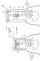
図7は、複リンク式可変圧縮比エンジン1のピストン21の往復動を模式的に示す図である。図7(A)は、ピストン21が上死点にある場合を示す。また、図7(B)は、ピストン21が下死点にある場合を示す。座標の中心は、クランクシャフト36の回転中心を示す。なお、図7(A)及び図7(B)では、ブローバイガスの内部還流の詳細な構成は、説明の便宜上省略している。
FIG. 7 is a diagram schematically showing reciprocation of the
図7(A)及び図7(B)に示されるシリンダ11は、クロスヘッド機構20を備えない複リンク式可変圧縮比エンジン1で使用されるシリンダ11と略同一の高さである。複リンク式可変圧縮比エンジン1では、慣性2次振動が低減できるような複リンク機構30のアライメント選択しているため、連桿比を小さく、具体的にはピストンピン23と連結ピン34との距離を短く設定することができる。そのため、図7(B)に示すように、ピストン21の下死点位置において、ピストンピン23をクランクシャフト36の回転中心と略同程度の位置まで下げることができる。そのため、シリンダ11がクロスヘッド機構20を備えない複リンク式可変圧縮比エンジン1で使用されるシリンダ11と略同一の高さのものであっても、図7(A)及び図7(B)に示す通り、ピストン21は従来のピストンストロークのまま往復運動することができる。
The
以上により、本実施形態の複リンク式可変圧縮比エンジン1は下記の効果を得ることができる。
As described above, the multi-link variable
本発明よれば、ピストン21の下方にスラストサポート50を配置し、ピストンロッド22がスラストサポート50を介して摺動するため、ピストン21に生じるサイドスラスト荷重が低減する。したがって、ピストンスカートを短縮化でき、潤滑オイルがなくてもピストン21はシリンダ内を往復動することができる。そのため、潤滑オイルの消費量が確実に低減でき、排気性能を改善することができる。
According to the present invention, since the
また、ピストン21の下方に吸気通路と連通する拡縮室60を備え、ピストン21の往復動によって拡縮室60に生じる圧力を利用してブローバイガスを吸気系に還流させる。そのため、ブローバイガスのクランク室24への流入が抑えられ、ブローバイガスによる潤滑オイルのオイル劣化を抑制することができる。
In addition, an expansion /
さらに、複リンク式可変圧縮比エンジン1では、複リンク機構30のアライメントを選択することによって慣性2次振動を低減でき、連桿比を小さく設定することができる。そのため、ピストン21の下死点位置において、ピストンピン23をクランクシャフト36の回転中心と略同程度の位置まで下げることができ、クロスヘッド機構20を備えてもエンジン高さの増大を抑制することができる。
Further, in the multi-link variable
本発明は上記した実施形態に限定されずに、その技術的な思想の範囲内において種々の変更がなし得ることは明白である。 It is obvious that the present invention is not limited to the above-described embodiment, and various modifications can be made within the scope of the technical idea.
例えば、ピストン21のピストンリング25の合口部25aをダブルアングル構造とすることで、ピストン21のシリンダ11に対するシール性能を向上させるようにしてもよい。
For example, you may make it improve the sealing performance with respect to the
図8は、ピストン21に装着されるピストンリング25を示す図である。
FIG. 8 is a view showing a
図8(A)に示すように、ピストンリング25は周方向の一部に合口部25aを有する。このピストンリング25の合口部25aの端面を平坦面とすると、ピストンリング25を装着したピストン21が、シリンダ11の内部を下死点から上死点に向かって上昇すると、矢印に示すように燃焼室2内の混合気などが合口部25aを通って流出してしまうので、ピストン21のシリンダ11に対するシール性能は低い。
As shown to FIG. 8 (A), the
そのため、図8(B)に示すように、ピストンリング25の合口部25aの一方の端面の角部に三角形形状の断面を有する凸部25bを形成し、その凸部25bと対応する他方の端面の角部にも同断面形状の凹部25cが形成して、ピストンリング25をピストン21に装着するときに、凸部25bと凹部25cとが組合うようにピストンリング25を構成する(ダブルアングル構造)。なお、図8(B)において、凸部25b及び凹部25cの断面は直角三角形形状となっているが、これに限られるものではなく長方形形状などにするようにしてもよい。
Therefore, as shown in FIG. 8B, a
このダブルアングル構造のピストンリング25を、図8(C)に示すように凸部25bがピストン冠面側の反対側に位置するようにピストン21に装着(順組み)することでシール性能が向上する。つまり、ピストン21がシリンダ11の内部を下死点から上死点に向かって上昇して、混合気などが合口部25aに流れ込んでも、図8(C)の矢印に示すように凸部25bによって混合気の流れを遮断することができ、燃焼室内のシール性を向上させることができる。
Sealing performance is improved by attaching (in order) the
しかしながら、ピストン21がシリンダ11を摺動するために潤滑オイルを必要とする従来のエンジンにおいては、上記のようにピストンリング25をピストン21に順組みして燃焼室内のシール性を向上させると、燃焼室内の混合気などの流出を抑制することはできるが、却って燃焼室2の内部に流出した潤滑オイルがクランク室側に戻りにくくなって、潤滑オイル消費量が増大してしまうという問題がある。そのため、そのような従来のエンジンにおいては、このダブルアングル構造のピストンリング25を、図8(D)に示すように凸部25bがピストン冠面側に位置するようにピストン21に装着(逆組み)する。そうすると、ピストン21が上昇したときに、燃焼室内に流入した潤滑オイルは、図8(D)の矢印のように合口部25aを通ってクランク室側に戻りやすくなる。そのため、ピストン21がシリンダ11を摺動するために潤滑オイルを必要とする従来エンジンでは、ピストンリング25を順組みで使用せずに、逆組みで使用することによってシール性能を若干低下させて、潤滑オイル消費量が増大するのを抑制している。
However, in a conventional engine that requires lubricating oil for the
これに対して、複リンク式可変圧縮比エンジン1のピストン21では、複リンク機構30とスラストサポート50とによってスラスト荷重を低減させるので、ピストン21は潤滑オイルがなくてもシリンダ11内を往復動することができる。そのため、従来エンジンのようにピストンリング25を逆組みして潤滑オイル消費量を低減する必要がない。したがって、複リンク式可変圧縮比エンジン1では、ピストンリング25を順組みにしてシール性能を向上させ、熱効率をより改善することが可能となる。
In contrast, in the
1 複リンク式可変圧縮比エンジン
2 燃焼室
11 シリンダ
12 貫通孔
13 連通管(還流通路)
20 クロスヘッド機構
21 ピストン
22 ピストンロッド
24 クランク室
25 ピストンリング
25a 合口部
25b 凸部
25c 凹部
30 複リンク機構(圧縮比可変機構)
31 アッパリンク(第1リンク)
32 ロアリンク(第2リンク)
33 コントロールリンク(第3リンク)
36 クランクシャフト
41 コントロールシャフト
44 アクチュエータ
50 スラストサポート(隔壁)
52 オイルシール
60 拡縮室
70 コントローラ
1 Multi-link variable
20
31 Upper link (1st link)
32 Lower link (second link)
33 Control link (3rd link)
36
52
Claims (7)
前記ピストンに形成されるピストンロッドと、
前記ピストンロッドとクランクシャフトとを複数のリンクで連結し、車両の運転状態に応じてリンクの姿勢を変化させることで圧縮比を可変とする圧縮比可変機構と、
前記ピストンの下側においてシリンダ内をクランク室から仕切るとともに、前記ピストンロッドが摺動自由に貫通する隔壁と、
前記ピストンの下面とシリンダ壁と隔壁とにより形成され、前記ピストンの往復動に伴って拡縮する拡縮室と、
前記拡縮室を吸気系と連通して、前記拡縮室に漏れ込んだブローバイガスを吸気系に還流する還流通路と、
を備えることを特徴とするエンジン。 In an engine having a piston that reciprocates in a cylinder,
A piston rod formed on the piston;
The piston rod and the crankshaft are connected by a plurality of links, and the compression ratio variable mechanism that makes the compression ratio variable by changing the posture of the link according to the driving state of the vehicle,
Partitioning the inside of the cylinder from the crank chamber on the lower side of the piston, and a partition wall through which the piston rod slides freely;
An expansion / contraction chamber formed by a lower surface of the piston, a cylinder wall, and a partition wall, which expands / contracts as the piston reciprocates;
A recirculation passage that communicates the expansion chamber with the intake system and recirculates the blow-by gas leaked into the expansion chamber to the intake system;
An engine comprising:
前記ピストンロッドに揺動自由に連結する第1リンクと、
前記第1リンクに回動自由に連結するとともに、クランクシャフトに回転自由に装着される第2リンクと、
前記クランクシャフトと平行にシリンダブロックに回転自由に支持され、その回転軸心に対して偏心する偏心軸部を有するコントロールシャフトと、
前記第2リンクに連結ピンを介して回転自由に連結されるとともに、前記コントロールシャフトの偏心軸部を揺動軸心として揺動可能な第3リンクとを備え、
車両の運転状態に応じて前記コントロールシャフトを回転し、偏心軸部の位置を変更して、エンジンの機械圧縮比を変更するようにした、
ことを特徴とする請求項1から3のいずれか一つに記載のエンジン。 The compression ratio variable mechanism is
A first link that is pivotably coupled to the piston rod;
A second link rotatably connected to the first link and rotatably mounted on the crankshaft;
A control shaft having an eccentric shaft portion that is rotatably supported by the cylinder block in parallel with the crankshaft and is eccentric with respect to the rotation axis;
A third link that is rotatably connected to the second link via a connecting pin, and that is capable of swinging with the eccentric shaft portion of the control shaft as a swing axis;
The control shaft is rotated according to the driving state of the vehicle, the position of the eccentric shaft portion is changed, and the mechanical compression ratio of the engine is changed.
The engine according to any one of claims 1 to 3, wherein
前記燃焼室内の圧力が最大値となる付近において、前記ピストンロッドの軸心と、そのピストンロッドに連結する前記第1リンクとの傾きが略0°になるようにした、
ことを特徴とする請求項4に記載のエンジン。 The compression ratio variable mechanism is
In the vicinity of the maximum pressure in the combustion chamber, the inclination of the axis of the piston rod and the first link connected to the piston rod is set to approximately 0 °.
The engine according to claim 4.
前記ピストンがストローク中央から上昇して上死点を経て再びストローク中央まで下降したときのクランク角度と、ストローク中央から下降して下死点を経て再びストローク中央まで上昇したときのクランク角度とが略同一となり、前記ピストンのクランク角度に対するストローク特性が略単振動に近い特性となるようにしたことを特徴とする請求項4又は5に記載のエンジン。 The compression ratio variable mechanism is
The crank angle when the piston ascends from the center of the stroke and descends to the center of the stroke again through the top dead center, and the crank angle when the piston descends from the center of the stroke and rises again to the center of the stroke through the bottom dead center The engine according to claim 4 or 5, wherein the stroke characteristics with respect to a crank angle of the piston are substantially the same as those of a simple vibration.
Priority Applications (1)
| Application Number | Priority Date | Filing Date | Title |
|---|---|---|---|
| JP2007202008A JP2009036128A (en) | 2007-08-02 | 2007-08-02 | Multi-link variable compression ratio engine |
Applications Claiming Priority (1)
| Application Number | Priority Date | Filing Date | Title |
|---|---|---|---|
| JP2007202008A JP2009036128A (en) | 2007-08-02 | 2007-08-02 | Multi-link variable compression ratio engine |
Publications (1)
| Publication Number | Publication Date |
|---|---|
| JP2009036128A true JP2009036128A (en) | 2009-02-19 |
Family
ID=40438257
Family Applications (1)
| Application Number | Title | Priority Date | Filing Date |
|---|---|---|---|
| JP2007202008A Pending JP2009036128A (en) | 2007-08-02 | 2007-08-02 | Multi-link variable compression ratio engine |
Country Status (1)
| Country | Link |
|---|---|
| JP (1) | JP2009036128A (en) |
Cited By (12)
| Publication number | Priority date | Publication date | Assignee | Title |
|---|---|---|---|---|
| JP2014020375A (en) * | 2012-07-17 | 2014-02-03 | Waertsilae Schweiz Ag | Large reciprocating piston combustion engine, and control apparatus and method for controlling such engine |
| JP2014218897A (en) * | 2013-05-01 | 2014-11-20 | 日産自動車株式会社 | Control device and control method for internal combustion engine |
| WO2015108178A1 (en) * | 2014-01-20 | 2015-07-23 | 株式会社Ihi | Crosshead engine |
| WO2015108138A1 (en) * | 2014-01-20 | 2015-07-23 | 株式会社Ihi | Crosshead engine |
| WO2015108182A1 (en) * | 2014-01-20 | 2015-07-23 | 株式会社Ihi | Engine |
| US9347385B2 (en) | 2013-12-13 | 2016-05-24 | Hyundai Motor Company | Variable compression ratio device |
| US9447739B2 (en) | 2013-12-18 | 2016-09-20 | Hyundai Motor Company | Variable compression ratio engine |
| US9670848B2 (en) | 2013-12-30 | 2017-06-06 | Hyundai Motor Company | Variable compression ratio engine |
| US10024232B2 (en) | 2015-12-15 | 2018-07-17 | Hyundai Motor Company | Variable compression ratio apparatus |
| US10408255B2 (en) | 2016-03-15 | 2019-09-10 | Hyundai Motor Company | Variable compression ratio apparatus |
| CN114930005A (en) * | 2019-12-05 | 2022-08-19 | Mce 5 开发公司 | Telescopic connecting rod for variable compression ratio engine |
| JP2023533463A (en) * | 2020-06-25 | 2023-08-03 | アクエリアス・エンジンズ・(エイ・エム)・リミテッド | Internal combustion engine with gas exchange chamber |
-
2007
- 2007-08-02 JP JP2007202008A patent/JP2009036128A/en active Pending
Cited By (22)
| Publication number | Priority date | Publication date | Assignee | Title |
|---|---|---|---|---|
| JP2019002406A (en) * | 2012-07-17 | 2019-01-10 | ヴェルトジィレ シュヴァイツ アクチェンゲゼルシャフト | Large reciprocating piston combustion engine and control apparatus and method for controlling such an engine |
| JP2014020375A (en) * | 2012-07-17 | 2014-02-03 | Waertsilae Schweiz Ag | Large reciprocating piston combustion engine, and control apparatus and method for controlling such engine |
| JP2014218897A (en) * | 2013-05-01 | 2014-11-20 | 日産自動車株式会社 | Control device and control method for internal combustion engine |
| US9347385B2 (en) | 2013-12-13 | 2016-05-24 | Hyundai Motor Company | Variable compression ratio device |
| US9447739B2 (en) | 2013-12-18 | 2016-09-20 | Hyundai Motor Company | Variable compression ratio engine |
| US9670848B2 (en) | 2013-12-30 | 2017-06-06 | Hyundai Motor Company | Variable compression ratio engine |
| JPWO2015108178A1 (en) * | 2014-01-20 | 2017-03-23 | 株式会社Ihi | Crosshead engine |
| WO2015108138A1 (en) * | 2014-01-20 | 2015-07-23 | 株式会社Ihi | Crosshead engine |
| CN106414951A (en) * | 2014-01-20 | 2017-02-15 | 株式会社Ihi | Engine |
| JPWO2015108182A1 (en) * | 2014-01-20 | 2017-03-23 | 株式会社Ihi | engine |
| WO2015108182A1 (en) * | 2014-01-20 | 2015-07-23 | 株式会社Ihi | Engine |
| JPWO2015108138A1 (en) * | 2014-01-20 | 2017-03-23 | 株式会社Ihi | Crosshead engine |
| US9605590B2 (en) | 2014-01-20 | 2017-03-28 | Ihi Corporation | Crosshead engine |
| CN105899781A (en) * | 2014-01-20 | 2016-08-24 | 株式会社Ihi | Crosshead engine |
| EP3098417A4 (en) * | 2014-01-20 | 2017-09-27 | IHI Corporation | Engine |
| WO2015108178A1 (en) * | 2014-01-20 | 2015-07-23 | 株式会社Ihi | Crosshead engine |
| US10087831B2 (en) | 2014-01-20 | 2018-10-02 | Ihi Corporation | Engine |
| US10024232B2 (en) | 2015-12-15 | 2018-07-17 | Hyundai Motor Company | Variable compression ratio apparatus |
| US10408255B2 (en) | 2016-03-15 | 2019-09-10 | Hyundai Motor Company | Variable compression ratio apparatus |
| CN114930005A (en) * | 2019-12-05 | 2022-08-19 | Mce 5 开发公司 | Telescopic connecting rod for variable compression ratio engine |
| JP2023533463A (en) * | 2020-06-25 | 2023-08-03 | アクエリアス・エンジンズ・(エイ・エム)・リミテッド | Internal combustion engine with gas exchange chamber |
| JP7659330B2 (en) | 2020-06-25 | 2025-04-09 | アクエリアス・エンジンズ・(エイ・エム)・リミテッド | Internal combustion engine with gas exchange chamber |
Similar Documents
| Publication | Publication Date | Title |
|---|---|---|
| JP2009036128A (en) | Multi-link variable compression ratio engine | |
| JP6137341B2 (en) | Crosshead engine | |
| EP1533495B1 (en) | Internal combustion engine | |
| US9169774B2 (en) | Variable compression ratio engine that varies compression ratio | |
| JP6025705B2 (en) | 2-stroke engine | |
| US20160341118A1 (en) | Variable compression ratio internal combustion engine | |
| JP2010007620A (en) | Lubricating device for double link type piston crank mechanism in internal combustion engine | |
| JP5949148B2 (en) | Multi-link internal combustion engine | |
| JP6033213B2 (en) | 2-stroke engine | |
| JP4702119B2 (en) | Multi-link variable compression ratio engine | |
| US7246552B2 (en) | Piston having asymmetrical pin bore slot placement | |
| JP2019148207A (en) | Variable compression ratio mechanism | |
| KR102406127B1 (en) | Variable compression ratio engine | |
| US20260098508A1 (en) | Piston, internal combustion engine, and vehicle | |
| JP2008111387A (en) | Multi-link variable compression ratio engine | |
| JP4581675B2 (en) | Internal combustion engine | |
| JP6255331B2 (en) | Uniflow 2-stroke engine | |
| JP7172536B2 (en) | variable compression ratio internal combustion engine | |
| JP7421854B2 (en) | engine | |
| JP2005180302A (en) | Piston drive device for internal combustion engine | |
| JP2013068157A (en) | Variable compression ratio engine | |
| EP1813791A1 (en) | Internal combustion engine | |
| JP2022125753A (en) | piston | |
| KR20030004805A (en) | ECIPROCATING ENGINE HAVING VARIALbE DISPLACEMENT | |
| JP2008069679A (en) | Variable stroke characteristics engine |