JP2009011366A - Golf club - Google Patents
Golf club Download PDFInfo
- Publication number
- JP2009011366A JP2009011366A JP2007173223A JP2007173223A JP2009011366A JP 2009011366 A JP2009011366 A JP 2009011366A JP 2007173223 A JP2007173223 A JP 2007173223A JP 2007173223 A JP2007173223 A JP 2007173223A JP 2009011366 A JP2009011366 A JP 2009011366A
- Authority
- JP
- Japan
- Prior art keywords
- shaft
- head
- golf club
- neck member
- hole
- Prior art date
- Legal status (The legal status is an assumption and is not a legal conclusion. Google has not performed a legal analysis and makes no representation as to the accuracy of the status listed.)
- Pending
Links
Images




Landscapes
- Golf Clubs (AREA)
Abstract
【課題】ヘッドのホーゼル孔にシャフトの一端を固定するネック部材を、容易に分解でき、分解前の精度を維持して再度組立てることのできるゴルフクラブを提供すること。
【解決手段】シャフト12の一端を、ヘッド14に形成したホーゼル孔32にネック部材34を介して固着したゴルフクラブ10であって、このネック部材34は、ヘッド14のホーゼル孔32内に挿入される挿入部38と、このホーゼル孔32の開口端30aから外方に突出しかつシャフト12の一端が挿通されるシャフト嵌合孔42が外端で開口する外延部40とを有し、挿入部38をホーゼル孔32に挿入したときに、このホーゼル孔32の開口端30aとの間に凹陥部Rを形成する段差部52を外延部40の外周部に形成したゴルフクラブ10。
【選択図】 図3To provide a golf club in which a neck member for fixing one end of a shaft to a hosel hole of a head can be easily disassembled and can be reassembled while maintaining accuracy before disassembly.
A golf club 10 in which one end of a shaft 12 is fixed to a hosel hole 32 formed in a head 14 via a neck member 34, and the neck member 34 is inserted into the hosel hole 32 of the head 14. An insertion portion 38 having a shaft fitting hole 42 projecting outward from the opening end 30a of the hosel hole 32 and having one end of the shaft 12 inserted therethrough. A golf club 10 in which a stepped portion 52 that forms a recessed portion R between the open end 30a of the hosel hole 32 is formed on the outer peripheral portion of the extended portion 40 when the is inserted into the hosel hole 32.
[Selection] Figure 3
Description
本発明は、ゴルフクラブに関し、特に、シャフトの一端を、ヘッドに形成したホーゼル孔にネック部材を介して固着したゴルフクラブに関する。 The present invention relates to a golf club, and more particularly to a golf club in which one end of a shaft is fixed to a hosel hole formed in a head via a neck member.
従来、ゴルフクラブのシャフトを、シャフト取付け部材やパイプを介在させてヘッドに取付けることにより、ヘッドに対するシャフトの取付け角度を容易に調整可能としたゴルフクラブが知られている。 2. Description of the Related Art Conventionally, a golf club is known in which a shaft of a golf club is attached to a head via a shaft attachment member or a pipe so that the attachment angle of the shaft to the head can be easily adjusted.
このようなゴルフクラブには、ゴルフクラブヘッドのネック部に形成した部材取付穴に、この部材取付穴の中心軸線に対して中心軸線を傾斜状態に設定したシャフト取付孔を内部に有する円筒状のシャフト取付部材を配置し、シャフトを取付けたシャフト取付部材を回転させて、シャフトの取り付け角度を調整し、ネック部材とシャフト取付部材とを溶接等で固定し、この上端部に円筒状の保護部材が取り付けられるものがある(例えば特許文献1参照)。 In such a golf club, a member mounting hole formed in the neck portion of the golf club head has a cylindrical shape having a shaft mounting hole in which the center axis is inclined with respect to the center axis of the member mounting hole. The shaft mounting member is arranged, the shaft mounting member to which the shaft is mounted is rotated, the shaft mounting angle is adjusted, the neck member and the shaft mounting member are fixed by welding or the like, and a cylindrical protective member is attached to the upper end portion. Is attached (see, for example, Patent Document 1).
また、クラブヘッドのシャフト取付孔に嵌着固定する位置決め用パイプについて、外周面の中心軸線と、このパイプを軸方向に貫通する中心孔の中心軸線とが互いに平行ではなく、しかも一致しない状態に形成し、シャフトを嵌合したパイプをクラブヘッドのネック部からヒール部にかけて形成したシャフト取付孔に嵌合し、クラブヘッドに対して回転することにより、シャフトの中心軸線がクラブヘッドのフェース面に対してなす角度を調整し、このときの位置をパイプとクラブヘッドとに付けた目印で記憶した後、パイプをクラブヘッドから引抜き、接着剤を塗布した後、改めて挿入固定するものがある(例えば特許文献2参照)。
しかし、ヘッドに対するシャフトの取付け角度を調整したゴルフクラブでも、実際に打球した後に再調整が必要となり、また、シャフトを交換する必要が生じることがある。 However, even with a golf club in which the angle of mounting of the shaft relative to the head is adjusted, readjustment is necessary after the ball is actually hit, and the shaft may need to be replaced.
上述のようにシャフト取付部材を溶接により固定したり、接着により一体化したゴルフクラブでは、シャフトと共にシャフト取付部材あるいは位置決め用パイプをヘッドから引抜くことは不可能ではないとしても、極めて困難な作業を伴い、ヘッドの塗装剥離、傷つき、破損等が生じることがある。 As described above, in a golf club in which the shaft mounting member is fixed by welding or integrated by bonding, it is extremely difficult even if it is not impossible to pull out the shaft mounting member or positioning pipe from the head together with the shaft. In some cases, the coating of the head may be peeled off, damaged, or damaged.
更に、シャフト等を分解した後は、シャフトの形状やヘッドの取付孔等の変形や破損により、再度、所要の取付角度で高精度に組立てることが困難である。 Furthermore, after disassembling the shaft or the like, it is difficult to assemble again at a required mounting angle with high accuracy due to deformation or breakage of the shape of the shaft or the mounting hole of the head.
本発明は、このような事情に基づいてなされたもので、ヘッドのホーゼル孔にシャフトの一端を固定するネック部材を、容易に分解でき、分解前の精度を維持して再度組立てることのできるゴルフクラブを提供することを目的とする。 The present invention has been made based on such circumstances, and a golf club that can easily disassemble the neck member that fixes one end of the shaft to the hosel hole of the head and can be reassembled while maintaining the accuracy before disassembly. The purpose is to provide clubs.
上記目的を達成する本発明のゴルフクラブは、シャフトの一端を、ヘッドに形成したホーゼル孔にネック部材を介して固着したゴルフクラブであって、前記ネック部材は、ヘッドのホーゼル孔内に挿入される挿入部と、このホーゼル孔の開口端から外方に突出しかつシャフトの一端が挿通されるシャフト嵌合孔が外端で開口する外延部とを有し、前記挿入部をホーゼル孔に挿入したときに、このホーゼル孔の開口端との間に凹陥部を形成する段差部を前記外延部の外周部に形成したことを特徴とする。 The golf club of the present invention that achieves the above object is a golf club in which one end of a shaft is fixed to a hosel hole formed in a head via a neck member, and the neck member is inserted into the hosel hole of the head. An insertion portion that protrudes outward from the open end of the hosel hole, and a shaft fitting hole through which one end of the shaft is inserted is opened at the outer end, and the insertion portion is inserted into the hosel hole In some cases, a stepped portion that forms a recessed portion between the open end of the hosel hole is formed on the outer peripheral portion of the outwardly extending portion.
前記凹陥部は、保護部材を設けられていることが好ましい。 The recess is preferably provided with a protective member.
前記シャフト嵌合孔は、中心軸線が前記挿入部の外周面の中心軸線に対して傾斜させて配置され、このシャフト嵌合孔の中心軸線と挿入部の外周面の中心軸線との交点が、ネック部材の長手方向に沿う前記凹陥部の幅方向中心位置から、凹陥部の幅寸法の距離だけ、前記外延部の外端側と前記ホーゼル孔に挿入される挿入部の挿入端側との長手方向の両方向に変位した2つの位置で区画される範囲内に位置してもよい。 The shaft fitting hole is arranged such that the center axis is inclined with respect to the center axis of the outer peripheral surface of the insertion portion, and the intersection of the center axis of the shaft fitting hole and the center axis of the outer peripheral surface of the insertion portion is From the center position in the width direction of the recessed portion along the longitudinal direction of the neck member, the length of the outer end side of the extended portion and the insertion end side of the insertion portion inserted into the hosel hole by a distance of the width dimension of the recessed portion It may be located within a range defined by two positions displaced in both directions.
また、前記シャフト嵌合孔は、中心軸線が前記挿入部の外周面の中心軸線に対して傾斜させて配置され、このシャフト嵌合孔の中心軸線と挿入部の外周面の中心軸線との交点が、前記挿入部と外延部との間の境界部と、前記凹陥部のヘッド側端部を形成するホーゼル孔の開口端との間に位置し、このシャフト嵌合孔は、前記ホーゼル孔に挿入される挿入部の挿入端よりも前記交点側の位置で終端してもよい。 The shaft fitting hole is arranged such that a central axis is inclined with respect to a central axis of the outer peripheral surface of the insertion portion, and an intersection of the central axis of the shaft fitting hole and the central axis of the outer peripheral surface of the insertion portion Is located between the boundary portion between the insertion portion and the extension portion and the open end of the hosel hole that forms the head side end portion of the recessed portion, and the shaft fitting hole is formed in the hosel hole. You may terminate in the position of the said intersection side rather than the insertion end of the insertion part inserted.
このゴルフクラブによると、保護部材を取外し、ネック部材の外延部に形成された段差部とヘッドとの間の凹陥部を露出し、この凹陥部に引抜き具を係止することにより、ネック部材およびヘッドに、ホーゼル孔の軸線方向に沿う力を作用させ、ネック部材およびヘッドに損傷を与えることなく、容易に分解することができ、これにより、ヘッド、ネック部材およびシャフトの分解前の精度を維持でき、必要な角度で再度組立てることができる。 According to this golf club, by removing the protective member, exposing the recessed portion between the stepped portion formed in the extended portion of the neck member and the head, and locking the extraction tool in the recessed portion, the neck member and A force along the axial direction of the hosel hole is applied to the head, and it can be easily disassembled without damaging the neck member and head, thereby maintaining the accuracy of the head, neck member and shaft before disassembly. Can be reassembled at the required angle.
凹陥部に保護部材が設けられている場合には、凹陥部R形成する面が保護される。 When the protective member is provided in the recessed portion, the surface on which the recessed portion R is formed is protected.
シャフト嵌合孔の中心軸線が前記挿入部の外周面の中心軸線に対して傾斜させて配置され、このシャフト嵌合孔の中心軸線と挿入部の外周面の中心軸線との交点が、ネック部材の長手方向に沿う凹陥部の幅方向中心位置から、凹陥部の幅寸法の距離だけ、外延部の外端側とホーゼル孔に挿入される挿入部の挿入端側との長手方向の両方向に変位した2つの位置で区画される範囲内に位置する場合には、挿入部がホーゼル孔の中心軸線を中心として回転しても、外延部およびシャフトがヘッドから直線状に突出した状態とすることができ、再組立する際に、アドレス時に違和感を与えることなく、広範囲にわたってシャフトの傾きを調整することができる。また、ネック部材の外延部により、シャフトとネック部材との接合面積が確保され、ヘッドとシャフトとの取付強度を確保することができ、ヘッドに対するシャフトの取付部を軽量構造とすることができる。 The central axis of the shaft fitting hole is arranged to be inclined with respect to the central axis of the outer peripheral surface of the insertion portion, and the intersection of the central axis of the shaft fitting hole and the central axis of the outer peripheral surface of the insertion portion is the neck member Displacement in the longitudinal direction between the outer end side of the extension part and the insertion end side of the insertion part inserted into the hosel hole by the distance of the width dimension of the recess part from the center position in the width direction of the recess part along the longitudinal direction When the insertion portion rotates around the central axis of the hosel hole, the extension portion and the shaft may protrude straight from the head. When reassembling, the inclination of the shaft can be adjusted over a wide range without giving a sense of incongruity at the time of addressing. Moreover, the joint area of a shaft and a neck member is ensured by the outward extension part of a neck member, the attachment intensity | strength of a head and a shaft can be ensured, and the attachment part of the shaft with respect to a head can be made into a lightweight structure.
また、シャフト嵌合孔の中心軸線が挿入部の外周面の中心軸線に対して傾斜させて配置され、このシャフト嵌合孔の中心軸線と挿入部の外周面の中心軸線との交点が、挿入部と外延部との間の境界部と、凹陥部のヘッド側端部を形成するホーゼル孔の開口端との間に位置し、このシャフト嵌合孔が、ホーゼル孔に挿入される挿入部の挿入端よりも交点側の位置で終端する場合にも、外延部およびシャフトがヘッドから直線状に突出した状態とすることができ、再組立する際に、アドレス時に違和感を与えることなく、広範囲にわたってシャフトの傾きを調整することができる。また、シャフト嵌合孔が挿入部を貫通することなく、中間位置で終端することにより、シャフトおよびヘッドに対するネック部材の接合面積の比率を任意に調整することが可能であり、この接合面積の比率を例えばほぼ等しくした場合には、ネック部材の形状および重量を必要かつ充分な大きさに最適化することができる。 In addition, the central axis of the shaft fitting hole is inclined with respect to the central axis of the outer peripheral surface of the insertion portion, and the intersection of the central axis of the shaft fitting hole and the central axis of the outer peripheral surface of the insertion portion is inserted. The shaft fitting hole is located between the boundary portion between the outer portion and the extension portion and the open end of the hosel hole that forms the head side end portion of the recessed portion, and the shaft fitting hole is inserted into the hosel hole. Even when terminating at a position on the intersection point side relative to the insertion end, the extension and the shaft can be projected straight from the head. The inclination of the shaft can be adjusted. Moreover, the ratio of the joining area of the neck member to the shaft and the head can be arbitrarily adjusted by terminating the shaft fitting hole at the intermediate position without penetrating the insertion portion. For example, the shape and weight of the neck member can be optimized to a necessary and sufficient size.
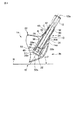
図1は、本発明の好ましい実施形態によるゴルフクラブ10の全体を示す。
FIG. 1 shows an
本実施形態のゴルフクラブ10は、例えば繊維強化樹脂あるいは金属で管状構造に形成したシャフト12の一端すなわち先端に基準水平面Hに対して規定のライ角αおよび図示しないフェース面角(ロフト角)に設定して中空構造のヘッド14を止着し、天然ゴムあるいは合成ゴム等の柔軟性材料や軟質材料で形成したグリップ16を基端に取付けてあり、中空構造のウッド型ゴルフクラブとして形成してある。
The
ここに、ライ角αは、後述するソール部あるいは基準水平面Hに対するシャフト12の中心軸線である軸線12aの角度であり、ヘッド14のソール部18を接地させてゴルフクラブ10をセットしたとき、このソール部18および地面を通る基準水平面Hに対するシャフト12の中心軸線12aの角度を規定するものである。また、フェース面角は、フェース部20の打球面が、基準水平面Hに直交する垂直面との間に形成する角度である。
Here, the lie angle α is an angle of an
本実施形態のヘッド14は、例えば、150〜470cm3 、好ましくは200〜470cm3 で、ヘッド重量が160〜230gに形成され、フェース部に所定のフェース面角が例えば5〜25度で付けられる。このヘッド14には、シャフト12の軸線12aとの取付け角度である所定のライ角αが例えば54度から62度に形成されている。
The
図2に示すように、このゴルフクラブ10のヘッド14は、ステンレス合金、チタンあるいはチタン合金等の金属材から鋳造あるいは鍛造により中空の一体構造に形成されたヘッド本体14aを備える。このヘッド本体14aは、ボールを打球するフェース部20の下縁部および上縁部からバック部側に向けてそれぞれソール部18とクラウン部22とを延設し、これらのソール部18とクラウン部22との間で、フェース部20のトウ部24側縁部からバック部側を介してフェース部20のヒール部26側縁部まで、通常と同様な湾曲した断面形状を有するサイド部が延設されている。なお、フェース部20とクラウン部22とは、その間の稜線で特定することができるが、フェース部20の大部分を形成する面部の曲率半径より小さくなる部位で特定してもよい。フェース部20を区画する他の部位についても同様である。
As shown in FIG. 2, the
このヘッド本体14aは、全体を一体構造に形成し、あるいは、例えばフェース部20に別部材のフェース部材を設ける等、各部を別部材で形成し、これらの複数の部材を互いに接合して形成してもよい。このような複数の部材を接合して形成する場合には、ヘッド本体14aの少なくとも一部に繊維強化樹脂材料を用いることもできる。いずれの場合にも、打球面を形成するフェース部材はステンレス合金、チタンあるいはチタン合金等の金属材料で形成することができ、他の部分すなわちヘッド本体14aよりも高硬度の材質や高強度の材料を用いることが好ましい。
The head
図2から図5に示すように、このヘッド14では、湾曲形状のクラウン部22のヒール部26側からホーゼル部28が突出する。このホーゼル部28は、トウ部24の方向にわずかに傾斜した状態で、クラウン部22からソール部18側に突出させた筒状部30(図3)の頂部で形成されており、この筒状部30に形成したホーゼル孔32に、シャフト12の先端を挿入して接着することにより、シャフト12をヘッド14に止着することができる。この筒状部30の頂部には、ヘッド14の頂部22aすなわち基準水平面Hから最も上方に離隔した部位であるクラウン部22の最上部を通りかつ基準水平面Hに平行な面h(図2)よりも、基準水平面Hからの高さが低い低位置で外部に開口する開口端30aが形成されている。
As shown in FIGS. 2 to 5, in the
この筒状部30のクラウン部22からの突出量すなわちホーゼル孔32が外部に開口する開口端30aの基準水平面Hからの高さ方向位置は、ヘッド14の頂部22aよりも低位置であれば、適宜の位置に調整することができ、筒状部30の端部をクラウン部22の湾曲した外面と同一面内に配置した場合には、ホーゼル部28および開口端30aがクラウン部22から突出することなくヘッド本体14a内に配置された状態となる。このホーゼル孔32を形成する筒状部30は、ヘッド本体14aと同一材料で一体的に形成されている。無論、筒状部30をヘッド本体14aとは別体でかつ異なる材料を用いて形成することも可能である。なお、筒状部30のソール部18側の端部30bは、閉じた状態で示してあるが、この端部30bの全体あるいは一部に開口を形成することで、この筒状部30およびヘッド本体14aを軽量化することができる。
If the projecting amount of the
シャフト12の先端部の外周部にはネック部材34が取り付けられており、シャフト12はこのネック部材34を介して、筒状部30の開口端30aからホーゼル孔32内に装着され、ヘッド本体14aに止着される。このネック部材34の外方端部に、シャフト12に装着したソケット36が配置される。このソケット36は、ネック部材34とシャフト12との間に大きな段差を形成することなく、滑らかに移行する外形形状を形成する。このようなソケット36は、例えば樹脂材料により、シャフト12の軸方向に沿って3〜20mm程度の長さで、ネック部材34側からシャフト12の上方に向けてテーパ状の外形形状に形成することが好ましい。なお、このソケット36は、シャフト12と別体あるいは一体のいずれの構造でもよく、省略することも可能である。
A
図3から図5に示すように、ネック部材34は、全体的に円筒状に形成され、ホーゼル孔32内に挿入される挿入部38と、このホーゼル孔32が開口する筒状部30の開口端30aから外方に突出する外延部40とを有し、シャフト12の先端部が嵌合するシャフト嵌合孔42が、外延部40の頂部側すなわちグリップ16(図1)側の外端44で外方に開口する。シャフト嵌合孔42は、この外端44の開口から、シャフト12の外周面と同軸状の外形形状を有する外延部40内を通って、ホーゼル孔32内に配置される挿入端46に向けて延び、この挿入端46に達する前、すなわちこの挿入端46よりも外延部40側あるいは後述する交点C側で終端する。外延部40がシャフト12と同軸状の外形形状を有することにより、この外延部40を全周に沿ってほぼ均等な肉厚の薄肉構造に形成し、軽量構造とすることができる。
As shown in FIGS. 3 to 5, the
本実施形態では、シャフト嵌合孔42が終端する部位にフランジ状あるいは隔壁状の壁部48を形成してあり、シャフト12の先端に当接させることができる。挿入部38の挿入端46は、シャフト嵌合孔42および壁部48を超えて延び、この壁部48の開口を介してシャフト嵌合孔42に連通する中空部50を、この挿入端46に隣接する部位に形成する。このように、シャフト嵌合孔42を超えて挿入部38を延設することにより、ホーゼル孔32の内周面と挿入部38の外周面との間に、接合強度を維持するために充分な接合面を確保してヘッド本体14aに対するネック部材34の固定強度を向上させると共に、その中空構造により、ネック部材34の軽量化を図ることができる。
In the present embodiment, a flange-like or partition-
このシャフト嵌合孔42の終端部あるいは壁部48から挿入端46までの軸方向長さにより、シャフト12とシャフト嵌合孔42の内周面との接合面積に対して、ネック部材34の挿入部38とホーゼル孔32の内周面との接合面積の比率を任意に調整することができる。この接合面積の比率は例えばほぼ等しくなるように設定してもよい。シャフト12およびヘッド本体14aに対するネック部材34の接合面積の比率がほぼ等しい場合には、ネック部材34の形状および重量を必要かつ充分な大きさに最適化することができる。また、外周面が小径に形成されるシャフト12の先端部とネック部材34との間にも充分な大きさの接合面積を確保することができ、これにより、ヘッド14に対するシャフト12の必要かつ充分な大きさの取付強度を確保しつつ、ヘッド本体14aの筒状部30およびネック部材34を含む取付部を軽量構造とすることができる。
The insertion of the
本実施形態では、ネック部材34の挿入端46と筒状部30の閉端部30bとの間に空間部51を形成してあるが、筒状部30がヘッド本体14a内で延びる長さを挿入部38の長さに対応させ、空間部51を省略することも可能である。このようなヘッド本体14a内に形成する中空部50、あるいは挿入部38の挿入端46と筒状部30の端部30bとの間の空間部51には、適宜の重量部材を配置し、ヘッド14の重量バランスを調整することも可能である。
In the present embodiment, the
この挿入部38は、ホーゼル孔32に対応した円筒状の外周面を有し、ホーゼル孔32内に装着したときに、挿入部38の外周面の中心軸線38aが、ホーゼル孔32の中心軸線32aと同軸状に配置される。一方、シャフト嵌合孔42はシャフト12の先端部に嵌合したときにシャフト12の軸線12aと同軸状に配置される中心軸線42aを有し、この中心軸線42aは挿入部38の中心軸線38aに対して傾斜配置され、これらの中心軸線38a,42aの交点Cが挿入部38と外延部40との間の境界部に配置される。
The
したがって、挿入部38は、シャフト嵌合孔42の終端部すなわち壁部48の近部で、周方向に沿って肉厚が大きく変化し、径方向に対向した部位に最小肉厚部39aと最大肉厚部39bとが形成される。この最小肉厚部39aと最大肉厚部39bとが形成されるシャフト嵌合孔42の終端部あるいは壁部48を交点Cに近接させるほど、ホーゼル孔32の中心軸線32aに対する挿入部38の外周部の中心軸線38aの傾斜角度を大きくすることができる。すなわち、外径が同じ場合、挿入部38内のシャフト嵌合孔42の長さが短いほど、ホーゼル孔32の中心軸線32aに対する中心軸線38aの傾斜角度を大きくすることができ、これにより、ホーゼル孔32内のネック部材34の位置を回転することで、広範囲かつ高精度でシャフト12の傾きを調整することができる。
Therefore, the thickness of the
本実施形態では、この交点Cが配置される境界部を含む外周部領域には、周方向に沿う外周フランジ状の段差部52が一体に形成されている。この段差部52はネック部材34の外端44側に縮径するテーパ状の外面を有し、挿入端46側には、挿入部38の外周面に対して垂直な面内に配置される環状面54が形成されている。この環状面54は、筒状部30の開口端30aが開口する開口端面31との間に、環状溝状の凹陥部Rが挿入部38の外周を囲む状態に形成する。この環状面54が挿入部38の外周面に対して垂直な面内に配置されることにより、挿入部38がホーゼル孔32の中心軸線32aを中心として回転しても、環状面54と開口端面30aとの間に形成される凹陥部Rの幅w(図6参照)すなわちネック部材34の長手方向あるいは挿入部38の中心軸線38aに沿う寸法が全周にわたって一定に保持される。
In the present embodiment, an outer peripheral flange-shaped stepped
この凹陥部Rの幅wである軸方向寸法は、後述するように、ヘッド14からシャフト12を分解する際、例えば万力を使用するときに、引抜き用の冶具である抜きコマJ(図6参照)を装着できるものであればよく、例えば3mm〜10mm程度の幅寸法すなわちネック部材34の長手方向寸法を有することが好ましい。なお、この凹陥部Rは図示のように、全周にわたって形成することに代え、例えば径方向に対向する2箇所にのみ設けてもよい。この場合には、各凹陥部Rは、段差部52に形成してもよい。このように凹陥部Rが周方向に沿って非連続に形成される場合には、後述する保護部材Gでこれらの凹陥部Rを囲んでもよい。なお、段差部52に凹陥部Rを形成する場合には、段差部52の環状面54がヘッドの開口端面31に当接する。
As will be described later, the axial dimension, which is the width w of the concave portion R, is a punching piece J (FIG. 6) that is a jig for drawing when the
更に、交点Cがネック部材34の挿入部38と外延部40との間の境界部に配置されることにより、外延部40およびシャフト12がホーゼル28から直線状に突出した状態となり、先端部分が屈曲した状態を外部から見ることはできない。したがって、アドレス時に違和感を与えることがない。
Furthermore, the intersection C is arranged at the boundary between the
このような違和感を与えないネック部材34とするためには、交点Cが凹陥部Rの幅方向中心位置から、凹陥部Rの幅wの寸法の距離だけ、外延部40の外端44側と挿入部38の挿入端46側との長手方向の両方向に変位した2つの位置で区画される範囲内に位置するものであればよい。すなわち、交点Cを、{(凹陥部Rの軸方向中心位置)±(凹陥部Rの幅w)}で区画される範囲(凹陥部Rの幅wの2倍の範囲)内に配置することにより、挿入部38と外延部40との間の外面形状の変化が保護部材Gを嵌合した凹陥部Rおよび段差部52の領域で緩和され、外部から認識されず、打球する際の違和感が生じない。
In order to obtain the
本実施形態の凹陥部Rは、保護部材Gにより外部から保護されている。この保護部材Gは、段差部52とヘッド本体14aとの間を段差のない連続面で連結して外観を向上させると共に、特にこの凹陥部Rを形成する環状面54および開口端面31を保護することができるものであれば適宜の形状に形成してもよい。この保護部材Gは、合成樹脂の他にも、ゴム、合成コルクあるいは木材等の天然材料で形成することができる。例えばゴルフクラブ10の修理、あるいはフェース面角やライ角αの調整のためにシャフト12を分解する際に、この保護部材Gの取外しを容易にするために、特殊な工具を用いることなく、例えばカッターナイフ等の簡単な工具でも切除できる材料を用いることが好ましい。
The recessed portion R of the present embodiment is protected from the outside by a protective member G. The protective member G improves the appearance by connecting the stepped
この保護部材Gは、一体構造以外にも、例えば断面をC字状に形成した複数の保護片(図示しない)を組合せて形成してもよく、特に簡単に形成する場合には、ゴム製のOリング(図示しない)で形成することもできる。いずれの場合も、保護部材Gの外面に着色あるいは模様を形成し、ゴルフクラブ10の外観にアクセントを付加するものであってもよい。
The protective member G may be formed by combining, for example, a plurality of protective pieces (not shown) having a C-shaped cross section in addition to the integral structure. It can also be formed with an O-ring (not shown). In either case, coloring or a pattern may be formed on the outer surface of the protective member G to add an accent to the appearance of the
このような、ゴルフクラブ10は、ゴルファーの好みに応じて、ヘッド本体14aに対するシャフト12の軸線12aの位置を変更することができる。例えば図3に実線で示すように、挿入部38の最小肉厚部39aをヒール部26側に配置したライ角α1の状態から、ホーゼル孔32の中心軸線32aを中心として、ネック部材34およびシャフト12を回転すると、ネック部材34の外延部40およびシャフト12が交点Cを頂点とする円錐形状を形成するように揺動し、図4に実線で示すように、最小肉厚部39aがクラウン部22側に配置されてライ角α2を形成する位置に配置することができる。図には、ライ角αについてのみ示してあるが、フェース面角やフェース面の相対位置等を調整することが可能なことは明らかである。例えばフェース面角(いわゆるロフト角)は、最小肉厚部39aがフェース部20側に配置されると小さくなり、逆にバック部側に配置されると大きくなる。
Such a
実際のゴルフクラブ10に適用する場合には、ネック部材34を、アルミニウム、アルミニウム合金、マグネシウム合金、チタン合金、純チタン等の金属の他、ポリカーボネート(PC)、ABS等の樹脂、繊維強化樹脂で形成することが可能である。このネック部材34が接着剤を用いてヘッド本体14aに固定されるゴルフクラブについては、加熱により接着部を分離してシャフト12の交換あるいは調整を容易にするために、熱に強く、リサイクル性に優れた軽量金属を用いることが好ましい。また、アルマイト、メッキ、イオンプレーティング等、塗装以外の方法による表面処理を施した場合には、シャフトの交換あるいは調整等のリシャフトをしても、加熱処理の際に外観を損なうことがない。
When applied to an
通常、ゴルフクラブのシャフト12の外径が8.4mm〜11mmであり、挿入部38内の最小肉厚部39aの肉厚を、筒状部30の強度やネック部材34の成形上の限界から0.3mmとしたときに、挿入部38の外径は10.0mm〜13.0mmの範囲に形成するのが好ましい。また、シャフト嵌合孔42の軸方向長さは、25mm〜60mmに形成することにより、シャフト12との間に好適な接着あるいは接合面積を確保することができる。このシャフト嵌合孔42の軸方向長さがこの範囲よりも短すぎると、接着力が不足し、長すぎると重量が増大することになる。一方、ホーゼル孔32内に接合される挿入部38は、シャフト12の外径よりも大径であるため、挿入部38の軸方向長さは、シャフト嵌合孔42の軸方向長さよりも短く形成することができ、例えば20mm〜40mmで、特に23mm〜30mm程度に形成するのが好ましい。
Usually, the outer diameter of the
また、挿入部38内におけるシャフト嵌合孔42の長さすなわち交点Cとシャフト嵌合孔42の終端である壁部48との間の距離が短い程、上述のようにホーゼル孔32の中心軸線32aに対する挿入部38の外周部の中心軸線38aの傾斜角度を大きくすることが可能であるが、充分な接着面積を形成するために12mmから30mm程度に形成することが好ましい。このシャフト嵌合孔42の終端と挿入部38の挿入端46との間に形成される中空部50の内径は、シャフト嵌合孔42の内径よりも大径に形成することにより、挿入部38と筒状部30との間の接着剤を介在させる接着面積を確保しつつ、ネック部材34を軽量化することができる。
Further, as the length of the shaft
一方、外延部40は、シャフト12の外形に沿うものであれば、適宜の外径に形成することが可能であるが、挿入部38の外径よりも大きく、かつ、挿入部38の外径の1.4倍以下であることが好ましい。この外延部40の外径を挿入部38の外径以下の大きさに形成すると、交点Cの付近に応力が集中し、破損する可能性があり、挿入部38の外径の1.4倍よりも大きく形成する場合には、この外延部40の肉厚が増大し、重量化するためである。
On the other hand, the outer extending
図5の(B)は、外延部40の外径を挿入部38の外径よりも大きく形成し、環状面54をこの外延部40と挿入部38との間の外周面間の段差面で形成した変形例によるネック部材34Aを示す。このネック部材34Aは、段差部52が外延部40と共に連続した円筒状の断面形状を形成する。
In FIG. 5B, the outer diameter of the outer extending
このようなネック部材34は、ホーゼル孔32の中心軸線32aに対する挿入部38の外周部の中心軸線38aの傾斜角度を変更することにより、ライ角やフェース面角を調整する範囲を変更することができる。例えば、中心軸線32aに対する中心軸線38aの傾斜角度の異なる複数のネック部材34を準備しておくことにより、ゴルファーの好みに応じて様々な範囲で調整することができる。例えば、この交点Cの位置を長手方向に沿って移動すると、ホーゼル孔32の中心軸線32aすなわち挿入部38の中心軸線38aに対するシャフト嵌合孔42の中心軸線42aの角度が変更し、これにより、ヘッド14に対するシャフト12の傾きの調整可能な範囲を、ネック部材34毎に変更することができる。
Such a
図6および図7は、例えばゴルフクラブ10の修理、あるいはフェース面角やライ角αの再調整のためにシャフト12を分解する手順の例を示す。
6 and 7 show an example of a procedure for disassembling the
まず、ネック部材34とヘッド本体14aとの間の凹陥部R内に配置された保護部材Gを、必要な場合にはカッターナイフ等で切除し、凹陥部Rを外部に露出する。
First, the protective member G disposed in the recessed portion R between the
万力等の引抜き装置に用いる冶具の引抜きコマJを凹陥部Rに差込み、ヘッド本体14aの開口端面31に当接させる。一方、ネック部材34の外延部40にチャックKを固定し、引抜きコマJで固定されたヘッド本体14aに対し、チャックKを固定したネック部材34をシャフト12と共に、ホーゼル孔32の中心軸線32aに沿ってシャフトのグリップ16(図1)側に引抜く。このネック部材34を引抜く際あるいはその直前に、ネック部材34とヘッド本体14aとの接着部分を、ネック部材34側、ヘッド本体14a側から加熱することにより、接着剤を軟化させることができる。
An extraction piece J of a jig used for an extraction device such as a vise is inserted into the recessed portion R and brought into contact with the opening
同様に、ネック部材34とシャフト12とに引抜き装置を取付け、ネック部材34を加熱して、シャフト嵌合孔32の内面の接着剤を軟化させ、シャフト12をネック部材34から引抜き、分解する。この後、ソケット36をカッターナイフ等で切除する。このソケット36は、保護部材Gの除去と同時、または、シャフト12をネック部材34から引抜き、分解する前に行ってもよい。このようにシャフト12をネック部材34から引抜く際は、例えばネック部材34の外端44がシャフト12の外周面との間に段差を形成するため、この段差部分に引抜きコマJを差込み、ネック部材34からシャフト12を引抜き、分解することができる。
Similarly, a pulling device is attached to the
図7に示すように、ヘッド本体14aとネック部材34とシャフト12とに分解した後、古い接着剤を取り除き、上述のように、ネック部材34を調整範囲の異なるものと交換し、あるいはヘッド本体14aに対するシャフト12の軸線12aの位置を再調整して組立てる。ソケット36および保護部材Gは、組立ての直前あるいは組立後に新しいものを取付ける。また、硬さやキックポイントの異なるシャフトを取付けたり、場合によっては、ヘッド14を別の仕様(例えば、重心位置の深いもの等)のものに取り替えることもできる。
As shown in FIG. 7, after the head
このようにヘッド本体14aとの間に凹陥部Rを形成するネック部材34の好ましい例として、シャフト嵌合孔42の内径をシャフト12の外径に対応させて9.0mmとしたときに、挿入部38および外延部40の外径をそれぞれ11.0mm、12.0mm、中空部50の内径を9.6mm、挿入部38および外延部40のそれぞれの軸方向長さは25mmおよび23mm、壁部48と環状面54との間の軸方向長さを16mm、最小肉厚部39aの肉厚は0.3に形成し、シャフト嵌合孔42の中心軸線42aと挿入部38の外周部の中心軸線38aとの間の角度は2.51に形成したアルミ合金(AA6061)製のネック部材について、50m/sの速度で打球するロボットを用いて耐久テストをしたところ、3000発の打球でも損傷が認められなかった。
As a preferred example of the
このゴルフクラブ10によると、保護部材Gを凹陥部Rから取外し、ネック部材34の外延部40に形成された段差部52とヘッド本体14aとの間の凹陥部Rを露出し、この凹陥部Rに引抜き具Jを係止することにより、ネック部材34およびヘッド14に、ホーゼル孔32の中心軸線32aに沿う軸線方向に沿う力を作用させ、ネック部材34およびヘッド本体14aに損傷を与えることなく、容易に分解することができ、これにより、ヘッド14、ネック部材34およびシャフト12の分解前の精度を維持でき、必要な角度で再度組立てることができる。
According to this
また、凹陥部Rの幅は狭く、しかも保護部材Gが装着されていることにより、凹陥部Rを形成する段差部52の環状面54およびヘッド本体14aの開口端面31が、通常の打球時に傷つくのを防止することができる。また、分解する際は、極めて簡単に除去できるため、シャフト12の交換あるいは調整等のリシャフトの作業工程が増えることもない。
Further, since the width of the recessed portion R is narrow and the protective member G is attached, the
また、広範囲にわたってシャフト12の傾きを調整して再組立した後も、アドレス時に違和感を与えることのない状態とし、ネック部材34の外延部40により、シャフト12とネック部材34との接合面積が確保され、ヘッド本体14aとシャフト12との取付強度を確保することができ、ヘッド14に対するシャフト12の取付部の軽量構造を維持することができる
特に、上述のゴルフクラブ10では、シャフト嵌合孔42の中心軸線42aと挿入部38の外周面の中心軸線38aとの交点Cが挿入部38と外延部40との間の境界部に配置されることにより、ヘッド14に対してネック部材34を僅かに回転するだけで効率よく、広範囲にわたってシャフト12の傾きを調整することができる。また、ネック部材34が挿入部38を介してヘッド本体14aのホーゼル孔32に取付けられ、外延部40から挿入部38内に延びるシャフト嵌合孔42にシャフト12の先端が取付けられることにより、ネック部材34を介するヘッド14とシャフト12との取付け強度が確保され、このネック部材34を軽量構造とすることができる。更に、ホーゼル孔32の外部に屈曲部が形成されないため、ヘッド14に対するシャフト12の傾斜を大きく変えた場合であっても、ヘッド14の外部に屈曲部が形成されず、違和感なくゴルフクラブ10を構えることができる。
In addition, after reassembling the
以上、本発明の好ましい実施形態について説明してきたが、本発明は、上述の実施形態に限定されるものではなく、様々に変更することが可能である。例えば、上述の実施形態のように、ネック部材34をシャフト12と別部材で形成することに代え、このネック部材34をシャフト12の先端に一体的に形成してもよい。この場合には挿入部38の最小薄肉部39aの厚さを考慮する必要がなく、更に軽量化することができる。また、ヘッド本体14aとシャフト12との間にネック部材34を配置するものであれば、上述のように基準水平面Hからの高さが低い低位置で外部に開口する開口端30aが形成されるものに限らず、あらゆるゴルフクラブに用いることができる。
The preferred embodiments of the present invention have been described above. However, the present invention is not limited to the above-described embodiments, and various modifications can be made. For example, instead of forming the
10…ゴルフクラブ、12…シャフト、14…ヘッド、14a…ヘッド本体、30a…開口端、32…ホーゼル孔、34…ネック部材、38…挿入部、40…外延部、42…シャフト嵌合孔、52…段差部、R…凹陥部。
DESCRIPTION OF
Claims (4)
前記ネック部材は、ヘッドのホーゼル孔内に挿入される挿入部と、このホーゼル孔の開口端から外方に突出しかつシャフトの一端が挿通されるシャフト嵌合孔が外端で開口する外延部とを有し、前記挿入部をホーゼル孔に挿入したときに、このホーゼル孔の開口端との間に凹陥部を形成する段差部を前記外延部の外周部に形成したことを特徴とするゴルフクラブ。 A golf club in which one end of a shaft is fixed to a hosel hole formed in a head via a neck member,
The neck member includes an insertion portion that is inserted into the hosel hole of the head, and an extension portion that protrudes outward from the opening end of the hosel hole and has a shaft fitting hole that is inserted through one end of the shaft at the outer end. A golf club characterized in that, when the insertion portion is inserted into a hosel hole, a stepped portion is formed on the outer peripheral portion of the extension portion to form a recessed portion between the open end of the hosel hole. .
Priority Applications (1)
| Application Number | Priority Date | Filing Date | Title |
|---|---|---|---|
| JP2007173223A JP2009011366A (en) | 2007-06-29 | 2007-06-29 | Golf club |
Applications Claiming Priority (1)
| Application Number | Priority Date | Filing Date | Title |
|---|---|---|---|
| JP2007173223A JP2009011366A (en) | 2007-06-29 | 2007-06-29 | Golf club |
Publications (1)
| Publication Number | Publication Date |
|---|---|
| JP2009011366A true JP2009011366A (en) | 2009-01-22 |
Family
ID=40353024
Family Applications (1)
| Application Number | Title | Priority Date | Filing Date |
|---|---|---|---|
| JP2007173223A Pending JP2009011366A (en) | 2007-06-29 | 2007-06-29 | Golf club |
Country Status (1)
| Country | Link |
|---|---|
| JP (1) | JP2009011366A (en) |
Cited By (7)
| Publication number | Priority date | Publication date | Assignee | Title |
|---|---|---|---|---|
| JP2013517895A (en) * | 2010-01-27 | 2013-05-20 | ナイキ インターナショナル リミテッド | Golf club assembly and golf club having an aerodynamic hosel |
| JP2013192667A (en) * | 2012-03-19 | 2013-09-30 | Globeride Inc | Golf club and golf club head |
| US9314677B2 (en) | 2009-05-13 | 2016-04-19 | Nike, Inc. | Golf club assembly and golf club with aerodynamic features |
| US9370696B2 (en) | 2009-05-13 | 2016-06-21 | Nike, Inc | Golf club assembly and golf club with aerodynamic features |
| US9375617B2 (en) | 2009-05-13 | 2016-06-28 | Nike, Inc | Golf club assembly and golf club with aerodynamic features |
| US9526954B2 (en) | 2012-05-31 | 2016-12-27 | Nike, Inc. | Golf club assembly and golf club with aerodynamic features |
| US9956459B2 (en) | 2009-05-13 | 2018-05-01 | Nike, Inc. | Golf club assembly and golf club with aerodynamic features |
-
2007
- 2007-06-29 JP JP2007173223A patent/JP2009011366A/en active Pending
Cited By (8)
| Publication number | Priority date | Publication date | Assignee | Title |
|---|---|---|---|---|
| US9314677B2 (en) | 2009-05-13 | 2016-04-19 | Nike, Inc. | Golf club assembly and golf club with aerodynamic features |
| US9370696B2 (en) | 2009-05-13 | 2016-06-21 | Nike, Inc | Golf club assembly and golf club with aerodynamic features |
| US9375617B2 (en) | 2009-05-13 | 2016-06-28 | Nike, Inc | Golf club assembly and golf club with aerodynamic features |
| US9802085B2 (en) | 2009-05-13 | 2017-10-31 | Nike, Inc. | Golf club assembly and golf club with aerodynamic features |
| US9956459B2 (en) | 2009-05-13 | 2018-05-01 | Nike, Inc. | Golf club assembly and golf club with aerodynamic features |
| JP2013517895A (en) * | 2010-01-27 | 2013-05-20 | ナイキ インターナショナル リミテッド | Golf club assembly and golf club having an aerodynamic hosel |
| JP2013192667A (en) * | 2012-03-19 | 2013-09-30 | Globeride Inc | Golf club and golf club head |
| US9526954B2 (en) | 2012-05-31 | 2016-12-27 | Nike, Inc. | Golf club assembly and golf club with aerodynamic features |
Similar Documents
| Publication | Publication Date | Title |
|---|---|---|
| JP5736985B2 (en) | Manufacturing method of golf club head | |
| US8192299B2 (en) | Golf club and method for adjusting properties thereof | |
| JP2009011366A (en) | Golf club | |
| US6305063B1 (en) | Method of manufacturing a golf club head | |
| US7140977B2 (en) | Golf club head | |
| US7976401B2 (en) | Golf club and shaft replacing method | |
| US20080261716A1 (en) | Golf Club | |
| JPH03176084A (en) | Device for fixing golf club head to handle | |
| JP2006042951A (en) | Golf club | |
| JP2006320493A (en) | Golf club head | |
| JP6719761B2 (en) | putter | |
| JP4365676B2 (en) | Wood type golf club head | |
| JP4808562B2 (en) | Golf club | |
| JP5099679B2 (en) | Golf club | |
| JP2013027417A (en) | Golf club and method for adjusting characteristic of the same | |
| JP5447141B2 (en) | Golf club | |
| JP6484119B2 (en) | Golf club head | |
| JP4709111B2 (en) | Golf club | |
| US6890266B2 (en) | Methods and apparatus for a metal wood-type golf club | |
| JP2020191938A (en) | Golf club head | |
| JP2009066122A (en) | Golf club head and shaft attachment / detachment system | |
| JP6175762B2 (en) | Golf club and method for adjusting characteristics thereof | |
| JP2007222304A (en) | Golf club | |
| JP2015029833A (en) | Golf club head | |
| JP4654518B2 (en) | Golf club head |