JP2008547175A - Optical waveguide with optical deflection region - Google Patents
Optical waveguide with optical deflection region Download PDFInfo
- Publication number
- JP2008547175A JP2008547175A JP2008518434A JP2008518434A JP2008547175A JP 2008547175 A JP2008547175 A JP 2008547175A JP 2008518434 A JP2008518434 A JP 2008518434A JP 2008518434 A JP2008518434 A JP 2008518434A JP 2008547175 A JP2008547175 A JP 2008547175A
- Authority
- JP
- Japan
- Prior art keywords
- optical waveguide
- input window
- front surface
- optical
- waveguide
- Prior art date
- Legal status (The legal status is an assumption and is not a legal conclusion. Google has not performed a legal analysis and makes no representation as to the accuracy of the status listed.)
- Granted
Links
Images


Classifications
-
- G—PHYSICS
- G02—OPTICS
- G02B—OPTICAL ELEMENTS, SYSTEMS OR APPARATUS
- G02B6/00—Light guides; Structural details of arrangements comprising light guides and other optical elements, e.g. couplings
- G02B6/0001—Light guides; Structural details of arrangements comprising light guides and other optical elements, e.g. couplings specially adapted for lighting devices or systems
- G02B6/0011—Light guides; Structural details of arrangements comprising light guides and other optical elements, e.g. couplings specially adapted for lighting devices or systems the light guides being planar or of plate-like form
- G02B6/0013—Means for improving the coupling-in of light from the light source into the light guide
- G02B6/0015—Means for improving the coupling-in of light from the light source into the light guide provided on the surface of the light guide or in the bulk of it
- G02B6/0018—Redirecting means on the surface of the light guide
-
- F—MECHANICAL ENGINEERING; LIGHTING; HEATING; WEAPONS; BLASTING
- F21—LIGHTING
- F21S—NON-PORTABLE LIGHTING DEVICES; SYSTEMS THEREOF; VEHICLE LIGHTING DEVICES SPECIALLY ADAPTED FOR VEHICLE EXTERIORS
- F21S43/00—Signalling devices specially adapted for vehicle exteriors, e.g. brake lamps, direction indicator lights or reversing lights
- F21S43/20—Signalling devices specially adapted for vehicle exteriors, e.g. brake lamps, direction indicator lights or reversing lights characterised by refractors, transparent cover plates, light guides or filters
- F21S43/235—Light guides
- F21S43/236—Light guides characterised by the shape of the light guide
- F21S43/237—Light guides characterised by the shape of the light guide rod-shaped
-
- F—MECHANICAL ENGINEERING; LIGHTING; HEATING; WEAPONS; BLASTING
- F21—LIGHTING
- F21S—NON-PORTABLE LIGHTING DEVICES; SYSTEMS THEREOF; VEHICLE LIGHTING DEVICES SPECIALLY ADAPTED FOR VEHICLE EXTERIORS
- F21S43/00—Signalling devices specially adapted for vehicle exteriors, e.g. brake lamps, direction indicator lights or reversing lights
- F21S43/20—Signalling devices specially adapted for vehicle exteriors, e.g. brake lamps, direction indicator lights or reversing lights characterised by refractors, transparent cover plates, light guides or filters
- F21S43/235—Light guides
- F21S43/236—Light guides characterised by the shape of the light guide
- F21S43/241—Light guides characterised by the shape of the light guide of complex shape
-
- F—MECHANICAL ENGINEERING; LIGHTING; HEATING; WEAPONS; BLASTING
- F21—LIGHTING
- F21S—NON-PORTABLE LIGHTING DEVICES; SYSTEMS THEREOF; VEHICLE LIGHTING DEVICES SPECIALLY ADAPTED FOR VEHICLE EXTERIORS
- F21S43/00—Signalling devices specially adapted for vehicle exteriors, e.g. brake lamps, direction indicator lights or reversing lights
- F21S43/20—Signalling devices specially adapted for vehicle exteriors, e.g. brake lamps, direction indicator lights or reversing lights characterised by refractors, transparent cover plates, light guides or filters
- F21S43/235—Light guides
- F21S43/242—Light guides characterised by the emission area
- F21S43/245—Light guides characterised by the emission area emitting light from one or more of its major surfaces
-
- F—MECHANICAL ENGINEERING; LIGHTING; HEATING; WEAPONS; BLASTING
- F21—LIGHTING
- F21S—NON-PORTABLE LIGHTING DEVICES; SYSTEMS THEREOF; VEHICLE LIGHTING DEVICES SPECIALLY ADAPTED FOR VEHICLE EXTERIORS
- F21S43/00—Signalling devices specially adapted for vehicle exteriors, e.g. brake lamps, direction indicator lights or reversing lights
- F21S43/20—Signalling devices specially adapted for vehicle exteriors, e.g. brake lamps, direction indicator lights or reversing lights characterised by refractors, transparent cover plates, light guides or filters
- F21S43/235—Light guides
- F21S43/249—Light guides with two or more light sources being coupled into the light guide
-
- G—PHYSICS
- G02—OPTICS
- G02B—OPTICAL ELEMENTS, SYSTEMS OR APPARATUS
- G02B6/00—Light guides; Structural details of arrangements comprising light guides and other optical elements, e.g. couplings
- G02B6/0001—Light guides; Structural details of arrangements comprising light guides and other optical elements, e.g. couplings specially adapted for lighting devices or systems
- G02B6/0011—Light guides; Structural details of arrangements comprising light guides and other optical elements, e.g. couplings specially adapted for lighting devices or systems the light guides being planar or of plate-like form
- G02B6/0033—Means for improving the coupling-out of light from the light guide
- G02B6/0035—Means for improving the coupling-out of light from the light guide provided on the surface of the light guide or in the bulk of it
- G02B6/0038—Linear indentations or grooves, e.g. arc-shaped grooves or meandering grooves, extending over the full length or width of the light guide
-
- F—MECHANICAL ENGINEERING; LIGHTING; HEATING; WEAPONS; BLASTING
- F21—LIGHTING
- F21K—NON-ELECTRIC LIGHT SOURCES USING LUMINESCENCE; LIGHT SOURCES USING ELECTROCHEMILUMINESCENCE; LIGHT SOURCES USING CHARGES OF COMBUSTIBLE MATERIAL; LIGHT SOURCES USING SEMICONDUCTOR DEVICES AS LIGHT-GENERATING ELEMENTS; LIGHT SOURCES NOT OTHERWISE PROVIDED FOR
- F21K9/00—Light sources using semiconductor devices as light-generating elements, e.g. using light-emitting diodes [LED] or lasers
- F21K9/60—Optical arrangements integrated in the light source, e.g. for improving the colour rendering index or the light extraction
- F21K9/61—Optical arrangements integrated in the light source, e.g. for improving the colour rendering index or the light extraction using light guides
-
- F—MECHANICAL ENGINEERING; LIGHTING; HEATING; WEAPONS; BLASTING
- F21—LIGHTING
- F21Y—INDEXING SCHEME ASSOCIATED WITH SUBCLASSES F21K, F21L, F21S and F21V, RELATING TO THE FORM OR THE KIND OF THE LIGHT SOURCES OR OF THE COLOUR OF THE LIGHT EMITTED
- F21Y2115/00—Light-generating elements of semiconductor light sources
- F21Y2115/10—Light-emitting diodes [LED]
Landscapes
- Physics & Mathematics (AREA)
- Engineering & Computer Science (AREA)
- General Engineering & Computer Science (AREA)
- General Physics & Mathematics (AREA)
- Optics & Photonics (AREA)
- Non-Portable Lighting Devices Or Systems Thereof (AREA)
- Optical Couplings Of Light Guides (AREA)
- Light Guides In General And Applications Therefor (AREA)
- Endoscopes (AREA)
Abstract
本発明は入力窓、遠端、前面および後面を備えた剛性の光伝送体を有する光導波体に関する。本発明によれば、光伝送体は滑らかな外面としての前面と透明かつ固体の内部と光を内部へ入力するための入力窓とを有しており、該入力窓は中心軸線に対してほぼ横断方向に延在しており、光伝送体は、前面から後面までの距離としてのほぼ一定の厚さを有しており、かつ、入力窓から60゜〜120゜の弧部を介して出力領域をなす延長部を経て遠端まで延在しており、少なくとも出力領域の後面に前面へ向かって光を偏向する複数の反射段が設けられている。 The present invention relates to an optical waveguide having a rigid optical transmission body having an input window, a far end, a front surface, and a rear surface. According to the present invention, the optical transmission body has a front surface as a smooth outer surface, a transparent and solid interior, and an input window for inputting light into the interior. The optical transmission body extends in the transverse direction, has an almost constant thickness as a distance from the front surface to the rear surface, and outputs from the input window through an arc portion of 60 ° to 120 °. It extends to the far end through an extension portion forming a region, and a plurality of reflection stages for deflecting light toward the front surface are provided at least on the rear surface of the output region.
Description
関連出願に対するクロスリファレンス
本願は2005年6月23日付の米国出願第60/693254号"REPLACEABLE VEHICLE LAMP WITH LED LIGHT SOURCES"および2005年6月24日付の米国出願第60/693999号"DIRECT OPTICAL LIGHT GUIDE"に関連しており、これらの出願の優先権を主張する。
CROSS REFERENCE TO RELATED APPLICATIONS This application is based on US Application No. 60/692544 “REPLACEABLE VEHICLE LAMP WITH LED LIGHT SOURCES” dated June 23, 2005 and US Application No. 60/69999, “DIRECT OPTICAL LIGHT GUIDE” dated June 24, 2005. In relation to and claim priority of these applications.
発明の属する技術分野
本発明は光導波体に関する。より詳細に云えば、本発明はLED光源を有する車両ランプアセンブリ用の光導波体に関する。
TECHNICAL FIELD The present invention relates to an optical waveguide. More particularly, the present invention relates to an optical waveguide for a vehicle lamp assembly having an LED light source.
背景技術
工業分野では光源をできるだけ小さくすることは必須であるとされている。光源を小さくすることにより材料コストが節約され、光学的なイメージング能も向上する。しかし一方では大きな領域を照明しなければならないという逆の要求も存在する。特に車両照明では、当該の車両の存在を表すために車両の表面に大きな視覚画像が必要である。後者の要求は過去においては大きな白熱灯およびリフレクタ装置を用いることによって満たされた。ついでソリッドステート照明の登場により光源のサイズを大幅に低減することに重点が置かれてきたが、ビーム状照明を大きな領域へ拡大して車両を良好に照明しようとする要求はいまだに存在する。リフレクタを必要としない照明システム、さらには交換可能な光源を利用できる照明システムが提供されることが望まれている。
Background Art In the industrial field, it is essential to make the light source as small as possible. Smaller light sources save material costs and improve optical imaging capabilities. On the other hand, however, there is a reverse requirement that a large area must be illuminated. In particular, in vehicle lighting, a large visual image is required on the surface of the vehicle in order to indicate the presence of the vehicle. The latter requirement has been met in the past by using large incandescent lamps and reflector devices. Then, with the advent of solid-state lighting, emphasis has been placed on significantly reducing the size of the light source, but there is still a demand to illuminate the vehicle well by expanding the beam-like lighting to a large area. It would be desirable to provide an illumination system that does not require a reflector and that can utilize a replaceable light source.
発明の概要
上述した課題は、入力窓、遠端、前面および後面を備えたほぼ剛性の光伝送体を有する光導波体において、光伝送体はほぼ滑らかな外面としての前面とほぼ透明かつ固体の内部と光を内部へ入力するための入力窓とを有しており、この入力窓は中心軸線に対してほぼ横断方向に延在しており、光伝送体は、ほぼ一定の厚さすなわちほぼ一定の前面から後面までの距離を有しており、かつ、入力窓から60゜〜120゜の弧部を介して出力領域をなす延長部を経て遠端まで延在しており、少なくとも出力領域の後面に前面へ向かって捕捉光(intercepted light)を偏向する複数の反射段が設けられている構成により解決される。
SUMMARY OF THE INVENTION The problem described above is that in an optical waveguide having a substantially rigid optical transmission body with an input window, a far end, a front surface and a rear surface, the optical transmission body is substantially transparent and solid with the front surface as a substantially smooth outer surface. And an input window for inputting light into the interior, the input window extending in a direction substantially transverse to the central axis, and the optical transmission body having a substantially constant thickness, i.e., approximately It has a certain distance from the front surface to the rear surface, and extends from the input window to the far end through an extension portion forming an output region through an arc portion of 60 ° to 120 °, and at least the output region This is solved by a configuration in which a plurality of reflection stages for deflecting intercepted light toward the front surface are provided on the rear surface.
本発明の光導波体は持続的に車両に搭載され、交換可能な光源とともに利用することができる。本発明の光導波体を用いれば、装飾性または実用性に関する目的に応じてさまざまな光出力の設計が可能となる。 The optical waveguide of the present invention is continuously mounted on a vehicle and can be used with a replaceable light source. If the optical waveguide of the present invention is used, various light output designs can be made according to the purpose of decoration or practicality.
図面の簡単な説明
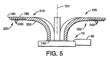
図1には本発明で用いられる第1の光源の平面図が示されている。図2には本発明で用いられる第2の光源の平面図が示されている。図3には図1の3−3線での断面図が示されている。図4には本発明の光導波体の第1の実施例の平面図が示されている。図5には図4の5−5線での断面図が示されている。図6には本発明の光導波体の第2の実施例の平面図が示されている。図7には図6の7−7線での断面図が示されている。図8には本発明の光導波体の第3の実施例の平面図が示されている。図9には図8の9−9線での断面図が示されている。図10には本発明の光導波体の光偏向領域の部分斜視図が示されている。
BRIEF DESCRIPTION OF THE DRAWINGS FIG. 1 is a plan view of a first light source used in the present invention. FIG. 2 shows a plan view of the second light source used in the present invention. FIG. 3 is a sectional view taken along line 3-3 in FIG. FIG. 4 shows a plan view of the first embodiment of the optical waveguide of the present invention. FIG. 5 is a sectional view taken along line 5-5 of FIG. FIG. 6 shows a plan view of a second embodiment of the optical waveguide according to the present invention. FIG. 7 is a sectional view taken along line 7-7 in FIG. FIG. 8 is a plan view of a third embodiment of the optical waveguide according to the present invention. FIG. 9 is a sectional view taken along line 9-9 in FIG. FIG. 10 is a partial perspective view of the light deflection region of the optical waveguide according to the present invention.
有利な実施例
本発明を良好に理解してもらうために、本発明の課題、特徴および利点を図示の実施例に則して以下に説明する。本発明の各特徴は特許請求の範囲に関連する。
Advantageous Embodiments For a better understanding of the present invention, the objects, features and advantages of the present invention will be described below with reference to the illustrated embodiments. Each feature of the invention relates to a claim.
図1には本発明の光導波体100とともに使用するのに理想的に適した交換可能なLEDランプアセンブリ10の詳細が示されている。ランプアセンブリ10はほぼ平面状のハウジング12を有している。ハウジング12はランプアセンブリの縦方向(LED光源の主放射方向)の中心軸線14に対して横断方向に配置され、第1の表面17にスルーホール16を有する。ハウジング12内には平面状の熱伝導性支持体18が配置されており、この熱伝導性支持体は適切な材料、特に、銅またはアルミニウムなどの金属または熱伝導性プラスティックから成る。平面状の熱伝導性支持体18は前面20,後面22および中心軸線14と共心の中心点24を有する。
FIG. 1 shows details of a replaceable
前面20には複数のLED26が中心点24を中心としたアレイとして配置されている。図1の実施例ではアレイは円形であり、図2の実施例ではアレイは線形である。有利な実施例では各アレイは8個のLEDを有するが、光源の使用目的または個々のLEDの光出力に依存して種々の個数を選定することができる。
On the
平面状の熱伝導性支持体18は所望に応じてハウジング12に固定された基板28によって支持される。有利には、基板28も良好な熱伝導性を有し、駆動中にLEDで形成された熱をヒートシンク30へ放出することができる。ヒートシンク30は基板に熱接触し、ハウジングの外部へ向かって延在する。ヒートシンク30は光源のサイズおよび出力に依存する個数の金属ロッド30aを有する。有利な実施例では、光源のハウジングの直径2.5inch、金属ロッドの個数100個、各金属ロッドの長さ0.5inchである。所望に応じて金属ロッド30aに代えてフィンを用いてもよい。さらにハウジング12とともに各LEDへの電気的入力を受け取るコネクタ32が形成されており、このコネクタ32は周知のように複数の電気コンタクトを含む。
The planar heat
光源であるランプアセンブリ10は完全なユニットとして考えることができるが、要求に応じて付加的な修正を加えたものであってもよい。
The
例えば光源であるランプアセンブリ10をボディに組み込んで結合する際の取り付けを容易にするため、結合部材34を第1の表面17に設けることができる。有利な実施例では、当該の結合部材は回転結合に適したカプラである。
For example, the coupling member 34 can be provided on the
また1次光学系を設けることもできる。例えば図1,図3の円形アレイに対する1次光学系36または図2の線形アレイに対する1次光学系36aを、光学接合剤を介してLEDに直接に接合することができる。
A primary optical system can also be provided. For example, the
図4には交換可能なLEDランプアセンブリ10とともに用いられる本発明の光導波体100の詳細が示されている。光導波体100はほぼ剛性の光伝送体120を有している。この光伝送体は入力窓140,遠端160,前面180および後面200を有する。光伝送体120の前面はほぼ滑らかな外面であり、内部はほぼ透明の固体である。光伝送体の有利な材料は透明なプラスティックであり、特に有利には透過損失の小さいアクリルなどであるが、機械的および熱的なローバスト性のほうが重要な場合にはポリカーボネイトであってもよい。
FIG. 4 shows details of the inventive
入力窓140は複数のLED26からの光を受け取って光伝送体120内へ入力する。入力窓140はLED光源26の中心軸線121に対してほぼ横断方向に延在する。
The
光伝送体120の厚さすなわち前面180から後面200までの距離はほぼ一定である。また光伝送体は入力窓140から60゜〜120゜の弧部、特に有利には90゜の弧部を介して、出力領域220を形成する延長部210を経て遠端160まで延在している。
The thickness of the
少なくとも出力領域220の後面200には前面180へ向かって捕捉光を偏向する複数の反射段240が形成されている。
At least the
出力領域220の前面180には反射段240から受信された光を所望の方向へ偏向する屈折手段280を形成することができる。ただし当該の屈折手段280はわかりやすくするために図10にしか示されていない。
A refracting means 280 for deflecting light received from the
出力領域220を形成する延長部210は入力窓140から遠端160までの表面距離の約1/3の長さを有する。これに対して、入力窓140から遠端160までの全長は光導波体の平均厚さの10倍より大きい。
The
図4,図5の実施例では、光伝送体120は中心軸線121を中心として放射状に配置された複数の導波フィンガ120aから成る。導波フィンガ120aの個数および配列はランプアセンブリ10のLEDの個数および配列に相応する。この実施例での導波フィンガ120aは8個のLEDが円形アレイとして配置された図1のランプアセンブリ10に相応に構成されている。
4 and 5, the
これに代えて、図6,図7の実施例では、導波フィンガ120aは平行なラインとして配置される。この実施例での導波フィンガ120aは8個のLEDが線形アレイとして配置された図2のランプアセンブリ10に相応に構成されている。
Instead, in the embodiment of FIGS. 6 and 7, the
さらに別の実施例が図8,図9に示されている。ここでは光伝送体120は中心軸線121を中心として回転する回転体として形成されたほぼ円形のアレイを有する。
Yet another embodiment is shown in FIGS. Here, the
このようにして、特定の設計目的に適するバリエーションを広汎に有する光導波体が提供される。本発明の光導波体は種々の光源に用いることができるが、交換可能なLED光源に特に適する。本発明の光導波体を安定化設計のLED光源とともに使用できるようにするために、出力領域は多数の光出力を形成できるように構成される。 In this way, an optical waveguide having a wide variety suitable for a specific design purpose is provided. The optical waveguide of the present invention can be used for various light sources, but is particularly suitable for a replaceable LED light source. In order to be able to use the optical waveguide of the present invention with a stabilized design LED light source, the output region is configured to be capable of forming multiple light outputs.
本発明を有利な実施例に則して説明したが、本発明はこれらの実施例に限定されるものではない。当分野の技術者であれば、特許請求の範囲に規定された本発明の範囲から離れることなく、本発明に種々の修正および変更を加えることができるはずである。 Although the invention has been described with reference to advantageous embodiments, the invention is not limited to these embodiments. Those skilled in the art will be able to make various modifications and changes to the invention without departing from the scope of the invention as defined in the claims.
Claims (11)
光導波体において、
光伝送体は滑らかな外面としての前面と透明かつ固体の内部と光を内部へ入力するための入力窓とを有しており、該入力窓は中心軸線に対してほぼ横断方向に延在しており、
光伝送体は、前面から後面までの距離としてのほぼ一定の厚さを有しており、かつ、入力窓から60゜〜120゜の弧部を介して出力領域をなす延長部を経て遠端まで延在しており、
少なくとも出力領域の後面に前面へ向かって光を偏向する複数の反射段が設けられている
ことを特徴とする光導波体。 In an optical waveguide having a rigid optical transmission body with an input window, a far end, a front surface and a rear surface,
The optical transmission body has a front surface as a smooth outer surface, a transparent and solid interior, and an input window for inputting light into the interior, and the input window extends in a direction substantially transverse to the central axis. And
The optical transmission body has a substantially constant thickness as a distance from the front surface to the rear surface, and extends from the input window through an extension portion that forms an output region through an arc portion of 60 ° to 120 °. Extend to
An optical waveguide comprising: a plurality of reflection stages for deflecting light toward the front surface at least on the rear surface of the output region.
光導波体において、
各導波フィンガはほぼ滑らかな外面としての前面とほぼ透明かつ固体の内部と光を内部へ入力するための入力窓とを有しており、該入力窓は少なくとも1つのLED光源の径にわたる大きさおよび形状を有しており、
各導波フィンガは、前面から後面までの距離としてのほぼ一定の厚さを有しており、かつ、入力窓から60゜〜120゜の弧部を介して出力領域をなす延長部を経て遠端まで延在しており、
少なくとも各出力領域の後面に前面へ向かって光を偏向する複数の反射段が設けられており、各出力領域の前面に反射段から受信された光を所望の方向へ偏向する屈折手段が設けられており、各出力領域は共通の1平面に存在する
ことを特徴とする光導波体。 In an optical waveguide having a plurality of waveguide fingers each consisting of a substantially rigid optical transmitter with an input window, a far end, a front surface and a rear surface,
Each waveguide finger has a front surface as a substantially smooth outer surface, a substantially transparent and solid interior, and an input window for inputting light into the interior, the input window being large over the diameter of at least one LED light source. And has a shape,
Each waveguide finger has a substantially constant thickness as a distance from the front surface to the rear surface, and is far from an input window through an extension portion forming an output region through an arc portion of 60 ° to 120 °. Extending to the end,
A plurality of reflection stages for deflecting light toward the front surface are provided at least on the rear surface of each output area, and a refracting means for deflecting light received from the reflection stage in a desired direction is provided on the front face of each output area. An optical waveguide characterized in that each output region exists in a common plane.
Applications Claiming Priority (5)
| Application Number | Priority Date | Filing Date | Title |
|---|---|---|---|
| US69325405P | 2005-06-23 | 2005-06-23 | |
| US60/693,254 | 2005-06-23 | ||
| US69399905P | 2005-06-24 | 2005-06-24 | |
| US60/693,999 | 2005-06-24 | ||
| PCT/US2006/024484 WO2007002403A2 (en) | 2005-06-23 | 2006-06-23 | Direct optical light guide |
Publications (2)
| Publication Number | Publication Date |
|---|---|
| JP2008547175A true JP2008547175A (en) | 2008-12-25 |
| JP5001940B2 JP5001940B2 (en) | 2012-08-15 |
Family
ID=37595880
Family Applications (1)
| Application Number | Title | Priority Date | Filing Date |
|---|---|---|---|
| JP2008518434A Expired - Fee Related JP5001940B2 (en) | 2005-06-23 | 2006-06-23 | Optical waveguide with optical deflection region |
Country Status (6)
| Country | Link |
|---|---|
| US (1) | US7375382B2 (en) |
| EP (2) | EP2341279A3 (en) |
| JP (1) | JP5001940B2 (en) |
| KR (1) | KR101372136B1 (en) |
| CA (1) | CA2610870A1 (en) |
| WO (1) | WO2007002403A2 (en) |
Cited By (5)
| Publication number | Priority date | Publication date | Assignee | Title |
|---|---|---|---|---|
| JP2012169116A (en) * | 2011-02-14 | 2012-09-06 | Stanley Electric Co Ltd | Lamp for vehicle |
| JP2012523081A (en) * | 2009-04-02 | 2012-09-27 | コーニンクレッカ フィリップス エレクトロニクス エヌ ヴィ | Light emitting device and lighting apparatus |
| JP2013016463A (en) * | 2011-06-30 | 2013-01-24 | Chun Kuang Optics Corp | Optical device and light-emitting device having the same |
| JP2013045609A (en) * | 2011-08-24 | 2013-03-04 | Stanley Electric Co Ltd | Lamp |
| JP2017503320A (en) * | 2014-01-03 | 2017-01-26 | フィリップス ライティング ホールディング ビー ヴィ | Optical element, lighting device and lighting fixture |
Families Citing this family (23)
| Publication number | Priority date | Publication date | Assignee | Title |
|---|---|---|---|---|
| US7932528B2 (en) * | 2005-06-23 | 2011-04-26 | Osram Sylvania Inc. | Segmented optic |
| US7588359B2 (en) * | 2005-09-26 | 2009-09-15 | Osram Sylvania Inc. | LED lamp with direct optical coupling in axial arrangement |
| EP2101202A1 (en) * | 2008-03-10 | 2009-09-16 | Basta France | Light signalling device for a cycle |
| US7837370B2 (en) | 2008-10-10 | 2010-11-23 | Koninklijke Philips Electronics N.V. | Low profile side emission TIR lens for LED |
| JP5363235B2 (en) * | 2009-08-04 | 2013-12-11 | 株式会社小糸製作所 | Vehicle lighting |
| US10359151B2 (en) * | 2010-03-03 | 2019-07-23 | Ideal Industries Lighting Llc | Solid state lamp with thermal spreading elements and light directing optics |
| KR101781424B1 (en) * | 2010-11-26 | 2017-09-26 | 서울반도체 주식회사 | LED Illumination Equipment |
| US8487518B2 (en) * | 2010-12-06 | 2013-07-16 | 3M Innovative Properties Company | Solid state light with optical guide and integrated thermal guide |
| JP5178930B1 (en) * | 2011-03-11 | 2013-04-10 | 株式会社東芝 | Lighting device |
| CN102691890A (en) * | 2011-03-21 | 2012-09-26 | 欧司朗股份有限公司 | Omnidirectional lighting device |
| US9081125B2 (en) | 2011-08-08 | 2015-07-14 | Quarkstar Llc | Illumination devices including multiple light emitting elements |
| US8708543B2 (en) | 2011-08-10 | 2014-04-29 | Osram Sylvania Inc. | Light engine having distributed remote phosphors |
| US8523407B2 (en) * | 2011-09-13 | 2013-09-03 | Chun Kuang Optics Corp. | Optical element and illuminant device using the same |
| JP5537612B2 (en) * | 2012-07-09 | 2014-07-02 | 株式会社東芝 | Lighting device |
| CN110094666A (en) | 2012-09-13 | 2019-08-06 | 夸克星有限责任公司 | The lighting system directly or indirectly illuminated is provided |
| EP3044502B1 (en) | 2013-07-18 | 2020-12-16 | Quarkstar LLC | Illumination device having a light guide with leaky side surfaces |
| US9664839B2 (en) | 2013-09-17 | 2017-05-30 | Quarkstar Llc | Illumination device for direct-indirect illumination |
| USD732730S1 (en) * | 2014-08-05 | 2015-06-23 | General Luminaire Co., Ltd. | Spliceable lamp panel |
| USD733959S1 (en) * | 2014-08-05 | 2015-07-07 | General Luminaire Co., Ltd. | Spliceable lamp panel |
| JP1535161S (en) * | 2014-09-05 | 2015-10-19 | ||
| JP1535162S (en) * | 2014-09-05 | 2015-10-19 | ||
| CN108613125B (en) * | 2016-12-23 | 2023-11-21 | 市光法雷奥(佛山)汽车照明系统有限公司 | Lighting device for a motor vehicle |
| US12607320B2 (en) * | 2024-08-21 | 2026-04-21 | Ford Global Technologies, Llc | High efficiency light guide |
Citations (7)
| Publication number | Priority date | Publication date | Assignee | Title |
|---|---|---|---|---|
| US6097549A (en) * | 1997-08-12 | 2000-08-01 | Breault Research Organization, Inc. | Bireflective lens element |
| US6356394B1 (en) * | 1999-09-11 | 2002-03-12 | Preh- Werke Gmbh & Co. Kg | Mushroom-shaped light guide |
| JP2003141909A (en) * | 2001-11-02 | 2003-05-16 | Koito Mfg Co Ltd | Vehicle lighting |
| JP2004047351A (en) * | 2002-07-15 | 2004-02-12 | Koito Mfg Co Ltd | Vehicle lighting |
| JP2004146169A (en) * | 2002-10-24 | 2004-05-20 | Koito Mfg Co Ltd | Vehicle sign lights |
| FR2853392A1 (en) * | 2003-04-04 | 2004-10-08 | Sli Miniature Lighting Sa | TAIL LIGHT, ESPECIALLY STOP LIGHT FOR MOTOR VEHICLE |
| JP2005158362A (en) * | 2003-11-21 | 2005-06-16 | Stanley Electric Co Ltd | Vehicle lighting |
Family Cites Families (15)
| Publication number | Priority date | Publication date | Assignee | Title |
|---|---|---|---|---|
| US692643A (en) * | 1901-08-08 | 1902-02-04 | Alexander S Elmore | Apparatus for separating minerals by selective action of oils. |
| US4875057A (en) | 1988-09-01 | 1989-10-17 | Eastman Kodak Company | Modular optical printhead for hard copy printers |
| DE19547861A1 (en) * | 1995-12-21 | 1997-06-26 | Reitter & Schefenacker Gmbh | Rear light for vehicles, preferably motor vehicles |
| DE19739173A1 (en) * | 1997-09-06 | 1999-03-11 | Hella Kg Hueck & Co | Signal light for vehicles |
| EP1666306B1 (en) * | 1997-12-09 | 2008-10-22 | Federal-Mogul Ignition Company | Optical waveguide structures for vehicle lighting |
| DE19850443B4 (en) * | 1998-10-23 | 2009-12-31 | Valeo Beleuchtung Deutschland Gmbh | Luminaire, in particular for motor vehicles |
| DE19943821A1 (en) * | 1999-09-14 | 2001-03-15 | Valeo Beleuchtung Deutschland | Lights, in particular for motor vehicles |
| ES2168071B1 (en) * | 2000-07-12 | 2003-07-16 | Barros Alejandro Rodriguez | MODULAR REAR VIEW MIRROR WITH INTERCHANGEABLE MULTIPLE SIGNALS FOR VEHICLES OF 2, 3, 4 OR MORE WHEELS. |
| US7083315B2 (en) * | 2001-03-26 | 2006-08-01 | Siemens Airfield Solutions | Elevated airfield runway and taxiway edge-lights utilizing light emitting diodes |
| JP3426226B1 (en) * | 2002-01-10 | 2003-07-14 | 日本ライツ株式会社 | Light guide member, lighting unit and instrument |
| US6565244B1 (en) * | 2002-04-02 | 2003-05-20 | Peterson Manufacturing Company | Single source identification light bar |
| DE10314315B4 (en) * | 2003-03-29 | 2006-03-30 | Preh Gmbh | operating element |
| DE10329185A1 (en) * | 2003-06-27 | 2005-01-20 | Guido Kellermann Produktentwicklung & Handel | Light for a vehicle |
| DE20318691U1 (en) * | 2003-12-03 | 2004-02-26 | Sidler Gmbh & Co. | Light for motor vehicles, has light conductor with steps on outer curved side that viewed towards end output coupling surface are set back and each has end output coupling surface |
| US7341365B2 (en) * | 2005-12-16 | 2008-03-11 | Ford Global Technologies, Llc | LED unit for a vehicle lamp assembly |
-
2006
- 2006-06-05 US US11/447,214 patent/US7375382B2/en not_active Expired - Fee Related
- 2006-06-23 CA CA002610870A patent/CA2610870A1/en not_active Abandoned
- 2006-06-23 WO PCT/US2006/024484 patent/WO2007002403A2/en not_active Ceased
- 2006-06-23 EP EP11158125A patent/EP2341279A3/en not_active Withdrawn
- 2006-06-23 EP EP06785441A patent/EP1894249A4/en not_active Withdrawn
- 2006-06-23 KR KR1020087001798A patent/KR101372136B1/en not_active Expired - Fee Related
- 2006-06-23 JP JP2008518434A patent/JP5001940B2/en not_active Expired - Fee Related
Patent Citations (8)
| Publication number | Priority date | Publication date | Assignee | Title |
|---|---|---|---|---|
| US6097549A (en) * | 1997-08-12 | 2000-08-01 | Breault Research Organization, Inc. | Bireflective lens element |
| US6356394B1 (en) * | 1999-09-11 | 2002-03-12 | Preh- Werke Gmbh & Co. Kg | Mushroom-shaped light guide |
| JP2003141909A (en) * | 2001-11-02 | 2003-05-16 | Koito Mfg Co Ltd | Vehicle lighting |
| JP2004047351A (en) * | 2002-07-15 | 2004-02-12 | Koito Mfg Co Ltd | Vehicle lighting |
| JP2004146169A (en) * | 2002-10-24 | 2004-05-20 | Koito Mfg Co Ltd | Vehicle sign lights |
| FR2853392A1 (en) * | 2003-04-04 | 2004-10-08 | Sli Miniature Lighting Sa | TAIL LIGHT, ESPECIALLY STOP LIGHT FOR MOTOR VEHICLE |
| WO2004090415A2 (en) * | 2003-04-04 | 2004-10-21 | CML INNOVATIVE TECHNOLOGIES Société par actions simplifiée | Rear light, particularly a stop light for a motor vehicle |
| JP2005158362A (en) * | 2003-11-21 | 2005-06-16 | Stanley Electric Co Ltd | Vehicle lighting |
Cited By (5)
| Publication number | Priority date | Publication date | Assignee | Title |
|---|---|---|---|---|
| JP2012523081A (en) * | 2009-04-02 | 2012-09-27 | コーニンクレッカ フィリップス エレクトロニクス エヌ ヴィ | Light emitting device and lighting apparatus |
| JP2012169116A (en) * | 2011-02-14 | 2012-09-06 | Stanley Electric Co Ltd | Lamp for vehicle |
| JP2013016463A (en) * | 2011-06-30 | 2013-01-24 | Chun Kuang Optics Corp | Optical device and light-emitting device having the same |
| JP2013045609A (en) * | 2011-08-24 | 2013-03-04 | Stanley Electric Co Ltd | Lamp |
| JP2017503320A (en) * | 2014-01-03 | 2017-01-26 | フィリップス ライティング ホールディング ビー ヴィ | Optical element, lighting device and lighting fixture |
Also Published As
| Publication number | Publication date |
|---|---|
| WO2007002403A2 (en) | 2007-01-04 |
| EP1894249A2 (en) | 2008-03-05 |
| KR101372136B1 (en) | 2014-03-07 |
| WO2007002403A3 (en) | 2007-12-13 |
| JP5001940B2 (en) | 2012-08-15 |
| US7375382B2 (en) | 2008-05-20 |
| EP2341279A3 (en) | 2013-01-02 |
| EP2341279A2 (en) | 2011-07-06 |
| KR20080027874A (en) | 2008-03-28 |
| CA2610870A1 (en) | 2007-01-04 |
| US20060291249A1 (en) | 2006-12-28 |
| EP1894249A4 (en) | 2010-09-29 |
Similar Documents
| Publication | Publication Date | Title |
|---|---|---|
| JP5001940B2 (en) | Optical waveguide with optical deflection region | |
| JP5396401B2 (en) | Light emitting diode lighting device | |
| JP5628230B2 (en) | Optical semiconductor lighting device | |
| US20110103053A1 (en) | LED Lighting Device | |
| US20020196623A1 (en) | High efficient tubular light emitting cylinder | |
| US20160084449A1 (en) | Tubular LED Lamp | |
| TWM429802U (en) | Light source module and light-emitting device thereof | |
| JP2012518254A5 (en) | ||
| CN102472472A (en) | A lighting device and a lens suitable for such a lighting device | |
| US20100246186A1 (en) | Illumination lamp | |
| US20160281956A1 (en) | Spread light lens and led strip lights having same | |
| TWM455137U (en) | Luminous device | |
| CN100573908C (en) | Guided optical light guide | |
| JP2008271009A (en) | Linear light source device and image reading apparatus having the same | |
| US7470054B2 (en) | Light-guide board | |
| EP2993385B1 (en) | A lamp | |
| JP4021458B2 (en) | Lighting unit and lighting device | |
| JP6386808B2 (en) | Lighting device | |
| CA2593294C (en) | Light-guide board | |
| JP4614351B2 (en) | Vehicle lamp | |
| JP2004234888A (en) | Lighting equipment | |
| AU2007100734A4 (en) | Light-guide board | |
| JP4629697B2 (en) | Lighting equipment | |
| US11098857B2 (en) | LED tube lamp | |
| EP1748252A3 (en) | Illumination device comprising an led with its optical axis perpendicular to the optical axis of the said device |
Legal Events
| Date | Code | Title | Description |
|---|---|---|---|
| A131 | Notification of reasons for refusal |
Free format text: JAPANESE INTERMEDIATE CODE: A131 Effective date: 20100825 |
|
| A601 | Written request for extension of time |
Free format text: JAPANESE INTERMEDIATE CODE: A601 Effective date: 20101124 |
|
| A602 | Written permission of extension of time |
Free format text: JAPANESE INTERMEDIATE CODE: A602 Effective date: 20101201 |
|
| A601 | Written request for extension of time |
Free format text: JAPANESE INTERMEDIATE CODE: A601 Effective date: 20101222 |
|
| RD04 | Notification of resignation of power of attorney |
Free format text: JAPANESE INTERMEDIATE CODE: A7424 Effective date: 20101228 |
|
| A602 | Written permission of extension of time |
Free format text: JAPANESE INTERMEDIATE CODE: A602 Effective date: 20110105 |
|
| A601 | Written request for extension of time |
Free format text: JAPANESE INTERMEDIATE CODE: A601 Effective date: 20110124 |
|
| A602 | Written permission of extension of time |
Free format text: JAPANESE INTERMEDIATE CODE: A602 Effective date: 20110131 |
|
| A521 | Request for written amendment filed |
Free format text: JAPANESE INTERMEDIATE CODE: A523 Effective date: 20110223 |
|
| A131 | Notification of reasons for refusal |
Free format text: JAPANESE INTERMEDIATE CODE: A131 Effective date: 20110803 |
|
| A601 | Written request for extension of time |
Free format text: JAPANESE INTERMEDIATE CODE: A601 Effective date: 20111101 |
|
| A602 | Written permission of extension of time |
Free format text: JAPANESE INTERMEDIATE CODE: A602 Effective date: 20111109 |
|
| A601 | Written request for extension of time |
Free format text: JAPANESE INTERMEDIATE CODE: A601 Effective date: 20111130 |
|
| A602 | Written permission of extension of time |
Free format text: JAPANESE INTERMEDIATE CODE: A602 Effective date: 20111207 |
|
| TRDD | Decision of grant or rejection written | ||
| A01 | Written decision to grant a patent or to grant a registration (utility model) |
Free format text: JAPANESE INTERMEDIATE CODE: A01 Effective date: 20120419 |
|
| A01 | Written decision to grant a patent or to grant a registration (utility model) |
Free format text: JAPANESE INTERMEDIATE CODE: A01 |
|
| A61 | First payment of annual fees (during grant procedure) |
Free format text: JAPANESE INTERMEDIATE CODE: A61 Effective date: 20120518 |
|
| R150 | Certificate of patent or registration of utility model |
Ref document number: 5001940 Country of ref document: JP Free format text: JAPANESE INTERMEDIATE CODE: R150 Free format text: JAPANESE INTERMEDIATE CODE: R150 |
|
| FPAY | Renewal fee payment (event date is renewal date of database) |
Free format text: PAYMENT UNTIL: 20150525 Year of fee payment: 3 |
|
| R250 | Receipt of annual fees |
Free format text: JAPANESE INTERMEDIATE CODE: R250 |
|
| R250 | Receipt of annual fees |
Free format text: JAPANESE INTERMEDIATE CODE: R250 |
|
| R250 | Receipt of annual fees |
Free format text: JAPANESE INTERMEDIATE CODE: R250 |
|
| R250 | Receipt of annual fees |
Free format text: JAPANESE INTERMEDIATE CODE: R250 |
|
| R250 | Receipt of annual fees |
Free format text: JAPANESE INTERMEDIATE CODE: R250 |
|
| R250 | Receipt of annual fees |
Free format text: JAPANESE INTERMEDIATE CODE: R250 |
|
| R250 | Receipt of annual fees |
Free format text: JAPANESE INTERMEDIATE CODE: R250 |
|
| R250 | Receipt of annual fees |
Free format text: JAPANESE INTERMEDIATE CODE: R250 |
|
| LAPS | Cancellation because of no payment of annual fees |