JP2008536386A - Method and apparatus for block unit decision feedback equalization for wireless communication - Google Patents
Method and apparatus for block unit decision feedback equalization for wireless communication Download PDFInfo
- Publication number
- JP2008536386A JP2008536386A JP2008504371A JP2008504371A JP2008536386A JP 2008536386 A JP2008536386 A JP 2008536386A JP 2008504371 A JP2008504371 A JP 2008504371A JP 2008504371 A JP2008504371 A JP 2008504371A JP 2008536386 A JP2008536386 A JP 2008536386A
- Authority
- JP
- Japan
- Prior art keywords
- filter response
- feedback
- feedback filter
- deriving
- feedforward
- Prior art date
- Legal status (The legal status is an assumption and is not a legal conclusion. Google has not performed a legal analysis and makes no representation as to the accuracy of the status listed.)
- Granted
Links
- 238000000034 method Methods 0.000 title claims abstract description 51
- 238000004891 communication Methods 0.000 title abstract description 22
- 230000004044 response Effects 0.000 claims abstract description 313
- 230000001419 dependent effect Effects 0.000 claims abstract description 4
- 230000005540 biological transmission Effects 0.000 claims description 22
- 230000015654 memory Effects 0.000 claims description 12
- 125000004122 cyclic group Chemical group 0.000 claims description 5
- 239000013598 vector Substances 0.000 description 34
- 239000011159 matrix material Substances 0.000 description 31
- 230000008569 process Effects 0.000 description 27
- 239000000654 additive Substances 0.000 description 7
- 230000000996 additive effect Effects 0.000 description 7
- 238000010586 diagram Methods 0.000 description 6
- 238000012545 processing Methods 0.000 description 6
- 238000013461 design Methods 0.000 description 4
- 238000005516 engineering process Methods 0.000 description 4
- 238000001514 detection method Methods 0.000 description 3
- 238000001914 filtration Methods 0.000 description 3
- 238000005070 sampling Methods 0.000 description 3
- 238000001228 spectrum Methods 0.000 description 3
- 230000003044 adaptive effect Effects 0.000 description 2
- 230000000295 complement effect Effects 0.000 description 2
- 230000014509 gene expression Effects 0.000 description 2
- 230000017105 transposition Effects 0.000 description 2
- 206010009944 Colon cancer Diseases 0.000 description 1
- 230000008859 change Effects 0.000 description 1
- 230000001143 conditioned effect Effects 0.000 description 1
- 238000009795 derivation Methods 0.000 description 1
- 230000000694 effects Effects 0.000 description 1
- 230000006870 function Effects 0.000 description 1
- 239000006249 magnetic particle Substances 0.000 description 1
- 238000010295 mobile communication Methods 0.000 description 1
- 238000012986 modification Methods 0.000 description 1
- 230000004048 modification Effects 0.000 description 1
- 239000002245 particle Substances 0.000 description 1
- 238000007493 shaping process Methods 0.000 description 1
Images




Classifications
-
- H—ELECTRICITY
- H04—ELECTRIC COMMUNICATION TECHNIQUE
- H04L—TRANSMISSION OF DIGITAL INFORMATION, e.g. TELEGRAPHIC COMMUNICATION
- H04L25/00—Baseband systems
- H04L25/02—Details ; arrangements for supplying electrical power along data transmission lines
- H04L25/03—Shaping networks in transmitter or receiver, e.g. adaptive shaping networks
-
- H—ELECTRICITY
- H04—ELECTRIC COMMUNICATION TECHNIQUE
- H04L—TRANSMISSION OF DIGITAL INFORMATION, e.g. TELEGRAPHIC COMMUNICATION
- H04L25/00—Baseband systems
- H04L25/02—Details ; arrangements for supplying electrical power along data transmission lines
- H04L25/03—Shaping networks in transmitter or receiver, e.g. adaptive shaping networks
- H04L25/03006—Arrangements for removing intersymbol interference
- H04L25/03012—Arrangements for removing intersymbol interference operating in the time domain
- H04L25/03019—Arrangements for removing intersymbol interference operating in the time domain adaptive, i.e. capable of adjustment during data reception
- H04L25/03057—Arrangements for removing intersymbol interference operating in the time domain adaptive, i.e. capable of adjustment during data reception with a recursive structure
- H04L25/03063—Arrangements for removing intersymbol interference operating in the time domain adaptive, i.e. capable of adjustment during data reception with a recursive structure using fractionally spaced delay lines or combinations of fractionally and integrally spaced taps
-
- H—ELECTRICITY
- H04—ELECTRIC COMMUNICATION TECHNIQUE
- H04L—TRANSMISSION OF DIGITAL INFORMATION, e.g. TELEGRAPHIC COMMUNICATION
- H04L25/00—Baseband systems
- H04L25/02—Details ; arrangements for supplying electrical power along data transmission lines
- H04L25/03—Shaping networks in transmitter or receiver, e.g. adaptive shaping networks
- H04L25/03006—Arrangements for removing intersymbol interference
- H04L25/03012—Arrangements for removing intersymbol interference operating in the time domain
- H04L25/03019—Arrangements for removing intersymbol interference operating in the time domain adaptive, i.e. capable of adjustment during data reception
- H04L25/03057—Arrangements for removing intersymbol interference operating in the time domain adaptive, i.e. capable of adjustment during data reception with a recursive structure
-
- H—ELECTRICITY
- H04—ELECTRIC COMMUNICATION TECHNIQUE
- H04L—TRANSMISSION OF DIGITAL INFORMATION, e.g. TELEGRAPHIC COMMUNICATION
- H04L25/00—Baseband systems
- H04L25/02—Details ; arrangements for supplying electrical power along data transmission lines
- H04L25/03—Shaping networks in transmitter or receiver, e.g. adaptive shaping networks
- H04L25/03006—Arrangements for removing intersymbol interference
- H04L25/03159—Arrangements for removing intersymbol interference operating in the frequency domain
Landscapes
- Engineering & Computer Science (AREA)
- Power Engineering (AREA)
- Computer Networks & Wireless Communication (AREA)
- Signal Processing (AREA)
- Cable Transmission Systems, Equalization Of Radio And Reduction Of Echo (AREA)
- Filters That Use Time-Delay Elements (AREA)
- Digital Transmission Methods That Use Modulated Carrier Waves (AREA)
Abstract
【課題】無線通信用のブロック単位判定帰還形等化の方法及び装置
【解決手段】判定帰還形等化を実行する技術が記載されている。フィードフォワードフィルタ応答及びフィードバックフィルタ応答は、チャネル推定値及び信頼性パラメータに基づいて、フィードバックフィルタ応答への制約無しに、又は、定時サンプルに対するフィードバック無しの制約を用いて導出される。信頼性パラメータは等化のため使用されたフィードバックの信頼性を示し、周波数依存性であるか、又は、周波数不変性である。様々なフィードフォワードフィルタ応答及びフィードバックフィルタ応答がフィードバックフィルタに対する様々な制約及び信頼性パラメータに対する様々な仮定を用いて導出される。等化はフィードフォワードフィルタ応答及びフィードバックフィルタ応答を用いて実行される。等化が複数の反復に対して実行されるならば、反復毎に、信頼性パラメータが更新され、フィードフォワードフィルタ応答及びフィードバックフィルタ応答は更新された信頼性パラメータに基づいて導出され、等化は反復のためのフィルタ応答を用いて実行される。
【選択図】 図5Method and apparatus for block-unit decision feedback equalization for wireless communication United States Patent Application 20070228735 Kind Code: A1 A technique for performing decision feedback equalization is described. The feedforward filter response and the feedback filter response are derived based on the channel estimates and reliability parameters, with no constraints on the feedback filter response, or with no feedback on the timed samples. The reliability parameter indicates the reliability of the feedback used for equalization and is frequency dependent or frequency invariant. Different feedforward and feedback filter responses are derived using different constraints on the feedback filter and different assumptions on the reliability parameters. Equalization is performed using a feedforward filter response and a feedback filter response. If equalization is performed for multiple iterations, for each iteration, the reliability parameter is updated, the feedforward filter response and the feedback filter response are derived based on the updated reliability parameter, and equalization is This is done with the filter response for iteration.
[Selection] Figure 5
Description
(合衆国法典第35編第119条に基づく優先権主張)
本願は、2005年3月29日に共に出願され、本願の譲受人に譲渡され、参照によって本明細書に明確に組み込まれている「無線通信における判定帰還形等化のための方法及び装置(METHOD AND APPARATUS FOR DECISION-FEEDBACK EQUALIZATION IN WIRELESS COMMUNICATIONS)」という名称の米国特許仮出願第60/666,334号、及び、「無線通信における適応等化のための方法及び装置(METHOD AND APPARATUS FOR ADAPTIVE EQUALIZATION IN WIRELESS COMMUNICATIONS)」という名称の米国特許仮出願第60/666,416号の優先権を主張する。
(Priority claim based on 35 USC 119)
This application is filed together on March 29, 2005, assigned to the assignee of the present application and specifically incorporated herein by reference, “Method and Apparatus for Decision Feedback Equalization in Wireless Communication ( US Patent Provisional Application No. 60 / 666,334 entitled “METHOD AND APPARATUS FOR DECISION-FEEDBACK EQUEDION IN EQUALIZATION IN WIRELESS COMMUNICATIONS” and “METHOD AND APPARATUS FOR ADAPTIVE EQUALIZATION US Patent Provisional Application No. 60 / 666,416 entitled "IN WIRELESS COMMUNICATIONS".
本開示は、一般的に通信に係わり、特に、通信システムにおいて等化を実行する技術に関係する。 The present disclosure relates generally to communication, and more particularly to techniques for performing equalization in a communication system.
通信システムにおいて、送信機は、チップの系列を生成するために典型的にトラヒックデータを処理(たとえば、符号化、インターリーブ化、シンボルマップ化、拡散化、及び、スクランブル化)する。送信機は、その後、無線周波(RF)信号を生成するためにチップ系列を処理し、通信チャネルを介してRF信号を送信する。通信チャネルはチャネル応答によってRF信号を歪め、雑音及び他の送信機からの干渉によってRF信号をさらに劣化させる。 In a communication system, a transmitter typically processes (eg, encodes, interleaves, symbol maps, spreads, and scrambles) traffic data to generate a sequence of chips. The transmitter then processes the chip sequence to generate a radio frequency (RF) signal and transmits the RF signal over the communication channel. The communication channel distorts the RF signal due to the channel response and further degrades the RF signal due to noise and interference from other transmitters.
受信機は、送信されたRF信号を受信し、サンプルを取得するために受信されたRF信号を処理する。受信機は、送信機によって送信されたチップの推定値を取得するためにサンプルに対して等化を実行する。受信機は、その後、復号化されたデータを取得するためにチップ推定値を処理(たとえば、逆スクランブル化、逆拡散化、復調、逆インターリーブ化、及び、復号化)する。等化は、典型的に、チップ推定値の品質並びに全体的な性能に大きな影響を与える。 The receiver receives the transmitted RF signal and processes the received RF signal to obtain a sample. The receiver performs equalization on the samples to obtain an estimate of the chip transmitted by the transmitter. The receiver then processes (eg, descrambles, despreads, demodulates, deinterleaves, and decodes) the chip estimates to obtain the decoded data. Equalization typically has a significant impact on the quality of chip estimates as well as the overall performance.
したがって、優れた性能を達成するように等化を実行する手法が技術的に必要である。 Therefore, there is a technical need for a technique that performs equalization to achieve superior performance.
本発明の実施形態によれば、少なくとも1台のプロセッサ及びメモリを含む装置が記載されている。(複数台の)プロセッサは、チャネル推定値及び信頼性パラメータに基づいて、フィードバックフィルタ応答への制約無しに、又は、定時サンプルに対するフィードバック無しの制約でフィードフォワードフィルタ応答及びフィードバックフィルタ応答を導出する。信頼性パラメータは等化のため使用されたフィードバックの信頼性を示し、周波数依存性であるか、又は、周波数不変性である。(複数台の)プロセッサは、フィードフォワードフィルタ応答及びフィードバックフィルタ応答を用いて等化を実行する。 According to embodiments of the present invention, an apparatus is described that includes at least one processor and memory. The processor (s) derives the feedforward filter response and the feedback filter response based on the channel estimate and the reliability parameter, with no constraint on the feedback filter response or with no feedback on the fixed sample. The reliability parameter indicates the reliability of the feedback used for equalization and is frequency dependent or frequency invariant. The processor (s) perform equalization using the feedforward filter response and the feedback filter response.
別の実施形態によれば、チャネル推定値及び信頼性パラメータに基づいて、フィードバックフィルタ応答への制約無しに、又は、定時サンプルに対するフィードバック無しの制約でフィードフォワードフィルタ応答及びフィードバックフィルタ応答が導出される方法が提供される。等化はフィードフォワードフィルタ応答及びフィードバックフィルタ応答を用いて実行される。 According to another embodiment, the feedforward filter response and the feedback filter response are derived based on the channel estimate and the reliability parameter, with no constraint on the feedback filter response, or with no feedback on the fixed sample. A method is provided. Equalization is performed using a feedforward filter response and a feedback filter response.
さらに別の実施形態によれば、チャネル推定値及び信頼性パラメータに基づいて、フィードバックフィルタ応答への制約無しに、又は、定時サンプルに対するフィードバック無しの制約でフィードフォワードフィルタ応答及びフィードバックフィルタ応答を導出する手段を含む装置が記載されている。装置は、フィードフォワードフィルタ応答及びフィードバックフィルタ応答を用いて等化を実行する手段をさらに含む。 According to yet another embodiment, the feedforward filter response and the feedback filter response are derived based on the channel estimate and the reliability parameter, with no constraint on the feedback filter response, or with no feedback on the scheduled sample. An apparatus including means is described. The apparatus further includes means for performing equalization using the feedforward filter response and the feedback filter response.
さらに別の実施形態によれば、少なくとも1台のプロセッサ及びメモリを含む装置が記載されている。(複数台の)プロセッサは、複数の信号コピーのチャネル推定値及び信頼性パラメータに基づいて、複数の信号コピーに対する複数のフィードフォワードフィルタ応答を導出する。複数の信号コピーは、オーバーサンプリング及び/又は複数の受信アンテナから取得される。(複数台の)プロセッサは、チャネル推定値及び信頼性パラメータに基づいてフィードバックフィルタ応答もまた導出する。(複数台の)プロセッサは、複数のフィードフォワードフィルタ応答及びフィードバックフィルタ応答を用いて複数の信号コピーに対する入力シンボルに関して等化を実行する。 According to yet another embodiment, an apparatus is described that includes at least one processor and memory. The processor (s) derives multiple feedforward filter responses for the multiple signal copies based on the channel estimates and the reliability parameters of the multiple signal copies. Multiple signal copies are obtained from oversampling and / or multiple receive antennas. The processor (s) also derives a feedback filter response based on the channel estimate and the reliability parameter. The processor (s) performs equalization on input symbols for multiple signal copies using multiple feedforward filter responses and feedback filter responses.
さらに別の実施形態によれば、複数の信号コピーに対する複数のフィードフォワードフィルタ応答が複数の信号コピーのチャネル推定値及び信頼性パラメータに基づいて導出される方法が提供される。フィードバックフィルタ応答はチャネル推定値及び信頼性パラメータに基づいて導出される。等化は複数のフィードフォワードフィルタ応答及びフィードバックフィルタ応答を用いて複数の信号コピーに対する入力シンボルに関して実行される。 According to yet another embodiment, a method is provided in which multiple feedforward filter responses for multiple signal copies are derived based on channel estimates and reliability parameters of multiple signal copies. The feedback filter response is derived based on the channel estimate and the reliability parameter. Equalization is performed on input symbols for multiple signal copies using multiple feedforward filter responses and feedback filter responses.
さらに別の実施形態によれば、複数の信号コピーのチャネル推定値及び信頼性パラメータに基づいて複数の信号コピーに対する複数のフィードフォワードフィルタ応答を導出する手段と、チャネル推定値及び信頼性パラメータに基づいてフィードバックフィルタ応答を導出する手段と、複数のフィードフォワードフィルタ応答及びフィードバックフィルタ応答を用いて複数の信号コピーに対する入力シンボルに関して等化を実行する手段とを含む装置が記載されている。 According to yet another embodiment, means for deriving a plurality of feedforward filter responses for a plurality of signal copies based on channel estimates and reliability parameters of the plurality of signal copies, and based on the channel estimates and reliability parameters An apparatus is described that includes means for deriving a feedback filter response and means for performing equalization on input symbols for a plurality of signal copies using the plurality of feedforward filter responses and the feedback filter responses.
さらに別の実施形態によれば、少なくとも1台のプロセッサ及びメモリを含む装置が記載されている。(複数台の)プロセッサは、正しく復号化された第1のデータブロックに基づいて信頼性パラメータを推定し、チャネル推定値及び信頼性パラメータに基づいてフィードフォワードフィルタ応答及びフィードバックフィルタ応答を導出し、フィードフォワードフィルタ応答及びフィードバックフィルタ応答を用いて第2のデータブロックに対する等化を実行する。 According to yet another embodiment, an apparatus is described that includes at least one processor and memory. The processor (s) estimate the reliability parameter based on the correctly decoded first data block, derive the feedforward filter response and the feedback filter response based on the channel estimate and the reliability parameter; Equalization for the second data block is performed using the feedforward filter response and the feedback filter response.
さらに別の実施形態によれば、信頼性パラメータが正しく復号化された第1のデータブロックに基づいて推定される方法が提供される。フィードフォワードフィルタ応答及びフィードバックフィルタ応答はチャネル推定値及び信頼性パラメータに基づいて導出される。等化はフィードフォワードフィルタ応答及びフィードバックフィルタ応答を用いて第2のデータブロックのため実行される。 According to yet another embodiment, a method is provided in which a reliability parameter is estimated based on a correctly decoded first data block. The feedforward filter response and the feedback filter response are derived based on the channel estimate and the reliability parameter. Equalization is performed for the second data block using the feedforward filter response and the feedback filter response.
さらに別の実施形態によれば、正しく復号化された第1のデータブロックに基づいて信頼性パラメータを推定する手段と、チャネル推定値及び信頼性パラメータに基づいてフィードフォワードフィルタ応答及びフィードバックフィルタ応答を導出する手段と、フィードフォワードフィルタ応答及びフィードバックフィルタ応答を用いて第2のデータブロックに対する等化を実行する手段とを含む装置が記載されている。 According to yet another embodiment, means for estimating a reliability parameter based on a correctly decoded first data block; and a feedforward filter response and a feedback filter response based on the channel estimate and the reliability parameter. An apparatus is described that includes means for deriving and means for performing equalization on the second data block using the feedforward filter response and the feedback filter response.
本発明の種々の態様及び実施形態を以下でさらに詳細に記載する。 Various aspects and embodiments of the invention are described in further detail below.
「例示的な」という語は本明細書では「例、事例、又は、実例として役立つ」ことを意味するために使用されている。本明細書中で「例示的な」として記載されている実施形態は、必ずしも他の実施形態より好ましい、又は、有利であるとみなされるべきでない。 The word “exemplary” is used herein to mean “serving as an example, instance, or illustration”. Embodiments described herein as “exemplary” are not necessarily to be construed as preferred or advantageous over other embodiments.
明確にするために、以下の術語が以下の説明の大半で使用されている。時間ドメインスカラーは、サンプル期間のための添字n付きの小文字、たとえば、h(n)によって示されている。周波数ドメインスカラーは、周波数ビンのための添字k付きの大文字、たとえば、H(k)によって示されている。時間ドメインベクトルは、ボールド体小文字筆記体、たとえば、

によって示されている。時間ドメイン行列は、ボールド体大文字筆記体、たとえば、
によって示されている。周波数ドメインベクトルは、ボールド体小文字活字体、たとえば、hによって示されている。周波数ドメイン行列は、ボールド体大文字活字体、たとえば、Hによって示されている。用語「チップ」及び「サンプル」は一般的に時間ドメインの量を表し、用語「シンボル」は一般的に周波数ドメインの量を表す。 Indicated by. The frequency domain vector is indicated by a bold lowercase typeface, for example, h. The frequency domain matrix is indicated by a bold capital letter type, eg, H. The terms “chip” and “sample” generally represent a quantity in the time domain, and the term “symbol” generally represents a quantity in the frequency domain.
1.チップ間隔DFE
図1Aは、送信機110及び受信機150を伴う通信システムの時間ドメインモデル100を示している。モデル100は、サンプルレートがチップレートと一致するように、受信信号がチップレートで標本化されることを仮定する。送信機110は、トラヒックデータを処理し、通信チャネル120を介して送信される送信チップs(n)を生成する。チャネル120は、ブロック124における時間ドメインインパルス応答h(n)と、加算器126を経由する加法性雑音を用いてモデル化されている。チャネルインパルス応答h(n)は、送信機110におけるパルス成形フィルタ、伝播チャネル、受信機150におけるフロントエンドフィルタなどの影響を含む。受信機150は、チャネル120を介して入力サンプルr(n)を取得し、送信チップs(n)の推定値であるチップ推定値
FIG. 1A shows a
を取得するために入力サンプルに関して等化を実行する。 Perform equalization on the input samples to obtain
図1Bは、図1Aにおける通信システムの周波数ドメインモデル102を示している。周波数ドメインモデル102は時間ドメインモデル100と等価である。送信機110からの送信チップs(n)は通信チャネル130を介して送信される。チャネル130の場合、時間ドメイン送信チップs(n)は、周波数ドメイン送信シンボルS(k)を取得するためにユニット132によりK点高速フーリエ変換(FFT)又はK点離散フーリエ変換(DFT)を用いて周波数ドメインへ変換される。チャネル130は、ブロック134におけるチャネル周波数応答H(k)と加算器136を経由する加法性雑音N(k)とを用いてモデル化される。ユニット138は、時間ドメイン雑音n(n)に関してK点FFT/DFTを実行し、周波数ドメイン雑音N(k)を供給する。ユニット140は、加算器136からの周波数ドメイン入力シンボルR(k)に関してK点逆FFT(IFFT)又はK点逆DFT(IDFT)を実行し、時間ドメイン入力サンプルr(n)を受信機150へ供給する。
FIG. 1B shows the
時間ドメイン入力サンプルr(n)及び周波数ドメイン入力サンプルR(k)は、以下の式で表される。
受信機150はブロック単位で入力サンプルを処理する。データブロックは、パケット、フレームなどと呼ばれることもある。一実施形態では、各データブロックはK個の入力サンプルにより構成されている。入力サンプル及び入力シンボルは、後述されるように1個のデータブロックについて行列形式で表現してもよく、
であり、ここで、
s=[s(1) s(2)…s(K)]T は、送信チップのK×1ベクトルであり、
s=[S(1) S(2)…S(K)]T は、送信シンボルのK×1ベクトルであり、
r=[R(1) R(2)…R(K)]T は、受信シンボルのK×1ベクトルであり、
r=[r(1) r(2)…r(K)]T は、受信サンプルのK×1ベクトルであり、
n=[N(1) N(2)…N(K)]T は、ノイズのK×1ベクトルであり、
Hは、対角方向にチャネル利得H(1)乃至H(K)を、それ以外の場所では零を収容するK×Kチャネル応答行列であり、
WkはK×Kフーリエ行列であり、
W-1 kはK×K逆フーリエ行列であり、
”T”は転置を表している。
And where
s = [s (1) s (2)... s (K)] T is the K × 1 vector of the transmitting chip,
s = [S (1) S (2)... S (K)] T is a K × 1 vector of transmission symbols,
r = [R (1) R (2)... R (K)] T is a K × 1 vector of received symbols,
r = [r (1) r (2)... r (K)] T is a K × 1 vector of received samples,
n = [N (1) N (2) ... N (K)] T is a K × 1 vector of noise,
H is a K × K channel response matrix that accommodates channel gains H (1) through H (K) diagonally and zero elsewhere.
W k is a K × K Fourier matrix,
W −1 k is a K × K inverse Fourier matrix,
“T” represents transposition.
雑音は、零平均及び共分散行列Ni・Iを有する加法性白色ガウス雑音(AWGN)であると仮定され、ここで、Ntは雑音の分散であり、Iは単位行列である。 The noise is assumed to be additive white Gaussian noise (AWGN) with zero mean and covariance matrix N i · I, where N t is the variance of the noise and I is the identity matrix.
Wkの第k行第n列の要素は、
で与えられる。式(6)中、「−1」は0ではなく1から始まる添字k及びnに起因している。 Given in. In the formula (6), “−1” is caused by subscripts k and n starting from 1 instead of 0.
受信機150は、入力サンプルの各ブロックに関して判定帰還形等化を実行する。判定帰還形等化器(DFE)は、典型的に、フィードフォワードフィルタ及びフィードバックフィルタを含む。一実施形態では、フィードフォワードフィルタは周波数ドメインで実施され、フィードバックフィルタは時間ドメイン又は周波数ドメインのどちらで実施されてもよい。
図2Aは、時間ドメインフィードバックフィルタを有するDFE付きのモデル200のブロック図を示している。送信機210は、通信チャネル220を介して送信される送信チップs(n)を生成する。チャネル220は、ブロック224におけるチャネルインパルス応答h(n)と加算器226を経由する加法性雑音n(n)とを用いてモデル化されている。受信機250aはチャネル220を介して入力サンプルr(n)を取得する。受信機250a内で、FFT/DFTユニット252は入力サンプルを周波数ドメインへ変換し、入力シンボルR(k)を供給する。フィードフォワードフィルタ260は入力シンボルをフィルタ処理し、フィルタ処理されたシンボルX(k)を供給する。IFFT/IDFTユニット264は、フィルタ処理されたシンボルを時間ドメインへ変換し、フィルタ処理されたサンプルx(n)を供給する。加算器266はフィルタ処理されたサンプルx(n)からフィードバックサンプルy(n)を減算し、等化されたサンプルz(n)を供給する。スライサ270は、等化されたサンプルz(n)をスライス化又は定量化し、チップ推定値s^(n)を供給する。フィードバックフィルタ272はチップ推定値をフィルタ処理し、フィードバックサンプルy(n)を供給する。
FIG. 2A shows a block diagram of a
図2Bは、周波数ドメインフィードバックフィルタを有するDFE付きのモデル202のブロック図を示している。送信機210及び通信チャネル220は図2Aに関して上述された通りである。受信機250bはチャネル220を介して入力サンプルr(n)を取得する。受信機250b内で、FFT/DFTユニット252及びフィードフォワードフィルタ260は図2Aに関して上述された通りに入力サンプルを操作し、フィルタ処理されたシンボルX(k)を供給する。加算器266はフィルタ処理されたシンボルX(k)からフィードバックシンボルY(k)を減算し、等化されたシンボルZ(k)を供給する。IFFT/IDFTユニット268は等化されたシンボルを時間ドメインへ変換し、等化されたサンプルz(n)を供給する。スライサ270は等化されたサンプルz(n)をスライス化し、チップ推定値s^(n)を供給する。FFT/DFTユニット274はチップ推定値s^(n)を周波数ドメインへ変換し、シンボル推定値S^(k)を供給する。フィードバックフィルタ280はシンボル推定値をフィルタ処理し、フィードバックシンボルY(k)を供給する。
FIG. 2B shows a block diagram of a
送信されたブロックがサイクリックプリフィックス又はゼロパディングの何れかを有するならば、入力サンプルと時間ドメインフィードフォワードフィルタのインパルス応答との線形畳み込みは巡回畳み込みと等価である。このケースでは、時間ドメインフィードフォワードフィルタは、K×K対角行列Fによって表された周波数応答を有するブロック単位フィードフォワードフィルタによって周波数ドメイン内で表現されている。行列Fは、K個の周波数ビンのための対角方向にK個のフィルタ係数を収容し、その他の場所に零を収容している。 If the transmitted block has either cyclic prefix or zero padding, the linear convolution of the input samples and the impulse response of the time domain feedforward filter is equivalent to a cyclic convolution. In this case, the time domain feedforward filter is represented in the frequency domain by a block unit feedforward filter having a frequency response represented by a K × K diagonal matrix F. Matrix F contains K filter coefficients diagonally for the K frequency bins and zeros elsewhere.
時間ドメインフィードバックフィルタは、L×1ベクトル
によって表されているインパルス応答を有する。送信されたブロックがサイクリックプリフィックス又はゼロパディングの何れかを有するならば、フィードバックサンプルは、
で表現され、ここで、
s^=[s^(1) s^ (2)…s^ (K)]T は、チップ推定のK×1ベクトルであり、
y=[y(1) y(2)…y(K)]T は、フィードバックサンプルのK×1ベクトルであり、
s ^ = [s ^ (1) s ^ (2) ... s ^ (K)] T is a K × 1 vector of chip estimation,
y = [y (1) y (2)... y (K)] T is a K × 1 vector of feedback samples,
時間ドメインフィードバックフィルタは、K×K対角行列Bによって表されている周波数応答を有するブロック単位フィードバックフィルタによって周波数ドメイン内で表現される。行列Bは、K個の周波数ビンのための対角方向にK個のフィルタ係数を収容し、それ以外の場所では零を収容している。
図3はチップ間隔DFE付きの周波数ドメインモデル300を示している。モデル300は図2Aのモデル200及び図2Bのモデル202と等価である。送信機310は、通信チャネル330を介して送信される時間ドメイン送信チップs(n)を生成する。チャネル330は、送信チップを送信シンボルS(k)へ変換するFFT/DFTユニット332と、チャネル周波数応答H(k)のためのブロック334と、時間ドメイン雑音n(n)を周波数ドメイン雑音N(k)へ変換するFFT/DFTユニット338と、ブロック334及び338の出力を加算し入力シンボルR(k)を受信機350へ供給する加算器336とを用いてモデル化される。
FIG. 3 shows a
受信機350内で、フィードフォワードフィルタ360は入力シンボルR(k)をフィルタ処理し、フィルタ処理されたシンボルX(k)を供給する。加算器366は、フィルタ処理されたシンボルX(k)からフィードバックシンボルY(k)を減算し、等化されたシンボルZ(k)を供給する。IFFT/IDFTユニット368は、等化されたシンボルZ(k)を時間ドメインへ変換し、等化されたサンプルz(n)を供給する。スライサ370は、等化されたサンプルz(n)をスライス化し、チップ推定値S^(k)を供給する。FFT/DFTユニット374はチップ推定値を周波数ドメインへ変換し、シンボル推定値S^(k)を供給する。フィードバックフィルタ380はシンボル推定値をフィルタ処理し、フィードバックシンボルY(k)を供給する。
Within
フィードフォワードフィルタ360からのフィルタ処理されたシンボルは
で表現され、ここで、
x=[X(1) X(2)…X(K)]Tは、フィルタ処理されたシンボルのK×1ベクトルである。
Where, where
x = [X (1) X (2)... X (K)] T is a K × 1 vector of filtered symbols.
フィードバックフィルタ380からのフィードバックシンボルは、
で表現され、ここで、y=[Y(1) Y(2)…Y(K)]Tは、フィードバックシンボルのK×1ベクトルである。 Where y = [Y (1) Y (2)... Y (K)] T is a K × 1 vector of feedback symbols.
スライサ370に供給される等化されたサンプルは、
で表現され、ここで、z=[z(1) z(2)…z(K)]Tは、等化されたサンプルのK×1ベクトルである。 Where z = [z (1) z (2)... Z (K)] T is the K × 1 vector of the equalized samples.
フィードフォワードフィルタ周波数応答F及び、フィードバックフィルタ周波数応答Bは、様々な方法で導出される。一実施形態では、フィルタ応答F及びBは、送信チップsと、等化されたサンプルzとの間の平均自乗誤差(MSE)を最小化する最小平均自乗誤差(MMSE)規準に基づいて導出される。MSEは、
で表現される。 It is expressed by
以下の仮定が立てられる。
ここで、ESは送信チップs(n)のためのチップ当たりのエネルギーであり、
E{ }は期待値演算を表し、
s^=[S^(1) S^(2)…S^(K)]Tはシンボル推定値のK×1ベクトルであり、
Rは、K×Kフィードバック相関行列であり、
”H”は共役転置を表す。
Here, E S is the energy per chip for the transmit chips s (n),
E {} represents the expected value operation,
s ^ = [S ^ (1) S ^ (2) ... S ^ (K)] T is a K × 1 vector of symbol estimates,
R is a K × K feedback correlation matrix;
“H” represents conjugate transposition.
式(13)は、送信チップs 並びに、チップ推定値s^が無相関であることを示している。式(14)は、送信チップsとチップ推定値s^との間の相関を記述している。この相関は、DFEのための判定帰還の信頼性に関係している。
Equation (13) shows that the
式(12)は展開され、式(11)、(13)及び(14)と組み合わされる。したがって、MSEは、
で表現される。ここで、F(k)、B(k)及びR(k,k)は、それぞれ、K×K行列であるF、B及びRのk番目の対角要素である。F(k)は周波数ビンkのフィードフォワードフィルタ係数であり、B(k)はビンkのフィードバックフィルタ係数であり、R(k,k)はビンkの信頼性値である。 It is expressed by Here, F (k), B (k), and R (k, k) are the k-th diagonal elements of F, B, and R, which are K × K matrices, respectively. F (k) is a feed forward filter coefficient of frequency bin k, B (k) is a feedback filter coefficient of bin k, and R (k, k) is a reliability value of bin k.
一実施形態では、フィードフォワードフィルタ応答及びフィードバックフィルタ応答は、フィードバックフィルタに何ら制約を加えることなく導出される。本実施形態の場合、フィードバックフィルタインパルス応答は、L×1ベクトル
によって与えられる。このベクトルはL個の時間ドメインフィルタタップb0乃至bL−1を含む。 Given by. This vector includes L time-domain filter taps b 0 to b L−1 .
式(15)から、フィードフォワードフィルタ応答は、
で与えられる。 Given in.
フィードバックフィルタ応答は、
で与えられる。式(16)及び(17)において、R(k,k)はスライサからのフィードバックの信頼性を示している。 Given in. In equations (16) and (17), R (k, k) indicates the reliability of feedback from the slicer.
別の実施形態では、フィードフォワードフィルタ応答及びフィードバックフィルタ応答は、フィードバックフィルタに関してb0=0という制約を用いて導出される。フィードバックフィルタは、典型的に、シンボル間干渉だけを補償するために使用されるので、定時サンプルに関連しているフィードバックはない。係数b0は、定時サンプルに対するフィードバックを決定し、零に設定される。本実施形態の場合、フィードバックフィルタインパルス応答は、L×1ベクトル
によって与えられる。 Given by.
フィードバックフィルタ応答は、
で表わされ、Qは(L−1)×(L−1)行列であり、pは(L−1)×1ベクトルである。 Where Q is a (L-1) × (L-1) matrix and p is a (L-1) × 1 vector.
Qの要素は、
で表され、ここで、m,l=1,...,(L−1)に対するQ(m,l)は、Qの第m行第l列の要素である。 Where m, l = 1,. . . , (L−1) is an element of the mth row and lth column of Q.
pの要素は、
で表され、m=1,...,(L−1)に対するp(m)は、pのm番目の要素である。 M = 1,. . . , (L-1), p (m) is the mth element of p.
ベクトルbは、式(18)に示されているように、行列Q及び、ベクトルpに基づいて導出される。ベクトルbは、その結果、式(19)に示されているように、フィードバックフィルタ応答B(k)を取得するために、FFT/DFTを用いて変換される。計算を減らすために、Lは、Kより遙かに小さく、かつ、重要なISIコンポーネントをカバーするために十分に大きくなるように選択される。 The vector b is derived based on the matrix Q and the vector p as shown in the equation (18). The vector b is then transformed using FFT / DFT to obtain the feedback filter response B (k) as shown in equation (19). To reduce computation, L is chosen to be much smaller than K and large enough to cover important ISI components.
式(15)に基づいて、b0=0という制約を用いると、フィードフォワードフィルタ応答は、
で与えられる。式(22)は、フィードフォワードフィルタ応答F(k)がb0=0を用いる実施形態に対するフィードバックフィルタ応答B(k)に依存することを示している。 Given in. Equation (22) shows that the feedforward filter response F (k) depends on the feedback filter response B (k) for the embodiment using b 0 = 0.
さらに別の実施形態では、フィードフォワードフィルタ応答及びフィードバックフィルタ応答は、フィードバックフィルタに対するb0=0という制約と、R(k,k)=ρ及びL=Kとを用いて導出される。ρはフィードバックの信頼性係数であり、周波数に依存しない。 In yet another embodiment, the feedforward and feedback filter responses are derived using the b 0 = 0 constraint on the feedback filter and R (k, k) = ρ and L = K. ρ is a reliability coefficient of feedback and does not depend on the frequency.
本実施形態では、フィードフォワードフィルタ応答は、以下の式で与えられる。
フィードバックフィルタ応答は、以下の式で与えられる。
式(24)は、フィードバックフィルタ応答B(k)がb0=0、R(k,k)=ρ及びL=Kを用いる実施形態の場合にフィードフォワードフィルタ応答F(k)に依存することを示している。 Equation (24) depends on the feedforward filter response F (k) for embodiments where the feedback filter response B (k) uses b 0 = 0, R (k, k) = ρ and L = K. Is shown.
さらに別の実施形態では、フィードフォワードフィルタ応答及びフィードバックフィルタ応答は、フィードバックフィルタのためのb0=0という制約、及び、フィードバックエラーが存在しない、故に、s^(n)=s(n)かつR(k,k)=1であるという仮定を用いて導出される。本実施形態では、フィードバックフィルタ応答は式(18)及び(19)に示されているように与えられ、ここで、
フィードフォワードフィルタ応答は、以下の式で与えられる。
図4は、フィードフォワードフィルタ応答及びフィードバックフィルタ応答を導出し、入力シンボルを等化するプロセス400の実施形態を示している。最初に、チャネル周波数応答H(k)を取得するために、チャネルインパルス応答h(n)が推定され、FFT/DFTを用いて変換される(ブロック412)。フィードバック相関行列R又は信頼性係数ρは、第1の反復のため、たとえば、零に初期化される(ブロック414)。上述された一部の実施形態では、行列Rは、ρ・Iに一致し、この場合では、R(k,k)=ρであり、或いは、Iに一致し、この場合では、R(k,k)=1である。
FIG. 4 shows an embodiment of a
フィードフォワードフィルタ応答F(k)は、チャネル周波数応答H(k)と、フィードバック相関R(k,k)又は信頼性係数ρとに基づいて導出される(ブロック422)。フィードバックフィルタ応答B(k)も同様に、チャネル周波数応答H(k)と、フィードバック相関R(k,k)又は信頼性係数ρとに基づいて導出される(ブロック424)。フィードフォワードフィルタ応答及びフィードバックフィルタ応答は、たとえば、式(16)及び(17)に示されているように、フィードバックフィルタに全く制約を課すことなく導出されてもよい。フィードフォワードフィルタ応答及びフィードバックフィルタ応答は、たとえば、式(18)乃至(22)、又は、R(k,k)=ρかつL=Kを伴う場合の式(23)及び(24)、又は、R(k,k)=1を伴う場合の式(25)乃至(27)に示されているように、フィードバックフィルタに対するb0=0という制約を用いて導出されてもよい。チップ推定値は1回目の反復のため利用できない。したがって、フィードバックフィルタ応答の導出は1回目の反復に関して省略されてもよい。 A feedforward filter response F (k) is derived based on the channel frequency response H (k) and the feedback correlation R (k, k) or reliability factor ρ (block 422). A feedback filter response B (k) is similarly derived based on the channel frequency response H (k) and the feedback correlation R (k, k) or reliability factor ρ (block 424). The feedforward filter response and the feedback filter response may be derived without any restrictions on the feedback filter, for example, as shown in equations (16) and (17). The feedforward filter response and the feedback filter response are, for example, the expressions (18) to (22), or the expressions (23) and (24) when R (k, k) = ρ and L = K, or As shown in equations (25) to (27) with R (k, k) = 1, it may be derived using the constraint b 0 = 0 for the feedback filter. The chip estimate is not available due to the first iteration. Accordingly, derivation of the feedback filter response may be omitted for the first iteration.
上述の一部の実施形態では、行列Q及びベクトルpは、たとえば、式(20)及び(21)又は式(25)及び(26)に示されているように、チャネル周波数応答H(k)と、フィードバック相関R(k,k)又は信頼性係数ρとに基づいて導出される。フィードバックフィルタ応答は、その結果、たとえば、式(18)及び(19)に示されているように、行列Q及びベクトルpに基づいて導出される。 In some embodiments described above, the matrix Q and the vector p are the channel frequency response H (k), eg, as shown in equations (20) and (21) or equations (25) and (26). And the feedback correlation R (k, k) or the reliability coefficient ρ. The feedback filter response is then derived based on the matrix Q and the vector p, for example as shown in equations (18) and (19).
一部の実施形態では、フィードフォワードフィルタ応答及びフィードバックフィルタ応答は互いに独立に導出される。一部の他の実施形態では、フィードフォワードフィルタ応答が最初に導出され、フィードバックフィルタ応答が、たとえば、式(24)に示されているように、フィードフォワードフィルタ応答を用いて導出される。さらに一部の他の実施形態では、フィードバックフィルタ応答が最初に導出され、フィードフォワードフィルタ応答が、たとえば、式(22)又は(27)に示されているように、フィードフォワードフィルタ応答を用いて導出される。 In some embodiments, the feedforward filter response and the feedback filter response are derived independently of each other. In some other embodiments, the feedforward filter response is derived first and the feedback filter response is derived using the feedforward filter response, eg, as shown in equation (24). In still some other embodiments, the feedback filter response is first derived and the feedforward filter response is determined using the feedforward filter response, eg, as shown in equation (22) or (27). Derived.
等化は、たとえば、式(9)乃至(11)に示されているように、フィードフォワードフィルタ応答及びフィードバックフィルタ応答に基づいて入力シンボルR(k)に関して実行される(ブロック426)。等化されたシンボルは、チップ推定値s^(n)を取得するために変換されスライス化される(ブロック428)。 Equalization is performed on the input symbol R (k) based on the feedforward filter response and the feedback filter response, eg, as shown in equations (9)-(11) (block 426). The equalized symbols are transformed and sliced to obtain chip estimates s ^ (n) (block 428).
等化は1回又は複数回の反復のため実行される。各反復は、ステージ、ラウンドなどのように呼ばれることもある。別の反復を実行するかどうかについての判定が行われる(ブロック430)。応答が「はい」であるならば、フィードバック相関行列R又は信頼性係数ρが後述されるように更新される(ブロック432)。行列R又は信頼性係数ρは反復毎により大きくなるべきである。プロセスは、その後、ブロック422へ戻り、フィードフォワードフィルタ応答及びフィードバックフィルタ応答を更新し、更新されたフィルタ応答を用いて等化を実行する。そうでなければ、全ての反復が完了し、ブロック430の応答が「いいえ」であるならば、プロセスは終了する。
Equalization is performed for one or more iterations. Each iteration may be referred to as a stage, round, etc. A determination is made as to whether to perform another iteration (block 430). If the response is “yes”, the feedback correlation matrix R or the reliability factor ρ is updated as described below (block 432). The matrix R or the reliability factor ρ should be larger with each iteration. The process then returns to block 422 to update the feedforward filter response and the feedback filter response and perform equalization using the updated filter response. Otherwise, if all iterations are complete and the response of
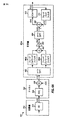
図5は判定帰還形等化を実行するプロセス500の実施形態を示している。チャネル推定値は通信チャネルに関して取得される(ブロック512)。チャネル推定値は、チャネルインパルス応答推定値、チャネル周波数応答推定値などである。等化のため使用されるフィードバックの信頼性を表す信頼性パラメータが初期化される(ブロック514)。信頼性パラメータは、フィードバック相関行列Rでもよく、信頼性係数ρでもよく、及び/又は、その他の量でもよい。信頼性パラメータは周波数に依存してもよく、又は、周波数不変性でもよい。
FIG. 5 shows an embodiment of a
フィードフォワードフィルタ応答は、チャネル推定値及び信頼性パラメータに基づいて導出される(ブロック522)。フィードバックフィルタ応答は、チャネル推定値及び信頼性パラメータに基づいて導出される(ブロック524)。フィードフォワードフィルタ応答及びフィードバックフィルタ応答は、(1)フィードバックフィルタに何ら制約を課すことなく導出され、(2)定時サンプルに対するフィードバックがないという制約を課して導出され、又は、(3)その他の制約若しくは条件に基づいて導出される。フィードフォワードフィルタ応答及びフィードバックフィルタ応答は、MMSE又はその他の規準に基づいて導出されることがある。フィードフォワードフィルタ応答とフィードバックフィルタ応答は互いに独立に導出されてもよく、フィードバックフィルタ応答がフィードフォワードフィルタ応答に基づいて導出されてもよく、又は、フィードフォワードフィルタ応答がフィードバックフィルタ応答に基づいて導出されてもよい。フィードフォワードフィルタ応答は周波数ドメイン内にあり、周波数ドメイン係数を備えている。フィードバックフィルタ応答は、(1)周波数ドメイン内にあり、周波数ドメイン係数を備えていてもよく、又は、(2)時間ドメイン内にあり、時間ドメインタップを備えていてもよい。一般に、様々なフィードフォワードフィルタ応答及びフィードバックフィルタ応答が、種々のフィルタ制約、フィードバック信頼性に関する仮定、設計規準などのため導出される。 A feedforward filter response is derived based on the channel estimate and the reliability parameter (block 522). A feedback filter response is derived based on the channel estimate and the reliability parameter (block 524). The feedforward filter response and the feedback filter response can be derived (1) without any constraints on the feedback filter, (2) with the constraint that there is no feedback on the scheduled sample, or (3) other Derived based on constraints or conditions. The feedforward filter response and the feedback filter response may be derived based on MMSE or other criteria. The feedforward filter response and the feedback filter response may be derived independently of each other, the feedback filter response may be derived based on the feedforward filter response, or the feedforward filter response may be derived based on the feedback filter response. May be. The feedforward filter response is in the frequency domain and has frequency domain coefficients. The feedback filter response may be (1) in the frequency domain and provided with frequency domain coefficients, or (2) in the time domain and provided with time domain taps. In general, various feedforward and feedback filter responses are derived due to various filter constraints, feedback reliability assumptions, design criteria, and the like.
等化はフィードフォワードフィルタ応答及びフィードバックフィルタ応答を用いて実行される(ブロック526)。等化は受信データブロック毎にブロック単位で実行されることがある。等化は複数回の反復のため実行されることもある。ブロック530において判定されるように、別の反復が実行されるべきであるならば、信頼性パラメータが更新され、次の反復のためのフィードフォワードフィルタ応答及びフィードバックフィルタ応答がチャネル推定値及び更新された信頼性パラメータに基づいて導出される。
Equalization is performed using the feedforward filter response and the feedback filter response (block 526). Equalization may be performed on a block-by-block basis for each received data block. Equalization may be performed for multiple iterations. As determined at
2.分数間隔DFE
図6Aは、受信機650aで2倍(2×)のオーバーサンプリングが行われる時間ドメインモデル600を示している。送信機610は、トラヒックデータを処理し、チップレートで送信チップs(n’)を生成し、ここで、n’はチップ期間のインデックスである。実際のシステムでは、送信機610は、通信チャネル620を介して送信チップを受信機650aへ送信する。モデル600の場合、アップサンプラー612は、各送信チップの後に零を挿入し、サンプルレートで出力サンプルs(n)を供給する。チャネル620は、ブロック624におけるチャネルインパルス応答h(n)と、加算器626を経由する加法性雑音n(n)とを用いてモデル化される。
2. Fractional interval DFE
FIG. 6A shows a
図6Aは時間ドメインフィードバックフィルタ付きの分数間隔DFEをさらに示している。用語「分数間隔」は、チップレートより高いレートでのサンプリングを表し、通常は、ナイキストのサンプリング定理によって要求されるレートより高い。受信機650aは、チップレートの2倍で受信信号をデジタル化し、チップレートの2倍であるサンプルレートで入力サンプルr(n)を取得する。ユニット652は、2K点FFT/DFTを用いて入力サンプルを周波数ドメインへ変換し、k=1,...,2Kに対して入力シンボルR(k)を供給する。受信信号の2倍のオーバーサンプリングは、利用可能な信号スペクトルの2個のコピーを生じる。2個の冗長な信号コピーは、下方コピー(L)及び上方コピー(U)のように呼ばれる。k=1,...,Kなるkに対する前半のK個の入力シンボルR(k)は、下方コピーのためのものであり、k=1,...,Kなるkに対してRL(k)のように表され、フィードフォワードフィルタ660aへ供給される。k=K+1,...,2Kなるkに対する後半のK個の入力シンボルR(k)は、上方コピーのためのものであり、k=1,...,Kなるkに対してRU(k)のように表され、フィードフォワードフィルタ660bへ供給される。
FIG. 6A further illustrates a fractionally spaced DFE with a time domain feedback filter. The term “fractional interval” refers to sampling at a rate higher than the chip rate, and is usually higher than required by the Nyquist sampling theorem.
フィードフォワードフィルタ660aは入力シンボルRL(k)をフィルタ処理し、下方コピーのためフィルタ処理されたXL(k)を供給する。フィードフォワードフィルタ660bは入力シンボルRU(k)をフィルタ処理し、上方コピーのためフィルタ処理されたXU(k)を供給する。加算器662は、ビン単位でフィルタ処理されたシンボルXL(k)及びXU(k)を加算する。ゲイン素子663は、1/2という利得を用いて加算器662の出力をスケール倍し、k=1,...,Kなるkに対してフィルタ処理されたシンボルX(k)を供給する。ユニット664は、フィルタ処理されたシンボルに関してK点IFFT/IDFTを実行し、フィルタ処理されたサンプルx(n)をチップレートで供給する。加算器662によるXL(k)とXU(k)の加算、ユニット663を用いる1/2倍のスケーリング、及び、ユニット664によるK点IFFT/IDFTは、チップレートでフィルタ処理されたサンプルx(n)を取得するために、XL(k)及びXU(k)に関して2K点IFFT/IDFTを実行し、その後に、2という倍率でデシメーションを行うことと等価である。加算器666は、フィルタ処理されたサンプルx(n)からフィードバックサンプルy(n)を減算し、等化されたサンプルz(n)を供給する。スライサ670は、等化されたサンプルz(n)をスライス化し、チップ推定値s^(n)を供給する。フィードバックフィルタ672はチップ推定値をフィルタ処理し、フィードバックサンプルy(n)を供給する。
Feed-
図6Bは、周波数ドメインフィードバックフィルタを有する分数間隔DFE付きのモデル602のブロック図を示している。送信機610及びチャネル620は図6Aのため上述された通りである。受信機650bはサンプルレートで入力サンプルr(n)を取得する。受信機650b内で、FFT/DFTユニット652と、フィードフォワードフィルタ660a及び660bと、加算器662と、ゲイン素子663が図6Aのため上述された通りに入力サンプルを操作し、フィルタ処理されたシンボルX(k)を供給する。加算器666はフィルタ処理されたシンボルX(k)からフィードバックシンボルY(k)を減算し、等化されたシンボルZ(k)を供給する。IFFT/IDFTユニット668は、等化されたシンボルを時間ドメインへ変換し、等化されたサンプルz(n)を供給する。スライサ670は等化されたサンプルz(n)をスライス化し、チップ推定値s^(n)を供給する。FFT/DFTユニット674はチップ推定値を周波数ドメインへ変換し、シンボル推定値S^(k)を供給する。フィードバックフィルタ680はシンボル推定値をフィルタ処理し、フィードバックシンボルY(k)を供給する。
FIG. 6B shows a block diagram of a model 602 with a fractionally spaced DFE with a frequency domain feedback filter.
図7は分数間隔DFE付きの周波数ドメインモデル700を示している。モデル700は図6Aのモデル600及び図6Bのモデル602と等価である。送信機710はチップレートで時間ドメイン送信チップs(n’)を生成し、時間ドメイン送信チップは通信チャネル730を介して送信される。チャネル730の場合、時間ドメイン送信チップは、k=1,...,Kなるkに対して周波数ドメイン送信シンボルS(k)を取得するために、ユニット732によってK点FFT/DFTを用いて周波数ドメインへ変換される。下方信号コピーのためのチャネルは、ブロック734aにおけるHL(k)という周波数応答、及び、加算器736aを経由するNL(k)という加法性雑音によってモデル化されている。上方信号コピーのためのチャネルは、ブロック734bにおけるHU(k)という周波数応答、及び、加算器736bを経由するNU(k)という加法性雑音によってモデル化されている。ユニット738は時間ドメイン雑音n(n)を変換し、下方コピー及び上方コピーのそれぞれのための周波数ドメイン雑音NL(k)及びNU(k)を供給する。
FIG. 7 shows a
受信機750は、下方コピー及び上方コピーのそれぞれのための入力シンボルRL(k)及びRU(k)を取得する。フィードフォワードフィルタ760a及び760bは入力シンボルRL(k)及びRU(k)をフィルタ処理し、フィルタ処理されたシンボルXL(k)及びXU(k)をそれぞれ供給する。フィルタ処理されたシンボルXL(k)及びXU(k)は、フィルタ処理されたシンボルX(k)を取得するために、加算器762によって加算され、ゲイン素子763によって1/2という利得でスケール倍される。加算器766は、フィルタ処理されたシンボルX(k)からフィードバックシンボルY(k)を減算し、等化されたサンプルZ(k)を供給する。等化されたシンボルZ(k)は、チップ推定値s^(n)を取得するために、IFFT/IDFTユニット768によって時間ドメインへ変換され、スライサ770によってスライス化される。チップ推定値は、フィードバックシンボルを取得するために、FFT/DFTユニット774によって周波数ドメインへ変換され、フィードバックフィルタ780によってフィルタ処理される。
入力シンボルは、以下の通り、1個のデータブロックについて行列形式で表現される。
ここで、HLは、下方コピーのためのK×K対角チャネル応答行列であり、
HU は、上方コピーのためのK×K対角チャネル応答行列であり、
rLは、下方コピーのための受信シンボルのK×1ベクトルであり、
rUは、上方コピーのための受信シンボルのK×1ベクトルであり、
nL、nUはそれぞれ、下方コピー、上方コピーのためのK×1雑音ベクトルである。
Where H L is the K × K diagonal channel response matrix for the downward copy,
H U is the K × K diagonal channel response matrix for the upper copy,
r L is the K × 1 vector of received symbols for the lower copy,
r U is the K × 1 vector of received symbols for the upper copy,
n L and n U are K × 1 noise vectors for the lower copy and the upper copy, respectively.
フィードフォワードフィルタ760a及び760bからのフィルタ処理されたシンボルは、
で表現され、ここで、FL、FU はそれぞれ、下方コピー、上方コピーのフィードフォワードフィルタ応答のためのK×K対角行列であり、
xL、xU はそれぞれ、下方コピー、上方コピーのためのK×1フィルタ処理シンボルベクトルである。
Where F L and F U are K × K diagonal matrices for the lower copy and upper copy feedforward filter responses, respectively,
x L and x U are K × 1 filtered symbol vectors for the lower copy and the upper copy, respectively.
フィードバックフィルタ780からのフィードバックシンボルyは
で表現される。 It is expressed by
スライサ770へ供給された等化されたサンプルzは、
で表現され、ここで、W2kは、2K×2Kフーリエ行列であり、n2kは、2K×1雑音ベクトルである。式(31)中の全ての他の行列はK×K行列であり、全ての他のベクトルはK×1ベクトルである。 Where W 2k is a 2K × 2K Fourier matrix and n 2k is a 2K × 1 noise vector. All other matrices in equation (31) are K × K matrices, and all other vectors are K × 1 vectors.
フィードフォワードフィルタ周波数応答FL、FU及びフィードバックフィルタ周波数応答Bは、式(13)及び’(14)に示されている仮定を用いて式(12)に示されているMSEを最小化するMMSE規準に基づいて導出されることもある。式(12)は、展開され、式(13)、(14)及び(31)と組み合わされることがある。MSEは、以下のように表現される。
ここで、FL(k)、FU(k)、HL(k)、HU(k)は、それぞれ、K×K行列F L、F U、H L、H Uのk番目の対角要素である。 Here, F L (k), F U (k), H L (k), and H U (k) are the k-th pairs of K × K matrices F L , F U , H L , and H U , respectively. It is a corner element.
一実施形態では、フィードフォワードフィルタ応答及びフィードバックフィルタ応答は、フィードバックフィルタに制約を課すことなく導出される。この実施形態の場合、フィードバックフィルタインパルス応答は、L×1ベクトル
によって与えられる。 Given by.
式(32)から、フィードフォワードフィルタ応答は、
で与えられ、ここで、c=L,Uのとき、Hc(k)はコピーcにおける周波数ビンkのチャネル利得であり、c=L,Cのとき、Fc(k)はコピーcにおけるビンkのフィードフォワードフィルタ係数である。 Where H c (k) is the channel gain of frequency bin k at copy c when c = L, U, and F c (k) is at copy c when c = L, C. This is the feed forward filter coefficient of bin k.
フィードバックフィルタ応答は、
で与えられる。 Given in.
別の実施形態では、フィードフォワードフィルタ応答及びフィードバックフィルタ応答は、フィードバックフィルタに対するb0=0という制約を用いて導出される。この実施形態の場合、フィードバックフィルタインパルス応答は、L×1ベクトル
によって与えられる。計算を減らすために、Lは、Kより遙かに小さいが、重要なISIコンポーネントをカバーするために十分に大きくなるように選択されることがある。 Given by. To reduce computation, L may be chosen to be much smaller than K but large enough to cover important ISI components.
フィードバックフィルタ応答は、式(18)及び(19)に示されているように与えられることがあり、この場合、行列Q要素は、m,l=1,...,(L−1)のとき、
で与えられる。 Given in.
ベクトルpの要素は、m=1,...,(L−1)のとき、
で与えられる。 Given in.
式(32)から、b0=0という制約を用いて、フィードフォワードフィルタ応答は、
で与えられる。 Given in.
さらに別の実施形態では、フィードフォワードフィルタ応答及びフィードバックフィルタ応答は、フィードバックフィルタのb0=0という制約と、R(k,k)=ρかつL=Kとを用いて導出される。この実施形態の場合、フィードフォワードフィルタ応答は、以下の式で与えられる。
フィードバックフィルタ応答は、以下の式で与えられる。
さらに別の実施形態では、フィードフォワードフィルタ応答及びフィードバックフィルタ応答は、フィードバックフィルタのb0=0という制約と、フィードバックエラーが存在しない、かつR(k,k)=1であるという仮定とを用いて導出され、s^(n)=s(n)かつR(k、k)=1である。この実施形態の場合、フィードバックフィルタ応答は、式(18)及び(19)に示されているように与えられ、ここで、
である。 It is.
フィードフォワードフィルタ応答は、
で与えられる。 Given in.
図8は、分数間隔フィードフォワードフィルタ応答及びフィードバックフィルタ応答を導出し、入力シンボルを等化するプロセス800の実施形態を示している。最初に、下方信号コピー及び上方信号コピーのそれぞれのためのチャネル周波数応答HL(k)及びHU(k)を取得するために、チャネルインパルス応答h(n)が推定され、FFT/DFTを用いて変換される(ブロック812)。フィードバック相関行列R又は信頼性係数ρは、1回目の反復のため、たとえば、零に初期化される(ブロック814)。
FIG. 8 shows an embodiment of a
下方コピー及び上方コピーのためのフィードフォワードフィルタ応答FL(k)及びFU(k)は、たとえば、式(33)、(37)、(38)又は(42)に示されているように、チャネル周波数応答HL(k)及びHU(k)と、フィードバック相関R(k,k)又は信頼性係数ρとに基づいて導出される(ブロック822)。フィードバックフィルタ応答B(k)は同様に、式(34)、(35)及び(36)、(39)又は(40)及び(41)に示されているように、チャネル周波数応答HL(k)及びHU(k)と、フィードバック相関R(k,k)又は信頼性係数ρとに基づいて導出される(ブロック824)。等化は、たとえば、式(29)乃至(31)に示されているように、フィードフォワードフィルタ応答及びフィードバックフィルタ応答に基づいて下方コピー及び上方コピーのための入力シンボルRL(k)及びRU(k)に実行される(ブロック826)。等化されたシンボルは、チップ推定値s^(n)を取得するために変換されスライス化される(ブロック828)。 The feedforward filter responses F L (k) and F U (k) for the lower and upper copies are, for example, as shown in equations (33), (37), (38) or (42) , Based on the channel frequency response H L (k) and H U (k) and the feedback correlation R (k, k) or the reliability factor ρ (block 822). The feedback filter response B (k) is likewise the channel frequency response H L (k, as shown in equations (34), (35) and (36), (39) or (40) and (41). ) And H U (k) and a feedback correlation R (k, k) or a reliability factor ρ (block 824). The equalization is performed, for example, as shown in equations (29)-(31), based on the feedforward filter response and the feedback filter response, input symbols R L (k) and R for the lower copy and the upper copy. U (k) is executed (block 826). The equalized symbols are transformed and sliced to obtain chip estimates s ^ (n) (block 828).
等化は1回又は複数回の反復のため実行される。別の反復を実行するかどうかについての判定が行われる(ブロック830)。応答が「はい」であるならば、フィードバック相関行列R又は信頼性係数ρが更新される(ブロック832)。プロセスは、その後、ブロック822へ戻り、フィードフォワードフィルタ応答及びフィードバックフィルタ応答を更新し、更新されたフィルタ応答を用いて等化を実行する。そうでなければ、全ての反復が完了し、ブロック830の応答が「いいえ」であるならば、プロセスは終了する。
Equalization is performed for one or more iterations. A determination is made as to whether to perform another iteration (block 830). If the response is “yes”, the feedback correlation matrix R or the reliability factor ρ is updated (block 832). The process then returns to block 822 to update the feedforward filter response and the feedback filter response and perform equalization using the updated filter response. Otherwise, if all iterations are complete and the response of
明確にするために、分数間隔DFEは、受信機における2倍のオーバーサンプリング、すなわち、Cがオーバーサンプリング比である場合に、C=2に関して説明されている。一般に、分数間隔DFEはいかなるオーバーサンプリング量と共に使用してもよい。上記の式では、項
は
で置き換えてもよく、添字cは1からCまで変化し、2という倍率は必要に応じてCで置き換えられる。 The subscript c changes from 1 to C, and the magnification of 2 is replaced by C as necessary.
明確にするために、チップ間隔DFE及び分数間隔DFEは受信機に単一の受信アンテナがある場合について説明されている。本明細書に記載されているDFEは、受信ダイバーシティ又はマルチ入力マルチ出力(MIMO)伝送のため利用される複数(R)本のアンテナをもつ受信機のためにも使用される。受信ダイバーシティを伴うチップレートサンプリングの場合、受信機は、R本の受信アンテナのためのR個の信号コピー及びR個のチャネル周波数応答を取得する。受信機は、たとえ、信号スペクトルの異なる部分ではなく、異なる受信アンテナからの信号コピーであるとしても、たとえば、分数間隔DFEに関して上述された内容に基づいて、R個の信号コピーのためのR個のフィードフォワードフィルタ応答を導出する。受信ダイバーシティを用いるオーバーサンプリングの場合、受信機は、R本の受信アンテナ及びC倍のオーバーサンプリングに対して、R−C個の信号コピー及びR−C個のチャネル周波数応答を取得する。受信機は、たとえ、異なる受信アンテナであると同時に、信号スペクトルの異なる部分からの信号コピーであるとしても、たとえば、分数間隔DFEに関して上述された内容に基づいて、R−C個の信号コピーのためのR−C個のフィードフォワードフィルタ応答を導出する。 For clarity, the chip spacing DFE and fractional spacing DFE are described for the case where the receiver has a single receive antenna. The DFE described herein is also used for receivers with multiple (R) antennas utilized for receive diversity or multi-input multi-output (MIMO) transmission. For chip rate sampling with receive diversity, the receiver obtains R signal copies and R channel frequency responses for the R receive antennas. The receiver may be R copies for R signal copies, for example, based on what has been described above for fractionally spaced DFE, even if the signal copies are from different receive antennas rather than different portions of the signal spectrum. The feedforward filter response of is derived. For oversampling using receive diversity, the receiver obtains RC signal copies and RC channel frequency responses for R receive antennas and C times oversampling. Even though the receiver is a different receive antenna and at the same time a signal copy from a different part of the signal spectrum, for example, based on what has been described above for the fractionally spaced DFE, Deriving RC feedforward filter responses for
図9は、複数本の受信アンテナ及び/又はオーバーサンプリングを用いて取得される複数個の信号コピーのための判定帰還形等化を実行するプロセス900の実施形態を示している。チャネル推定値は複数の信号コピーのため取得される(ブロック912)。チャネル推定値は、チャネルインパルス応答推定値、チャネル周波数応答推定値などでもよい。フィードバック相関行列R、信頼性係数ρ、及び/又は、その他の量でもよい信頼性パラメータが初期化される(ブロック914)。
FIG. 9 shows an embodiment of a
複数の信号コピーのためのフィードフォワードフィルタ応答は、チャネル推定値及び信頼性パラメータに基づいて導出される(ブロック922)。フィードバックフィルタ応答は、チャネル推定値及び信頼性パラメータに基づいて導出される(ブロック924)。フィードフォワードフィルタ応答及びフィードバックフィルタ応答は、(1)フィードバックフィルタに全く制約を課すことなく導出され、(2)定時サンプルに対するフィードバックがないという制約を課して導出され、又は、(3)その他の制約又は条件に基づいて導出される。フィードフォワードフィルタ応答及びフィードバックフィルタ応答は、MMSE又はその他の規準に基づいて導出されてもよい。フィードフォワードフィルタ応答とフィードバックフィルタ応答は独立に導出されてもよく、フィードバックフィルタ応答はフィードフォワードフィルタ応答に基づいて導出されてもよく、又は、フィードフォワードフィルタ応答はフィードバックフィルタ応答に基づいて導出されてもよい。一般に、様々なフィードフォワードフィルタ応答及びフィードバックフィルタ応答が種々のフィルタ制約、フィードバック信頼性に関する仮定、設計規準などのため導出される。 A feedforward filter response for multiple signal copies is derived based on the channel estimate and the reliability parameter (block 922). A feedback filter response is derived based on the channel estimate and the reliability parameter (block 924). The feedforward filter response and the feedback filter response can be derived (1) without any constraints on the feedback filter, (2) with the constraint that there is no feedback on the timed samples, or (3) other Derived based on constraints or conditions. The feedforward filter response and the feedback filter response may be derived based on MMSE or other criteria. The feedforward filter response and the feedback filter response may be derived independently, the feedback filter response may be derived based on the feedforward filter response, or the feedforward filter response may be derived based on the feedback filter response. Also good. In general, various feedforward and feedback filter responses are derived for various filter constraints, feedback reliability assumptions, design criteria, and the like.
等化は、フィードフォワードフィルタ応答及びフィードバックフィルタ応答を用いて実行される(ブロック926)。等化は、受信データブロック毎にブロック単位で実行されることがある。等化は複数回の反復のため実行されてもよい。ブロック930において判定されるように、別の反復が実行されるべきであるならば、信頼性パラメータがブロック932において更新され、次の反復のためのフィードフォワードフィルタ応答及びフィードバックフィルタ応答がチャネル推定値及び更新された信頼性パラメータに基づいて導出される。
Equalization is performed using the feedforward filter response and the feedback filter response (block 926). Equalization may be performed on a block-by-block basis for each received data block. Equalization may be performed for multiple iterations. If another iteration is to be performed, as determined at
3.判定帰還信頼性
フィードフォワードフィルタ応答及びフィードバックフィルタ応答は、チップ推定値s^(n)の信頼性に関連したR(k,k)又はρに基づいて導出される。チップ推定値は等化のためフィードバックされる一時的な判定である。フィードバックの量は、チップ推定値が統計的にどの程度信頼できるかに関連している。フィードバックの量は、チップ推定値が非常に信頼できるならば大きく、チップ推定値があまり信頼できないならば小さい。極端なケースでは、チップ推定値が全く信頼できないならば、フィードバックはない。
3. Decision Feedback Reliability The feedforward filter response and the feedback filter response are derived based on R (k, k) or ρ related to the reliability of the chip estimate s ^ (n). The chip estimate is a temporary decision that is fed back for equalization. The amount of feedback is related to how reliable the chip estimate is statistically. The amount of feedback is large if the chip estimate is very reliable and small if the chip estimate is not very reliable. In extreme cases, if the chip estimate is totally unreliable, there is no feedback.
チップ推定値の信頼性は様々な方式で推定される。一実施形態では、信頼性は正しく復号化されたブロックに基づいて推定される。巡回冗長検査(CRC)符号のような誤り検出符号は、所与のブロックが正しく復号化されているかどうかを判定するため使用される。送信機は、データブロックのためのCRCを生成し、データブロックの一部としてCRCを添付する。受信機は、添付されたCRCを誤り検出のため使用する。ブロックを復号化した後、受信機は、復号化されたブロックに基づいてCRCを生成し、生成されたCRCを添付されたCRCと比較する。2つのCRCが一致するならば、ブロックは正しく復号化されているとみなされ、そのブロック内の全てのチップが受信機に分かるようになる。 The reliability of the chip estimated value is estimated by various methods. In one embodiment, the reliability is estimated based on correctly decoded blocks. An error detection code, such as a cyclic redundancy check (CRC) code, is used to determine whether a given block has been decoded correctly. The transmitter generates a CRC for the data block and attaches the CRC as part of the data block. The receiver uses the attached CRC for error detection. After decoding the block, the receiver generates a CRC based on the decoded block and compares the generated CRC with the attached CRC. If the two CRCs match, the block is considered correctly decoded and all the chips in the block are known to the receiver.
受信機は、等化の様々なステージ又は反復でチップ推定値の信頼性を計算するため、正しく復号化されたブロックを使用する。受信機は、送信機によって実行された方式と同じ方式で復号化されたブロックを処理し、このデータブロックのため送信機によって送信された送信チップs(n)を再生成する。一実施形態では、受信機は、送信チップs(n)を、所与のステージのためのチップ推定値s^i(n)と相関させ、このステージiのための信頼性係数ρiを次の通り取得する。
別の実施形態では、受信機は、ステージiに対するフィードバック相関行列Riを、以下のように導出する。
ここで、s^iは、ステージiのシンボル推定値のK×1ベクトルである。 Here, s i is a K × 1 vector of symbol estimates of stage i.
種々のチップ推定値が取得され、異なるステージにおける等化のためフィードバックされる。したがって、受信機は、様々なステージのチップ推定値に基づいてこれらのステージのためのフィードバック信頼性を推定する。 Various chip estimates are obtained and fed back for equalization at different stages. Thus, the receiver estimates the feedback reliability for these stages based on the chip estimates for the various stages.
判定帰還の信頼性は、変動を低減するために、複数の正しく復号化されたブロックに亘ってフィルタ処理される。フィルタリングは、有限インパルス応答(FIR)フィルタ、無限インパルス応答(IIR)フィルタ、又は、その他のタイプのフィルタに基づいて実行される。フィルタの時定数又は帯域幅は、チャネル条件の期待される変化率に基づいて選択される。大きい時定数又は小さい帯域幅が緩やかに変化するチャネルのため使用される。逆に、小さい時定数又は大きい帯域幅が速く変化するチャネルのため使用される。フィルタの時定数は受信機のドップラーに基づいて適応的であってもよい。 The reliability of decision feedback is filtered across multiple correctly decoded blocks to reduce variation. Filtering is performed based on a finite impulse response (FIR) filter, an infinite impulse response (IIR) filter, or other types of filters. The time constant or bandwidth of the filter is selected based on the expected rate of change of channel conditions. Large time constants or small bandwidths are used for slowly changing channels. Conversely, small time constants or large bandwidths are used for fast changing channels. The filter time constant may be adaptive based on the receiver Doppler.
隣接したデータブロックは、等化の同じステージのための近似的に類似した判定帰還信頼性を有すると仮定される。この場合、正しく復号化されたブロックに基づいて様々なステージに対して推定された信頼性は将来のブロックの判定帰還形等化のため使用される。 Adjacent data blocks are assumed to have approximately similar decision feedback reliability for the same stage of equalization. In this case, the reliability estimated for the various stages based on correctly decoded blocks is used for decision feedback equalization of future blocks.
判定帰還の信頼性は送信機によって使用される変調スキームに依存する。一実施形態では、フィードバック信頼性は様々な変調スキームに対して推定され維持される。この実施形態では、所与の変調スキームを用いて送信され、正しく復号化されたブロックのため推定された信頼性は、同じ変調スキームを用いて送信された将来のブロックの等化のため使用される。別の実施形態では、フィードバック信頼性は、正しく復号化されたブロックのため使用された様々な変調スキームを考慮した方式で推定される。 The reliability of decision feedback depends on the modulation scheme used by the transmitter. In one embodiment, feedback reliability is estimated and maintained for various modulation schemes. In this embodiment, the reliability estimated for a correctly decoded block transmitted using a given modulation scheme is used for equalization of future blocks transmitted using the same modulation scheme. The In another embodiment, the feedback reliability is estimated in a manner that considers the various modulation schemes used for the correctly decoded block.
判定帰還の信頼性は、先験的に知られているか、又は、受信機によって確認されているその他の伝送内容に基づいて推定されることがある。たとえば、データブロックが既知部分(たとえば、固有語、プレアンブル、及び/又は、その他の既知情報)を含むならば、フィードバック信頼性はこの既知部分に基づいて推定される。 The reliability of decision feedback may be known based on a priori or may be estimated based on other transmission content ascertained by the receiver. For example, if the data block includes a known portion (eg, proper words, preambles, and / or other known information), feedback reliability is estimated based on the known portion.
受信機は、フィードフォワードフィルタ応答及びフィードバックフィルタ応答を導出するため、推定されたフィードバック信頼性を使用する。受信機はさらに、判定帰還形等化を実行するか、又は、(判定帰還なしの)線形等化を実行するかを判定するためにフィードバック信頼性を使用する。たとえば、受信機は、フィードバックがあまりにも信頼できないならば、線形等化を実行する。 The receiver uses the estimated feedback reliability to derive the feedforward filter response and the feedback filter response. The receiver further uses feedback reliability to determine whether to perform decision feedback equalization or linear equalization (without decision feedback). For example, the receiver performs linear equalization if the feedback is too unreliable.
図10は、正しく復号化されたブロックから導出された信頼性パラメータに基づいて判定帰還形等化を実行するプロセス1000の実施形態を示している。信頼性パラメータは、CRC又はその他の誤り検出符号に基づいて判定される正しく復号化された1番目のデータブロックに基づいて推定される(ブロック1012)。信頼性パラメータは、(1)たとえば、式(43)に示されているように、送信チップとチップ推定値との相関に基づいて、又は、(2)たとえば、式(44)に示されているように、送信シンボルとシンボル推定値との外積に基づいて推定される。信頼性パラメータは複数の正しく復号化されたブロックの全体を通じてフィルタ処理されることがある。フィルタリングの時定数は、チャネル条件及び/又はその他の要因に基づいて選択される。
FIG. 10 shows an embodiment of a
フィードフォワードフィルタ応答及びフィードバックフィルタ応答は、チャネル推定値及び信頼性パラメータに基づいて導出される(ブロック1014)。等化は、フィードフォワードフィルタ応答及びフィードバックフィルタ応答を用いて2番目のデータブロックに対し実行される(ブロック1016)。等化が複数の反復又はステージにおいて実行されるならば、信頼性パラメータは、ステージ毎に、このステージの1番目のデータブロックとチップ又はシンボル推定値とに基づいて推定される。反復毎のフィードフォワードフィルタ応答及びフィードバックフィルタ応答は、その反復のための信頼性パラメータに基づいて導出される。 A feedforward filter response and a feedback filter response are derived based on the channel estimate and the reliability parameter (block 1014). Equalization is performed on the second data block using the feedforward filter response and the feedback filter response (block 1016). If equalization is performed in multiple iterations or stages, the reliability parameter is estimated for each stage based on the first data block of this stage and the chip or symbol estimates. The feed forward filter response and feedback filter response for each iteration are derived based on the reliability parameter for that iteration.
図11は、通信システム1100における送信機1110及び受信機1150の実施形態のブロック図を示している。ダウンリンク/順方向リンク伝送の場合、送信機1110は基地局の一部であり、受信機1150は無線機器の一部である。アップリンク/逆方向リンク伝送の場合、送信機1110は無線機器の一部であり、受信機1150は基地局の一部である。基地局は、典型的に、無線機器と通信し、ノードB、アクセスポイントなどのように呼ばれる固定局である。無線機器は、固定式又は移動式であり、ユーザ機器(UE)、移動局、ユーザ端末、加入者ユニットなどのように呼ばれることもある。無線機器は、携帯電話機、個人情報端末(PDA)、無線モデムカード、又は、その他の機器又は装置でもよい。
FIG. 11 shows a block diagram of an embodiment of a
送信機1110では、送信(TX)データプロセッサ1120がトラヒックデータを処理(たとえば、符号化、インターリーブ化、及び、シンボルマップ化)し、データシンボルを生成する。本明細書中で使用されているように、データシンボルはデータの変調シンボルであり、パイロットシンボルはパイロットの変調シンボルであり、変調シンボルは(たとえば、M−PSK又はM−QAMのための)信号コンスタレーション内の点の複素値であり、パイロットは、送信機と受信機の双方によって先験的に知られているデータである。変調器1130は、システムによって指定された方式でデータシンボル及びパイロットシンボルを処理し、送信チップs(n)を送信機ユニット(TMTR)1132へ供給する。送信機ユニット1132は、送信チップを処理(たとえば、アナログに変換、増幅、フィルタ処理、及び、周波数アップコンバート)し、アンテナ1134から伝送されるRF信号を生成する。
At
受信機1150では、アンテナ1152が種々の信号路を経由して伝送されたRF信号を受信し、受信信号を受信機ユニット(RCVR)1154へ供給する。受信機ユニット1154は、受信信号を条件付け(たとえば、フィルタ処理、増幅、及び、周波数ダウンコンバート)し、条件付けられた信号をチップレート以上であるサンプルレートでデジタル化し、時間ドメイン入力サンプルを供給する。FFT/DFTユニット1156は入力サンプルを周波数ドメインへ変換し、周波数ドメイン入力シンボルを供給する。
In the
チャネル及び雑音推定器1158は、周波数ドメイン入力シンボル及び/又は時間ドメイン入力サンプルに基づいてチャネル応答及び雑音を推定する。判定帰還形等化器(DFE)1160は、チャネル及び雑音推定値と信頼性パラメータとに基づいて(複数の)フィードフォワードフィルタ応答及びフィードバックフィルタ応答を導出する。信頼性パラメータは、正しく復号化されたブロック及び/又はその他の既知の伝送内容に基づいて、DFE1160、コントローラ1190、又は、その他のユニットによって推定され更新される。
Channel and
DFE1160は、フィードフォワードフィルタ応答及びフィードバックフィルタ応答に基づいて入力シンボルをフィルタ処理し、チップ推定値を復調器(Demod)1170へ供給する。DFE1160は、上述されたDFE設計の何れを実施してもよい。復調器1170は、変調器1130による処理と相補的な方式でチップ推定値を処理し、データシンボル推定値を供給する。受信(RX)データプロセッサ1180は、データシンボル推定値を処理(たとえば、シンボルデマップ化、デインターリーブ化、及び、復号化)し、復号化されたデータを供給する。RXデータプロセッサ1180はCRCに基づいて各データブロックを検査することもある。一般に、復調器1170及びRXデータプロセッサ1180による処理は、送信機1110における変調器1130及びTXデータプロセッサ1120のそれぞれによる処理と相補的である。
The DFE 1160 filters the input symbols based on the feedforward filter response and the feedback filter response and provides the chip estimate to a demodulator (Demod) 1170. The DFE 1160 may implement any of the DFE designs described above.
コントローラ/プロセッサ1140及び1190は、送信機1110及び受信機1150のそれぞれにおける種々の処理ユニットの動作を命令する。メモリ1142及び1192は、送信機1110及び受信機1150のそれぞれのためのデータ及びプログラムコードを記憶する。
Controllers /
本明細書に記載されている等化技術は、符号分割多元接続(CDMA)システム、時分割多元接続(TDMA)システム、周波数分割多元接続(FDMA)システム、直交FDMA(OFDMA)システム、シングルキャリアFDMA(SC−FDMA)などのような様々な通信システムのため使用される。CDMAシステムは、広帯域CDMA(W−CDMA)、cdma2000などのような1つ以上の無線技術を実施する。cdma2000は、IS−2000標準規格、IS−856標準規格、及び、IS−95標準規格を対象とする。TDMAシステムは、グローバル移動体通信システム(GSM)のような無線技術を実施する。これらの様々な無線技術及び標準規格は技術的に知られている。OFDMAシステムは、直交周波数分割多重(OFDM)を使用して直交サブキャリア上の周波数ドメイン内で変調シンボルを伝送する。SC−FDMAシステムは、直交サブキャリア上の時間ドメイン内で変調シンボルを伝送する。 The equalization techniques described herein include code division multiple access (CDMA) systems, time division multiple access (TDMA) systems, frequency division multiple access (FDMA) systems, orthogonal FDMA (OFDMA) systems, single carrier FDMA. Used for various communication systems such as (SC-FDMA). A CDMA system implements one or more radio technologies such as Wideband CDMA (W-CDMA), cdma2000, and so on. cdma2000 covers the IS-2000 standard, the IS-856 standard, and the IS-95 standard. A TDMA system implements a radio technology such as Global System for Mobile Communications (GSM). These various radio technologies and standards are known in the art. An OFDMA system transmits modulation symbols in the frequency domain on orthogonal subcarriers using orthogonal frequency division multiplexing (OFDM). SC-FDMA systems transmit modulation symbols in the time domain on orthogonal subcarriers.
送信機1110における変調器1130及び受信機1150における復調器1170はシステムによって指定されるような処理を実行する。たとえば、変調器1130は、CDMA、OFDM、SC−FDMAなど、又は、これらの組み合わせのための処理を実行する。
当業者は、情報及び信号が多種多様なテクノロジー及び技術のうちのどれを使用して表現されても構わないことを理解するであろう。たとえば、上記の説明を通じて参照されているデータ、命令、コマンド、情報、信号、ビット、シンボル及びチップは、電圧、電流、電磁波、磁場若しくは磁性粒子、光場若しくは光粒子、又は、これらの任意の組み合わせによって表現される。 Those skilled in the art will appreciate that information and signals may be represented using any of a wide variety of technologies and techniques. For example, data, commands, commands, information, signals, bits, symbols and chips referenced throughout the above description may be voltage, current, electromagnetic wave, magnetic field or magnetic particle, light field or light particle, or any of these Expressed by a combination.
当業者は、本明細書中に開示されている実施形態と関連して記載された種々の実例のための論理ブロック、モジュール、回路、及び、アルゴリズムステップが、電子ハードウェア、コンピュータソフトウェア、又は、両者の組み合わせとして実施されることをさらに認めるであろう。このハードウェアとソフトウェアの互換性を明瞭に説明するために、種々の実証のためのコンポーネント、ブロック、モジュール、回路、及び、ステップは、一般にこれらの機能の点に関して上述されている。このような機能がハードウェアとソフトウェアのどちらで実施されるかは、特定のアプリケーション、及び、システム全体に課された設計制約に依存する。当業者は、記載された機能を特定の各アプリケーションのための様々な方式で実施するが、このような実施決定は本発明の範囲からの逸脱を生じさせるものとして解釈されるべきでない。 Those skilled in the art will recognize that the logic blocks, modules, circuits, and algorithm steps for the various examples described in connection with the embodiments disclosed herein are electronic hardware, computer software, or It will be further appreciated that it is implemented as a combination of both. To clearly illustrate this hardware and software compatibility, the various demonstration components, blocks, modules, circuits, and steps are generally described above in terms of their functionality. Whether such functionality is implemented in hardware or software depends on the particular application and design constraints imposed on the overall system. Those skilled in the art will implement the described functionality in various ways for each specific application, but such implementation decisions should not be construed as causing a departure from the scope of the invention.
本明細書中に開示された実施形態に関連して記載された種々の実証のための論理ブロック、モジュール、及び、回路は、本明細書中に記載されている機能を実行するため設計された汎用プロセッサ、デジタル信号プロセッサ(DSP)、特定用途向け集積回路(ASIC)、フィールド・プログラマブル・ゲート・アレイ(FPGA)若しくはその他のプログラマブルロジックデバイス、ディスクリートゲート若しくはトランジスタロジック、ディスクリートハードウェアコンポーネント、又は、これらの任意の組み合わせを用いて実施又は実行される。汎用プロセッサはマイクロプロセッサでもよいが、代案として、プロセッサは、いかなる従来型のプロセッサ、コントローラ、マイクロコントローラ、又は、状態機械でもよい。プロセッサは、計算装置の組み合わせ、たとえば、DSP及びマイクロプロセッサの組み合わせ、複数台のマイクロプロセッサ、DSPコアを伴う1台以上のマイクロプロセッサ、又は、その他の任意のこのような構成として実施されることもある。 The various demonstration logic blocks, modules, and circuits described in connection with the embodiments disclosed herein are designed to perform the functions described herein. General purpose processor, digital signal processor (DSP), application specific integrated circuit (ASIC), field programmable gate array (FPGA) or other programmable logic device, discrete gate or transistor logic, discrete hardware components, or these Implementation or execution using any combination of A general purpose processor may be a microprocessor, but in the alternative, the processor may be any conventional processor, controller, microcontroller, or state machine. The processor may also be implemented as a combination of computing devices, eg, a combination of DSP and microprocessor, multiple microprocessors, one or more microprocessors with a DSP core, or any other such configuration. is there.
本明細書中に開示された実施形態に関連して記載された方法又はアルゴリズムのステップは、直接的にハードウェアで、プロセッサによって実行されるソフトウェアモジュールで、又は、両者の組み合わせで具現化される。ソフトウェアモジュールは、RAMメモリ、フラッシュメモリ、ROMメモリ、EPROMメモリ、EEPROMメモリ、レジスタ、ハードディスク、リムーバルディスク、CD−ROM、又は、技術的に知られているその他の形式の記憶媒体に存在する。例示的な記憶媒体は、プロセッサが記憶媒体から情報を読み出し、記憶媒体に情報を書き込むことができるように、プロセッサに連結されている。代案として、記憶媒体はプロセッサと一体化されていてもよい。プロセッサ及び記憶媒体はASIC内に存在していてもよい。ASICはユーザ端末に存在することがある。代案として、プロセッサ及び記憶媒体はユーザ端末内にディスクリートコンポーネントとして存在することがある。 The method or algorithm steps described in connection with the embodiments disclosed herein may be implemented directly in hardware, in software modules executed by a processor, or in a combination of both. . A software module resides in RAM memory, flash memory, ROM memory, EPROM memory, EEPROM memory, registers, hard disk, removable disk, CD-ROM, or other type of storage medium known in the art. An exemplary storage medium is coupled to the processor such that the processor can read information from, and write information to, the storage medium. In the alternative, the storage medium may be integral to the processor. The processor and the storage medium may exist in the ASIC. The ASIC may exist in the user terminal. In the alternative, the processor and the storage medium may reside as discrete components in a user terminal.
見出しは、参考のため、かつ、ある特定の欄を見つけるために役立つように本明細書に含まれている。これらの見出しは請求の範囲に記載されている概念の範囲を制限することを目的とするのではなく、これらの概念は明細書全体を通じてその他の欄においても適用される。 Headings are included herein for reference and to help find certain columns. These headings are not intended to limit the scope of the concepts recited in the claims, but these concepts apply throughout the specification and elsewhere.
上記の開示された実施形態の説明は、当業者が本発明を構成又は使用できるようにするために記載されている。これらの実施形態に対する種々の変更は当業者に直ぐに理解され、これらの実施形態に規定されている一般的な原理は本発明の精神又は範囲から逸脱することなくその他の実施形態に適用される。したがって、本発明は、本明細書に示されている実施形態に限定されることが意図されるものではなく、本明細書中に開示された原理及び新規性のある特徴と一致する最も広い範囲が認められるべきである。 The above description of the disclosed embodiments is provided to enable any person skilled in the art to make or use the present invention. Various modifications to these embodiments will be readily apparent to those skilled in the art, and the generic principles defined in these embodiments may be applied to other embodiments without departing from the spirit or scope of the invention. Accordingly, the present invention is not intended to be limited to the embodiments shown herein but is to be accorded the widest scope consistent with the principles and novel features disclosed herein. Should be accepted.
Claims (42)
前記少なくとも1台のプロセッサに連結されているメモリと、
を備える装置。 Deriving a feedforward filter response and a feedback filter response based on the channel estimate and the reliability parameter, and without using a constraint on the feedback filter response or using a no feedback constraint on the fixed-time sample, At least one processor for performing equalization using a response and the feedback filter response;
A memory coupled to the at least one processor;
A device comprising:
前記フィードフォワードフィルタ応答及び前記フィードバックフィルタ応答を用いて等化を実行することと、
を備える方法。 Deriving a feedforward filter response and a feedback filter response based on the channel estimate and the reliability parameter, and further without a constraint on the feedback filter response or with a no feedback constraint on the timed sample;
Performing equalization using the feedforward filter response and the feedback filter response;
A method comprising:
前記フィードフォワードフィルタ応答及び前記フィードバックフィルタ応答を導出することは、
反復毎に前記信頼性パラメータを更新することと、
前記チャネル推定値及び前記反復毎の前記信頼性パラメータに基づいて、反復毎に前記フィードフォワードフィルタ応答及び前記フィードバックフィルタ応答を導出することと、
を備える、
請求項11に記載の方法。 Equalization is performed for multiple iterations,
Deriving the feedforward filter response and the feedback filter response includes
Updating the reliability parameter at each iteration;
Deriving the feedforward filter response and the feedback filter response for each iteration based on the channel estimate and the reliability parameter for each iteration;
Comprising
The method of claim 11.
前記フィードフォワードフィルタ応答及び前記フィードバックフィルタ応答を用いて等化を実行する手段と、
を備える装置。 Means for deriving a feedforward filter response and a feedback filter response based on the channel estimate and the reliability parameter, and further without a constraint on the feedback filter response or using a no feedback constraint on the timed sample;
Means for performing equalization using the feedforward filter response and the feedback filter response;
A device comprising:
前記フィードフォワードフィルタ応答及び前記フィードバックフィルタ応答を導出する手段は、
反復毎に前記信頼性パラメータを更新する手段と、
前記チャネル推定値及び前記反復毎の前記信頼性パラメータに基づいて、反復毎に前記フィードフォワードフィルタ応答及び前記フィードバックフィルタ応答を導出する手段と、
を備える、
請求項14に記載の装置。 Equalization is performed for multiple iterations,
Means for deriving the feedforward filter response and the feedback filter response;
Means for updating the reliability parameter at each iteration;
Means for deriving the feedforward filter response and the feedback filter response for each iteration based on the channel estimate and the reliability parameter for each iteration;
Comprising
The apparatus according to claim 14.
前記少なくとも1台のプロセッサに連結されたメモリと、
を備える装置。 Deriving a plurality of feedforward filter responses for the plurality of signal copies based on channel estimates and reliability parameters of the plurality of signal copies; deriving a feedback filter response based on the channel estimates and reliability parameters; At least one processor performing equalization on input symbols for the plurality of signal copies using the plurality of feedforward filter responses and the feedback filter responses;
A memory coupled to the at least one processor;
A device comprising:
前記チャネル推定値及び前記信頼性パラメータに基づいてフィードバックフィルタ応答を導出することと、
前記複数のフィードフォワードフィルタ応答及び前記フィードバックフィルタ応答を用いて前記複数の信号コピーに対する入力シンボルに関して等化を実行することと、
を備える方法。 Deriving a plurality of feedforward filter responses for the plurality of signal copies based on channel estimates and reliability parameters of the plurality of signal copies;
Deriving a feedback filter response based on the channel estimate and the reliability parameter;
Performing equalization on input symbols for the plurality of signal copies using the plurality of feedforward filter responses and the feedback filter responses;
A method comprising:
前記フィードバックフィルタ応答を導出することは、前記フィードバックフィルタ応答への制約無しに前記フィードバックフィルタ応答を導出することを備える、
請求項23に記載の方法。 Deriving the plurality of feedforward filter responses comprises deriving the plurality of feedforward filter responses without constraints on the feedback filter response;
Deriving the feedback filter response comprises deriving the feedback filter response without constraints on the feedback filter response;
24. The method of claim 23.
前記フィードバックフィルタ応答を導出することは、前記定時サンプルに対するフィードバック無しの制約を用いて前記フィードバックフィルタ応答を導出することを備える、
請求項23に記載の方法。 Deriving the plurality of feedforward filter responses comprises deriving the plurality of feedforward filter responses using a no feedback constraint on the timed samples;
Deriving the feedback filter response comprises deriving the feedback filter response using a no feedback constraint on the scheduled sample.
24. The method of claim 23.
前記チャネル推定値及び前記信頼性パラメータに基づいてフィードバックフィルタ応答を導出する手段と、
前記複数のフィードフォワードフィルタ応答及び前記フィードバックフィルタ応答を用いて前記複数の信号コピーに対する入力シンボルに関して等化を実行する手段と、
を備える装置。 Means for deriving a plurality of feedforward filter responses for the plurality of signal copies based on channel estimates and reliability parameters of the plurality of signal copies;
Means for deriving a feedback filter response based on the channel estimate and the reliability parameter;
Means for performing equalization on input symbols for the plurality of signal copies using the plurality of feedforward filter responses and the feedback filter responses;
A device comprising:
前記フィードバックフィルタ応答を導出する手段は、前記フィードバックフィルタ応答への制約無しに前記フィードバックフィルタ応答を導出する手段を備える、
請求項26に記載の装置。 The means for deriving the plurality of feedforward filter responses comprises means for deriving a plurality of feedforward filter responses without constraints on the feedback filter response;
Means for deriving the feedback filter response comprises means for deriving the feedback filter response without constraints on the feedback filter response;
27. Apparatus according to claim 26.
前記フィードバックフィルタ応答を導出する手段は、前記定時サンプルに対するフィードバック無しの制約を用いて前記フィードバックフィルタ応答を導出する手段を備える、
請求項26に記載の装置。 Means for deriving the plurality of feedforward filter responses comprises means for deriving the plurality of feedforward filter responses using a no feedback constraint on the timed samples;
Means for deriving the feedback filter response comprises means for deriving the feedback filter response using a no feedback constraint on the scheduled sample;
27. Apparatus according to claim 26.
前記少なくとも1台のプロセッサに動作的に連結されているメモリと、
を備える装置。 Estimating a reliability parameter based on a correctly decoded first data block, deriving a feedforward filter response and a feedback filter response based on a channel estimate and the reliability parameter, and the feedforward filter response and the At least one processor performing equalization on the second data block using the feedback filter response;
A memory operatively coupled to the at least one processor;
A device comprising:
チャネル推定値及び前記信頼性パラメータに基づいてフィードフォワードフィルタ応答及びフィードバックフィルタ応答を導出することと、
前記フィードフォワードフィルタ応答及び前記フィードバックフィルタ応答を用いて第2のデータブロックに対する等化を実行することと、
を備える方法。 Estimating a reliability parameter based on a correctly decoded first data block;
Deriving a feedforward filter response and a feedback filter response based on the channel estimate and the reliability parameter;
Performing equalization on a second data block using the feedforward filter response and the feedback filter response;
A method comprising:
前記第1のデータブロックに基づいて送信チップを生成することと、
前記送信チップと前記等化からのチップ推定値との間の相関に基づいて信頼性パラメータを推定することと、
を備える、請求項37に記載の方法。 Estimating the reliability parameter includes
Generating a transmission chip based on the first data block;
Estimating a reliability parameter based on a correlation between the transmitting chip and a chip estimate from the equalization;
38. The method of claim 37, comprising:
前記フィードフォワードフィルタ応答及び前記フィードバックフィルタ応答を導出することは、前記反復毎の前記信頼性パラメータに基づいて反復毎に前記フィードフォワードフィルタ応答及び前記フィードバックフィルタ応答を導出することを備え、
前記等化を実行することは、前記反復毎の前記フィードフォワードフィルタ応答及び前記フィードバックフィルタ応答を用いて前記第2のデータブロックに対する等化の各反復を実行することを備える、
請求項37に記載の方法。 Estimating the reliability parameter comprises estimating the reliability parameter for each iteration of a plurality of iterations of equalization based on the first data block;
Deriving the feedforward filter response and the feedback filter response comprises deriving the feedforward filter response and the feedback filter response at each iteration based on the reliability parameter at each iteration;
Performing the equalization comprises performing each iteration of equalization on the second data block using the feedforward filter response and the feedback filter response for each iteration.
38. The method of claim 37.
チャネル推定値及び前記信頼性パラメータに基づいてフィードフォワードフィルタ応答及びフィードバックフィルタ応答を導出する手段と、
前記フィードフォワードフィルタ応答及び前記フィードバックフィルタ応答を用いて第2のデータブロックに対する等化を実行する手段と、
を備える装置。 Means for estimating a reliability parameter based on a correctly decoded first data block;
Means for deriving a feedforward filter response and a feedback filter response based on a channel estimate and the reliability parameter;
Means for performing equalization on a second data block using the feedforward filter response and the feedback filter response;
A device comprising:
前記第1のデータブロックに基づいて送信チップを生成する手段と、
前記送信チップと前記等化からのチップ推定値との間の相関に基づいて前記信頼性パラメータを推定する手段と、
を備える、請求項40に記載の装置。 The means for estimating the reliability parameter comprises:
Means for generating a transmission chip based on the first data block;
Means for estimating the reliability parameter based on a correlation between the transmitting chip and a chip estimate from the equalization;
41. The apparatus of claim 40, comprising:
前記フィードフォワードフィルタ応答及び前記フィードバックフィルタ応答を導出する手段は、前記反復毎の前記信頼性パラメータに基づいて反復毎に前記フィードフォワードフィルタ応答及び前記フィードバックフィルタ応答を導出する手段を備え、
等化を実行する手段は、前記反復毎の前記フィードフォワードフィルタ応答及び前記フィードバックフィルタ応答を用いて前記第2のデータブロックに対する等化の各反復を実行する手段を備える、
請求項40に記載の装置。 Means for estimating the reliability parameter comprises means for estimating the reliability parameter for each iteration of a plurality of iterations based on the first data block;
Means for deriving the feedforward filter response and the feedback filter response comprises means for deriving the feedforward filter response and the feedback filter response at each iteration based on the reliability parameter at each iteration;
The means for performing equalization comprises means for performing each iteration of equalization for the second data block using the feedforward filter response and the feedback filter response for each iteration.
41. The apparatus according to claim 40.
Applications Claiming Priority (7)
| Application Number | Priority Date | Filing Date | Title |
|---|---|---|---|
| US66633405P | 2005-03-29 | 2005-03-29 | |
| US66641605P | 2005-03-29 | 2005-03-29 | |
| US60/666,334 | 2005-03-29 | ||
| US60/666,416 | 2005-03-29 | ||
| US11/392,306 US8218615B2 (en) | 2005-03-29 | 2006-03-28 | Method and apparatus for block-wise decision-feedback equalization for wireless communication |
| US11/392,306 | 2006-03-28 | ||
| PCT/US2006/011670 WO2006105309A1 (en) | 2005-03-29 | 2006-03-29 | Method and apparatus for block-wise decision-feedback equalization for wireless communication |
Related Child Applications (1)
| Application Number | Title | Priority Date | Filing Date |
|---|---|---|---|
| JP2010279315A Division JP4902781B2 (en) | 2005-03-29 | 2010-12-15 | Method and apparatus for block unit decision feedback equalization for wireless communication |
Publications (2)
| Publication Number | Publication Date |
|---|---|
| JP2008536386A true JP2008536386A (en) | 2008-09-04 |
| JP4902639B2 JP4902639B2 (en) | 2012-03-21 |
Family
ID=36716242
Family Applications (2)
| Application Number | Title | Priority Date | Filing Date |
|---|---|---|---|
| JP2008504371A Expired - Fee Related JP4902639B2 (en) | 2005-03-29 | 2006-03-29 | Method and apparatus for block unit decision feedback equalization for wireless communication |
| JP2010279315A Expired - Fee Related JP4902781B2 (en) | 2005-03-29 | 2010-12-15 | Method and apparatus for block unit decision feedback equalization for wireless communication |
Family Applications After (1)
| Application Number | Title | Priority Date | Filing Date |
|---|---|---|---|
| JP2010279315A Expired - Fee Related JP4902781B2 (en) | 2005-03-29 | 2010-12-15 | Method and apparatus for block unit decision feedback equalization for wireless communication |
Country Status (6)
| Country | Link |
|---|---|
| US (1) | US8218615B2 (en) |
| EP (2) | EP1867119B1 (en) |
| JP (2) | JP4902639B2 (en) |
| KR (1) | KR100956045B1 (en) |
| CN (1) | CN101185301B (en) |
| WO (1) | WO2006105309A1 (en) |
Cited By (2)
| Publication number | Priority date | Publication date | Assignee | Title |
|---|---|---|---|---|
| US8218615B2 (en) | 2005-03-29 | 2012-07-10 | Qualcomm Incorporated | Method and apparatus for block-wise decision-feedback equalization for wireless communication |
| US8615035B2 (en) | 2005-03-29 | 2013-12-24 | Qualcomm Incorporated | Method and apparatus for block-wise decision-feedback equalization for wireless communication |
Families Citing this family (15)
| Publication number | Priority date | Publication date | Assignee | Title |
|---|---|---|---|---|
| KR100555520B1 (en) * | 2003-10-28 | 2006-03-03 | 삼성전자주식회사 | Multicarrier signal distortion compensation device for compensating nonlinear distortion of multicarrier signal, multicarrier signal receiver having same, and method thereof |
| KR101100199B1 (en) * | 2005-05-02 | 2011-12-28 | 엘지전자 주식회사 | Band Limiting Method of IFDMA System |
| KR20130108464A (en) | 2005-09-29 | 2013-10-02 | 인터디지탈 테크날러지 코포레이션 | Mimo beamforming-based single carrier frequency division multiple access system |
| US8488726B2 (en) * | 2006-08-02 | 2013-07-16 | Clariphy Communications, Inc. | Receivers based on closed-form parametric estimates of the probability density function for the received signal |
| US8155218B2 (en) * | 2007-03-17 | 2012-04-10 | Qualcomm Incorporated | Frequency domain equalization for time varying channels |
| KR101408866B1 (en) * | 2007-09-03 | 2014-06-17 | 삼성전자주식회사 | Apparatus and method for signal detection in multiple input multiple output system of single carrier frequency division access |
| TWI416955B (en) * | 2008-11-24 | 2013-11-21 | Realtek Semiconductor Corp | Single-carrier/multi-carrier community receiver and method for processing signal received by signle-carrier/multi-carrier community receiver |
| GB2472102B (en) * | 2009-07-24 | 2015-05-20 | Cambridge Consultants | Receiver for wireless transmission |
| US9084276B2 (en) * | 2009-09-11 | 2015-07-14 | Aerovironment, Inc. | Dynamic transmission control for a wireless network |
| US8494035B2 (en) | 2011-03-18 | 2013-07-23 | Imec | Frequency-domain adaptive feedback equalizer |
| GB2503073B (en) | 2013-03-27 | 2014-04-23 | Imagination Tech Ltd | Efficient tracking of decision-feedback equaliser coefficients |
| TWI575901B (en) * | 2015-06-17 | 2017-03-21 | 晨星半導體股份有限公司 | Device and method for eliminating channel effect |
| TWI646785B (en) * | 2017-09-29 | 2019-01-01 | 晨星半導體股份有限公司 | Wireless communication system and signal processing method thereof |
| TWI694683B (en) * | 2019-12-17 | 2020-05-21 | 瑞昱半導體股份有限公司 | Data transmission device and method applied to high-speed wired network |
| CN112714085B (en) * | 2020-12-11 | 2022-06-28 | 硅谷数模(苏州)半导体有限公司 | Decision Feedback Equalization Circuit |
Citations (10)
| Publication number | Priority date | Publication date | Assignee | Title |
|---|---|---|---|---|
| JPH05284063A (en) * | 1992-03-30 | 1993-10-29 | Idou Tsushin Syst Kaihatsu Kk | Automatic equalizer |
| JPH10501387A (en) * | 1994-05-31 | 1998-02-03 | エリクソン インコーポレイテッド | Diversity receiver for multipath time-dispersive signals |
| JPH11261457A (en) * | 1998-03-10 | 1999-09-24 | Hitachi Ltd | Waveform equalization processing method |
| JP2000068910A (en) * | 1998-08-18 | 2000-03-03 | Kokusai Electric Co Ltd | Diversity receiver |
| JP2000504166A (en) * | 1996-01-23 | 2000-04-04 | ティアナン・コミュニケーションズ・インコーポレーテッド | Digital receiver with adaptive equalizer that self-heals at every minute interval |
| JP2002043991A (en) * | 2000-07-26 | 2002-02-08 | Matsushita Electric Ind Co Ltd | Wireless receiving apparatus and wireless receiving method |
| WO2004010665A2 (en) * | 2002-07-18 | 2004-01-29 | Qualcomm Incorporated | Method and apparatus for hybrid decision feedback equalization |
| JP2004512749A (en) * | 2000-10-17 | 2004-04-22 | コーニンクレッカ フィリップス エレクトロニクス エヌ ヴィ | Multi-standard channel decoder |
| JP2004135296A (en) * | 2002-08-16 | 2004-04-30 | Toshiba Corp | Channel estimation apparatus and method |
| JP2010279315A (en) * | 2009-06-08 | 2010-12-16 | Iseki & Co Ltd | Combine |
Family Cites Families (21)
| Publication number | Priority date | Publication date | Assignee | Title |
|---|---|---|---|---|
| US5178696A (en) | 1990-09-03 | 1993-01-12 | Nippon Kayaku Kabushiki Kaisha | Gas generating composition for automobile air bag |
| US5513215A (en) * | 1993-09-20 | 1996-04-30 | Glenayre Electronics, Inc. | High speed simulcast data system using adaptive compensation |
| DE19602612A1 (en) | 1996-01-25 | 1997-07-31 | Bosch Gmbh Robert | Telecommunication terminal with optical signaling device |
| US5930296A (en) * | 1997-04-08 | 1999-07-27 | Glenayre Electronics, Inc. | Low-complexity bidirectional equalizer |
| FR2789243B1 (en) | 1999-01-29 | 2001-05-25 | France Telecom | WEIGHTED DECISION RETURN EQ, AND CORRESPONDING EQUALIZATION METHOD |
| US20020106040A1 (en) * | 2001-02-02 | 2002-08-08 | Sarnoff Corporation | Method and apparatus for reducing multipath distortion in a wireless ian system |
| US6829297B2 (en) | 2001-06-06 | 2004-12-07 | Micronas Semiconductors, Inc. | Adaptive equalizer having a variable step size influenced by output from a trellis decoder |
| US7113540B2 (en) * | 2001-09-18 | 2006-09-26 | Broadcom Corporation | Fast computation of multi-input-multi-output decision feedback equalizer coefficients |
| US7263123B2 (en) * | 2001-09-18 | 2007-08-28 | Broadcom Corporation | Fast computation of coefficients for a variable delay decision feedback equalizer |
| KR100416265B1 (en) | 2001-12-11 | 2004-01-24 | 삼성전자주식회사 | Adaptive Equalizer controlling the operation thereof using a sign and an absolute value of an output signal thereof |
| US7046726B2 (en) | 2002-07-18 | 2006-05-16 | Qualcomm, Inc. | Method and apparatus for hybrid decision feedback equalization |
| CN1238977C (en) * | 2002-11-01 | 2006-01-25 | 上海奇普科技有限公司 | Self adaptable equalizer capable of changing steplength due to network decoder output influence |
| US7313182B2 (en) * | 2003-03-24 | 2007-12-25 | Zenith Electronics Corporation | Decision feedback equalizers with constrained feedback taps for reduced error propagation |
| TWI224451B (en) | 2003-06-20 | 2004-11-21 | Via Tech Inc | Receiver with decision feedback equalizer and decision sequence generation method thereof |
| US20050018794A1 (en) * | 2003-07-22 | 2005-01-27 | Xiangguo Tang | High speed, low-cost process for the demodulation and detection in EDGE wireless cellular systems |
| TWI229511B (en) | 2003-09-19 | 2005-03-11 | Via Tech Inc | Method for updating coefficients in decision feedback equalizer |
| US20050232347A1 (en) * | 2004-04-15 | 2005-10-20 | Mediatek Incorporation | Apparatus and method for noise enhancement reduction in an adaptive equalizer |
| US7502412B2 (en) * | 2004-05-20 | 2009-03-10 | Qisda Corporation | Adaptive channel estimation using decision feedback |
| JP4934035B2 (en) | 2004-06-09 | 2012-05-16 | イー・アイ・デュポン・ドウ・ヌムール・アンド・カンパニー | Organometallic compounds and devices formed with such compounds |
| KR100698630B1 (en) * | 2004-06-28 | 2007-03-21 | 삼성전자주식회사 | Equalizer with Equalizing Step Size and Equalizing Method |
| US8218615B2 (en) | 2005-03-29 | 2012-07-10 | Qualcomm Incorporated | Method and apparatus for block-wise decision-feedback equalization for wireless communication |
-
2006
- 2006-03-28 US US11/392,306 patent/US8218615B2/en not_active Expired - Fee Related
- 2006-03-29 WO PCT/US2006/011670 patent/WO2006105309A1/en not_active Ceased
- 2006-03-29 EP EP06748941A patent/EP1867119B1/en not_active Expired - Lifetime
- 2006-03-29 EP EP10175637.7A patent/EP2257007B1/en not_active Expired - Lifetime
- 2006-03-29 JP JP2008504371A patent/JP4902639B2/en not_active Expired - Fee Related
- 2006-03-29 CN CN200680018352.3A patent/CN101185301B/en not_active Expired - Fee Related
- 2006-03-29 KR KR1020077024904A patent/KR100956045B1/en not_active Expired - Fee Related
-
2010
- 2010-12-15 JP JP2010279315A patent/JP4902781B2/en not_active Expired - Fee Related
Patent Citations (10)
| Publication number | Priority date | Publication date | Assignee | Title |
|---|---|---|---|---|
| JPH05284063A (en) * | 1992-03-30 | 1993-10-29 | Idou Tsushin Syst Kaihatsu Kk | Automatic equalizer |
| JPH10501387A (en) * | 1994-05-31 | 1998-02-03 | エリクソン インコーポレイテッド | Diversity receiver for multipath time-dispersive signals |
| JP2000504166A (en) * | 1996-01-23 | 2000-04-04 | ティアナン・コミュニケーションズ・インコーポレーテッド | Digital receiver with adaptive equalizer that self-heals at every minute interval |
| JPH11261457A (en) * | 1998-03-10 | 1999-09-24 | Hitachi Ltd | Waveform equalization processing method |
| JP2000068910A (en) * | 1998-08-18 | 2000-03-03 | Kokusai Electric Co Ltd | Diversity receiver |
| JP2002043991A (en) * | 2000-07-26 | 2002-02-08 | Matsushita Electric Ind Co Ltd | Wireless receiving apparatus and wireless receiving method |
| JP2004512749A (en) * | 2000-10-17 | 2004-04-22 | コーニンクレッカ フィリップス エレクトロニクス エヌ ヴィ | Multi-standard channel decoder |
| WO2004010665A2 (en) * | 2002-07-18 | 2004-01-29 | Qualcomm Incorporated | Method and apparatus for hybrid decision feedback equalization |
| JP2004135296A (en) * | 2002-08-16 | 2004-04-30 | Toshiba Corp | Channel estimation apparatus and method |
| JP2010279315A (en) * | 2009-06-08 | 2010-12-16 | Iseki & Co Ltd | Combine |
Non-Patent Citations (1)
| Title |
|---|
| N. BENVENUTO, S. TOMASIN: "Block iterative DFE for single carrier modulation", ELECTRONICS LETTERS, vol. 38, no. 19, JPN6010032827, 2002, pages 1144 - 1145, XP006019079, ISSN: 0001643937, DOI: 10.1049/el:20020767 * |
Cited By (2)
| Publication number | Priority date | Publication date | Assignee | Title |
|---|---|---|---|---|
| US8218615B2 (en) | 2005-03-29 | 2012-07-10 | Qualcomm Incorporated | Method and apparatus for block-wise decision-feedback equalization for wireless communication |
| US8615035B2 (en) | 2005-03-29 | 2013-12-24 | Qualcomm Incorporated | Method and apparatus for block-wise decision-feedback equalization for wireless communication |
Also Published As
| Publication number | Publication date |
|---|---|
| CN101185301B (en) | 2015-08-12 |
| WO2006105309A1 (en) | 2006-10-05 |
| KR20070119054A (en) | 2007-12-18 |
| EP1867119B1 (en) | 2012-08-01 |
| KR100956045B1 (en) | 2010-05-06 |
| EP2257007A3 (en) | 2012-02-22 |
| CN101185301A (en) | 2008-05-21 |
| EP2257007A2 (en) | 2010-12-01 |
| JP4902639B2 (en) | 2012-03-21 |
| US20060227859A1 (en) | 2006-10-12 |
| EP1867119A1 (en) | 2007-12-19 |
| JP4902781B2 (en) | 2012-03-21 |
| EP2257007B1 (en) | 2016-07-20 |
| US8218615B2 (en) | 2012-07-10 |
| JP2011103673A (en) | 2011-05-26 |
Similar Documents
| Publication | Publication Date | Title |
|---|---|---|
| JP4902781B2 (en) | Method and apparatus for block unit decision feedback equalization for wireless communication | |
| US8325863B2 (en) | Data detection and decoding with considerations for channel estimation errors due to guard subbands | |
| US8102907B2 (en) | Space-frequency equalization for oversampled received signals | |
| US8737499B2 (en) | Advanced interference cancellation for precoded GSM edge radio access network (GERAN) | |
| EP2420033B1 (en) | Method and receiver for jointly decoding received communication signals using maximum likelihood detection | |
| CN101690051A (en) | Frequency domain equalization for time varying channels | |
| JP5174141B2 (en) | Method and system for channel equalization | |
| JP2008544655A (en) | Method and apparatus for generating weights for transmit diversity in wireless communications | |
| CN110890912A (en) | Beam forming method with decision feedback frequency domain equalization under multiple antennas | |
| US8615035B2 (en) | Method and apparatus for block-wise decision-feedback equalization for wireless communication | |
| EP2557744B1 (en) | Method and apparatus for a hybrid SC-FDMA receiver | |
| HK1115025A (en) | Method and apparatus for block-wise decision-feedback equalization for wireless communication | |
| Chen et al. | Space–time decision feedback equalisation using a minimum bit error rate design for single-input multiple-output channels | |
| JP2009505528A (en) | Wireless communication device including an integrated space-time optimal filter (JSTOF) using QR decomposition and eigenvalue decomposition | |
| JP2009505523A (en) | Integrated space-time optimal filter (JSTOF) for interference cancellation | |
| Ribeiro et al. | On the Theoretical BER Performance of SC-FDE Schemes with IB-DFE Receivers | |
| Ahmed et al. | Low complexity iterative equalization for severe time dispersive MIMO channels | |
| Omar et al. | A performance of Bayesian semi-blind FIR channel estimation algorithms in SIMO systems | |
| JP2009505527A (en) | Wireless communication device including integrated space-time optimal filter (JSTOF) using singular value decomposition (SVD) |
Legal Events
| Date | Code | Title | Description |
|---|---|---|---|
| A977 | Report on retrieval |
Free format text: JAPANESE INTERMEDIATE CODE: A971007 Effective date: 20100521 |
|
| A131 | Notification of reasons for refusal |
Free format text: JAPANESE INTERMEDIATE CODE: A131 Effective date: 20100615 |
|
| A601 | Written request for extension of time |
Free format text: JAPANESE INTERMEDIATE CODE: A601 Effective date: 20100915 |
|
| A602 | Written permission of extension of time |
Free format text: JAPANESE INTERMEDIATE CODE: A602 Effective date: 20100924 |
|
| A601 | Written request for extension of time |
Free format text: JAPANESE INTERMEDIATE CODE: A601 Effective date: 20101013 |
|
| A602 | Written permission of extension of time |
Free format text: JAPANESE INTERMEDIATE CODE: A602 Effective date: 20101020 |
|
| A601 | Written request for extension of time |
Free format text: JAPANESE INTERMEDIATE CODE: A601 Effective date: 20101115 |
|
| A602 | Written permission of extension of time |
Free format text: JAPANESE INTERMEDIATE CODE: A602 Effective date: 20101122 |
|
| A521 | Request for written amendment filed |
Free format text: JAPANESE INTERMEDIATE CODE: A523 Effective date: 20101215 |
|
| A131 | Notification of reasons for refusal |
Free format text: JAPANESE INTERMEDIATE CODE: A131 Effective date: 20110531 |
|
| A601 | Written request for extension of time |
Free format text: JAPANESE INTERMEDIATE CODE: A601 Effective date: 20110830 |
|
| A602 | Written permission of extension of time |
Free format text: JAPANESE INTERMEDIATE CODE: A602 Effective date: 20110906 |
|
| A601 | Written request for extension of time |
Free format text: JAPANESE INTERMEDIATE CODE: A601 Effective date: 20110930 |
|
| A602 | Written permission of extension of time |
Free format text: JAPANESE INTERMEDIATE CODE: A602 Effective date: 20111007 |
|
| A521 | Request for written amendment filed |
Free format text: JAPANESE INTERMEDIATE CODE: A523 Effective date: 20111031 |
|
| TRDD | Decision of grant or rejection written | ||
| A01 | Written decision to grant a patent or to grant a registration (utility model) |
Free format text: JAPANESE INTERMEDIATE CODE: A01 Effective date: 20111129 |
|
| A01 | Written decision to grant a patent or to grant a registration (utility model) |
Free format text: JAPANESE INTERMEDIATE CODE: A01 |
|
| A61 | First payment of annual fees (during grant procedure) |
Free format text: JAPANESE INTERMEDIATE CODE: A61 Effective date: 20111228 |
|
| R150 | Certificate of patent or registration of utility model |
Free format text: JAPANESE INTERMEDIATE CODE: R150 |
|
| FPAY | Renewal fee payment (event date is renewal date of database) |
Free format text: PAYMENT UNTIL: 20150113 Year of fee payment: 3 |
|
| R250 | Receipt of annual fees |
Free format text: JAPANESE INTERMEDIATE CODE: R250 |
|
| R250 | Receipt of annual fees |
Free format text: JAPANESE INTERMEDIATE CODE: R250 |
|
| LAPS | Cancellation because of no payment of annual fees |