JP2008532019A - Polymer encapsulated particles - Google Patents
Polymer encapsulated particles Download PDFInfo
- Publication number
- JP2008532019A JP2008532019A JP2007557296A JP2007557296A JP2008532019A JP 2008532019 A JP2008532019 A JP 2008532019A JP 2007557296 A JP2007557296 A JP 2007557296A JP 2007557296 A JP2007557296 A JP 2007557296A JP 2008532019 A JP2008532019 A JP 2008532019A
- Authority
- JP
- Japan
- Prior art keywords
- particles
- composition
- emitter
- diameter
- capillary
- Prior art date
- Legal status (The legal status is an assumption and is not a legal conclusion. Google has not performed a legal analysis and makes no representation as to the accuracy of the status listed.)
- Pending
Links
Images


Classifications
-
- B—PERFORMING OPERATIONS; TRANSPORTING
- B01—PHYSICAL OR CHEMICAL PROCESSES OR APPARATUS IN GENERAL
- B01J—CHEMICAL OR PHYSICAL PROCESSES, e.g. CATALYSIS OR COLLOID CHEMISTRY; THEIR RELEVANT APPARATUS
- B01J20/00—Solid sorbent compositions or filter aid compositions; Sorbents for chromatography; Processes for preparing, regenerating or reactivating thereof
- B01J20/281—Sorbents specially adapted for preparative, analytical or investigative chromatography
- B01J20/282—Porous sorbents
-
- B—PERFORMING OPERATIONS; TRANSPORTING
- B01—PHYSICAL OR CHEMICAL PROCESSES OR APPARATUS IN GENERAL
- B01J—CHEMICAL OR PHYSICAL PROCESSES, e.g. CATALYSIS OR COLLOID CHEMISTRY; THEIR RELEVANT APPARATUS
- B01J20/00—Solid sorbent compositions or filter aid compositions; Sorbents for chromatography; Processes for preparing, regenerating or reactivating thereof
- B01J20/28—Solid sorbent compositions or filter aid compositions; Sorbents for chromatography; Processes for preparing, regenerating or reactivating thereof characterised by their form or physical properties
- B01J20/28002—Solid sorbent compositions or filter aid compositions; Sorbents for chromatography; Processes for preparing, regenerating or reactivating thereof characterised by their form or physical properties characterised by their physical properties
- B01J20/28004—Sorbent size or size distribution, e.g. particle size
-
- B—PERFORMING OPERATIONS; TRANSPORTING
- B01—PHYSICAL OR CHEMICAL PROCESSES OR APPARATUS IN GENERAL
- B01J—CHEMICAL OR PHYSICAL PROCESSES, e.g. CATALYSIS OR COLLOID CHEMISTRY; THEIR RELEVANT APPARATUS
- B01J20/00—Solid sorbent compositions or filter aid compositions; Sorbents for chromatography; Processes for preparing, regenerating or reactivating thereof
- B01J20/28—Solid sorbent compositions or filter aid compositions; Sorbents for chromatography; Processes for preparing, regenerating or reactivating thereof characterised by their form or physical properties
- B01J20/28002—Solid sorbent compositions or filter aid compositions; Sorbents for chromatography; Processes for preparing, regenerating or reactivating thereof characterised by their form or physical properties characterised by their physical properties
- B01J20/28009—Magnetic properties
-
- B—PERFORMING OPERATIONS; TRANSPORTING
- B01—PHYSICAL OR CHEMICAL PROCESSES OR APPARATUS IN GENERAL
- B01J—CHEMICAL OR PHYSICAL PROCESSES, e.g. CATALYSIS OR COLLOID CHEMISTRY; THEIR RELEVANT APPARATUS
- B01J20/00—Solid sorbent compositions or filter aid compositions; Sorbents for chromatography; Processes for preparing, regenerating or reactivating thereof
- B01J20/28—Solid sorbent compositions or filter aid compositions; Sorbents for chromatography; Processes for preparing, regenerating or reactivating thereof characterised by their form or physical properties
- B01J20/28014—Solid sorbent compositions or filter aid compositions; Sorbents for chromatography; Processes for preparing, regenerating or reactivating thereof characterised by their form or physical properties characterised by their form
- B01J20/28016—Particle form
-
- B—PERFORMING OPERATIONS; TRANSPORTING
- B01—PHYSICAL OR CHEMICAL PROCESSES OR APPARATUS IN GENERAL
- B01J—CHEMICAL OR PHYSICAL PROCESSES, e.g. CATALYSIS OR COLLOID CHEMISTRY; THEIR RELEVANT APPARATUS
- B01J20/00—Solid sorbent compositions or filter aid compositions; Sorbents for chromatography; Processes for preparing, regenerating or reactivating thereof
- B01J20/28—Solid sorbent compositions or filter aid compositions; Sorbents for chromatography; Processes for preparing, regenerating or reactivating thereof characterised by their form or physical properties
- B01J20/28014—Solid sorbent compositions or filter aid compositions; Sorbents for chromatography; Processes for preparing, regenerating or reactivating thereof characterised by their form or physical properties characterised by their form
- B01J20/28026—Particles within, immobilised, dispersed, entrapped in or on a matrix, e.g. a resin
-
- B—PERFORMING OPERATIONS; TRANSPORTING
- B01—PHYSICAL OR CHEMICAL PROCESSES OR APPARATUS IN GENERAL
- B01J—CHEMICAL OR PHYSICAL PROCESSES, e.g. CATALYSIS OR COLLOID CHEMISTRY; THEIR RELEVANT APPARATUS
- B01J20/00—Solid sorbent compositions or filter aid compositions; Sorbents for chromatography; Processes for preparing, regenerating or reactivating thereof
- B01J20/28—Solid sorbent compositions or filter aid compositions; Sorbents for chromatography; Processes for preparing, regenerating or reactivating thereof characterised by their form or physical properties
- B01J20/28014—Solid sorbent compositions or filter aid compositions; Sorbents for chromatography; Processes for preparing, regenerating or reactivating thereof characterised by their form or physical properties characterised by their form
- B01J20/28042—Shaped bodies; Monolithic structures
-
- B—PERFORMING OPERATIONS; TRANSPORTING
- B01—PHYSICAL OR CHEMICAL PROCESSES OR APPARATUS IN GENERAL
- B01J—CHEMICAL OR PHYSICAL PROCESSES, e.g. CATALYSIS OR COLLOID CHEMISTRY; THEIR RELEVANT APPARATUS
- B01J20/00—Solid sorbent compositions or filter aid compositions; Sorbents for chromatography; Processes for preparing, regenerating or reactivating thereof
- B01J20/28—Solid sorbent compositions or filter aid compositions; Sorbents for chromatography; Processes for preparing, regenerating or reactivating thereof characterised by their form or physical properties
- B01J20/28054—Solid sorbent compositions or filter aid compositions; Sorbents for chromatography; Processes for preparing, regenerating or reactivating thereof characterised by their form or physical properties characterised by their surface properties or porosity
- B01J20/28078—Pore diameter
-
- B—PERFORMING OPERATIONS; TRANSPORTING
- B01—PHYSICAL OR CHEMICAL PROCESSES OR APPARATUS IN GENERAL
- B01J—CHEMICAL OR PHYSICAL PROCESSES, e.g. CATALYSIS OR COLLOID CHEMISTRY; THEIR RELEVANT APPARATUS
- B01J20/00—Solid sorbent compositions or filter aid compositions; Sorbents for chromatography; Processes for preparing, regenerating or reactivating thereof
- B01J20/28—Solid sorbent compositions or filter aid compositions; Sorbents for chromatography; Processes for preparing, regenerating or reactivating thereof characterised by their form or physical properties
- B01J20/28054—Solid sorbent compositions or filter aid compositions; Sorbents for chromatography; Processes for preparing, regenerating or reactivating thereof characterised by their form or physical properties characterised by their surface properties or porosity
- B01J20/28095—Shape or type of pores, voids, channels, ducts
- B01J20/28097—Shape or type of pores, voids, channels, ducts being coated, filled or plugged with specific compounds
-
- C—CHEMISTRY; METALLURGY
- C07—ORGANIC CHEMISTRY
- C07K—PEPTIDES
- C07K17/00—Carrier-bound or immobilised peptides; Preparation thereof
- C07K17/02—Peptides being immobilised on, or in, an organic carrier
- C07K17/04—Peptides being immobilised on, or in, an organic carrier entrapped within the carrier, e.g. gel, hollow fibre
-
- H—ELECTRICITY
- H01—ELECTRIC ELEMENTS
- H01J—ELECTRIC DISCHARGE TUBES OR DISCHARGE LAMPS
- H01J49/00—Particle spectrometers or separator tubes
- H01J49/02—Details
- H01J49/04—Arrangements for introducing or extracting samples to be analysed, e.g. vacuum locks; Arrangements for external adjustment of electron- or ion-optical components
-
- B—PERFORMING OPERATIONS; TRANSPORTING
- B01—PHYSICAL OR CHEMICAL PROCESSES OR APPARATUS IN GENERAL
- B01J—CHEMICAL OR PHYSICAL PROCESSES, e.g. CATALYSIS OR COLLOID CHEMISTRY; THEIR RELEVANT APPARATUS
- B01J2220/00—Aspects relating to sorbent materials
- B01J2220/40—Aspects relating to the composition of sorbent or filter aid materials
- B01J2220/46—Materials comprising a mixture of inorganic and organic materials
-
- B—PERFORMING OPERATIONS; TRANSPORTING
- B01—PHYSICAL OR CHEMICAL PROCESSES OR APPARATUS IN GENERAL
- B01J—CHEMICAL OR PHYSICAL PROCESSES, e.g. CATALYSIS OR COLLOID CHEMISTRY; THEIR RELEVANT APPARATUS
- B01J2220/00—Aspects relating to sorbent materials
- B01J2220/80—Aspects related to sorbents specially adapted for preparative, analytical or investigative chromatography
- B01J2220/82—Shaped bodies, e.g. monoliths, plugs, tubes, continuous beds
Landscapes
- Chemical & Material Sciences (AREA)
- Analytical Chemistry (AREA)
- Organic Chemistry (AREA)
- Chemical Kinetics & Catalysis (AREA)
- Health & Medical Sciences (AREA)
- Life Sciences & Earth Sciences (AREA)
- Biochemistry (AREA)
- Biophysics (AREA)
- General Health & Medical Sciences (AREA)
- Genetics & Genomics (AREA)
- Medicinal Chemistry (AREA)
- Molecular Biology (AREA)
- Proteomics, Peptides & Aminoacids (AREA)
- Dispersion Chemistry (AREA)
- Other Investigation Or Analysis Of Materials By Electrical Means (AREA)
Abstract
質量スペクトル解析のための試料を放出する、および/またはクロマトグラフィー用途において固定相として機能するのに有用な、エミッタ、組成物、ならびにエミッタおよび組成物を作製するための過程および方法を記載する。本発明による組成物は、ポリマにより封入された粒子を含むことができ、そのため、閉塞されていないチャネルが形成され、粒子は実質的に被覆されず、試料と接触することができる。
Description
発明の分野
本発明は一般的には、試料を変化させることができ、質量分析による分析に有用な放出端からの帯電粒子プルームを生成する改良組成物に関し、より詳細には、本発明は、そのプルームを生成することができるポリマ内に封入された(entrapped)粒子、組成物の製造方法、およびその使用に関する。
FIELD OF THE INVENTION The present invention relates generally to improved compositions that can vary a sample and produce a charged particle plume from the emission end that is useful for mass spectrometric analysis. It relates to particles entrapped in a polymer capable of producing the plume, to a method for producing the composition and to its use.
発明の背景
プロテオミクス研究は、疾患状態を診断する生物学的マーカーを明らかにする、ならびに治療的に重要なタンパク質を同定することが期待されるために、ポストゲノム研究の非常に活動的な領域となりつつある。発見のこの大きな可能性のために、多くのものが、高いスループットでこれらの標的タンパク質を同定するのを容易にする新規技術を開発するように刺激されている。質量分析は、タンパク質の同定を可能にするのに十分な精度でタンパク質の分子量を決定することができるので、タンパク質研究のための重要な分析ツールとなっている。さらに、質量分析は、無傷タンパク質またはその消化断片に対するその後の衝突誘導解離(CID)実験によりタンパク質の一次構造を決定する能力を有している[(a)Cristoni, S.;Bernardi, L.R.;Mass Spec. Rev. 2003, 22, 369-406.(非特許文献1)(b)Lill, J. Mass Spec. Rev. 2003, 22, 182-194.(非特許文献2)(c)Mann, M.;Hendrickson, R.C.;Pandey, A. Annu. Rev. Biochem. 2001, 70, 437-473.(非特許文献3)(d)Yates, J. R. J. Mass Spec. 1998, 33, 1-19.(非特許文献4)]。
BACKGROUND OF THE INVENTION Proteomics research has become a very active area of post-genomic research because it is expected to reveal biological markers to diagnose disease states, as well as to identify therapeutically important proteins. It's getting on. Because of this great potential for discovery, many have been stimulated to develop new technologies that facilitate identifying these target proteins with high throughput. Mass spectrometry has become an important analytical tool for protein research because it can determine the molecular weight of a protein with sufficient accuracy to allow protein identification. In addition, mass spectrometry has the ability to determine the primary structure of proteins by subsequent collision-induced dissociation (CID) experiments on intact proteins or digested fragments thereof [(a) Cristoni, S .; Bernardi, LR; Mass Spec. Rev. 2003, 22, 369-406. (Non-patent document 1) (b) Lill, J. Mass Spec. Rev. 2003, 22, 182-194. (Non-patent document 2) (c) Mann, M Hendrickson, RC; Pandey, A. Annu. Rev. Biochem. 2001, 70, 437-473. (Non-patent literature 3) (d) Yates, JRJ Mass Spec. 1998, 33, 1-19. Reference 4)].
タンパク質またはペプチド試料から質量スペクトル情報を収集するために、対象の分析物はガス相で質量分析器に入らなければならない。エレクトロスプレイイオン化は、液体試料中の高電荷の不揮発性化合物の大気圧イオン化からのガス相イオンの生成を促進する技術を提供する。例えば、陽イオンモードでの、強い電場下でのキャピラリーまたはマイクロ流体装置中の溶液は、装置の端に位置する液体表面で正電荷を蓄積させる。この点で、装置の端から離れる溶液は、球から楕円への変化を受け、最終的には、小滴を放出するTayler錐体を形成する。この点は、溶液がレイリー限界と呼ばれるものに到達すると起きる。これらのより小さな液滴はその後、脱溶媒和および分割を受け、最終的に質量分析計に入るガス相イオンが生成されるまでさらに小さな液滴となる。エレクトロスプレイ過程の効率に依存する、好感度検出法は、形成され、検出器に到達するガス相イオンの量を最大化する。 In order to collect mass spectral information from a protein or peptide sample, the analyte of interest must enter the mass analyzer in the gas phase. Electrospray ionization provides a technique that facilitates the generation of gas phase ions from atmospheric pressure ionization of highly charged non-volatile compounds in a liquid sample. For example, a solution in a capillary or microfluidic device under a strong electric field in positive ion mode accumulates a positive charge at the liquid surface located at the end of the device. At this point, the solution leaving the end of the device undergoes a change from a sphere to an ellipse, eventually forming a Taylor cone that emits droplets. This happens when the solution reaches what is called the Rayleigh limit. These smaller droplets are then subjected to desolvation and splitting into smaller droplets until gas phase ions are finally generated that enter the mass spectrometer. Depending on the efficiency of the electrospray process, sensitive detection methods are formed and maximize the amount of gas phase ions that reach the detector.
マイクロエレクトロスプレイ(マイクロスプレイ)およびナノエレクトロスプレイ(ナノスプレイ)質量分析などのエレクトロスプレイ技術は、小さな内径(2〜10μm)を有する噴霧先端が形成されるように製造された、または引っ張られたキャピラリーを通る非常に低い流速での試料の通過を含む。マイクロスプレイのためには約100nL/分〜1μL/分の流速が一般に使用され、ナノスプレイのためには<100nL/分の流速が一般に使用される。 Electrospray techniques, such as microelectrospray (microspray) and nanoelectrospray (nanospray) mass spectrometry, are manufactured or pulled to form a spray tip with a small inner diameter (2-10 μm) Including the passage of the sample through a very low flow rate. A flow rate of about 100 nL / min to 1 μL / min is generally used for microspraying, and a flow rate of <100 nL / min is generally used for nanospraying.
ナノスプレイの出現で、非常に小さな試料サイズからペプチドおよびタンパク質などの分子についての質量スペクトル情報が得られるようになり、検出限界が低いフェムトモルおよびアトモルレベルまで増強した[(a)Wilm, M.;Mann, M. Anal. Chem. 1996, 68, 1-8.(非特許文献5)(b)Davis, M. T.;Stahl, D.C.;Hefta, S.A.;Lee, T.D. Anal. Chem. 1995, 67, 4549-4556. (非特許文献6)(c)Valaskovic, G.A.;Kelleher, N.L.;Little, D.P.;Aaserud, D.J.;McLafferty, F. W. Anal. Chem. 1995, 67, 3802-3805(非特許文献7)]。 With the advent of nanospray, mass spectral information about molecules such as peptides and proteins can be obtained from very small sample sizes and enhanced to femtomole and attomole levels with low detection limits [(a) Wilm, M .; Mann , M. Anal. Chem. 1996, 68, 1-8. (Non-Patent Document 5) (b) Davis, MT; Stahl, DC; Hefta, SA; Lee, TD Anal. Chem. 1995, 67, 4549-4556 (Non-patent document 6) (c) Valaskovic, GA; Kelleher, NL; Little, DP; Aaserud, DJ; McLafferty, FW Anal. Chem. 1995, 67, 3802-3805 (non-patent document 7)].
質量分析は、機器の感度および構造情報を収集する能力のために、プロテオミクス研究において分析ツールとして主導権を握っているが、分析するいくつかの試料の複雑さのために、分析前に大規模な精製が必要である。薬物開発過程から借りると[(a)Hopfgartner, G.;Bourgogne, E. Mass Spec. Rev. 2003, 22, 195-214.(非特許文献8)(b)Strege, M. A. J. Chromatogr. B 1999, 725, 67-78(非特許文献9)]、高スループットタンパク質分析における研究は、自動分離技術、例えばナノ液体クロマトグラフィーを結合させた質量分析(ナノLC-MS)に依存している[Berger, S.J.;Lee, S.;Anderson, G.A.;Pasa-Tolic, L.;Tolic、N.;Shen, Y.;Zhao, R.;Smith, R. D. Anal. Chem.2002, 74, 4994-5000(非特許文献10)]およびキャピラリー電気泳動を結合させた質量分析(CE-MS)[Zhang, B.;Foret, F.;Karger, B. Anal. Chem. 2001, 73, 2675-2681(非特許文献11)]。 Mass spectrometry has taken the lead as an analytical tool in proteomics research because of the instrument's sensitivity and ability to collect structural information, but due to the complexity of several samples to be analyzed, it has been extensive before analysis. Purification is required. Borrowed from the drug development process [(a) Hopfgartner, G .; Bourgogne, E. Mass Spec. Rev. 2003, 22, 195-214. (Non-patent document 8) (b) Strege, MAJ Chromatogr. B 1999, 725, 67-78 (Non-patent document 9)], research in high-throughput protein analysis combines automated separation techniques such as nano-liquid chromatography. Rely on mass spectrometry (nano LC-MS) [Berger, SJ; Lee, S .; Anderson, GA; Pasa-Tolic, L .; Tolic, N .; Shen, Y .; Zhao, R .; Smith, RD Anal. Chem. 2002, 74, 4994-5000 (Non-Patent Document 10)] and mass spectrometry coupled with capillary electrophoresis (CE-MS) [Zhang, B .; Foret, F .; Karger, B Anal. Chem. 2001, 73, 2675-2681 (Non-patent Document 11)].
液体クロマトグラフィー(LC)は伝統的に、低μm範囲の直径を有するしっかりと詰め込まれた粒子で充填された分離カラムを使用する。小さな粒子は大きな表面積を提供し、これは、化学的に修飾することができ、固定相を形成する。移動相と呼ばれる、液体溶媒または溶離液はカラムを通して、粒子サイズおよびカラム寸法に基づく最適流速でポンピングされる。カラムに注入された試料の分析物は充填粒子により形成されたカラムを通って流れる。粒子は異なる時間の間、移動相に対し固定相と相互作用し、その結果、分析物は異なる時間で別々にカラムから溶離される。 Liquid chromatography (LC) traditionally uses a separation column packed with tightly packed particles having a diameter in the low μm range. Small particles provide a large surface area, which can be chemically modified to form a stationary phase. A liquid solvent or eluent, called the mobile phase, is pumped through the column at an optimal flow rate based on particle size and column dimensions. Sample analyte injected into the column flows through the column formed by the packed particles. The particles interact with the stationary phase relative to the mobile phase for different times so that the analyte is eluted from the column separately at different times.
キャピラリー電気泳動(CE)は、分子の電気泳動性質および/または小さなキャピラリーチューブ中の液体の電気浸透流を使用して、液体試料内の分析物を分離する技術である。キャピラリーチューブには緩衝液が充填され、それを横切るように電圧が印加される。一般にイオンを分離するために使用され、イオンは、サイズおよび電荷に依存して、電圧が印加されると、異なる速度で移動する。 Capillary electrophoresis (CE) is a technique that separates analytes in a liquid sample using the electrophoretic nature of the molecules and / or the electroosmotic flow of the liquid in a small capillary tube. The capillary tube is filled with a buffer and a voltage is applied across it. Commonly used to separate ions, which move at different rates when a voltage is applied, depending on size and charge.
ナノLCおよびCEのMSとの結合は、主に、ナノキャピラリーと呼ばれることもある、引き抜き(pulled)融解シリカキャピラリー(先端内径、2〜10μm)を用いて実施されており、エレクトロスプレイイオン化(ESI)イオンプルームが効果的に形成される。引き抜きキャピラリーの主な利点は、キャピラリーの端のより小さな開口で小さな液滴が生成されることである。これらのより小さな液滴はより大きな表面対体積比を有し、これにより、より効率のよいイオン化過程が生成される。さらに、キャピラリーの先端のかなり小さな親水性表面により表面の濡れ性が減少し、安定したエレクトロスプレイを生成するのに必要とされる電圧が減少する。しかしながら、引き抜きシリカキャピラリーは詰まる傾向が強く、再現性よく作製することが困難であり、数μl/分よりも高い流速を必要とする分離技術に結合させる場合、有用ではない。 The coupling of nano LC and CE to MS is mainly performed using a pulled fused silica capillary (tip inner diameter, 2-10 μm), sometimes referred to as a nanocapillary, and electrospray ionization (ESI). ) An ion plume is effectively formed. The main advantage of drawing capillaries is that small droplets are produced with smaller openings at the ends of the capillaries. These smaller droplets have a larger surface to volume ratio, which creates a more efficient ionization process. Furthermore, the fairly small hydrophilic surface at the tip of the capillary reduces surface wettability and reduces the voltage required to produce a stable electrospray. However, drawn silica capillaries tend to clog, are difficult to make with good reproducibility, and are not useful when coupled to separation techniques that require flow rates higher than a few μl / min.
マイクロチップ技術(時として、ラブ・オン・ア・チップ技術と呼ばれる)は、分析前の多くの退屈なタンパク質精製および前処理段階の自動化が可能な点で有望である。この技術は通常、精製タンパク質の光学検出に限定され、構造情報は得られず、典型的には光学検出器に結合されたマイクロチップを含む。マイクロチップ上の成分は、装置の1つの部分から、電気浸透流(EOF)により別の部分に移動され、その後、検出器を通る。そのようなマイクロチップの引き抜きキャピラリーとの結合は、試料精製および、質量分析によるタンパク質またはペプチド試料の分析を自動化するために使用することができる装置を作成するために試みられている。しかし、これらの第1世代装置は、上記キャピラリー自体の固有問題、およびキャピラリーのチップとの結合は、死容積が0である接合部を形成するために正確でなければならないという事実を含む欠点を有している。そのような死容積は、装置の分離効率およびその後の試料の分析感度に悪影響を及ぼす可能性がある。さらに、キャピラリーのマイクロチップまたは同様の装置への結合は、いずれの次世代作製過程においても費用のかかる部分となると考えられる。 Microchip technology (sometimes referred to as love-on-a-chip technology) is promising in that it allows many tedious protein purifications prior to analysis and automation of pretreatment steps. This technique is usually limited to optical detection of purified protein, no structural information is available, and typically includes a microchip coupled to an optical detector. The components on the microchip are transferred from one part of the device to another by electroosmotic flow (EOF) and then through the detector. The coupling of such microchips with pulling capillaries has been attempted to create a device that can be used to automate sample purification and analysis of protein or peptide samples by mass spectrometry. However, these first generation devices suffer from disadvantages including the inherent problems of the capillary itself, and the fact that the coupling of the capillary with the tip must be accurate to form a junction with a dead volume of zero. Have. Such dead volume can adversely affect the separation efficiency of the device and the subsequent analytical sensitivity of the sample. Furthermore, the coupling of capillaries to microchips or similar devices is considered an expensive part of any next generation fabrication process.
マイクロチップの端へ固定されるキャピラリーの代替案は、その端から直接精製試料を噴霧する能力を有するマイクロチップである。これは、ガラスマイクロチップを用いて試みられているが、ナノスプレイキャピラリーに比べマイクロチップの出口チャネルの内径が大きいため、およびガラスの親水性のため、成功が限られている。マイクロチップ中に直接作製されたナノスプレイノズルを有する装置が作製されているが、これらの装置は、製造が困難であり、ナノスプレイキャピラリーが閉塞する可能性があるため、広く使用されていない。 An alternative to a capillary fixed to the end of a microchip is a microchip that has the ability to spray a purified sample directly from that end. This has been attempted using glass microtips, but has limited success due to the larger inner diameter of the outlet channels of the microchip compared to nanospray capillaries and the hydrophilic nature of the glass. Devices with nanospray nozzles made directly in the microchip have been made, but these devices are not widely used because they are difficult to manufacture and can clog nanospray capillaries.
近年、高い多孔性を有する高架橋ポリマーである、剛性多孔質ポリマモノリス(PPM)が、LCおよびCE用途の両方のための固定相として大きな可能性を示している。PPMは一般に、カラム中の粒子の代わりに使用される。PPM全体に内在する細孔はチャネルを形成し、それを通って試料が流れる可能性がある。試料はカラムの一端に入れられ、溶離溶媒により、カラムを通ってチャネルを介して溶離される。試料の異なる成分は化学的にPPMと、溶離溶媒に対し異なる時間の長さで相互作用する可能性があり、これにより、いくつかの成分が分離される。分離された成分はカラムの他端(溶離端)で、異なる時間にカラムから溶離される。これらのシステムのためのPPMを使用することは、固定相の物理的特性を変更することができることおよびこれらのモノリスが容易に調製できることのために、魅力的である。変動する可能性のある1つのそのような特性はPPM内の細孔サイズであり、注型溶媒の特性次第で、直径が0.5〜1.5μMで変動することが示されている[Peters E. C.;Petro, M;Svec, F.;Frechet, J. M. Anal Chem., 1998, 70, 2288-2295(非特許文献12)]。 In recent years, rigid porous polymer monoliths (PPM), highly crosslinked polymers with high porosity, have shown great potential as stationary phases for both LC and CE applications. PPM is generally used instead of particles in the column. The pores inherent in the entire PPM form a channel through which the sample can flow. The sample is placed at one end of the column and is eluted through the channel through the channel with the eluting solvent. Different components of the sample can chemically interact with the PPM for different lengths of time with the eluting solvent, which separates several components. The separated components are eluted from the column at different times at the other end (eluting end) of the column. The use of PPM for these systems is attractive because the physical properties of the stationary phase can be altered and these monoliths can be easily prepared. One such property that may vary is the pore size within the PPM, which has been shown to vary in diameter from 0.5 to 1.5 μM depending on the properties of the casting solvent [Peters EC; Petro , M; Svec, F .; Frechet, JM Anal Chem., 1998, 70, 2288-2295 (Non-patent Document 12)].
そのようなカラムの溶離端でPPMにより規定される細孔のサイズは、ナノスプレイエミッタとして有用であることが示されている。試料を適した流速で溶離する場合、ナノスプレイ質量分析による分析に適した試料のプルームが生成される。多孔質ポリマモノリスを用いて調製されるナノスプレイエミッタは、様々な流速でESIを生成するためによく機能することが示されている(Koerner, T.;Turck, K.;Brown, L.;Oleschuk, R.D.;Anal. Chem. 2004, 76, 6456-6460(非特許文献13)、参照により本明細書に組み入れられる)。しかしながら、PPM充填キャピラリーはある溶媒組成物試料、例えば水性試料の噴霧には理想的ではない。 The pore size defined by PPM at the elution end of such a column has been shown to be useful as a nanospray emitter. If the sample is eluted at a suitable flow rate, a plume of samples suitable for analysis by nanospray mass spectrometry is generated. Nanospray emitters prepared using porous polymer monoliths have been shown to work well to produce ESI at various flow rates (Koerner, T .; Turck, K .; Brown, L .; Oleschuk, RD; Anal. Chem. 2004, 76, 6456-6460 (Non-Patent Document 13), incorporated herein by reference). However, PPM-filled capillaries are not ideal for spraying certain solvent composition samples, such as aqueous samples.
固定相としてのPPMの使用は、(i)試料の成分と相互作用するのに有効なPPMの表面積はかなり低いことが示されている、および(ii)化学的に修飾することができないことを含む化学的/物理的観点から欠点がある。 The use of PPM as a stationary phase has shown that (i) the surface area of PPM effective to interact with the components of the sample has been shown to be fairly low, and (ii) cannot be chemically modified. There are drawbacks from the chemical / physical point of view.
発明の概要
本発明は、例えば、質量スペクトル解析のために試料を放出し、および/またはクロマトグラフィー用途において固定相として作用するのに有用なエミッタ、組成物、ならびにエミッタおよび組成物を製造するための過程および方法を提供する。本発明による組成物は、ポリマ材料により封入された粒子を含むことができ、そのため、閉塞されないチャネルが形成され、粒子は実質的に被覆されておらず、試料と相互作用することができる。
SUMMARY OF THE INVENTION The present invention is directed, for example, to producing emitters, compositions, and emitters and compositions useful for releasing samples for mass spectral analysis and / or acting as stationary phases in chromatographic applications. Process and method. The composition according to the invention can comprise particles encapsulated by a polymer material, so that unoccluded channels are formed and the particles are substantially uncoated and can interact with the sample.
本発明の1つの局面によれば、ポリマ材料により実質的に閉塞されない複数のチャネルを集合的に形成する複数の粒子と、隣接する粒子の少なくとも一部の間で接着配置されたポリマ材料と、を備えるエミッタが提供される。ポリマ材料は多孔質ポリマモノリスまたは実質的に非多孔質のマトリクスを形成してもよい。ポリマ材料は、ポリオレフィン、例えばポリアクリレート、ポリメタクリレート、ポリスチレン、またはそれらの混合物としてもよい。 According to one aspect of the invention, a plurality of particles that collectively form a plurality of channels that are not substantially occluded by the polymer material, and a polymer material that is adhesively disposed between at least a portion of adjacent particles; An emitter is provided. The polymer material may form a porous polymer monolith or a substantially non-porous matrix. The polymer material may be a polyolefin, such as polyacrylate, polymethacrylate, polystyrene, or a mixture thereof.
本発明の別の局面によれば、集合的に複数のチャネルを形成する複数の粒子、および隣接する粒子の少なくとも一部の間で接着配置されたポリマ材料を含み、チャネルはポリマ材料により実質的に閉塞されない組成物が提供される。ポリマー材料は多孔質ポリマモノリスまたは実質的に非多孔質のマトリクスを形成してもよい。ポリマ材料は、ポリオレフィン、例えばポリアクリレート、ポリメタクリレート、ポリスチレン、またはそれらの混合物としてもよい。 According to another aspect of the present invention, the method includes a plurality of particles that collectively form a plurality of channels and a polymer material that is adhesively disposed between at least a portion of adjacent particles, wherein the channels are substantially formed by the polymer material. A composition that is not occluded is provided. The polymeric material may form a porous polymer monolith or a substantially non-porous matrix. The polymer material may be a polyolefin, such as polyacrylate, polymethacrylate, polystyrene, or a mixture thereof.
本発明の特に好ましい態様では、相当量の粒子の表面積がポリマーにより被覆されず、試料と相互作用することができる。 In a particularly preferred embodiment of the invention, a substantial amount of the surface area of the particles is not covered by the polymer and can interact with the sample.
本発明の別の態様によれば、粒子は、無機酸化物、金属酸化物、シリカ、アルミナ、チタニア、ジルコニア、化学的に結合された無機酸化物、化学的に結合された金属酸化物、オルガノシロキサン結合相、ヒドロシラン処理/ヒドロシル化結合相、ポリマコート無機酸化物、多孔質ポリマ、ポリオレフィン、ポリスチレン、ポリメタクリレート、ポリアクリレート、およびスチレン-ジビニルベンゼンコポリマーからなる群より選択される少なくとも1つの材料を含んでもよい。粒子は金属酸化物コートされてもよい。金属酸化物粒子はポリオレフィン、例えばポリスチレンを含んでもよい。これらの粒子はペプシン酵素でコートされてもよい。これらの粒子は磁性、例えば常磁性であってもよい。 According to another aspect of the present invention, the particles comprise inorganic oxide, metal oxide, silica, alumina, titania, zirconia, chemically bonded inorganic oxide, chemically bonded metal oxide, organo At least one material selected from the group consisting of siloxane bonded phase, hydrosilane treated / hydrosilated bonded phase, polymer coated inorganic oxide, porous polymer, polyolefin, polystyrene, polymethacrylate, polyacrylate, and styrene-divinylbenzene copolymer May be included. The particles may be metal oxide coated. The metal oxide particles may comprise a polyolefin, such as polystyrene. These particles may be coated with a pepsin enzyme. These particles may be magnetic, for example paramagnetic.
本発明の別の態様によれば、粒子は多孔質であってもよく、非多孔質であってもよい。粒子は、約100〜約300Åの範囲、300Åを超える、または100Å未満の直径を有する細孔を有してもよい。 According to another aspect of the invention, the particles may be porous or non-porous. The particles may have pores having a diameter in the range of about 100 to about 300 mm, greater than 300 mm, or less than 100 mm.
本発明の別の局面によれば、粒子は約0.1μm〜約1000μmの範囲の直径、または約0.3μm〜約600μmの範囲の直径、または約0.5μm〜約300μmの範囲の直径、または約0.2μm〜約30μmの範囲の直径を有してもよい。 According to another aspect of the invention, the particles have a diameter in the range of about 0.1 μm to about 1000 μm, or a diameter in the range of about 0.3 μm to about 600 μm, or a diameter in the range of about 0.5 μm to about 300 μm, or about 0.2. It may have a diameter in the range of μm to about 30 μm.
本発明の別の態様によれば、チャネルは約0.5μm〜約10μmの範囲の直径、または約1.0μm〜約5.0μmの範囲の直径を有する。 According to another aspect of the invention, the channel has a diameter in the range of about 0.5 μm to about 10 μm, or a diameter in the range of about 1.0 μm to about 5.0 μm.
本発明の別の態様によれば、少なくとも1つの粒子の表面は、チャネルを通って流れる試料の少なくとも1つの成分と相互作用するのに適している。 According to another aspect of the invention, the surface of the at least one particle is suitable for interacting with at least one component of the sample flowing through the channel.
本発明の別の局面によれば、エミッタまたは組成物はさらに、複数の粒子を含むための容器を備える。容器はキャピラリーであってもよい。内径は約0.2〜約1000μm、または約30〜約500μm、または約50〜約250μm、または約1〜約100μmであってもよい。 According to another aspect of the invention, the emitter or composition further comprises a container for containing a plurality of particles. The container may be a capillary. The inner diameter may be about 0.2 to about 1000 μm, or about 30 to about 500 μm, or about 50 to about 250 μm, or about 1 to about 100 μm.
本発明の別の局面によれば、ポリマ材料により実質的に閉塞されず、質量分析による分析に適した試料が提供する複数のチャネルを集合的に形成する複数の粒子と、隣接する粒子の少なくとも一部の間で接着配置されたポリマ材料と、を備えるエミッタの使用が提供される。質量分析はマイクロエレクトロスプレイまたはナノエレクトロスプレイ質量分析であってもよい。 According to another aspect of the present invention, a plurality of particles that are not substantially occluded by the polymer material and collectively form a plurality of channels provided by a sample suitable for analysis by mass spectrometry, and at least of adjacent particles There is provided the use of an emitter comprising a polymer material glued between portions. Mass spectrometry may be microelectrospray or nanoelectrospray mass spectrometry.
本発明の別の局面によれば、集合的に複数のチャネルを形成する複数の粒子、および隣接する粒子の少なくとも一部の間で接着配置されたポリマ材料、を含み、チャネルはポリマ材料により実質的に閉塞されず、質量分析による分析に適した試料が提供される複合物の使用が提供される。 According to another aspect of the present invention, comprising a plurality of particles that collectively form a plurality of channels, and a polymer material that is adhesively disposed between at least a portion of adjacent particles, wherein the channels are substantially formed by the polymer material. Use of a composite is provided that is not clogged and provides a sample suitable for analysis by mass spectrometry.
本発明の別の局面によれば、集合的に複数のチャネルを形成する複数の粒子、および隣接する粒子の少なくとも一部の間で接着配置されたポリマ材料、を含み、チャネルは試料の成分を分離するためのポリマ材料により実質的に閉塞されない、組成物の使用が提供される。 According to another aspect of the present invention, a plurality of particles that collectively form a plurality of channels, and a polymer material that is adhesively disposed between at least a portion of adjacent particles, the channel comprising a component of the sample. Use of the composition is provided that is not substantially occluded by the polymeric material to separate.
本発明の別の局面によれば、集合的に複数のチャネルを形成する複数の粒子、および隣接する粒子の少なくとも一部の間で接着配置されたポリマ材料、を含み、チャネルはポリマ材料により実質的に閉塞されない、組成物を製造するための方法が提供され、方法は、(a)粒子、モノマー、および光開始剤を、少なくとも部分的に光を透過させる格納容器に導入する工程、および(b)格納容器を光に曝露する工程を含む。格納溶器は、組成物が紫外線に露出(accessible)できる少なくとも1つのセクション、および組成物が紫外線から保護される少なくとも1つのセクションを含んでもよい。 According to another aspect of the present invention, comprising a plurality of particles that collectively form a plurality of channels, and a polymer material that is adhesively disposed between at least a portion of adjacent particles, wherein the channels are substantially formed by the polymer material. There is provided a method for producing a composition that is not permanently occluded, the method comprising: (a) introducing particles, monomers, and a photoinitiator into a containment vessel that is at least partially transparent to light; and b) including exposing the containment to light. The containment fuser may include at least one section in which the composition is accessible to ultraviolet light and at least one section in which the composition is protected from ultraviolet light.
本発明の別の局面によれば、本発明の方法により作製した生成物が提供される。 According to another aspect of the present invention, a product made by the method of the present invention is provided.
本発明について添付の図面において説明する。これらの図面は例示であり、制限するものではなく、図面において引用数字は同様のまたは対応する部品を示すものとする。 The present invention is described in the accompanying drawings. These drawings are exemplary and not limiting and reference numerals in the drawings indicate similar or corresponding parts.
好ましい態様の詳細な説明
本発明の組成物はポリマ材料中に封入された粒子を含む。複数の封入粒子は集合的に複数のチャネルを形成する。ポリマ材料は接着剤として作用し、隣接する粒子の少なくとも一部の間で配置され、粒子を互いに、実質的に固定させる。ポリマは実質的にチャネルをブロックせず、チャネルがポリマにより実質的に閉塞されないようにする。この組成物では、相当量の粒子表面積がポリマにより被覆されず、試料と相互作用することができる。
DETAILED DESCRIPTION OF PREFERRED EMBODIMENTS The composition of the present invention comprises particles encapsulated in a polymer material. The plurality of encapsulated particles collectively form a plurality of channels. The polymer material acts as an adhesive and is disposed between at least some of the adjacent particles to substantially fix the particles together. The polymer does not substantially block the channel and prevents the channel from being substantially blocked by the polymer. With this composition, a significant amount of particle surface area is not covered by the polymer and can interact with the sample.
本発明の組成物は、光開始過程により都合よく製造される。粒子を、下記に記載するように、容器に入れ、モノマー、架橋剤および光開始剤を含む溶液を添加する。容器は少なくとも部分的に、紫外線(U.V.光)を透過させる材料から製造される。本発明の組成物が所望される格納容器の部分はU.V.光に露出できるようになっており、他のセクションはU.V.光から保護されている。本明細書で開示されている方法は、粒子の実質的に制限された表面被覆を提供し、粒子機能が最大とされる。下記に例示されているそのような過程により、本発明の組成物が製造される。 The compositions of the present invention are conveniently prepared by a photoinitiating process. The particles are placed in a container as described below and a solution containing monomer, crosslinker and photoinitiator is added. The container is made at least in part from a material that is transparent to ultraviolet light (U.V. light). The portion of the containment where a composition of the invention is desired is adapted to be exposed to U.V. light and the other sections are protected from U.V. light. The methods disclosed herein provide a substantially limited surface coverage of the particles and particle function is maximized. Such a process, exemplified below, produces the composition of the present invention.
本発明の組成物は、ナノスプレイおよびマイクロスプレイを含むエレクトロスプレイ質量分析のためのエミッタとして有用である。そのような分析のために適したイオンプルームを、下記方法により組成物の表面から製造させることができる。 The compositions of the present invention are useful as emitters for electrospray mass spectrometry, including nanospray and microspray. An ion plume suitable for such analysis can be produced from the surface of the composition by the following method.
本発明の組成物はまた、マイクロ高速液体クロマトグラフィー(HPLC)、ガスクロマトグラフィー(GC)、およびキャピラリー電気クロマトグラフィー(CEC)などのクロマトグラフィー手順のための固定相として有用である。他の用途としては、予備濃縮および試料浄化を含む固相抽出、固相合成/触媒/分析前の試料誘導、試料の触媒消化のための触媒固定(例えば、PtおよびPd球またはコート粒子)、酵素反応器ベッド(例えば、トリプシン固定球)、およびアフィニティ分離(抗体-抗原、タンパク質-アフィニティカラム)が挙げられる。本発明の組成物で使用される粒子は、所望の化学および/または物理特性に基づいて選択してもよい。固定相はまた、ナノスプレイまたはマイクロスプレイエミッタとして使用してもよく、または組成物は成分の分析のための別の放出装置に結合させてもよい。また、溶離した化合物は別個に分析される。 The compositions of the present invention are also useful as stationary phases for chromatographic procedures such as micro high performance liquid chromatography (HPLC), gas chromatography (GC), and capillary electrochromatography (CEC). Other uses include solid phase extraction, including preconcentration and sample cleanup, sample derivatization prior to solid phase synthesis / catalyst / analysis, catalyst immobilization for catalytic digestion of samples (e.g., Pt and Pd spheres or coated particles), Enzyme reactor beds (eg trypsin fixed spheres) and affinity separations (antibody-antigen, protein-affinity columns). The particles used in the compositions of the present invention may be selected based on the desired chemical and / or physical properties. The stationary phase may also be used as a nanospray or microspray emitter, or the composition may be coupled to another emission device for component analysis. In addition, the eluted compounds are analyzed separately.
本発明の組成物は、ガラスキャピラリーまたはマイクロチップなどの様々な容器と共に使用してもよい。 The composition of the present invention may be used with various containers such as glass capillaries or microchips.
キャピラリーなどの容器は、約0.2〜約1000μmの範囲、より好ましくは約30〜約500μmの範囲、さらに好ましくは約50〜約250μmの範囲の内径を有してもよい。容器は、約1〜約100μmの範囲の内径を有してもよい。 Containers such as capillaries may have an inner diameter in the range of about 0.2 to about 1000 μm, more preferably in the range of about 30 to about 500 μm, and even more preferably in the range of about 50 to about 250 μm. The container may have an inner diameter in the range of about 1 to about 100 μm.
特注容器もまた本発明の範囲内にあり、この場合、異なる化学およびまたは物理特性を有する粒子を1つの格納容器内で、別個のセクションで、もしくは互いに散在させて使用する。 Custom containers are also within the scope of the present invention, in which particles having different chemical and / or physical properties are used in one containment vessel, in separate sections, or interspersed with each other.
本発明の組成物はまた、コンビナトリアル合成または合理的合成を含むフロースルーペプチド合成、またはタンパク質酵素消化のために使用してもよい。この使用は、エレクトロスプレイを介する、組成物のチャネルから放出される生成物のその後の分析を含んでもよい。 The compositions of the invention may also be used for flow-through peptide synthesis, including combinatorial synthesis or rational synthesis, or protein enzyme digestion. This use may include subsequent analysis of the product released from the channel of the composition via electrospray.
本明細書で開示した方法により、他の方法では一般に実施することができない、特定の領域の特別な粒子のパターニングが可能となる。粒子の封入と関連する方法はまた、一般に、他の封入法に比べ、より短い時間で完了する(ポリマでは数時間〜ゾルゲルでは数日)。ゾルゲル法は乾燥過程で砕け、材料中に空間が生じる可能性がある。本発明の方法は小さなおよび大きなキャピラリーの両方に適しているが、キャピラリーが大きいほど、ゾルゲルカプセル化において予測できない結果を示す傾向がある。本発明の方法はまた、様々な異なる粒子の封入を可能とする広範囲の重合条件の使用を提供する。 The methods disclosed herein allow for the patterning of special particles in specific areas that cannot generally be performed by other methods. Methods associated with particle encapsulation are also generally completed in a shorter time (hours for polymers to days for sol-gels) compared to other encapsulation methods. The sol-gel method may break during the drying process and create a space in the material. The method of the present invention is suitable for both small and large capillaries, but larger capillaries tend to show unpredictable results in sol-gel encapsulation. The method of the present invention also provides for the use of a wide range of polymerization conditions that allow the encapsulation of a variety of different particles.
方法および装置はスケールアップ手順に適している。例えば、多くの容器に一度に、粒子および重合混合物を入れてもよい。 The method and apparatus are suitable for scale-up procedures. For example, many containers may contain the particles and polymerization mixture at once.
以下、図1について説明すると、本発明の1つの態様によるエレクトロスプレイ質量分析システムを概して20で示す。エレクトロスプレイ質量分析システム20は質量分析計50およびエレクトロスプレイエミッタ30を備える。質量分析計50はさらに、試料イオンが入る試料オリフィス40を備える。エレクトロスプレイエミッタ30は液絡部35に取り付けられ、そこを通って、試料および/または溶媒が送達される。エレクトロスプレイエミッタ30はさらに、放出端60を備え、そこから、試料のエレクトロスプレイが放出される。エレクトロスプレイ質量分析システム20はさらに、エレクトロスプレイエミッタ30が載置されるx、y、zステージ80、および放出端60を試料オリフィス40に整合させるのに使用されるC.C.Dカメラ90を備える。1を越えるカメラを使用してもよい。放出端60と試料オリフィス40との間の距離は約0.2〜約8.0mmの範囲内、より好ましくは約1.0〜約6.5mmの範囲内、および最も好ましくは約2.0〜約5.0mmの範囲内にあるべきである。
In the following, referring to FIG. 1, an electrospray mass spectrometry system according to one embodiment of the invention is indicated generally at 20. The electrospray
動作中、噴霧電圧は約0.5〜約4kVの範囲、より好ましくは約0.6〜約3kVの範囲、および最も好ましくは約0.7〜約2kVの範囲としてもよい。エミッタへの電圧およびシステムに印加する電圧は同じであり、液絡部を介して供給される。 During operation, the spray voltage may range from about 0.5 to about 4 kV, more preferably from about 0.6 to about 3 kV, and most preferably from about 0.7 to about 2 kV. The voltage applied to the emitter and the voltage applied to the system are the same and are supplied via the liquid junction.
以下、図2について説明すると、図1の図IIの液絡部35の断面図をより詳細に示している。液絡部35は接続部33を介して溶液移動ライン41に接続されることが示されている。溶液移動ライン41はさらに、シリンジポンプ(図示せず)またはエミッタ30まで溶媒を移動させるための他のポンプに接続させてもよい。液絡部35はまたは、接続部38を介して電極39に接続されることが示されている。液絡部35は好ましくは、エレクトロスプレイ電圧の印加を可能にする金属製である。電極39は電気接続を供給し、さらに電源(図示せず)に接続される。液絡部35はまた、接続部37を介してエミッタ30に接続されることが示されている。試料は溶液移動ライン41を通してエミッタ30中にローディングしてもよい。
In the following, referring to FIG. 2, a cross-sectional view of the
本発明のエレクトロスプレイエミッタを使用すると、成分濃度がフェムトモルまたはアトモル範囲内であってさえも、試料成分を検出することができる。 Using the electrospray emitter of the present invention, sample components can be detected even when the component concentration is in the femtomole or attomole range.
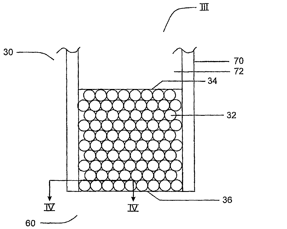
以下、図3について説明すると、図2で識別されたエレクトロスプレイエミッタ30のセクションIIIを示す。エレクトロスプレイエミッタ30は、封入粒子32を含む容器70をさらに備えることが示されている。容器70はチャネル72を備え、放出端60に封入粒子32が充填されていることが示されている。封入粒子32は用途によって、チャネル72全てを満たすことができる。粒子は下記重合過程によりポリママトリクスにより封入される。封入粒子は試料ローディング表面34および放出表面36を有する。ペプチドおよび/またはタンパク質などの成分を含む試料を、当技術分野において公知の様々な方法、例えばシリンジポンプまたは他のポンプにより液絡部35を介して、チャネル72を通して、試料ローディング表面34に移動させることができる。エレクトロスプレイエミッタ30は必ずしも試料を変化させる(すなわち、試料の成分の相対濃度を変化させる)ために使用されるわけではない。試料は、受理されたまま放出されてもよく、および/または、当技術分野で公知の方法により、高速または高圧液体クロマトグラフィー(HPLC)、ナノ液体クロマトグラフィー(ナノLC)、またはキャピラリー電気泳動(CE)から直接来てもよい。
In the following, referring to FIG. 3, section III of the
試料溶液体積は変動するが、約50〜約5000nLの範囲、より好ましくは約100〜約3000nLの範囲、最も好ましくは約200〜約1000nLの範囲である。試料溶液中の成分は約1.0×10⁻¹⁸M〜約1.0×10⁻²M、より好ましくは1.0×10⁻¹⁶M〜約1.0×10⁻⁴M、最も好ましくは1.0×10⁻¹⁵M〜約1.0×10⁻⁶Mの濃度としてもよい。ローディング流速は約200〜約5000nL/分の範囲とすることができる。 The sample solution volume varies but is in the range of about 50 to about 5000 nL, more preferably in the range of about 100 to about 3000 nL, and most preferably in the range of about 200 to about 1000 nL. The components in the sample solution are about 1.0 × 10 −18 M to about 1.0 × 10 −2 M, more preferably 1.0 × 10 −16 M to about 1.0 × 10 −4 M, most preferably 1.0 × 10 −15 M to The concentration may be about 1.0 × 10 −6 M. The loading flow rate can range from about 200 to about 5000 nL / min.
試料は、シリンジポンプ、HPLCポンプまたはナノLCポンプなどの供給源から提供される流体力により試料ローディング表面34から放出表面36まで流れる。電気浸透流(EOF)実験の場合、溶液の電気浸透流から流れが生じる。
The sample flows from the
本発明の適した流速には、約10〜約10000nL/分の範囲、より好ましくは約50〜約1500nL/分の範囲、最も好ましくは約200〜約1000nL/分の範囲の速度が含まれる。 Suitable flow rates of the present invention include rates in the range of about 10 to about 10,000 nL / min, more preferably in the range of about 50 to about 1500 nL / min, and most preferably in the range of about 200 to about 1000 nL / min.
本発明の封入粒子32に印加される圧力としては、約20〜約8000psiの範囲、より好ましくは約100〜約4000psiの範囲、最も好ましくは約300〜約1500psiの範囲の圧力が含まれる。
The pressure applied to the encapsulated
溶液を封入粒子を通してポンピングするのに使用する圧力量は、組成物を通る経路長、すなわち、試料が通過する封入粒子の量に比例する。一般的には、経路が長いほど、圧力が高い。 The amount of pressure used to pump the solution through the encapsulated particles is proportional to the path length through the composition, ie, the amount of encapsulated particles that the sample passes through. In general, the longer the path, the higher the pressure.
放出端60の適した内径および外径には、約100〜約5000μmの範囲の外径および約5〜約2500μmの範囲の内径が含まれ、より好ましくは、外径が約100〜約3000μmの範囲であり、および内径が約20〜約100μmの範囲のであり、最も好ましくは外径が約150〜約360μmの範囲であり、および内径が約30〜約75μmの範囲である。放出表面36の表面積は、キャピラリーの内径内の全域に及ぶ。
Suitable inner and outer diameters of the
本明細書で使用されるように、「粒子」という用語は球、例えば、微小球または任意のサイズの球、ビーズ、立方体、および概長方形または不規則形状の他の3次元構造、などを示し、一般に、市販されているが、使用する前に改良してもよい。粒子は、金属酸化物、例えば、酸化鉄、無機酸化物、シリカ、アルミナ、チタニアおよびジルコニア、化学的に結合された無機酸化物、例えば有機シロキサン結合相、ヒドロシラン処理/ヒドロシル化結合相、ポリマコート無機酸化物または金属酸化物、多孔質ポリマ、例えばスチレン-ジビニルベンゼンコポリマー、ポリオレフィン、例えばポリアクリレート、ポリメタクリレート、およびポリスチレンなどの材料基材を含んでもよい。粒子は、例えば、オクタデシルシラン(ODS)粒子、アガロースビーズ、フッ素化ビーズ、およびシリカ系粒子を含んでもよい。粒子は多孔性、メソ多孔性、もしくは非多孔性、またはそれらの組み合わせであってもよい。多孔性またはメソ多孔性粒子は、直径約100Å未満、直径約100〜約300Å、もしくは直径が約300Åを越える、またはそれらの組み合わせの細孔を有してもよい。 As used herein, the term “particle” refers to spheres, such as microspheres or spheres of any size, beads, cubes, and other three-dimensional structures of generally rectangular or irregular shapes, etc. Generally, it is commercially available, but may be improved before use. The particles may be metal oxides such as iron oxide, inorganic oxides, silica, alumina, titania and zirconia, chemically bonded inorganic oxides such as organosiloxane bonded phases, hydrosilane treated / hydrosilated bonded phases, polymer coats Material substrates such as inorganic oxides or metal oxides, porous polymers such as styrene-divinylbenzene copolymers, polyolefins such as polyacrylates, polymethacrylates, and polystyrene may be included. The particles may include, for example, octadecylsilane (ODS) particles, agarose beads, fluorinated beads, and silica-based particles. The particles may be porous, mesoporous, or nonporous, or a combination thereof. The porous or mesoporous particles may have pores that are less than about 100 mm in diameter, about 100 to about 300 mm in diameter, or greater than about 300 mm in diameter, or combinations thereof.
粒子は任意で、粒子に所望の化学的特性、例えば親和性を付与する置換基を有してもよく、そのため、粒子はクロマトグラフィーに適している。置換基としては、例えば、ケトン基、アルデヒド基、カルボキシル基、例えば、カルボン酸、エステル、アミド、および酸ハロゲン化物基、クロロメチル基、シアヌル基、ポリグルタルアルデヒド基、エポキシド基、チオール基、アミン基、シラノール基、ヒドロキシル基、スルホン酸基、リン酸基、および/または非置換もしくは置換脂肪族もしくは芳香族炭化水素が挙げられる。例えば、逆相クロマトグラフィーでは、アルキル、フルオロアルキルおよびフェニル結合材料を添加してもよく;イオン交換クロマトグラフィーでは、スルホン酸、カルボン酸、四級アミン結合または他の材料を添加してもよく;サイズ排除クロマトグラフィーでは、グリセロール結合材料、多糖およびポリデキストランゲルを添加してもよく;アフィニティクロマトグラフィーでは、酵素、抗体、レクチン、および金属イオン固定材料を添加してもよい。例えば、粒子は、ヒスチジン基を有する分子を引きつけるようにニッケルを、またはグリコシル化部位を有するタンパク質を引きつけるようにレクチンを含んでもよい。 The particles may optionally have substituents that impart desired chemical properties, such as affinity, to the particles, so that the particles are suitable for chromatography. Substituents include, for example, ketone groups, aldehyde groups, carboxyl groups, such as carboxylic acids, esters, amides, and acid halide groups, chloromethyl groups, cyanuric groups, polyglutaraldehyde groups, epoxide groups, thiol groups, amines. Groups, silanol groups, hydroxyl groups, sulfonic acid groups, phosphoric acid groups, and / or unsubstituted or substituted aliphatic or aromatic hydrocarbons. For example, for reverse phase chromatography, alkyl, fluoroalkyl and phenyl linkage materials may be added; for ion exchange chromatography, sulfonic acid, carboxylic acid, quaternary amine linkages or other materials may be added; For size exclusion chromatography, glycerol binding materials, polysaccharides and polydextran gels may be added; for affinity chromatography, enzymes, antibodies, lectins, and metal ion immobilization materials may be added. For example, the particles may include nickel to attract molecules with histidine groups or lectins to attract proteins with glycosylation sites.
粒子は、クロマトグラフィーに適すように、化学的におよび/または物理的に修飾されてもよい。粒子がすでに、クロマトグラフィーに対し所望の化学的および/または物理的特性を有する場合、粒子を修飾せずに使用してもよい。 The particles may be chemically and / or physically modified to be suitable for chromatography. If the particles already have the desired chemical and / or physical properties for chromatography, the particles may be used without modification.
同じ粒子により、異なる条件、例えば異なる溶媒条件において異なる特性が証明される可能性がある。 The same particles can demonstrate different properties under different conditions, such as different solvent conditions.
粒子は磁性材料、例えば常磁性材料を含むことができ、そのため、光開始工程前に粒子を容器内に配置するのに磁石を使用することができる。この用途または他の用途に適した粒子としては金属酸化物コートポリオレフィン粒子、例えば酸化鉄-ポリスチレンまたは磁鉄鉱-ポリスチレン粒子が挙げられる。 The particles can comprise a magnetic material, such as a paramagnetic material, so that a magnet can be used to place the particles in the container prior to the photoinitiating step. Particles suitable for this or other applications include metal oxide coated polyolefin particles such as iron oxide-polystyrene or magnetite-polystyrene particles.
磁性粒子を含む粒子は、例えばペプシンでコートしてもよく、例えば、PMPE-4(常磁性ペプシンコート粒子、4μm、Kisker Biotech、Steinfurt、Germany)である。粒子はまた、例えば、アビジン、ストレプタビジン、アルブミン抗体、例えばヤギ抗マウスIgG、パパイン、タンパク質A、タンパク質G、PEG-COOH、またはPEG-NH2基などの基でコートしてもよい(そのような磁性粒子は全て、例えば、Kisker Biotech、Steinfurt、Germanyから入手可能)。 The particles containing magnetic particles may be coated with, for example, pepsin, for example PMPE-4 (paramagnetic pepsin coated particles, 4 μm, Kisker Biotech, Steinfurt, Germany). The particles may also be coated with groups such as, for example, avidin, streptavidin, albumin antibodies such as goat anti-mouse IgG, papain, protein A, protein G, PEG-COOH, or PEG-NH 2 groups (such as All magnetic particles are available, for example, from Kisker Biotech, Steinfurt, Germany).
本発明の1つの態様では、封入粒子を使用してタンパク質を消化することができる。この態様では、材料は、タンパク質を消化するのに使用される試薬、例えば、酵素、およびトリプシンなどの適した緩衝液に対し安定でなければならない。 In one embodiment of the invention, the encapsulated particles can be used to digest proteins. In this aspect, the material must be stable to the reagents used to digest the protein, eg, enzymes, and a suitable buffer such as trypsin.
粒子直径は約0.1〜約1000μmの範囲、より好ましくは約0.3〜約600μmの範囲、最も好ましくは約0.5〜約300μmの範囲としてもよい。特定用途に対してはより大きな粒子が考えられる可能性がある。 The particle diameter may range from about 0.1 to about 1000 μm, more preferably from about 0.3 to about 600 μm, and most preferably from about 0.5 to about 300 μm. Larger particles may be considered for specific applications.
ペプチド合成および/またはコンビナトリアル合成のために有用な粒子を本発明の別の態様に適用できることも企図される。この場合、ペプチド合成および/またはコンビナトリアル合成のための粒子を、容器、例えばカラムまたはキャピラリーに封入することができ、そのためフロースルー合成を実施することができる。様々な活性種が粒子および/または溶液の一部に付着し、例えば求核アミノ酸または活性エステルを有するアミノ酸である。また、あるいはさらに、溶液は連続合成用途では触媒層を通過することができる。そのような過程はまた、小分子合成またはポリヌクレオチド合成などの合成に適合させることができることは理解されると思われる。 It is also contemplated that particles useful for peptide synthesis and / or combinatorial synthesis can be applied to other embodiments of the invention. In this case, particles for peptide synthesis and / or combinatorial synthesis can be encapsulated in a container, such as a column or capillary, so that flow-through synthesis can be performed. Various active species are attached to the particles and / or part of the solution, for example amino acids with nucleophilic amino acids or active esters. Alternatively or additionally, the solution can pass through the catalyst layer for continuous synthesis applications. It will be appreciated that such a process can also be adapted for synthesis such as small molecule synthesis or polynucleotide synthesis.
封入粒子32は、化学的および/または物理的に注入試料成分と相互作用することにより機能することができる。そのような相互作用により、注入表面34から放出表面36まで注入した試料の成分の相対組成および/または特性が変化する可能性がある。
The encapsulated
粒子の表面化学は、「オフライン」で実施することができ、その後、装置またはキャピラリーに組み入れることができる。試料成分との起こりうる相互作用は、粒子が例えば、炭素18(C18)で官能化されている場合疎水相互作用、粒子が例えば、スルホン酸で官能化されている場合、親水および/または静電相互作用を含む。他の相互作用としては、粒子が、試料内の様々なサイズの成分と相互作用する様々なサイズの空洞または細孔を含み、サイズに基づき成分を分離する、サイズ排除相互作用が挙げられる。 The surface chemistry of the particles can be performed “offline” and then incorporated into a device or capillary. Possible interactions with sample components include hydrophobic interactions when the particles are functionalized with, for example, carbon 18 (C18), hydrophilic and / or electrostatic when the particles are functionalized with, for example, sulfonic acid. Includes interactions. Other interactions include size exclusion interactions in which the particles include cavities or pores of various sizes that interact with components of various sizes within the sample and separate the components based on size.
封入粒子32は、化学的または物理的に試料と全く相互作用する必要がなく、マイクロスプレイまたはナノスプレイとして試料を放出するための適したチャネルおよび/または細孔を提供するものとして機能するだけであってもよい(下記でさらに記載する)。
The encapsulated
エレクトロスプレイエミッタ30は容器70を備え、この容器は本発明による粒子の封入に適したキャピラリーであってもよい。別の適した格納容器としては、下記のようなマイクロチップの一部が挙げられる。ガラス、例えば溶融シリカキャピラリーが好ましい。市販の容器を受理したまま使用してもよく、またはレーザを用いて、または手作業で、ミクロトーチを用いて引っ張りそのサイズまたは形状を変化させるなどの技術により改良してもよい。十分な導電性のために、容器を導電性材料、例えば、金でスパッタコートしてもよく、または、薄い金属ワイヤをナノスプレイ質量分析システム20の動作中にキャピラリーに挿入してもよい。容器は、重合過程(下記)を誘導することができるようにU.V.光を通過させることができる材料で作製されるべきである。容器はガラス、例えば溶融シリカ、およびプラスチック、例えばポリメチルメタクリレート(PMMA)、ポリカーボネートなどを含む材料で作製してもよい。
The
組成物は、例えば、装置内の空隙、例えば微小デバイス内の空隙を含む任意の容器内で形成させてもよい。空隙は、例えば、立方空隙を含む任意の形状としてもよい。そのような組成物は原位置反応のために使用することができる。例えば、トリプシン酵素コート粒子を含む本発明の組成物は、微小デバイスの表面上の空隙またはリザーバ内で作製してもよい。この場合、空隙またはリザーバを消化ベッドとして使用してもよい。組成物は、粒子を空隙に入れ、その後、重合混合物と混合することにより作製してもよい。粒子が、重力または遠心力により、空隙の底に沈むと直ちに、組成物を光開始により形成させてもよい。そのような反応では、重合混合物と反応することができる酸素量を最小限に抑えることが望ましい。酸素曝露を最小に抑える1つの方法は、使用する前に溶媒を脱ガスすることである。固定組成物をその後、相当量の消化生成物が溶液に残るまで、適した量のタンパク質溶液に適した時間、曝露させることができる。消化産物を有する溶液をその後、当技術分野で公知の手段、例えばデカンテーションまたは吸引により除去してもよい。 The composition may be formed in any container including, for example, a void in the apparatus, such as a void in a microdevice. For example, the void may have any shape including a cubic void. Such compositions can be used for in situ reactions. For example, a composition of the invention comprising trypsin enzyme coated particles may be made in a void or reservoir on the surface of a microdevice. In this case, a void or reservoir may be used as a digestion bed. The composition may be made by placing the particles in voids and then mixing with the polymerization mixture. As soon as the particles sink to the bottom of the void by gravity or centrifugal force, the composition may be formed by photoinitiation. In such reactions, it is desirable to minimize the amount of oxygen that can react with the polymerization mixture. One way to minimize oxygen exposure is to degas the solvent before use. The fixing composition can then be exposed to a suitable amount of protein solution for a suitable time until a substantial amount of digestion product remains in solution. The solution with the digestion product may then be removed by means known in the art, such as decantation or aspiration.
粒子をポリマーにより容器内に封入させる。本発明により使用するのに適したポリマとしては、マトリクスを形成することができる任意のポリマまたはコポリマ混合物が挙げられる。マトリクスは、ポリオレフィン、例えばポリアクリレート、ポリメタクリレート、ポリスチレンなどを含む多孔質ポリマモノリスとしてもよい。また、マトリクスは実質的に非多孔質材料、例えば、ジメタクリレートを追加のポリマなしで重合させることにより作製した材料であってもよい。 The particles are encapsulated in a container with a polymer. Suitable polymers for use in accordance with the present invention include any polymer or copolymer mixture that can form a matrix. The matrix may be a porous polymer monolith comprising a polyolefin, such as polyacrylate, polymethacrylate, polystyrene, and the like. The matrix may also be a substantially non-porous material, such as a material made by polymerizing dimethacrylate without an additional polymer.
ポリマはモノマーをU.V.光に、適当な溶媒および光開始剤の存在下で曝露することにより形成できると好都合である。このように、容器の選択した部分のみ、例えばキャピラリーを重合過程に従わせてもよく、そうすると、容器の選択した部分のみが封入粒子を含む。未反応重合混合物を容器の選択していない部分から洗い流すことができる。この過程は、「光パターニング」と呼ばれる。 The polymer can be conveniently formed by exposing the monomer to U.V. light in the presence of a suitable solvent and photoinitiator. In this way, only selected portions of the container, eg, capillaries, may be subjected to the polymerization process, so that only selected portions of the container contain encapsulated particles. Unreacted polymerization mixture can be washed away from unselected parts of the container. This process is called “optical patterning”.
以下、図4について説明する、図3の線IV-IVに付いての断面図の走査電子顕微鏡写真を示す。図4は封入粒子および全体にわたる細孔またはチャネルを示す。これらの写真でわかるように、チャネル内に配置されたポリマはない。いくつかの接触点Pを円で囲む。発明者らは、本発明によるキャピラリーの端での粒子とのポリマー材料の光パターニングにより、適当な細孔サイズおよび疎水性表面特性を有する組成物が提供され、安定なエレクトロスプレイ過程が促進され、死容積の可能性およびキャピラリー閉塞の可能性の両方が減少することを発見した。また、光開始重合過程の結果として、本発明の組成物は、キャピラリーまた装置の特定領域で、再現性のある「細孔」または「チャネル」を有するように容易に形成させることができ、単一または複数のエレクトロスプレイプルームのいずれかが促進され、広い流速範囲にわたり安定したエレクトロスプレイが可能となる。光開始プロセスにより、ポリマは粒子の接触点間または粒子と容器の接触点間に配置されるにすぎない。 Hereinafter, a scanning electron micrograph of a cross-sectional view taken along line IV-IV in FIG. 3 will be described with reference to FIG. FIG. 4 shows the encapsulated particles and the entire pore or channel. As can be seen in these pictures, no polymer is placed in the channel. Surround several contact points P with a circle. The inventors have provided a composition with suitable pore size and hydrophobic surface properties by photopatterning of the polymer material with the particles at the end of the capillary according to the present invention, promoting a stable electrospray process, We have found that both the possibility of dead volume and the possibility of capillary blockage are reduced. Also, as a result of the photoinitiated polymerization process, the composition of the present invention can be easily formed to have reproducible “pores” or “channels” in a capillary or a specific region of the device, Either one or more electrospray plumes are promoted, allowing stable electrospray over a wide flow rate range. By the photoinitiation process, the polymer is only placed between the contact points of the particles or between the contact points of the particles and the container.
本発明の組成物による適したチャネル直径には、約0.2〜約30μmの範囲、より好ましくは約0.5〜約10μmの範囲、最も好ましくは約1.0〜約5.0μmの範囲の直径が含まれる。 Suitable channel diameters according to the compositions of the present invention include diameters in the range of about 0.2 to about 30 μm, more preferably in the range of about 0.5 to about 10 μm, and most preferably in the range of about 1.0 to about 5.0 μm.
放出端36のチャネル直径は粒子サイズにより制御してもよい。粒子はきっちりと充填されると、粒子間の空間はチャネルを形成し、これがエレクトロスプレイエミッタとして機能する。球が大きくなるほど、球間の空間が大きくなる。
The channel diameter at the
関連する技術分野の当業者には、全ての重合組成物または条件が全ての粒子と共に使用するのに適しているわけではないことが理解されると思われる。例えば、ポリスチレン系粒子、例えばポリスチレン球は、ある重合組成物の存在で膨潤する可能性がある。しかしながら、当業者は、必要以上の実験をしなくても、より親水性であるモノマーおよび溶媒条件を使用すると、ポリスチレン粒子の膨潤を減少させることができることを学んでいると考えられる。 It will be appreciated by those skilled in the relevant art that not all polymerization compositions or conditions are suitable for use with all particles. For example, polystyrene-based particles, such as polystyrene spheres, can swell in the presence of certain polymeric compositions. However, one skilled in the art would have learned that the more hydrophilic monomer and solvent conditions can be used to reduce the swelling of polystyrene particles without undue experimentation.
本発明の態様について、以下、実施例により説明する。本発明の範囲は本明細書で例示した特定の態様により制限されないことを理解すべきである。 Embodiments of the present invention will be described below with reference to examples. It should be understood that the scope of the present invention is not limited by the particular embodiments illustrated herein.
実施例1 ポリママトリクス中に封入させたシリカ粒子を組み入れた噴霧器の作製
1.1 材料および装置
紫外線(U.V)透過コーティングを備えた溶融シリカキャピラリー(内径約75μm、外径約363μm)を、Polymicro Technologies, L.L.C.(Phoenix, AZ, US)から入手した。Mineralight UVランプ、UVG-11 254nm (Upland, CA, US)を用いて重合を実施した。Harvard Apparatus 11プラスシリンジポンプ(Holliston, MA. US)を使用して液体を、キャピラリーまたはマイクロチップを通して誘導した。Nikon Eclipse ME600顕微鏡(東京、日本)を使用して、キャピラリーおよびマイクロチップチャネル内での粒子充填および重合をモニタした。走査電子顕微鏡(SEM)分析を、Jeol JSM-840走査顕微鏡(東京、日本)で実施した。実験は全て周囲温度で実施した。
Example 1 Preparation of a nebulizer incorporating silica particles encapsulated in a polymer matrix
1.1 Materials and Equipment Fused silica capillaries (inner diameter about 75 μm, outer diameter about 363 μm) with ultraviolet (UV) transparent coating were obtained from Polymicro Technologies, LLC (Phoenix, AZ, US). Polymerization was performed using a Mineralight UV lamp, UVG-11 254 nm (Upland, CA, US). The liquid was directed through a capillary or microchip using a Harvard Apparatus 11 plus syringe pump (Holliston, MA. US). A Nikon Eclipse ME600 microscope (Tokyo, Japan) was used to monitor particle packing and polymerization in capillaries and microchip channels. Scanning electron microscope (SEM) analysis was performed with a Jeol JSM-840 scanning microscope (Tokyo, Japan). All experiments were performed at ambient temperature.
ブチルアクリレートモノマーをAldrichから入手し、新しい活性アルミナを通して濾過し阻害剤を除去した。3-(トリメトキシシリル)プロピルメタクリレート、2-アクリルアミド-2-メチル-1-プロパンスルホン酸(AMPS)、1,3-ブタンジオールジアクリレート(BDDA)、およびベンゾインメチルエーテル(BME)をAldrichから入手し、受理したまま使用した。緩衝塩TrisはFisher Scientificから購入したが、トリシンはSigmaから入手した。緩衝液は、Milli-Qグラジエント水精製システム(Millipore S.A. Molsherim, France)を通して濾過した〜18.2MΩ・cm脱イオン水を用いて調製した。エタノールをCommercial Alcohols Inc. (Brampton, ON, Canada)から購入した。氷酢酸およびHPLCグレードアセトニトリルおよびメタノールをFisher Scientificから入手した。3マイクロメータ(μm)オクタデシルシラン(ODS)粒子Microsorb 100-3 C-18)をVarian Canada Inc.(Mississauga, ON, Canada)から贈り物として受理した。 Butyl acrylate monomer was obtained from Aldrich and filtered through fresh activated alumina to remove the inhibitor. 3- (Trimethoxysilyl) propyl methacrylate, 2-acrylamido-2-methyl-1-propanesulfonic acid (AMPS), 1,3-butanediol diacrylate (BDDA), and benzoin methyl ether (BME) from Aldrich And used as received. The buffer salt Tris was purchased from Fisher Scientific, while Tricine was obtained from Sigma. The buffer was prepared using ~ 18.2 MΩ · cm deionized water filtered through a Milli-Q gradient water purification system (Millipore S.A. Molsherim, France). Ethanol was purchased from Commercial Alcohols Inc. (Brampton, ON, Canada). Glacial acetic acid and HPLC grade acetonitrile and methanol were obtained from Fisher Scientific. Three micrometer (μm) octadecylsilane (ODS) particles Microsorb 100-3 C-18) were accepted as a gift from Varian Canada Inc. (Mississauga, ON, Canada).
全ての実験を、x-y-zステージおよびキャピラリーの位置決めを助けるための2つの電荷結合素子(CCD)カメラキットを備えたナノエレクトロスプレイ源(Proxeon, Odense, Denmark)が取り付けられたAPI 3000三連四重極質量分析計(MDS-Sciex, Concord, Canada)上で実施した。ミクロT字結合部(Scientific Products, Toronto, ON, Canada)を使用して溶液移動ライン、エレクトロスプレイキャピラリーおよびエレクトロスプレイ電圧を供給するのに必要な電極を結合させた。シリンジに分析する溶液を充填し、ミクロT字結合部の移動ラインに取り付けた。アセンブリ全体をx-y-zステージに固定し、キャピラリーを、CCDカメラの助けにより質量分析計の入口に誘導した。ほとんどの実験において、キャピラリーは質量分析計(MS)のオリフィスから約5mmに維持した。エレクトロスプレイ(ES)電圧を液絡部を通して、MS電源をミクロT字部内に挿入した白金電極に接続することにより供給した。 API 3000 triple quadrupole fitted with a nanoelectrospray source (Proxeon, Odense, Denmark) with two charge-coupled device (CCD) camera kits to help position xyz stage and capillary for all experiments Performed on a mass spectrometer (MDS-Sciex, Concord, Canada). A micro-T junction (Scientific Products, Toronto, ON, Canada) was used to couple the solution transfer line, the electrospray capillary, and the electrodes necessary to supply the electrospray voltage. The syringe was filled with the solution to be analyzed and attached to the movement line of the micro-T junction. The entire assembly was fixed to an x-y-z stage and the capillary was guided to the entrance of the mass spectrometer with the aid of a CCD camera. In most experiments, the capillary was maintained approximately 5 mm from the mass spectrometer (MS) orifice. An electrospray (ES) voltage was supplied through a liquid junction by connecting an MS power source to a platinum electrode inserted into the micro-T section.
1.2 ナノスプレイエミッタ作製
1.2.1 粒子保持フリット作製
ナノスプレイエミッタを、最初に出口フリットを作製することにより調製した。キャピラリーを3-(トリメトキシシリル)プロピルメタクリレートにより8時間処理し、キャピラリー壁にアンカーを提供した。この後、重合混合物をキャピラリーまたはマイクロチップチャネル内にシリンジポンプを用いて導入した。その後、キャピラリーまたはマイクロチップ全体を1.5mmのUV-透過キャピラリーまたはマイクロチップのみを露出したままにしてマスクした。露出領域を254nm U.V.光で1.5分照射することにより、重合反応を開始させた。
1.2 Fabrication of nanospray emitter
1.2.1 Particle-Retaining Frit Fabrication Nanospray emitters were prepared by first creating an exit frit. Capillaries were treated with 3- (trimethoxysilyl) propyl methacrylate for 8 hours to provide anchors on the capillary walls. After this, the polymerization mixture was introduced into the capillary or microchip channel using a syringe pump. The entire capillary or microchip was then masked with only the 1.5 mm UV-transmissive capillary or microchip exposed. The polymerization reaction was initiated by irradiating the exposed area with 254 nm UV light for 1.5 minutes.
1.2.2 粒子封入
フリット形成後、多孔質ポリママトリクス装置に封入させたODS粒子を、下記手順を用いて調製した。ODS粒子をキャピラリーまたはマイクロチップチャネルのいずれかに、スラリー充填法により導入し、この後、重合混合物をシリンジポンプにより、キャピラリーまたはマイクロチップチャネルに導入した。数カラム体積の重合混合物を、キャピラリーまたはマイクロチップチャネルを通過させ、特定の領域を約254nm U.V.光に約2分間曝露することにより充填ビーズを固定した。重合後、80:20 v/vのアセトニトリル/5mMトリス緩衝液、pH8の混合物をシリンジポンプまたはナノ-HPLCポンプによりキャピラリーカラムを通して流すことにより洗浄した。ビーズ封入領域のキャピラリーを切断することにより、保持フリットをその後、除去した。封入ビーズの断面を観察するために、短い長さのキャピラリーカラムを切断し、金でコートし、SEMにより観察した。結果を図4に示し、上に記載する。封入ビーズは本質的に安定であることがわかり、いったん封入されると、約1500ポンド/平方インチ「psi」を超える(>1500psi)圧力まで安定であり、噴霧器完全性の損失はなかった。噴霧器を3週間を超えて使用したが、性能の喪失はなかった。
1.2.2 After forming the particle-encapsulated frit, ODS particles encapsulated in a porous polymer matrix device were prepared using the following procedure. ODS particles were introduced into either the capillary or the microchip channel by a slurry filling method, and then the polymerization mixture was introduced into the capillary or microchip channel by a syringe pump. Several column volumes of the polymerization mixture were passed through a capillary or microchip channel and the packed beads were immobilized by exposing specific areas to about 254 nm UV light for about 2 minutes. After polymerization, the mixture was washed by flowing a mixture of 80:20 v / v acetonitrile / 5 mM Tris buffer,
1.3 予備エレクトロスプレイ性能
図5aは、総イオン電流(TIC)トレースを示す図であり、図5bは本発明のナノスプレイエミッタにより発生したエレクトロスプレイに対する質量スペクトルトレースを示す図である。O-(2-アミノプロピル)-O'-(2-メトキシエチル)プロピルプロピレングリコール500(PPG)試料のTICはかなり安定であり、たった約40フェムトモルの材料からかなりきれいな質量スペクトルが得られる。噴霧のために共溶媒(すなわち、アセトニトリル(ACN)および水)を使用する安定なTICトレースの他に、ナノスプレイエミッタは、水性試料を噴霧する際には、PPM充填キャピラリーよりもかなり良好に実施する。
1.3 Preliminary Electrospray Performance FIG. 5a shows a total ion current (TIC) trace, and FIG. 5b shows a mass spectral trace for electrospray generated by the nanospray emitter of the present invention. The TIC of the O- (2-aminopropyl) -O ′-(2-methoxyethyl) propylpropylene glycol 500 (PPG) sample is fairly stable, resulting in a fairly clean mass spectrum from only about 40 femtomole material. In addition to stable TIC traces that use co-solvents (i.e. acetonitrile (ACN) and water) for nebulization, nanospray emitters perform significantly better than PPM-filled capillaries when nebulizing aqueous samples. To do.
噴霧器を多くの異なる流速で、TCIトレースおよび関連する質量スペクトルを調べることにより試験した。エレクトロスプレイイオン化(ESI)は、非常に広い流速範囲で実施することができる。約1000nL〜約200nL/分の範囲の流速で、安定なTICトレースを生成する単一の安定なTaylor円錐が観察された。約200nL/分未満では、おそらく複数のTaylor円錐による「ミスト」により安定なTICシグナルが得られる。50nL/分未満では、トレースは著しくノイズが多くなったが、十分なイオンが依然として生成され、質量スペクトルを取得することができた。10nL/分でさえも、ロイシンエンケファリンの「きれいな」スペクトルが生成した。 The nebulizer was tested at many different flow rates by examining TCI traces and associated mass spectra. Electrospray ionization (ESI) can be performed over a very wide flow rate range. A single stable Taylor cone producing a stable TIC trace was observed at flow rates ranging from about 1000 nL to about 200 nL / min. Below about 200 nL / min, a stable TIC signal is probably obtained by “mist” with multiple Taylor cones. Below 50 nL / min, the trace was significantly noisy, but enough ions were still produced and mass spectra could be acquired. Even at 10 nL / min, a “clean” spectrum of leucine enkephalin was generated.
これらの最小流速でのエレクトロスプレイの生成により、質量分析計に結合されたマイクロ流体チップにおける本発明の組成物の使用の利点が示される。典型的には、電気浸透ポンピングを使用するマイクロ流体装置は約50nL/分流速未満を送達する。 The generation of electrospray at these minimum flow rates demonstrates the advantages of using the composition of the present invention in a microfluidic chip coupled to a mass spectrometer. Typically, microfluidic devices using electroosmotic pumping deliver less than about 50 nL / min flow rate.
実施例2 固相抽出(SPE)のための本発明の封入粒子
粒子の表面化学を利用すると、MS分析を支援する試料調製手順を実施することができる。本発明の態様の組成物の試料調製能力を証明するために、固相抽出実験を実施した。SPEプロトコルを示す概略図を図6に示す。封入粒子を有する容器を工程Aで示す。ペプチド試料を、水性試料から高い流速を使用して封入ODS粒子上で予備濃縮した(工程BおよびC)。その後、濃縮試料を少量のACNで溶離させた(工程D)。従来のナノスプレイキャピラリーに対する、封入粒子による光パターニングキャピラリーの利点は、流れをシステム内で数tL/分を超えるようにうまく増加させることができ、逆圧がほとんどないことである。このように、試料を封入粒子上に迅速に流し、その後、より強い溶離力溶媒により徐々に溶離させることができる。
Example 2 Utilizing the surface chemistry of the encapsulated particle particles of the present invention for solid phase extraction (SPE), a sample preparation procedure that supports MS analysis can be performed. In order to demonstrate the sample preparation capability of the composition of the present invention, solid phase extraction experiments were performed. A schematic diagram showing the SPE protocol is shown in FIG. A container with encapsulated particles is shown in step A. Peptide samples were pre-concentrated on encapsulated ODS particles using high flow rates from aqueous samples (Steps B and C). The concentrated sample was then eluted with a small amount of ACN (Step D). The advantage of photopatterning capillaries with encapsulated particles over conventional nanospray capillaries is that the flow can be successfully increased to over a few tL / min in the system and there is little back pressure. In this way, the sample can be quickly flowed over the encapsulated particles and then gradually eluted with a stronger eluting solvent.
図7aは、図6で示したプロトコルに従い、800nL/分の流速で噴霧器上に450nMロイシンエンケファリン試料をローディングした結果を示す図である。ローディングは異なる時間長で変動させ、その後、約70% ACNで溶離させた。60秒ローディング実験により、著しい濃縮係数が得られた。図7bは、約556m/zで測定した、噴霧器上にロードしたペプチド量と相対イオン強度の直線関係を示す。 FIG. 7a shows the results of loading a 450 nM leucine enkephalin sample onto a nebulizer at a flow rate of 800 nL / min according to the protocol shown in FIG. The loading was varied for different time lengths and then eluted with about 70% ACN. A 60 second loading experiment yielded a significant concentration factor. FIG. 7b shows the linear relationship between the amount of peptide loaded on the nebulizer and the relative ionic strength, measured at about 556 m / z.
図8は、約100%水溶液で噴霧器上にロードし、その後、約70% ACNで、異なる流速で溶離させた約50nLの4.6×10⁻⁹M試料(すなわち、240アトモル)のロイシンエンケファリン(A〜E)およびTIC(E)から誘導した質量スペクトル(F)の結果を示す図である。これにより、非常に少量のタンパク質が噴霧器上で濃縮され、その後のMS検出が容易になる可能性が証明された。 FIG. 8 shows that about 50 nL of a 4.6 × 10 −9 M sample (i.e., 240 attomoles) of leucine enkephalin (A) loaded on a nebulizer with about 100% aqueous solution and then eluted with about 70% ACN at different flow rates. FIG. 5 shows the results of mass spectra (F) derived from ˜E) and TIC (E). This proved that very small amounts of protein could be concentrated on the nebulizer, facilitating subsequent MS detection.
ODS機能化粒子を用いてSPEを実施したが、様々な表面化学を有する様々な市販の粒子を使用することができる。 Although SPE was performed with ODS functionalized particles, a variety of commercially available particles with different surface chemistries can be used.
実施例3 BODIPY(登録商標)による固相抽出実験
微量のBODIPY(登録商標)およびBODIPY(登録商標)FLを用いて一連の固相抽出(SPE)実験を実施した。キャピラリー内で作製させた本発明のこの態様の組成物は、別の2つの粒子固定技術(単一フリットを有する充填カラム、入口および出口フリットを有する充填カラム)よりも、再現性およびロバストネスの観点から良好な性能を示した。
Example 3 Solid Phase Extraction Experiments with BODIPY® A series of solid phase extraction (SPE) experiments were performed using a small amount of BODIPY® and BODIPY® FL. The composition of this embodiment of the invention made in a capillary is more reproducible and robust than the other two particle fixation techniques (packed column with a single frit, packed column with an inlet and outlet frit). Showed good performance.
3.1 装置および試薬
キャピラリーでのCEC実験は全て、レーザ誘導蛍光(LIF)検出器(励起約488nm、発光約520nm)を備えたBeckman Coulter P/ACE MDQキャピラリー電気泳動システム(Fullerton、CA、US)で実施した。UV-透過コーティングを有する溶融シリカキャピラリー(内径約75μm、外径約363nm)をPolymicro Technologies, L.I.,C.(Phoenix, AZ, US)から入手した。Mineralight UVランプ、UVG-11 254nm(Upland, CA, US)を用いて重合を実施した。Harvard Apparatus 11+シリンジポンプ(Holliston、MA、US)を使用して、液体を、キャピラリーを通して誘導した。Nikon Eclipse ME 600顕微鏡(東京、日本)を使用して、キャピラリー内での粒子充填および重合を検査した。走査電子顕微鏡(SEM)解析をJeol JSM-840走査顕微鏡(東京、日本)で実施した。実験は全て周囲温度で実施した。
3.1 All CEC experiments on the instrument and reagent capillaries were performed on a Beckman Coulter P / ACE MDQ capillary electrophoresis system (Fullerton, CA, US) equipped with a laser-induced fluorescence (LIF) detector (excitation about 488 nm, emission about 520 nm). Carried out. Fused silica capillaries (inner diameter about 75 μm, outer diameter about 363 nm) with UV-transmissive coating were obtained from Polymicro Technologies, LI, C. (Phoenix, AZ, US). Polymerization was carried out using a Mineralight UV lamp, UVG-11 254 nm (Upland, CA, US). Liquid was directed through the capillary using a Harvard Apparatus 11+ syringe pump (Holliston, MA, US). A Nikon Eclipse ME 600 microscope (Tokyo, Japan) was used to examine particle packing and polymerization within the capillary. Scanning electron microscope (SEM) analysis was performed with a Jeol JSM-840 scanning microscope (Tokyo, Japan). All experiments were performed at ambient temperature.
ブチルアクリレートモノマーをAldrichから入手し、新たな活性化アルミナを通して濾過し、阻害剤(モノメチルエーテルヒドロキノン)を除去した。3-(トリメトキシシリル)プロピルメタクリレート、3-メタクリルオキシプロピルトリメトキシシラン、2-アクリルアミド-2-メチル-1-プロパンスルホン酸(AMPS)、1,3-ブタンジオールジアクリレート(BDDA)、およびベンゾインメチルエーテル(BME)は全て、Aldrichから入手し、受理したまま使用した。緩衝液塩、トリスをFisher Scientificから購入し、トリシンをSigmaから入手した。緩衝液は、Milli-Q Gradient水精製システム(Millipore S.A. Molsheim, France)を通して濾過した-18.2 MS2・cm脱イオン水を用いて調製した。 Butyl acrylate monomer was obtained from Aldrich and filtered through fresh activated alumina to remove the inhibitor (monomethyl ether hydroquinone). 3- (trimethoxysilyl) propyl methacrylate, 3-methacryloxypropyltrimethoxysilane, 2-acrylamido-2-methyl-1-propanesulfonic acid (AMPS), 1,3-butanediol diacrylate (BDDA), and benzoin All methyl ether (BME) was obtained from Aldrich and used as received. Buffer salt, Tris was purchased from Fisher Scientific and Tricine was obtained from Sigma. The buffer was prepared using -18.2 MS2 cm deionized water filtered through a Milli-Q Gradient water purification system (Millipore S.A. Molsheim, France).
エタノールをCommercial Alcohols Inc. (Brampton, ON, Canada)から購入した。氷酢酸およびHPLCグレードアセトニトリルおよびメタノールをFisher Scientificから入手した。31.tm ODS 粒子(Microsorb 100-3 C18)をVarian Canada Inc.(Mississauga, ON, Canada)から贈り物として受理した。4,4-ジフルオロ-1,3,5,7,8-ペンタメチル-4-ボラ-3a,4a-ジアザ-(S)-インダセン(BODIPY493/503)および4,4-ジフルオロ-5,7-ジメチル-4-ボラ-3a,4a-ジアザ-s-インダセン-3-プロピオン酸(BODIPY(登録商標)FL)をMolecular Probes, Inc.(Eugene, OR, US)から購入した。 Ethanol was purchased from Commercial Alcohols Inc. (Brampton, ON, Canada). Glacial acetic acid and HPLC grade acetonitrile and methanol were obtained from Fisher Scientific. 31.tm ODS particles (Microsorb 100-3 C18) were accepted as a gift from Varian Canada Inc. (Mississauga, ON, Canada). 4,4-Difluoro-1,3,5,7,8-pentamethyl-4-bora-3a, 4a-diaza- (S) -indacene (BODIPY493 / 503) and 4,4-difluoro-5,7-dimethyl -4-Bora-3a, 4a-diaza-s-indacene-3-propionic acid (BODIPY® FL) was purchased from Molecular Probes, Inc. (Eugene, OR, US).
3.2 充填カラム作製
1つのフリットを有する充填カラム:
出口フリットを調製するために、短い長さの多孔質ポリマモノリスを、Ngolaら[S.M. Ngola, Y. Fintschenko, W.Y. ChoiおよびT.J. Shepodd, Anal. Chem., 73(2001)849]により前に記載された方法と同様に調製した。キャピラリー壁を最初に、ビニル基とグラフトさせることにより前処理し、これにより、形成したポリマーが確実に壁に供給結合されるようにし;キャピラリーを3-メタクリルオキシプロピルトリメトキシシラン(約20%、量は全て、特に記載がなければ体積%である)、氷酢酸(約30%)、および脱イオン水(約50%)で充填し、12時間反応させ、その後、洗浄し、エタノール(約20%)、アセトニトリル(約60%)、および5mMリン酸緩衝液、pH6.8(約20%)を含む溶液中で保存した。約23%のブチルアクリレートモノマー、架橋剤としての約10% BDDA、電気浸透流を保持するための約0.2%のAMPS、追加の接着促進剤としての約0.1%の3-メタクリルオキシプロピルトリメトキシシラン、開始剤としての約0.2%(g/ml)のBME、約13.25%のエタノール、約40%のアセトニトリル、および細孔形成溶媒としての約13.25%の5mMリン酸緩衝液、pH6.8を含む重合混合物を、シリンジポンプを使用してキャピラリー内に導入した。その後、キャピラリーをアルミニウム箔で覆い、約1.5mmのUV-透過キャピラリーを254nm UV光に約1.5分間曝露させた。キャピラリー中に1つだけフリットを有する充填カラムを調製するために、アセトニトリル中の31.tm ODS粒子のスラリーをその後、圧力をかけてキャピラリー中に導入し(超音波浴に浸漬)、2cmの長さのカラムを作製した。
3.2 Preparation of packed column
Packed column with one frit:
A short length porous polymer monolith was previously described by Ngola et al. [SM Ngola, Y. Fintschenko, WY Choi and TJ Shepodd, Anal. Chem., 73 (2001) 849] to prepare the outlet frit. Prepared in the same manner as described above. The capillary wall is first pretreated by grafting with vinyl groups, thereby ensuring that the formed polymer is feed bonded to the wall; the capillary is 3-methacryloxypropyltrimethoxysilane (about 20%, All amounts are by volume unless otherwise noted), filled with glacial acetic acid (about 30%), and deionized water (about 50%), reacted for 12 hours, then washed and ethanol (about 20%). %), Acetonitrile (about 60%), and 5 mM phosphate buffer, pH 6.8 (about 20%). About 23% butyl acrylate monomer, about 10% BDDA as a crosslinker, about 0.2% AMPS to retain electroosmotic flow, about 0.1% 3-methacryloxypropyltrimethoxysilane as an additional adhesion promoter About 0.2% (g / ml) BME as an initiator, about 13.25% ethanol, about 40% acetonitrile, and about 13.25% 5 mM phosphate buffer, pH 6.8, as a pore-forming solvent. The polymerization mixture was introduced into the capillary using a syringe pump. The capillary was then covered with aluminum foil and an approximately 1.5 mm UV-transmissive capillary was exposed to 254 nm UV light for approximately 1.5 minutes. To prepare a packed column with only one frit in the capillary, a slurry of 31.tm ODS particles in acetonitrile was then introduced into the capillary under pressure (immersed in an ultrasonic bath) and 2 cm long Sano column was produced.
2つの保持フリットを有する充填カラム:
出口フリットおよび2cmの長さのカラムを作製した後、重合混合物を再び、シリンジポンプによりキャピラリー中に導入した。数カラム体積の重合混合物を通過させた後、キャピラリーをアルミニウム箔で覆い、充填粒子のちょうど開端のキャピラリーの約1.5mmの領域を254nm UV光に約1.5分間曝露させた。その後、シリンジポンプを用いて、80:20v/vアセトニトリル/5mMトリス緩衝液、pH8の混合物を、カラムを通して流し、残留モノマ材料および細孔形成溶媒を除去した。
Packed column with two holding frit:
After making the outlet frit and the 2 cm long column, the polymerization mixture was again introduced into the capillary by syringe pump. After passing several column volumes of the polymerization mixture, the capillaries were covered with aluminum foil and an approximately 1.5 mm area of the capillary just at the open end of the packed particles was exposed to 254 nm UV light for approximately 1.5 minutes. Then, using a syringe pump, a mixture of 80:20 v / v acetonitrile / 5 mM Tris buffer,
3.3 封入カラム作製
多孔質ポリママトリクス中に封入させたODS粒子を有するキャピラリーを、下記手順を用いて調製した。出口フリットを構築した後、ODS粒子をスラリー充填法によりキャピラリー中に導入し、約2cmの長さのカラムを得た。重合混合物をシリンジポンプで再びキャピラリー中に導入した。数カラム体積の重合混合物をキャピラリーに通し、充填ビーズを、2cmの充填領域を254nm UV光に約2分間曝露することにより固定させた。その後、約80:20 v/vのアセトニトリル/5mMトリス緩衝液、pH8の混合物を、キャピラリーカラムを通してシリンジポンプにより流し、未反応モノマ材料および細孔形成溶媒を除去した。カラムベッドの断面を観察するために、セラミックカッタで短い長さのキャピラリーカラムを切断し、デシケーター内で乾燥させ、全ての水および溶媒を除去した。その後、試料を金でスパッタコートした後、走査電子顕微鏡で断面画像を取得した。
3.3 Preparation of Encapsulated Column A capillary having ODS particles encapsulated in a porous polymer matrix was prepared using the following procedure. After constructing the outlet frit, ODS particles were introduced into the capillary by a slurry filling method to obtain a column having a length of about 2 cm. The polymerization mixture was again introduced into the capillary with a syringe pump. Several column volumes of the polymerization mixture were passed through the capillary and the packed beads were fixed by exposing a 2 cm packed area to 254 nm UV light for about 2 minutes. Thereafter, a mixture of about 80:20 v / v acetonitrile / 5 mM Tris buffer,
3.4 固相抽出
2つの分析物を選択し、上記カラムを用いた固相抽出を証明した。0.10mMのBODIPY493/503およびBODIPY(登録商標)FL原液をHPLCグレードメタノール中で調製し、その後、10mMトリシン緩衝液、pH8中で所望の濃度まで希釈した。
3.4 Solid phase extraction
Two analytes were selected to demonstrate solid phase extraction using the column. 0.10 mM BODIPY493 / 503 and BODIPY® FL stock solutions were prepared in HPLC grade methanol and then diluted to the desired concentration in 10 mM Tricine buffer,
SPEを3工程で実施した。第1に、希釈試料を圧力を用いてクロマトグラフィーベッド上にロードした。第2に、水性緩衝液を、キャピラリーを通して流し、キャピラリー内のカラム上に残っている試料を洗浄した。ベッド上に保持された分析物をその後、80%のアセトニトリルを含む水性緩衝液で溶離した。BODIPYおよびBODIPY(登録商標)FLの蛍光を、クロマトグラフィーベッドのちょうど下流に配置したBeckman P/ACE MDQ CEのLIF検出システム(励起488nm、発光520nm)で検出した。各抽出間に、水性緩衝液ですすぐことにより装置を平衡化し、その後、新たにローディング工程を開始した。 SPE was performed in 3 steps. First, the diluted sample was loaded onto the chromatography bed using pressure. Second, an aqueous buffer was flowed through the capillary to wash the sample remaining on the column in the capillary. The analyte retained on the bed was then eluted with an aqueous buffer containing 80% acetonitrile. BODIPY and BODIPY® FL fluorescence was detected with a Beckman P / ACE MDQ CE LIF detection system (excitation 488 nm, emission 520 nm) located just downstream of the chromatography bed. Between each extraction, the apparatus was equilibrated by rinsing with an aqueous buffer, after which a new loading process was started.
3.5 破過曲線
SPEベッドの総容量を決定するために、10nMのBODIPYおよびBODIPY(登録商標)FL染料溶液を用いて、これらを個々に、水性緩衝液で平衡化したキャピラリーカラム上に注入することにより破過曲線を得た。BODIPYおよびBODIPY(登録商標)FLの蛍光シグナルを、LIF検出器を用いてベッドのちょうど下流で記録した(励起488nm、発光520nm)。
3.5 Breakthrough curve
To determine the total volume of the SPE bed, breakthrough curves were generated by injecting them individually onto capillary columns equilibrated with aqueous buffer using 10 nM BODIPY and BODIPY® FL dye solutions. Obtained. BODIPY and BODIPY® FL fluorescence signals were recorded just downstream of the bed using a LIF detector (excitation 488 nm, emission 520 nm).
3.6 結果
ブチルアクリレート、BDDAおよびAMPS溶液のUV光重合では、完了するまで室温で数分しか必要ではなく、熱重合に比べカラム作製時間が減少する。別の利点は、適当なマスキングにより容易に材料のパターニングが可能なことである。
3.6 Results UV photopolymerization of butyl acrylate, BDDA and AMPS solutions requires only a few minutes at room temperature to complete, reducing column preparation time compared to thermal polymerization. Another advantage is that material can be easily patterned by appropriate masking.
試料調製過程により、粒子がキャピラリー表面上に散乱した。対照的に、有機ポリマにより封入されたODS粒子は、キャピラリー切断後にも「充填された」ままであった(図4で示されるように)。有機ポリママトリクスが、どちらも互いに「接着」されたビーズ間で観察され、ビーズをキャピラリー壁に固定した。ビーズ-ビーズおよびビーズ-キャピラリー接触点でのポリマの形成は、おそらく、これらの領域で表面エネルギーが最小となることに起因する。 During the sample preparation process, particles were scattered on the capillary surface. In contrast, ODS particles encapsulated by organic polymer remained “filled” after capillary cutting (as shown in FIG. 4). An organic polymer matrix was observed between the beads, both “adhered” to each other, fixing the beads to the capillary wall. The formation of polymers at the bead-bead and bead-capillary contact points is probably due to minimal surface energy in these regions.
封入ビーズの機械強度を試験するために、出口フリットのない0.5cmの長さのベッドを作製し、HPLCポンプにより発生する最大圧力である4,400psiを超える圧力に耐えることを見出した。高い強度は、ビーズが互いに、およびキャピラリー表面に共有結合により付着されていることに起因する。結果として、充填キャピラリーは、ほとんどの高圧力クロマトグラフィー用途および電気クロマトグラフィー用途に対し十分なロバスト性を有するべきである。 To test the mechanical strength of the encapsulated beads, a 0.5 cm long bed without exit frit was made and found to withstand pressures exceeding 4,400 psi, the maximum pressure generated by the HPLC pump. The high strength is due to the beads being covalently attached to each other and to the capillary surface. As a result, packed capillaries should have sufficient robustness for most high pressure and electrochromatographic applications.
異なる方法を用いて調製したODSカラムのSPE能力を証明するために、BODIPYの希薄溶液をそれらのカラム上で濃縮させた。BODIPYは、水性環境でODS粒子に対し強い親和性を示す高親水性染料であり、520nmで強い蛍光発光を提供し、そのため、異なる型のカラムのSPE特性を調べるための開始分析物として選択した。 To demonstrate the SPE ability of ODS columns prepared using different methods, dilute solutions of BODIPY were concentrated on those columns. BODIPY is a highly hydrophilic dye that exhibits a strong affinity for ODS particles in an aqueous environment and provides strong fluorescence emission at 520 nm, so it was chosen as the starting analyte to investigate the SPE characteristics of different types of columns .
1つのフリットを用いて保持させたODSビーズは、充填ベッドの開端によりクロマトグラフィー材料の移動が可能となったため、再生不可能なSPE特性を示した。2つの保持フリットを有する充填ベッドは、最初の数日の使用では再生可能であったが、再現性はさらに動作させると徐々に劣化した。4日使用した後、溶離分析物の積分ピーク面積の相対標準偏差(RSD)は4.8%から6.2%に増加し、ピーク面積対試料ローディング時間の線形回帰のR2は0.9816から0.8479まで減少した。これは、カラム内での空隙形成にいたる粒子の蓄積移動によるものである。対照的に、封入カラムは、SPE実験でより良好な再現性を示した。溶離分析物の積分ピーク面積のRSDは5日の使用後4.2%に維持され、一方、ピーク面積対試料ローディング時間の線形回帰のR2は0.9934で維持された。これは再び、有機ポリマが充填粒子を定位置に固定し、移動を阻止したためと考えられ、強固な連続抽出ベッドが得られた。 ODS beads held with one frit showed non-reproducible SPE properties because the chromatographic material could be moved by the open end of the packed bed. A packed bed with two retaining frits was reproducible for the first few days of use, but the reproducibility gradually deteriorated upon further operation. After 4 days of use, the relative standard deviation (RSD) of the integrated peak area of the eluted analyte increased from 4.8% to 6.2% and the R 2 of the linear regression of peak area versus sample loading time decreased from 0.9816 to 0.8479. This is due to the accumulation and movement of particles leading to void formation in the column. In contrast, the enclosed column showed better reproducibility in SPE experiments. The RSD of the integrated peak area of the eluted analyte was maintained at 4.2% after 5 days of use, while the R 2 of the linear regression of peak area versus sample loading time was maintained at 0.9934. This was again thought to be because the organic polymer fixed the packed particles in place and prevented the migration, and a strong continuous extraction bed was obtained.
図9aは封入カラム上での10nM BODIPY試料に対する予備濃縮実験を示す。水性緩衝液を用いたベッド平衡化後、希薄試料を圧力によりベッド上にロードさせた。水性緩衝液による5分のすすぎ工程後、約80%のアセトニトリルを含む水性緩衝液を使用して、ベッドからEOFおよび圧力を用いて予備濃縮したBODIPYを溶離させた。BODIPYは有機溶媒溶離工程中、かなり狭いバンドで溶離され、水性緩衝液洗浄工程中、分析物は洗い流されず、理想的なSPE過程が示された。異なる試料ローディング時間および異なる試料濃度を用いた2つの実験を実施し、封入カラムの特性を調べた。22〜99秒の範囲の予備濃縮時間を用いると、予備濃縮時間に対しプロットしたピーク面積から、直線関係が得られた(R2=0.9978)(図9[[挿入図]]bで示す)。異なる濃度の試料(20〜140nM)を使用した実験では、試料濃度に対しプロットしたピーク面積では直線関係が得られた(R2=0.9890)(図10で示す)。 FIG. 9a shows a preconcentration experiment for a 10 nM BODIPY sample on an enclosed column. After bed equilibration with aqueous buffer, dilute samples were loaded onto the bed by pressure. After a 5 minute rinse step with aqueous buffer, an aqueous buffer containing about 80% acetonitrile was used to elute the preconcentrated BODIPY from the bed using EOF and pressure. BODIPY eluted with a fairly narrow band during the organic solvent elution process, and during the aqueous buffer wash process, the analyte was not washed away, indicating an ideal SPE process. Two experiments with different sample loading times and different sample concentrations were performed to characterize the enclosed column. Using a preconcentration time range of 22-99 seconds, a linear relationship was obtained from the peak area plotted against the preconcentration time (R 2 = 0.9978) (shown in Figure 9 [[inset]] b) . In experiments using different concentrations of samples (20-140 nM), a linear relationship was obtained for the peak area plotted against the sample concentration (R 2 = 0.9890) (shown in FIG. 10).
図11は希薄10pM BODIPY試料溶液を用いた予備濃縮実験を示す。トレースAは、15分間(1.77×10⁻¹⁷モル)注入した10pM BODIPY試料(80%アセトニトリル/20%水性緩衝液)に対する得られた検出シグナルを示す。検出領域に入った試料から得られた蛍光の増加が、「a」で見ることができ、試料が検出領域を通過した後に得られた蛍光の対応する減少が「b」で見ることができる。対照的に、トレースBは封入カラム上での15分の試料予備濃縮後に溶離させたピークを示す。予備濃縮係数は、希薄試料体積を、溶離/濃縮試料を含む溶離剤体積で割ることにより計算することができる。試料ローディングおよび溶離は両方共同じ圧力で実施するので、予備濃縮係数は希薄試料ローディング時間の溶離したBODIPYのピーク幅に対する比率に等しい。この実験では、得られた予備濃縮係数は44であった。 FIG. 11 shows a preconcentration experiment using a dilute 10 pM BODIPY sample solution. Trace A shows the resulting detection signal for a 10 pM BODIPY sample (80% acetonitrile / 20% aqueous buffer) injected for 15 minutes (1.77 × 10 −17 mol). The increase in fluorescence obtained from the sample entering the detection region can be seen at “a” and the corresponding decrease in fluorescence obtained after the sample has passed through the detection region can be seen at “b”. In contrast, Trace B shows a peak that elutes after 15 minutes of sample preconcentration on an enclosed column. The preconcentration factor can be calculated by dividing the dilute sample volume by the eluent volume containing the eluted / enriched sample. Since sample loading and elution are both performed at the same pressure, the preconcentration factor is equal to the ratio of the dilute sample loading time to the peak width of the eluted BODIPY. In this experiment, the resulting preconcentration factor was 44.
BODIPY(登録商標)FLは、その化学構造中のカルボン酸基のために、BODIPYよりも親水性である。BODIPYと同じ破過実験条件では、10nM BODIPY(登録商標)FLは迅速で、急な破過を示し(図12、トレースC)、一方、10nM BODIPY、pH8では顕著な破過は観察されなかった(図12、トレースA)。BODIPY(登録商標)FL上のカルボン酸基は約4〜5のpKaを有するので、pH8で部分的に脱プロトン化される。溶液のpHを減少させることにより、BODIPY(登録商標)FLはプロトン化され、より疎水性となった。そのため、pH3.2での22分破過実験で、平らなベースライン様蛍光シグナルにより示されるようにODSビーズの表面上によりしっかりと吸着される(図12、トレースB)。
BODIPY® FL is more hydrophilic than BODIPY because of the carboxylic acid group in its chemical structure. Under the same breakthrough experimental conditions as BODIPY, 10nM BODIPY® FL showed rapid breakthrough (Figure 12, Trace C), whereas no significant breakthrough was observed with 10nM BODIPY, pH8. (Figure 12, Trace A). Since the carboxylic acid group on BODIPY® FL has a pKa of about 4-5, it is partially deprotonated at
pH 8.0でのBODIPY(登録商標)FLのSPE実験では、BODIPY(登録商標)FLは水性緩衝液洗浄工程中に部分的に洗い流されることが観察された(図13A)。しかしながら、これらの非最適化SPE条件であっても、予備濃縮時間に対しプロットした有機溶媒溶離工程中のBODIPY(登録商標)FLのピーク面積は依然として、研究条件にわたり直線関係を提供し(R2=0.9941)(図13B)、この有機ポリマ封入ODSビーズカラムの抽出特性は予測可能であり、信頼できることが示された。 In SOD experiments with BODIPY® FL at pH 8.0, it was observed that BODIPY® FL was partially washed away during the aqueous buffer wash step (FIG. 13A). However, even with these non-optimized SPE conditions, the peak area of BODIPY® FL during the organic solvent elution step plotted against preconcentration time still provides a linear relationship across the study conditions (R 2 = 0.9941) (FIG. 13B), the extraction characteristics of the organic polymer-encapsulated ODS bead column were predictable and reliable.
実施例4 マイクロチップを用いた固相抽出
ロイシンエンケファリンのSPE実験を、マイクロチップ中で本発明の組成物を用い、Microfluidic Tool Kit(Micralyne, Edmonton, Canada)を使用して実施した。キットは、レーザ誘導蛍光(LIF)検出システム(670nmのバンドパスフィルタを備えた約635nmのダイオードレーザ)と結合させた高電圧電源を含んだ。ロイシンエンケファリンは約675nmでは蛍光発光を示さないので、0.1M 炭酸ナトリウム-重炭酸ナトリウム緩衝液、pH9.3に溶解したCy5蛍光染料により標識し、675nm LIF検出器で検出できるようにし、その後、希釈して、5mMのpH8リン酸緩衝液中で180nmol/Lとなるようにした。SPEを3工程で実施した。(1)希薄試料を、マイクロチップチャネルに横切って印加した約2.5kVの電力により発生させた電気浸透流(EOF)により、クロマトグラフィーベッド上にロードし、(2)水性緩衝液を、チャネルを通して流し、チャネル内のベッド上に残った試料を洗浄し、および(3)ベッド上に保持された分析物を、80%アセトニトリルを含む水性緩衝液で溶離した。Cy5標識ロイシンエンケファリンの蛍光を、クロマトグラフィーベッドのちょうど下流に配置したLIF検出システムで検出した。各抽出間で、装置を、水性緩衝液ですすぐことにより平衡化し、その後、新しいローディング工程を開始した。図14は、時間に対する蛍光強度のプロットを示し、180nM Cy5標識ロイシンエンケファリン試料に対する3工程予備濃縮実験における、ローディング、続いて、リン酸緩衝液フラッシュ、その後の80%アセトニトリルによる溶離中のCy5標識ロイシンエンケファリン試料の蛍光を示す。図14中のトレースは、より容易に見ることができるように、わずかに上方にオフセットさせている。異なる試料ローディング時間を使用して、抽出ベッドの特性を調べた。50〜200秒の範囲の予備濃縮では、予備濃縮時間に対する積分ピーク面積は直線関係を示した(R2=0.9769)。図15は、180nM Cy5標識ロイシンエンケファリンの蛍光強度のピーク面積対ローディング時間のグラフを示す。
Example 4 SPE experiments of solid phase extraction leucine enkephalin using a microchip were performed using the composition of the present invention in a microchip using the Microfluidic Tool Kit (Micralyne, Edmonton, Canada). The kit included a high voltage power supply coupled with a laser induced fluorescence (LIF) detection system (approximately 635 nm diode laser with a 670 nm bandpass filter). Leucine enkephalin does not emit fluorescence at approximately 675 nm, so it is labeled with Cy5 fluorescent dye dissolved in 0.1 M sodium carbonate-bicarbonate buffer, pH 9.3, so that it can be detected with a 675 nm LIF detector and then diluted. Then, it was adjusted to 180 nmol / L in 5
実施例5:マイクロ流体チップの調製
本発明の方法に従い、粒子をプラスチックまたはガラス微小デバイスの端に封入させる。図16は直接質量分析計中に噴霧させることができる微小デバイス100を示す。本発明の封入粒子32の光パターニングにより死容積の可能性が減少する。微小デバイスを極微走査装置に載置し、その後、質量分析計の前に配置する。ペプチドまたはタンパク質試料をリザーバ102中にロードし、その後、リザーバ102と104の間に電圧を供給し、試料をロードする。電圧および流体力学的流をリザーバ106に印加し、試料を質量分析計まで移動させる。エレクトロスプレイ過程のために電圧を使用する。
Example 5: Preparation of a microfluidic chip According to the method of the present invention, particles are encapsulated at the end of a plastic or glass microdevice . FIG. 16 shows a
実施例6:捕捉シリカ粒子(3μm)
直径約3μmのシリカ粒子を、実施例3.1〜3.3のODSビーズに対し一般的に記載したように捕捉させた。この実施例ではシリカ粒子を捕捉させるために、モノマ状態にいくらかの調整を実施し、より親水性の混合物を作製した。これは、スルホン酸成分をモノマ混合物の1〜40%まで増加することにより達成した。
Example 6: Captured silica particles (3 μm)
Silica particles about 3 μm in diameter were captured as generally described for the ODS beads of Examples 3.1-3.3. In this example, some adjustments were made to the monomer state to capture the silica particles to produce a more hydrophilic mixture. This was achieved by increasing the sulfonic acid component to 1-40% of the monomer mixture.
6.1 カラム調製
UV-透過コーティング(Polymicro Technologies Inc.)を有する溶融シリカキャピラリー(外径363μm、内径75μm)を、当業者に公知の方法により前処理した。その後、キャピラリー中で、前の封入手順と同様にフリットを調製した。
6.1 Column preparation
Fused silica capillaries (outer diameter 363 μm, inner diameter 75 μm) with UV-transmissive coating (Polymicro Technologies Inc.) were pretreated by methods known to those skilled in the art. A frit was then prepared in the capillary as in the previous encapsulation procedure.
最小表面被覆でシリカビーズを捕捉させるために、より親水性のモノマ溶液が必要であった。これは、スルホン酸の量を1〜40%まで増加させることにより達成した。この溶液は2mLの注型溶媒(1:1:3エタノール:緩衝液pH=7:アセトニトリル)、297μLのBDDA、3μLのz-6030、0.25gのAMPS、516μLのアクリル酸ブチルおよび5mgのベンゾイルメチルエーテルを含んだ。この溶液をキャピラリーを通して流し、ビーズを254ナノメートル(nm)の光を90秒間用いて封入させた。 A more hydrophilic monomer solution was required to capture the silica beads with minimal surface coverage. This was achieved by increasing the amount of sulfonic acid to 1-40%. This solution is 2 mL casting solvent (1: 1: 3 ethanol: buffer pH = 7: acetonitrile), 297 μL BDDA, 3 μL z-6030, 0.25 g AMPS, 516 μL butyl acrylate and 5 mg benzoylmethyl Ether was included. The solution was flowed through a capillary and the beads were encapsulated using 254 nanometer (nm) light for 90 seconds.
図17aは実施例6の方法により封入させたシリカ粒子を示す走査電子顕微鏡写真である。この図から、各粒子はほとんど、ポリマーにより被覆されていないことがわかる。図17bは2つの粒子間の架橋として作用するポリマーを示す。 FIG. 17a is a scanning electron micrograph showing silica particles encapsulated by the method of Example 6. FIG. From this figure, it can be seen that each particle is almost not covered with polymer. FIG. 17b shows the polymer acting as a crosslink between the two particles.
実施例7:モノマー無しでのODS粒子の捕捉
この実施例では、モノマーを含ませないことを除き、本明細書の実施例3で記載したプロトコルをこの実験のために使用した。架橋剤(BDDA)のみを用いてODSビーズが封入されるかどうかを決定するために、注型溶媒および開始剤を除く他の成分全てを系から除去した。この方法では、3.0mLの注型溶媒(1:1:3のエタノール:緩衝液pH=7:アセトニトリル)中のBDDA(300μL)を使用した。この溶液をODSビーズを含むキャピラリーを通して流し、重合を、254nm光を90秒間用いて開始させた。
Example 7: ODS particle capture without monomer In this example, the protocol described in Example 3 herein was used for this experiment, except that no monomer was included. All other components except the casting solvent and initiator were removed from the system in order to determine whether ODS beads were encapsulated using only crosslinker (BDDA). In this method, BDDA (300 μL) in 3.0 mL of casting solvent (1: 1: 3 ethanol: buffer pH = 7: acetonitrile) was used. This solution was flowed through a capillary containing ODS beads and polymerization was initiated using 254 nm light for 90 seconds.
図18aは、多くの場合、チャネルに至る閉塞されていない開口を有するビーズを示す走査電子顕微鏡写真を示す。金コーティングを使用し、SEMによりビーズを視認できるようにした。図18bから、モノマが重合混合物にたとえ添加されなくても、粒子間に架橋が存在することが示される。 FIG. 18a shows a scanning electron micrograph showing a bead with an unobstructed opening that often leads to a channel. A gold coating was used to make the beads visible by SEM. FIG. 18b shows that there is cross-linking between the particles even though no monomer is added to the polymerization mixture.
実施例8:ホルモンの固相抽出および分離
2つのホルモンの分離および固相抽出を証明するために実験を実施した。ホルモンは生体内で重要な生物学的効果を示す化合物の群である。しかしながら、生物分析または環境分析などの多くの実際の用途では、低い試料濃度が通常、これらの化合物の正確な検出および定量を妨げる。
Example 8: Solid phase extraction and separation of hormones
Experiments were performed to demonstrate the separation and solid phase extraction of the two hormones. Hormones are a group of compounds that exhibit important biological effects in vivo. However, in many practical applications, such as biological analysis or environmental analysis, low sample concentrations usually prevent accurate detection and quantification of these compounds.
この実験では、4ミリモル(mM)のβ-エストラジオールおよび5ミリモルのプロゲステロンの原液をHPLCグレードアセトニトリル(ACN)中で調製し、3ミリモルのトリシン緩衝液、pH7中で所望の濃度まで希釈した。固相抽出を3つの工程で、封入ODS粒子を含む6センチメートルの長さのカラム(Microsorb 100-3 C-18)上で実施した。第1に、希薄試料を動電学的にクロマトグラフィーベッド上にロードした。第2に、水性緩衝液を、電圧を印加することにより、キャピラリーを通ってカラム上まで流した。第3に、その後、ベッド上に保持された分析物を70% ACNを含む水性緩衝液によりEOFを用いて溶離させた。β-エストラジオールおよびプロゲステロンの紫外線吸光度を、クロマトグラフィーベッドの下流に配置したPDA(フォトダイオードアレイ)検出システムを用いて検出した。各抽出間に、水性緩衝液ですすぐことにより装置を平衡化し、その後、新規ローディング工程を開始した。
In this experiment, a stock solution of 4 mmol (mM) β-estradiol and 5 mmol progesterone was prepared in HPLC grade acetonitrile (ACN) and diluted to the desired concentration in 3 mmol Tricine buffer,
水性緩衝液によるベッド平衡化後、希薄試料を動電学的に、5キロボルトの電圧を5分間印加することによりベッド上にロードした。電圧を用いる水性緩衝液による6分のすすぎ工程後、70%のACNを含む水性緩衝液を使用して、予備濃縮したβ-エストラジオールおよびプロゲステロンをEOFを用いて溶離した。図19a、19bは、封入カラム上での、54.6マイクロモルのβ-エストラジオールおよび22.9マイクロモルのプロゲステロンを含む試料に対する予備濃縮実験結果を示す。点A前(0〜5分)は試料ローディングを示す。点A〜点B(5〜11分)の領域は、3ミリモルのトリシン緩衝液、pH7を用いた洗浄工程を示す。点B後(11〜23分)は、70% ACN/30% 10ミリモルトリシン緩衝液、pH7を用いた溶離工程を示す。有機溶媒溶離工程中に、かなり狭いピーク中に、β-エストラジオールおよびプロゲステロンが溶離され、分離され、希薄試料のピーク高さに比べるとβ-エストラジオールでは102、プロゲステロンでは82のシグナル増強が得られたことがわかる。
After bed equilibration with aqueous buffer, dilute samples were loaded on the bed electrokinetically by applying a voltage of 5 kilovolts for 5 minutes. After a 6-minute rinsing step with aqueous buffer using voltage, pre-concentrated β-estradiol and progesterone were eluted with EOF using an aqueous buffer containing 70% ACN. Figures 19a, 19b show the results of preconcentration experiments on a sample containing 54.6 micromoles β-estradiol and 22.9 micromoles progesterone on an enclosed column. Sample A is shown before point A (0-5 minutes). The region from point A to point B (5 to 11 minutes) represents a washing step using 3 mM Tricine buffer,
異なる試料ローディング時間で実施し、結果を図20に示す。図20は、6cmの封入3.0マイクロメートルODSカラム上での異なる長さの予備濃縮で得られたシグナル増強を示す。図から、シグナル増強対ローディング時間曲線は、10分後に非線形となり、最大シグナル増強はβエストラジオールに比べ、プロゲステロンに対しての方が大きいことがわかる。その差は、2つのホルモンの相対的な疎水性に起因する。β-エストラジオールはプロゲステロンよりも親水性であり、そのため、ODS粒子により、より低い程度で分配し、より速い溶離およびカラム飽和となる。SPE実験で使用した試料濃度は比較的高いが、これはPDA検出器の感度により制限され、600を超えるシグナル増強により封入ビーズカラムの有用性が示される。 The results are shown in FIG. 20 with different sample loading times. FIG. 20 shows the signal enhancement obtained with different lengths of preconcentration on a 6 cm enclosed 3.0 micrometer ODS column. The figure shows that the signal enhancement versus loading time curve becomes non-linear after 10 minutes and the maximum signal enhancement is greater for progesterone compared to β-estradiol. The difference is due to the relative hydrophobicity of the two hormones. β-estradiol is more hydrophilic than progesterone, so it is distributed to a lesser extent by ODS particles, resulting in faster elution and column saturation. The sample concentration used in the SPE experiments is relatively high, but this is limited by the sensitivity of the PDA detector, and the signal enhancement above 600 indicates the usefulness of the encapsulated bead column.
実施例9:芳香族多環式炭化水素(PAH)混合物の電気クロマトグラフィー
この実験は、16の芳香族多環式炭化水素、すなわち、ナフタレン、アセナフチレン、フルオレン、アセナフテン、フェナントレン、アントラセン、フルオランテン、ピレン、ベンゾ(a)アントラセン、クリセン、ベンゾ(b)フルオランテン、ベンゾ(k)フルオランテン、ベンゾ(a)ピレン、ジベンゾ(a,h)アントラセン、インデノ(1,2,3-cd)ピレンおよびベンゾ(ghi)ペリレンの電気クロマトグラフィーを示した。
Example 9: Electrochromatography of Aromatic Polycyclic Hydrocarbon (PAH) Mixture This experiment was performed with 16 aromatic polycyclic hydrocarbons, namely naphthalene, acenaphthylene, fluorene, acenaphthene, phenanthrene, anthracene, fluoranthene, pyrene. Benzo (a) anthracene, chrysene, benzo (b) fluoranthene, benzo (k) fluoranthene, benzo (a) pyrene, dibenzo (a, h) anthracene, indeno (1,2,3-cd) pyrene and benzo (ghi ) Electrochromatography of perylene was shown.
図21は、長さ6cmの封入3.0μmODSカラムを用いたEPA610PAH(Supelco of Bellefonte, Pennsylvania)混合物の254nmでのCECエレクトロフェログラムを示す。試料ローディング:2kV、3秒;溶離:10kV、80% ACN/20% 3mMトリシン緩衝液、pH8による;ピーク同定:1.チオ尿素(中性マーカー)、2.ナフタレン、3.アセナフチレン、4.フルオレン、5.アセナフテン、6.フェナントレン、7.アントラセン、8.フルオランテン、9.ピレン、10.ベンゾ(a)アントラセン、11.クリセン、12.ベンゾ(b)フルオランテン、13.ベンゾ(k)フルオランテン、14.ベンゾ(a)ピレン、15.ジベンゾ(a,h)アントラセン、16.インデノ(1,2,3-cd)ピレンおよび17.ベンゾ(ghi)ペリレン。
FIG. 21 shows a CEC electropherogram at 254 nm of a mixture of EPA610PAH (Supelco of Bellefonte, Pennsylvania) using a 6 cm long enclosed 3.0 μm ODS column. Sample loading: 2 kV, 3 seconds; Elution: 10 kV, 80% ACN / 20% 3 mM Tricine buffer,
この実験で使用したCE機器、Beckman Coulter P/ACE MDQはグラジエント溶離を実施することができないので、均一濃度溶離モードのみを分離で使用した。図21は、80%アセトニトリルにより、16PAH混合物から15ピークが分離できる(ベンゾ(a)アントラセンおよびクリセンはオーバーラップした)ことを示す。図22は、アセトニトリル濃度を70%まで低下させることにより達成された、最初の6つのかなり親水性の化合物の分離を示す。16の化合物のベースライン分離は取得しなかったが、使用した6cmのカラム長および均一濃度溶離モードを考慮すれば、この封入微小球カラムの分離能力は証明される。 Since the CE instrument, Beckman Coulter P / ACE MDQ, used in this experiment cannot perform gradient elution, only the uniform concentration elution mode was used for the separation. FIG. 21 shows that 80% acetonitrile can separate 15 peaks from the 16PAH mixture (benzo (a) anthracene and chrysene overlapped). FIG. 22 shows the separation of the first six fairly hydrophilic compounds achieved by reducing the acetonitrile concentration to 70%. A baseline separation of 16 compounds was not obtained, but the separation capability of this encapsulated microsphere column is demonstrated given the 6 cm column length and uniform concentration elution mode used.
図22は、長さ6cmの封入3.0μmODSカラムを用いたEPA610PAH混合物の254nmでのCECエレクトロフェログラムを示す。試料ローディング:2kV、3秒;溶離:5kVで最初に35分、その後10kV、70% ACN/30% 3mMトリシン緩衝液、pH8による;ピーク同定:1.チオ尿素(中性マーカー)、2.ナフタレン、3.アセナフチレン、4.フルオレン、5.アセナフテン、6.フェナントレン、7.アントラセン、8.フルオランテン、9.ピレン、10.ベンゾ(a)アントラセン、11.クリセン、12.ベンゾ(b)フルオランテン、13.ベンゾ(k)フルオランテン、14.ベンゾ(a)ピレン、15.ジベンゾ(a,h)アントラセン、および16.インデノ(1,2,3-cd)ピレン。
FIG. 22 shows a CEC electropherogram at 254 nm of an EPA610PAH mixture using a 6 cm long enclosed 3.0 μm ODS column. Sample loading: 2 kV, 3 seconds; Elution:
実施例10:複数のナノ噴霧器試験(単一バッチで調製した12のキャピラリー)
この実験で、複数の粒子封入容器を調製し、同時に使用することができることが証明された。1×10⁻⁶モルのPPG試料を12のキャピラリーの各々に注入し、結果をESI-MSにより分析した。試料を、一定注入法を用いてキャピラリー中に注入した。実験の詳細を下記で説明する。
Example 10: Multiple nano nebulizer tests (12 capillaries prepared in a single batch)
This experiment demonstrated that multiple particle enclosures can be prepared and used simultaneously. A 1 × 10 −6 mol PPG sample was injected into each of 12 capillaries and the results were analyzed by ESI-MS. The sample was injected into the capillary using a constant injection method. Details of the experiment are described below.
10.1:材料およびプロトコル
キャピラリー:UV透過、外径360μm、内径75μm
キャピラリー数:12(充填マニホルドを使用)
キャピラリーの総長:5.5cm(2つのキャピラリーはそれぞれ、4.5cmおよび4.7cmである)
ナノ粒子:3μmのODSビーズ(100Å)
固定ビーズ長:1.1cm
UV曝露時間:1.5分
UVランプからキャピラリーまでの距離:3.5cm
UVランプの電力:254nm、0.16AMPS
ポリプロピレングリコール(PPG)溶液の濃度:1×10⁻⁶M(溶媒:ACN)
ESI-MSのパラメータ
70% ACN流速:500nL/分
IS電圧:3kV
走査範囲:400〜1100amu
イオン抽出範囲:539.5〜541amu
10.1: Materials and protocols Capillary: UV transmission, outer diameter 360μm, inner diameter 75μm
Number of capillaries: 12 (uses a filling manifold)
Total capillary length: 5.5 cm (two capillaries are 4.5 cm and 4.7 cm, respectively)
Nanoparticles: 3μm ODS beads (100Å)
Fixed bead length: 1.1cm
UV exposure time: 1.5 minutes
Distance from UV lamp to capillary: 3.5cm
UV lamp power: 254nm, 0.16AMPS
Polypropylene glycol (PPG) solution concentration: 1 × 10 -6 M (solvent: ACN)
ESI-MS parameters
70% ACN flow rate: 500 nL / min
IS voltage: 3kV
Scanning range: 400-1100amu
Ion extraction range: 539.5 ~ 541amu
10.2:充填マニホルド
図23は、スケールアップ目的のために使用することができる、概して120で示した充填マニホルドの断面を示す図である。充填マニホルド120はボディ122を備える。ボディ122はカラムを規定する。ボディ122はさらに、キャピラリー入口128を介してカラム124と連結するフィッティング穴126を規定する。この実施例では、12のフィッティング穴126が、充填マニホルド120の1つの側で一般に規定されている。充填マニホルド120の周りで規定されているフィッティング穴(すなわち、全てが概して1つの側にあるわけではない)もまた、ある用途では適している可能性がある。充填マニホルド120はPEEK(ポリエーテルエーテルケトン)またはステンレス鋼などの任意の適した材料を含んでもよく、公知の方法、例えば、標準機械加工法またはCNC(コンピュータ数値制御)ミリングに従い製造してもよい。充填マニホルド120はさらに、チャネル132を介してカラム124と連結するカラム入口130を規定する。カラム入口130を粒子、溶媒、モノマ、光開始剤、および/または架橋剤などの材料をカラム124に添加するための進入点として使用する。プラグ134を一端に挿入し、材料がカラム124から漏れないようにする。カラム入口130は、材料をカラム124に送達するために使用される容器(図示せず)、例えば対応する螺旋模様を有するチューブと密閉嵌合するために、螺旋模様を有してもよい。動作中、フリットを有するキャピラリー(図示せず)をフィッティング穴の各々の中に挿入し、フェルールにより定位置に保持したが、任意の適した固定手段を使用することができる。粒子を重合溶媒中に懸濁させ、圧力によりカラム入口130を通ってカラム124内に、キャピラリー入口128を通ってキャピラリー中に移動させ、そこで、約1500psiの圧力で充填させた。その後、キャピラリーをマニホルドからはずし、光開始させ、上記試験で使用した。関連技術分野の当業者には理解されるであろうが、光開始過程はまた、キャピラリーをマニホルドに固定したまま実施することができる。
10.2: Fill Manifold FIG. 23 shows a cross section of the fill manifold, generally indicated at 120, that can be used for scale-up purposes.
10.3:結果
結果を図1に示す。PPGイオンの平均強度および標準偏差により、ポリマ封入粒子の使用は、製造においてスケールアップすることができ、再現性が実質的に喪失されないことが証明される。
10.3: The results are shown in Figure 1. The average intensity and standard deviation of the PPG ions demonstrates that the use of polymer encapsulated particles can be scaled up in manufacturing and reproducibility is not substantially lost.
実施例11:複数のナノ噴霧器試験(2つのキャピラリー)
この実験により、2つの異なるナノ噴霧器キャピラリーから放出されたPPGの1×10⁻⁶M試料の結果の再現性が証明された。実験の詳細を下記で説明する。
Example 11: Multiple nano nebulizer tests (2 capillaries)
This experiment demonstrated the reproducibility of the results for a 1 × 10 −6 M sample of PPG released from two different nano-atomizer capillaries. Details of the experiment are described below.
11.1:材料およびプロトコル
ナノ噴霧器試験
キャピラリー:UV透過、外径360μm、内径75μm
キャピラリー数:2
キャピラリーの総長:5.5cm
ナノ粒子:3μmのODSビーズ(100Å)
固定ビーズ長:1.1mm
UV曝露時間:1.5分
UVランプからキャピラリーまでの距離:3.5cm
UVランプの電力:254nm、0.16AMPS
PPG溶液の濃度:1×10⁻⁶M(溶媒:ACN)
ESI-MSのパラメータ
70% ACN流速:500nL/分
IS電圧:3kV
走査範囲:400〜1100amu
イオン抽出範囲:539.5〜541amu
逆圧:約30psi
11.1: Materials and protocols Nano nebulizer test capillary: UV transmission, outer diameter 360μm, inner diameter 75μm
Number of capillaries: 2
Total length of capillary: 5.5cm
Nanoparticles: 3μm ODS beads (100Å)
Fixed bead length: 1.1mm
UV exposure time: 1.5 minutes
Distance from UV lamp to capillary: 3.5cm
UV lamp power: 254nm, 0.16AMPS
Concentration of PPG solution: 1 × 10 -6 M (solvent: ACN)
ESI-MS parameters
70% ACN flow rate: 500 nL / min
IS voltage: 3kV
Scanning range: 400-1100amu
Ion extraction range: 539.5 ~ 541amu
Back pressure: about 30psi
11.2結果
図24aは、1つのエミッタから放出されたPPG(1×10⁻⁶M)の分析を示す539.5〜541の範囲の抽出イオンクロマトグラム(XIC)を示す。図24bは、エミッタにより発生させたPPG試料の即時エレクトロスプレイ質量スペクトルトレースを示す。表2は平均強度および結果の標準偏差を示す。
11.2 Results FIG. 24a shows an extracted ion chromatogram (XIC) ranging from 539.5 to 541 showing the analysis of PPG (1 × 10 −6 M) emitted from one emitter. FIG. 24b shows an immediate electrospray mass spectral trace of the PPG sample generated by the emitter. Table 2 shows the mean intensity and the standard deviation of the results.
実施例12:C-18ビーズサイズ、キャピラリーサイズおよび流速によるナノ噴霧器に対する最適化
表3のデータは、本発明による適したパラメータの選択を証明する。これらのデータを得るために使用した条件は実施例1で記載している。
Example 12: Optimization for nano-nebulizers by C-18 bead size, capillary size and flow rate The data in Table 3 demonstrates the selection of suitable parameters according to the present invention. The conditions used to obtain these data are described in Example 1.
実施例13:溶媒疎水性が重合に影響する
この実験のために使用したプロトコルは実施例7で記載したものと同じであった。
Example 13: Solvent hydrophobicity affects polymerization The protocol used for this experiment was the same as described in Example 7.
この研究では、2つの溶媒系を使用して、溶媒疎水性が重合にどのように影響するかを決定した。1つの方法はBDDA(300μL)を含む注型溶媒3.0mL(1:1:3エタノール:緩衝液pH=7:アセトニトリル)を使用し、別の方法は、BDDA(300μL)を含むオクタノール3.0mLを使用した。これらの溶液を、ODSビーズを含むキャピラリーを通して流し、254nm光を90秒使用して重合を開始させた。 In this study, two solvent systems were used to determine how solvent hydrophobicity affects polymerization. One method uses 3.0 mL of a casting solvent containing BDDA (300 μL) (1: 1: 3 ethanol: buffer pH = 7: acetonitrile), and another method uses 3.0 mL of octanol containing BDDA (300 μL). used. These solutions were run through a capillary containing ODS beads and polymerization was initiated using 254 nm light for 90 seconds.
図25は、溶媒選択による材料制御を示す。2つの捕捉溶液を作製した:A「Shepodd型溶液」(親水性溶媒+架橋剤)=1.2mLアセトニトリル、0.4mLエタノール、0.4mL緩衝液、および0.3mL BDDA;ならびにB「オクタノール溶液」(疎水性溶媒+架橋剤)=0.3mL BDDAおよび2mLオクタノール。図25は、親水性溶媒(A)および疎水性溶媒(B)を使用して封入させたODS粒子の並列走査電子顕微鏡写真を示す。図25は、Aの封入粒子が最小ポリマ形成を有し、ビーズ-ビーズ接触点およびビーズ-壁接触点のみでポリマーを有することを示す。対照的に、Bの封入粒子は、ビーズの表面、ならびにビーズ-ビーズ接触点およびビーズ-壁接触点全てでの無差別のポリマ形成を示す。 FIG. 25 shows material control by solvent selection. Two capture solutions were made: A “Shepodd type solution” (hydrophilic solvent + crosslinker) = 1.2 mL acetonitrile, 0.4 mL ethanol, 0.4 mL buffer, and 0.3 mL BDDA; and B “octanol solution” (hydrophobic Solvent + crosslinker) = 0.3 mL BDDA and 2 mL octanol. FIG. 25 shows a parallel scanning electron micrograph of ODS particles encapsulated using a hydrophilic solvent (A) and a hydrophobic solvent (B). FIG. 25 shows that A encapsulated particles have minimal polymer formation and have polymer only at the bead-bead and bead-wall contact points. In contrast, B encapsulated particles show indiscriminate polymer formation at the bead surface and at all bead-bead and bead-wall contact points.
実施例14:材料はモノマの選択により制御することができる
図26は、本発明の方法により、疎水性モノマおよび親水性溶媒(A)を用いて封入させたODS粒子を示す。Aの走査電子顕微鏡写真は、粒子間の開口が実質的に閉塞されておらず、粒子はポリマにほとんど被覆されていないことを示す。しかしながら、親水性モノマおよび親水性溶媒系をODS粒子と共に使用すると(B)、粒子が実質的に被覆されまたはカプセル化されることとなった。シリカ粒子を用いると、粒子は親水性モノマおよび親水性溶媒(D)により封入された。ポリマは粒子間を接触させるが、チャネルは実質的に閉塞されないままであり、粒子上にはほとんどポリマがないことが観察できる。しかしながら、疎水性モノマおよび親水性溶媒系をシリカ粒子と共に使用すると(C)、カプセル化が起きた。
Example 14 Materials Can be Controlled by Monomer Selection FIG. 26 shows ODS particles encapsulated with a hydrophobic monomer and a hydrophilic solvent (A) according to the method of the present invention. The scanning electron micrograph of A shows that the openings between the particles are not substantially occluded and the particles are almost not covered by the polymer. However, the use of hydrophilic monomers and hydrophilic solvent systems with ODS particles (B) resulted in the particles being substantially coated or encapsulated. When silica particles were used, the particles were encapsulated with a hydrophilic monomer and a hydrophilic solvent (D). It can be observed that the polymer is in contact between the particles, but the channels remain substantially unobstructed and there is little polymer on the particles. However, when a hydrophobic monomer and hydrophilic solvent system was used with silica particles (C), encapsulation occurred.
本発明と当技術分野で認知された方法および組成物との比較
図27は、本発明と、ゾルゲルおよび熱開始PPMを用いた封入とを直接比較したものである。本発明は数時間とは対照的に、数分で封入粒子を提供し、多くのビーズを都合よく曝露させる。
Comparison of the present invention with art-recognized methods and compositions FIG. 27 provides a direct comparison of the present invention with encapsulation using sol-gel and thermally initiated PPM. The present invention provides encapsulated particles in minutes, as opposed to hours, and conveniently exposes many beads.
ゾルゲル封入(図27aで示す)は>24時間かかり、完全にビーズ表面を被覆する(Tang et al., Microcolumn Separations 1999, 6-12)。熱開始PPM(図27bで示す)は約24時間かかるが、ビーズを過剰のポリマでカプセル化する(Chirca et al., Anal. Chem. 2000, 72, 3605-3610)。本発明のUV開始PPM(図27cで示す)は数分かかり、多くのビーズを曝露させ、探求するのに必要とされる条件に依存する(Xie et al., Electrophoresis 2005, 26, 4225-4234)。
Sol-gel encapsulation (shown in FIG. 27a) takes> 24 hours and completely covers the bead surface (Tang et al., Microcolumn Separations 1999, 6-12). Thermally initiated PPM (shown in FIG. 27b) takes about 24 hours, but encapsulates the beads with excess polymer (Chirca et al., Anal. Chem. 2000, 72, 3605-3610). The UV-initiated PPM of the present invention (shown in FIG. 27c) takes several minutes and depends on the conditions required to expose and explore many beads (Xie et al.,
本明細書で言及した第三者文書は全て、参照により本明細書に組み入れられる。 All third party documents mentioned herein are hereby incorporated by reference.
特定の例示的な態様について本明細書で記載してきたが、他の変更、組み合わせ、および態様は当業者には思い付くものであり、これらは本発明に含まれる。 While particular exemplary embodiments have been described herein, other modifications, combinations, and embodiments will occur to those skilled in the art and are encompassed by the present invention.
Claims (70)
隣接する粒子の少なくとも一部の間で接着配置されたポリマ材料と、
を備えるエミッタ。 A plurality of particles collectively forming a plurality of channels that are not substantially occluded by the polymer material;
A polymeric material adhesively disposed between at least a portion of adjacent particles;
With an emitter.
隣接する粒子の少なくとも一部の間で接着配置されたポリマ材料と、
を備えるエミッタの使用。 A plurality of particles that collectively form a plurality of channels that are not substantially occluded by the polymer material and provide a sample suitable for analysis by mass spectrometry;
A polymeric material adhesively disposed between at least a portion of adjacent particles;
Use of an emitter with
隣接する粒子の少なくとも一部の間で接着配置されたポリマ材料、
を含み、
チャネルがポリマ材料により実質的に閉塞されない、組成物。 A plurality of particles that collectively form a plurality of channels, and a polymer material adhesively disposed between at least a portion of adjacent particles;
Including
A composition wherein the channel is not substantially occluded by the polymer material.
隣接する粒子の少なくとも一部の間で接着配置されたポリマ材料、
を含み、
チャネルがポリマ材料により実質的に閉塞されず、質量分析による分析に適した試料を提供する、組成物の使用。 A plurality of particles that collectively form a plurality of channels, and a polymer material adhesively disposed between at least a portion of adjacent particles;
Including
Use of the composition wherein the channel is not substantially occluded by the polymer material and provides a sample suitable for analysis by mass spectrometry.
隣接する粒子の少なくとも一部の間で接着配置されたポリマ材料、
を含み、
チャネルがポリマ材料により実質的に閉塞されず、試料の成分を分離する、組成物の使用。 A plurality of particles that collectively form a plurality of channels, and a polymer material adhesively disposed between at least a portion of adjacent particles;
Including
Use of a composition wherein the channel is not substantially occluded by the polymer material and separates the components of the sample.
b.格納容器を光に曝露する工程、
を含む、集合的に複数のチャネルを形成する複数の粒子、および、隣接する粒子の少なくとも一部の間で接着配置されたポリマ材料、を含み、チャネルがポリマ材料により実質的に閉塞されない、組成物を製造するための方法。 introducing the particles, monomer, and photoinitiator into a containment vessel that is at least partially transparent to light; and
b. exposing the containment to light;
A plurality of particles that collectively form a plurality of channels and a polymer material that is adhesively disposed between at least a portion of adjacent particles, wherein the channels are not substantially occluded by the polymer material A method for manufacturing things.
Applications Claiming Priority (2)
| Application Number | Priority Date | Filing Date | Title |
|---|---|---|---|
| CA002499657A CA2499657A1 (en) | 2005-03-03 | 2005-03-03 | Polymer entrapped particles |
| PCT/CA2006/000283 WO2006092043A1 (en) | 2005-03-03 | 2006-03-03 | Polymer entrapped particles |
Publications (1)
| Publication Number | Publication Date |
|---|---|
| JP2008532019A true JP2008532019A (en) | 2008-08-14 |
Family
ID=36940804
Family Applications (1)
| Application Number | Title | Priority Date | Filing Date |
|---|---|---|---|
| JP2007557296A Pending JP2008532019A (en) | 2005-03-03 | 2006-03-03 | Polymer encapsulated particles |
Country Status (6)
| Country | Link |
|---|---|
| US (1) | US20060214099A1 (en) |
| EP (1) | EP1866077A1 (en) |
| JP (1) | JP2008532019A (en) |
| AU (1) | AU2006220181A1 (en) |
| CA (1) | CA2499657A1 (en) |
| WO (1) | WO2006092043A1 (en) |
Cited By (6)
| Publication number | Priority date | Publication date | Assignee | Title |
|---|---|---|---|---|
| WO2015033479A1 (en) * | 2013-09-09 | 2015-03-12 | 株式会社島津製作所 | Method for preparing peptide fragments, kit for preparing peptide fragments to be used therein, and analysis method |
| JP2016080706A (en) * | 2014-10-14 | 2016-05-16 | ウオーターズ・テクノロジーズ・コーポレイシヨン | Enhanced sensitivity of detection in electrospray ionization mass spectrometry using post-column modifier and microfluidic device |
| JP2016176947A (en) * | 2016-04-07 | 2016-10-06 | 株式会社島津製作所 | Method for preparing and analyzing peptide fragment |
| WO2019130536A1 (en) * | 2017-12-28 | 2019-07-04 | 株式会社島津製作所 | Simplified monoclonal antibody quantification method |
| JP2019525135A (en) * | 2016-06-03 | 2019-09-05 | パーデュー・リサーチ・ファウンデーションPurdue Research Foundation | System and method for analyzing an analyte extracted from a sample using an adsorbent material |
| JP2023553470A (en) * | 2020-12-17 | 2023-12-21 | エフ. ホフマン-ラ ロシュ アーゲー | Evaporation-based sample preparation workflow for mass spectrometry |
Families Citing this family (7)
| Publication number | Priority date | Publication date | Assignee | Title |
|---|---|---|---|---|
| US7816645B2 (en) * | 2008-03-11 | 2010-10-19 | Battelle Memorial Institute | Radial arrays of nano-electrospray ionization emitters and methods of forming electrosprays |
| WO2009114951A1 (en) * | 2008-03-21 | 2009-09-24 | Queen's University At Kingston | Multi-channel electrospray emitter |
| US8373116B2 (en) * | 2009-09-21 | 2013-02-12 | Queen's University At Kingston | Multi-channel electrospray emitter |
| WO2022093989A1 (en) * | 2020-10-27 | 2022-05-05 | Mchref Yehia | Methods and systems for isomeric separation using mesoporous graphitized carbon |
| US11988652B2 (en) * | 2020-11-18 | 2024-05-21 | Thermo Finnigan Llc | Packed tip electrospray emitter |
| US12181454B2 (en) * | 2021-12-21 | 2024-12-31 | Dionex Corporation | System for electrospray ionization with integrated LC column and electrospray emitter |
| CN116238214B (en) * | 2022-12-06 | 2024-06-21 | 苏州大学 | Three-layer Shengma composite electrostatic spinning fabric for removing mites |
Family Cites Families (10)
| Publication number | Priority date | Publication date | Assignee | Title |
|---|---|---|---|---|
| US4665050A (en) * | 1984-08-13 | 1987-05-12 | Pall Corporation | Self-supporting structures containing immobilized inorganic sorbent particles and method for forming same |
| US5168104A (en) * | 1991-09-13 | 1992-12-01 | Chembiomed, Ltd. | Macroporous particles as biocompatible chromatographic supports |
| US6048457A (en) * | 1997-02-26 | 2000-04-11 | Millipore Corporation | Cast membrane structures for sample preparation |
| EP1248949B1 (en) * | 2000-01-18 | 2013-05-22 | Advion, Inc. | Electrospray device with array of separation columns and method for separation of fluidic samples |
| US20020139751A1 (en) * | 2001-02-20 | 2002-10-03 | Sheng Zhang | Microchip electrospray device and column with affinity adsorbents and use of the same |
| US6749749B2 (en) * | 2002-06-26 | 2004-06-15 | Isco, Inc. | Separation system, components of a separation system and methods of making and using them |
| AU2003280449A1 (en) * | 2002-06-28 | 2004-01-19 | Mosaic Systems Bv | Functional porous fibres |
| US20040107996A1 (en) * | 2002-12-09 | 2004-06-10 | Crocker Robert W. | Variable flow control apparatus |
| US6909091B2 (en) * | 2003-05-30 | 2005-06-21 | Nanosep Ab | Separation and analysis of sample components |
| US20070015179A1 (en) * | 2005-04-26 | 2007-01-18 | Trustees Of Boston University | Plastic microfluidic chip and methods for isolation of nucleic acids from biological samples |
-
2005
- 2005-03-03 CA CA002499657A patent/CA2499657A1/en not_active Abandoned
-
2006
- 2006-03-03 JP JP2007557296A patent/JP2008532019A/en active Pending
- 2006-03-03 WO PCT/CA2006/000283 patent/WO2006092043A1/en not_active Ceased
- 2006-03-03 EP EP06705237A patent/EP1866077A1/en not_active Withdrawn
- 2006-03-03 US US11/366,412 patent/US20060214099A1/en not_active Abandoned
- 2006-03-03 AU AU2006220181A patent/AU2006220181A1/en not_active Abandoned
Cited By (14)
| Publication number | Priority date | Publication date | Assignee | Title |
|---|---|---|---|---|
| WO2015033479A1 (en) * | 2013-09-09 | 2015-03-12 | 株式会社島津製作所 | Method for preparing peptide fragments, kit for preparing peptide fragments to be used therein, and analysis method |
| JPWO2015033479A1 (en) * | 2013-09-09 | 2017-03-02 | 株式会社島津製作所 | Peptide fragment preparation method, peptide fragment preparation kit used therefor, and analysis method |
| JP2016080706A (en) * | 2014-10-14 | 2016-05-16 | ウオーターズ・テクノロジーズ・コーポレイシヨン | Enhanced sensitivity of detection in electrospray ionization mass spectrometry using post-column modifier and microfluidic device |
| JP2016176947A (en) * | 2016-04-07 | 2016-10-06 | 株式会社島津製作所 | Method for preparing and analyzing peptide fragment |
| US11680876B2 (en) | 2016-06-03 | 2023-06-20 | Purdue Research Foundation | Systems and methods for analyzing an analyte extracted from a sample using an adsorbent material |
| JP2019525135A (en) * | 2016-06-03 | 2019-09-05 | パーデュー・リサーチ・ファウンデーションPurdue Research Foundation | System and method for analyzing an analyte extracted from a sample using an adsorbent material |
| JP7099965B2 (en) | 2016-06-03 | 2022-07-12 | パーデュー・リサーチ・ファウンデーション | Systems and methods for analyzing analytes extracted from samples using adsorbent materials |
| JP2022128497A (en) * | 2016-06-03 | 2022-09-01 | パーデュー・リサーチ・ファウンデーション | Systems and methods for analyzing analyte extracted from sample using adsorbent material |
| JP2023133382A (en) * | 2016-06-03 | 2023-09-22 | パーデュー・リサーチ・ファウンデーション | Systems and methods for analyzing analyte extracted from sample using adsorbent material |
| JP7659012B2 (en) | 2016-06-03 | 2025-04-08 | パーデュー・リサーチ・ファウンデーション | Systems and methods for analyzing analytes extracted from a sample using adsorbent materials - Patents.com |
| JPWO2019130536A1 (en) * | 2017-12-28 | 2020-10-22 | 株式会社島津製作所 | Simplified quantification method for monoclonal antibodies |
| WO2019130536A1 (en) * | 2017-12-28 | 2019-07-04 | 株式会社島津製作所 | Simplified monoclonal antibody quantification method |
| JP2023553470A (en) * | 2020-12-17 | 2023-12-21 | エフ. ホフマン-ラ ロシュ アーゲー | Evaporation-based sample preparation workflow for mass spectrometry |
| US12504405B2 (en) | 2020-12-17 | 2025-12-23 | Roche Diagnostics Operations, Inc. | Evaporation-based sample preparation workflow for mass spectrometry |
Also Published As
| Publication number | Publication date |
|---|---|
| US20060214099A1 (en) | 2006-09-28 |
| EP1866077A1 (en) | 2007-12-19 |
| CA2499657A1 (en) | 2006-09-03 |
| AU2006220181A1 (en) | 2006-09-08 |
| WO2006092043A1 (en) | 2006-09-08 |
Similar Documents
| Publication | Publication Date | Title |
|---|---|---|
| US6814870B2 (en) | Microchip electrospray device and column with affinity adsorbents and use of the same | |
| Yue et al. | Ultratrace LC/MS proteomic analysis using 10-μm-id porous layer open tubular poly (styrene− divinylbenzene) capillary columns | |
| Tan et al. | Chip-based solid-phase extraction pretreatment for direct electrospray mass spectrometry analysis using an array of monolithic columns in a polymeric substrate | |
| Zamfir | Recent advances in sheathless interfacing of capillary electrophoresis and electrospray ionization mass spectrometry | |
| JP2008532019A (en) | Polymer encapsulated particles | |
| Le Gac et al. | Monoliths for microfluidic devices in proteomics | |
| US7744762B2 (en) | Microfluidic devices and methods facilitating high-throughput, on-chip detection and separation techniques | |
| US9005526B2 (en) | Narrow bore porous layer open tube capillary column and uses thereof | |
| Koerner et al. | Porous polymer monolith assisted electrospray | |
| Barceló‐Barrachina et al. | State‐of‐the‐art of the hyphenation of capillary electrochromatography with mass spectrometry | |
| Warriner et al. | Capillary electrochromatography/mass spectrometry—a comparison of the sensitivity of nanospray and microspray ionization techniques | |
| Urbanova et al. | Monolithic polymer layer with gradient of hydrophobicity for separation of peptides using two‐dimensional thin layer chromatography and MALDI‐TOF‐MS detection | |
| WO2004038752A2 (en) | Contiguous capillary electrospray sources and analytical device | |
| Nielsen et al. | Rapid screening of drug compounds in urine using a combination of microextraction by packed sorbent and rotating micropillar array electrospray ionization mass spectrometry | |
| Kucherenko et al. | Recent advances in the preparation of adsorbent layers for thin‐layer chromatography combined with matrix‐assisted laser desorption/ionization mass‐spectrometric detection | |
| US20040238736A1 (en) | Separation and analysis of sample components | |
| Koerner et al. | Porous polymer monolith assisted electrospray from a glass microdevice | |
| Koerner et al. | Microsphere entrapped emitters for sample preconcentration and electrospray ionization mass spectrometry | |
| JP2011519036A (en) | Separation cartridge and method of manufacturing and using the same | |
| Lazar | Microfluidic devices with mass spectrometry detection | |
| Chambers | Development of Multidimensional Separations Using Microfluidic Devices for Proteomics Applications | |
| Qi | Capillary electrochromatography and capillary electrophoresis for the analysis of biological and environmental analytes | |
| Hua | The Use of Microfluidics for Multiplexed Protein Analysis | |
| Benke | Development and applications of electrically driven separation methods | |
| Carrascal et al. | Capillary separations |