JP2008530442A - Aircraft engine fuel supply - Google Patents
Aircraft engine fuel supply Download PDFInfo
- Publication number
- JP2008530442A JP2008530442A JP2007555625A JP2007555625A JP2008530442A JP 2008530442 A JP2008530442 A JP 2008530442A JP 2007555625 A JP2007555625 A JP 2007555625A JP 2007555625 A JP2007555625 A JP 2007555625A JP 2008530442 A JP2008530442 A JP 2008530442A
- Authority
- JP
- Japan
- Prior art keywords
- fuel
- valve
- circuit
- pressure
- pump
- Prior art date
- Legal status (The legal status is an assumption and is not a legal conclusion. Google has not performed a legal analysis and makes no representation as to the accuracy of the status listed.)
- Granted
Links
Images


Classifications
-
- F—MECHANICAL ENGINEERING; LIGHTING; HEATING; WEAPONS; BLASTING
- F02—COMBUSTION ENGINES; HOT-GAS OR COMBUSTION-PRODUCT ENGINE PLANTS
- F02C—GAS-TURBINE PLANTS; AIR INTAKES FOR JET-PROPULSION PLANTS; CONTROLLING FUEL SUPPLY IN AIR-BREATHING JET-PROPULSION PLANTS
- F02C7/00—Features, components parts, details or accessories, not provided for in, or of interest apart form groups F02C1/00 - F02C6/00; Air intakes for jet-propulsion plants
- F02C7/22—Fuel supply systems
-
- F—MECHANICAL ENGINEERING; LIGHTING; HEATING; WEAPONS; BLASTING
- F02—COMBUSTION ENGINES; HOT-GAS OR COMBUSTION-PRODUCT ENGINE PLANTS
- F02C—GAS-TURBINE PLANTS; AIR INTAKES FOR JET-PROPULSION PLANTS; CONTROLLING FUEL SUPPLY IN AIR-BREATHING JET-PROPULSION PLANTS
- F02C7/00—Features, components parts, details or accessories, not provided for in, or of interest apart form groups F02C1/00 - F02C6/00; Air intakes for jet-propulsion plants
- F02C7/22—Fuel supply systems
- F02C7/236—Fuel delivery systems comprising two or more pumps
-
- F—MECHANICAL ENGINEERING; LIGHTING; HEATING; WEAPONS; BLASTING
- F02—COMBUSTION ENGINES; HOT-GAS OR COMBUSTION-PRODUCT ENGINE PLANTS
- F02C—GAS-TURBINE PLANTS; AIR INTAKES FOR JET-PROPULSION PLANTS; CONTROLLING FUEL SUPPLY IN AIR-BREATHING JET-PROPULSION PLANTS
- F02C9/00—Controlling gas-turbine plants; Controlling fuel supply in air- breathing jet-propulsion plants
- F02C9/26—Control of fuel supply
- F02C9/28—Regulating systems responsive to plant or ambient parameters, e.g. temperature, pressure, rotor speed
-
- F—MECHANICAL ENGINEERING; LIGHTING; HEATING; WEAPONS; BLASTING
- F05—INDEXING SCHEMES RELATING TO ENGINES OR PUMPS IN VARIOUS SUBCLASSES OF CLASSES F01-F04
- F05D—INDEXING SCHEME FOR ASPECTS RELATING TO NON-POSITIVE-DISPLACEMENT MACHINES OR ENGINES, GAS-TURBINES OR JET-PROPULSION PLANTS
- F05D2260/00—Function
- F05D2260/85—Starting
-
- F—MECHANICAL ENGINEERING; LIGHTING; HEATING; WEAPONS; BLASTING
- F05—INDEXING SCHEMES RELATING TO ENGINES OR PUMPS IN VARIOUS SUBCLASSES OF CLASSES F01-F04
- F05D—INDEXING SCHEME FOR ASPECTS RELATING TO NON-POSITIVE-DISPLACEMENT MACHINES OR ENGINES, GAS-TURBINES OR JET-PROPULSION PLANTS
- F05D2270/00—Control
- F05D2270/01—Purpose of the control system
- F05D2270/02—Purpose of the control system to control rotational speed (n)
- F05D2270/021—Purpose of the control system to control rotational speed (n) to prevent overspeed
-
- F—MECHANICAL ENGINEERING; LIGHTING; HEATING; WEAPONS; BLASTING
- F05—INDEXING SCHEMES RELATING TO ENGINES OR PUMPS IN VARIOUS SUBCLASSES OF CLASSES F01-F04
- F05D—INDEXING SCHEME FOR ASPECTS RELATING TO NON-POSITIVE-DISPLACEMENT MACHINES OR ENGINES, GAS-TURBINES OR JET-PROPULSION PLANTS
- F05D2270/00—Control
- F05D2270/01—Purpose of the control system
- F05D2270/09—Purpose of the control system to cope with emergencies
- F05D2270/094—Purpose of the control system to cope with emergencies by using back-up controls
-
- F—MECHANICAL ENGINEERING; LIGHTING; HEATING; WEAPONS; BLASTING
- F05—INDEXING SCHEMES RELATING TO ENGINES OR PUMPS IN VARIOUS SUBCLASSES OF CLASSES F01-F04
- F05D—INDEXING SCHEME FOR ASPECTS RELATING TO NON-POSITIVE-DISPLACEMENT MACHINES OR ENGINES, GAS-TURBINES OR JET-PROPULSION PLANTS
- F05D2270/00—Control
- F05D2270/30—Control parameters, e.g. input parameters
- F05D2270/304—Spool rotational speed
-
- F—MECHANICAL ENGINEERING; LIGHTING; HEATING; WEAPONS; BLASTING
- F05—INDEXING SCHEMES RELATING TO ENGINES OR PUMPS IN VARIOUS SUBCLASSES OF CLASSES F01-F04
- F05D—INDEXING SCHEME FOR ASPECTS RELATING TO NON-POSITIVE-DISPLACEMENT MACHINES OR ENGINES, GAS-TURBINES OR JET-PROPULSION PLANTS
- F05D2270/00—Control
- F05D2270/60—Control system actuates means
- F05D2270/62—Electrical actuators
Landscapes
- Engineering & Computer Science (AREA)
- Chemical & Material Sciences (AREA)
- Combustion & Propulsion (AREA)
- Mechanical Engineering (AREA)
- General Engineering & Computer Science (AREA)
- Control Of Non-Positive-Displacement Pumps (AREA)
- Fuel-Injection Apparatus (AREA)
- Structures Of Non-Positive Displacement Pumps (AREA)
- Output Control And Ontrol Of Special Type Engine (AREA)
- Control Of Turbines (AREA)
- Electrical Control Of Air Or Fuel Supplied To Internal-Combustion Engine (AREA)
Abstract
本発明は、エンジン(14)との機械的な結合によって駆動され、航空機の燃料回路(11)から燃料を受け取る低圧の入力と、エンジンへと供給される燃料の流れを調節する回路(120)へと接続された高圧の出力とを有する遠心ポンプ(100)、および航空機の燃料回路へと接続された入力と、流れ調節回路へと接続された出力とを有し、自身の燃料出力に所定の最小圧力を届けるための電気制御の補助ポンプユニット(10)に関し、調節回路へと供給される燃料の圧力が、遠心ポンプ(100)および補助ポンプユニット(110)によって届けられる圧力のうちの最も高い方である。 The present invention is driven by mechanical coupling with an engine (14) and is a low pressure input that receives fuel from an aircraft fuel circuit (11) and a circuit (120) that regulates the flow of fuel supplied to the engine. A centrifugal pump (100) having a high-pressure output connected to the power supply, and an input connected to the fuel circuit of the aircraft, and an output connected to the flow regulation circuit, the fuel output being predetermined With respect to the electrically controlled auxiliary pump unit (10) for delivering a minimum pressure, the pressure of the fuel supplied to the regulating circuit is the highest of the pressures delivered by the centrifugal pump (100) and the auxiliary pump unit (110). The higher one.
Description
本発明は、航空機のエンジンに燃料を供給するための装置に関し、これに限るわけではないが特には、航空機用ガスタービンエンジンへと燃料を供給するための装置に関する。 The present invention relates to an apparatus for supplying fuel to an aircraft engine, and more particularly, but not exclusively, to an apparatus for supplying fuel to an aircraft gas turbine engine.
そのような供給装置においては、エンジンによってエンジンの軸へと接続された付属のギアボックスを介して駆動される容積式のギアポンプを含むことが、一般的な実務である。容積式のポンプが、ブースタポンプを介して航空機の燃料回路から来る燃料を受け取る。電気−油圧式の計量バルブが、容積式のポンプのからの出口をエンジンの燃焼室へと接続する供給配管に取り付けられている。制御付きの可変絞りのバイパスバルブを備える燃料戻り回路が、容積式のポンプの出口と入口との間に接続されている。バイパスバルブは、計量バルブを通過するヘッドロスを一定またはほぼ一定の値に保つべく油圧によって制御され、燃料を計量バルブの位置に対応する所望のレートで届けることができるようにしている。計量バルブまたは計量バルブの制御手段の故障に起因して生じ得る過剰な速度または推力の検出に応答して燃料の流量を減少させるために、エンジン過速度バルブまたは過推力バルブを、供給配管において計量バルブに直列または並列に取り付けることができる。通常は、操縦席からの直接制御によって燃料供給を遮断してエンジンをオフにするため、遮断バルブが、計量バルブおよび過速度バルブに直列に設けられる。特に、欧州特許第1355054号明細書および米国特許第2004/0117102号明細書を参照することができる。 In such a supply device, it is common practice to include a positive displacement gear pump driven by an engine through an attached gear box connected to the shaft of the engine. A positive displacement pump receives fuel coming from the aircraft fuel circuit via a booster pump. An electro-hydraulic metering valve is mounted on a supply line connecting the outlet from the positive displacement pump to the combustion chamber of the engine. A fuel return circuit with a controlled variable throttle bypass valve is connected between the outlet and the inlet of the positive displacement pump. The bypass valve is hydraulically controlled to maintain a constant or nearly constant head loss through the metering valve so that fuel can be delivered at a desired rate corresponding to the position of the metering valve. The engine overspeed valve or overthrust valve is metered in the supply piping to reduce fuel flow in response to detection of excessive speed or thrust that may result due to metering valve or metering valve control means failure Can be mounted in series or parallel to the valve. Usually, a shutoff valve is provided in series with the metering valve and the overspeed valve in order to shut off the fuel supply by direct control from the cockpit and turn off the engine. Reference may in particular be made to EP 1355054 and US 2004/0117102.
ポンプの回転速度の関数として決定される圧力にて燃料を届けることができる遠心ポンプによってガスタービンエンジンへと燃料を供給することも、提案されている。欧州特許第1344917号明細書が、そのような遠心ポンプの使用を説明しており、電動モータが電子制御回路の制御下で遠心ポンプを駆動することで、ポンプの速度、したがってポンプからの出口における燃料の圧力を設定している。さらに、この文献は、呼び水機能を提供するとともに、最低限の流量の燃料を常に届けることができるように保証するために、遠心ポンプと並列に動作する電動の容積式のギアポンプを説明しており、遠心ポンプおよび容積式のポンプは、それら自体は、低圧のブースタポンプから供給を受けている。 It has also been proposed to supply fuel to the gas turbine engine by a centrifugal pump that can deliver the fuel at a pressure determined as a function of the rotational speed of the pump. EP 144917 describes the use of such a centrifugal pump, where an electric motor drives the centrifugal pump under the control of an electronic control circuit, so that at the pump speed and thus at the outlet from the pump. The fuel pressure is set. In addition, this document describes an electric positive displacement gear pump that operates in parallel with a centrifugal pump to provide a priming function and to ensure that a minimum flow of fuel can always be delivered. Centrifugal pumps and positive displacement pumps themselves are fed from low pressure booster pumps.
米国特許第3946551号明細書が、電気制御のベーンポンプをエンジンによって駆動される遠心ポンプに直列に取り付けて備える燃料供給装置を説明している。電気制御のベーンポンプが、燃料の圧力をエンジンの始動時に必要とされる値まで高める(始動補助)とともに、燃料を計量すべく機能する。このような構成は、いくつかの欠点を呈する。電気制御のベーンポンプが、計量の目的のために絶えず動作しているため、最大流量の燃料を受け入れることができるよう大きな容量を有する必要がある。したがって、それに応じた寸法が必要である。さらに、大容量のポンプにおいては、回転速度が遅いとき、始動時と同様の精密な流量の調節が必要とされるにもかかわらず、計量の精度が低い。また、ベーンポンプが故障した場合に、もはや燃料を計量することができない。 U.S. Pat. No. 3,946,551 describes a fuel supply system comprising an electrically controlled vane pump mounted in series with a centrifugal pump driven by an engine. Electrically controlled vane pumps function to meter fuel as well as increase fuel pressure to the value required at engine start-up (start-up assistance). Such a configuration presents several drawbacks. Since electrically controlled vane pumps are constantly operating for metering purposes, they need to have a large capacity to accommodate the maximum flow rate of fuel. Therefore, the dimension according to it is required. Further, in a large-capacity pump, when the rotational speed is low, the precision of metering is low, although the precise flow rate adjustment similar to that at the start is required. Also, if the vane pump fails, the fuel can no longer be metered.
文献「日本国特許抄録」、第200巻、第02号、2000年2月29日(特開平11−303652号明細書)が、ガスタービンへと燃料を供給するための回路を開示しており、回路が並列に接続された2つのポンプを有し、主ポンプがガスタービンによって駆動され、二次ポンプが電動モータによって駆動されている。二次ポンプが冷間始動に使用される一方で、主ポンプが熱間始動のときに使用される。主ポンプおよびポンプ間で行われると思われる動作の切り替えについては、何ら述べられていない。 The document “Japanese Patent Abstract”, Vol. 200, No. 02, February 29, 2000 (Japanese Patent Laid-Open No. 11-303652) discloses a circuit for supplying fuel to a gas turbine. The circuit has two pumps connected in parallel, the main pump is driven by a gas turbine and the secondary pump is driven by an electric motor. The secondary pump is used for cold start while the main pump is used for hot start. There is no mention of the main pump and the switching of operations that would be performed between pumps.
欧州特許第0657651号明細書が、遠心ポンプと始動補助ポンプとの組み合わせを提示しており、始動補助ポンプが、遠心ポンプと同じ軸上で機械的に駆動されている。補助ポンプを回路から外すために、高速で回転している設備に高温になると考えられる燃料溜まりが残されることがないよう、補助ポンプを空にする必要がある。補助ポンプを機械的に駆動していること、および補助ポンプを空にする必要があることが、このポンプユニットの実現を難しくしている。 EP 0 657 651 presents a combination of a centrifugal pump and a starting auxiliary pump, which is mechanically driven on the same axis as the centrifugal pump. In order to remove the auxiliary pump from the circuit, it is necessary to empty the auxiliary pump so that a fuel pool that is considered to be hot is not left in the equipment rotating at high speed. The mechanical drive of the auxiliary pump and the need to empty the auxiliary pump make this pump unit difficult to implement.
本発明の目的は、航空機のエンジンへと燃料を供給するための供給装置であって、最新技術と比べ、重量および動力の消費に関して良好な最適化をもたらす装置を提供することにある。 It is an object of the present invention to provide a supply device for supplying fuel to an aircraft engine that provides better optimization with regard to weight and power consumption compared to the state of the art.
この目的は、
燃料流量測定装置、制御によって絞りを変化させることができるバルブ、ならびに流量測定装置およびバルブへと接続され、エンジンへと供給されるべき燃料の流量についての設定点の値に応じてバルブを制御するための制御システム、を備える燃料の流量を調節するための調節回路、
エンジンとの機械的な結合によって駆動され、航空機の燃料回路から燃料を受け取る低圧の導入口と、燃料流量調節回路へと接続された高圧の出口とを有する遠心ポンプ、および
航空機の燃料回路へと接続された導入口と、流量調節回路へと接続された出口とを有し、自身の出口に所定の最小圧力の燃料を届けるための電気制御の補助ポンプユニット
を備える供給回路であって、
調節回路へと供給される燃料の圧力が、遠心ポンプおよび補助ポンプユニットによって並行して届けられる圧力のうちの大きい方である供給回路によって達成される。
This purpose is
A fuel flow measuring device, a valve capable of changing a throttle by control, and a valve connected to the flow measuring device and the valve to control the valve according to a set point value for the flow rate of fuel to be supplied to the engine A regulating system for regulating the flow rate of the fuel, comprising a control system for,
Centrifugal pump driven by mechanical coupling with the engine and receiving fuel from the aircraft fuel circuit and a high pressure outlet connected to the fuel flow regulation circuit, and into the aircraft fuel circuit A supply circuit having an electrically connected auxiliary pump unit having a connected inlet and an outlet connected to a flow control circuit and delivering fuel of a predetermined minimum pressure to its outlet;
The pressure of the fuel supplied to the regulation circuit is achieved by a supply circuit which is the greater of the pressures delivered in parallel by the centrifugal pump and the auxiliary pump unit.
電動モータによってではなく、機械的な結合によって駆動される遠心ポンプを使用することで、エンジンによって供給される機械的な出力を、必然的に効率の低下および重量の増加の原因である電気への変換を介在させることなく、最大限に利用することができるようになる。 By using a centrifugal pump driven by mechanical coupling rather than by an electric motor, the mechanical power supplied by the engine is inevitably reduced to electricity, which is responsible for reduced efficiency and increased weight. It can be used to the maximum extent without any conversion.
補助ポンプユニットは、エンジンからの遠心ポンプの駆動が存在せず、あるいは燃料流量調節回路に燃料を最小限の圧力で供給するために不充分であるときに、遠心ポンプを補助するように機能する。 The auxiliary pump unit functions to assist the centrifugal pump when there is no centrifugal pump drive from the engine or when it is insufficient to supply fuel to the fuel flow regulation circuit at a minimum pressure. .
供給装置の第1の実施形態においては、補助ポンプユニットが、容積式のポンプと、容積式のポンプの出口へと接続された第1の導入口、航空機の燃料回路へと接続された第2の導入口、および容積式のポンプの導入口へと接続された出口を有する圧力放出バルブと、を備え、圧力放出バルブが、自身の第1の導入口と自身の第2の導入口との間の圧力差が所定のしきい値を超えるときに、自身の第1の導入口を自身の出口に連通させる。 In the first embodiment of the supply device, the auxiliary pump unit has a positive displacement pump, a first inlet connected to the outlet of the positive displacement pump, and a second connected to the fuel circuit of the aircraft. And a pressure release valve having an outlet connected to the inlet of the positive displacement pump, wherein the pressure release valve has its own first inlet and its second inlet. When the pressure difference between the two exceeds a predetermined threshold value, the first introduction port of the device communicates with the outlet of the device.
次いで、好ましくは、容積式のポンプの導入口が、遠心ポンプの高圧の出口へと接続されている。 The inlet of the positive displacement pump is then preferably connected to the high pressure outlet of the centrifugal pump.
供給装置の第2の実施形態においては、補助ポンプユニットが、第2の遠心ポンプ、および第2の遠心ポンプを第2の遠心ポンプによって上記所定の最小圧力を届けることができる速度で駆動するための電気制御回路を備える。 In the second embodiment of the supply device, the auxiliary pump unit drives the second centrifugal pump and the second centrifugal pump at a speed at which the predetermined minimum pressure can be delivered by the second centrifugal pump. The electric control circuit is provided.
供給装置の第3の実施形態においては、補助ポンプユニットが、第1の実施形態の容積式のポンプの代替および置換として、再生ポンプを備える。 In a third embodiment of the supply device, the auxiliary pump unit comprises a regenerative pump as an alternative and replacement for the positive displacement pump of the first embodiment.
選択される補助ポンプの種類は、航空機の種類に応じて決まる。すなわち、第3の実施形態は、ガスタービンをタンクの上方に位置させて有する航空機(ヘリコプター、飛行艇、など)を特に意図している。 The type of auxiliary pump selected depends on the type of aircraft. That is, the third embodiment is particularly intended for an aircraft (helicopter, flying boat, etc.) having a gas turbine positioned above a tank.
好ましくは、流量調節回路へと届けられる燃料の圧力またはエンジンの速度が、所定の圧力または速度のしきい値を超えたときに、補助ポンプユニットを停止させるための手段が設けられる。 Preferably, means are provided for stopping the auxiliary pump unit when the fuel pressure or engine speed delivered to the flow regulation circuit exceeds a predetermined pressure or speed threshold.
さらに、流量調節回路へと届けられる燃料の圧力またはエンジンの速度が、所定の圧力または速度のしきい値を下回って低下するときに、補助ポンプユニットを再び動作させるための手段を設けることができる。 Further, means can be provided for reactivating the auxiliary pump unit when the fuel pressure delivered to the flow regulation circuit or the engine speed drops below a predetermined pressure or speed threshold. .
燃料流量調節装置が、燃料の流量を測定するための装置、および制御によって絞りを変化させることができるバルブを含み、さらに流量測定装置およびバルブへと接続され、燃料の流量の設定点の値に応じてバルブを制御する制御システムを含むため、流量調節器が、出口と主供給ポンプの出口との間のバイパスバルブを備える燃料戻り回路を必要としない。 The fuel flow control device includes a device for measuring the flow rate of the fuel, and a valve capable of changing the throttle by control, and is further connected to the flow measurement device and the valve to set the fuel flow rate set point value. The flow regulator does not require a fuel return circuit with a bypass valve between the outlet and the outlet of the main feed pump because it includes a control system that controls the valve accordingly.
流量測定装置は、質量流量計、容積式流量計、あるいは装置を通る圧力低下および流通断面を知ることによって流量の測定を可能にする混成の装置であってよい。 The flow measurement device may be a mass flow meter, a positive displacement flow meter, or a hybrid device that allows measurement of flow by knowing the pressure drop and flow cross-section through the device.
質量流量計を使用することで、容積式の流量計を使用する場合に比べ、燃料の流量をより正確に調節できるようにすることができる。エンジンの要求は、通常は燃料の重量に関して表現される。流量の測定が容積式である場合には、質量を体積に変換する必要があるが、燃料の密度が、外部の条件および搭載されている燃料に応じて変化し得るがゆえに不確定であるため、調節の実行の精度が低下してしまう。 By using a mass flow meter, the flow rate of fuel can be adjusted more accurately than when a positive displacement flow meter is used. Engine requirements are usually expressed in terms of fuel weight. If the flow measurement is positive, the mass needs to be converted to volume, but the fuel density is uncertain because it can vary depending on external conditions and the fuel being loaded. , The accuracy of execution of adjustment will be reduced.
供給回路のさらに他の特徴によれば、バルブが、電気的に制御される直接制御のバルブである。 According to still another feature of the supply circuit, the valve is a directly controlled valve that is electrically controlled.
制御システムは、流量測定装置およびバルブへと直接接続されたローカルサーボ制御ループを含むことができる。本明細書において、「ローカルループ」という表現は、全権デジタルエンジン制御(FADEC)システムを構成している電気モジュールのハウジングの外部にある電子サーボ制御回路を意味して使用されている。 The control system can include a local servo control loop directly connected to the flow measurement device and the valve. In this specification, the expression “local loop” is used to mean an electronic servo control circuit that is external to the housing of the electrical module that makes up the full power digital engine control (FADEC) system.
好都合には、燃料流量調節回路が、
燃料供給配管の燃料の流量を測定するための装置、
供給配管に取り付けられ、制御によって絞りを変化させることができる第1のバルブ、
流量測定装置および第1のバルブへと接続され、所望の流量で燃料をエンジンに供給するように第1のバルブを制御する制御システム、
第1のバルブと直列に供給配管に取り付けられ、制御によって絞りを変化させることができる第2のバルブ、および
エンジンの過速度または過推力の検出に応答して、燃料を調節可能な減らされた流量でエンジンへと供給できるようにする第2のバルブのための制御手段
を備える。
Conveniently, the fuel flow control circuit
A device for measuring the flow rate of fuel in the fuel supply piping,
A first valve attached to the supply pipe and capable of changing the throttle by control;
A control system connected to the flow measuring device and the first valve for controlling the first valve to supply fuel to the engine at a desired flow rate;
A second valve attached to the supply line in series with the first valve and whose throttle can be controlled by control, and fuel reduced in response to detection of engine overspeed or overthrust A control means for a second valve is provided that allows the engine to be supplied at a flow rate.
第1および第2のバルブは、電気的に制御される直接制御のバルブであってよい。 The first and second valves may be directly controlled valves that are electrically controlled.
本発明は、本発明を限定するものではない目安として提示され、添付の図面を参照しつつ行われる以下の説明を検討することによって、よりよく理解することが可能である。 The present invention can be better understood by considering the following description, presented with reference to the accompanying drawings, which is presented as a guideline not limiting the present invention.
図1の燃料供給回路10は、航空機の燃料回路11から燃料を受け取り、航空機へと取り付けられたエンジン14のガスタービンの燃焼室へと燃料を注入するためのシステム12へと燃料の流れを届ける。なお、ここで説明される供給装置を、例えばヘリコプターのエンジンなど、航空機用ガスタービンエンジン以外の航空機用エンジンにおいても使用できることを、理解すべきである。
The
回路10は、回路の主ポンプを構成している遠心ポンプ100を備える。ポンプ100は、燃料回路11へと接続された導入口100aと、ポンプの回転速度の関数である圧力で燃料を届ける高圧出口100bとを有する。ポンプは、エンジン14の付属の駆動モジュール16との機械的な接続によって駆動され、タービン自体に接続されている。
The
補助ポンプユニット110が、導入口112aを遠心ポンプ100の出口へと接続して有する容積式のポンプ112、電気制御回路115の制御のもとでポンプ112を駆動するための電動モータ114、および圧力放出バルブ116を備える。
The
一例として、ポンプ112はギアポンプである。ポンプ112を回路11から来る燃料によって運ばれている可能性がある固体粒子から保護するため、ポンプ100の出口100bとポンプ112の導入口112aとの間に、フィルタ118を取り付けることができる。遠心ポンプ100の動作は、そのような粒子による影響を受けない。
As an example, the pump 112 is a gear pump. A
電気制御回路115は、ポンプ112の動作を制御するために、エンジン14の全権デジタルエンジン制御(FADEC)システム15へと接続されている。制御回路115を、制御システム15に統合してもよい。
The
圧力放出バルブ116は、ポンプ112の出口112bへと接続された第1の導入口116a、航空機の燃料回路へと接続されて、バルブ116へと基準圧力をもたらしている第2の導入口116b、およびポンプ112の導入口112aへと接続された出口116cを有する。圧力放出バルブは、導入口116aおよび116bの間の圧力差が所定のしきい値を超えるときに開いて、第1の導入口116aを出口116bに連通させるように調節されている。バルブ116を製作するために、一端に圧力の取り出し116dを介してポンプ112からの出口圧力が加えられ、他端に第2の導入口116bの圧力およびばねによる力が加えられるスライダ117を使用することができる。
The
遠心ポンプ100の出口100bが、燃料注入システム12へと届けられる燃料の流量を調節するための回路120の導入口へと、チェックバルブ102を介して接続される一方で、ポンプ112の出口112bは、調節回路120の導入口へと接続されている。
The
動作は次のとおりである。 The operation is as follows.
圧力放出バルブ116が、始動時にエンジン14の最小の燃料の要求を満足させることができる所定の最小圧力Pmに一致する圧力で開くように設定される。
The
容積式のポンプ112が起動され、ポンプ112の出口112bの圧力がほぼ瞬時に最小圧力Pmに達して(図2の曲線Aを参照)、圧力放出バルブ116の開放を生じさせるよう、調節システム120によって設定されるエンジン14の初期のニーズを超えるレートにて燃料を届けるために適した速度で駆動される。エンジン14の始動によって、遠心ポンプの出口100bの圧力が上昇を開始する(図2の曲線B)が、最初は燃料の圧力の要求をカバーできない。したがって、ポンプ112の出口112bの圧力が圧力値Pmに設定され、ポンプ112によって供給されるが注入回路12へは届けられない燃料が、バルブ116を介してポンプ112の出口と入口との間の閉回路を流れる。チェックバルブ102が、ポンプ112によって届けられる燃料の遠心ポンプ100への逆流を防止している。
The positive displacement pump 112 is activated and the
このように、ポンプユニット110が、始動時に補助の機能を提供し、バルブ116が、容積式のポンプ112を、遠心ポンプと同じ様相にて或る圧力で燃料を届けるポンプへと変化させる。しかしながら、遠心ポンプにおいて生じ得る現象と異なり、容積式のポンプ112の動作は、最初に回路11から取り込まれる燃料に空気または蒸気が存在しても影響を受けない。
Thus, the
ポンプ100からの出口の圧力が、エンジンの速度が増加するにつれて上昇し、この圧力が値Pmを超えるとき、チェックバルブ102が開く(図2の移行点T)。この結果、流量調節回路100へと供給される圧力は、遠心ポンプ100によって供給される圧力となる。
The pressure at the outlet from the
図2においては、曲線AおよびBの太線部分が、調節回路120へと届けられる燃料の圧力を表わしている。ポンプ100と、ポンプユニット110と、チェックバルブ102とを備える集合体が、ポンプ112および100の間で優勢な方への移行を達成可能にするポンプシステムのように挙動し、調節回路へと供給される燃料の圧力が、ポンプ112および100からの出口に並行に届けられる圧力のうちの大きい方となる。
In FIG. 2, the thick line portions of curves A and B represent the fuel pressure delivered to the
ひとたびポンプ100がポンプ112を引き継ぐと、ポンプ112を停止させることができる。停止は、ポンプ100からの出口の圧力がしきい値P1を超えることに応答して、あるいはエンジン14の速度がしきい値V1を超えることに応答して、制御することができる。これは、燃料圧力センサまたはエンジン14のタービンの速度を検出するためのセンサによって供給される情報に応答して電気制御回路115へと作用する自動制御システム15によって制御することができる。しきい値P1およびV1は、Pmよりも大きな値に相当するように選択することができる。
Once the
ポンプユニット110を、始動時だけでなく、アイドリング時または遠心ポンプ100では燃料を最小圧力Pmで届けることが不可能になる状況下で低速で動作しているときなど、エンジンの動作の他の段階においても使用できることに気が付くべきである。その場合には、燃料の圧力が圧力のしきい値P’1を下回って低下したと検出された場合、またはエンジン14の速度が速度のしきい値V’1を下回って低下したと検出された場合に、制御回路115によってモータ114を再度動作させるだけで充分であり、ここでしきい値P’1およびV’1は、P1およびV1よりも小さくなるように選択される。
Other stages of engine operation, such as when the
このようにして、ポンプユニット110は、始動時に補助ユニットのように挙動するだけでなく、あらゆる状況下において供給される燃料の最小圧力が充分な圧力であるように保証すべく、低いエンジン速度における補助ユニットとしても挙動する。
In this way, the
図1に示した実施形態においては、ポンプ112が、始動ポンプ112にとって「透明」である遠心ポンプを介して、燃料回路11へと接続されている。この接続によれば、ポンプ112は、ポンプ100の駆動が開始されるとすぐにポンプ100によって生み出される圧力の上昇からの恩恵を受けることができる。
In the embodiment shown in FIG. 1, the pump 112 is connected to the
ポンプ112の導入口112aを、遠心ポンプ100を通過することなくフィルタを介して燃料回路11へと接続することも、当然ながら可能である。
It is naturally possible to connect the
他の変形例の実施形態においては、特にはヘリコプター、飛行艇、などのようにガスタービンをタンクの上方に位置させて有する航空機において、容積式のポンプ112を、再生ポンプによって置き換えることが可能である。 In other alternative embodiments, the positive displacement pump 112 can be replaced by a regenerative pump, particularly in aircraft having a gas turbine located above the tank, such as a helicopter, flying boat, etc. is there.
図3に示した他の実施形態においては、補助ポンプユニット110が、モータ214(エンジン14の自動制御システム15へと接続された電子制御回路215によって制御される)によって駆動される遠心ポンプ212を、導入口を燃料回路11へと接続して備える。チェックバルブ202が、ポンプ212からの出口に取り付けられている。遠心ポンプ212は、遠心ポンプ100によっては最小圧力Pmを供給することができない限り、遠心ポンプ212によって最小圧力Pmを届けることができる速度で駆動される。必要に応じ、図1の実施形態のポンプ112についてと同じやり方で、遠心ポンプ212の動作を中断させることができ、再開させることができる。この他の実施形態は、補助ポンプユニットがより簡潔な構造を有する点で、図1の実施形態と相違しているが、これは、燃料回路11がたとえ始動時であっても空気または蒸気を含まない燃料を届けることができる場合にのみ可能である。
In another embodiment shown in FIG. 3, the
配管内の燃料の流量を調節するための回路120は、質量流量計122、ならびにポンプ100および補助ポンプユニット110を燃料注入装置12へと接続している配管126に取り付けられた直接制御の燃料バルブ124を備える。流量計122は、好ましくは、バルブ124の上流に取り付けられる。エンジンの各部材を潤滑するための油と燃料との間の熱交換回路128、ならびに粒子フィルタ130を、流量計120の上流において配管110に挿入することができ、そのような熱交換回路およびフィルタは、それ自体はよく知られている。
A
一例として、バルブ124は電気制御のバルブである。バルブの開放は、電動モータまたはアクチュエータなどの電気機械アクチュエータ125によって決定される。アクチュエータ125は、エンジン14の電気回路、例えばエンジンの自動制御システム15に統合された電源またはエンジン14の電力供給バスから、電気を受け取る。冗長を目的として、並行して動作する2つの類似のアクチュエータ125、125’を設けることができる。
As an example, the
エンジンの電気回路を動力源とするローカルサーボ制御ループ132が、質量流量計122によって供給され、配管126内の燃料の実際の質量流量を表わしている信号、ならびにエンジンの自動制御システム15によって供給され、エンジン14へと供給される燃料の質量流量の所望の設定点の値を表わしている信号を受信する。アクチュエータ125が、流量が所望の設定値になるように、実際の質量流量と設定点の質量流量との間に検出される差に応じて制御される。
A local
当然ながら、調節を、エンジン14の自動制御システム15に統合された電子モジュールによってもたらすことができる。しかしながら、電子モジュールのハウジングの外部のローカルループ132を使用することは、モジュールと流量計122との間のリンクを有さずに済ませるのに役に立つ。
Of course, the adjustment can be provided by an electronic module integrated in the
エンジン14の過速度または過推力の保護バルブ134が、バルブ124の下流で配管126に取り付けられている。バルブ124およびアクチュエータ125と同様のやり方で、電気機械アクチュエータ135を備える直接制御のバルブを使用することが、好都合に可能である。アクチュエータ135が、安全上の理由でバルブ124による調節の実行に専用であるモジュールとは別個であるモジュールを介して、エンジン14の自動制御システム15から制御される。冗長を目的として、並行して動作する2つの類似のアクチュエータ135、135’を設けることができる。
An overspeed or
通常のエンジン速度においては、設定点に従い、バルブ134が最大に開いた状態にあり、流量は、バルブ124によって制御される。
At normal engine speed, according to the set point, the
自動制御システム15が、例えば高圧タービンの回転速度を表わす情報など、エンジンの速度を表わす情報を受信する。過速度(または、過推力)の状態が検出され、すなわち速度が速度設定点の値を所定の差よりも大きく超えていることが検出され、かつバルブ124を動かしてもこれを補正できない場合、バルブ134が、配管126内の燃料の流量を少なくするように制御される。
The
自動制御システム15を、バルブ134を燃料をより少ない流量で供給することができる安全な所定の半閉状態とするようにプログラムすることができる。このように、バルブ134に直接制御のバルブを使用することは、エンジンが依然として少なくとも狭い範囲において燃料の流量を変更することによって制御可能であるように保証することができるという点で、好都合である。この変更は、自動制御システム15によって、所望のエンジン速度の関数として実行できる。このように、過速度が検出されるとバルブ134がバルブ124を引き継ぎ、したがって少なくとも特定の範囲において流量を変化させることが依然として可能である。
The
過速度バルブの動作が、(i)全開、および(ii)遮断または所定の少量での開放、という2つの状態を有する動作である従来技術のシステムと比べ、過速度または過推力の検出後でも流量の調節が可能であるため、エンジンからの推力を保存することができ、課される流量の減少が特定の状況下においてエンジンにとって受け入れできないものになり得るという状況を、回避することができるようになる。 Compared to prior art systems where the operation of the overspeed valve has two states: (i) fully open and (ii) shut off or open at a predetermined small amount, even after detection of overspeed or overthrust. Because the flow rate can be adjusted, the thrust from the engine can be saved, and the situation where the reduced flow rate imposed can be unacceptable to the engine under certain circumstances can be avoided. become.
オン/オフ式の閉鎖バルブ136が、例えばバルブ134の下流で配管126に取り付けられている。バルブ136を、電気機械アクチュエータ137によって制御することができる。閉鎖バルブ136を、知られているやり方で、エンジンの自動制御システム15からの指令、または優先度にもとづき航空機の操縦席からの指令にて、燃料の供給を遮断することによってエンジン15を停止させるべく動作させることができる。
An on / off
やはり知られているやり方で、合計用の質量流量計138を、バルブ136の下流で配管126に取り付け、燃料の重量に関してエンジンの総消費量についての情報をもたらすことができる。
In a known manner, a summing
エンジンの燃料の要求は、重量に関して表現される。したがって、質量流量計122を使用することで、その誤差の幅の限界の範囲内で、質量流量についての設定点の値にもとづいて燃料の供給を正確に調節することができる。質量流量計は、米国特許第2004/0123674号明細書および米国特許第2004/0129088号明細書に記載の形式の質量流量計であってよい。 Engine fuel requirements are expressed in terms of weight. Therefore, by using the mass flow meter 122, it is possible to accurately adjust the fuel supply based on the value of the set point for the mass flow rate within the limits of the error width. The mass flow meter may be a mass flow meter of the type described in US 2004/0123674 and US 2004/0129088.
しかしながら、図4に示されているように、質量流量計を、容積式流量計222によって置き換えることも可能である。流量計222によって測定される実際の体積流量に関する情報が、エンジン14の自動制御システム15へと伝達される。システム15は、燃料の密度についての推定値から、エンジンの要求を設定点の体積流量に関して変換するようにプログラムされる。次いで、直接制御のバルブ124が、所望の設定点の値について配管126内の体積流量をサーボ制御すべく、システム15によって制御される。
However, the mass flow meter can be replaced by a positive
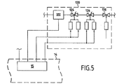
さらに他の実施形態においては、図5に示されているように、装置322を通っての圧力低下ΔP、装置322を通過する燃料の流通断面、ならびに燃料の密度を知ることによって流量の測定を可能にする装置322を使用することが可能である。流量は、ばねによってヘッドロスを設定するバルブの位置を測定するセンサ(図示されていない)によって割り出される。
In yet another embodiment, as shown in FIG. 5, the flow rate is measured by knowing the pressure drop ΔP through the
装置322が、それ自体は知られていることに気が付くべきである。欧州特許第1344917号明細書を参照することができる。また、装置322は、欧州特許第1355054号明細書など、航空機用エンジンに燃料を供給するための知られているシステムにおいて使用されている油圧計量バルブと同様の構造を有する。
It should be noted that
以上の説明においては、電気的に制御されるバルブ124、134、および136の使用を説明した。一変形例においては、油圧によって制御されるバルブも使用可能である。
In the above description, the use of electrically controlled
Claims (14)
燃料流量測定装置、制御によって絞りを変化させることができるバルブ、ならびに燃料流量測定装置およびバルブへと接続され、エンジンへと供給されるべき燃料の流量についての設定点の値の関数としてバルブを制御する制御システム、を備える燃料の流量を調節するための調節回路、
エンジンとの機械的な結合によって駆動され、航空機の燃料回路から燃料を受け取る低圧の導入口と、燃料流量調節回路へと接続された高圧の出口とを有する遠心ポンプ、および
航空機の燃料回路へと接続された導入口と、流量調節回路へと接続された出口とを有し、出口に所定の最小圧力の燃料を届けるための電気制御の補助ポンプユニット
を備え、
調節回路へと供給される燃料の圧力が、遠心ポンプおよび補助ポンプユニットによって並行して届けられる圧力のうちの大きい方である、装置。 A supply device for supplying fuel to an aircraft engine,
A fuel flow measuring device, a valve that can be throttled by control, and connected to the fuel flow measuring device and valve to control the valve as a function of the set point value for the flow of fuel to be delivered to the engine An adjustment circuit for adjusting the flow rate of the fuel, comprising a control system,
Centrifugal pump driven by mechanical coupling with the engine and receiving fuel from the aircraft fuel circuit and a high pressure outlet connected to the fuel flow regulation circuit, and into the aircraft fuel circuit An electrically controlled auxiliary pump unit for delivering fuel of a predetermined minimum pressure to the outlet, having a connected inlet and an outlet connected to the flow control circuit;
The apparatus, wherein the pressure of the fuel supplied to the regulation circuit is the greater of the pressures delivered in parallel by the centrifugal pump and the auxiliary pump unit.
圧力放出バルブが、自身の第1の導入口と自身の第2の導入口との間の圧力差が所定のしきい値を超えたときに、自身の第1の導入口を自身の出口に連通させる、請求項1に記載の装置。 An auxiliary pump unit includes a positive displacement pump, a first inlet connected to the outlet of the positive displacement pump, a second inlet connected to the fuel circuit of the aircraft, and the introduction of the positive displacement pump A pressure relief valve having an outlet connected to the mouth,
When the pressure difference between the first inlet and the second inlet exceeds a predetermined threshold, the pressure release valve turns the first inlet into its outlet. The apparatus of claim 1 in communication.
燃料供給配管の燃料の流量を測定するための装置、
供給配管に取り付けられ、制御によって絞りを変化させることができる第1のバルブ、
流量測定装置および第1のバルブへと接続され、所望の流量で燃料をエンジンに供給するように第1のバルブを制御する制御システム、
第1のバルブと直列に供給配管に取り付けられ、制御によって絞りを変化させることができる第2のバルブ、および
エンジンの過速度または過推力の検出に応答して、燃料を調節可能な減らされた流量でエンジンへと供給できるようにする第2のバルブのための制御手段
を備える、請求項1から12のいずれか一項に記載の装置。 The fuel flow control circuit
A device for measuring the flow rate of fuel in the fuel supply piping,
A first valve attached to the supply pipe and capable of changing the throttle by control;
A control system connected to the flow measuring device and the first valve for controlling the first valve to supply fuel to the engine at a desired flow rate;
A second valve attached to the supply line in series with the first valve, the throttle can be varied by control, and the fuel is reduced adjustable in response to detection of engine overspeed or overthrust 13. A device according to any one of the preceding claims, comprising control means for a second valve that allows supply to the engine at a flow rate.
Applications Claiming Priority (3)
| Application Number | Priority Date | Filing Date | Title |
|---|---|---|---|
| FR0501640A FR2882095B1 (en) | 2005-02-17 | 2005-02-17 | FUEL SUPPLY OF AN AIRCRAFT ENGINE |
| FR0501640 | 2005-02-17 | ||
| PCT/EP2006/060073 WO2006087377A1 (en) | 2005-02-17 | 2006-02-17 | Aircraft engine fuel supply |
Publications (2)
| Publication Number | Publication Date |
|---|---|
| JP2008530442A true JP2008530442A (en) | 2008-08-07 |
| JP5100398B2 JP5100398B2 (en) | 2012-12-19 |
Family
ID=35124589
Family Applications (1)
| Application Number | Title | Priority Date | Filing Date |
|---|---|---|---|
| JP2007555625A Expired - Lifetime JP5100398B2 (en) | 2005-02-17 | 2006-02-17 | Aircraft engine fuel supply |
Country Status (14)
| Country | Link |
|---|---|
| US (1) | US8205597B2 (en) |
| EP (1) | EP1853805B1 (en) |
| JP (1) | JP5100398B2 (en) |
| CN (1) | CN101128662B (en) |
| AT (1) | ATE532957T1 (en) |
| BR (1) | BRPI0607764B1 (en) |
| CA (1) | CA2597938C (en) |
| ES (1) | ES2376986T3 (en) |
| FR (1) | FR2882095B1 (en) |
| IL (1) | IL185234A (en) |
| RU (1) | RU2399778C2 (en) |
| UA (1) | UA92350C2 (en) |
| WO (1) | WO2006087377A1 (en) |
| ZA (1) | ZA200706874B (en) |
Cited By (5)
| Publication number | Priority date | Publication date | Assignee | Title |
|---|---|---|---|---|
| EP2657499A2 (en) | 2012-04-26 | 2013-10-30 | IHI Aerospace Co., Ltd. | Fluid supply device |
| WO2015046133A1 (en) | 2013-09-25 | 2015-04-02 | 株式会社Ihi | Fuel system |
| WO2015045905A1 (en) | 2013-09-25 | 2015-04-02 | 株式会社Ihi | Fuel system |
| WO2020045553A1 (en) * | 2018-08-31 | 2020-03-05 | 株式会社Ihi | Fluid supply system |
| JP2020536196A (en) * | 2017-10-05 | 2020-12-10 | ジョイント ストック カンパニー“ユナイテッド エンジン コーポレーション”(ジェイエスシー“ユーイーシー”) | How to create the required pressure and fuel flow in the fuel system of a gas turbine engine |
Families Citing this family (38)
| Publication number | Priority date | Publication date | Assignee | Title |
|---|---|---|---|---|
| FR2919673B1 (en) * | 2007-07-30 | 2014-02-28 | Hispano Suiza Sa | ASSISTANCE AND RELIEF FOR THE ELECTRIC DRIVE OF A FUEL PUMP IN A TURBOMOTEUR |
| FR2960910A1 (en) * | 2010-06-08 | 2011-12-09 | Snecma | GAS TURBINE AIRCRAFT ENGINE FUEL SUPPLY DEVICE |
| US8915088B2 (en) * | 2010-06-11 | 2014-12-23 | Hamilton Sundstrand Corporation | Fuel control method for starting a gas turbine engine |
| FR2970303B1 (en) * | 2011-01-06 | 2014-06-13 | Snecma | AERONAUTICAL TURBOMACHINE FUEL SYSTEM WITH FUEL PRESSURE CONTROL VALVE |
| FR2974149B1 (en) * | 2011-04-14 | 2015-09-25 | Snecma | FUEL SYSTEM COMPRISING MEANS FOR MONITORING A PUMP |
| US8578763B2 (en) * | 2011-06-22 | 2013-11-12 | Hamilton Sundstrand Corporation | System and method for fuel system health monitoring |
| FR2978211B1 (en) * | 2011-07-19 | 2013-08-23 | Snecma | METHOD FOR MONITORING A PRESSURE RELIEF VALVE OF A FUEL INJECTION CIRCUIT FOR TURBOMACHINE |
| GB2501289A (en) * | 2012-04-18 | 2013-10-23 | Eaton Aerospace Ltd | Aircraft fuel supply system |
| EP2844875B1 (en) | 2012-05-01 | 2020-09-02 | Eaton Corporation | Pressure compensation control of a fixed displacement pump in a pumping and metering system and associated method |
| US10451053B2 (en) | 2012-05-01 | 2019-10-22 | Eaton Intelligent Power Limited | Hydromechanical pressure compensation control of a variable displacement pump in a centrifugal pumping and metering system and associated method |
| CN102678338B (en) * | 2012-06-08 | 2014-09-17 | 中国航空工业集团公司西安飞机设计研究所 | Oil supply pressure regulating system for aircraft engine and regulating method thereof |
| CN102953835B (en) * | 2012-11-09 | 2014-11-19 | 沈阳黎明航空发动机(集团)有限责任公司 | Control device and control method for stable running of gas turbine |
| FR2999652B1 (en) * | 2012-12-18 | 2015-02-13 | Snecma | FUEL CIRCUIT OF A TURBOMACHINE |
| US9353688B2 (en) | 2013-01-17 | 2016-05-31 | Honeywell International Inc. | High pressure, multiple metering zone gas turbine engine fuel supply system |
| US9453463B2 (en) | 2013-01-17 | 2016-09-27 | Honeywell International Inc. | High efficiency, high pressure gas turbine engine fuel supply system |
| FR3003302B1 (en) * | 2013-03-12 | 2016-12-09 | Turbomeca | DEVICE FOR ASSAYING A FUEL SUPPLY CIRCUIT FOR AN ENGINE |
| US10294866B2 (en) * | 2013-11-20 | 2019-05-21 | Woodward, Inc. | Parallel metering pressure regulation system with integrated flow meter placement |
| CN103603727B (en) * | 2013-11-21 | 2015-12-09 | 中国南方航空工业(集团)有限公司 | Start fuel control system of turboshaft engine |
| WO2015166177A1 (en) * | 2014-04-28 | 2015-11-05 | Snecma | Variable geometries fluid supply circuit for a turbomachine without volumetric pump |
| FR3020403B1 (en) * | 2014-04-28 | 2019-09-13 | Safran Aircraft Engines | FLUID SUPPLY CIRCUIT FOR VARIABLE GEOMETRIES WITHOUT VOLUMETRIC PUMP AND COMBUSTION CHAMBER SUPPLY CIRCUIT WITH ELECTRIC VOLUMETRIC PUMP |
| FR3022000B1 (en) * | 2014-06-05 | 2016-10-21 | Snecma | FLUID TURBOMACHINE SUPPLY SYSTEM WITH LOW PRESSURE PUMP ASSEMBLY COMPRISING TWO PARALLEL PUMPS |
| US9885287B2 (en) | 2014-09-11 | 2018-02-06 | Honeywell International Inc. | Gas turbine engine mechanical-electrical hybrid fuel delivery system |
| WO2016154414A1 (en) * | 2015-03-25 | 2016-09-29 | Sikorsky Aircraft Corporation | Automatic adjusting fuel boost pump |
| DE102015212121A1 (en) * | 2015-06-30 | 2017-01-05 | Robert Bosch Gmbh | Method for determining operating parameters of a fuel pump |
| FR3059050B1 (en) * | 2016-11-23 | 2019-11-29 | L'air Liquide, Societe Anonyme Pour L'etude Et L'exploitation Des Procedes Georges Claude | DEVICE AND METHOD FOR CONTROLLING GAS FLOW |
| FR3061240B1 (en) * | 2016-12-22 | 2019-05-31 | Safran Aircraft Engines | IMPROVED METHOD OF REGULATING A POWER CIRCUIT |
| FR3062422B1 (en) * | 2017-01-30 | 2021-05-21 | Safran Aircraft Engines | TURBOMACHINE FUEL SUPPLY SYSTEM |
| IT201700073686A1 (en) * | 2017-06-30 | 2018-12-30 | Nuovo Pignone Tecnologie Srl | METHOD AND SYSTEM FOR THE SAFE START OF GAS TURBINES |
| CN109611247B (en) * | 2018-11-21 | 2020-12-29 | 中国航发西安动力控制科技有限公司 | Fuel oil collecting device for preventing fuel oil leakage of engine |
| FR3089247B1 (en) * | 2018-11-30 | 2020-12-18 | Airbus Helicopters | Method and system for stopping a gas turbine and vehicle |
| FR3096412B1 (en) * | 2019-05-24 | 2022-07-22 | Safran Aircraft Engines | FUEL SUPPLY SYSTEM OF A TURBOMACHINE WITH FUEL FLOW REGULATION |
| FR3098255B1 (en) * | 2019-07-03 | 2021-06-04 | Safran Aircraft Engines | Determination of fuel density for metering fuel in a fuel supply system of an aircraft engine |
| US11649768B2 (en) * | 2021-08-20 | 2023-05-16 | Hamilton Sundstrand Corporation | Pump system for a gas turbine engine |
| US11828233B2 (en) * | 2021-11-26 | 2023-11-28 | Hamilton Sundstrand Corporation | Fuel pump systems |
| US11629643B1 (en) * | 2022-01-07 | 2023-04-18 | Hamilton Sundstrand Corporation | Fuel pump systems |
| CN116146357B (en) * | 2023-02-27 | 2023-09-26 | 贵州航天林泉电机有限公司 | Feedforward control method of electric fuel pump |
| US12110827B1 (en) * | 2023-05-03 | 2024-10-08 | General Electric Company | Fuel systems for aircraft engines |
| US12366206B2 (en) * | 2023-09-11 | 2025-07-22 | Hamilton Sundstrand Corporation | Variable displacement pump (VDP) systems with dual dry out pumps |
Citations (11)
| Publication number | Priority date | Publication date | Assignee | Title |
|---|---|---|---|---|
| US2695055A (en) * | 1949-07-15 | 1954-11-23 | Gen Electric | Fuel system for thermal power plants |
| US2916875A (en) * | 1953-09-09 | 1959-12-15 | Rolls Royce | Gas turbine engine fuel systems |
| US2989842A (en) * | 1960-04-14 | 1961-06-27 | Cyrus F Wood | Fuel pumping system for engines having afterburners |
| US3946551A (en) * | 1974-01-17 | 1976-03-30 | United Technologies Corporation | Pumping and metering system |
| JPH02233831A (en) * | 1989-02-10 | 1990-09-17 | Lucas Ind Plc | Fuel feed device |
| JPH03156184A (en) * | 1989-10-31 | 1991-07-04 | Borg Warner Automot Inc | Double volume fluid pump |
| US5118258A (en) * | 1990-09-04 | 1992-06-02 | United Technologies Corporation | Dual pump fuel delivery system |
| JPH07233734A (en) * | 1994-02-23 | 1995-09-05 | Mitsubishi Heavy Ind Ltd | Fuel pressure holding device for gas turbine |
| JPH09112293A (en) * | 1995-10-20 | 1997-04-28 | Ishikawajima Harima Heavy Ind Co Ltd | Gas turbine fuel supply system |
| US5694764A (en) * | 1995-09-18 | 1997-12-09 | Sundstrand Corporation | Fuel pump assist for engine starting |
| JPH11303652A (en) * | 1998-04-23 | 1999-11-02 | Niigata Eng Co Ltd | Gas turbine engine |
Family Cites Families (22)
| Publication number | Priority date | Publication date | Assignee | Title |
|---|---|---|---|---|
| US2780172A (en) * | 1952-04-26 | 1957-02-05 | United Aircraft Corp | Dual fuel pump |
| GB758679A (en) * | 1954-01-06 | 1956-10-10 | George Raymond Shepherd | Improvements in or relating to fuel systems for aviation gas turbine power plants |
| US3774394A (en) * | 1971-08-09 | 1973-11-27 | Gen Electric | Gas turbine engine fuel drain system and cooperating valve and pump means |
| US3801228A (en) * | 1972-01-26 | 1974-04-02 | Trw Inc | Fuel pump control system and method |
| US4280323A (en) * | 1978-05-25 | 1981-07-28 | Westinghouse Electric Corp. | Gas turbine fuel control having fuel viscosity compensation to provide improved ignition reliability |
| US4245964A (en) * | 1978-11-08 | 1981-01-20 | United Technologies Corporation | Efficiency fluid pumping system including sequential unloading of a plurality of pumps by a single pressure responsive control valve |
| US4607486A (en) * | 1983-12-02 | 1986-08-26 | United Technologies Corporation | Centrifugal main fuel pump |
| US4922710A (en) * | 1989-01-04 | 1990-05-08 | General Electric Company | Integrated boost compressor/gas turbine control |
| US5116362A (en) * | 1990-12-03 | 1992-05-26 | United Technologies Corporation | Fuel metering and actuation system |
| GB9203770D0 (en) * | 1992-02-21 | 1992-04-08 | Lucas Ind Plc | Fuel control system |
| GB9325029D0 (en) * | 1993-12-07 | 1994-02-02 | Lucas Ind Plc | Pump |
| GB9518582D0 (en) * | 1995-09-09 | 1996-09-11 | Lucas Ind Plc | Fuel control system for gas turbine engine |
| RU2194181C1 (en) * | 2001-06-25 | 2002-12-10 | ОАО "Омское машиностроительное конструкторское бюро" | Gas turbine engine fuel feed and control system |
| RU2228455C2 (en) * | 2002-08-15 | 2004-05-10 | ОАО "Омское машиностроительное конструкторское бюро" | Gas-turbine engine fuel supply and control system |
| US6922625B2 (en) * | 2002-12-12 | 2005-07-26 | Honeywell International Inc. | Jet engine control and protection system and method |
| US6981359B2 (en) * | 2003-06-16 | 2006-01-03 | Woodward Governor Company | Centrifugal pump fuel system and method for gas turbine engine |
| GB0401207D0 (en) * | 2004-01-21 | 2004-02-25 | Goodrich Control Sys Ltd | Fuel supply system |
| EP1819914A2 (en) * | 2004-11-19 | 2007-08-22 | Goodrich Pump & Engine Control Systems, Inc. | Two-stage fuel pump for gas turbines |
| GB0425785D0 (en) * | 2004-11-24 | 2004-12-22 | Goodrich Control Sys Ltd | Fuel supply system |
| FR2882098B1 (en) * | 2005-02-17 | 2011-07-15 | Hispano Suiza Sa | FUEL FLOW REGULATION SUPPLYING A GAS TURBINE ENGINE |
| US7401461B2 (en) * | 2005-05-27 | 2008-07-22 | Honeywell International Inc. | Reduced-weight fuel system for gas turbine engine, gas turbine engine having a reduced-weight fuel system, and method of providing fuel to a gas turbine engine using a reduced-weight fuel system |
| FR2919673B1 (en) * | 2007-07-30 | 2014-02-28 | Hispano Suiza Sa | ASSISTANCE AND RELIEF FOR THE ELECTRIC DRIVE OF A FUEL PUMP IN A TURBOMOTEUR |
-
2005
- 2005-02-17 FR FR0501640A patent/FR2882095B1/en not_active Expired - Lifetime
-
2006
- 2006-02-17 CA CA2597938A patent/CA2597938C/en not_active Expired - Lifetime
- 2006-02-17 EP EP06708362A patent/EP1853805B1/en not_active Expired - Lifetime
- 2006-02-17 AT AT06708362T patent/ATE532957T1/en active
- 2006-02-17 UA UAA200714690A patent/UA92350C2/en unknown
- 2006-02-17 BR BRPI0607764-1A patent/BRPI0607764B1/en active IP Right Grant
- 2006-02-17 RU RU2007146447/06A patent/RU2399778C2/en active
- 2006-02-17 US US11/816,586 patent/US8205597B2/en active Active
- 2006-02-17 WO PCT/EP2006/060073 patent/WO2006087377A1/en not_active Ceased
- 2006-02-17 JP JP2007555625A patent/JP5100398B2/en not_active Expired - Lifetime
- 2006-02-17 ES ES06708362T patent/ES2376986T3/en not_active Expired - Lifetime
- 2006-02-17 CN CN2006800053163A patent/CN101128662B/en not_active Expired - Lifetime
-
2007
- 2007-08-13 IL IL185234A patent/IL185234A/en active IP Right Grant
- 2007-08-16 ZA ZA200706874A patent/ZA200706874B/en unknown
Patent Citations (11)
| Publication number | Priority date | Publication date | Assignee | Title |
|---|---|---|---|---|
| US2695055A (en) * | 1949-07-15 | 1954-11-23 | Gen Electric | Fuel system for thermal power plants |
| US2916875A (en) * | 1953-09-09 | 1959-12-15 | Rolls Royce | Gas turbine engine fuel systems |
| US2989842A (en) * | 1960-04-14 | 1961-06-27 | Cyrus F Wood | Fuel pumping system for engines having afterburners |
| US3946551A (en) * | 1974-01-17 | 1976-03-30 | United Technologies Corporation | Pumping and metering system |
| JPH02233831A (en) * | 1989-02-10 | 1990-09-17 | Lucas Ind Plc | Fuel feed device |
| JPH03156184A (en) * | 1989-10-31 | 1991-07-04 | Borg Warner Automot Inc | Double volume fluid pump |
| US5118258A (en) * | 1990-09-04 | 1992-06-02 | United Technologies Corporation | Dual pump fuel delivery system |
| JPH07233734A (en) * | 1994-02-23 | 1995-09-05 | Mitsubishi Heavy Ind Ltd | Fuel pressure holding device for gas turbine |
| US5694764A (en) * | 1995-09-18 | 1997-12-09 | Sundstrand Corporation | Fuel pump assist for engine starting |
| JPH09112293A (en) * | 1995-10-20 | 1997-04-28 | Ishikawajima Harima Heavy Ind Co Ltd | Gas turbine fuel supply system |
| JPH11303652A (en) * | 1998-04-23 | 1999-11-02 | Niigata Eng Co Ltd | Gas turbine engine |
Cited By (10)
| Publication number | Priority date | Publication date | Assignee | Title |
|---|---|---|---|---|
| EP2657499A2 (en) | 2012-04-26 | 2013-10-30 | IHI Aerospace Co., Ltd. | Fluid supply device |
| WO2015046133A1 (en) | 2013-09-25 | 2015-04-02 | 株式会社Ihi | Fuel system |
| WO2015045905A1 (en) | 2013-09-25 | 2015-04-02 | 株式会社Ihi | Fuel system |
| US9677477B2 (en) | 2013-09-25 | 2017-06-13 | Ihi Corporation | Fuel system for an engine that is capable of selectively operating a centrifugal pump to supplement a constant volume pump |
| US9964046B2 (en) | 2013-09-25 | 2018-05-08 | Ihi Corporation | Fuel System |
| JP2020536196A (en) * | 2017-10-05 | 2020-12-10 | ジョイント ストック カンパニー“ユナイテッド エンジン コーポレーション”(ジェイエスシー“ユーイーシー”) | How to create the required pressure and fuel flow in the fuel system of a gas turbine engine |
| JP7123150B2 (en) | 2017-10-05 | 2022-08-22 | ジョイント ストック カンパニー“ユナイテッド エンジン コーポレーション”(ジェイエスシー“ユーイーシー”) | How to create the required pressure and fuel flow in the fuel system of a gas turbine engine |
| WO2020045553A1 (en) * | 2018-08-31 | 2020-03-05 | 株式会社Ihi | Fluid supply system |
| JPWO2020045553A1 (en) * | 2018-08-31 | 2021-02-15 | 株式会社Ihi | Fluid supply system |
| US12044179B2 (en) | 2018-08-31 | 2024-07-23 | Ihi Corporation | Fluid supply system |
Also Published As
| Publication number | Publication date |
|---|---|
| CA2597938C (en) | 2014-09-23 |
| US20110139123A1 (en) | 2011-06-16 |
| CA2597938A1 (en) | 2006-08-24 |
| BRPI0607764B1 (en) | 2020-12-01 |
| EP1853805B1 (en) | 2011-11-09 |
| BRPI0607764A2 (en) | 2010-03-23 |
| JP5100398B2 (en) | 2012-12-19 |
| EP1853805A1 (en) | 2007-11-14 |
| ZA200706874B (en) | 2008-09-25 |
| RU2399778C2 (en) | 2010-09-20 |
| CN101128662A (en) | 2008-02-20 |
| RU2007146447A (en) | 2009-06-20 |
| UA92350C2 (en) | 2010-10-25 |
| IL185234A (en) | 2011-11-30 |
| ES2376986T3 (en) | 2012-03-21 |
| FR2882095B1 (en) | 2011-05-06 |
| FR2882095A1 (en) | 2006-08-18 |
| IL185234A0 (en) | 2008-02-09 |
| WO2006087377A1 (en) | 2006-08-24 |
| CN101128662B (en) | 2010-06-16 |
| ATE532957T1 (en) | 2011-11-15 |
| US8205597B2 (en) | 2012-06-26 |
Similar Documents
| Publication | Publication Date | Title |
|---|---|---|
| JP5100398B2 (en) | Aircraft engine fuel supply | |
| JP4896893B2 (en) | Apparatus for supplying fuel to a gas turbine engine while adjusting the fuel flow rate | |
| US8166765B2 (en) | Fuel delivery and control system including a variable displacement actuation pump supplementing a fixed displacement main pump | |
| CN100507240C (en) | Improved fuel delivery system | |
| EP1965055B1 (en) | Metering demand fuel system | |
| US8286432B2 (en) | Electric power generating turbine engine fuel supply system | |
| US7895819B2 (en) | Assistance and emergency backup for the electrical drive of a fuel pump in a turbine engine | |
| US7762080B2 (en) | Fuel metering pump calibration method | |
| US6675570B2 (en) | Low-cost general aviation fuel control system | |
| WO2002031332A1 (en) | Methods and apparatus for rotor overspeed and overboost protection | |
| US20050144957A1 (en) | Methods for operating gas turbine engines | |
| CN113710887B (en) | Turbine fuel supply system for regulating fuel flow | |
| RU2619518C1 (en) | Gas turbine engine fuel feed system | |
| US12345211B2 (en) | Uncommanded or uncontrollable high thrust detection and mitigation |
Legal Events
| Date | Code | Title | Description |
|---|---|---|---|
| A621 | Written request for application examination |
Free format text: JAPANESE INTERMEDIATE CODE: A621 Effective date: 20081021 |
|
| A131 | Notification of reasons for refusal |
Free format text: JAPANESE INTERMEDIATE CODE: A131 Effective date: 20110118 |
|
| A601 | Written request for extension of time |
Free format text: JAPANESE INTERMEDIATE CODE: A601 Effective date: 20110413 |
|
| A602 | Written permission of extension of time |
Free format text: JAPANESE INTERMEDIATE CODE: A602 Effective date: 20110420 |
|
| A521 | Request for written amendment filed |
Free format text: JAPANESE INTERMEDIATE CODE: A523 Effective date: 20110715 |
|
| A711 | Notification of change in applicant |
Free format text: JAPANESE INTERMEDIATE CODE: A711 Effective date: 20111007 |
|
| A521 | Request for written amendment filed |
Free format text: JAPANESE INTERMEDIATE CODE: A821 Effective date: 20111007 |
|
| A131 | Notification of reasons for refusal |
Free format text: JAPANESE INTERMEDIATE CODE: A131 Effective date: 20120110 |
|
| A521 | Request for written amendment filed |
Free format text: JAPANESE INTERMEDIATE CODE: A523 Effective date: 20120330 |
|
| TRDD | Decision of grant or rejection written | ||
| A01 | Written decision to grant a patent or to grant a registration (utility model) |
Free format text: JAPANESE INTERMEDIATE CODE: A01 Effective date: 20120911 |
|
| A01 | Written decision to grant a patent or to grant a registration (utility model) |
Free format text: JAPANESE INTERMEDIATE CODE: A01 |
|
| A61 | First payment of annual fees (during grant procedure) |
Free format text: JAPANESE INTERMEDIATE CODE: A61 Effective date: 20120925 |
|
| FPAY | Renewal fee payment (event date is renewal date of database) |
Free format text: PAYMENT UNTIL: 20151005 Year of fee payment: 3 |
|
| R150 | Certificate of patent or registration of utility model |
Ref document number: 5100398 Country of ref document: JP Free format text: JAPANESE INTERMEDIATE CODE: R150 Free format text: JAPANESE INTERMEDIATE CODE: R150 |
|
| R250 | Receipt of annual fees |
Free format text: JAPANESE INTERMEDIATE CODE: R250 |
|
| R250 | Receipt of annual fees |
Free format text: JAPANESE INTERMEDIATE CODE: R250 |
|
| R250 | Receipt of annual fees |
Free format text: JAPANESE INTERMEDIATE CODE: R250 |
|
| R250 | Receipt of annual fees |
Free format text: JAPANESE INTERMEDIATE CODE: R250 |
|
| R250 | Receipt of annual fees |
Free format text: JAPANESE INTERMEDIATE CODE: R250 |
|
| R250 | Receipt of annual fees |
Free format text: JAPANESE INTERMEDIATE CODE: R250 |
|
| R250 | Receipt of annual fees |
Free format text: JAPANESE INTERMEDIATE CODE: R250 |
|
| R250 | Receipt of annual fees |
Free format text: JAPANESE INTERMEDIATE CODE: R250 |
|
| R250 | Receipt of annual fees |
Free format text: JAPANESE INTERMEDIATE CODE: R250 |
|
| R250 | Receipt of annual fees |
Free format text: JAPANESE INTERMEDIATE CODE: R250 |
|
| R250 | Receipt of annual fees |
Free format text: JAPANESE INTERMEDIATE CODE: R250 |