JP2008308319A - Sheet feeding apparatus and image forming apparatus - Google Patents
Sheet feeding apparatus and image forming apparatus Download PDFInfo
- Publication number
- JP2008308319A JP2008308319A JP2007159963A JP2007159963A JP2008308319A JP 2008308319 A JP2008308319 A JP 2008308319A JP 2007159963 A JP2007159963 A JP 2007159963A JP 2007159963 A JP2007159963 A JP 2007159963A JP 2008308319 A JP2008308319 A JP 2008308319A
- Authority
- JP
- Japan
- Prior art keywords
- sheet
- feeding
- roller
- sheet feeding
- image forming
- Prior art date
- Legal status (The legal status is an assumption and is not a legal conclusion. Google has not performed a legal analysis and makes no representation as to the accuracy of the status listed.)
- Pending
Links
Images



Landscapes
- Sheets, Magazines, And Separation Thereof (AREA)
- Controlling Sheets Or Webs (AREA)
Abstract
【課題】本発明は、小型化できてかつ安定した給送性能を維持しつつ、シートへの曲げ癖がつくことを抑制し、ジャムや画像形成上の問題を抑制し、ユーザビリティを向上できるシート給送装置及び画像形成装置を提供することを目的とする。
【解決手段】本発明に係るシート給送装置の代表的な構成は、シートを積載するシート積載板111と、シート積載板111からシートを送り出す給送ローラ113と、シート積載板111を昇降させて、シートと給送ローラ113を当接及び離間するリフトレバー112、加圧バネ126と、リフトレバー112、加圧バネ126を制御するシート搬送制御部207と、を有するシート給送装置において、シート搬送制御部207は、リフトレバー112、加圧バネ126の降下を開始するタイミング、リフトレバー112、加圧バネ126を降下させる際の下降量の少なくとも一方を変更することを特徴とする。
【選択図】図1The present invention relates to a sheet that can be reduced in size and can maintain stable feeding performance, suppresses bending wrinkles on the sheet, suppresses jamming and image formation problems, and improves usability. It is an object to provide a feeding device and an image forming apparatus.
A representative configuration of a sheet feeding apparatus according to the present invention includes a sheet stacking plate 111 for stacking sheets, a feed roller 113 for feeding a sheet from the sheet stacking plate 111, and a sheet stacking plate 111 that moves up and down. In the sheet feeding apparatus having the lift lever 112 that contacts and separates the sheet from the feeding roller 113, the pressure spring 126, and the sheet conveyance control unit 207 that controls the lift lever 112 and the pressure spring 126. The sheet conveyance control unit 207 is characterized in that it changes at least one of the timing at which the lift lever 112 and the pressure spring 126 start to descend, and the amount by which the lift lever 112 and the pressure spring 126 are lowered.
[Selection] Figure 1
Description
本発明は複写機やプリンタ、ファクシミリ等の画像形成装置及びこれに搭載されるシート給送装置に関するものである。 The present invention relates to an image forming apparatus such as a copying machine, a printer, and a facsimile, and a sheet feeding apparatus mounted on the image forming apparatus.
シート給送装置におけるシート分離手段として、従来から、様々な方法が提案されている。 Conventionally, various methods have been proposed as sheet separating means in the sheet feeding apparatus.
シート分離手段の一例として、分離パットを採用したものがある。この方式は、給送ローラと分離パットとの間に複数枚のシートが送り込まれた場合、給送ローラと分離パットとの摩擦分離作用により最上位以外のシートをせき止める。この方式によれば、シート分離部を小さくできる。 As an example of the sheet separating means, there is one employing a separation pad. In this method, when a plurality of sheets are fed between the feeding roller and the separation pad, the sheets other than the uppermost sheet are blocked by the frictional separation action between the feeding roller and the separation pad. According to this method, the sheet separating unit can be made small.
シート分離手段の他の例として、トルクリミッタ機能を有した分離ローラを採用したものがある(特許文献1参照)。この方式は、駆動する給送ローラに回転可能な分離ローラを圧接し、トルクリミッタを分離ローラの同軸上、もしくは分離ローラに内蔵し、そのトルクリミッタの制動トルクによってシートを分離する。 As another example of the sheet separating means, there is one that employs a separation roller having a torque limiter function (see Patent Document 1). In this method, a rotatable separation roller is pressed against a driving feeding roller, and a torque limiter is provided on the same axis as the separation roller or in the separation roller, and the sheet is separated by the braking torque of the torque limiter.
即ち、給送ローラと分離ローラの間にシートが1枚のみある場合、トルクリミッタにはシートを介して給送ローラから大きな回転トルクが作用し、トルクリミッタが給送ローラと分離ローラの連れ回りを許容する。一方、給送ローラと分離ローラの間に複数枚のシートがある場合には、トルクリミッタにはシート間の摩擦による比較的小さな回転トルクが作用し、トルクリミッタが給送ローラと分離ローラとの連れ回りを阻止する。そして、給送ローラで1枚のシートを搬送し、分離ローラで他のシートが搬送されるのを阻止する。この方式によれば、分離パッドを用いたシート分離方式に比べて、耐久性に優れ、パッドとシートのビビリによる異音もなく、安定したシートの給送を行うことができる。 That is, when there is only one sheet between the feeding roller and the separation roller, a large rotational torque acts on the torque limiter from the feeding roller via the sheet, and the torque limiter rotates with the feeding roller and the separation roller. Is acceptable. On the other hand, when there are a plurality of sheets between the feeding roller and the separation roller, a relatively small rotational torque due to the friction between the sheets acts on the torque limiter, and the torque limiter is connected between the feeding roller and the separation roller. Stops accompanying you. Then, one sheet is conveyed by the feeding roller and another sheet is prevented from being conveyed by the separation roller. According to this method, compared to a sheet separation method using a separation pad, the sheet is excellent in durability, and stable sheet feeding can be performed without noise due to chatter between the pad and the sheet.
シート分離手段の他の例として、シートを送り出すピックアップローラと給送ローラを共用し、1つの給送ローラによりピックアップと給送を行い、分離ローラによって分離して画像形成部へシートを搬送するものがある(特許文献2参照)。この方式によれば、部品点数が削減できることからコストダウンが図れ、またシート分離部のスペースを縮小することができ、つまりは装置小型化を図ることができる。 As another example of the sheet separating means, a pickup roller for feeding out a sheet and a feeding roller are shared, the pickup and feeding are performed by one feeding roller, and the sheet is separated by the separating roller and conveyed to the image forming unit. (See Patent Document 2). According to this method, since the number of parts can be reduced, the cost can be reduced, and the space of the sheet separating portion can be reduced, that is, the apparatus can be downsized.
その他にも、従来のシート給送装置において、積載されているシートの上面とピックローラの圧接力(以下、給送圧という)を設定するための機構がいろいろ提案されている。 In addition, in the conventional sheet feeding apparatus, various mechanisms for setting the pressure contact force (hereinafter referred to as feeding pressure) between the upper surface of the stacked sheets and the pick roller have been proposed.
例えば、爪分離方式でアームと引っ張りバネを用いた第一の加圧手段と、第一の加圧手段だけでは不足する給送圧を補うために、圧縮コイルバネを用いた第二の加圧手段を追加した構成が提案されている(特許文献3参照)。これはシート積載板を加圧する加圧手段を加圧機能の異なる2種類の加圧手段によって構成し、シート補給の容易化と安定した給送性能の向上を図っている。 For example, a first pressurizing unit that uses an arm and a tension spring in a claw separation method, and a second pressurizing unit that uses a compression coil spring to compensate for a feeding pressure that is insufficient only by the first pressurizing unit The structure which added is proposed (refer patent document 3). In this configuration, the pressurizing means for pressurizing the sheet stacking plate is constituted by two kinds of pressurizing means having different pressurizing functions, thereby facilitating the sheet supply and improving the stable feeding performance.
しかしながら、上記従来技術では、複数枚のシートが積載されるシート積載部からシートを1枚ずつ分離して送り出す構成にあるため、シートを送り出した後に残る次のシートが分離部に残留する。残留したシートは、先端が、給送ローラ、シート積載部、分離パッド或いは分離ローラ等に挟まれた状態であり、この状態のまま長時間放置されてしまうと、分離部の形状に屈曲したままシート先端部に曲げ癖が付いてしまう。 However, in the above prior art, since the sheets are separated and sent out one by one from the sheet stacking unit on which a plurality of sheets are stacked, the next sheet remaining after the sheet is sent out remains in the separating unit. The remaining sheet is in a state where the leading edge is sandwiched between a feeding roller, a sheet stacking unit, a separation pad, or a separation roller, and if left in this state for a long time, it remains bent in the shape of the separation unit. Bending wrinkles are attached to the leading edge of the sheet.
特に、シートを送り出すピックアップローラと給送ローラを共用し、1つの給送ローラによりピックアップと給送を行い、分離ローラによって分離して画像形成部へシートを搬送するシート給送装置の場合は、この現象が、より顕著となる。 In particular, in the case of a sheet feeding apparatus that shares a pickup roller and a feeding roller for feeding out a sheet, performs pickup and feeding by a single feeding roller, and separates the sheet by a separation roller and conveys the sheet to an image forming unit. This phenomenon becomes more prominent.
この構成では、シートのピックアップと給送を兼ねて動作させるために給送ローラの径に比べてシートを分離するための分離ローラは、シート積載部の近傍に位置し、比較的小径である必要がある。 In this configuration, the separation roller for separating the sheet as compared with the diameter of the feeding roller is required to be located in the vicinity of the sheet stacking portion and to have a relatively small diameter compared with the diameter of the feeding roller in order to operate both for sheet pickup and feeding. There is.
シートが給送される際には、給送ローラと小径の分離ローラの当接部で、給送されたシートとその次のシートが分離されるため、シート給送動作終了後は必ず、次のシートの先端部が給送ローラと分離ローラ、およびシート積載部に挟まれた状態となってしまう。すると、分離ローラが小径でシート積載部の近傍にあるために、より大きな屈曲となり、比較的短時間でも、シートに大きな曲げ癖が付いてしまう、という問題があった。 When a sheet is fed, the fed sheet and the next sheet are separated at the contact portion between the feeding roller and the small-diameter separation roller. The leading edge of the sheet is sandwiched between the feeding roller, the separation roller, and the sheet stacking unit. Then, since the separation roller has a small diameter and is in the vicinity of the sheet stacking portion, there is a problem that the sheet is bent more greatly, and the sheet is greatly bent even in a relatively short time.
先端が屈曲しているシートを給送すると、画像形成装置内部の搬送路で、先端が引っ掛かり易くなり、種々の紙詰まり(ジャム)を引き起こす。また、画像形成の際は、屈曲部の像形成時に不具合が発生し、屈曲部に適正な像が形成されないなど、画像上の問題を引き起こしたりしていた。 When a sheet having a bent leading edge is fed, the leading edge is easily caught in the conveyance path inside the image forming apparatus, and various paper jams (jams) are caused. Further, when an image is formed, a problem occurs when forming an image of the bent portion, causing an image problem such that an appropriate image is not formed on the bent portion.
そこで本発明は、小型化できてかつ安定した給送性能を維持しつつ、シートへの曲げ癖がつくことを抑制し、ジャムや画像形成上の問題を抑制し、ユーザビリティを向上できるシート給送装置及び画像形成装置を提供することを目的とする。 Therefore, the present invention provides a sheet feeding that can be downsized and maintain stable feeding performance, suppresses bending wrinkles on the sheet, suppresses jams and image formation problems, and improves usability. An object is to provide an image forming apparatus and an image forming apparatus.
上記課題を解決するために本発明に係るシート給送装置の代表的な構成は、シートを積載するシート積載手段と、前記シート積載手段からシートを送り出すシート給送手段と、前記シート積載手段を昇降させて、シートと前記シート給送手段を当接及び離間させる昇降手段とを有するシート給送装置において、前記昇降手段の降下を開始するタイミングと、前記昇降手段を降下させる際の下降量との少なくとも一方が変更可能であることを特徴とする。 In order to solve the above problems, a typical configuration of a sheet feeding apparatus according to the present invention includes a sheet stacking unit that stacks sheets, a sheet feeding unit that feeds sheets from the sheet stacking unit, and the sheet stacking unit. In a sheet feeding apparatus having lifting and lowering means that lifts and lowers the sheet and contacts and separates the sheet feeding means, a timing for starting the lowering of the lifting and lowering and a lowering amount when lowering the lifting and lowering means At least one of the above can be changed.
上記課題を解決するために本発明に係る画像形成装置の代表的な構成は、前記シート給送装置と、前記シート給送装置により給送されたシートにトナー像を形成する画像形成手段と、を有することを特徴とする。 In order to solve the above problems, a typical configuration of an image forming apparatus according to the present invention includes the sheet feeding device, an image forming unit that forms a toner image on a sheet fed by the sheet feeding device, and It is characterized by having.
本発明によれば、小型化できてかつ安定した給送性能を維持しつつ、シートへの曲げ癖がつくことを抑制し、ジャムや画像形成上の問題を抑制し、ユーザビリティを向上できる。 According to the present invention, it is possible to reduce the size of the sheet while maintaining stable feeding performance, and to suppress bending wrinkles on the sheet, to suppress jamming and image formation problems, and to improve usability.
[第一実施形態]
本発明に係るシート給送装置及び画像形成装置の第一実施形態について、図を用いて説明する。図1は本実施形態の画像形成装置の構成図である。
[First embodiment]
A first embodiment of a sheet feeding apparatus and an image forming apparatus according to the present invention will be described with reference to the drawings. FIG. 1 is a configuration diagram of an image forming apparatus according to the present embodiment.
(画像形成装置100)
図1に示すように、画像形成装置100は、トナーカートリッジ101、半導体レーザ103、回転多面鏡105、転写ローラ109、定着器110、トップセンサ117、定着センサ118、シート給送装置50を有している。
(Image forming apparatus 100)
As shown in FIG. 1, the
トナーカートリッジ(画像形成手段)101は、静電担持体である感光体ドラム102、帯電ローラ107、現像器108を有している。トナーカートリッジ101は、プリンタ本体に着脱可能である。
A toner cartridge (image forming unit) 101 includes a
トップセンサ117は、感光体ドラム102への画像書き込み(記録/印字)とシート搬送の同期を取ってシートSを転写部へ搬送する。また、トップセンサ117は、給送されたシートSの搬送方向の長さを測定することができる。
The
定着センサ118は、定着器110のシート搬送方向下流側に設けられ、定着後のシートSの有無を検出する。なお、画像形成動作の詳細は後述する。
The
(シート給送装置50)
シート給送装置50は、シート積載板111、リフトレバー112、シートカセット本体122、シートカセット本体検出スイッチ123を有する。シート給送装置50は、リフトレバー上昇検出センサ124、シート有無検知センサ125、加圧バネ126、温度センサ501、シート積載量センサ502を有する。シートカセット本体122は、画像形成装置100から着脱可能である。
(Sheet feeding device 50)
The
シートSを積載するシート積載手段であるシート積載板111は、シート搬送方向下流側を揺動中心として揺動可能に支持されている。。シート積載板111は、その裏面側(図中下側)から付勢手段としての加圧バネ126によりシート搬送方向上流側を上方に押圧される。加圧バネ126は、シート積載板111とリフターモータ(不図示)からの駆動を受けて昇降するリフトレバー112との間で支持されている。昇降手段であるリフトレバー112は及び加圧バネ126を介してシート積載板111を昇降させて、シートSと給送ローラ113を当接及び離間させる。
A
リフトレバー112の上昇により、シート積載板111に積載された最上位のシートSの搬送方向先端側はピックアップと給送を共用するシート給送手段である給送ローラ113へ押圧される。給送ローラ113は、シート積載板111上に積載された最上位のシートSの接した状態で、シート搬送方向下流側ではシート分離ローラ(シート分離手段)114と接している。シート分離ローラ114は、給送ローラ113とシート積載板111上の最上位シートSとの接触部(ニップ部)から下流側に配置される。
As the
スイッチ123は、シートカセット本体122の装置本体への装着状態を検知する。センサ124は、不図示のリフターモータがリフトレバー112を上昇させた時、シートSが給送可能な位置まで上昇したかどうかを検知するためのシート高さ検知用のセンサである。センサ125は、シート積載板111上にシートが積載されているかを検出するシート有無検知用のセンサである。
The
温度センサ501は、シートカセット本体122内のシートS近傍に設けられ、シートSの雰囲気温度(シート周辺の温度)を計測する環境検知手段である。シート積載量センサ502は、シートSの積載量を検出する。
The
画像形成装置100のスタンバイ状態では、電源投入時や、シートカセット本体122を画像形成装置100へ挿入した時と同様、図3(a)に示すように、リフトレバー112およびシート積載板111は、下降した状態にある。この時、シート積載板111に積載されている最上位のシートSは、給送ローラ113には接していない状態であり、給送できない状態にある。
In the standby state of the
一方、プリント動作開始時は、図3(b)のように、リフターモータ(不図示)が駆動し、センサ124がリフトレバー112の上昇を検知するまでリフトレバー112を上昇させる。リフトレバー112がセンサ124により検知可能な位置まで上昇した時、初めてシートSの給送動作が可能となる。すなわち、シート積載板111は、リフトレバー112により加圧バネ126を介して押し上げられ、積載された最上位のシートSの搬送方向下流側が給送ローラ113に接した状態になる。この時、加圧バネ126は、積載されたシートSの量が少量の場合であっても、最上位のシートSが常に給送ローラ113に押圧される様にシート積載板111を上方に押圧している。そして、プリント動作中は図3(b)の給送可能状態に保持される。
On the other hand, at the start of the printing operation, as shown in FIG. 3B, a lifter motor (not shown) is driven, and the
給送可能状態において、給送ローラ113は駆動モータ(不図示)により駆動を受け、図1において反時計回りに回転する。これにより、シート積載板111上に積載された最上位のシートSをシート分離ローラ114によって後続シートと分離し、シート搬送方向下流方向へ搬送する。
In a feedable state, the
(画像形成装置100の制御系の回路構成)
図2は画像形成装置100の制御系の回路構成のブロック図である。図2に示すように、画像形成装置100の制御系の回路は、ビデオコントローラ201、エンジンコントローラ202、高圧制御部203、光学系制御部204を有している。画像形成装置100の制御系の回路は、定着器制御部205、センサ入力部206、シート搬送制御部207、コントロールパネル601を有している。
(Circuit configuration of control system of image forming apparatus 100)
FIG. 2 is a block diagram of a circuit configuration of a control system of the
ビデオコントローラ201は、ホストコンピュータ等の外部機器(不図示)から送られる画像コードデータを画像形成装置100の印字に必要なビットデータに展開するとともに、画像形成装置100の内部情報を読み取り、それを表示する。
The
エンジンコントローラ202は、画像形成装置100の各部をビデオコントローラ201の指示に従ってプリント動作の制御をするとともに、ビデオコントローラ201へプリンタ内部情報を報知する。
The
高圧制御部203は、エンジンコントローラ202の指示に従って、帯電、現像、転写等各工程における各高圧出力制御を行う。
The high
光学系制御部204は、スキャナモータ104の駆動/停止、レーザビームの点灯をエンジンコントローラ202の指示に従って制御する。スキャナモータ104の回転により回転多面鏡105が回転する。
The optical
定着器制御部205は、エンジンコントローラ202の指示に従って、定着器110内のヒータへの通電の駆動/停止を行う。
The fixing
センサ入力部206は、センサ117、118、124、125、スイッチ123等からの検出結果をエンジンコントローラ202へ報知する。
The
シート搬送制御部207は、エンジンコントローラ202の指示に従い、シートS搬送のために、不図示の駆動モータやリフターモータ、ローラ等の駆動/停止を行い、リフトレバー112、加圧バネ126を制御する制御手段である。シート搬送制御部207は、給送ローラ113、搬送ローラ対115、レジストローラ対116、感光体ドラム102、定着器110、排出搬送ローラ対119、排出ローラ対120等の搬送系の駆動/停止を行う。シート搬送制御部207は、温度センサ501の検知結果に応じて、リフトレバー112を降下させるまでの時間を変更する。
In accordance with an instruction from the
コントロールパネル601は、シートカセット本体122に積載するシートSの材質に応じた設定を行う入力手段であり、入力したシートSの材質をビデオコントローラ202がメモリに記憶する。
The control panel 601 is an input unit that performs setting according to the material of the sheet S stacked on the
(プリント動作)
次にプリント動作について説明する。
(Print operation)
Next, the printing operation will be described.
エンジンコントローラ202は、ビデオコントローラ201からプリント動作開始命令を受けると、プリント動作を開始する。エンジンコントローラ202は、制御部203〜205へ命令を送り、駆動モータ(不図示)の駆動、定着器110の立上げ、スキャナモータ104の駆動を開始する。駆動モータ(不図示)の駆動によって、感光体ドラム102、転写ローラ109、搬送ローラ対115、排出搬送ローラ対119、排出ローラ対120がそれぞれ回転を開始する。
When the
この時、シート搬送制御部207は、リフターモータ(不図示)を制御して、リフトレバー112の上昇を開始する。エンジンコントローラ202は、センサ124がリフトレバー112が所定の位置まで上昇するのを検知するまでリフターモータ(不図示)を駆動する。リフターモータ(不図示)の駆動開始から、センサ124がリフトレバー112の所定位置への上昇を検知するまでの上昇時間Tを計測しておき、エンジンコントローラ202内のメモリ(不図示)に記憶しておく。これらの動作により、最上位のシートSの先端側は、給送ローラ113に押圧され、シートSを給送可能な状態にして待機する。
At this time, the sheet
この後、エンジンコントローラ202は、レーザビームの光量制御を開始するとともに、帯電ローラ107、現像器108、転写ローラ109の高圧駆動を順次行う。エンジンコントローラ202は、レーザビームセンサ(不図示)より送られるビーム検知信号のパルス間隔から回転多面鏡105の回転が定常状態になったことを検知する。この検知により、給送ローラ113を回転させて、シートカセット本体122内のシートSを最上位側から一枚送り出す。この時、最上位のシートSにつられ、後続のシートSも一緒に移動を始める場合がある。この場合には、後続のシートSは、先端がシート分離ローラ114にぶつかり、移動が阻止され、先行のシートSのみが移動していく。そして先行のシートSは、搬送ローラ対115により搬送される。給送ローラ113は、シートカセット本体122からシートSを一枚送り出し終わると、直ちに停止される。
Thereafter, the
送り出されたシートSは、搬送ローラ対115によってレジストローラ対116に向けて搬送される。シートSは、搬送ローラ対115、レジストローラ対116によって、画像転写領域(感光体ドラム102と転写ローラ109とのニップ部)へ向けて搬送される。エンジンコントローラ202は、シートSがトップセンサ117に到達したことを検知して同期信号をビデオコントローラ201に対して出力開始する。
The fed sheet S is conveyed toward the
この時、ビデオコントローラ201は、画像情報のドットイメージへの展開を開始しており、画像信号出力開始の準備を完了している。ビデオコントローラ201は、エンジンコントローラ202からの同期信号を受信して1ページ分の画像データとして画像信号の出力を開始する。
At this time, the
シートSはトップセンサ117を通過した後、画像転写領域(ニップ部)に達する。
After passing through the
この時、エンジンコントローラ202は、ビデオコントローラ201からの画像信号に応じて半導体レーザ(光源)103を駆動する。半導体レーザ103から発射したレーザビーム106は、回転多面鏡105の回転によって直線状の走査に変換され、結像レンズ、折り返しミラー等を介して感光体ドラム102に照射される。
At this time, the
感光体ドラム102は、図1中時計回り方向に所定の周速度(プロセススピード)にて回転駆動される。感光体ドラム102はその回転過程で帯電手段としての帯電ローラ107により所定の極性・電位に一様に帯電処理される。その感光体ドラム102の一様帯電面に対して、目的の画像情報の時系列電気デジタル画素信号に対して変調制御(ON/OFF制御)されたレーザビーム106による走査露光がなされ、感光体ドラム102の表面に目的の画像情報の静電潜像が形成される。感光体ドラム102上に形成された静電潜像は、現像手段としての現像器108で現像材(トナー)によりトナー像として現像されて可視化される。
The
一方、シートSは、画像転写領域(ニップ部)を搬送されつつ、そのシートSの表面に感光体ドラム102面側のトナー画像が順次転写されていく。ニップ部を通過したシートSは、回転過程の感光体ドラム102の面から順次分離されて、トナー画像を定着させるための定着器110に導入される。定着器110内では、熱と圧力を加えて、シートS上のトナー画像を熱定着処理する。定着器110を出たシートSは、排出搬送ローラ対119、排出ローラ対120により排出トレイ121排出される。
On the other hand, the toner image on the surface of the
また、シートSを分離した後の感光体ドラム102は、クリーニング手段(不図示)により転写残りトナー等の付着汚染物の除去処理を受けて清浄され、繰り返して帯電処理から始まる電子写真画像形成に供される。エンジンコントローラ202は、高圧制御、光学制御、定着制御を終えて次のプリント動作への準備を整えつつ、動作を終了するとともに駆動モータを停止させる。
In addition, the
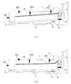
図4(a)に示すように、給送動作を終えると、シートカセット本体122内に残された後続のシートSは、先端部分が給送ローラ113とシート分離ローラ114に挟まれ、更に給送ローラ113と積載されたシートSの束に挟まれた状態となっている。結果として、シート分離ローラ114と積載されたシートSの束の間で、シートSは下側に折り曲げられ、このままの状態で長時間放置されると、シートSの先端部分が挟まれた形状に曲げ癖が付いてしまう。
As shown in FIG. 4A, when the feeding operation is finished, the subsequent sheet S remaining in the sheet cassette
そこで、エンジンコントローラ202は、所定の時間T1だけリフターモータを逆回転させ、リフトレバー112を下降させる。この時、所定の時間T1は、T1≦Tとなる時間になる様にするのが好ましい。なぜなら、通常の場合、リフトレバー112は上昇時よりも下降時の方が、リフターモータの動作トルクが軽くなり、より短時間で下降する傾向にあるためである。
Therefore, the
このような時間設定にすることにより、リフトレバー112を下降させる際に、下降を検知させるためのセンサが不要となり、コストをおさえることができる。また、リフターモータの回転スピードの個体バラツキや昇降部の負荷バラツキ、環境変化や経時変化等によるにバラツキを吸収し、リフターモータを逆回転させ過ぎて昇降部を破壊してしまうことを抑制できる。
By setting the time as described above, when the
そして、図4(b)に示すように、リフトレバー112を下降させることにより、給送ローラ113と積載されたシートSの束が離間し、シートS先端への曲げストレスを軽減できる。
Then, as shown in FIG. 4B, by lowering the
(シート積載板111の下降開始タイミング及び下降量)
シート給送装置50は、リフターモータ(不図示)がシート積載板111を下降させるまでの時間及び、シート積載板111の下降量を変更可能である。シート積載板111の下降量は、所定の時間T1(T1≦T)によって決まる。
(Descent start timing and descending amount of the sheet stacking plate 111)
The
シート分離ローラ114と積載されたシートSの束の間で、挟まれて付くシートSの曲げ癖は、シートSの材質により、付き方が違う。つまり、短時間で顕著な曲げ癖が付いてしまうシートや、比較的長時間放置しても、それほど酷い曲げ癖が着かないシートがある。
Depending on the material of the sheet S, the way in which the bending wrinkles of the sheet S sandwiched between the
更に、シートの積載量によっても、曲げ癖の付き方が変わってくる。これは、シート積載板111を上昇させる際は、シートの積載量に依らず、リフトレバー112を常にセンサ124の位置まで上昇させるためである。つまり、リフトレバー112がセンサ124の位置にある時、シートSの積載量によってシート積載板111の押し上げ量を変化させて、最上位のシートSの給送ローラ113へ当接させる必要がある。その変化量は、加圧バネ126の伸縮によって吸収している。従って、シートSの積載量(残量)によって、シートSと給送ローラ113の押圧も変わってくる。具体的には、シートSの積載量が多いほど、シート積載板111を押し上げる距離が短くなり、加圧バネ126の伸びが短くなり、押圧力が大きくなる。
Furthermore, the way the bends are attached varies depending on the amount of sheets loaded. This is because when the
このように、シートSの積載量によって曲げ癖の付き方が違い、シートSの積載量が多いほど、癖の付き方も顕著になる。また、シートSの積載量が少ないほど、加圧バネ126が伸びているため、リフトレバー112の下降量が少なくても給送ローラ113と積載されたシートSの束を離間できる。よって、シートSの積載量が少ないほど、リフトレバー112の下降量が少なくて済む。
As described above, the bending crease differs depending on the stacking amount of the sheets S. The greater the stacking amount of the sheets S, the more prominent the crease. Further, since the
また、画像形成装置100が設置されている環境、例えば、温度や湿度によっても曲げ癖の付き方が変化し、温度が高いほど、曲げ癖が付き易い。
In addition, the manner in which the bending wrinkles change depending on the environment in which the
一方、給送ローラ113と積載されたシートSの束を離間させると、プリント時間が長くなってしまう。例えば、シート積載板111は給送動作を行う時以外は常に一番下まで下げて給送ローラ113と積載されたシートSの束を離間すると、プリント動作を開始する際は必ずシート積載板111を給送動作可能な位置まで上昇しなければならない。すると、シート積載板111の上昇動作に時間がかかり、最初のプリント動作に時間がかかってしまい、プリント時間が長くなってしまう。
On the other hand, if the feeding
そこで、シートSに曲げ癖が付かない範囲で、極力シート積載板111の下降量を少なくし、給送ローラ113と積載されたシートSの束を当接させている時間をより長くすることが、プリンタの性能上は有効である。
Therefore, as long as the sheet S is not bent, the lowering amount of the
(シート積載板111の下降開始タイミング及び下降量の決定)
ユーザーは、シートカセット本体122を引き出し、シートSを積載する。この時、リフトレバー112は、リフターモータ(不図示)からの駆動が外れ、一番下まで降りている。
(Determination of start timing and amount of lowering of the sheet stacking plate 111)
The user pulls out the
シートカセット本体122が装着されたことをスイッチ123が検知すると、その情報をエンジンコントローラ202がビデオコントローラ201に報知する。ビデオコントローラ201は、コントロールパネル601に表示を行い、ユーザーへ、シートカセット本体122へセットしたシートSの材質を設定するように促す。ユーザーがコントロールパネル601を介して材質情報を入力すると、ビデオコントローラ201が材質情報をメモリに記憶保持する。
When the
そして、エンジンコントローラ202は、リフターモータ(不図示)を制御して、リフトレバー112の上昇を開始する。エンジンコントローラ202は、センサ124がリフトレバー112の上昇を検知するまでリフターモータを駆動する。この時、リフターモータの駆動開始から、センサ124がリフトレバー112の上昇を検知するまでの上昇時間Tをエンジンコントローラ(時間計測手段)202で計測する。そして、エンジンコントローラ202内のメモリ(不図示)に計測結果(上昇時間)Tを記憶しておく。
Then, the
最上位のシートSの先端側はこれらの動作により、給送ローラ113に押圧され、シートSを給送可能な状態にして待機する。この場合は、シートSは先端部分が給送ローラ113と積載されたシートSの束に挟まれただけの状態であり、シートSの先端部分が挟まれた形状に曲げ癖が付いてしまう、といった心配はない。
The leading edge side of the uppermost sheet S is pressed by the feeding
この状態から上述のプリント動作を開始し、プリント動作を終えた時、エンジンコントローラ202は、最後の給送動作終了後(最後のシートSの給送後)からの経過時間tの計測を開始している。そして、シート積載量センサ502によってシートSの積載量を検知する。
When the above-described printing operation is started from this state and the printing operation is completed, the
エンジンコントローラ202は、シート積載量センサ502のシート積載量情報、温度センサ501からの雰囲気温度情報、ビデオコントローラ201からのシートS材質情報を基に、リフターモータを制御する。すなわち、これらの情報を使って、シート積載板111の下降開始タイミング(給送動作終了からリフトレバー112の下降を開始しなければならない経過時間t1)及び下降量(リフターモータを逆回転させる時間T1)を決定する。
The
経過時間t1は、シートSと給送ローラ113が当接していても曲げ癖の付かない時間である。
The elapsed time t1 is a time when the sheet S and the feeding
シートSの積載量に関しては、上述したように、シートSが少ないほど、短い逆回転時間T1で、給送ローラ113と積載されたシートSの束を離間させることができる。一方、シートSの積載量が多いほど、逆回転時間T1は長くなる。よって、給送ローラ113と積載されたシートSの束が離間するのに必要な最低限の逆回転時間T1を、T1≦Tの範囲で計算し、設定できる。
Regarding the stacking amount of the sheets S, as described above, the smaller the number of sheets S, the shorter the reverse rotation time T1 can be, and the bundle of stacked sheets S can be separated from each other. On the other hand, the reverse rotation time T1 becomes longer as the amount of sheets S stacked increases. Therefore, the minimum reverse rotation time T1 required for separating the feeding
さらに、シートSの表面の滑りやすさ等、シートSの材質を加味して逆回転時間T1を変化させる。例えば、シートSの材質が表面が非常に滑らかな材質であった場合、シート間の摩擦抵抗が低いことが考えられる。すると、給送ローラ113と積載されたシートSの押圧が比較的高くても、最上位のシートSと後続のシートSが滑ることにより、曲げ癖が解消される場合がある。そこで、表面の滑りやすいシートの場合には、逆回転時間T1を短くできる。
Further, the reverse rotation time T1 is changed in consideration of the material of the sheet S such as the slipperiness of the surface of the sheet S. For example, when the material of the sheet S is a material having a very smooth surface, it is considered that the frictional resistance between the sheets is low. As a result, even if the pressure between the feeding
図5はシートの種類における雰囲気温度と経過時間t1の関係を示す図である。横軸に雰囲気温度、縦軸にシートSと給送ローラ113が当接していても曲げ癖の付かない経過時間t1を取っている。
FIG. 5 is a diagram showing the relationship between the ambient temperature and the elapsed time t1 in the sheet type. The abscissa represents the ambient temperature, and the ordinate represents the elapsed time t1 when the sheet S and the feeding
図5に示すように、シートSの種類A〜Cは、種類A<種類B<種類Cの順番で、曲げ癖が付き易く、短時間でも曲げ癖が付いてしまうことを表している。更に、雰囲気温度が高いほどより曲げ癖が付き易い。例えば、種類AのシートSをセットした場合、シートカセット本体122内の雰囲気温度がTempであるとすると、ポイントPでの時間t1(A)がリフターモータを逆回転させてリフトレバー112を下降させるまでの猶予時間となる。
As shown in FIG. 5, the types A to C of the sheet S indicate that the bending folds are easily attached in the order of type A <type B <type C, and the bending folds are attached even in a short time. Furthermore, the higher the atmospheric temperature, the easier it is to have bending wrinkles. For example, when the type A sheet S is set and the ambient temperature in the sheet cassette
なお、時間t1の決定のために、その他の要素、例えば、湿度等を用いてもよい。すなわち、環境検知手段は、温度センサ501に限定されるものではなく、湿度等を検知する湿度センサ等であってもよい。
Note that other factors, such as humidity, may be used to determine the time t1. That is, the environment detection means is not limited to the
また、雰囲気温度、湿度等を用いて、時間T1を決定してもよい。例えば、雰囲気温度が高いほどより曲げ癖が付き易いので、雰囲気温度が高い場合には時間T1を長くする。同様に、雰囲気湿度が高いほどより曲げ癖が付き易いので、雰囲気湿度が高い場合には時間T1を長くする。 Further, the time T1 may be determined using the ambient temperature, humidity, and the like. For example, the higher the atmospheric temperature, the easier it is for bending wrinkles. Therefore, when the atmospheric temperature is high, the time T1 is lengthened. Similarly, the higher the atmospheric humidity, the easier it is to cause bending wrinkles. Therefore, when the atmospheric humidity is high, the time T1 is lengthened.
エンジンコントローラ202は、上記で決定された経過時間t1が経過してt=t1となった時、所定の時間T1だけリフターモータを逆回転させ、リフトレバー112を下降させる。
When the elapsed time t1 determined above has elapsed and t = t1, the
給送動作終了からの経過時間が時間t1に達する前に、再びプリント指示が入った場合は、リフターモータの逆回転動作は行わず、そのまま給送ローラ113を当接させた状態で待機する。
If the print instruction is input again before the elapsed time from the end of the feeding operation reaches the time t1, the reverse rotation operation of the lifter motor is not performed, and the process waits with the feeding
なお、本実施形態では、シートカセット本体122に積載された積載量をシート積載量センサ502によって検知している。しかし、本発明はかかる検知方法に限定されるものではなく、シートカセット本体122にシートSが補充されてからの給送動作したシートの枚数を記憶させておき、シート積載量に換算させてもよい。
In this embodiment, the stacking amount stacked on the sheet cassette
また、シートSの材質の入力手段は、コントロールパネル601のみならず、PC等の画像形成装置100の外部にある装置であってもよい。また、メディアセンサー(シートの材質検知手段)を設けて、メディアセンサーで検知した厚みや表面荒さ等の種々の特性からシートSの材質を自動的に検知してもよい。
Further, the input means for the material of the sheet S may be not only the control panel 601 but also an apparatus outside the
また、本実施形態では、制御手段は、昇降手段の降下を開始するタイミング、昇降手段を降下させる際の下降量の両方を変更(決定)する構成について説明したが、少なくとも一方を変更する構成であってもよい。 Further, in the present embodiment, the control unit has been described with respect to the configuration for changing (determining) both the timing for starting the descent of the elevating device and the amount of descent when the elevating device is lowered. There may be.
S …シート
T …時間
T1 …時間
t1 …経過時間
50 …シート給送装置
100 …画像形成装置
101 …トナーカートリッジ(画像形成手段)
102 …感光体ドラム
103 …半導体レーザ
105 …回転多面鏡
106 …レーザビーム
107 …帯電ローラ
108 …現像器
109 …転写ローラ
110 …定着器
111 …シート積載板(シート積載手段)
112 …リフトレバー(昇降手段)
113 …給送ローラ(シート給送手段)
114 …シート分離ローラ
115 …搬送ローラ対
116 …レジストローラ対
117 …トップセンサ
118 …定着センサ
119 …排出搬送ローラ対
120 …排出ローラ対
121 …排出トレイ
122 …シートカセット本体
123 …シートカセット検出スイッチ
124 …リフトレバー上昇検出センサ
125 …シート有無検知センサ
126 …加圧バネ
201 …ビデオコントローラ
202 …エンジンコントローラ(時間計測手段)
203 …高圧制御部
204 …光学系制御部
205 …定着器制御部
206 …センサ入力部
207 …シート搬送制御部(制御手段)
500 …画像形成装置
501 …温度センサ(環境検知手段)
502 …シート積載量センサ
601 …コントロールパネル
S ... sheet T ... time T1 ... time t1 ... elapsed
DESCRIPTION OF
112 ... Lift lever (lifting means)
113 ... Feed roller (sheet feeding means)
DESCRIPTION OF
DESCRIPTION OF
500 ...
502 ... Sheet load sensor 601 ... Control panel
Claims (6)
前記シート積載手段からシートを送り出すシート給送手段と、
前記シート積載手段を昇降させて、シートと前記シート給送手段を当接及び離間させる昇降手段と、
を有するシート給送装置において、
前記昇降手段の降下を開始するタイミングと、前記昇降手段を降下させる際の下降量との少なくとも一方が変更可能であることを特徴とするシート給送装置。 Sheet stacking means for stacking sheets;
Sheet feeding means for feeding sheets from the sheet stacking means;
Elevating means for elevating and lowering the sheet stacking means to contact and separate the sheet and the sheet feeding means;
In a sheet feeding apparatus having
At least one of a timing at which the elevating unit starts to descend and a descending amount when the elevating unit is lowered can be changed.
前記環境検知手段の検知結果に応じて、前記昇降手段の降下を開始するタイミングと、前記昇降手段を降下させる際の下降量との少なくとも一方が変更可能であることを特徴とする請求項1に記載のシート給送装置。 Environmental detection means for detecting the temperature and / or humidity around the sheet;
2. The timing according to claim 1, wherein at least one of a timing at which the elevating unit starts to descend and a descending amount when the elevating unit is lowered is changeable in accordance with a detection result of the environment detecting unit. The sheet feeding apparatus according to the description.
前記時間計測手段の計測結果に応じて、前記昇降手段を降下させる際の下降量が変更可能であることを特徴とする請求項1乃至4のいずれか1項に記載のシート給送装置。 Having time measuring means for measuring the rising time of the lifting means;
5. The sheet feeding apparatus according to claim 1, wherein a lowering amount when the elevating unit is lowered can be changed according to a measurement result of the time measuring unit.
前記シート給送装置により給送されたシートにトナー像を形成する画像形成手段と、
前記シート給送装置の動作を制御する制御手段と、
を有することを特徴とする画像形成装置。 A sheet feeding device according to any one of claims 1 to 5,
Image forming means for forming a toner image on the sheet fed by the sheet feeding device;
Control means for controlling the operation of the sheet feeding apparatus;
An image forming apparatus comprising:
Priority Applications (1)
| Application Number | Priority Date | Filing Date | Title |
|---|---|---|---|
| JP2007159963A JP2008308319A (en) | 2007-06-18 | 2007-06-18 | Sheet feeding apparatus and image forming apparatus |
Applications Claiming Priority (1)
| Application Number | Priority Date | Filing Date | Title |
|---|---|---|---|
| JP2007159963A JP2008308319A (en) | 2007-06-18 | 2007-06-18 | Sheet feeding apparatus and image forming apparatus |
Publications (1)
| Publication Number | Publication Date |
|---|---|
| JP2008308319A true JP2008308319A (en) | 2008-12-25 |
Family
ID=40236271
Family Applications (1)
| Application Number | Title | Priority Date | Filing Date |
|---|---|---|---|
| JP2007159963A Pending JP2008308319A (en) | 2007-06-18 | 2007-06-18 | Sheet feeding apparatus and image forming apparatus |
Country Status (1)
| Country | Link |
|---|---|
| JP (1) | JP2008308319A (en) |
Cited By (1)
| Publication number | Priority date | Publication date | Assignee | Title |
|---|---|---|---|---|
| JP2011046460A (en) * | 2009-08-25 | 2011-03-10 | Kyocera Mita Corp | Paper feeder and image forming device |
-
2007
- 2007-06-18 JP JP2007159963A patent/JP2008308319A/en active Pending
Cited By (1)
| Publication number | Priority date | Publication date | Assignee | Title |
|---|---|---|---|---|
| JP2011046460A (en) * | 2009-08-25 | 2011-03-10 | Kyocera Mita Corp | Paper feeder and image forming device |
Similar Documents
| Publication | Publication Date | Title |
|---|---|---|
| US7748694B2 (en) | Sheet carrying device, document carrying device, image forming apparatus, and sheet carrying method | |
| KR101038400B1 (en) | Sheet feeder and image reading device | |
| US7748693B2 (en) | Sheet carrying device, document carrying device, image forming apparatus, and sheet carrying method | |
| US7497430B2 (en) | Image forming apparatus, image forming method, and sheet feeding apparatus capable of effectively feeding sheets | |
| US20150145201A1 (en) | Sheet stacking apparatus, method for controlling the same, and storage medium | |
| US12129140B2 (en) | Sheet feeding apparatus and image forming apparatus | |
| JP5549382B2 (en) | Paper feeding device, image forming apparatus equipped with the paper feeding device, and paper feeding method | |
| US11247857B2 (en) | Sheet feeding apparatus, image reading apparatus and image forming apparatus | |
| JP2013035689A (en) | Image forming apparatus | |
| US6697601B1 (en) | Image forming device having sheet sensors | |
| JP2008308319A (en) | Sheet feeding apparatus and image forming apparatus | |
| JP2010120709A (en) | Paper feeder and image forming device | |
| JP2010083064A (en) | Image forming apparatus | |
| JP2013119469A (en) | Image forming apparatus | |
| JP3815250B2 (en) | Sheet feeding device | |
| JP6897201B2 (en) | Paper feed device, document reader, image forming device and post-processing device | |
| US20210362519A1 (en) | Paper handling system for variably controlling feeding speed of feed roller | |
| US12441579B2 (en) | Sheet discharging apparatus and image forming apparatus | |
| JP3885004B2 (en) | Sheet feeding apparatus and image forming apparatus provided with the same | |
| JP4076956B2 (en) | Paper feeder | |
| JP2024083985A (en) | Image forming device | |
| JP4283202B2 (en) | Recording medium transport mechanism and image forming apparatus provided with the recording medium transport mechanism | |
| JP2006008305A (en) | Image forming apparatus | |
| JPH0930662A (en) | Paper feeder | |
| JP6775918B2 (en) | Image forming device |