JP2008287152A - Conductive roller - Google Patents
Conductive roller Download PDFInfo
- Publication number
- JP2008287152A JP2008287152A JP2007134037A JP2007134037A JP2008287152A JP 2008287152 A JP2008287152 A JP 2008287152A JP 2007134037 A JP2007134037 A JP 2007134037A JP 2007134037 A JP2007134037 A JP 2007134037A JP 2008287152 A JP2008287152 A JP 2008287152A
- Authority
- JP
- Japan
- Prior art keywords
- peripheral surface
- round bar
- elastic
- shaft end
- elastic layer
- Prior art date
- Legal status (The legal status is an assumption and is not a legal conclusion. Google has not performed a legal analysis and makes no representation as to the accuracy of the status listed.)
- Granted
Links
- 230000002093 peripheral effect Effects 0.000 claims abstract description 38
- 239000000463 material Substances 0.000 claims abstract description 33
- 238000000034 method Methods 0.000 claims abstract description 10
- 238000004519 manufacturing process Methods 0.000 claims abstract description 9
- 239000002184 metal Substances 0.000 claims description 18
- 238000003754 machining Methods 0.000 claims description 5
- 238000005498 polishing Methods 0.000 description 7
- 238000001914 filtration Methods 0.000 description 3
- 230000000052 comparative effect Effects 0.000 description 2
- 230000007547 defect Effects 0.000 description 2
- 238000012546 transfer Methods 0.000 description 2
- 229910000831 Steel Inorganic materials 0.000 description 1
- 238000004140 cleaning Methods 0.000 description 1
- 229920001971 elastomer Polymers 0.000 description 1
- 238000002474 experimental method Methods 0.000 description 1
- 238000002347 injection Methods 0.000 description 1
- 239000007924 injection Substances 0.000 description 1
- 238000011835 investigation Methods 0.000 description 1
- 238000000691 measurement method Methods 0.000 description 1
- 229920002635 polyurethane Polymers 0.000 description 1
- 239000004814 polyurethane Substances 0.000 description 1
- 239000002994 raw material Substances 0.000 description 1
- 239000010959 steel Substances 0.000 description 1
Images


Landscapes
- Electrophotography Configuration And Component (AREA)
- Electrostatic Charge, Transfer And Separation In Electrography (AREA)
- Dry Development In Electrophotography (AREA)
- Cleaning In Electrography (AREA)
Abstract
Description
本発明は、連続引き抜き加工により形成した丸棒素材の所定長さの両端部を機械加工して円形断面の軸端部を形成してなる芯金と、この芯金の周囲に弾性層を形成してなる弾性ローラ、およびその製造方法に関し、特に、弾性層の振れを小さくすることのできるものに関する。 The present invention provides a core bar formed by machining both ends of a predetermined length of a round bar material formed by continuous drawing to form a shaft end part of a circular cross section, and an elastic layer is formed around the core bar In particular, the present invention relates to an elastic roller and a method of manufacturing the same, and particularly to a roller that can reduce the deflection of an elastic layer.
複写機やプリンタ等の電子写真方式を用いた画像形成装置においては、画像形成の各工程で、転写ローラ、現像ローラ、トナー供給ローラ、帯電ローラ、クリーニングローラ、中間転写ローラ、ベルト駆動ローラ等、芯金の周囲に弾性層を形成してなる弾性ローラが用いられている。そして、これらの弾性ローラに用いられる芯金として、金属製筒体をバフ研磨したものが開示されており(例えば、特許文献1参照。)、このように、精度の高い弾性ローラを形成するためには、高精度の芯金が必要であるが、一方、コスト低減の面からは好ましくないため、丸棒素材の、高い精度を要求される両端部だけを機械加工することが行われている。
しかしながら、このような丸棒素材を芯金として用い弾性ローラは、その弾性層の周面における振れが大きいためにスペックアウトとなる場合があり、その改善が急がれていた。具体的な許容される振れの大きさとしては、30μmが示されている。 However, an elastic roller using such a round bar material as a core metal may be out of specification due to a large runout on the peripheral surface of the elastic layer, and improvement has been urgently required. As a specific allowable swing size, 30 μm is shown.
本発明は、このような問題点に鑑みてなされたものであり、丸棒素材を芯金として用いる弾性ローラにおいて、弾性層の周面の振れを大幅に小さくすることのできる弾性ローラの製造方法、および、具体的には、弾性層の周面の振れを30μm 以下にすることのできる弾性ローラを提供することを目的とする。 The present invention has been made in view of such problems, and in an elastic roller using a round bar material as a core metal, a method of manufacturing an elastic roller capable of greatly reducing the runout of the peripheral surface of the elastic layer Specifically, it is an object of the present invention to provide an elastic roller capable of reducing the deflection of the peripheral surface of the elastic layer to 30 μm or less.
<1>は、連続引き抜き加工により形成した丸棒素材の所定長さの両端部を機械加工して円形断面の軸端部を形成してなる芯金と、この芯金の周囲に弾性層を形成してなる弾性ローラにおいて、前記芯金の丸棒素材部分の長さ方向うねりの値を、WCM(ろ波最大うねり)で6μm以下としてなる弾性ローラである。 <1> is a metal core formed by machining both ends of a predetermined length of a round bar material formed by continuous drawing to form a shaft end portion of a circular cross section, and an elastic layer around the metal core In the formed elastic roller, the lengthwise waviness value of the round bar material portion of the core metal is an elastic roller having a WCM (filtered maximum waviness) of 6 μm or less.
<2>は、<1>において、前記軸端部の周面における振れを15μm以下としてなる弾性ローラである。 <2> is an elastic roller in which the runout on the peripheral surface of the shaft end is 15 μm or less in <1>.
<3>は、<1>もしくは<2>の弾性ローラを製造する方法において、前記連続引き抜き加工により形成した丸棒素材の所定長さに加工されたものから、軸方向うねりが所定の値以下のものだけを選別し、選別された丸棒素材の周面を把持して両端部を機械加工して軸端部を形成し、次いで、両軸端部の周面を把持して弾性層の周面を研磨する弾性ローラの製造方法である。 <3> is a method of manufacturing the elastic roller according to <1> or <2>, and the axial waviness is less than or equal to a predetermined value from the round bar material formed by the continuous drawing process. Only the selected ones, grip the peripheral surface of the selected round bar material and machine both ends to form the shaft end, and then grip the peripheral surface of both shaft ends to This is a method for manufacturing an elastic roller for polishing a peripheral surface.
<4>は、<3>において、前記所定の値を、WCM(ろ波最大うねり)で6μm以下とする弾性ローラの製造方法である。 <4> is a method for manufacturing an elastic roller according to <3>, wherein the predetermined value is 6 μm or less by WCM (maximum waviness of filtering).
<1>によれば、前記芯金の丸棒素材部分の軸方向うねりの値を、WCM(ろ波最大うねり)6μm以下としたので、丸棒素材の表面性状を均一化することができ、このことが、この周面を把持して行われる軸端部の外周面の精度を高め、そして、この軸端部の周面を把持して行われる弾性層の外周面の研磨精度を向上させ、その結果、弾性層の振れを30μm以下に抑えることができ、製品の歩留まりを向上させることができる。 According to <1>, since the value of the axial waviness of the round bar material portion of the core metal is set to WCM (filtered maximum waviness) 6 μm or less, the surface texture of the round bar material can be made uniform, This increases the accuracy of the outer peripheral surface of the shaft end portion that is performed by gripping this peripheral surface, and improves the polishing accuracy of the outer peripheral surface of the elastic layer that is performed by gripping the peripheral surface of this shaft end portion. As a result, the deflection of the elastic layer can be suppressed to 30 μm or less, and the yield of products can be improved.
<2>によれば、前記軸端部の周面における振れを15μm以下としたので、この軸端部の周面の表面性状を均一化することができ、その結果、この軸端部の周面を把持して行われる弾性層の外周面の研磨精度を向上させ、弾性層の振れを一層確実に30μm以下に抑えることができ、製品の歩留まりを向上させることができる。 According to <2>, since the runout on the peripheral surface of the shaft end portion is set to 15 μm or less, the surface property of the peripheral surface of the shaft end portion can be made uniform. The polishing accuracy of the outer peripheral surface of the elastic layer performed by holding the surface can be improved, and the deflection of the elastic layer can be more reliably suppressed to 30 μm or less, and the yield of products can be improved.
<3>によれば、前記連続引き抜き加工により形成した丸棒素材の所定長さに加工されたものについて、軸方向うねりが所定の値以下のものだけを選別し、選別された丸棒素材の周面を把持して両端部を機械加工して軸端部を形成し、次いで、両軸端部の周面を把持して弾性層の周面を研磨するので、丸棒素材の表面性状を均一化することができ、このことが、この周面を把持して行われる軸端部の外周面の精度を高め、そして、この軸端部の周面を把持して行われる弾性層の外周面の研磨精度を向上させ、弾性層の振れを小さくすることができる。 <3> According to <3>, with respect to the round bar material formed by the continuous drawing process, only those whose axial waviness is equal to or less than a predetermined value are selected, and the round bar material selected The peripheral surface is gripped and both end portions are machined to form shaft end portions, and then the peripheral surfaces of both shaft end portions are gripped to polish the peripheral surface of the elastic layer. This can improve the accuracy of the outer peripheral surface of the shaft end portion that is performed by gripping this peripheral surface, and the outer periphery of the elastic layer that is performed by gripping the peripheral surface of this shaft end portion. The polishing accuracy of the surface can be improved, and the deflection of the elastic layer can be reduced.
<4>によれば、軸方向うねりが、WCM(ろ波最大うねり)で6μm以下のものだけを選別して用いるので、上記に説明したことにより、弾性層の振れを30μm以下に抑えることができる。 <4> According to <4>, since only the waviness of 6 cm or less in the axial waviness (filtered maximum waviness) is selected and used, the above-described explanation can suppress the vibration of the elastic layer to 30 μm or less. it can.
本発明のに係る実施形態について、図に基づいて説明する。図1は、本発明に係る実施形態の弾性ローラを示す断面図であり、弾性ローラ10は、芯金3の周囲にゴムやポリウレタン等よりなる弾性層4を形成してなる。そして、芯金3は、連続引き抜き加工により形成した丸棒素材の両端部を機械加工して形成され、丸棒素材の周面11を有する芯金本体部1と、丸棒素材を機械加工して形成された両方の軸端部2とよりなる。
Embodiments according to the present invention will be described with reference to the drawings. FIG. 1 is a cross-sectional view showing an elastic roller according to an embodiment of the present invention. The
そして、この弾性ローラの精度は、弾性層4の周面における振れが30μm以下であり、そのため、丸棒素材の周面11における長さ方向うねりがWCMで6μm以下とし、好ましくは、軸端部2の周面12における振れを15μm以下とするものである。
The accuracy of the elastic roller is such that the deflection on the peripheral surface of the elastic layer 4 is 30 μm or less, and therefore the waviness in the length direction on the
図2は、所定長さに切断された丸棒素材を示す側面図であり、芯金3の材料として、鋼材をダイスから外径d0となるように引き抜き、精度を高めるためこれを連続的にロール矯正機で矯正したあと所定長さlに裁断した丸棒素材20を準備する。次に、図3に示すように、丸棒素材20の周面をチャック21で把持して丸棒素材20の一方の端部を旋盤等により機械加工して、d0より小さい外径d1の軸端部2を形成し、同様にして、他方の端部にも軸端部を形成する。
Figure 2 is a side view showing a round bar material is cut to a predetermined length, as the material of the
次に、上記の用にして形成された芯金3を、図4に示すように、筒状の金型22の中に配置したあと、金型22の両端をキャップ23で閉止してキャビティ29を形成し、このキャビティ29の中に注入口26から弾性層材料を注入し、これを硬化されて未研磨の弾性層を形成する。
Next, as shown in FIG. 4, the
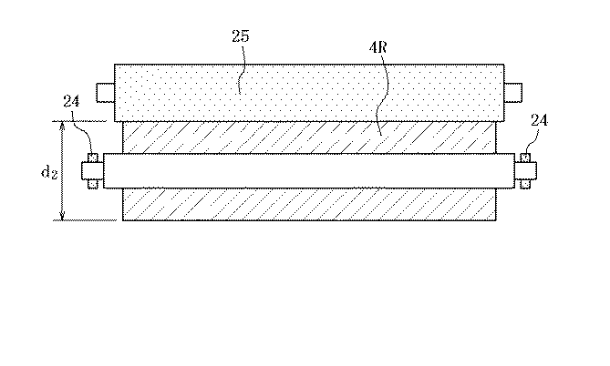
このあと、未研磨の弾性層が周囲に形成された芯金3を取り出し、図5に示すように、芯金3の両方の軸端部2をチャック24で把持して、芯金3を回転させながら、幅広砥石25を回転させて弾性層4Rの周面を研削することにより、所定の外径d2を有する弾性層4を形成し、弾性ローラを完成させる。
Thereafter, the
上記の工程において、本発明は、軸端部2を形成するに先立って、丸棒素材20の周面11を検査し、軸方向うねりにおけるWCM(ろ波最大うねり))が所定の値以下であるか否かをチェックし、このチェックで合格したものだけを次の、軸端部2を形成する工程に移す点に特徴があり、このことによって、軸端部2の振れを小さくすることができ、その結果、軸端部2の周面12を把持して行われる弾性層4の研磨において、弾性層の外径の振れを大幅に抑制することができる。
In the above process, the present invention inspects the
具体的には、本発明の弾性ローラは、弾性層4の外周面14における振れを30μm以下に収めるため、丸棒素材20の軸方向うねりの値を、WCM(ろ波最大うねり)で6μm以下とするものであり、このことによって、弾性層の周面14における振れが30μmを越えてスペックアウトとなることによる不良率を大幅に低減することができる。そして、この場合、弾性層の振れに直接影響を与える軸端部2の周面12における振れを15μm以下とするのが好ましい。
Specifically, since the elastic roller of the present invention keeps the deflection on the outer
本発明は、丸棒素材を形成する際、前記ロール矯正機で矯正を行う工程において、丸棒素材の表面に軸方向のうねりを多少なりとも発生し、このうねりが大きい場合と小さい場合とで、弾性層の振れの大きさが異なることを発明者が見出したことによってなされたものであり、発明者による詳細な調査の結果、より具体的には、弾性層の振れを30μm以下とするためには、丸棒素材20における軸方向うねりの値を、WCM(ろ波最大うねり)で6μm以下とすることが必須であることが判ったものである。
In the present invention, when forming a round bar material, in the process of correcting with the roll straightening machine, some axial waviness is generated on the surface of the round bar material. The inventor found out that the magnitude of the elastic layer shake differs, and as a result of detailed investigation by the inventor, more specifically, to make the elastic layer run out to 30 μm or less. It has been found that it is essential that the value of the axial waviness of the
ここで、周方向のうねりとは、JIS B0610で定義されるものであり、測定方法もそれに従うものとする。また、振れとは、回転体をその中心軸線の周りに回したとき
その周面の最大半径と最小半径との差である。
Here, the waviness in the circumferential direction is defined by JIS B0610, and the measurement method is also in accordance with it. Further, the shake is a difference between the maximum radius and the minimum radius of the peripheral surface when the rotating body is rotated around its central axis.
図1に示した構造の、芯金3の周囲に弾性層4を形成した非磁性現像ローラに関し、1ロットを500本として、1ロット中すべてのローラについて、芯金の本体部の長さ方向うねりの値を、WCM(ろ波最大うねり)で6μm以下としたロットを実施例として、1ロット中すべてのローラについて、芯金の本体部の長さ方向うねりの値が、Wcm(最大3波最大うねり)で6μmを越えるものとしたロットを比較例として、これらのロットについて、弾性層の平均振れを測定するとともに、振れが30μm以下のものを合格とする判定基準における不良率を計算し、それらのロット同士を比較した。表1にその結果を示す。
With respect to the non-magnetic developing roller having the structure shown in FIG. 1 and the elastic layer 4 formed around the
なお、実験に供した現像ローラは、芯金本体部1の外径d0が8.0mm、軸端部2の外径d1は6.0mm、芯金3の全長lは330mm、弾性層4の研磨後の外径d2は20mmであった。なお、表1において、最大値、最小値、平均値は、各ロットにおけるそれぞれのローラについての測定値を統計処理した際の最大値、最小値、平均値を表す。
1 芯金本体部
2 軸端部
3 芯金
4、4R 弾性層
6a〜6d 支持部材
9 フランジ部
11 丸棒素材の周面
12 軸端の周面
14 弾性層の外周面
20 丸棒素材
21 チャック
22 金型
23 キャップ
24 チャック
25 幅広砥石
26 注入口
29 キャビティ
DESCRIPTION OF
11
Claims (4)
前記芯金の丸棒素材部分の長さ方向うねりの値を、WCM(ろ波最大うねり)で6μm以下としてなる弾性ローラ。 A cored bar formed by machining both ends of a predetermined length of a round bar material formed by continuous drawing to form a shaft end of a circular cross section, and an elastic formed by forming an elastic layer around the cored bar In Laura
An elastic roller in which the value of waviness in the length direction of the round bar material portion of the core metal is set to 6 μm or less by WCM (maximum wave waviness).
前記連続引き抜き加工により形成した丸棒素材の所定長さに加工されたものから、軸方向うねりが所定の値以下のものだけを選別し、選別された丸棒素材の周面を把持して両端部を機械加工して軸端部を形成し、次いで、両軸端部の周面を把持して弾性層の周面を研磨する弾性ローラの製造方法。 In the method of manufacturing the elastic roller according to claim 1 or 2,
From the round bar material formed by the above-mentioned continuous drawing process, only those having an axial undulation below a predetermined value are selected from those processed to a predetermined length, and both ends are gripped by the peripheral surface of the selected round bar material. A method for manufacturing an elastic roller, in which a shaft end portion is formed by machining a portion, and then the peripheral surfaces of both shaft end portions are gripped to polish the peripheral surface of the elastic layer.
Priority Applications (1)
| Application Number | Priority Date | Filing Date | Title |
|---|---|---|---|
| JP2007134037A JP5134863B2 (en) | 2007-05-21 | 2007-05-21 | Manufacturing method of conductive roller |
Applications Claiming Priority (1)
| Application Number | Priority Date | Filing Date | Title |
|---|---|---|---|
| JP2007134037A JP5134863B2 (en) | 2007-05-21 | 2007-05-21 | Manufacturing method of conductive roller |
Publications (2)
| Publication Number | Publication Date |
|---|---|
| JP2008287152A true JP2008287152A (en) | 2008-11-27 |
| JP5134863B2 JP5134863B2 (en) | 2013-01-30 |
Family
ID=40146899
Family Applications (1)
| Application Number | Title | Priority Date | Filing Date |
|---|---|---|---|
| JP2007134037A Expired - Fee Related JP5134863B2 (en) | 2007-05-21 | 2007-05-21 | Manufacturing method of conductive roller |
Country Status (1)
| Country | Link |
|---|---|
| JP (1) | JP5134863B2 (en) |
Cited By (4)
| Publication number | Priority date | Publication date | Assignee | Title |
|---|---|---|---|---|
| JP2018069740A (en) * | 2018-01-19 | 2018-05-10 | ニッカ株式会社 | Cleaning cloth roll |
| CN108535975A (en) * | 2017-03-01 | 2018-09-14 | 柯尼卡美能达株式会社 | Charging system and image forming apparatus |
| JP2020160161A (en) * | 2019-03-25 | 2020-10-01 | 富士ゼロックス株式会社 | Conductive members, charging devices, transfer devices, process cartridges, and image forming devices |
| CN117001430A (en) * | 2023-07-26 | 2023-11-07 | 首钢京唐钢铁联合有限责任公司 | A method and device for evaluation and grinding of rolls |
Citations (10)
| Publication number | Priority date | Publication date | Assignee | Title |
|---|---|---|---|---|
| JPH0874839A (en) * | 1994-09-06 | 1996-03-19 | Canon Inc | Developing sleeve with shaft and manufacturing method thereof |
| JPH08185054A (en) * | 1994-12-28 | 1996-07-16 | Canon Inc | Developing sleeve having uniform fine uneven surface shape and manufacturing method thereof |
| JP2000127006A (en) * | 1998-10-20 | 2000-05-09 | Canon Inc | Manufacturing method of cylindrical member, developing device and image forming apparatus provided with this cylindrical member |
| JP2000293030A (en) * | 1999-04-02 | 2000-10-20 | Canon Inc | Developer carrier and developing device |
| JP2001022177A (en) * | 1999-07-06 | 2001-01-26 | Canon Inc | Developing roller |
| JP2001248630A (en) * | 2000-03-02 | 2001-09-14 | Tokai Rubber Ind Ltd | Semi-conductive roll |
| JP2001312140A (en) * | 2000-05-01 | 2001-11-09 | Shigekazu Kato | Roll for electronic apparatus and method for manufacturing the same |
| JP2004037663A (en) * | 2002-07-01 | 2004-02-05 | Ricoh Co Ltd | Developing roller and developing device having the same |
| JP2004276051A (en) * | 2003-03-13 | 2004-10-07 | Showa Denko Kk | Bar-shaped base stock for cutting, method for manufacturing it and bar-shaped cut goods |
| JP2004333638A (en) * | 2003-05-01 | 2004-11-25 | Ricoh Co Ltd | Toner carrier and method of manufacturing the same |
-
2007
- 2007-05-21 JP JP2007134037A patent/JP5134863B2/en not_active Expired - Fee Related
Patent Citations (10)
| Publication number | Priority date | Publication date | Assignee | Title |
|---|---|---|---|---|
| JPH0874839A (en) * | 1994-09-06 | 1996-03-19 | Canon Inc | Developing sleeve with shaft and manufacturing method thereof |
| JPH08185054A (en) * | 1994-12-28 | 1996-07-16 | Canon Inc | Developing sleeve having uniform fine uneven surface shape and manufacturing method thereof |
| JP2000127006A (en) * | 1998-10-20 | 2000-05-09 | Canon Inc | Manufacturing method of cylindrical member, developing device and image forming apparatus provided with this cylindrical member |
| JP2000293030A (en) * | 1999-04-02 | 2000-10-20 | Canon Inc | Developer carrier and developing device |
| JP2001022177A (en) * | 1999-07-06 | 2001-01-26 | Canon Inc | Developing roller |
| JP2001248630A (en) * | 2000-03-02 | 2001-09-14 | Tokai Rubber Ind Ltd | Semi-conductive roll |
| JP2001312140A (en) * | 2000-05-01 | 2001-11-09 | Shigekazu Kato | Roll for electronic apparatus and method for manufacturing the same |
| JP2004037663A (en) * | 2002-07-01 | 2004-02-05 | Ricoh Co Ltd | Developing roller and developing device having the same |
| JP2004276051A (en) * | 2003-03-13 | 2004-10-07 | Showa Denko Kk | Bar-shaped base stock for cutting, method for manufacturing it and bar-shaped cut goods |
| JP2004333638A (en) * | 2003-05-01 | 2004-11-25 | Ricoh Co Ltd | Toner carrier and method of manufacturing the same |
Cited By (6)
| Publication number | Priority date | Publication date | Assignee | Title |
|---|---|---|---|---|
| CN108535975A (en) * | 2017-03-01 | 2018-09-14 | 柯尼卡美能达株式会社 | Charging system and image forming apparatus |
| JP2018146612A (en) * | 2017-03-01 | 2018-09-20 | コニカミノルタ株式会社 | Charing device and image forming apparatus |
| JP2018069740A (en) * | 2018-01-19 | 2018-05-10 | ニッカ株式会社 | Cleaning cloth roll |
| JP2020160161A (en) * | 2019-03-25 | 2020-10-01 | 富士ゼロックス株式会社 | Conductive members, charging devices, transfer devices, process cartridges, and image forming devices |
| JP7255275B2 (en) | 2019-03-25 | 2023-04-11 | 富士フイルムビジネスイノベーション株式会社 | Conductive member, charging device, transfer device, process cartridge, and image forming apparatus |
| CN117001430A (en) * | 2023-07-26 | 2023-11-07 | 首钢京唐钢铁联合有限责任公司 | A method and device for evaluation and grinding of rolls |
Also Published As
| Publication number | Publication date |
|---|---|
| JP5134863B2 (en) | 2013-01-30 |
Similar Documents
| Publication | Publication Date | Title |
|---|---|---|
| JP6002842B2 (en) | Drive mechanism with metal belt | |
| JP5134863B2 (en) | Manufacturing method of conductive roller | |
| JP2007054917A (en) | Method for manufacturing rubber roll and rubber roll | |
| US7631530B2 (en) | Aluminum pipe production method | |
| CN101101463B (en) | Elastic roller and grinding method for the same | |
| JP2000122310A (en) | Production of mirror surface pipe for photorecertive drum of copying machine or the like | |
| JPH0743922A (en) | Production of aluminum pipe for electrophotographic photoreceptor | |
| JP5046498B2 (en) | Rubber roll grinding method and rubber roll | |
| JP2009142957A (en) | Method for manufacturing pipe with flange member | |
| JP2009169158A (en) | Method for producing electrophotographic photosensitive member and electrophotographic photosensitive member | |
| KR100461342B1 (en) | Manufacturing method and a burnishing apparatus for a development roller | |
| JPH10156841A (en) | Elastic roller and manufacture thereof | |
| JP2004136378A (en) | Precision polishing method to outer peripheral surface of elastic roller | |
| JP2004195606A (en) | Rubber roll manufacturing method | |
| JP2004074429A (en) | Mold for molding rubber roller and manufacturing method for rubber roller | |
| JP2006095639A (en) | Grinding method of rubber roll and rubber roll | |
| JP2009072877A (en) | Rubber roll and its manufacturing method | |
| CN120116030A (en) | A grinding method for low-hardness sleeve parts | |
| JP2007000953A (en) | Manufacturing method of rubber roll and rubber roll | |
| JP5700264B2 (en) | Wafer edge processing apparatus and edge processing method thereof | |
| JP2007310021A (en) | Tube for photosensitive drum | |
| JPH11254284A (en) | Inner surface polishing method of sanitary stainless steel pipe | |
| JP2004276172A (en) | Grinding method and method of manufacturing grinding wheel | |
| JP3032957U (en) | Equipment for polishing developing sleeves for copiers, printers, etc. | |
| KR100476766B1 (en) | Roller of printer system and manufacturing method thereof |
Legal Events
| Date | Code | Title | Description |
|---|---|---|---|
| A621 | Written request for application examination |
Free format text: JAPANESE INTERMEDIATE CODE: A621 Effective date: 20100520 |
|
| A131 | Notification of reasons for refusal |
Free format text: JAPANESE INTERMEDIATE CODE: A131 Effective date: 20120508 |
|
| A521 | Written amendment |
Free format text: JAPANESE INTERMEDIATE CODE: A523 Effective date: 20120709 |
|
| A131 | Notification of reasons for refusal |
Free format text: JAPANESE INTERMEDIATE CODE: A131 Effective date: 20120731 |
|
| A521 | Written amendment |
Free format text: JAPANESE INTERMEDIATE CODE: A523 Effective date: 20120928 |
|
| TRDD | Decision of grant or rejection written | ||
| A01 | Written decision to grant a patent or to grant a registration (utility model) |
Free format text: JAPANESE INTERMEDIATE CODE: A01 Effective date: 20121016 |
|
| A01 | Written decision to grant a patent or to grant a registration (utility model) |
Free format text: JAPANESE INTERMEDIATE CODE: A01 |
|
| A61 | First payment of annual fees (during grant procedure) |
Free format text: JAPANESE INTERMEDIATE CODE: A61 Effective date: 20121112 |
|
| FPAY | Renewal fee payment (event date is renewal date of database) |
Free format text: PAYMENT UNTIL: 20151116 Year of fee payment: 3 |
|
| R150 | Certificate of patent or registration of utility model |
Free format text: JAPANESE INTERMEDIATE CODE: R150 Ref document number: 5134863 Country of ref document: JP Free format text: JAPANESE INTERMEDIATE CODE: R150 |
|
| R250 | Receipt of annual fees |
Free format text: JAPANESE INTERMEDIATE CODE: R250 |
|
| R250 | Receipt of annual fees |
Free format text: JAPANESE INTERMEDIATE CODE: R250 |
|
| R250 | Receipt of annual fees |
Free format text: JAPANESE INTERMEDIATE CODE: R250 |
|
| R250 | Receipt of annual fees |
Free format text: JAPANESE INTERMEDIATE CODE: R250 |
|
| LAPS | Cancellation because of no payment of annual fees |