JP2008233533A - Optical film, polarizing plate and image display device - Google Patents
Optical film, polarizing plate and image display device Download PDFInfo
- Publication number
- JP2008233533A JP2008233533A JP2007072933A JP2007072933A JP2008233533A JP 2008233533 A JP2008233533 A JP 2008233533A JP 2007072933 A JP2007072933 A JP 2007072933A JP 2007072933 A JP2007072933 A JP 2007072933A JP 2008233533 A JP2008233533 A JP 2008233533A
- Authority
- JP
- Japan
- Prior art keywords
- optical film
- copolymer
- polarizing plate
- film
- mass
- Prior art date
- Legal status (The legal status is an assumption and is not a legal conclusion. Google has not performed a legal analysis and makes no representation as to the accuracy of the status listed.)
- Withdrawn
Links
Images


Landscapes
- Polarising Elements (AREA)
- Liquid Crystal (AREA)
- Manufacture Of Macromolecular Shaped Articles (AREA)
- Compositions Of Macromolecular Compounds (AREA)
Abstract
【課題】ヘーズが小さく透明性に優れ、複屈折の低い等の光学特性に優れ、良好な機械強度および耐熱性を有し、透湿性に優れる光学フィルムを提供すること。
【解決手段】(A)下記一般式(I)で表される環状オレフィン共重合体70〜97質量%、及び(B)オレフィンの二元又は三元共重合体3〜30質量%を含有する樹脂組成物からなる光学フィルムである。

・・・(I)
【選択図】なしAn optical film having excellent optical properties such as low haze, excellent transparency, low birefringence, good mechanical strength and heat resistance, and excellent moisture permeability is provided.
SOLUTION: (A) 70 to 97% by mass of a cyclic olefin copolymer represented by the following general formula (I), and (B) 3 to 30% by mass of an olefin binary or ternary copolymer. An optical film made of a resin composition.
... (I)
[Selection figure] None
Description
本発明は、ヘーズが小さく透明性に優れ、複屈折が低く、かつ光弾性定数が小さい等の光学特性に優れ、良好な機械強度、可撓性及び耐熱性を有した光学フィルム、及び該フィルムを偏光子の片面又は両面に保護膜として利用した偏光板、並びに該偏光板を用いた画像表示装置に関する。 The present invention relates to an optical film having excellent mechanical properties, flexibility and heat resistance, excellent optical properties such as low haze, excellent transparency, low birefringence, and low photoelastic constant, and the film The present invention relates to a polarizing plate using a protective film on one or both sides of a polarizer, and an image display device using the polarizing plate.
偏光板は、特定の振動方向をもつ光のみを透過させ、その他の光を遮蔽する機能を有する材料であり、例えば液晶表示装置を構成する部品の一つとして広く使用されている。このような偏光板としては、偏光子と保護フィルムが積層された構成をもつものが一般的に使用されている。前記偏光子は、特定の振動方向をもつ光のみを透過する機能を有するものであり、例えばポリビニルアルコール(以下「PVA」と記す。)フィルム等を延伸し、ヨウ素や二色性染料などで染色したフィルムが一般に使用されている。また、最近では塗布型の偏光子も用いられている。 The polarizing plate is a material having a function of transmitting only light having a specific vibration direction and shielding other light, and is widely used as one of components constituting a liquid crystal display device, for example. As such a polarizing plate, what has the structure on which the polarizer and the protective film were laminated | stacked is generally used. The polarizer has a function of transmitting only light having a specific vibration direction. For example, a polyvinyl alcohol (hereinafter referred to as “PVA”) film is stretched and dyed with iodine or a dichroic dye. The film is generally used. Recently, a coating-type polarizer is also used.
ところで、前記保護フィルムとは、偏光子を保持して偏光板全体に実用的な強度を付与するなどの機能を担うものであり、例えばセルロース系フィルムのトリアセチルセルロース(以下「TAC」と記す。)フィルムなどが一般に使用されている。セルロース系フィルムは、透明性が良好で、複屈折が小さいなど光学的な均一性に優れ、実用的な耐熱性と優れた機械強度を持っているため偏光子保護フィルムとして優れた特性を有している。
また、透湿度が高いためPVAなどの偏光子と貼り合わせる際に、PVAや接着剤の水分透過性に優れるなど加工性も良いため、偏光子保護フィルムとして一般的に用いられている(例えば、特許文献1参照)。
しかし、セルロース系フィルム(例えばTACフィルム)は吸水性も高いため、偏光子の性能低下、吸水による寸法安定性などに問題があった。
By the way, the said protective film bears functions, such as holding a polarizer and giving practical intensity | strength to the whole polarizing plate, for example, writes triacetyl cellulose (henceforth "TAC") of a cellulose-type film. ) Film is generally used. Cellulose film has excellent properties as a polarizer protective film because it has excellent optical uniformity such as good transparency and low birefringence, practical heat resistance and excellent mechanical strength. ing.
In addition, since it has high moisture permeability, when it is bonded to a polarizer such as PVA, it is generally used as a polarizer protective film because it has good workability such as excellent moisture permeability of PVA and adhesive (for example, Patent Document 1).
However, since the cellulose-based film (for example, TAC film) has high water absorption, there have been problems such as deterioration in performance of the polarizer and dimensional stability due to water absorption.
そこで、従来のTACフィルムよりも吸水率の小さいフィルム素材を偏光子保護フィルムとして用いることにより、寸法安定性を向上しようとする試みがなされている。しかしながら、吸水性の小さなポリカーボネートフィルムやポリエチレンテレフタレートフィルムは、光弾性定数が大きく、外部応力の作用によって位相差の変化が生じるため偏光板としての性能低下を生じてしまうという問題があった。 Thus, attempts have been made to improve dimensional stability by using a film material having a smaller water absorption rate than the conventional TAC film as a polarizer protective film. However, a polycarbonate film or polyethylene terephthalate film having a small water absorption has a problem that the photoelastic constant is large and the phase difference is changed by the action of external stress, so that the performance as a polarizing plate is deteriorated.
また、耐摩擦性、透明性、柔軟性に優れた組成物として、オレフィン樹脂、プロピレン共重合体及びゴム成分を含有してなる熱可塑性エラストマー組成物が提案されている(特許文献2参照)。
しかし、偏光子保護膜として、上記熱可塑性エラストマーを単体で使用した場合には、単体で伸びが発生しやすいという欠点があり、また、等方性材料であっても、製膜時に延伸され配向され、面内位相差が10nmより高くなり、偏光板としての機能に問題が発生する。
Further, a thermoplastic elastomer composition containing an olefin resin, a propylene copolymer, and a rubber component has been proposed as a composition excellent in friction resistance, transparency, and flexibility (see Patent Document 2).
However, when the thermoplastic elastomer is used alone as a polarizer protective film, there is a drawback that it tends to be stretched alone, and even an isotropic material is stretched and oriented during film formation. Then, the in-plane retardation becomes higher than 10 nm, and a problem occurs in the function as a polarizing plate.
また、低吸水性、防湿性、低複屈折等の特徴を有する環状ポリオレフィンフィルムが提案されている(特許文献3、4及び5参照)。
しかし、偏光板保護膜として上記環状ポリオレフィンフィルムを単体で使用した場合、柔軟性がなく、脆くて割れやすいという問題点があった。また、アイオノマーと環状ポリオレフィンを混練して作製したフィルムにおいては、アイオノマーと環状ポリオレフィンが混練しにくいという問題点があった。
In addition, a cyclic polyolefin film having features such as low water absorption, moisture resistance, and low birefringence has been proposed (see
However, when the above cyclic polyolefin film is used alone as a polarizing plate protective film, there is a problem that it is not flexible and is brittle and easily cracked. Further, a film prepared by kneading an ionomer and a cyclic polyolefin has a problem that the ionomer and the cyclic polyolefin are difficult to knead.
本発明は上記問題点に鑑み、ヘーズが小さく透明性に優れ、複屈折が低く、光弾性定数が小さい等の光学特性に優れ、良好な機械強度および耐熱性を有した光学フィルム、該光学フィルムを用いた偏光板及び偏光板を用いた画像表示装置を提供することを目的とする。 In view of the above problems, the present invention is an optical film having excellent mechanical properties and heat resistance, excellent optical properties such as low haze, excellent transparency, low birefringence, and low photoelastic constant, and the optical film. An object of the present invention is to provide a polarizing plate using, and an image display device using the polarizing plate.
本発明者らは、前記目的を達成するために鋭意研究を重ねた結果、特定の構造を有する環状オレフィン共重合体とオレフィンの二元又は三元共重合体を含有する樹脂組成物からなる光学フィルムを用いることで上記課題を解決し得ることを見出した。
すなわち、本発明は、
[1] (A)下記一般式(I)で表される環状オレフィン共重合体70〜97質量%、及び(B)オレフィンの二元又は三元共重合体3〜30質量%を含有する樹脂組成物からなる光学フィルム、
(式中、R1は置換基Qを有していてもよい炭素数1〜20の2価の炭化水素基、R2は水素原子又は炭素数1〜10の1価の炭化水素基、R3は炭素数2〜10の4価の炭化水素基、QはCOOR4(R4は水素原子又は炭素数1〜10の1価の炭化水素基、Qが複数ある場合はそれぞれが同一でも異なってもよい)で示されるカルボキシル基又はアルコキシカルボニル基、nは0〜20の整数、x及びyは0/100≦y/x≦95/5の関係を満たす実数である。)
[2]前記(B)成分が以下の成分(a)、(b)及び(c)からなる群から選ばれる少なくとも2種のモノマーの共重合体である上記[1]に記載の光学フィルム、
(a)オレフィン
(b)α,β−不飽和カルボン酸、その無水物及びα,β−不飽和カルボン酸グリシジルエステルからなる群から選ばれる不飽和カルボン酸
(c)不飽和エステル
[3]前記(B)成分がプロピレン−α−オレフィン共重合体である上記[1]に記載の光学フィルム、
[4]前記(B)成分がプロピレンと1−ブテンのランダム共重合体、エチレン−アクリル酸共重合体、及びエチレン−無水マレイン酸−アクリル酸エステル共重合体からなる群から選ばれる少なくとも1種である上記[1]に記載の光学フィルム、
[5]光弾性定数が5×10-12/Pa以下である上記[1]〜[4]のいずれかに記載の光学フィルム、
[6]上記[1]〜[5]のいずれかに記載の光学フィルムを偏光子の少なくとも片面に形成してなる偏光板、及び
[7]上記[6]に記載の偏光板を用いてなる画像表示装置、
を提供するものである。
As a result of intensive studies to achieve the above object, the present inventors have found that an optical component comprising a resin composition containing a cyclic olefin copolymer having a specific structure and a binary or ternary copolymer of olefins. It has been found that the above problems can be solved by using a film.
That is, the present invention
[1] (A) Resin containing 70 to 97% by mass of cyclic olefin copolymer represented by the following general formula (I) and (B) 3 to 30% by mass of olefin binary or ternary copolymer An optical film comprising the composition,
(In the formula, R 1 is a divalent hydrocarbon group having 1 to 20 carbon atoms which may have a substituent Q, R 2 is a hydrogen atom or a monovalent hydrocarbon group having 1 to 10 carbon atoms, R 3 is a tetravalent hydrocarbon group having 2 to 10 carbon atoms, Q is COOR 4 (R 4 is a hydrogen atom or a monovalent hydrocarbon group having 1 to 10 carbon atoms, and when there are a plurality of Q, each is the same or different. And n is an integer of 0 to 20, and x and y are real numbers satisfying the relationship of 0/100 ≦ y / x ≦ 95/5.)
[2] The optical film as described in [1] above, wherein the component (B) is a copolymer of at least two monomers selected from the group consisting of the following components (a), (b) and (c):
(A) an olefin (b) an α, β-unsaturated carboxylic acid, an anhydride thereof, and an unsaturated carboxylic acid (c) an unsaturated ester selected from the group consisting of an α, β-unsaturated carboxylic acid glycidyl ester [3] (B) The optical film as described in [1] above, wherein the component is a propylene-α-olefin copolymer,
[4] The component (B) is at least one selected from the group consisting of a random copolymer of propylene and 1-butene, an ethylene-acrylic acid copolymer, and an ethylene-maleic anhydride-acrylic acid ester copolymer. The optical film according to the above [1],
[5] The optical film according to any one of [1] to [4], wherein the photoelastic constant is 5 × 10 −12 / Pa or less,
[6] A polarizing plate formed by forming the optical film according to any one of [1] to [5] on at least one surface of a polarizer, and [7] the polarizing plate according to [6]. Image display device,
Is to provide.
本発明の光学フィルムは、ヘーズが小さく透明性に優れ、複屈折が低く、光弾性定数が小さい等の光学特性に優れ、良好な機械強度及び耐熱性を有し、透湿性に優れる。また、耐熱性、耐湿熱性、耐冷熱サイクル等の各種耐久性に優れ、また偏光板の光学的機能に何ら影響を与えることなく、しかも、柔軟でかつ弾性に富む。なお、本発明の光学フィルムは、外部からの衝撃や変形に対し抵抗力を有するため、偏光子に貼り合わせることで、液晶表示素子としての強度や信頼性を顕著に向上させた偏光板が得られる。
さらに、本発明の光学フィルムは、従来汎用されているTACフィルムと比較した場合、これと同等以上の保護機能を有する。特にTACフィルムは親水性であり、防湿性が殆んどないのに対し、本発明の光学フィルムは疎水性であるので、偏光板の耐久性を大幅に向上させることができる。従って、本発明の光学フィルムは、偏光板の一面に積層されて液晶セル表面基板と接着される保護膜として好適に使用でき、偏光板の他面側の保護膜に使用することもできる。
The optical film of the present invention has excellent optical properties such as low haze, excellent transparency, low birefringence, and low photoelastic constant, good mechanical strength and heat resistance, and excellent moisture permeability. Further, it is excellent in various durability such as heat resistance, heat and humidity resistance, and a heat and cold cycle, and has no influence on the optical function of the polarizing plate, and is flexible and rich in elasticity. In addition, since the optical film of the present invention has resistance to external impacts and deformations, a polarizing plate with significantly improved strength and reliability as a liquid crystal display element can be obtained by bonding to a polarizer. It is done.
Furthermore, the optical film of the present invention has a protective function equivalent to or higher than that of a conventionally used TAC film. In particular, the TAC film is hydrophilic and hardly moisture proof, whereas the optical film of the present invention is hydrophobic, so that the durability of the polarizing plate can be greatly improved. Therefore, the optical film of the present invention can be suitably used as a protective film laminated on one surface of the polarizing plate and bonded to the liquid crystal cell surface substrate, and can also be used as a protective film on the other surface side of the polarizing plate.
本発明の光学フィルムは、(A)特定の構造の環状オレフィン共重合体70〜97質量%、及び(B)オレフィンの二元又は三元共重合体3〜30質量%を含有する樹脂組成物からなる。 The optical film of the present invention comprises (A) 70 to 97% by mass of a cyclic olefin copolymer having a specific structure, and (B) 3 to 30% by mass of an olefin binary or ternary copolymer. Consists of.
[(A)環状オレフィン共重合体]
本発明で用いられる環状オレフィン共重合体は下記一般式(I)で示される。
[(A) Cyclic olefin copolymer]
The cyclic olefin copolymer used in the present invention is represented by the following general formula (I).
上記式(I)中、R1は置換基Qを有していてもよい炭素数1〜20の2価の炭化水素基である。R1が少なくとも1つの環構造を持つことが好ましい。QはCOOR4で示されるカルボキシル基又はアルコキシカルボニル基であり、Qが複数ある場合はそれぞれが同一でも異なってもよい。R4は水素原子又は炭素数1〜10の1価の炭化水素基であるが、これらのうち、特にR4が水素又はメチル基である場合が好ましい。
次に、R2は水素原子又は炭素数1〜10の1価の炭化水素基であり、R3は炭素数2〜10の4価の炭化水素基である。nは0〜20の整数を示すが、0である場合が最も好ましい。x及びyは共重合比を示し、0/100≦y/x≦95/5の関係を満たす実数であり、さらに20/80≦y/x≦85/15の関係を満たすことが好ましい。
In the above formula (I), R 1 is a divalent hydrocarbon group having 1 to 20 carbon atoms that may have a substituent Q. R 1 preferably has at least one ring structure. Q is a carboxyl group or an alkoxycarbonyl group represented by COOR 4 , and when there are a plurality of Q, each may be the same or different. R 4 is a hydrogen atom or a monovalent hydrocarbon group having 1 to 10 carbon atoms, and among these, particularly preferred is a case where R 4 is hydrogen or a methyl group.
Next, R 2 is a hydrogen atom or a monovalent hydrocarbon group having 1 to 10 carbon atoms, and R 3 is a tetravalent hydrocarbon group having 2 to 10 carbon atoms. n represents an integer of 0 to 20, and is most preferably 0. x and y represent copolymerization ratios, are real numbers that satisfy the relationship of 0/100 ≦ y / x ≦ 95/5, and preferably satisfy the relationship of 20/80 ≦ y / x ≦ 85/15.
上記式(I)で示される環状オレフィン共重合体は、少なくともR3が環状構造を有するか又はR1及びR3によって環状構造を構成するものである。これらの環状オレフィン共重合体は1種を単独で、又は2種以上を併用することができる。
上記式(I)で示される環状オレフィン共重合体のより好ましい態様としては、下記一般式(II)で示される構造のものを挙げることができる。
In the cyclic olefin copolymer represented by the above formula (I), at least R 3 has a cyclic structure, or R 1 and R 3 constitute a cyclic structure. These cyclic olefin copolymers can be used alone or in combination of two or more.
A more preferable embodiment of the cyclic olefin copolymer represented by the above formula (I) includes a structure represented by the following general formula (II).
上記式(II)において、R1は上述したとおりである。また、R2は上述のように、水素原子又は炭素数1〜10の1価の炭化水素基であり、好ましくは水素原子又は炭素数1〜5の1価の炭化水素基である。共重合比を示すx及びyは上述のとおりである。
上記式(II)において、R3は5員環構造を有する4価の炭化水素基であるが、この他に、下記式(III)及び(IV)で示される構造のものも好適に挙げられる。なお、R1については上記と同様である。
In the above formula (II), R 1 is as described above. R 2 is a hydrogen atom or a monovalent hydrocarbon group having 1 to 10 carbon atoms, preferably a hydrogen atom or a monovalent hydrocarbon group having 1 to 5 carbon atoms, as described above. X and y indicating the copolymerization ratio are as described above.
In the above formula (II), R 3 is a tetravalent hydrocarbon group having a five-membered ring structure. In addition to this, those having structures represented by the following formulas (III) and (IV) are also preferred. . R 1 is the same as described above.
また、他の好ましい態様としては、R1が下記式(V)で表されるものであり(式中、pは0〜2である)、R2が水素であるものが挙げられ、特にpが1の場合が好ましい。 Other preferred embodiments include those in which R 1 is represented by the following formula (V) (wherein p is 0 to 2), and R 2 is hydrogen. Is preferably 1.
さらに、本発明の(A)成分としては、エチレンとテトラシクロ[4.4.0.12,5.17,10]−3−ドデセンのランダム付加重合によって得られる共重合体が最も好ましい。
また、(A)環状オレフィン共重合体中のエチレンの含有量は15〜85モル%が好ましい。エチレン含有量が85モル%以下であると十分な耐熱性が得られる。一方、15モル%以上であると環状オレフィン共重合体の製造コストが安価となり好ましい。以上の点から、(A)環状オレフィン共重合体中のエチレンの含有量は20〜80モル%がさらに好ましい。
Furthermore, as the component (A) of the present invention, ethylene and tetracyclo [4.4.0.1 2,5 . Most preferred are copolymers obtained by random addition polymerization of 1 7,10 ] -3-dodecene.
Moreover, 15-85 mol% of content of ethylene in (A) cyclic olefin copolymer is preferable. Sufficient heat resistance is obtained when the ethylene content is 85 mol% or less. On the other hand, when it is 15 mol% or more, the production cost of the cyclic olefin copolymer is reduced, which is preferable. From the above points, the ethylene content in the (A) cyclic olefin copolymer is more preferably 20 to 80 mol%.
また、(A)成分における共重合のタイプは本発明において全く制限されるものではなく、ランダム共重合体、ブロック共重合体、交互共重合等、公知の様々な共重合タイプを適用することができるが、透明性の点からランダム共重合体が好ましい。 Further, the type of copolymerization in component (A) is not limited at all in the present invention, and various known copolymerization types such as random copolymer, block copolymer, alternating copolymerization, etc. can be applied. However, a random copolymer is preferable from the viewpoint of transparency.
また、本発明の効果を損なわない範囲であれば、(A)成分を構成するコモノマーとして、上記したもの以外の他のモノマーを含めることができる。他のモノマーの共重合比は限定されないが、十分な耐熱性を得るとの観点から、通常は20モル%以下、好ましくは10モル%以下である。 Moreover, if it is a range which does not impair the effect of this invention, other monomers other than what was mentioned above can be included as a comonomer which comprises (A) component. The copolymerization ratio of other monomers is not limited, but is usually 20 mol% or less, preferably 10 mol% or less from the viewpoint of obtaining sufficient heat resistance.
本発明の(A)環状オレフィン共重合体の分子量は限定されるものではないが、好ましくはメルトフローレイト(以下「MFR」と記す)が、0.01≦MFR≦150g/10min(260℃)、さらに好ましくは0.1≦MFR≦100g/10minであり、最も好ましくは0.5≦MFR≦70g/10minである。MFRが0.01g/10minより高い場合、良好な成形性を得ることができ、また、MFRが150g/10minより低ければ、靭性などの機械物性を損なうことがなく好ましい。 The molecular weight of the (A) cyclic olefin copolymer of the present invention is not limited, but preferably the melt flow rate (hereinafter referred to as “MFR”) is 0.01 ≦ MFR ≦ 150 g / 10 min (260 ° C.). More preferably, 0.1 ≦ MFR ≦ 100 g / 10 min, and most preferably 0.5 ≦ MFR ≦ 70 g / 10 min. When the MFR is higher than 0.01 g / 10 min, good moldability can be obtained, and when the MFR is lower than 150 g / 10 min, it is preferable without impairing mechanical properties such as toughness.
また、(A)環状オレフィン共重合体のガラス転移温度は60〜200℃の範囲のものが用いられ、中でも100〜200℃の範囲のものが好ましい。ガラス転移温度が60℃以上であれば、良好な耐熱性を得ることができる。また200℃以下であれば良好な溶融成形性を得ることができる。 The glass transition temperature of the (A) cyclic olefin copolymer is in the range of 60 to 200 ° C, and in particular, the glass transition temperature is preferably in the range of 100 to 200 ° C. If the glass transition temperature is 60 ° C. or higher, good heat resistance can be obtained. Moreover, if it is 200 degrees C or less, favorable melt moldability can be obtained.
本発明の樹脂組成物中の上記(A)成分の含有量は70〜97質量%の範囲である。(A)成分の含有量が70質量%より少ない場合は、光弾性定数が大きくなり、光学フィルムとして用いることは困難である。一方、(A)成分の含有量が97質量%を超えると樹脂組成物の柔軟性が無くなり脆くなる。以上の観点から、(A)成分の含有量は80〜95質量%の範囲がより好ましい。 Content of the said (A) component in the resin composition of this invention is the range of 70-97 mass%. When content of (A) component is less than 70 mass%, a photoelastic constant becomes large and it is difficult to use as an optical film. On the other hand, when the content of the component (A) exceeds 97% by mass, the resin composition becomes inflexible and becomes brittle. From the above viewpoint, the content of the component (A) is more preferably in the range of 80 to 95% by mass.
[(B)オレフィンの二元又は三元共重合体]
本発明の(B)成分である二元又は三元共重合体は、エチレン、プロピレン、1−ブテン等のオレフィンの共重合体、及びエチレン、プロピレン、1−ブテンなどのオレフィンとオレフィン以外の他のモノマーの共重合体を含むものである。
オレフィンの共重合体としては、エチレンとプロピレンの二元共重合体、エチレンと1−ブテンなどの炭素数4以上のα−オレフィンの二元共重合体、プロピレンと炭素数4以上のα−オレフィンの二元共重合体、エチレン−プロピレン−炭素数4以上のα−オレフィンの三元共重合体などが挙げられ、これらのうち、プロピレンと炭素数4以上のα−オレフィンの二元共重合体が好ましい。
炭素数4以上のオレフィンとしては、1−ブテン、1−ヘキセン、1−ペンテン、1−ヘプテン、オクテン−1、ノネン−1、デセン−1、4−メチルヘキセン−1、4,4−ジメチルペンテン−1、5−メチルヘプテン−1、6−メチルヘプテン−1、4−メチル−1−ブテン及び4−メチルペンテン−1から選ばれる少なくとも1種であることが好ましく、特に1−ブテンが好ましい。
[(B) olefin binary or ternary copolymer]
The binary or ternary copolymer which is the component (B) of the present invention is a copolymer of olefins such as ethylene, propylene and 1-butene, and other than olefins and olefins such as ethylene, propylene and 1-butene. The copolymer of the monomer of this is included.
Examples of the olefin copolymer include a binary copolymer of ethylene and propylene, a binary copolymer of α-olefin having 4 or more carbon atoms such as ethylene and 1-butene, and an α-olefin having propylene and 4 or more carbon atoms. And a terpolymer of ethylene-propylene-α-olefin having 4 or more carbon atoms. Among these, a binary copolymer of propylene and α-olefin having 4 or more carbon atoms. Is preferred.
Examples of the olefin having 4 or more carbon atoms include 1-butene, 1-hexene, 1-pentene, 1-heptene, octene-1, nonene-1, decene-1, 4-methylhexene-1, 4,4-dimethylpentene. -1,5-methylheptene-1,6-methylheptene-1,4-methyl-1-butene and 4-methylpentene-1 are preferable, and 1-butene is particularly preferable.
また、該共重合体はランダム共重合体でもブロック共重合体でもよいが、光学フィルムとしての透明性の保持の点からランダム共重合体がより好ましい。
すなわち、本発明の(B)成分としては、プロピレンと1−ブテンのランダム共重合体が特に好ましい。
The copolymer may be a random copolymer or a block copolymer, but a random copolymer is more preferable from the viewpoint of maintaining transparency as an optical film.
That is, as the component (B) of the present invention, a random copolymer of propylene and 1-butene is particularly preferable.
本発明で好適な態様であるプロピレン−α−オレフィン共重合体は通常以下のような方法で製造される。すなわち、管状反応器を用いるプロピレン単独重合を第1工程とする連続多段重合によって製造され、好ましくは、次の第1工程〜第3工程を連続的に実施することによって得られる。
(第1工程)管状反応器を用い、5〜40℃の重合温度にてプロピレン単独重合を行い、プロピレンホモポリマーを全質量の2〜15質量%製造する工程。
(第2工程)プロピレンとエチレンを共重合し、プロピレンとエチレンに由来する構成単位を有する共重合体を製造する工程。
(第3工程)プロピレンと、エチレン及び炭素数4以上のα−オレフィンから選ばれる少なくとも1種のオレフィンを共重合し、プロピレンとエチレンに由来する構成単位を有する共重合体、プロピレンと炭素数4以上のα−オレフィンに由来する構成単位を有する共重合体及びプロピレン、炭素数4以上のα−オレフィン及びエチレンに由来する構成単位を有する共重合体の少なくとも1種の共重合体を、前記第2工程で製造した、共重合体との合計量が、ポリプロピレン共重合体全質量の98〜85質量%となるように製造する工程。
The propylene-α-olefin copolymer which is a preferred embodiment in the present invention is usually produced by the following method. That is, it is produced by continuous multistage polymerization in which propylene homopolymerization using a tubular reactor is the first step, and is preferably obtained by continuously performing the following first to third steps.
(First step) A step of producing a propylene homopolymer in an amount of 2 to 15% by mass based on the total mass using a tubular reactor at a polymerization temperature of 5 to 40 ° C.
(2nd process) The process of copolymerizing a propylene and ethylene and manufacturing the copolymer which has a structural unit derived from a propylene and ethylene.
(Third step) A copolymer having a structural unit derived from propylene and ethylene by copolymerizing propylene with at least one olefin selected from ethylene and an α-olefin having 4 or more carbon atoms, propylene and 4 carbon atoms. A copolymer having a structural unit derived from the above α-olefin and at least one copolymer of propylene, an α-olefin having 4 or more carbon atoms and a copolymer having a structural unit derived from ethylene, The process of manufacturing so that the total amount with the copolymer manufactured by 2 processes may be 98-85 mass% of the polypropylene copolymer total mass.
本発明のプロピレン−α−オレフィン共重合体におけるプロピレンとα−オレフィンの含有比率は、プロピレン95〜50質量%に対して、α−オレフィンが5〜50質量%であることが耐熱性の点から好ましい。以上の観点から、プロピレン93〜60質量%に対して、α−オレフィンが7〜40質量%であることが更に好ましい。 From the heat-resistant point, the content ratio of propylene and α-olefin in the propylene-α-olefin copolymer of the present invention is 5 to 50% by mass of α-olefin with respect to 95 to 50% by mass of propylene. preferable. From the above viewpoint, the α-olefin is more preferably 7 to 40% by mass with respect to 93 to 60% by mass of propylene.
プロピレン−α−オレフィン共重合体の製造に際しての触媒としては、種々のチグラー系の触媒を用いることができるが、プロピレンの単独重合を行った時、高度にアイソタクチック構造か、あるいはシンジオタクチック構造の重合体を与えるような触媒系を用いてプロピレンとα−オレフィンを重合して得られる共重合体が好ましい。 As a catalyst for producing a propylene-α-olefin copolymer, various Ziegler type catalysts can be used. When propylene is homopolymerized, it has a highly isotactic structure or syndiotactic. A copolymer obtained by polymerizing propylene and an α-olefin using a catalyst system that gives a polymer having a structure is preferred.
重合に用いる触媒としては、具体的には3価あるいは4価のハロゲン化チタン、あるいはそれを種々の担体に担持した遷移金属触媒、あるいは2個の連結したシクロペンタジエニル基あるいはその誘導体を配位子として有するジルコニウム、ハフニウム、チタンなどのメタロセン化合物と有機金属化合物からなる触媒系が好ましく利用される。 Specific examples of the catalyst used for the polymerization include trivalent or tetravalent titanium halides, transition metal catalysts having these supported on various carriers, or two linked cyclopentadienyl groups or derivatives thereof. A catalyst system comprising a metallocene compound such as zirconium, hafnium, or titanium as an ligand and an organometallic compound is preferably used.
本発明の(B)成分である二元又は三元共重合体は、上述のように、エチレン、プロピレン、1−ブテンなどのオレフィンとオレフィン以外の他のモノマーの共重合体を含むが、これらのうち、オレフィンとカルボキシル基やアルコキシカルボニル基などの官能基を有するモノマーとの共重合体、いわゆる変成オレフィン共重合体が好ましい。例えば、(a)オレフィン、(b)α,β−不飽和カルボン酸、その無水物及びα,β−不飽和カルボン酸グリシジルエステルからなる群から選ばれる不飽和カルボン酸及び(c)不飽和エステルをモノマーとした二元共重合体及び三元共重合体などが挙げられる。
これらの変成オレフィン共重合体は、ランダム共重合体でもブロック共重合体でもよいが、光学フィルムとしての透明性の保持の点からランダム共重合体がより好ましい。
The binary or ternary copolymer as the component (B) of the present invention includes a copolymer of an olefin such as ethylene, propylene, and 1-butene and a monomer other than the olefin as described above. Among these, a copolymer of an olefin and a monomer having a functional group such as a carboxyl group or an alkoxycarbonyl group, a so-called modified olefin copolymer is preferable. For example, (a) an olefin, (b) an α, β-unsaturated carboxylic acid, its anhydride, and an α, β-unsaturated carboxylic acid glycidyl ester, and (c) an unsaturated ester Examples thereof include binary copolymers and ternary copolymers using as a monomer.
These modified olefin copolymers may be random copolymers or block copolymers, but random copolymers are more preferable from the viewpoint of maintaining transparency as an optical film.
上記(a)成分としては、エチレン、プロピレン、1−ブテンなど、及びこれらの混合物を用いることができ、特に、エチレン及び/又はプロピレンが好ましい。また、前記プロピレン−α−オレフィン共重合体に用いたモノマーであるプロピレンと1−ブテンの混合系も好適に用いることができる。 As said (a) component, ethylene, propylene, 1-butene etc., and these mixtures can be used, and especially ethylene and / or propylene are preferable. Also, a mixed system of propylene and 1-butene, which are monomers used in the propylene-α-olefin copolymer, can be suitably used.
上記成分(b)におけるα,β−不飽和カルボン酸及びその無水物としては、アクリル酸、メタクリル酸、マレイン酸、フマル酸、クロトン酸、イタコン酸、シトラコン酸、無水マレイン酸、無水イタコン酸、無水シトラコン酸などが挙げられ、α,β−不飽和カルボン酸グリシジルエステルとしてはグリシジルアクリレート、グリシジルメタクリルレートなどが挙げられる。 As the α, β-unsaturated carboxylic acid and its anhydride in the component (b), acrylic acid, methacrylic acid, maleic acid, fumaric acid, crotonic acid, itaconic acid, citraconic acid, maleic anhydride, itaconic anhydride, Examples include citraconic anhydride, and examples of the α, β-unsaturated carboxylic acid glycidyl ester include glycidyl acrylate and glycidyl methacrylate.
上記成分(c)不飽和エステルの具体例としては、酢酸ビニル、プロピオン酸ビニル等のビニルエステル、アクリル酸メチル、アクリル酸エチル、メタクリル酸メチルなどの不飽和カルボン酸エステルが挙げられる。 Specific examples of the component (c) unsaturated ester include vinyl esters such as vinyl acetate and vinyl propionate, and unsaturated carboxylic acid esters such as methyl acrylate, ethyl acrylate, and methyl methacrylate.
上記成分(a)、(b)及び(c)をモノマーとした二元共重合体としては、合成における安定性及び製造コストの点から、エチレン−アクリル酸共重合体が特に好ましく、三元共重合体としては、上記と同様に合成における安定性及び製造コストの点から、エチレン−無水マレイン酸−アクリル酸エステル共重合体が特に好ましい。 As the binary copolymer using the above components (a), (b) and (c) as monomers, an ethylene-acrylic acid copolymer is particularly preferable from the viewpoint of stability in synthesis and production cost. As the polymer, an ethylene-maleic anhydride-acrylic acid ester copolymer is particularly preferred from the viewpoint of stability in synthesis and production cost, as described above.
上記変成オレフィン共重合体は、上記成分を高圧ラジカル重合、エマルジョン重合等の公知の方法により共重合させて得ることができる。
これらの共重合体においては、(a)オレフィン60〜99モル%、(b)不飽和カルボン酸0.1〜20モル%、(c)不飽和エステル1〜20モル%の含有率であることが好ましい。この範囲であると変成オレフィン共重合体が安定して合成できる。
The modified olefin copolymer can be obtained by copolymerizing the above components by a known method such as high-pressure radical polymerization or emulsion polymerization.
In these copolymers, the content of (a) olefin 60 to 99 mol%, (b) unsaturated carboxylic acid 0.1 to 20 mol%, and (c)
上記(B)成分を構成する共重合体は、メルトフローレイト(以下「MFR」と記す。)が、通常1≦MFR≦100g/10min(230℃)であることが好ましく、さらには、5≦MFR≦50g/10min、特には、10≦MFR≦35g/10minの範囲が好ましい。
さらに、該(B)成分を構成する共重合体は、示唆熱型熱分析計(DSC)で測定される融点(以下「Tm」と記す。)が120℃以下であることが好ましい。
またゲルパーミエイションクロマトグラフィー(GPC)で測定される重量平均分子量(Mw)及び数平均分子量(Mn)から算出される分子量分布(Mw/Mn)が、通常3以下であることが好ましく、さらには2.8以下が好ましく、特には2.6以下が好ましい。
The copolymer constituting the component (B) preferably has a melt flow rate (hereinafter referred to as “MFR”) of usually 1 ≦ MFR ≦ 100 g / 10 min (230 ° C.), and more preferably 5 ≦ A range of MFR ≦ 50 g / 10 min, particularly 10 ≦ MFR ≦ 35 g / 10 min is preferable.
Furthermore, it is preferable that the copolymer constituting the component (B) has a melting point (hereinafter referred to as “Tm”) measured by a suggestive thermal analyzer (DSC) of 120 ° C. or lower.
The molecular weight distribution (Mw / Mn) calculated from the weight average molecular weight (Mw) and the number average molecular weight (Mn) measured by gel permeation chromatography (GPC) is usually preferably 3 or less. Is preferably 2.8 or less, and particularly preferably 2.6 or less.
本発明において、上記(B)成分を構成する共重合体の脂組成物中での含有量は3〜30質量%の範囲である。該含有量が3質量%未満であると、フィルムの柔軟性がなく、脆くなり、光学フィルムとして用いることは困難である。一方、該含有量が30質量%を超えると、光弾性定数が大きくなり、偏光板の保護膜として本発明の光学フィルムを用いた場合には、偏光板としての性能が低下する。以上の観点から、(B)成分を構成する共重合体の樹脂組成物中での含有量は5〜20質量%の範囲がより好ましい。また、本発明の(B)成分については、単体を使用しても良いし、必要に応じて2種類以上の(B)成分をブレンドして使用しても良い。 In this invention, content in the fat composition of the copolymer which comprises the said (B) component is the range of 3-30 mass%. When the content is less than 3% by mass, the film is not flexible and becomes brittle, making it difficult to use as an optical film. On the other hand, when the content exceeds 30% by mass, the photoelastic constant increases, and when the optical film of the present invention is used as a protective film for the polarizing plate, the performance as the polarizing plate is lowered. From the above viewpoint, the content of the copolymer constituting the component (B) in the resin composition is more preferably in the range of 5 to 20% by mass. Moreover, about (B) component of this invention, a single-piece | unit may be used and 2 or more types of (B) component may be blended and used as needed.
また本発明の樹脂組成物には、得られる硬化樹脂層の所望物性に応じて、各種添加剤を配合することができる。この添加剤としては、透明性に影響しない範囲で、例えば耐候性改善剤、耐摩耗性向上剤、重合禁止剤、架橋剤、赤外線吸収剤、帯電防止剤、接着性向上剤、レベリング剤、チクソ性付与剤、カップリング剤、可塑剤、消泡剤、充填剤、溶剤などが挙げられる。 Moreover, various additives can be mix | blended with the resin composition of this invention according to the desired physical property of the cured resin layer obtained. Examples of the additive include a weather resistance improver, an abrasion resistance improver, a polymerization inhibitor, a crosslinking agent, an infrared absorber, an antistatic agent, an adhesion improver, a leveling agent, a thixotrope, as long as the transparency is not affected. Examples include a property-imparting agent, a coupling agent, a plasticizer, an antifoaming agent, a filler, and a solvent.
ここで、耐候性改善剤としては、紫外線吸収剤や光安定剤を用いることができる。
紫外線吸収剤は、無機系、有機系のいずれでもよく、無機系紫外線吸収剤としては、平均粒径が5〜120nm程度の二酸化チタン、酸化セリウム、酸化亜鉛などを好ましく用いることができる。また、有機系紫外線吸収剤としては、例えばベンゾトリアゾール系、具体的には、2−(2−ヒドロキシ−5−メチルフェニル)ベンゾトリアゾール、2−(2−ヒドロキシ−3,5−ジ−tert−アミルフェニル)ベンゾトリアゾール、ポリエチレングリコールの3−[3−(ベンゾトリアゾール−2−イル)−5−tert−ブチル−4−ヒドロキシフェニル]プロピオン酸エステルなどが挙げられる。
一方、光安定剤としては、例えばヒンダードアミン系、具体的には2−(3,5−ジ−tert−ブチル−4−ヒドロキシベンジル)−2’−n−ブチルマロン酸ビス(1,2,2,6,6−ペンタメチル−4−ピペリジル)、ビス(1,2,2,6,6−ペンタメチル−4−ピペリジル)セバケート、テトラキス(2,2,6,6−テトラメチル−4−ピペリジル)−1,2,3,4−ブタンテトラカルボキシレートなどが挙げられる。
また、紫外線吸収剤や光安定剤として、分子内に(メタ)アクリロイル基などの重合性基を有する反応性の紫外線吸収剤や光安定剤を用いることもできる。
Here, as the weather resistance improving agent, an ultraviolet absorber or a light stabilizer can be used.
The ultraviolet absorber may be either inorganic or organic, and as the inorganic ultraviolet absorber, titanium dioxide, cerium oxide, zinc oxide or the like having an average particle diameter of about 5 to 120 nm can be preferably used. Moreover, as an organic type ultraviolet absorber, benzotriazole type, for example, 2- (2-hydroxy-5-methylphenyl) benzotriazole, 2- (2-hydroxy-3,5-di-tert-) is specifically mentioned. Amylphenyl) benzotriazole, 3- [3- (benzotriazol-2-yl) -5-tert-butyl-4-hydroxyphenyl] propionic acid ester of polyethylene glycol, and the like.
On the other hand, examples of the light stabilizer include hindered amines, specifically 2- (3,5-di-tert-butyl-4-hydroxybenzyl) -2′-n-butylmalonate bis (1,2,2). , 6,6-pentamethyl-4-piperidyl), bis (1,2,2,6,6-pentamethyl-4-piperidyl) sebacate, tetrakis (2,2,6,6-tetramethyl-4-piperidyl)- 1,2,3,4-butanetetracarboxylate and the like.
Further, as the ultraviolet absorber or light stabilizer, a reactive ultraviolet absorber or light stabilizer having a polymerizable group such as a (meth) acryloyl group in the molecule can be used.
耐摩耗性向上剤としては、例えば無機物ではα−アルミナ、シリカ、カオリナイト、酸化鉄、ダイヤモンド、炭化ケイ素等の球状粒子が挙げられる。粒子形状は、球、楕円体、多面体、鱗片形等が挙げられ、特に制限はないが、球状が好ましい。有機物では架橋アクリル樹脂、ポリカーボネート樹脂等の合成樹脂ビーズが挙げられる。粒径は、通常光学フィルムの膜厚の3〜20%程度とする。これらの中でも球状のα−アルミナは、硬度が高く、耐摩耗性の向上に対する効果が大きいこと、また、球状の粒子を比較的得やすい点で特に好ましいものである。 Examples of the wear resistance improver include, for inorganic substances, spherical particles such as α-alumina, silica, kaolinite, iron oxide, diamond, and silicon carbide. Examples of the particle shape include a sphere, an ellipsoid, a polyhedron, a scale shape, and the like. Although there is no particular limitation, a spherical shape is preferable. Organic materials include synthetic resin beads such as cross-linked acrylic resin and polycarbonate resin. The particle size is usually about 3 to 20% of the film thickness of the optical film. Among these, spherical α-alumina is particularly preferable because it has high hardness and a large effect on improving wear resistance, and it is relatively easy to obtain spherical particles.
重合禁止剤としては、例えばハイドロキノン、p−ベンゾキノン、ハイドロキノンモノメチルエーテル、ピロガロール、t−ブチルカテコールなどが、架橋剤としては、例えばポリイソシアネート化合物、エポキシ化合物、金属キレート化合物、アジリジン化合物、オキサゾリン化合物などが用いられる。 Examples of the polymerization inhibitor include hydroquinone, p-benzoquinone, hydroquinone monomethyl ether, pyrogallol, and t-butylcatechol. Examples of the crosslinking agent include a polyisocyanate compound, an epoxy compound, a metal chelate compound, an aziridine compound, and an oxazoline compound. Used.
充填剤としては、例えば硫酸バリウム、タルク、クレー、炭酸カルシウム、水酸化アルミニウムなどが用いられる。
赤外線吸収剤としては、例えば、ジチオール系金属錯体、フタロシアニン系化合物、ジインモニウム化合物等が用いられる。
As the filler, for example, barium sulfate, talc, clay, calcium carbonate, aluminum hydroxide and the like are used.
As the infrared absorber, for example, a dithiol metal complex, a phthalocyanine compound, a diimmonium compound, or the like is used.
[光学フィルムの製造方法]
以下、本発明の光学フィルムの製造方法について説明する。
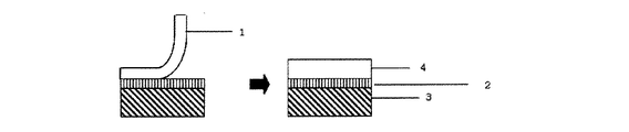
上述の(A)成分、(B)成分及び各種添加剤を、通常、加熱下にてそれぞれ所定の割合で均質に混練し、樹脂組成物を調製する。次いで、該樹脂組成物を用いて、押出し成形法、キャスト法、Tダイ押出し成形法、インフレーション法、射出成形法等の各種成形法によって、直接、偏光子の上に本発明の光学フィルムを作製することができる(図1参照)。また、上記各種成形法によって、光学フィルムを作製しておき、その後接着剤層を介して偏光子に貼り合わせても良い。
本発明では、偏光子上に作製される光学フィルムが配向しないことが望まれるため、延伸のかからない押出し成形、Tダイ成形が望ましい。
[Method for producing optical film]
Hereinafter, the manufacturing method of the optical film of this invention is demonstrated.
The above component (A), component (B) and various additives are usually homogeneously kneaded at a predetermined ratio under heating to prepare a resin composition. Next, using the resin composition, the optical film of the present invention is directly formed on the polarizer by various molding methods such as an extrusion molding method, a casting method, a T-die extrusion molding method, an inflation method, and an injection molding method. (See FIG. 1). Further, an optical film may be prepared by the above-described various molding methods and then bonded to a polarizer via an adhesive layer.
In the present invention, since it is desired that the optical film produced on the polarizer is not oriented, extrusion molding and T-die molding that do not require stretching are desirable.
直接偏光子の上に光学フィルムを製造する方法を図1に示す。図1では、事前に、偏光子3の上に接着剤層2を塗布しておき、押出し法にて上述の(A)成分、(B)成分及び各種添加剤の溶融樹脂を製膜して溶融樹脂層1を得る(図1左図)。製膜した該溶融樹脂層1が固化して保護膜4となる。
A method for producing an optical film directly on a polarizer is shown in FIG. In FIG. 1, the
本発明の光学フィルムの厚さについては10〜200μmの範囲が好ましい。該厚さが10μm以上であると、偏光子の保護膜としての強度が十分に確保され、200μm以下であると十分な可撓性が得られ、また軽量であることからハンドリングが容易であり、かつコスト的にも有利である。以上の観点から、該光学フィルムの厚さは30〜150μmがより好ましい。 About the thickness of the optical film of this invention, the range of 10-200 micrometers is preferable. When the thickness is 10 μm or more, the strength as a protective film of the polarizer is sufficiently ensured, and when it is 200 μm or less, sufficient flexibility is obtained, and since it is lightweight, handling is easy. It is also advantageous in terms of cost. From the above viewpoint, the thickness of the optical film is more preferably 30 to 150 μm.
このようにして、形成された光学フィルムには、各種の添加剤を添加して各種の機能、例えば、高硬度で耐擦傷性を有する、いわゆるハードコート機能、防曇コート機能、防汚コート機能、防眩コート機能、反射防止コート機能、紫外線遮蔽コート機能、赤外線遮蔽コート機能などを付与することもできる。 The optical film thus formed has various functions by adding various additives, for example, a so-called hard coat function, anti-fogging coat function, anti-fouling coating function having high hardness and scratch resistance. Further, an antiglare coating function, an antireflection coating function, an ultraviolet shielding coating function, an infrared shielding coating function, and the like can be provided.
本発明の光学フィルムは、画像表示装置等の各種装置の形成などに好ましく用いることができる。画像表示装置は、一般に、液晶セル、光学フィルム、及び必要に応じての照明システム等の構成部品を適宜に組立てて駆動回路を組込むことなどにより形成されるが、本発明においては上記光学フィルムを用いる点を除いて、画像表示装置の構成には特に限定はない。例えば、液晶セルの片側又は両側に偏光板又は光学フィルムを配置した画像表示装置や、照明システムとしてバックライト又は反射板を用いたものなどの適宜な画像表示装置が例示される。また、液晶セルについても、例えばTN型やSTN型、π型などの任意なタイプのものを用いうる。尚、画像表示装置を構成するに際しては、例えば拡散板、アンチグレア層、反射防止膜、保護板、プリズムアレイ、レンズアレイシート、光拡散板、バックライトなどの適宜な部品を適宜な位置に1層又は2層以上配置することができる。 The optical film of the present invention can be preferably used for forming various devices such as an image display device. In general, an image display device is formed by appropriately assembling components such as a liquid crystal cell, an optical film, and an illumination system as necessary, and incorporating a drive circuit. There is no particular limitation on the configuration of the image display device except that it is used. For example, an appropriate image display device such as an image display device in which a polarizing plate or an optical film is arranged on one side or both sides of a liquid crystal cell, or a device using a backlight or a reflector as an illumination system is exemplified. As the liquid crystal cell, any type such as a TN type, an STN type, or a π type can be used. In constructing the image display device, for example, a single layer of appropriate parts such as a diffusion plate, an antiglare layer, an antireflection film, a protective plate, a prism array, a lens array sheet, a light diffusion plate, and a backlight are provided at appropriate positions. Alternatively, two or more layers can be arranged.
[偏光板]
本発明に係る偏光板は、偏光子の片面又は両面に、上記本発明の光学フィルムを貼合したものである。ここで、該光学フィルムは偏光子と接着されて、保護膜としての機能を果たす。本発明の光学フィルムは面内位相差が10nm以下であり、上記各材料の最適化等により、面内位相差を6nm以下とすることができる。従って、本発明の光学フィルムを偏光子の保護膜として使用した場合には、保護膜の光学補償の影響が少ないという利点がある。
また、本発明の光学フィルムは光弾性定数が5×10-12/Pa以下であって、優れた光学特性を有するものである。なお、光弾性定数とは、応力に対する位相差の変化率をいい、光弾性定数が、特に10×10-12/Paより大きいとLCDにおいて、額縁状の光漏れが生じ、表示不良が発生することが知られている。これは、ガラス基板上に接着されている各種フィルムが、温度などの環境条件の変化から変形し、そこで発生した応力によって位相差が生じたことが原因とされている。本発明の光学フィルムは、光弾性定数が5×10-12/Pa以下であるので、偏光子の保護フィルムとして使用した際に、偏光板としての機能を高いレベルで維持することができる。
[Polarizer]
The polarizing plate according to the present invention is obtained by bonding the optical film of the present invention to one side or both sides of a polarizer. Here, the optical film is bonded to a polarizer and functions as a protective film. The optical film of the present invention has an in-plane retardation of 10 nm or less, and the in-plane retardation can be set to 6 nm or less by optimizing the above materials. Therefore, when the optical film of the present invention is used as a protective film for a polarizer, there is an advantage that the influence of optical compensation of the protective film is small.
The optical film of the present invention has a photoelastic constant of 5 × 10 −12 / Pa or less and has excellent optical characteristics. The photoelastic constant refers to the rate of change of the phase difference with respect to the stress. If the photoelastic constant is particularly larger than 10 × 10 −12 / Pa, a frame-like light leakage occurs in the LCD, resulting in a display defect. It is known. This is because various films adhered on the glass substrate are deformed due to changes in environmental conditions such as temperature, and a phase difference is caused by the stress generated there. Since the optical film of the present invention has a photoelastic constant of 5 × 10 −12 / Pa or less, the function as a polarizing plate can be maintained at a high level when used as a protective film for a polarizer.
本発明の偏光板で用いる偏光子としては、特定の振動方向をもつ光のみを透過する機能を有する偏光子であれば如何なるものでもよく、例えばポリビニルアルコール系フィルム等を延伸し、ヨウ素や二色性染料などで染色したポリビニルアルコール系偏光子;ポリビニルアルコールの脱水処理物やポリ塩化ビニルの脱塩酸処理物等のポリエン系偏光子;コレステリック液晶を用いた反射型偏光子;薄膜結晶フィルム系偏光子等が挙げられ、その中でもポリビニルアルコール系偏光子が好ましく用いられる。
ポリビニルアルコール系偏光子としては、例えばポリビニルアルコール系フィルム、部分ホルマール化ポリビニルアルコール系フィルム、エチレン・酢酸ビニル共重合体系部分ケン化フィルム等の親水性高分子フィルムに、ヨウ素や二色性染料等の二色性物質を吸着させて一軸延伸したものが挙げられる。これらのなかでもポリビニルアルコール系フィルムとヨウ素などの二色性物質からなる偏光子が好適に用いられる。これら偏光子の厚さは特に制限されず、一般的に、1〜100μm程度である。
As the polarizer used in the polarizing plate of the present invention, any polarizer may be used as long as it has a function of transmitting only light having a specific vibration direction. For example, a polyvinyl alcohol film is stretched, and iodine or two-color Polyvinyl alcohol polarizers dyed with reactive dyes; polyene polarizers such as dehydrated polyvinyl alcohol and dehydrochlorinated polyvinyl chloride; reflective polarizers using cholesteric liquid crystals; thin film crystal film polarizers Among them, polyvinyl alcohol polarizers are preferably used.
Examples of the polyvinyl alcohol polarizer include hydrophilic polymer films such as polyvinyl alcohol films, partially formalized polyvinyl alcohol films, ethylene / vinyl acetate copolymer partially saponified films, iodine and dichroic dyes, etc. A dichroic substance is adsorbed and uniaxially stretched. Among these, a polarizer composed of a polyvinyl alcohol film and a dichroic substance such as iodine is preferably used. The thickness of these polarizers is not particularly limited, and is generally about 1 to 100 μm.
偏光子を構成する樹脂として好適に用いられるPVA系樹脂は、ポリ酢酸ビニル系樹脂をケン化することにより得られる。ポリ酢酸ビニル系樹脂としては、酢酸ビニルの単独重合体であるポリ酢酸ビニルのほか、酢酸ビニル及びこれと共重合可能な他のモノマーの共重合などが例示される。酢酸ビニルに共重合される他のモノマーとしては、例えば、不飽和カルボン酸類、オレフィン類、ビニルエーテル類、不飽和スルホン酸類などが挙げられる。
PVA系樹脂のケン化度は、通常85〜100モル%、好ましくは98〜100モル%の範囲である。このPVA系樹脂は、さらに変性されていてもよく、例えば、アルデヒド類で変性されたポリビニルホルマールやポリビニルアセタールなども使用し得る。PVA系樹脂の重合度は、通常1,000〜10,000、好ましくは1,500〜10,000の範囲である。
A PVA resin suitably used as a resin constituting the polarizer can be obtained by saponifying a polyvinyl acetate resin. Examples of the polyvinyl acetate resin include not only polyvinyl acetate which is a homopolymer of vinyl acetate, but also copolymerization of vinyl acetate and other monomers copolymerizable therewith. Examples of other monomers copolymerized with vinyl acetate include unsaturated carboxylic acids, olefins, vinyl ethers, and unsaturated sulfonic acids.
The degree of saponification of the PVA-based resin is usually 85 to 100 mol%, preferably 98 to 100 mol%. This PVA-based resin may be further modified. For example, polyvinyl formal or polyvinyl acetal modified with aldehydes may be used. The degree of polymerization of the PVA resin is usually in the range of 1,000 to 10,000, preferably 1,500 to 10,000.
偏光板は、例えば、上述のようなPVA系樹脂フィルムを一軸延伸する工程、PVA系樹脂フィルムを二色性色素で染色して、その二色性色素を吸着させる工程、二色性色素が吸着されたPVA系樹脂フィルムをホウ酸水溶液で処理する工程、ホウ酸水溶液による処理後に水洗する工程、及びこれらの工程が施されて二色性色素が吸着配向された一軸延伸PVA系樹脂フィルムに保護膜を貼合する工程を経て、製造される。 The polarizing plate is, for example, a step of uniaxially stretching a PVA resin film as described above, a step of dyeing a PVA resin film with a dichroic dye, and adsorbing the dichroic dye, and a dichroic dye adsorbing A process of treating the prepared PVA resin film with an aqueous boric acid solution, a process of washing with water after the treatment with an aqueous boric acid solution, and a uniaxially stretched PVA resin film on which dichroic dyes are adsorbed and oriented by applying these steps Manufactured through a process of laminating films.
一軸延伸は、二色性色素による染色の前に行ってもよいし、二色性色素による染色と同時に行ってもよいし、また、二色性色素による染色の後に行ってもよい。一軸延伸を二色性色素による染色後に行う場合には、この一軸延伸は、ホウ酸処理の前に行ってもよいし、ホウ酸処理中に行ってもよい。また、これらの複数の段階で一軸延伸を行うことも可能である。一軸延伸するには、周速の異なるロール間で一軸に延伸してもよいし、熱ロールを用いて一軸に延伸してもよい。また、大気中で延伸を行う乾式延伸であってもよいし、溶剤により膨潤した状態で延伸を行う湿式延伸であってもよい。延伸倍率は、通常4〜8倍程度である。 Uniaxial stretching may be performed before dyeing with a dichroic dye, may be performed simultaneously with dyeing with a dichroic dye, or may be performed after dyeing with a dichroic dye. When uniaxial stretching is performed after dyeing with a dichroic dye, this uniaxial stretching may be performed before boric acid treatment or during boric acid treatment. Moreover, it is also possible to perform uniaxial stretching in these several steps. For uniaxial stretching, rolls having different peripheral speeds may be uniaxially stretched or uniaxially stretched using a hot roll. Moreover, the dry-type extending | stretching which extends | stretches in air | atmosphere may be sufficient, and the wet extending | stretching which extends | stretches in the state swollen with the solvent may be sufficient. The draw ratio is usually about 4 to 8 times.
PVA系樹脂フィルムを二色性色素で染色するには、例えば、PVA系樹脂フィルムを、二色性色素を含有する水溶液に浸漬すればよい。二色性色素として、具体的にはヨウ素又は二色性染料が用いられる。
二色性色素としてヨウ素を用いる場合は通常、ヨウ素及びヨウ化カリウムを含有する水溶液に、PVA系樹脂フィルムを浸漬して染色する方法が採用される。この水溶液におけるヨウ素の含有量は通常、水100質量部あたり0.01〜0.5質量部程度であり、ヨウ化カリウムの含有量は通常、水100質量部あたり0.5〜10質量部程度である。この水溶液の温度は、通常20〜40℃程度であり、また、この水溶液への浸漬時間は、通常30〜300秒程度である。
In order to dye the PVA resin film with the dichroic dye, for example, the PVA resin film may be immersed in an aqueous solution containing the dichroic dye. Specifically, iodine or a dichroic dye is used as the dichroic dye.
When iodine is used as the dichroic dye, a method of immersing and dyeing a PVA resin film in an aqueous solution containing iodine and potassium iodide is usually employed. The content of iodine in this aqueous solution is usually about 0.01 to 0.5 parts by mass per 100 parts by mass of water, and the content of potassium iodide is usually about 0.5 to 10 parts by mass per 100 parts by mass of water. It is. The temperature of this aqueous solution is usually about 20 to 40 ° C., and the immersion time in this aqueous solution is usually about 30 to 300 seconds.
一方、二色性色素として二色性染料を用いる場合は通常、水溶性二色性染料を含む水溶液に、PVA系樹脂フィルムを浸漬して染色する方法が採用される。この水溶液における二色性染料の含有量は通常、水100質量部あたり1×10⁻³〜1×10⁻²質量部程度である。この水溶液は、硫酸ナトリウムなどの無機塩を含有していてもよい。この水溶液の温度は、通常20〜80℃程度であり、また、この水溶液への浸漬時間は、通常30〜300秒程度である。
二色性色素による染色後のホウ酸処理は、染色されたPVA系樹脂フィルムをホウ酸水溶液に浸漬することにより行われる。ホウ酸水溶液におけるホウ酸の含有量は通常、水100質量部あたり2〜15質量部程度、好ましくは5〜12質量部程度である。
二色性色素としてヨウ素を用いる場合には、このホウ酸水溶液はヨウ化カリウムを含有するのが好ましい。ホウ酸水溶液におけるヨウ化カリウムの含有量は通常、水100質量部あたり2〜20質量部程度、好ましくは5〜15質量部である。ホウ酸水溶液への浸漬時間は、通常100〜1,200秒程度、好ましくは150〜600秒程度、さらに好ましくは200〜400秒程度である。ホウ酸水溶液の温度は、通常50℃以上であり、好ましくは50〜85℃である。
On the other hand, when a dichroic dye is used as the dichroic dye, a method of immersing and dyeing a PVA resin film in an aqueous solution containing a water-soluble dichroic dye is usually employed. The content of the dichroic dye in this aqueous solution is usually about 1 × 10 −3 to 1 × 10 −2 parts by mass per 100 parts by mass of water. This aqueous solution may contain an inorganic salt such as sodium sulfate. The temperature of this aqueous solution is usually about 20 to 80 ° C., and the immersion time in this aqueous solution is usually about 30 to 300 seconds.
The boric acid treatment after dyeing with a dichroic dye is performed by immersing the dyed PVA resin film in an aqueous boric acid solution. The boric acid content in the boric acid aqueous solution is usually about 2 to 15 parts by mass, preferably about 5 to 12 parts by mass per 100 parts by mass of water.
When iodine is used as the dichroic dye, the aqueous boric acid solution preferably contains potassium iodide. The content of potassium iodide in the boric acid aqueous solution is usually about 2 to 20 parts by mass, preferably 5 to 15 parts by mass per 100 parts by mass of water. The immersion time in the boric acid aqueous solution is usually about 100 to 1,200 seconds, preferably about 150 to 600 seconds, and more preferably about 200 to 400 seconds. The temperature of the boric acid aqueous solution is usually 50 ° C. or higher, preferably 50 to 85 ° C.
ホウ酸処理後のPVA系樹脂フィルムは、通常、水洗処理される。水洗処理は、例えば、ホウ酸処理されたPVA系樹脂フィルムを水に浸漬することにより行われる。水洗後は乾燥処理が施されて、偏光子が得られる。水洗処理における水の温度は、通常5〜40℃程度であり、浸漬時間は、通常2〜120秒程度である。その後に行われる乾燥処理は通常、熱風乾燥機や遠赤外線ヒーターを用いて行われる。乾燥温度は、通常40〜100℃である。乾燥処理における処理時間は、通常120〜600秒程度である。
こうして、ヨウ素又は二色性染料が吸着配向されたPVA系樹脂フィルムからなる偏光子が得られる。
The PVA resin film after boric acid treatment is usually washed with water. The water washing treatment is performed, for example, by immersing a boric acid-treated PVA resin film in water. After washing with water, a drying process is performed to obtain a polarizer. The temperature of water in the water washing treatment is usually about 5 to 40 ° C., and the immersion time is usually about 2 to 120 seconds. The drying process performed thereafter is usually performed using a hot air dryer or a far infrared heater. The drying temperature is usually 40 to 100 ° C. The processing time in the drying process is usually about 120 to 600 seconds.
In this way, a polarizer comprising a PVA resin film in which iodine or dichroic dye is adsorbed and oriented is obtained.
光学フィルムと偏光子との貼合の方法としては、上述のように、接着剤層を介して行われる。
接着剤層を形成する接着剤としては、PVA系接着剤、エポキシ系接着剤、アクリル系接着剤、不飽和カルボン酸またはその無水物をグラフトさせたポリオレフィンもしくは該グラフトさせたポリオレフィンをブレンドしたポリオレフィン系接着剤などが挙げられる。その他、透明性を有する接着剤、例えば、ポリビニルエーテル系、ゴム系等の接着剤を使用することができる。
As a method of pasting an optical film and a polarizer, as mentioned above, it is performed through an adhesive layer.
As an adhesive for forming the adhesive layer, a PVA adhesive, an epoxy adhesive, an acrylic adhesive, a polyolefin grafted with an unsaturated carboxylic acid or an anhydride thereof, or a polyolefin system blended with the grafted polyolefin Examples include adhesives. In addition, an adhesive having transparency, for example, an adhesive such as polyvinyl ether or rubber can be used.
PVA系接着剤は、PVA系樹脂と架橋剤を含有するものであり、PVA系樹脂としては、例えばポリ酢酸ビニルをケン化して得られたPVA及びその誘導体、酢酸ビニルと共重合性を有するモノマーとの共重合体のケン化物、PVAをアセタール化、ウレタン化、エーテル化、グラフト化又はリン酸エステル化等した変性PVAなどが挙げられる。これらPVA系樹脂は一種を単独でまたは二種以上を併用することができる。酢酸ビニルと共重合性を有するモノマーとしては、(無水)マレイン酸、フマル酸、クロトン酸、イタコン酸、(メタ)アクリル酸等の不飽和カルボン酸及びそのエステル類、エチレンやプロピレン等のα−オレフィン、(メタ)アリルスルホン酸(ソーダ)、スルホン酸ソーダ(モノアルキルマレート)、ジスルホン酸ソーダアルキルマレート、N−メチロールアクリルアミド、アクリルアミドアルキルスルホン酸アルカリ塩、N−ビニルピロリドン、N−ビニルピロリドン誘導体等が挙げられる。
PVA系樹脂の重合度等は特に限定されないが、接着性などが良好になることから、平均重合度100〜3,000程度、好ましくは500〜3,000、平均ケン化度85〜100モル%程度、好ましくは90〜100モル%程度のものを用いることが好ましい。
The PVA-based adhesive contains a PVA-based resin and a crosslinking agent. Examples of the PVA-based resin include PVA obtained by saponifying polyvinyl acetate and its derivatives, and a monomer copolymerizable with vinyl acetate. And a modified PVA obtained by subjecting PVA to acetalization, urethanization, etherification, grafting, or phosphoric esterification. These PVA resins can be used singly or in combination of two or more. Examples of monomers copolymerizable with vinyl acetate include (anhydrous) maleic acid, fumaric acid, crotonic acid, itaconic acid, (meth) acrylic acid and other unsaturated carboxylic acids and esters thereof, and α- such as ethylene and propylene. Olefin, (meth) allylsulfonic acid (soda), sulfonic acid soda (monoalkylmalate), disulfonic acid soda alkylmalate, N-methylolacrylamide, acrylamide alkylsulfonic acid alkali salt, N-vinylpyrrolidone, N-vinylpyrrolidone Derivatives and the like.
The degree of polymerization of the PVA-based resin is not particularly limited, but since the adhesiveness and the like are improved, the average degree of polymerization is about 100 to 3,000, preferably 500 to 3,000, and the average degree of saponification 85 to 100 mol%. It is preferable to use a material having a degree of about 90 to 100 mol%.
エポキシ系接着剤としては、水素化エポキシ樹脂、脂環式エポキシ樹脂、脂肪族エポキシ樹脂などがある。エポキシ樹脂には、さらにオキタセン類やポリオール類など、カチオン重合を促進する化合物を含有してもよい。 Examples of the epoxy adhesive include a hydrogenated epoxy resin, an alicyclic epoxy resin, and an aliphatic epoxy resin. The epoxy resin may further contain a compound that promotes cationic polymerization, such as okitacenes and polyols.
アクリル系接着剤としては、アクリル酸ブチル、アクリル酸エチル、アクリル酸メチル、アクリル酸2−エチルヘキシル等のアクリル酸エステルと、アクリル酸、マレイン酸、イタコン酸、メタクリル酸、クロトン酸等のα−モノオレフィンカルボン酸との共重合物(アクリルニトリル、酢酸ビニル、スチロールの如きビニルモノマーを添加したものも含む)を主体とするものが、偏光子の偏光特性を阻害することがないので特に好ましい。 Acrylic adhesives include acrylic esters such as butyl acrylate, ethyl acrylate, methyl acrylate and 2-ethylhexyl acrylate, and α-mono such as acrylic acid, maleic acid, itaconic acid, methacrylic acid and crotonic acid. Those mainly composed of a copolymer with an olefin carboxylic acid (including those added with vinyl monomers such as acrylonitrile, vinyl acetate and styrene) are particularly preferred because they do not impair the polarizing properties of the polarizer.
また、不飽和カルボン酸またはその無水物をグラフトさせたポリオレフィンもしくは該グラフトさせたポリオレフィンをブレンドしたポリオレフィンを接着剤として使用することもできる。グラフトに用いられるポリオレフィンとしては、たとえば低密度ポリエチレン、高密度ポリエチレン、ポリプロピレン、ポリ−1−ブテン、ポリ−4−メチル−1−ペンテン、エチレンープロピレン共重合体、エチレン−1−ブテン共重合体、プロピレン−1−ブテン共重合体、これらの混合物などである。ポリオレフィンのグラフトに用いる不飽和カルボン酸またはその無水物としては、アクリル酸、メタクリル酸、マレイン酸、無水マレイン酸、シトラコン酸、無水シトラコン酸、イタコン酸、無水イタコン酸などを挙げることができる。こうして得た変性ポリオレフィンはそのまま用いてもよいが、他のポリオレフィンに配合して用いることもできる。 Further, a polyolefin grafted with an unsaturated carboxylic acid or an anhydride thereof or a polyolefin blended with the grafted polyolefin can also be used as an adhesive. Examples of polyolefins used for grafting include low density polyethylene, high density polyethylene, polypropylene, poly-1-butene, poly-4-methyl-1-pentene, ethylene-propylene copolymer, and ethylene-1-butene copolymer. , Propylene-1-butene copolymer, and mixtures thereof. Examples of the unsaturated carboxylic acid or anhydride thereof used for polyolefin grafting include acrylic acid, methacrylic acid, maleic acid, maleic anhydride, citraconic acid, citraconic anhydride, itaconic acid, and itaconic anhydride. The modified polyolefin thus obtained may be used as it is, but may also be used by blending with other polyolefins.
上記接着剤層は、光学フィルム、偏光子のいずれかの側または両側に、接着剤を塗布することにより形成する。接着剤層の厚みは、好ましくは0.01〜10μm、さらに好ましくは0.03〜5μmである。 The adhesive layer is formed by applying an adhesive on either or both sides of the optical film and the polarizer. The thickness of the adhesive layer is preferably 0.01 to 10 μm, more preferably 0.03 to 5 μm.
また、上記光学フィルムを偏光子と接着させるに際し、光学フィルムの偏光子と接する面に接着性向上のために易接着処理を施すことができる。易接着処理としては、コロナ処理、プラズマ処理、低圧UV処理、ケン化処理等の表面処理やアンカー層を形成する方法が挙げられ、これらを併用することもできる。これらの中でも、コロナ処理、アンカー層を形成する方法、およびこれらを併用する方法が好ましい。 Moreover, when bonding the said optical film with a polarizer, an easily bonding process can be performed for the adhesive improvement to the surface which contact | connects the polarizer of an optical film. Examples of the easy adhesion treatment include surface treatment such as corona treatment, plasma treatment, low-pressure UV treatment, and saponification treatment, and a method of forming an anchor layer, and these can be used in combination. Among these, a corona treatment, a method of forming an anchor layer, and a method of using these in combination are preferable.
次いで、上記のようにして易接着処理を行った面に接着剤層を形成し、該接着剤層を介して、本発明の光学フィルムと偏光子とを貼り合せる。この貼り合わせは、ロールラミネーター等により行うことができる。なお、加熱乾燥温度、乾燥時間は接着剤の種類に応じて適宜決定される。 Next, an adhesive layer is formed on the surface subjected to the easy adhesion treatment as described above, and the optical film of the present invention and the polarizer are bonded through the adhesive layer. This bonding can be performed by a roll laminator or the like. The heating drying temperature and drying time are appropriately determined according to the type of adhesive.
[画像表示装置]
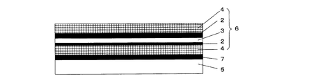
本発明の偏光板は、例えば液晶セルなどに貼り合わせて使用される。図2に、本発明の偏光板を有する液晶セルの構成例を示す。図2において、5は液晶セルを示す。この液晶セル5は、例えば、薄膜トランジスタ型に代表されるアクティブマトリクス駆動型等や、ツイストネマチック型、スーパーツイストネマチック型に代表される単純マトリクス駆動型などのものが例示される。この液晶セル5の上に、粘着剤層(図示せず)を介して、位相差板7が積層され、この上に、粘着剤層(図示せず)を介して、本発明の偏光板6が積層されている。偏光板6は、中心に偏光子3を有し、その両側の表面に、接着剤層2を介して、本発明の光学フィルムで構成される保護膜4が積層されている。本発明の偏光板6と位相差板7、位相差板7と液晶セル5の積層に際しては、予め偏光板6、位相差板7及び液晶セル5に粘着剤層を設けておくこともできる。
[Image display device]
The polarizing plate of the present invention is used by being bonded to, for example, a liquid crystal cell. In FIG. 2, the structural example of the liquid crystal cell which has the polarizing plate of this invention is shown. In FIG. 2, 5 indicates a liquid crystal cell. Examples of the liquid crystal cell 5 include an active matrix drive type typified by a thin film transistor type and a simple matrix drive type typified by a twist nematic type and a super twist nematic type. A
本発明の偏光板と液晶セルを積層する粘着剤としては特に限定されず、例えばアクリル系重合体、シリコーン系ポリマー、ポリエステル、ポリウレタン、ポリアミド、ポリエーテル、フッ素系やゴム系などのポリマーをベースポリマーとするものを適宜に選択して用いることができる。
該粘着剤には、光学的透明性、適度な濡れ性、凝集性、接着性などの粘着特性、耐候性、耐熱性などに優れることが求められる。さらに吸湿による発泡現象や剥がれ現象の防止、熱膨張差等による光学特性の低下や液晶セルの反り防止、ひいては高品質で耐久性に優れる画像表示装置の形成性などの点より、吸湿率が低くて耐熱性に優れる粘着剤層が求められる。現在、これらの要求性状を考慮して、アクリル系粘着剤が最も好ましい。
The pressure-sensitive adhesive for laminating the polarizing plate and the liquid crystal cell of the present invention is not particularly limited. For example, an acrylic polymer, silicone polymer, polyester, polyurethane, polyamide, polyether, fluorine-based or rubber-based polymer is a base polymer. Can be appropriately selected and used.
The pressure-sensitive adhesive is required to be excellent in optical transparency, suitable wettability, cohesiveness, adhesive properties such as adhesion, weather resistance, heat resistance and the like. Furthermore, the moisture absorption rate is low in terms of preventing foaming and peeling due to moisture absorption, reducing optical characteristics due to thermal expansion differences, preventing warping of liquid crystal cells, and, in turn, forming a high-quality and durable image display device. Therefore, a pressure-sensitive adhesive layer having excellent heat resistance is required. At present, acrylic pressure-sensitive adhesives are most preferable in consideration of these required properties.
粘着剤には、例えば天然物や合成物の樹脂類、特に、粘着性付与樹脂や、ガラス繊維、ガラスビーズ、金属粉、その他の無機粉末等からなる充填剤や顔料、着色剤、酸化防止剤などの添加剤を含有していてもよい。また微粒子を含有して光拡散性を示す粘着剤層であってもよい。 Examples of the pressure-sensitive adhesive include natural and synthetic resins, in particular, tackifier resins, fillers and pigments made of glass fibers, glass beads, metal powders, other inorganic powders, colorants, antioxidants, and the like. Etc. may be contained. Moreover, the adhesive layer which contains microparticles | fine-particles and shows light diffusibility may be sufficient.
本発明の偏光板への上記粘着剤の塗工は、特に限定されず、適宜な方法で行うことができる。例えば、トルエンや酢酸エチル等の適宜な溶剤の単独物又は混合物からなる溶媒に、ベースポリマー又はその組成物を溶解又は分散させた10〜40質量%程度の粘着剤溶液を調製し、それを流延方式や塗工方式等の適宜な展開方式で本発明の偏光板上に直接塗工する方法、或いはこの方法に準じ離型性ベースフィルム上に粘着剤層を形成してそれを本発明の偏光板に移着する方法などが挙げられる。
塗工方法は、グラビアコート、バーコート、ロールコート、リバースロールコート、コンマコート等、各種方法が可能であるが、グラビアコートが最も一般的である。
The application of the pressure-sensitive adhesive to the polarizing plate of the present invention is not particularly limited, and can be performed by an appropriate method. For example, a pressure-sensitive adhesive solution of about 10 to 40% by mass in which a base polymer or a composition thereof is dissolved or dispersed in a solvent composed of an appropriate solvent alone or a mixture such as toluene or ethyl acetate is prepared, and the resulting solution is allowed to flow. A method of coating directly on the polarizing plate of the present invention by an appropriate development method such as a rolling method or a coating method, or forming an adhesive layer on a releasable base film according to this method and applying it to the present invention. The method of transferring to a polarizing plate is mentioned.
As the coating method, various methods such as gravure coating, bar coating, roll coating, reverse roll coating, comma coating and the like are possible, but gravure coating is the most common.
粘着剤層は、異なる組成又は種類等のものの重畳層として本発明の偏光板の片面又は両面に設けることもできる。また、両面に設ける場合、本発明の偏光板の表裏において、粘着剤が同一組成である必要はなく、また同一の厚さである必要もない。異なる組成、異なる厚さの粘着剤層とすることもできる。
また、粘着剤層の厚さは、使用目的や接着力などに応じて適宜に決定でき、一般には1μm〜500μmであり、5μm〜200μmが好ましく、特に10μm〜100μmが好ましい。
The pressure-sensitive adhesive layer can also be provided on one or both sides of the polarizing plate of the present invention as a superimposed layer of different compositions or types. Moreover, when providing in both surfaces, the adhesive does not need to be the same composition in the front and back of the polarizing plate of this invention, and it is not necessary to be the same thickness. It can also be set as the adhesive layer of a different composition and different thickness.
The thickness of the pressure-sensitive adhesive layer can be appropriately determined according to the purpose of use and adhesive force, and is generally 1 μm to 500 μm, preferably 5 μm to 200 μm, particularly preferably 10 μm to 100 μm.
粘着剤層の露出面に対しては、実用に供するまでの間、その汚染防止等を目的に離型性フィルムが仮着されてカバーされることが好ましい。これにより、通例の取扱状態で粘着剤層に接触することを防止できる。離型性フィルムとしては、例えばプラスチックフィルム、ゴムシート、紙、布、不織布、ネット、発泡シートや金属箔、それらのラミネート体等の適宜なフィルムを、必要に応じシリコーン系や長鎖アルキル系、フッ素系や硫化モリブデン等の適宜な剥離剤でコート処理したものなどの、従来公知なものを用いることができる。 The exposed surface of the pressure-sensitive adhesive layer is preferably temporarily covered with a release film for the purpose of preventing the contamination until it is put to practical use. Thereby, it can prevent contacting an adhesive layer in the usual handling state. As the releasable film, for example, an appropriate film such as a plastic film, rubber sheet, paper, cloth, non-woven fabric, net, foamed sheet or metal foil, and a laminate thereof, if necessary, silicone-based or long-chain alkyl-based, Conventionally known materials such as those coated with an appropriate release agent such as fluorine-based or molybdenum sulfide can be used.
なお、本発明において、上記偏光子、保護膜層、粘着剤層などの各層には、例えばサリチル酸エステル系化合物やベンゾフェノール系化合物、ベンゾトリアゾール系化合物やシアノアクリレート系化合物、ニッケル錯塩系化合物等の紫外線吸収剤で処理する方式などにより紫外線吸収能を付与してもよい。 In the present invention, the polarizer, the protective film layer, the pressure-sensitive adhesive layer, and the like include, for example, salicylic acid ester compounds, benzophenol compounds, benzotriazole compounds, cyanoacrylate compounds, nickel complex compounds, and the like. Ultraviolet absorbing ability may be imparted by a method of treating with an ultraviolet absorber.
また、本発明の光学フィルムを偏光子の保護膜として、偏光子の少なくとも一方の面に貼り合わせる本発明の偏光板には、必要に応じて偏光子の他方の面に、本発明の光学フィルムを積層することもできるし、その他の樹脂からなるフィルムを積層することもできる。その他の樹脂からなるフィルムとしては、例えばTACフィルム、ポリエーテルサルフォンフィルム、ポリアリレートフィルム、ポリエチレンテレフタレートフィルム、ポリナフタレンテレフタレートフィルム、ポリカーボネートフィルム、環状ポリオレフィンフィルム、マレイミド系樹脂フィルム、フッ素系樹脂フィルム等が挙げられる。上記その他の樹脂からなるフィルムは特定の位相差を持つ位相差フィルムであっても良い。 In addition, the polarizing plate of the present invention, which is bonded to at least one surface of the polarizer as the protective film of the polarizer of the present invention, is provided on the other surface of the polarizer as necessary. Can be laminated, and films made of other resins can be laminated. Examples of other resin films include TAC films, polyethersulfone films, polyarylate films, polyethylene terephthalate films, polynaphthalene terephthalate films, polycarbonate films, cyclic polyolefin films, maleimide resin films, fluorine resin films, and the like. Can be mentioned. The film made of the other resin may be a retardation film having a specific retardation.
本発明の偏光板は、表面性、耐傷付き性を向上させる為に、少なくとも一層以上のハードコート層を有する積層体とすることが好ましい。該ハードコート層としては、例えばシリコーン系樹脂、アクリル系樹脂、アクリルシリコーン系樹脂、紫外線硬化型樹脂、ウレタン系ハードコート剤等よりなるハードコート層が挙げられ、その中でも透明性、耐傷付き性、耐薬品性の点から、紫外線硬化型樹脂よりなるハードコート層が好ましい。これらのハードコート層は、一種類以上で用いることができる。
紫外線硬化型樹脂としては、例えば紫外線硬化型アクリルウレタン、紫外線硬化型エポキシアクリレート、紫外線硬化型(ポリ)エステルアクリレート、紫外線硬化型オキセタン等から選ばれる一種類以上の紫外線硬化樹脂が挙げられる。
ハードコート層の厚みは、0.1〜100μmが好ましく、特に好ましくは1〜50μm、さらに好ましくは2〜20μmである。また、ハードコート層の間にプライマー処理をすることもできる。
The polarizing plate of the present invention is preferably a laminate having at least one hard coat layer in order to improve surface properties and scratch resistance. Examples of the hard coat layer include a hard coat layer made of, for example, a silicone resin, an acrylic resin, an acrylic silicone resin, an ultraviolet curable resin, a urethane hard coat agent, etc. Among them, transparency, scratch resistance, From the viewpoint of chemical resistance, a hard coat layer made of an ultraviolet curable resin is preferable. One or more of these hard coat layers can be used.
Examples of the ultraviolet curable resin include one or more ultraviolet curable resins selected from ultraviolet curable acrylic urethane, ultraviolet curable epoxy acrylate, ultraviolet curable (poly) ester acrylate, ultraviolet curable oxetane, and the like.
As for the thickness of a hard-coat layer, 0.1-100 micrometers is preferable, Especially preferably, it is 1-50 micrometers, More preferably, it is 2-20 micrometers. Further, a primer treatment can be performed between the hard coat layers.
[有機EL表示装置への適用]
本発明の偏光板は、有機EL表示装置にも好適に使用し得る。
一般に、有機EL表示装置は、透明基板上に透明電極と有機発光層と金属電極とを順に積層して発光体(有機エレクトロルミネセンス発光体)を形成している。ここで、有機発光層は、種々の有機薄膜の積層体であり、例えばトリフェニルアミン誘導体等からなる正孔注入層と、アントラセン等の蛍光性の有機固体からなる発光層との積層体や、あるいはこのような発光層とペリレン誘導体等からなる電子注入層の積層体や、これらの正孔注入層、発光層、および電子注入層の積層体等、種々の組み合わせをもった構成が知られている。
[Application to organic EL display devices]
The polarizing plate of the present invention can be suitably used for an organic EL display device.
Generally, in an organic EL display device, a transparent electrode, an organic light emitting layer, and a metal electrode are sequentially laminated on a transparent substrate to form a light emitter (organic electroluminescent light emitter). Here, the organic light emitting layer is a laminate of various organic thin films, for example, a laminate of a hole injection layer made of a triphenylamine derivative and the like and a light emitting layer made of a fluorescent organic solid such as anthracene, Or, a structure having various combinations such as a stacked body of an electron injection layer composed of such a light emitting layer and a perylene derivative, a stacked body of these hole injection layer, light emitting layer, and electron injection layer is known. Yes.
有機EL表示装置は、透明電極と金属電極とに電圧を印加することによって、有機発光層に正孔と電子とが注入され、これら正孔と電子との再結合によって生じるエネルギーが蛍光物資を励起し、励起された蛍光物質が基底状態に戻るときに光を放射する、という原理で発光する。途中の再結合というメカニズムは、一般のダイオードと同様であり、このことからも予想できるように、電流と発光強度は印加電圧に対して整流性を伴う強い非線形性を示す。
有機EL表示装置においては、有機発光層での発光を取り出すために、少なくとも一方の電極が透明でなくてはならず、通常酸化インジウムスズ(ITO)などの透明導電体で形成した透明電極を陽極として用いている。一方、電子注入を容易にして発光効率を上げるには、陰極に仕事関数の小さな物質を用いることが重要で、通常Mg−Ag、Al−Liなどの金属電極を用いている。
In organic EL display devices, holes and electrons are injected into the organic light-emitting layer by applying a voltage to the transparent electrode and the metal electrode, and the energy generated by recombination of these holes and electrons excites the phosphor material. Then, light is emitted on the principle that the excited fluorescent material emits light when returning to the ground state. The mechanism of recombination in the middle is the same as that of a general diode, and as can be predicted from this, the current and the emission intensity show strong nonlinearity with rectification with respect to the applied voltage.
In an organic EL display device, in order to extract light emitted from the organic light emitting layer, at least one of the electrodes must be transparent, and a transparent electrode usually formed of a transparent conductor such as indium tin oxide (ITO) is used as an anode. It is used as On the other hand, in order to facilitate electron injection and increase luminous efficiency, it is important to use a material having a small work function for the cathode, and usually metal electrodes such as Mg—Ag and Al—Li are used.
このような構成の有機EL表示装置において、有機発光層は、厚さ10nm程度ときわめて薄い膜で形成されている。このため、有機発光層も透明電極と同様、光をほぼ完全に透過する。その結果、非発光時に透明基板の表面から入射し、透明電極と有機発光層とを透過して金属電極で反射した光が、再び透明基板の表面側へと出るため、外部から視認したとき、有機EL表示装置の表示面が鏡面のように見える。 In the organic EL display device having such a configuration, the organic light emitting layer is formed of a very thin film having a thickness of about 10 nm. For this reason, the organic light emitting layer transmits light almost completely like the transparent electrode. As a result, light that is incident from the surface of the transparent substrate at the time of non-light emission, passes through the transparent electrode and the organic light emitting layer, and is reflected by the metal electrode is again emitted to the surface side of the transparent substrate. The display surface of the organic EL display device looks like a mirror surface.
電圧の印加によって発光する有機発光層の表面側に透明電極を備えるとともに、有機発光層の裏面側に金属電極を備えてなる有機エレクトロルミネセンス発光体を含む有機EL表示装置において、透明電極の表面側に本発明の偏光板を設け且つ該透明電極と偏光板との間に複屈折層(位相差板)を設けることができる。 In an organic EL display device comprising an organic electroluminescent light emitting device comprising a transparent electrode on the surface side of an organic light emitting layer that emits light upon application of a voltage and a metal electrode on the back side of the organic light emitting layer, the surface of the transparent electrode The polarizing plate of the present invention can be provided on the side, and a birefringent layer (retardation plate) can be provided between the transparent electrode and the polarizing plate.
本発明の偏光板は、外部から入射して金属電極で反射してきた光を偏光する作用を有するため、その偏光作用によって金属電極の鏡面を外部から視認させないという効果がある。特に、複屈折層をλ/4板で構成し、かつ偏光板と該複屈折層との偏光方向のなす角をπ/4に調整すれば、金属電極の鏡面を完全に遮蔽することができる。
すなわち、この有機EL表示装置に入射する外部光は、偏光板により直線偏光成分のみが透過する。この直線偏光は、一般には複屈折層によって楕円偏光となるが、複屈折層がλ/4板でしかも偏光板との偏光方向のなす角がπ/4のときには円偏光となる。この円偏光は、透明基板、透明電極、有機薄膜を透過し、金属電極で反射して、再び有機薄膜、透明電極、透明基板を透過して、複屈折層で再び直線偏光となる。そして、この直線偏光は、偏光板の偏光方向と直交しているので、偏光板を透過できない。その結果、金属電極の鏡面を完全に遮蔽することができる。
Since the polarizing plate of the present invention has a function of polarizing light incident from the outside and reflected by the metal electrode, there is an effect that the mirror surface of the metal electrode is not visually recognized from the outside by the polarization action. In particular, if the birefringent layer is composed of a λ / 4 plate and the angle between the polarizing direction of the polarizing plate and the birefringent layer is adjusted to π / 4, the mirror surface of the metal electrode can be completely shielded. .
That is, only the linearly polarized light component of the external light incident on the organic EL display device is transmitted by the polarizing plate. This linearly polarized light generally becomes elliptically polarized light by the birefringent layer, but becomes circularly polarized light when the birefringent layer is a λ / 4 plate and the angle formed by the polarization direction with the polarizing plate is π / 4. This circularly polarized light is transmitted through the transparent substrate, the transparent electrode, and the organic thin film, reflected by the metal electrode, again transmitted through the organic thin film, the transparent electrode, and the transparent substrate, and becomes linearly polarized light again by the birefringent layer. And since this linearly polarized light is orthogonal to the polarization direction of a polarizing plate, it cannot permeate | transmit a polarizing plate. As a result, the mirror surface of the metal electrode can be completely shielded.
[タッチパネルへの適用]
本発明の光学フィルムは、タッチパネルの偏光板にも好適に使用し得る。一般に、タッチパネルは、操作者が表示画面の上部に設けられた透明な面をペン、または指でタッチすることで、装置、システムの操作を行うものである。画面上を直接タッチすることは、カーソルを方向キーで押して位置を確定することに比べれば、より直接的であり、また直感的でもあることから、近年、非常に多用されるようになってきた。また、近年、携帯電話、およびPDA(Personal Digital Assistants;個人用の携帯情報端末)等の携帯端末市場の成長は著しく、太陽光のもとでの視認性、および薄型軽量が強く要求されるようになった。タッチパネルには種々の方式があり、その得失により使い分けられている。タッチパネルには、抵抗膜方式、光学式、静電容量結合方式(アナログ容量結合方式とも呼ばれる)、赤外線方式、超音波式、および電磁誘導式等の方式がある。ここでは、抵抗膜方式のタッチパネルの例で説明する。
[Applied to touch panel]
The optical film of this invention can be used conveniently also for the polarizing plate of a touchscreen. In general, a touch panel is a device in which an operator operates a device or a system by touching a transparent surface provided at the top of a display screen with a pen or a finger. Touching the screen directly has become more and more popular in recent years because it is more direct and intuitive than pressing the cursor with a direction key to confirm the position. . In recent years, the growth of mobile terminals such as mobile phones and PDAs (Personal Digital Assistants) has been remarkable, and there is a strong demand for visibility under the sunlight and thin and light weight. Became. There are various types of touch panels, and they are properly used depending on their advantages and disadvantages. The touch panel includes a resistive film method, an optical method, a capacitive coupling method (also called an analog capacitive coupling method), an infrared method, an ultrasonic method, and an electromagnetic induction method. Here, an example of a resistive film type touch panel will be described.
抵抗膜方式のタッチパネルには、ガラス/ガラスタイプとガラス/フィルムタイプがある。ガラス/ガラスタイプは透明導電層付ガラス基板と透明導電層付ガラス基板が空間を介して保持されたものであり、これがディスプレイ表面に装着される。また、ガラス/フィルムタイプは、車載用あるいは携帯用のタッチパネルにおいて、より軽量化・薄型化したものが望まれるため、上部の透明導電層付ガラス基板を光学フィルムで置き換えたタイプのタッチパネルである。
ガラス/ガラスタイプのタッチパネルを図3、ガラス/フィルムタイプのタッチパネルを図4に示す。
直線偏光板、あるいは偏光板にλ/4板を組み合わせて積層した円偏光板をタッチパネルの最表面に使用すれば、タッチパネルとして十分な強度を得ることができ、かつ、反射防止の効果により視認性が向上する。タッチパネルの偏光板は、図3において8、図4において16である。これらタッチパネルの偏光板に本発明の光学フィルムが好適に使用できる。
本発明の光学フィルムと偏光子からなる偏光板とλ/4板を、λ/4板の面内の遅相軸と偏光板の偏光軸との角度が実質的に45°になるように積層すると円偏光板が得られる。実質的に45度とは、40〜50度であることを意味する。λ/4板の面内の遅相軸と偏光膜の偏光軸との角度は、41〜49度であることが好ましく、42〜48度であることがより好ましく、43〜47度であることがさらに好ましく、44〜46度であることが最も好ましい。
本発明の光学フィルムは偏光板の保護膜上・下・下外(ITOを設ける軽量化用フィルム)のいずれにも使用できる。またタッチパネルの反射防止には、直線偏光タイプと円偏光タイプがあるが(直線偏光は円偏光に比べて反射率が高い)、本発明の光学フィルムは円偏光板にも直線偏光タイプの偏光板にも使用できる。
本発明の光学フィルムを使用した円偏光板、又は直線偏光板は、透過型・反射型どちらのタッチパネルにも使用できる。
Resistive touch panels include a glass / glass type and a glass / film type. In the glass / glass type, a glass substrate with a transparent conductive layer and a glass substrate with a transparent conductive layer are held via a space, and this is mounted on the display surface. The glass / film type is a type of touch panel in which an upper glass substrate with a transparent conductive layer is replaced with an optical film because a lighter / thinner one is desired in an in-vehicle or portable touch panel.
A glass / glass type touch panel is shown in FIG. 3, and a glass / film type touch panel is shown in FIG.
If a linearly polarizing plate or a circularly polarizing plate made by combining a polarizing plate with a λ / 4 plate is used on the outermost surface of the touch panel, sufficient strength can be obtained as a touch panel, and visibility can be improved due to the antireflection effect. Will improve. The polarizing plates of the touch panel are 8 in FIG. 3 and 16 in FIG. The optical film of this invention can be used conveniently for the polarizing plate of these touch panels.
A polarizing plate and a λ / 4 plate comprising the optical film of the present invention and a polarizer are laminated so that the angle between the slow axis in the plane of the λ / 4 plate and the polarizing axis of the polarizing plate is substantially 45 °. A circularly polarizing plate is then obtained. Substantially 45 degrees means 40 to 50 degrees. The angle between the slow axis in the plane of the λ / 4 plate and the polarization axis of the polarizing film is preferably 41 to 49 degrees, more preferably 42 to 48 degrees, and 43 to 47 degrees. Is more preferable, and it is most preferable that it is 44 to 46 degrees.
The optical film of the present invention can be used for any of the upper, lower and lower outer layers (lightweight reduction film provided with ITO) of the polarizing plate. There are two types of anti-reflection for touch panels: linearly polarized light type and circularly polarized light type (linearly polarized light has a higher reflectance than circularly polarized light). Can also be used.
The circularly polarizing plate or linearly polarizing plate using the optical film of the present invention can be used for both transmissive and reflective touch panels.
次に、本発明を実施例により、さらに詳細に説明するが、本発明は、この例によってなんら限定されるものではない。
(評価方法)
1.可撓性の評価
実施例及び比較例で得られた光学フィルムから10cm角の試験片を切り出し、半分に二つ折りした。折り曲げた際にフィルムが割れなかった場合を「○」、圧をかけて割れた場合を「△」、圧をかけずに割れた場合を「×」とした。
2.面内位相差の評価
面内位相差を、波長589.3nm、入射角0度で位相差測定機(王子計測機器(株)製「KOBRA−WR」)を用いて測定した。
3.耐熱性(ブロッキング)の評価
実施例及び比較例で得られた光学フィルムを巻き取り、80℃ドライ条件下及び90℃ドライ条件下で1,000時間保管し、その後のフィルムの外観を観察した。ブロッキングが発生せず、融着の傾向が全く無い場合を「◎」、ブロッキングは発生しないが、融着の傾向がある場合を「○」、ブロッキングが起きた場合を「×」とした。
4.光弾性定数の評価
実施例及び比較例で得られた光学フィルムに関し、株式会社ユニオプト製「ABR−EX」を用いて測定した。
EXAMPLES Next, although an Example demonstrates this invention further in detail, this invention is not limited at all by this example.
(Evaluation methods)
1. Evaluation of flexibility A 10 cm square test piece was cut out from the optical films obtained in Examples and Comparative Examples, and was folded in half. The case where the film did not break when bent was designated as “◯”, the case where it was cracked under pressure as “Δ”, and the case where it was cracked without pressure as “x”.
2. Evaluation of in-plane retardation The in-plane retardation was measured using a phase difference measuring device (“KOBRA-WR” manufactured by Oji Scientific Instruments) at a wavelength of 589.3 nm and an incident angle of 0 degree.
3. Evaluation of heat resistance (blocking) The optical films obtained in Examples and Comparative Examples were wound up and stored for 1,000 hours under 80 ° C. dry conditions and 90 ° C. dry conditions, and the subsequent appearance of the films was observed. The case where blocking did not occur and there was no fusion tendency was indicated as “◎”, the case where blocking did not occur but there was a tendency for fusion was indicated as “◯”, and the case where blocking occurred was indicated as “x”.
4). Evaluation of Photoelastic Constant The optical films obtained in Examples and Comparative Examples were measured using “ABR-EX” manufactured by UNIOPT Co., Ltd.
実施例1
(A)環状オレフィン共重合体(三井化学(株)製、商品名「アペルAPL6011T」(第1表中では「APL6011T」と表記);環状ポリオレフィン20〜30モル%、Tg105℃)90質量%と(B)エチレン−アクリル酸共重合体(日本ポリエチレン(株)製、商品名「レクスパールEAA/A3100」(第1表中では「EAA」と表記))10質量%を混練し、加工温度185℃でコンパウンド化した。上記コンパウンド化にて作製したペレットを加工温度260℃・引取りロール温度50℃で100μmの厚さでTダイ押出し成形し、光学フィルムを得た。当該光学フィルムについて、上記評価方法にて評価した。結果を第1表に示す。
Example 1
(A) 90% by mass of cyclic olefin copolymer (manufactured by Mitsui Chemicals, Inc., trade name “Apel APL6011T” (indicated as “APL6011T” in Table 1); cyclic polyolefin 20-30 mol%, Tg 105 ° C.) (B) 10% by mass of an ethylene-acrylic acid copolymer (manufactured by Nippon Polyethylene Co., Ltd., trade name “Lexpearl EAA / A3100” (indicated as “EAA” in Table 1)), a processing temperature of 185 Compounded at ℃. The pellets produced by the compounding were extruded at a processing temperature of 260 ° C. and a take-up roll temperature of 50 ° C. at a thickness of 100 μm to obtain an optical film. The optical film was evaluated by the above evaluation method. The results are shown in Table 1.
実施例2
(A)成分の含有量を95質量%、(B)成分の含有量を5質量%としたこと以外は実施例1と同様にして光学フィルムを得た。実施例1と同様に評価した結果を第1表に示す。
Example 2
An optical film was obtained in the same manner as in Example 1 except that the content of the component (A) was 95% by mass and the content of the component (B) was 5% by mass. The results of evaluation in the same manner as in Example 1 are shown in Table 1.
実施例3
(A)成分の含有量を80質量%、(B)成分の含有量を20質量%としたこと以外は実施例1と同様にして光学フィルムを得た。実施例1と同様に評価した結果を第1表に示す。
Example 3
An optical film was obtained in the same manner as in Example 1 except that the content of the component (A) was 80% by mass and the content of the component (B) was 20% by mass. The results of evaluation in the same manner as in Example 1 are shown in Table 1.
実施例4
(A)成分として他の環状オレフィン共重合体(三井化学製、商品名「アペルAPL5014DP(第1表中では「APL5014DP」と表記)」;環状ポリオレフィン35〜45モル%、Tg145℃)を使用したこと以外は実施例1と同様にして光学フィルムを得た。実施例1と同様に評価した結果を第1表に示す。
Example 4
As the component (A), another cyclic olefin copolymer (manufactured by Mitsui Chemicals, trade name “Apel APL5014DP (shown as“ APL5014DP ”in Table 1)”; cyclic polyolefin 35 to 45 mol%, Tg 145 ° C.) was used. An optical film was obtained in the same manner as in Example 1 except that. The results of evaluation in the same manner as in Example 1 are shown in Table 1.
実施例5
(B)エチレン−アクリル酸共重合体に代えて、エチレン−無水マレイン酸−アクリル酸エステル3元共重合体(日本ポリエチレン(株)製、商品名「レクスパールET/ET220X」(第1表中では「ET」と表記))としたこと以外は実施例1と同様にして光学フィルムを得た。実施例1と同様に評価した結果を第1表に示す。
Example 5
(B) In place of ethylene-acrylic acid copolymer, ethylene-maleic anhydride-acrylic acid ester terpolymer (manufactured by Nippon Polyethylene Co., Ltd., trade name “Lexpearl ET / ET220X” (in Table 1) Then, an optical film was obtained in the same manner as in Example 1 except that “ET” was used. The results of evaluation in the same manner as in Example 1 are shown in Table 1.
実施例6
(A)成分として他の環状オレフィン共重合体(三井化学製、商品名「アペルAPL8008T」(第1表中では「APL8008T」と表記);環状ポリオレフィン15〜25モル%、Tg70℃)を使用したこと以外は実施例1と同様にして光学フィルムを得た。実施例1と同様に評価した結果を第1表に示す。
Example 6
As the component (A), another cyclic olefin copolymer (manufactured by Mitsui Chemicals, trade name “Apel APL8008T” (indicated as “APL8008T” in Table 1);
比較例1
(A)成分の含有量を99質量%、(B)成分の含有量を1質量%としたこと以外は実施例1と同様にして光学フィルムを得た。実施例1と同様に評価した結果を第1表に示す。
Comparative Example 1
An optical film was obtained in the same manner as in Example 1 except that the content of the component (A) was 99% by mass and the content of the component (B) was 1% by mass. The results of evaluation in the same manner as in Example 1 are shown in Table 1.
比較例2
(A)成分の含有量を65質量%、(B)成分の含有量を35質量%としたこと以外は実施例1と同様にして光学フィルムを得た。実施例1と同様に評価した結果を第1表に示す。
Comparative Example 2
An optical film was obtained in the same manner as in Example 1 except that the content of the component (A) was 65% by mass and the content of the component (B) was 35% by mass. The results of evaluation in the same manner as in Example 1 are shown in Table 1.
比較例3
(A)成分のみを用いたこと以外は実施例1と同様にして光学フィルムを得た。実施例1と同様に評価した結果を第1表に示す。
Comparative Example 3
An optical film was obtained in the same manner as in Example 1 except that only the component (A) was used. The results of evaluation in the same manner as in Example 1 are shown in Table 1.
本発明によれば、ヘーズが小さく透明性に優れ、複屈折の低い等の光学特性に優れ、良好な機械強度および耐熱性を有し、透湿性に優れる光学フィルムを提供することができる。また、耐熱性、耐湿熱性、耐冷熱サイクル等の各種耐久性に優れ、また偏光板の光学的機能に何ら影響を与えることなく、偏光板の偏光度を向上させることができ、しかも、柔軟でかつ弾性に富む光学フィルムを提供することができる。
また、本発明の光学フィルムは外部からの衝撃や変形に対し抵抗力を有するため、この光学フィルムを偏光子に貼り合わせて用いることで、液晶表示素子としての強度や信頼性を顕著に向上させた偏光板を提供することができる。
さらに、本発明の光学フィルムは、従来汎用されているTACフィルムと比較すると、TACフィルムが親水性であり、防湿性が殆んどないのに対し、本発明の光学フィルムは疎水性であるので、偏光板の耐久性を大幅に向上させることができる。従って、本発明の光学フィルムは、偏光板の少なくとも一面に積層されて液晶セル表面基板と接着される保護膜として好適に使用でき、さらには偏光板の他面側の保護膜に使用することもできる。
According to the present invention, it is possible to provide an optical film having excellent optical properties such as low haze, excellent transparency, low birefringence, excellent mechanical strength and heat resistance, and excellent moisture permeability. In addition, it has excellent durability such as heat resistance, moist heat resistance and cold heat cycle, and can improve the degree of polarization of the polarizing plate without affecting the optical function of the polarizing plate. In addition, an optical film rich in elasticity can be provided.
Further, since the optical film of the present invention has resistance to external impacts and deformations, the strength and reliability as a liquid crystal display element can be remarkably improved by using the optical film by being bonded to a polarizer. A polarizing plate can be provided.
Furthermore, the optical film of the present invention is more hydrophobic than the conventionally used TAC film, whereas the optical film of the present invention is hydrophobic, whereas the optical film of the present invention is hydrophobic. The durability of the polarizing plate can be greatly improved. Therefore, the optical film of the present invention can be suitably used as a protective film laminated on at least one surface of the polarizing plate and bonded to the liquid crystal cell surface substrate, and can also be used as a protective film on the other side of the polarizing plate. it can.
1.溶融樹脂層
2.接着剤層
3.偏光子
4.保護膜
5.液晶セル
6.偏光板
7.位相差板(複屈折板)
8.タッチパネルの偏光板
9.反射防止膜
10.λ/4板
11.偏光子の保護膜[上]
11’.偏光子の保護膜[下]
12.偏光子(PVA)
13.ガラス
14.ITO保護膜
15.偏光子の保護膜[下外]
16.タッチパネルの偏光板
1. 1.
8). 8. Polarizing plate of touch
11 '. Polarizer protective film [bottom]
12 Polarizer (PVA)
13.
16. Touch panel polarizing plate
Claims (7)
(式中、R1は置換基Qを有していてもよい炭素数1〜20の2価の炭化水素基、R2は水素原子又は炭素数1〜10の1価の炭化水素基、R3は炭素数2〜10の4価の炭化水素基、QはCOOR4(R4は水素原子又は炭素数1〜10の1価の炭化水素基、Qが複数ある場合はそれぞれが同一でも異なってもよい)で示されるカルボキシル基又はアルコキシカルボニル基、nは0〜20の整数、x及びyは0/100≦y/x≦95/5の関係を満たす実数である。) (A) From the resin composition containing the cyclic olefin copolymer 70-97 mass% represented by the following general formula (I), and (B) 3-30 mass% of the binary or ternary copolymer of an olefin. An optical film.
(In the formula, R 1 is a divalent hydrocarbon group having 1 to 20 carbon atoms which may have a substituent Q, R 2 is a hydrogen atom or a monovalent hydrocarbon group having 1 to 10 carbon atoms, R 3 is a tetravalent hydrocarbon group having 2 to 10 carbon atoms, Q is COOR 4 (R 4 is a hydrogen atom or a monovalent hydrocarbon group having 1 to 10 carbon atoms, and when there are a plurality of Q, each is the same or different. And n is an integer of 0 to 20, and x and y are real numbers satisfying the relationship of 0/100 ≦ y / x ≦ 95/5.)
(a)オレフィン
(b)α,β−不飽和カルボン酸、その無水物及びα,β−不飽和カルボン酸グリシジルエステルからなる群から選ばれる不飽和カルボン酸
(c)不飽和エステル The optical film according to claim 1, wherein the component (B) is a copolymer of at least two monomers selected from the group consisting of the following components (a), (b), and (c).
(A) an olefin (b) an α, β-unsaturated carboxylic acid, an anhydride thereof, and an unsaturated carboxylic acid (c) an unsaturated ester selected from the group consisting of an α, β-unsaturated carboxylic acid glycidyl ester
Priority Applications (1)
| Application Number | Priority Date | Filing Date | Title |
|---|---|---|---|
| JP2007072933A JP2008233533A (en) | 2007-03-20 | 2007-03-20 | Optical film, polarizing plate and image display device |
Applications Claiming Priority (1)
| Application Number | Priority Date | Filing Date | Title |
|---|---|---|---|
| JP2007072933A JP2008233533A (en) | 2007-03-20 | 2007-03-20 | Optical film, polarizing plate and image display device |
Publications (1)
| Publication Number | Publication Date |
|---|---|
| JP2008233533A true JP2008233533A (en) | 2008-10-02 |
Family
ID=39906384
Family Applications (1)
| Application Number | Title | Priority Date | Filing Date |
|---|---|---|---|
| JP2007072933A Withdrawn JP2008233533A (en) | 2007-03-20 | 2007-03-20 | Optical film, polarizing plate and image display device |
Country Status (1)
| Country | Link |
|---|---|
| JP (1) | JP2008233533A (en) |
Cited By (4)
| Publication number | Priority date | Publication date | Assignee | Title |
|---|---|---|---|---|
| JP2009132849A (en) * | 2007-12-03 | 2009-06-18 | Daicel Novafoam Ltd | Olefin resin composition |
| WO2010038751A1 (en) * | 2008-10-02 | 2010-04-08 | 大日本印刷株式会社 | Optical film for protecting polarizer, polarizing plate and image display device |
| CN102736134A (en) * | 2011-04-12 | 2012-10-17 | 惠和株式会社 | Optical film, optical diaphragm and liquid display module |
| WO2016159406A1 (en) * | 2015-03-31 | 2016-10-06 | 코오롱인더스트리 주식회사 | Coc-based optically isotropic film and method for manufacturing same |
-
2007
- 2007-03-20 JP JP2007072933A patent/JP2008233533A/en not_active Withdrawn
Cited By (5)
| Publication number | Priority date | Publication date | Assignee | Title |
|---|---|---|---|---|
| JP2009132849A (en) * | 2007-12-03 | 2009-06-18 | Daicel Novafoam Ltd | Olefin resin composition |
| WO2010038751A1 (en) * | 2008-10-02 | 2010-04-08 | 大日本印刷株式会社 | Optical film for protecting polarizer, polarizing plate and image display device |
| CN102736134A (en) * | 2011-04-12 | 2012-10-17 | 惠和株式会社 | Optical film, optical diaphragm and liquid display module |
| JP2012220854A (en) * | 2011-04-12 | 2012-11-12 | Keiwa Inc | Optical film, optical sheet, and liquid crystal display module |
| WO2016159406A1 (en) * | 2015-03-31 | 2016-10-06 | 코오롱인더스트리 주식회사 | Coc-based optically isotropic film and method for manufacturing same |
Similar Documents
| Publication | Publication Date | Title |
|---|---|---|
| JP5231157B2 (en) | Polarizing plate, manufacturing method thereof, optical film, and image display device | |
| JP5444601B2 (en) | Polarizing plate, image display device, and manufacturing method of polarizing plate | |
| JP5231181B2 (en) | Polarizing plate, manufacturing method thereof, optical film, and image display device | |
| CN101398501B (en) | Polarizing plate, method for producing same, optical film, and image display device | |
| TWI406041B (en) | A polarizing plate and an image display device with an adhesive optical compensation layer | |
| CN103443236B (en) | Light curable adhesive, polaroid and laminated optical component | |
| JP2010107969A (en) | Optical film for protecting polarizer, polarizing plate and image display device | |
| US20100062189A1 (en) | Optical film, polarizing plate and image display device | |
| JP5167083B2 (en) | Polarizing plate, manufacturing method thereof, optical film, and image display device | |
| JP2009122664A (en) | Polarizing plate, optical film and image display device | |
| CN101828135A (en) | Optical film, polarizing plate and image display device | |
| JP5360070B2 (en) | Optical film for protecting polarizer, polarizing plate, and image display device | |
| CN110709738B (en) | Polarizing plate with adhesive layer | |
| JP5444602B2 (en) | Polarizing plate, image display device, and manufacturing method of polarizing plate | |
| CN103597383B (en) | Use the polarizer and laminated optical component of light curable adhesive | |
| JP5487623B2 (en) | Method for producing optical film for protecting polarizer, polarizing plate, and display device | |
| JP2009139660A (en) | Polarizing plate, manufacturing method thereof, optical film, and image display device | |
| JP2008233533A (en) | Optical film, polarizing plate and image display device | |
| JP4985506B2 (en) | Optical film, polarizing plate and image display device | |
| JP2009139720A (en) | Polarizing plate, manufacturing method thereof, optical film, and image display device | |
| TWI411810B (en) | Anti-electrification optical film, anti-charged adhesive type optical film and image display device | |
| WO2008059983A1 (en) | Optical film, polarizing plate and image display device | |
| JP2009139723A (en) | Polarizing plate, manufacturing method thereof, optical film, and image display device | |
| JP2009103730A (en) | Optical film, polarizing plate and image display device | |
| JP2009216937A (en) | Optical film, polarizing plate, and image display |
Legal Events
| Date | Code | Title | Description |
|---|---|---|---|
| A300 | Withdrawal of application because of no request for examination |
Free format text: JAPANESE INTERMEDIATE CODE: A300 Effective date: 20100601 |