JP2008213463A - Inkjet recording device and its cleaning control method - Google Patents
Inkjet recording device and its cleaning control method Download PDFInfo
- Publication number
- JP2008213463A JP2008213463A JP2007309064A JP2007309064A JP2008213463A JP 2008213463 A JP2008213463 A JP 2008213463A JP 2007309064 A JP2007309064 A JP 2007309064A JP 2007309064 A JP2007309064 A JP 2007309064A JP 2008213463 A JP2008213463 A JP 2008213463A
- Authority
- JP
- Japan
- Prior art keywords
- suction
- ink
- cleaning
- recording head
- suction pump
- Prior art date
- Legal status (The legal status is an assumption and is not a legal conclusion. Google has not performed a legal analysis and makes no representation as to the accuracy of the status listed.)
- Granted
Links
Images


Landscapes
- Ink Jet (AREA)
Abstract
Description
本発明は、インクジェット記録装置およびそのクリーニング制御方法に関する。 The present invention relates to an ink jet recording apparatus and a cleaning control method thereof.
従来、複数のノズルが記録ヘッド面に配列され、これら複数のノズルから画像データに応じてインク滴を吐出するインクジェット記録ヘッドを、記録面に対して相対移動させて、画像形成、印字などを行うインクジェット記録装置が知られている。 Conventionally, a plurality of nozzles are arranged on a recording head surface, and an inkjet recording head that discharges ink droplets from the plurality of nozzles according to image data is moved relative to the recording surface to perform image formation, printing, and the like. Ink jet recording apparatuses are known.
このようなインクジェット記録ヘッドは、記録画素の大きさに対応した微小径のノズルが、記録ヘッド面に多数配列しているため、インク内の異物、ゴミや記録ヘッド面に対して外部から付着するゴミなどによってノズルが目詰まりしたとき、あるいは目詰まりを予防するために適宜の周期で、クリーニングを行う必要がある。そのため、インクジェット記録装置には、インクジェット記録ヘッドをクリーニングする機構が備えられている。 In such an ink jet recording head, since a large number of nozzles having a small diameter corresponding to the size of the recording pixel are arranged on the recording head surface, it adheres from the outside to foreign matter in the ink, dust, or the recording head surface. It is necessary to perform cleaning when the nozzle is clogged with dust or the like or at an appropriate cycle to prevent clogging. Therefore, the inkjet recording apparatus is provided with a mechanism for cleaning the inkjet recording head.
例えば、特許文献1には、このようなクリーニング機構として、記録ヘッドをキャップにより封止して、インクを吸引する吸引によるクリーニング機構と、記録ヘッド面をワイピングするワイピングによるクリーニング機構とが設けられている。そして、それぞれを用いて、インクを大量吸引してから、ワイピングを行い、さらに、インクを少量吸引してからワイピングすることを複数繰り返すことで、クリーニングを行うインクジェット式記録装置が記載されている。
For example, in
ここで、吸引によるクリーニングは、吸引ポンプによりキャップ内に負圧を形成してノズルからインクを吸引する吸引動作と、吸引ポンプを停止してキャップ内の負圧を緩和する負圧解除処理と、キャップに設けられた大気開放バルブを開弁してから吸引ポンプを再稼働してキャップ内に吸引されたインクのみを空吸引する動作を、この順に行うようになっている。
しかしながら、上記のような従来のインクジェット記録装置、およびインクジェット記録ヘッドのクリーニング制御方法には、以下のような問題があった。 However, the conventional ink jet recording apparatus and the ink jet recording head cleaning control method as described above have the following problems.
特許文献1に記載の技術では、負圧解除処理においてキャップ内の圧力測定を行わないため、吸引ポンプを所定時間停止させ、この間に負圧が十分緩和されたものとして、空吸引を行うことになる。そのため、例えば、インクの状態やノズルの目詰まりの状態によっては、必ずしも十分に負圧を緩和できない状態で、空吸引動作が行われてしまう場合がある。
In the technique described in
この場合、大気開放バルブを開弁すると、残存する負圧の影響で、空気が勢いよくキャップ内に流入する結果、ノズルからインクジェット記録ヘッド内に、吸引済みのゴミやワイプ液などの不純物を含むインクが逆流し、クリーニングの効果が減退してしまう。また、キャップ内ではこのような不純物を含むインクが飛散して記録ヘッドのノズル開口に付着したりする。これらのため、ノズルが目詰まりしたり、ノズル先端のメニスカスが破壊されたりして、印字不良を招くおそれがあるという問題がある。 In this case, when the air release valve is opened, air is vigorously flowing into the cap due to the influence of the remaining negative pressure. As a result, impurities such as sucked dust and wipe liquid are contained in the inkjet recording head from the nozzle. Ink flows backward, and the cleaning effect decreases. Also, ink containing such impurities scatters within the cap and adheres to the nozzle openings of the recording head. For these reasons, there is a problem that the nozzle may be clogged or the meniscus at the tip of the nozzle may be destroyed, leading to a printing failure.
負圧を十分に緩和するために、吸引ポンプを長時間停止させることも考えられるが、停
止時間が長くなると、クリーニング時間が延びてしまうという問題がある。インクジェット記録ヘッドのクリーニングは、印字等の性能を維持するためには頻繁に行う必要があり、さらに特許文献1に記載の装置では、1回のクリーニングにおいても上記の吸引動作を複数回行うため、吸引ポンプの停止時間が延ばされるとクリーニングに要する時間が大幅に延びてしまう。この場合、クリーニング実行時は印字等の記録動作を行うことができないので、記録動作の効率が低下してしまうという問題がある。
In order to sufficiently relieve the negative pressure, it is conceivable to stop the suction pump for a long time. However, if the stop time becomes longer, there is a problem that the cleaning time is extended. Ink jet recording head cleaning needs to be performed frequently in order to maintain performance such as printing. Further, in the apparatus described in
本発明は、上記のような問題に鑑みてなされたものであり、空吸引前に負圧が残っていても、良好かつ迅速なクリーニングを行うことができるインクジェット記録装置およびそのクリーニング制御方法を提供することを目的とする。 The present invention has been made in view of the above problems, and provides an ink jet recording apparatus capable of performing good and quick cleaning even when negative pressure remains before idle suction, and a cleaning control method thereof The purpose is to do.
上記の課題を解決するために、請求項1に記載の発明では、インクジェット記録装置において、複数のノズルが記録ヘッド面に配列され、前記複数のノズルから画像データに応じてインク滴を吐出するインクジェット記録ヘッドと、前記記録ヘッド面を前記インク滴の吐出方向側から覆って封止することで、前記記録ヘッド面上に吸引空間を形成するキャップ部と、前記吸引空間内に負圧を形成し、前記吸引空間内の内容物を吸引して、前記吸引空間外に排出する吸引ポンプと、前記キャップ部に接続され、前記吸引空間と大気とを選択的に連通させる大気開放弁と、少なくとも、前記吸引ポンプの吸引動作と前記大気開放弁の開閉動作とを制御するクリーニング制御部とを備え、該クリーニング制御部は、前記大気開放弁を閉じた状態として前記吸引ポンプを作動させる第1の吸引動作と、前記大気開放弁を閉じた状態において前記吸引ポンプを停止させて前記吸引空間内の負圧を緩和する圧力緩和動作と、前記大気開放弁を閉じた状態において前記吸引ポンプを作動させる第2の吸引動作と、前記大気開放弁を開いた状態として前記吸引ポンプを作動させる空吸引動作とを順次行うクリーニングモードを少なくとも備える構成とする。
In order to solve the above problems, in the invention according to
この発明によれば、クリーニング制御部が、第1の吸引動作、圧力緩和動作、第2の吸引動作、および空吸引動作を順次行うクリーニングモードを備えるので、第1の吸引動作において、大気開放弁を閉じた状態で、吸引ポンプによりキャップ部で封止された吸引空間内に負圧を形成し、記録ヘッド面のノズルからインクジェット記録ヘッド内のインクを吸引空間内に吸引し、吸引空間をインクで満たしつつ、吸引空間外に排出することができる。そして圧力緩和動作において、大気開放弁を閉じた状態で吸引ポンプを停止することで、ノズルからインクが徐々に流入して吸引空間内の圧力を緩和され、ノズル内の気泡を押し出すことができる。そして第2の吸引動作において、大気開放弁を閉じた状態で吸引ポンプを作動させ、ノズルから吸引空間に向かうインクの流れを形成することができる。そして空吸引動作において、大気開放弁を開いた状態で吸引ポンプを作動させることで、吸引空間内の内容物を吸引空間外に排出するが、このとき、第2の吸引動作で吸引ポンプが継続して作動させるため、負圧が残存していてもノズルへのインクの逆流が起こりにくく、さらに吸引空間内のインクも吸引空間外への流れが形成されているため、吸引空間内のインクも記録ヘッド側に飛散しにくくなる。この結果、圧力緩和動作の時間を短縮しても良好なクリーニング性能が得られる。 According to the present invention, the cleaning control unit includes the cleaning mode in which the first suction operation, the pressure relaxation operation, the second suction operation, and the idle suction operation are sequentially performed. In the closed state, a negative pressure is formed in the suction space sealed by the cap portion by the suction pump, the ink in the ink jet recording head is sucked into the suction space from the nozzle on the surface of the recording head, and the ink is sucked into the suction space. It can be discharged out of the suction space while filling. In the pressure relaxation operation, by stopping the suction pump with the atmosphere release valve closed, the ink gradually flows from the nozzle, the pressure in the suction space is relaxed, and the bubbles in the nozzle can be pushed out. In the second suction operation, the suction pump can be operated with the air release valve closed to form an ink flow from the nozzle toward the suction space. In the idle suction operation, the contents in the suction space are discharged out of the suction space by operating the suction pump with the air release valve opened. At this time, the suction pump continues in the second suction operation. Therefore, even if negative pressure remains, the ink does not easily flow back to the nozzle, and the ink in the suction space also flows out of the suction space. It becomes difficult to scatter to the recording head side. As a result, good cleaning performance can be obtained even if the time of the pressure relaxation operation is shortened.
請求項2に記載の発明では、請求項1に記載のインクジェット記録装置において、前記吸引ポンプは、吸引量可変に設けられ、前記クリーニング制御部は、前記吸引ポンプの前記第2の吸引動作および前記空吸引動作時の吸引量を、前記第1の吸引動作時の吸引量より小さい吸引量に設定する構成とする。 According to a second aspect of the present invention, in the inkjet recording apparatus according to the first aspect, the suction pump is provided with a variable amount of suction, and the cleaning control unit is configured to perform the second suction operation of the suction pump and the suction pump. The suction amount during the idle suction operation is set to a suction amount smaller than the suction amount during the first suction operation.
この発明によれば、第1の吸引動作では、より大きな吸引量で吸引を行うため、インクジェット記録ヘッド内の気泡、不純物などをインクとともに効率的に吸引できる。そして、第2の吸引動作、空吸引動作では、より小さな吸引量で吸引を行うため、安定した吸引
、空吸引動作を行うことができる。その結果、ノズルから吸引空間に向かう流れ、および吸引空間から吸引空間外に向かう流れの乱れが少なくなり、吸引空間に空気が流入する際のインク飛散などを低減できるとともに、ノズル先端に良好なメニスカスを形成することができる。
According to the present invention, in the first suction operation, suction is performed with a larger suction amount, so that bubbles, impurities, and the like in the inkjet recording head can be efficiently suctioned together with the ink. In the second suction operation and the idle suction operation, since suction is performed with a smaller suction amount, stable suction and idle suction operations can be performed. As a result, the turbulence of the flow from the nozzle to the suction space and the flow from the suction space to the outside of the suction space is reduced, ink scattering when air flows into the suction space can be reduced, and a good meniscus at the tip of the nozzle Can be formed.
請求項3に記載の発明では、複数のノズルが記録ヘッド面に配列され、前記複数のノズルから画像データに応じてインク滴を吐出するインクジェット記録ヘッドと、前記記録ヘッド面を前記インク滴の吐出方向側から覆って封止することで、前記記録ヘッド面上に吸引空間を形成するキャップ部と、前記吸引空間内に負圧を形成し、前記吸引空間内の内容物を吸引して、前記吸引空間外に排出する吸引ポンプと、前記キャップ部に接続され、前記吸引空間と大気とを選択的に連通させる大気開放弁とを備えるインクジェット記録装置のクリーニング制御方法であって、前記キャップ部によって前記記録ヘッド面を封止する封止工程と、前記大気開放弁を閉じて、前記吸引ポンプを作動させる第1の吸引工程と、
該第1の吸引工程で作動させた吸引ポンプを停止させて前記吸引空間内の負圧を緩和する圧力緩和工程と、該圧力緩和工程で停止させた吸引ポンプを作動させる第2の吸引工程と、該第2の吸引工程で作動させた吸引ポンプを作動させつつ、前記大気開放弁を開く空吸引工程とを順次行う方法とする。
According to a third aspect of the present invention, an ink jet recording head in which a plurality of nozzles are arranged on the recording head surface and ink droplets are ejected from the plurality of nozzles according to image data, and the ink droplets are ejected from the recording head surface. By covering and sealing from the direction side, a cap part that forms a suction space on the recording head surface, a negative pressure is formed in the suction space, and the contents in the suction space are sucked, A cleaning control method for an ink jet recording apparatus, comprising: a suction pump that discharges outside a suction space; and an atmosphere release valve that is connected to the cap portion and selectively communicates the suction space and the atmosphere. A sealing step of sealing the recording head surface, a first suction step of closing the atmosphere release valve and operating the suction pump;
A pressure relaxation step of easing the negative pressure in the suction space by stopping the suction pump operated in the first suction step; a second suction step of operating the suction pump stopped in the pressure relaxation step; A method of sequentially performing the empty suction step of opening the atmosphere release valve while operating the suction pump operated in the second suction step.
この発明によれば、請求項1に記載のインクジェット記録装置を用いてクリーニングを行うクリーニング制御方法となっているので、請求項1に記載の発明と同様の作用効果を備える。 According to the present invention, since the cleaning control method performs cleaning using the ink jet recording apparatus according to the first aspect, the same function and effect as the first aspect of the invention are provided.
請求項4に記載の発明では、請求項3に記載のインクジェット記録装置のクリーニング制御方法において、前記第2の吸引工程および前記から吸引工程で、前記吸引ポンプの吸引量を前記第1の吸引工程よりも小さい吸引量とする方法とする。 According to a fourth aspect of the present invention, in the cleaning control method for an ink jet recording apparatus according to the third aspect, the suction amount of the suction pump is changed to the first suction step in the second suction step and the first suction step. The suction amount is smaller than that.
この発明によれば、請求項2に記載のインクジェット記録装置を用いてクリーニングを行うクリーニング制御方法となっているので、請求項2に記載の発明と同様の作用効果を備える。 According to the present invention, since the cleaning control method performs cleaning using the ink jet recording apparatus according to the second aspect, the same effect as the invention according to the second aspect is provided.
請求項5に記載の発明では、請求項1に記載のインクジェット記録装置において、前記クリーニング制御部は、前記大気開放弁を閉じた状態として前記吸引ポンプを作動させる第3の吸引動作と、前記大気開放弁を閉じた状態において前記吸引ポンプを停止させて前記吸引空間内の負圧を緩和する圧力緩和動作と、前記吸引ポンプを停止した状態において、前記大気開放弁を開いた状態にさせる第2の圧力緩和動作と、前記大気開放弁を開いた状態として前記吸引ポンプを作動させる空吸引動作とを順次行った後に、前記ヘッド面上をワイパーによって清掃し、その後に前記クリーニングモードをおこなう制御をする。 According to a fifth aspect of the present invention, in the ink jet recording apparatus according to the first aspect, the cleaning control unit includes a third suction operation that operates the suction pump with the atmosphere release valve closed, and the atmosphere. A pressure relief operation for reducing the negative pressure in the suction space by stopping the suction pump in a state in which the release valve is closed; and a second state in which the atmosphere release valve is in an open state in a state in which the suction pump is stopped. The pressure relief operation and the empty suction operation for operating the suction pump with the atmosphere release valve opened are sequentially performed, and then the head surface is cleaned with a wiper and then the cleaning mode is performed. To do.
請求項5の発明によれば、請求項1の発明の効果に加え、ノズル内の気泡やゴミ、ヘッド面に付着したインク滴やゴミが取り除かれ、ヘッド面上の付着物によるインク吐出不良を無くすことができ、良好なクリーニングが行える。
According to the invention of
請求項6に記載の発明では、請求項1に記載のインクジェット記録装置において、前記クリーニング制御部は、前記第1の吸引動作によって少なくとも前記ヘッドの圧力室からノズルまでのインク経路に滞留しているインクを前記ヘッド外に吸引した後に前記第1の吸引動作に連続して前記圧力緩和動作を開始させる。 According to a sixth aspect of the present invention, in the ink jet recording apparatus according to the first aspect, the cleaning control unit stays in an ink path from at least the pressure chamber of the head to the nozzle by the first suction operation. After the ink is sucked out of the head, the pressure relaxation operation is started continuously with the first suction operation.
請求項6の発明によれば、第1の吸引動作によって、ワイパーの清掃によりヘッド内に押し込まれたものを出し切ることで、ノズル詰まりによる吐出不良を無くすことができ、良好なクリーニングが行える。 According to the sixth aspect of the present invention, it is possible to eliminate discharge defects due to nozzle clogging and perform good cleaning by completely removing what is pushed into the head by cleaning the wiper by the first suction operation.
請求項7に記載の発明では、請求項1または請求項6に記載のインクジェット記録装置において、前記クリーニング制御部は、前記圧力緩和動作によって前記吸引空間内の負圧がなくなる前に前記圧力緩和動作に連続して前記第2の吸引動作を開始させる。 According to a seventh aspect of the present invention, in the inkjet recording apparatus according to the first or sixth aspect, the cleaning control unit performs the pressure relaxation operation before the negative pressure in the suction space disappears due to the pressure relaxation operation. The second suction operation is started continuously.
請求項7の発明によれば、請求項1または請求項6に記載の発明の効果に加え、負圧が残る状態で第2の吸引動作をすることで、吸引の負荷を軽減できるとともに、インクの逆流を防止することができ、良好なクリーニングが行える。
According to the invention of
請求項8に記載の発明では、請求項1または請求項6または請求項7に記載のインクジェット記録装置において、前記クリーニング制御部は、前記第2の吸引動作によって発生させる負圧が前記第1の吸引動作によって発生さる負圧の最大値に達する前に前記第2の吸引動作に連続して前記空吸引動作をさせる。 According to an eighth aspect of the present invention, in the ink jet recording apparatus according to the first, sixth, or seventh aspect, the cleaning control unit is configured so that the negative pressure generated by the second suction operation is the first pressure. Before reaching the maximum value of the negative pressure generated by the suction operation, the idle suction operation is performed continuously with the second suction operation.
請求項8に記載の発明によれば、請求項1または請求項6または請求項7に記載の発明の効果に加え、第2の吸引動作によって逆流したインクを除去するのに十分な吸引をすることで、良好なクリーニングが行え、クリーニングモードによるインクの消費を削減できる。
According to the invention described in
請求項9に記載の発明では、請求項8に記載のインクジェット記録装置において、前記クリーニング制御部は、前記第2の吸引動作によって吸引されるインク量を、少なくとも前記ヘッドの圧力室からノズルまでのインク経路に滞留したインク量とする吸引をする制御をする。 According to a ninth aspect of the present invention, in the ink jet recording apparatus according to the eighth aspect, the cleaning control unit determines the amount of ink sucked by the second suction operation from at least the pressure chamber of the head to the nozzle. Control is performed so that the amount of ink staying in the ink path is sucked.
請求項9に記載の発明によれば、逆流したインクを除去するのに十分な吸引をすることで、良好なクリーニングが行え、クリーニングモードによるインクの消費も削減できる。 According to the ninth aspect of the present invention, the ink can be satisfactorily cleaned by sucking sufficient to remove the backflowed ink, and ink consumption in the cleaning mode can be reduced.
本発明のインクジェット記録装置およびそのクリーニング制御方法によれば、空吸引前にノズルおよび吸引空間内にインクの流れを形成しておくので、負圧が緩和しにくい場合でも、良好かつ迅速なクリーニングを行うことができるという効果を奏する。 According to the ink jet recording apparatus and the cleaning control method thereof of the present invention, since the ink flow is formed in the nozzle and the suction space before the idle suction, good and quick cleaning can be performed even when the negative pressure is difficult to relieve. There is an effect that it can be performed.
以下では、本発明の実施形態について添付図面を参照して説明する。 Embodiments of the present invention will be described below with reference to the accompanying drawings.
本発明の実施形態に係るインクジェット記録装置について説明する。 An ink jet recording apparatus according to an embodiment of the present invention will be described.
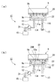
図1は、本発明の実施形態に係るインクジェット記録装置の概略構成を模式的に示す正面図である。図2は、本発明の実施形態に係るインクジェット記録装置のクリーニング部の概略構成を模式的に示す構成ブロック図である。 FIG. 1 is a front view schematically showing a schematic configuration of an ink jet recording apparatus according to an embodiment of the present invention. FIG. 2 is a configuration block diagram schematically showing a schematic configuration of the cleaning unit of the ink jet recording apparatus according to the embodiment of the present invention.
本実施形態のインクジェットプリンタ1(インクジェット記録装置)は、図1に示すように、シート状あるいは板状の記録媒体50を水平に配置して紙面奥行き方向に搬送し、インクジェット方式によって、記録媒体50の表面に画像データに応じた画像や文字などを記録、印字する(以下、まとめて、記録と称する)ものである。
As shown in FIG. 1, the ink jet printer 1 (ink jet recording apparatus) of the present embodiment arranges a sheet-like or plate-
インクジェットプリンタ1の概略構成は、記録媒体50を搬送する搬送部40と、記録
媒体50に記録する記録部41と、搬送部40の搬送方向横方向かつ記録部41の下方側に配置され記録部41に設けられた記録ヘッド9をクリーニングするクリーニングユニット10、およびクリーニングユニット10のクリーニング動作を制御するクリーニング制御部33(図2参照)からなる。また、特に図示しないが、インクジェットプリンタ1は、画像データの受信や記録動作の制御を含めた装置全体の制御を行う制御部を備えており、クリーニング制御部33はこの制御部の一部を構成している。
The schematic configuration of the
搬送部40は、図1の紙面奥行き方向に延ばされた略平板状のプラテン2上に、モータ5によって紙面に沿う水平軸回りに回転される複数のピンチローラ3を備え、これらピンチローラ3によって、ピンチローラ3の回転軸と平行な回転軸回りに回転自在に支持されたグリッドローラ4が、紙面奥行き方向に複数配列されている。これらグリッドローラ4は、プラテン2の上方において図示奥行き方向に延びる水平面に整列され、記録媒体50の搬送路を形成している。
The
記録部41は、搬送部40およびクリーニングユニット10の上方で、記録媒体50の搬送方向と直交する方向に延在されたキャリッジレール7と、キャリッジレール7に沿って移動可能に設けられた記録ヘッドユニット8と、記録ヘッドユニット8をキャリッジレール7上で位置制御および速度制御可能に往復移動させるモータ6と、記録ヘッドユニット8に記録用のインクを供給するインクカートリッジ17とからなる。
The
本実施形態では、インクカートリッジ17には、カラー記録を行うための複数色のインクが備えられ、複数のインクチューブ16を介して、色ごとに、記録ヘッドユニット8に供給できるようになっている。
In the present embodiment, the
記録ヘッドユニット8は、下面側に、インクの色や記録範囲などに応じて、複数の記録ヘッド9が設けられ、インクチューブ16から供給されるインクは、同色の記録を行う記録ヘッド9に分配して供給される。
The
また、記録ヘッドユニット8には、各記録ヘッド9の温度を適宜の温度範囲に保つための冷却ファン18が設けられている。
Further, the
記録ヘッド9は、図2に示すように、記録ヘッド本体9cの下面側において、搬送部40上の記録媒体50に平行に配置された記録ヘッド面9aが設けられ、記録ヘッド面9a上には、画像データに応じて一定のインク滴を下方に吐出するノズル9bが複数形成されてなる。
As shown in FIG. 2, the
なお、記録ヘッド本体9cの詳細は図示しないが、各ノズル9bにインクを供給するインク室や、例えば圧電素子などを用いた吐出機構が設けられている。
Although details of the recording head
また、図2では、ノズル9bは簡略化して4個のみを描いているが、吐出機構の構成や記録画素ピッチなどに応じて適宜の個数、配列ピッチで設けることができるものであり、例えば、256個などの多数個を配列しておくことができる。
In FIG. 2, only four
モータ6の位置制御、速度制御は、不図示の制御部の制御信号に応じて行われ、記録動作時には記録ヘッドユニット8を記録媒体50上で所定速度で往復移動させ、クリーニング動作時にはクリーニングユニット10内の所定クリーニング位置に移動できるようになっている。
The position control and speed control of the
クリーニングユニット10は、本実施形態では、記録ヘッド9内のインクをノズル9bから外部に吸引することで記録ヘッド9をクリーニングする吸引クリーニング部14Aと
、記録ヘッド面9aをワイピング処理することで記録ヘッド9をクリーニングするワイプ部14Bとからなり、搬送部40の側方かつ記録部41の下方における記録ヘッドユニット8の移動経路上に、搬送部40側からワイプ部14B、吸引クリーニング部14Aの順に配置されている。
In this embodiment, the
本実施形態は、これら吸引クリーニング部14A、ワイプ部14Bの上方位置が、所定のクリーニング位置となっている。
In the present embodiment, the upper positions of the
吸引クリーニング部14Aの概略構成は、図2に示すように、キャップ11(キャップ部)、キャップ駆動部30、吸引ポンプ12、ポンプ駆動部32、大気開放弁13、および大気開放弁駆動部31からなる。
As shown in FIG. 2, the schematic configuration of the suction cleaning unit 14 </ b> A includes a cap 11 (cap unit), a
これらのうち、少なくともキャップ11は記録ヘッド9ごとに設けられている。ただし、キャップ駆動部30、吸引ポンプ12、大気開放弁13、および大気開放弁駆動部31は、記録ヘッド9ごとに各動作を共通化できる場合には、複数のキャップ11に対して1台設ける構成としてもよい。以下では、説明の便宜上、1つの記録ヘッド9に対してそれぞれが1つずつ設けられている構成の例で説明する。
Among these, at least the
キャップ11は、上側に開口した函状とされ、記録ヘッド面9aに下方からかぶせることで、1つの記録ヘッド9のすべてのノズル9bを含む記録ヘッド面9aの領域を下方から囲んで封止する部材である。キャップ11の開口端部には、記録ヘッド面9aに弾性的に押圧されることで液密および気密シールを形成するための弾性体もしくは可撓体からなる封止部11bが全周にわたって設けられている。キャップ11の他の部分は、例えば、合成樹脂や金属などの適宜の剛性を有する部材からなる。そのため、封止時には、記録ヘッド面9aとキャップ11の内面との間に一定容積を有する吸引空間20が形成され、吸引空間20内が、ある程度負圧になっても、吸引空間20の形状が略維持されるようになっている。
The
キャップ11の底部の内面であるインク受け面11aは、記録ヘッド面9aと略平行な底面からなり、封止時には記録ヘッド面9aに対して所定距離をおいて対向される。そのため、ノズル9bからインクが吸引されて落下すると、インク受け面11a上に貯留できるようになっている。
The
インク受け面11aには、インク受け面11a上に貯留したインクを排出するための吸引管11Aと、吸引空間20をインク受け面11a側から大気に開放するための大気導入管11Bが設けられている。
The
キャップ駆動部30は、キャップ11の上下方向の位置を選択的に切り換えるための上下動を行うものであり、例えば、機械的、電磁的、流体的な適宜の昇降手段からなる。
The
そのため、キャップ駆動部30は、モータ6によってキャリッジレール7上を移動されて吸引クリーニング部14Aの上方に位置した状態の記録ヘッドユニット8に対して、キャップ11を上下方向に進退させ、キャップ11が記録ヘッド面9aを封止する状態と、封止を解除する状態とを切り換えることができるようになっている。
Therefore, the
吸引ポンプ12は、吸引空間20内の空気、インクなどの内容物を吸引して、吸引空間20外に排出するためのものであり、適宜構成の流体ポンプ、例えばロータリポンプなどを採用することができる。本実施形態では、ポンプ駆動部32により吸引量を可変できる構成とされている。例えば、ロータリポンプの場合には、ポンプ駆動部32によって、ポンプの回転数を可変して、単位時間当たりの流量を制御することで吸引量を変化させてい
る。本実施形態では、ポンプ駆動部32によって、吸引量が大きい高速モードと、吸引量が小さい低速モードとを選択できるようになっている。本実施形態では、一例として、低速モードの吸引量は高速モードの50%の吸引量に設定している。
The
ただし、吸引ポンプ12の吸引量は、必要に応じてさらに多段階に変化できるようにしてもよい。
However, the suction amount of the
吸引ポンプ12は、吸引口が吸引管11Aに接続され、排出口が排出管21に接続されている。排出管21の他端は、廃液ボトル15に接続されている。
The
大気開放弁13は、大気導入管11Bの大気に連通する開口を開閉するもので、大気開放弁駆動部31によって開状態と閉状態とが選択できるようになっている。
The
大気開放弁13の構成は、特に限定されないが、例えば、電磁弁などを採用することができる。
Although the structure of the
吸引クリーニング部14Aにおいて、キャップ駆動部30、大気開放弁駆動部31、ポンプ駆動部32は、クリーニング制御部33にそれぞれ電気的に接続され、クリーニング制御部33からの制御信号により、それぞれの動作が制御されるようになっている。
In the suction cleaning unit 14 </ b> A, the
ワイプ部14Bは、周知のワイピング処理を行うものであればどのような構成を有していてもよい。特に図示しないが、例えば、ワイプ部14Bの上方に移動された記録ヘッド9の記録ヘッド面9a上でワイプ液を含んだワイピングブレードを相対移動させることで、記録ヘッド面9aをワイピングする、といった構成を採用することができる。
The wipe
また、特に図示しないが、ワイプ部14Bもクリーニング制御部33によって動作が制御されるようになっている。
Although not specifically shown, the operation of the
次に、本実施形態のインクジェットプリンタ1におけるクリーニング動作について、吸引クリーニング部14Aでの動作を中心として説明する。
Next, the cleaning operation in the
図3は、本発明の実施形態に係るインクジェット記録装置のクリーニング動作のフローチャートである。図4は、本発明の実施形態に係るインクジェット記録装置のクリーニング動作のタイミングチャートである。図5(a)、(b)、(c)、(d)は、本発明の実施形態に係るインクジェット記録装置のクリーニング動作の各工程を示す模式的な工程説明図である。図6(a)、(b)は、図5に続く各工程を示す模式的な工程説明図である。図7(a)、(b)は、本発明の実施形態に係るクリーニング制御方法における第2の吸引工程および空吸引工程を示す模式的な工程説明図である。 FIG. 3 is a flowchart of the cleaning operation of the ink jet recording apparatus according to the embodiment of the present invention. FIG. 4 is a timing chart of the cleaning operation of the ink jet recording apparatus according to the embodiment of the present invention. FIGS. 5A, 5B, 5C, and 5D are schematic process explanatory views showing each process of the cleaning operation of the ink jet recording apparatus according to the embodiment of the present invention. FIGS. 6A and 6B are schematic process explanatory views showing each process following FIG. 7A and 7B are schematic process explanatory views showing a second suction process and an idle suction process in the cleaning control method according to the embodiment of the present invention.
なお、図4に示された時刻ti(i=1,…,18)は、特に断らない限りは、tj<tj+1(j=1,…,17)のように、添字の数字の大小によって時間的な前後関係を示すものとする。 Note that the time ti (i = 1,..., 18) shown in FIG. 4 is a time depending on the size of the subscript numbers, such as tj <tj + 1 (j = 1,..., 17) unless otherwise specified. The general context is shown.
以下に説明するのは、インクジェットプリンタ1が備える記録ヘッド9の1つのクリーニングモードであって、インクジェットプリンタ1は、必要に応じて、これ以外のクリーニングモードを備えていてもよい。
Described below is one cleaning mode of the
インクジェットプリンタ1における記録ヘッド9のクリーニング動作の一例は、図3に示すように、吸引クリーニング部14Aによるクリーニング(ステップS100)とワイプ部14Bによるワイピング処理(ステップS5)とを行い、さらに吸引クリーニング部
14Aによって仕上げのクリーニング(ステップS200)を行うものである。
As shown in FIG. 3, an example of the cleaning operation of the
ここで、ステップS100は、従来のクリーニングと同様な工程で行われる。 Here, step S100 is performed in the same process as the conventional cleaning.
そのため、記録ヘッドユニット8は、クリーニング動作の開始前に、制御部からの制御信号によって記録動作が停止されるとともに、モータ6が駆動されて、クリーニング位置である吸引クリーニング部14A上の定位置に移動される。このクリーニング位置では、各記録ヘッド9の下方に、対応する各キャップ11が対向している。
Therefore, the
クリーニング動作が開始されると、クリーニング制御部33によって、以下の各ステップが順次実行される。ステップS100では、ステップS1〜S4が順次実行される。
When the cleaning operation is started, the following steps are sequentially executed by the
クリーニング動作の初期状態(t<t1)では、図4に示すように、記録ヘッドユニット8が吸引クリーニング部14A上に位置し(ヘッド位置CL)、キャップ11は、記録ヘッド9の下方に位置し(キャップ開)、吸引ポンプ12は停止され(ポンプオフ)、大気開放弁13は閉じられている(大気開放弁閉)。
In the initial state of the cleaning operation (t <t1), as shown in FIG. 4, the
ステップS1では、時刻t1で、キャップ駆動部30によりキャップ11を上昇させ、図5(a)に示すように、キャップ11の封止部11bが記録ヘッド面9aを押圧する状態とする(キャップ閉)。これにより、記録ヘッド面9a上のノズル9bを囲う範囲がキャップ11で覆われ封止されて、吸引空間20が形成される。
In step S1, at time t1, the
次に、時刻t2で、ポンプ駆動部32により吸引ポンプ12を高速モードで作動させる(ポンプ高)。すると、吸引空間20内の空気が吸引管11A側に吸引される(図5(b)参照)。吸引空間20内の負圧が増大するにつれ、図5(c)に示すように、記録ヘッド9からインク22が吸引され、排出管21の排出量を上回るインク22は、吸引管11A、大気導入管11Bを満たし、インク受け面11a上に貯留される。そして、吸引空間20内にインク22が満たされる状態となる。
Next, at time t2, the
ただし、ノズル9bからのインク22の流入量は限られているため、吸引空間20内の負圧は完全には解消されない。
However, since the inflow amount of the
ステップS1では、このようにして、時刻t3まで、高速モードでの吸引を続けることにより、記録ヘッド9内のインク22、気泡、ノズル9b近傍のゴミ、例えば紙粉などを吸引空間20内に吸引し、さらに吸引管11A、排出管21を介して、廃液ボトル15に排出する。
In step S1, the suction in the high speed mode is continued until time t3 in this manner, so that the
なお、ステップS1では、t1=t2であってもよい。 In step S1, t1 = t2 may be satisfied.
ステップS2では、時刻t3で吸引ポンプ12を停止し、その状態で待機する。これにより、図5(d)に示すように、排出管21からのインク22の排出が停止され、吸引空間20内には、ノズル9bからインク22が流入するのみの状態となり、吸引空間20内の負圧が徐々に緩和される。
In step S2, the
ステップS3では、時刻t4で、大気開放弁駆動部31により、大気開放弁13を開き(大気開放弁開)、吸引空間20と大気とを連通させる。すると、図6(a)に示すように、インク受け面11a上の大気導入管11Bから空気が流入し、吸引空間20内の負圧が急激に緩和されていき、負圧を緩和する分量のインク22が大気導入管11Bから吸引空間20内に流入し終わると、吸引空間20内の負圧が解消される。
In step S3, at time t4, the atmosphere release
このような従来技術に係る圧力緩和工程では、記録ヘッド面9aの近傍では、ゴミなどを含むインク22が、ノズル9bに逆流を起こしていることになる。また、この逆流により記録ヘッド面9a上にもインク22中のゴミが付着され易くなっている。
In such a pressure relaxation process according to the prior art, the
ただし、これらの現象は、本実施形態では、ステップS100が記録動作直前の仕上げクリーニングではないため、十分許容できるものである。 However, in the present embodiment, these phenomena are sufficiently acceptable because step S100 is not the final cleaning immediately before the recording operation.
ステップS4では、ステップS3で吸引空間20内の負圧が解消された状態の時刻t5に、吸引ポンプ12を低速モードで作動させ、空吸引を行う(ポンプ低)。すると、図6(b)に示すように、インク受け面11a上の吸引管11Aから排出管21を介して、吸引空間20内のインク22が廃液ボトル15に排出されていく。このとき、大気開放弁13は開かれているので、大気導入管11Bからは、排出されたインク22の体積に応じて空気が気泡23として流入し、記録ヘッド面9aとインク22の液面22aとの間に空気層20Aが形成されていく。
In step S4, at time t5 when the negative pressure in the
ここで、吸引ポンプ12を低速モードで作動させるのは、急激な吸引により、大気導入管11Bからの気泡23の動きが激しくなって、インク22が、記録ヘッド面9a、ノズル9bに再付着して汚したり、ノズル9bに空気が侵入したりするのを抑制するためである。
Here, the
吸引空間20内からすべてのインク22を吸引し終えた時点の時刻t6に、吸引ポンプ12を停止する。そして、時刻t7で、キャップ11を下降させる。ここで、t6=t7であってもよい。
The
以上で、ステップS100が終了する。 This is the end of step S100.
このように、ステップS100では、吸引ポンプ12を高速モードで作動させることで、記録ヘッド9内の気泡、ゴミなどを迅速に排出することができる。
In this way, in step S100, by operating the
次に、ステップS5では、時刻t8で、記録ヘッドユニット8をワイプ部14B上に移動し(ヘッド位置WP)、ワイプ部14Bによってワイピング処理を行う。
Next, in step S5, at time t8, the
これにより、記録ヘッド面9aの表面に付着した、インク22やゴミなどが、除去される。ワイプ部14Bでワイピングを行うワイプブレードの速度はインクの粘度の変化に対応して変化できるようにすることが好ましく、環境温度が下がりインクの温度が下がるとインク粘度は高くなるので、インクをふきとるために低速でワイピングすることが好ましい。例えば、環境温度をセンサで測定し、測定値に対応してワイプブレードのワイピングの速度を制御部により制御することが好ましい。
As a result, the
ワイピング処理が終了すると、時刻t9で、記録ヘッドユニット8を、吸引クリーニング部14A上のクリーニング位置に移動する。
When the wiping process is completed, the
次に、クリーニング制御部33により、本実施形態に係るクリーニング制御方法を用いたステップS200を行う。なお、簡単のため、ステップS100と共通または類似する動作については、上記と同じ図面を参照し、説明も適宜省略または簡略化する。
Next, the
ステップS5のワイピング処理において、ノズル9bを通してワイプ液や気泡がノズル9b内やノズル9b近傍の記録ヘッド9内に侵入するが、このようなワイピング処理を行ったワイプ液は、記録ヘッド面9aやノズル9bから除去されたゴミを含んでおり、また粘性の違いもあって、インク内に混入されると吐出不良の原因となる。
In the wiping process of step S5, the wiping liquid or bubbles enter the
本工程は、ステップS100で取りきれなかったゴミや、記録ヘッド9内に侵入したワイプ液、気泡、ゴミなどを除去し、さらにワイピング処理で破壊されたメニスカスを修復して、記録動作が正常に行えるようにする仕上げクリーニングのための工程であり、記録動作開始の直前に行う工程である。
This process removes dust that could not be removed in step S100, wipe liquid, bubbles, dust, etc. that entered the
ステップS200では、以下のステップS6〜S9が順次実行される。 In step S200, the following steps S6 to S9 are sequentially executed.
ステップS6(第1の吸引工程)は、ステップS1と略同様にして、記録ヘッド9から、ワイプ液やゴミなどを含むインク22を吸引空間20内に吸引する工程であり、大気開放弁13を閉じた状態として吸引ポンプ12を作動させる第1の吸引動作を行う。ステップS1とは、吸引ポンプ12を低速モードで作動させる点が異なる。
Step S6 (first suction step) is a step of sucking the
すなわち、時刻t10で、図5(a)に示すように、キャップ11を上昇させ、キャップ11の封止部11bが記録ヘッド面9aを押圧する状態とし、時刻t11で大気開放弁13を閉じて、記録ヘッド面9aを封止し、吸引空間20を形成する(封止工程)。
That is, at time t10, as shown in FIG. 5A, the
次に、時刻t12で、吸引ポンプ12を低速モードで作動させる。すると、図5(b)、(c)に示すように、記録ヘッド9からステップS100で吸引しきれなかったゴミやワイプ液が混入したインク22がノズル9bの近傍から吸引され、吸引空間20内にインク22が満たされつつ、吸引管11A、排出管21を通して、廃液ボトル15に排出される。
Next, at time t12, the
ただし、ノズル9bからのインク22の流入量は限られているため、低速モードであっても吸引空間20内に負圧が形成される。
However, since the inflow amount of the
ここで、時刻t11は、時刻t10とは特に関係はなく、t7≦t11<t12の範囲に設定してもよい。また、ノズル9b内からワイプ液、気泡、ごみなどを吸い出せればよいので、吸引空間22をインク、ワイプ液等で満たすまで吸引せずともよい。
Here, the time t11 is not particularly related to the time t10, and may be set in a range of t7 ≦ t11 <t12. Further, since it is only necessary to suck out wipe liquid, bubbles, dust and the like from the
ステップS7(圧力緩和工程)は、ステップS2と同様にして、大気開放弁13を閉じた状態において吸引ポンプ12を停止させて吸引空間20内の負圧を緩和する圧力緩和動作を行う。すなわち、時刻t13で吸引ポンプ12を停止し、その状態で待機する。これにより、図5(d)に示すように、排出管21からのインク22の排出が停止され、吸引空間20内の負圧が徐々に緩和される。
In step S7 (pressure relaxation step), as in step S2, a pressure relaxation operation is performed in which the
ステップS8は、ステップS3とは異なり、大気開放弁13を閉じた状態において吸引ポンプ12を作動させる第2の吸引動作を行う第2の吸引工程を構成している。
Unlike step S3, step S8 constitutes a second suction step in which a second suction operation is performed to operate the
すなわち、時刻t14で、ポンプ駆動部32により吸引ポンプ12を低速モードで作動させる。
That is, at time t14, the
これにより、吸引空間20内のインク22は、吸引管11A、排出管21を介して廃液ボトル15に排出される。このため、ノズル9bから、吸引空間20内に向かうインク22の流れが形成される。
As a result, the
ここで、ノズル9bでの一定の流れを形成するためには、吸引ポンプ12の吸引量は、記録ヘッド9から空気を吸引してしまうことがない程度の小さい吸引量に設定しておく。
Here, in order to form a constant flow at the
ステップS9(空吸引工程)では、時刻t15で、大気開放弁13を開く。これにより、大気開放弁13が開いた状態で吸引ポンプ12が低速モードで作動されるステップS4と同様の動作状態となり、空吸引動作が行われる。
In step S9 (empty suction step), the
ただし、ステップS4とは異なり、吸引ポンプ12の作動が先行しているため、図7(a)に示すように、ノズル9bから吸引空間20内へ向かう流れと、吸引管11Aに吸引される流れとが形成されている。
However, unlike step S4, since the operation of the
これらの作用により、吸引空間20から記録ヘッド9内へ逆流しようとする流れが抑制され、ノズル9bからの空気の侵入なども防止でき、大気導入管11Bから流入する気泡23による液面22aの乱れも低減された状態で記録ヘッド面9aと液面22aとの間に空気層20Bが形成される(図7(b)参照)。このため、ステップS7での負圧緩和量が少ない場合でも、従来の大気開放弁13を開いて負圧を解消してから吸引ポンプ12を作動させる場合に比べてクリーニング不良を低減することができる。
By these actions, the flow that tries to flow backward from the
このようにして、吸引空間20内からインク22がすべて排出されると、時刻t16で吸引ポンプ12を停止し、時刻t17でキャップ11を下降させて、時刻t18で大気開放弁13を閉じ、ステップS9を終了する。なお、t17=t18でもよい。
When all the
これにより、記録ヘッド9内および記録ヘッド面9a上のゴミ等が除去され、ノズル9bに満たされたインク22はノズル先端側にメニスカスが形成される。そして、記録動作が可能な状態となる。
As a result, dust and the like in the
以上で、ステップS200が完了する。 Thus, step S200 is completed.
その後、必要に応じて、制御部は、記録ヘッドユニット8を搬送部40上に移動し、記録動作を行う。
Thereafter, as necessary, the control unit moves the
また、クリーニング制御後に記録動作を行わない場合は、時刻t16で吸引ポンプ12をオフにした後にキャップ11を記録ヘッド面9aに接触させた状態にして、大気開放弁13を閉じる。このようにすることで、記録ヘッド面9aへのごみの付着や記録ヘッド面9aの乾燥を防ぐことができる。
If the recording operation is not performed after the cleaning control, the
ここで、ステップS8が続く時間T(=t15−t14)の間では、ステップS7で圧力緩和された状態から、吸引空間20内の負圧が徐々に増大する。そのため、時間Tが長すぎて負圧が大きくなると、大気開放弁13を開いたとき、負圧が急激に解消される大気導入管11Bの近傍などでは、急激に流入する気泡23の影響や、圧力変化の大きさによって、ノズル9bに逆流が生じたり、インク22の飛散によって記録ヘッド面9aが汚れやすくなったりする可能性があるが、ステップS8におけるノズル9b内、吸引空間20内の流れは、吸引ポンプ12の回転と略同時に発生するので、時間Tは、あまり長く設定する必要はない。吸引ポンプ12の吸引量にもよるが、時間Tは、1秒以下に設定することが好ましい。
Here, during time T (= t15−t14) in which step S8 continues, the negative pressure in the
このように、インクジェットプリンタ1では、仕上げクリーニングにステップS200のようなクリーニング制御を行うので、空吸引動作の前に、吸引空間20内の圧力緩和するため長い時間待機させたり、吸引空間20内の圧力測定を行ったりすることなく、空吸引前に負圧が残っていてもクリーニング不良を低減できるので、簡素な構成の装置とすることができ、迅速にクリーニングを行うことができる。
As described above, the
なお、上記の説明では、ステップS100には、本発明のクリーニング制御方法を適用しない場合の例で説明したが、ステップS100のステップS3を、ステップS8と同様
の工程としてもよい。
In the above description, the example in which the cleaning control method of the present invention is not applied to step S100 has been described. However, step S3 of step S100 may be the same as step S8.
また、上記の説明では、ステップS100、S5、S200をこの順に1回ずつ行う場合の例で説明したが、1回のクリーニング動作において、必要に応じて、これらを反復して行ってもよい。 In the above description, steps S100, S5, and S200 are described as being performed once in this order. However, in a single cleaning operation, these may be repeated as necessary.
また、上記の説明では、吸引ポンプ12が、高速モードと低速モードとの2種類の吸引量に切り換えられる場合で説明したが、さらに多段階に吸引量を切り換える場合、ステップS1に相当する初回の吸引では、ゴミなどを効率的に吸引するため、最大の吸引量とすることが好ましい。また、ステップS200におけるステップS8、S9における吸引量は、負圧があまり増大しないようにするために、また、ノズル9bへの気泡の流入を防止するため、最小の吸引量とすることが好ましい。
In the above description, the
また、上記実施形態のステップS200では、ステップS6における吸引量とステップS8、S9における吸引量は同一としたが、それぞれの間では、ステップS6における吸引量よりもステップS8、S9における吸引量を小さい設定とすることが好ましい。 In step S200 of the above embodiment, the suction amount in step S6 is the same as the suction amount in steps S8 and S9, but the suction amount in steps S8 and S9 is smaller than the suction amount in step S6. Setting is preferable.
また、記録ヘッドの吐出機構には圧電素子が配置された圧力室、圧力室からノズルまでのインク通路があり、圧力室の圧力変動によってインクが動き、インクの動きはインク通路に伝わり、インクはノズルから吐出される。 Also, the ejection mechanism of the recording head has a pressure chamber in which a piezoelectric element is arranged, an ink passage from the pressure chamber to the nozzle, the ink moves due to pressure fluctuations in the pressure chamber, the ink movement is transmitted to the ink passage, and the ink is It is discharged from the nozzle.
最初の吸引によって少なくともインク通路内に滞留しているインクを除去する必要がある。さらに異物は圧力室まで到達することも考えられるので、圧力室内のインクも吸引することが好ましい。キャップをしたまま放置する圧力緩和については、十分に圧力緩和をして大気と同じ気圧まで圧力緩和をすれば、圧力による逆流は防止できるが、そのためにかなり長時間を要する。時間短縮のため、多少の負圧が残る状態で大気開放弁を開弁するが、そのときに逆流するインクが圧力室まで到達する前のインク通路内にとどめる程度の微量の逆流である事が好ましい。 It is necessary to remove at least the ink staying in the ink passage by the first suction. Further, since foreign matter may reach the pressure chamber, it is preferable to suck ink in the pressure chamber. Regarding the pressure relaxation to leave the cap on, if the pressure is sufficiently relaxed and the pressure is relaxed to the same atmospheric pressure as the atmosphere, the backflow due to the pressure can be prevented, but it takes a long time. In order to shorten the time, the air release valve is opened with some negative pressure remaining. However, the backflow of ink at that time may be so small that it will remain in the ink path before reaching the pressure chamber. preferable.
逆流量がその微量以下にするための圧力や時間は実験により予め求め、クリーニング制御部によって圧力緩和の時間を制御する。さらに時間短縮させるには、吐き出したインクが圧力室まで逆流する量を考慮する必要がある。その逆流量になる負圧まで緩和する時間を、クリーニング制御部によって圧力緩和時間を制御する。 The pressure and time for reducing the reverse flow rate to a minute amount or less are obtained in advance by experiment, and the pressure relaxation time is controlled by the cleaning control unit. In order to further shorten the time, it is necessary to consider the amount of the discharged ink that flows back to the pressure chamber. The pressure relaxation time is controlled by the cleaning control unit for the time to relax to the negative pressure that becomes the reverse flow rate.
その後に吸引するときに圧力室のインクを全て吐き出させる量の吸引を行う。緩和時間を長くすれば、2回目の吸引によるインクの排出量を少なくできるが、クリーニング時間が長くなる。緩和時間を短くすれば、2回目の吸引によるインクの排出量が多くなるが、クリーニング時間が短くて済む。予めクリーニング緩和時間とそれに対応するクリーニング手順を複数用意し、ユーザーの使用条件によって、切り替えられることが好ましい。 Thereafter, suction is performed in such an amount that all ink in the pressure chamber is discharged when suctioning. Increasing the relaxation time can reduce the amount of ink discharged by the second suction, but increases the cleaning time. If the relaxation time is shortened, the amount of ink discharged by the second suction increases, but the cleaning time can be shortened. It is preferable that a plurality of cleaning relaxation times and corresponding cleaning procedures are prepared in advance and switched according to the use conditions of the user.
この場合、クリーニング制御部に予め複数の手順のプログラムを記憶させ、プリンタの入力パネルから選択入力し、その入力に応じてクリーニング制御部がクリーニングを実施するようにすることで実現できる。 In this case, it can be realized by storing a program of a plurality of procedures in advance in the cleaning control unit, selectively inputting from the input panel of the printer, and causing the cleaning control unit to perform cleaning in accordance with the input.
1 インクジェットプリンタ(インクジェット記録装置)
8 記録ヘッドユニット
9 記録ヘッド
9a 記録ヘッド面
9b ノズル
10 クリーニングユニット
11 キャップ(キャップ部)
11a インク受け面
11b 封止部
11A 吸引管
11B 大気導入管
12 吸引ポンプ
13 大気開放弁
14A ワイプクリーニング部
14B 吸引クリーニング部
15 廃液ボトル
17 インクカートリッジ
20 吸引空間
21 排出管
22 インク
30 キャップ駆動部
31 大気開放弁駆動部
32 ポンプ駆動部
33 クリーニング制御部
40 搬送部
41 記録部
1 Inkjet printer (inkjet recording device)
8
11a
Claims (9)
前記記録ヘッド面を前記インク滴の吐出方向側から覆って封止することで、前記記録ヘッド面上に吸引空間を形成するキャップ部と、
前記吸引空間内に負圧を形成し、前記吸引空間内の内容物を吸引して、前記吸引空間外に排出する吸引ポンプと、
前記キャップ部に接続され、前記吸引空間と大気とを選択的に連通させる大気開放弁と、
少なくとも、前記吸引ポンプの吸引動作と前記大気開放弁の開閉動作とを制御するクリーニング制御部とを備え、
該クリーニング制御部は、
前記大気開放弁を閉じた状態として前記吸引ポンプを作動させる第1の吸引動作と、
前記大気開放弁を閉じた状態において前記吸引ポンプを停止させて前記吸引空間内の負圧を緩和する圧力緩和動作と、
前記大気開放弁を閉じた状態において前記吸引ポンプを作動させる第2の吸引動作と、
前記大気開放弁を開いた状態として前記吸引ポンプを作動させる空吸引動作とを順次行うクリーニングモードを少なくとも備えることを特徴とするインクジェット記録装置。 An inkjet recording head in which a plurality of nozzles are arranged on a recording head surface, and ink droplets are ejected from the plurality of nozzles according to image data;
A cap portion that forms a suction space on the recording head surface by covering and sealing the recording head surface from the ink droplet ejection direction;
A suction pump that forms a negative pressure in the suction space, sucks the contents in the suction space, and discharges the contents out of the suction space;
An atmosphere release valve connected to the cap portion and selectively communicating the suction space and the atmosphere;
At least a cleaning control unit that controls the suction operation of the suction pump and the opening / closing operation of the atmosphere release valve,
The cleaning control unit
A first suction operation for operating the suction pump with the atmosphere release valve closed;
A pressure relaxation operation that relaxes the negative pressure in the suction space by stopping the suction pump in a state in which the atmosphere release valve is closed;
A second suction operation for operating the suction pump in a state in which the atmosphere release valve is closed;
An ink jet recording apparatus comprising at least a cleaning mode for sequentially performing an empty suction operation for operating the suction pump with the atmosphere release valve opened.
前記クリーニング制御部は、
前記吸引ポンプの前記第2の吸引動作および前記空吸引動作時の吸引量を、前記第1の吸引動作時の吸引量より小さい吸引量に設定することを特徴とする請求項1に記載のインクジェット記録装置。 The suction pump is provided with a variable amount of suction,
The cleaning control unit
2. The inkjet according to claim 1, wherein the suction amount during the second suction operation and the idle suction operation of the suction pump is set to a suction amount that is smaller than the suction amount during the first suction operation. Recording device.
前記キャップ部によって前記記録ヘッド面を封止する封止工程と、
前記大気開放弁を閉じて、前記吸引ポンプを作動させる第1の吸引工程と、
該第1の吸引工程で作動させた吸引ポンプを停止させて前記吸引空間内の負圧を緩和する圧力緩和工程と、
該圧力緩和工程で停止させた吸引ポンプを作動させる第2の吸引工程と、
該第2の吸引工程で作動させた吸引ポンプを作動させつつ、前記大気開放弁を開く空吸引工程とを順次行うことを特徴とするインクジェット記録装置のクリーニング制御方法。 A plurality of nozzles are arranged on the recording head surface, and an ink jet recording head that discharges ink droplets according to image data from the plurality of nozzles, and the recording head surface is covered and sealed from the ink droplet discharge direction side. A cap portion that forms a suction space on the recording head surface, a suction pump that forms a negative pressure in the suction space, sucks the contents in the suction space, and discharges the contents to the outside of the suction space; And a cleaning control method for an ink jet recording apparatus, comprising: an air release valve that is connected to the cap portion and selectively communicates the suction space and the atmosphere.
A sealing step of sealing the recording head surface with the cap portion;
A first suction step of closing the atmosphere release valve and operating the suction pump;
A pressure relaxation step of easing the negative pressure in the suction space by stopping the suction pump operated in the first suction step;
A second suction step of operating the suction pump stopped in the pressure relaxation step;
A cleaning control method for an ink jet recording apparatus, comprising: sequentially performing an empty suction step of opening the atmosphere release valve while operating a suction pump that is operated in the second suction step.
前記大気開放弁を閉じた状態として前記吸引ポンプを作動させる第3の吸引動作と、
前記大気開放弁を閉じた状態において前記吸引ポンプを停止させて前記吸引空間内の負圧を緩和する圧力緩和動作と、
前記吸引ポンプを停止した状態において、前記大気開放弁を開いた状態にさせる第2の圧力緩和動作と、
前記大気開放弁を開いた状態として前記吸引ポンプを作動させる空吸引動作とを順次行った後に、前記ヘッド面上をワイパーによって清掃し、その後に前記クリーニングモードをおこなう制御をすることを特徴とする請求項1に記載のインクジェット記録装置。 The cleaning control unit
A third suction operation for operating the suction pump with the atmosphere release valve closed;
A pressure relaxation operation that relaxes the negative pressure in the suction space by stopping the suction pump in a state in which the atmosphere release valve is closed;
A second pressure relaxation operation for opening the atmosphere release valve when the suction pump is stopped;
The air suction valve is opened while the suction pump is operated in order, and then the head surface is cleaned with a wiper, and then the cleaning mode is controlled. The ink jet recording apparatus according to claim 1.
Priority Applications (1)
| Application Number | Priority Date | Filing Date | Title |
|---|---|---|---|
| JP2007309064A JP5026236B2 (en) | 2007-02-06 | 2007-11-29 | Ink jet recording apparatus and cleaning control method thereof |
Applications Claiming Priority (3)
| Application Number | Priority Date | Filing Date | Title |
|---|---|---|---|
| JP2007027006 | 2007-02-06 | ||
| JP2007027006 | 2007-02-06 | ||
| JP2007309064A JP5026236B2 (en) | 2007-02-06 | 2007-11-29 | Ink jet recording apparatus and cleaning control method thereof |
Publications (2)
| Publication Number | Publication Date |
|---|---|
| JP2008213463A true JP2008213463A (en) | 2008-09-18 |
| JP5026236B2 JP5026236B2 (en) | 2012-09-12 |
Family
ID=39834067
Family Applications (1)
| Application Number | Title | Priority Date | Filing Date |
|---|---|---|---|
| JP2007309064A Expired - Fee Related JP5026236B2 (en) | 2007-02-06 | 2007-11-29 | Ink jet recording apparatus and cleaning control method thereof |
Country Status (1)
| Country | Link |
|---|---|
| JP (1) | JP5026236B2 (en) |
Cited By (2)
| Publication number | Priority date | Publication date | Assignee | Title |
|---|---|---|---|---|
| CN102039733A (en) * | 2009-10-20 | 2011-05-04 | 精工爱普生株式会社 | Head repairing apparatus and fluid ejecting apparatus |
| US8388100B2 (en) | 2009-10-20 | 2013-03-05 | Seiko Epson Corporation | Head repairing apparatus and fluid ejecting apparatus |
Families Citing this family (1)
| Publication number | Priority date | Publication date | Assignee | Title |
|---|---|---|---|---|
| US11390085B2 (en) | 2019-07-26 | 2022-07-19 | Riso Kagaku Corporation | Wiping device |
Citations (5)
| Publication number | Priority date | Publication date | Assignee | Title |
|---|---|---|---|---|
| JPH06206320A (en) * | 1993-01-12 | 1994-07-26 | Canon Inc | Ink jet recorder |
| JP2001301185A (en) * | 2000-04-18 | 2001-10-30 | Seiko Epson Corp | Ink jet recording device |
| JP2003001838A (en) * | 2001-06-25 | 2003-01-08 | Seiko Epson Corp | Printing apparatus performing nozzle maintenance operation and nozzle maintenance method |
| JP2004223912A (en) * | 2003-01-23 | 2004-08-12 | Seiko Epson Corp | Method and apparatus for sucking ink of ink jet head, and ink jet printer |
| JP2005059554A (en) * | 2003-08-20 | 2005-03-10 | Canon Inc | Inkjet recording apparatus suction recovery method |
-
2007
- 2007-11-29 JP JP2007309064A patent/JP5026236B2/en not_active Expired - Fee Related
Patent Citations (5)
| Publication number | Priority date | Publication date | Assignee | Title |
|---|---|---|---|---|
| JPH06206320A (en) * | 1993-01-12 | 1994-07-26 | Canon Inc | Ink jet recorder |
| JP2001301185A (en) * | 2000-04-18 | 2001-10-30 | Seiko Epson Corp | Ink jet recording device |
| JP2003001838A (en) * | 2001-06-25 | 2003-01-08 | Seiko Epson Corp | Printing apparatus performing nozzle maintenance operation and nozzle maintenance method |
| JP2004223912A (en) * | 2003-01-23 | 2004-08-12 | Seiko Epson Corp | Method and apparatus for sucking ink of ink jet head, and ink jet printer |
| JP2005059554A (en) * | 2003-08-20 | 2005-03-10 | Canon Inc | Inkjet recording apparatus suction recovery method |
Cited By (3)
| Publication number | Priority date | Publication date | Assignee | Title |
|---|---|---|---|---|
| CN102039733A (en) * | 2009-10-20 | 2011-05-04 | 精工爱普生株式会社 | Head repairing apparatus and fluid ejecting apparatus |
| US8235498B2 (en) | 2009-10-20 | 2012-08-07 | Seiko Epson Corporation | Head repairing apparatus and fluid ejecting apparatus |
| US8388100B2 (en) | 2009-10-20 | 2013-03-05 | Seiko Epson Corporation | Head repairing apparatus and fluid ejecting apparatus |
Also Published As
| Publication number | Publication date |
|---|---|
| JP5026236B2 (en) | 2012-09-12 |
Similar Documents
| Publication | Publication Date | Title |
|---|---|---|
| JP4857798B2 (en) | Liquid ejecting apparatus cleaning method and liquid ejecting apparatus | |
| JP2010201925A (en) | Inkjet recording head and ink storage device | |
| US20100045733A1 (en) | Fluid ejecting apparatus | |
| JP2005131969A (en) | Head cleaning device for inkjet printer and printer having the same | |
| JP2006327123A (en) | Method of cleaning face surface and inkjet system image forming apparatus | |
| JP6085092B2 (en) | Inkjet recording apparatus and recording head storage method | |
| JP5026236B2 (en) | Ink jet recording apparatus and cleaning control method thereof | |
| JP2004058398A (en) | Inkjet printer | |
| US20090102884A1 (en) | Fluid ejecting apparatus and method of controlling same | |
| JP2014094485A (en) | Inkjet recording apparatus | |
| JP6179989B2 (en) | Liquid container, liquid ejection device, and liquid recovery method | |
| JP4958533B2 (en) | Inkjet recording device | |
| JPWO2018159044A1 (en) | RECOVERY SYSTEM OF PRINT HEAD, INKJET RECORDING DEVICE EQUIPPED WITH THE SAME, AND RECOVERY METHOD OF RECORD HEAD | |
| JP2013111869A (en) | Ink-jet recording device and recording method | |
| JP2011161898A (en) | Fluid ejecting apparatus | |
| JP2017113949A (en) | Printer and computer program | |
| JP2008246952A (en) | Maintenance method for inkjet recorder | |
| JP2010105310A (en) | Liquid jet device | |
| JP3555459B2 (en) | INK JET RECORDING APPARATUS AND PRINTING OPERATION CONTROL METHOD IN THE APPARATUS | |
| JP2014061607A (en) | Head cleaning mechanism in ink jet printer | |
| JP4448861B2 (en) | Ink jet recording apparatus and recording head cleaning control method in the same | |
| JP4645172B2 (en) | Ink jet recording apparatus and recording head cleaning method | |
| JP2010221460A (en) | Fluid ejection device | |
| JP4807062B2 (en) | Liquid ejecting apparatus and maintenance method thereof | |
| JP2014024258A (en) | Inkjet recording device |
Legal Events
| Date | Code | Title | Description |
|---|---|---|---|
| RD01 | Notification of change of attorney |
Free format text: JAPANESE INTERMEDIATE CODE: A7421 Effective date: 20091108 |
|
| RD01 | Notification of change of attorney |
Free format text: JAPANESE INTERMEDIATE CODE: A7421 Effective date: 20091113 |
|
| RD01 | Notification of change of attorney |
Free format text: JAPANESE INTERMEDIATE CODE: A7421 Effective date: 20091118 |
|
| A621 | Written request for application examination |
Free format text: JAPANESE INTERMEDIATE CODE: A621 Effective date: 20100913 |
|
| A977 | Report on retrieval |
Free format text: JAPANESE INTERMEDIATE CODE: A971007 Effective date: 20120229 |
|
| A131 | Notification of reasons for refusal |
Free format text: JAPANESE INTERMEDIATE CODE: A131 Effective date: 20120306 |
|
| A521 | Request for written amendment filed |
Free format text: JAPANESE INTERMEDIATE CODE: A523 Effective date: 20120418 |
|
| TRDD | Decision of grant or rejection written | ||
| A01 | Written decision to grant a patent or to grant a registration (utility model) |
Free format text: JAPANESE INTERMEDIATE CODE: A01 Effective date: 20120605 |
|
| A01 | Written decision to grant a patent or to grant a registration (utility model) |
Free format text: JAPANESE INTERMEDIATE CODE: A01 |
|
| A61 | First payment of annual fees (during grant procedure) |
Free format text: JAPANESE INTERMEDIATE CODE: A61 Effective date: 20120620 |
|
| FPAY | Renewal fee payment (event date is renewal date of database) |
Free format text: PAYMENT UNTIL: 20150629 Year of fee payment: 3 |
|
| R150 | Certificate of patent or registration of utility model |
Ref document number: 5026236 Country of ref document: JP Free format text: JAPANESE INTERMEDIATE CODE: R150 Free format text: JAPANESE INTERMEDIATE CODE: R150 |
|
| R250 | Receipt of annual fees |
Free format text: JAPANESE INTERMEDIATE CODE: R250 |
|
| RD04 | Notification of resignation of power of attorney |
Free format text: JAPANESE INTERMEDIATE CODE: R3D04 |
|
| R250 | Receipt of annual fees |
Free format text: JAPANESE INTERMEDIATE CODE: R250 |
|
| R250 | Receipt of annual fees |
Free format text: JAPANESE INTERMEDIATE CODE: R250 |
|
| R250 | Receipt of annual fees |
Free format text: JAPANESE INTERMEDIATE CODE: R250 |
|
| S111 | Request for change of ownership or part of ownership |
Free format text: JAPANESE INTERMEDIATE CODE: R313111 |
|
| R350 | Written notification of registration of transfer |
Free format text: JAPANESE INTERMEDIATE CODE: R350 |
|
| LAPS | Cancellation because of no payment of annual fees |