JP2008187646A - Packet communication system, transmitting terminal and receiving terminal - Google Patents
Packet communication system, transmitting terminal and receiving terminal Download PDFInfo
- Publication number
- JP2008187646A JP2008187646A JP2007021481A JP2007021481A JP2008187646A JP 2008187646 A JP2008187646 A JP 2008187646A JP 2007021481 A JP2007021481 A JP 2007021481A JP 2007021481 A JP2007021481 A JP 2007021481A JP 2008187646 A JP2008187646 A JP 2008187646A
- Authority
- JP
- Japan
- Prior art keywords
- packet
- data
- bit error
- redundant
- error detection
- Prior art date
- Legal status (The legal status is an assumption and is not a legal conclusion. Google has not performed a legal analysis and makes no representation as to the accuracy of the status listed.)
- Pending
Links
Images




Landscapes
- Detection And Prevention Of Errors In Transmission (AREA)
- Data Exchanges In Wide-Area Networks (AREA)
Abstract
【課題】データパケットの伝送帯域の増加を招くことなく、ビット誤りがあるデータパケットを正しく復元することができるようにする。
【解決手段】送信端末1がデータパケット及び冗長パケットにおける分割フィールドF(i)のチェックサム値をRTPヘッダに挿入する一方、受信端末2がデータパケット及び冗長パケットのRTPヘッダに挿入されているチェックサム値を参照して、データパケット及び冗長パケットの分割フィールドF(i)におけるビット誤りを検出し、ビット誤りが検出されていない冗長パケットの分割フィールドを用いて、ビット誤りが検出されたデータパケットの分割フィールドF(i)を復元する。
【選択図】図1A data packet having a bit error can be correctly restored without increasing the transmission bandwidth of the data packet.
A check in which a transmitting terminal 1 inserts a checksum value of a division field F (i) in a data packet and a redundant packet into an RTP header, while a receiving terminal 2 inserts the checksum value into an RTP header of the data packet and the redundant packet. A data packet in which a bit error is detected with reference to the sum value, and a bit error is detected in the divided field F (i) of the data packet and the redundant packet, and a redundant packet divided field in which no bit error is detected. The divided field F (i) is restored.
[Selection] Figure 1
Description
この発明は、送信端末から送信されたデータパケットに伝送路上でビット誤りが発生すれば、受信端末が冗長パケットを用いて、そのデータパケットを復元するパケット通信システムと、ビット誤りが発生しても復元可能なデータパケットを送信する送信端末と、送信端末から送信された冗長パケットを用いて、データパケットを復元する受信端末とに関するものである。 The present invention provides a packet communication system in which if a data packet transmitted from a transmission terminal causes a bit error on the transmission path, the reception terminal uses the redundant packet to restore the data packet. The present invention relates to a transmitting terminal that transmits a recoverable data packet and a receiving terminal that recovers a data packet using a redundant packet transmitted from the transmitting terminal.
近年のブロードバンド化の進展により、映像や音声などのマルチメディアのストリーミング配信が広まっている。
例えば、無線LAN、携帯電話網や衛星回線などのワイヤレス通信インフラを利用するストリーミング配信も普及していきている。
しかし、ストリーミング配信は一般的にUDP(User Datagram Protocol)が使用され、ネットワークの輻輳などが原因でパケットロスが発生する。また、ワイヤレス通信では、電波干渉などが原因でビット誤りによるパケットロスが発生する。
With the development of broadband in recent years, multimedia streaming distribution such as video and audio has become widespread.
For example, streaming distribution using a wireless communication infrastructure such as a wireless LAN, a mobile phone network, and a satellite line is also becoming widespread.
However, UDP (User Datagram Protocol) is generally used for streaming distribution, and packet loss occurs due to network congestion and the like. In wireless communication, packet loss due to bit errors occurs due to radio wave interference and the like.
パケット通信システムでは、上記のようなパケットロスに対処するため、FEC(Forward Error Correction)などのエラー訂正技術が一般的に利用されている。
FECでは、送信端末がデータパケットを受信端末に送信する際、そのデータパケットの冗長パケットをデータパケットに付加して送信し、受信端末が冗長パケットを利用して、ロスしているデータパケットの復元を行う。
しかし、UDPでは、データパケット及び冗長パケットのいずれにおいても、通常チェックサムの解析によって1ビットでも誤りが検出されると、パケット毎、破棄することになるため、その他の正しいビット列情報が無駄になり、有効にFECを使えなくなることがある。
一方、UDPのチェックサムを無効にして、ビット誤りがある状態でもパケットを受信するようにすると、冗長パケットや、冗長パケットの復元対象であるデータパケットが正しいビット列になるとは限らず、誤ったビット列が復元されることがある。ただし、ビット誤り量が少なければ、映像や音声の符号化のエラー耐性技術によって、正常にデコードできる可能性もある。
In the packet communication system, an error correction technique such as FEC (Forward Error Correction) is generally used to deal with the packet loss as described above.
In FEC, when a transmitting terminal transmits a data packet to a receiving terminal, the redundant packet of the data packet is added to the data packet for transmission, and the receiving terminal uses the redundant packet to restore the lost data packet. I do.
However, in UDP, in both data packets and redundant packets, if even one bit is detected by normal checksum analysis, each packet is discarded and other correct bit string information is wasted. , FEC may not be used effectively.
On the other hand, if the UDP checksum is invalidated and a packet is received even in the presence of a bit error, the redundant packet or the data packet that is the restoration target of the redundant packet does not necessarily become a correct bit string, and the wrong bit string May be restored. However, if the amount of bit errors is small, there is a possibility that decoding can be performed normally by video and audio encoding error tolerance technology.
以下の非特許文献1では、ビット誤りが存在する冗長パケットを活用してデータパケットを復元する手法を提案している。
即ち、非特許文献1には、複数の冗長パケットから複数のデータパケット候補(参考パケット)を復号し、それらの参考パケットの多数決によって正しいデータパケットを作成する手法を提案している(図2を参照)。
Non-Patent
That is, Non-Patent
また、以下の特許文献1〜3には、パケット単位でチェックサムを挿入するのではなく、ペイロードを細かくユニットに分割して、ユニット単位でチェックサムを挿入することにより、ビット誤りの有無判定処理の高速化を図る技術が開示されている。
このように、多数のチェックサムを挿入すれば、ビット誤りの有無を高速に判定することができるが、データパケットの伝送帯域が増加してネットワークの輻輳を生じることがあるため、逆にパケットロスが増加する要因になることがある。
Also, in
In this way, if a large number of checksums are inserted, the presence or absence of bit errors can be determined at a high speed. However, since the transmission bandwidth of data packets may increase and network congestion may occur, conversely packet loss May become a factor to increase.
従来のパケット通信システムは以上のように構成されているので、参考パケットの多数決によってデータパケットを復元する場合、誤りがある参考パケットの方が多ければ、正しくデータパケットを復元することができず、また、データパケットが正しいにも拘らず、間違ったビット値に復元されることがあるなどの課題があった。 Since the conventional packet communication system is configured as described above, when restoring data packets by majority decision of reference packets, if there are more reference packets with errors, the data packets cannot be correctly restored. In addition, there is a problem that the data packet is correct but may be restored to an incorrect bit value.
この発明は上記のような課題を解決するためになされたもので、データパケットの伝送帯域の増加を招くことなく、ビット誤りがあるデータパケットを正しく復元することができるパケット通信システムを得ることを目的とする。
また、この発明は、データパケットの伝送帯域の増加を招くことなく、ビット誤りが発生しても復元可能なデータパケットを送信することができる送信端末を得ることを目的とする。
また、この発明は、送信端末から送信された冗長パケットを用いて、データパケットを正しく復元することができる受信端末を得ることを目的とする。
The present invention has been made to solve the above-described problems, and it is an object of the present invention to provide a packet communication system that can correctly restore a data packet having a bit error without increasing the transmission bandwidth of the data packet. Objective.
Another object of the present invention is to provide a transmission terminal that can transmit a recoverable data packet even if a bit error occurs without causing an increase in the transmission bandwidth of the data packet.
Another object of the present invention is to obtain a receiving terminal that can correctly restore a data packet using a redundant packet transmitted from the transmitting terminal.
この発明に係るパケット通信システムは、送信端末がデータパケット及び冗長パケットにおける各分割フィールドのビット誤り検出用データを算出して、そのビット誤り検出用データをデータパケット及び冗長パケットのヘッダ部に挿入する検出用データ挿入手段を備え、受信端末がデータパケット及び冗長パケットのヘッダ部に挿入されているビット誤り検出用データを参照して、データパケット及び冗長パケットの各分割フィールドにおけるビット誤りを検出する誤り検出手段と、その誤り検出手段によりビット誤りが検出されていない冗長パケットの分割フィールドを用いて、その誤り検出手段によりビット誤りが検出されたデータパケットの分割フィールドを復元するパケット復元手段とを備えるようにしたものである。 In the packet communication system according to the present invention, the transmitting terminal calculates bit error detection data of each divided field in the data packet and the redundant packet, and inserts the bit error detection data into the header portion of the data packet and the redundant packet. Detecting data insertion means, an error in which a receiving terminal detects a bit error in each divided field of a data packet and a redundant packet by referring to the bit error detection data inserted in the header portion of the data packet and the redundant packet Detecting means; and a packet restoring means for restoring a divided field of a data packet in which a bit error is detected by the error detecting means, using a divided field of a redundant packet in which no bit error is detected by the error detecting means. It is what I did.
この発明によれば、送信端末がデータパケット及び冗長パケットにおける各分割フィールドのビット誤り検出用データを算出して、そのビット誤り検出用データをデータパケット及び冗長パケットのヘッダ部に挿入する検出用データ挿入手段を備え、受信端末がデータパケット及び冗長パケットのヘッダ部に挿入されているビット誤り検出用データを参照して、データパケット及び冗長パケットの各分割フィールドにおけるビット誤りを検出する誤り検出手段と、その誤り検出手段によりビット誤りが検出されていない冗長パケットの分割フィールドを用いて、その誤り検出手段によりビット誤りが検出されたデータパケットの分割フィールドを復元するパケット復元手段とを備えるように構成したので、データパケットの伝送帯域の増加を招くことなく、ビット誤りがあるデータパケットを正しく復元することができる効果がある。 According to the present invention, the transmission terminal calculates the bit error detection data for each divided field in the data packet and the redundant packet, and inserts the bit error detection data into the header portion of the data packet and the redundant packet. An error detecting means for detecting a bit error in each divided field of the data packet and the redundant packet with reference to the bit error detecting data inserted in the header part of the data packet and the redundant packet by the receiving terminal. And a packet restoration means for restoring a division field of a data packet in which a bit error is detected by the error detection means, using a division field of a redundant packet in which no bit error is detected by the error detection means. Therefore, increase the data packet transmission bandwidth. Kukoto no, there is an effect that can correctly recover the data packet with bit errors.
実施の形態1.
図1はこの発明の実施の形態1によるパケット通信システムを示す構成図であり、図において、送信端末1と受信端末2は例えば無線LAN、携帯電話網、衛星回線などのネットワーク3を介して受信端末2と接続されている。
送信端末1はデータパケット及び冗長パケットを受信端末2に送信し、受信端末2は送信端末1から送信された冗長パケットを用いて、ビット誤りがあるデータパケットを復元する。
FIG. 1 is a block diagram showing a packet communication system according to
The transmitting
送信端末1のソースデータ生成部11は例えば映像や音声のエンコーダであり、映像や音声などのマルチメディアデータであるソースデータを生成する処理を実施する。なお、ソースデータ生成部11はソースデータ生成手段を構成している。
分割誤り検知符号算出部12はソースデータ生成部11により生成されたソースデータをパケット化し、そのソースデータのパケットであるデータパケットを予め設定されたサイズで分割して、そのデータパケットにおける分割フィールドF(i)(例えば、i=1,2,3,4)のビット誤り検出用データであるチェックサム値TS(i)を算出し、また、冗長データ生成部14により生成された冗長データのパケットである冗長パケットを予め設定されたサイズで分割して、その冗長パケットにおける分割フィールドF(i)のビット誤り検出用データであるチェックサム値TS(i)を算出する処理を実施する。
なお、分割誤り検知符号算出部12は第1及び第2の検出用データ算出手段を構成している。
The source data generation unit 11 of the
The division error detection
The division error detection
送信バッファ13はパケット送信部16により送信されたデータパケットを記録するメモリである。
冗長データ生成部14は例えば送信バッファ13に記録されている複数のデータパケットの排他的論理和を演算して冗長データを生成する処理を実施する。
なお、送信バッファ13及び冗長データ生成部14から冗長データ生成手段が構成されている。
The
For example, the redundant data generation unit 14 performs a process of generating redundant data by calculating an exclusive OR of a plurality of data packets recorded in the
The
分割誤り検知符号挿入部15は分割誤り検知符号算出部12がデータパケットにおける分割フィールドF(i)のチェックサム値TS(i)を算出すると、そのチェックサム値TS(i)を圧縮符号化し、圧縮符号化後のチェックサム値CTS(i)をデータパケットのRTPヘッダ(ヘッダ部)におけるチェックサムフィールドに挿入し、また、分割誤り検知符号算出部12が冗長パケットにおける分割フィールドF(i)のチェックサム値TS(i)を算出すると、そのチェックサム値TS(i)を圧縮符号化し、圧縮符号化後のチェックサム値CTS(i)を冗長パケットのRTPヘッダにおけるチェックサムフィールドに挿入する処理を実施する。
なお、分割誤り検知符号挿入部15は第1及び第2の検出用データ挿入手段を構成している。
また、分割誤り検知符号算出部12及び分割誤り検知符号挿入部15から検出用データ挿入手段が構成されている。
When the division error detection
The division error detection
The division error detection
パケット送信部16は分割誤り検知符号挿入部15によりチェックサム値CTS(i)が挿入されたデータパケット及び冗長パケットを受信端末2に送信する処理を実施する。なお、パケット送信部16はパケット送信手段を構成している。
受信端末2のパケット受信部21は送信端末1から送信されたデータパケット及び冗長パケットを受信する処理を実施する。なお、パケット受信部21はパケット受信手段を構成している。
The
The
冗長パケット識別部22はパケット受信部21により受信されたパケットがデータパケットであるのか、冗長パケットであるのかを識別する処理を実施する。
分割誤り検知符号抽出部23はパケット受信部21により受信されたデータパケット及び冗長パケットのRTPヘッダから圧縮符号化後のチェックサム値CTS(i)を抽出する処理を実施する。なお、分割誤り検知符号抽出部23はビット誤り検出用データ抽出手段を構成している。
The redundant
The division error detection
分割誤り検知符号算出部24はパケット受信部21により受信されたデータパケット及び冗長パケットにおける分割フィールドF(i)のチェックサム値TSr(i)を算出する処理を実施する。なお、分割誤り検知符号算出部24はビット誤り検出用データ算出手段を構成している。
分割誤り検出部25は分割誤り検知符号算出部24により算出されたチェックサム値TSr(i)を圧縮符号化し、圧縮符号化後のチェックサム値CTSr(i)と分割誤り検知符号抽出部23により抽出された圧縮符号化後のチェックサム値CTS(i)とを比較して、分割フィールドF(i)におけるビット誤りを検出する処理を実施する。なお、分割誤り検出部25はビット誤り検出手段を構成している。
また、分割誤り検知符号抽出部23、分割誤り検知符号算出部24及び分割誤り検出部25から誤り検出手段が構成されている。
The division error detection
The division
Further, the division error detection
データパケット受信バッファ26はパケット受信部21により受信されたパケットのうち、冗長パケット識別部22によりデータパケットであると識別されたパケットを記録するとともに、データパケット復元部28により復元されたデータパケットを記録するメモリである。
冗長パケット受信バッファ27はパケット受信部21により受信されたパケットのうち、冗長パケット識別部22により冗長パケットであると識別されたパケットを記録するメモリである。
The data
The redundant
データパケット復元部28は分割誤り検出部25によりビット誤りが検出されていない冗長パケットの分割フィールドを用いて、分割誤り検出部25によりビット誤りが検出されたデータパケットの分割フィールドを復元する処理を実施する。なお、データパケット復元部28はパケット復元手段を構成している。
図7はこの発明の実施の形態1による送信端末1の処理内容を示すフローチャートであり、図8はこの発明の実施の形態1による受信端末2の処理内容を示すフローチャートである。
また、図9はこの発明の実施の形態1による受信端末2のパケット復元処理を示すフローチャートである。
The data
FIG. 7 is a flowchart showing the processing contents of the transmitting
FIG. 9 is a flowchart showing packet restoration processing of the receiving
次に動作について説明する。
送信端末1のソースデータ生成部11は、送信対象のマルチメディアデータ(例えば、映像、音声)であるソースデータを生成する。
分割誤り検知符号算出部12は、ソースデータ生成部11がソースデータを生成すると、ソースデータ生成部11からソースデータを入力し(図7のステップST1)、そのソースデータを予め決められた最大データサイズでフラグメントしてパケット化する(ステップST2)。
これにより、RTPヘッダ及びUDPヘッダが先頭に付加されているデータパケットが生成される。
図4は分割誤り検知符号算出部12により生成されるパケットの構成及びビット誤り検出用データであるチェックサム値の算出挿入方法を示す説明図である。
Next, the operation will be described.
The source data generation unit 11 of the
When the source data generation unit 11 generates the source data, the division error detection
As a result, a data packet with an RTP header and a UDP header added to the head is generated.
FIG. 4 is an explanatory diagram showing a structure of a packet generated by the division error detecting
次に、分割誤り検知符号算出部12は、データパケットであるUDPパケットのRTPペイロードを予め決められた数に区切って分割フィールドを定義する。
例えば、分割誤り検知符号算出部12は、RTPペイロードを4つに均等に分割することにより、分割フィールドF(i)を生成する(ステップST3)。ただし、i={1,2,3,4}である。
分割誤り検知符号算出部12は、分割フィールドF(i)を生成すると、各分割フィールドのビット誤り検出用データとして、分割フィールドF(i)のチェックサム値TS(i)を算出する(ステップST4〜ST7)。ただし、i={1,2,3,4}である。
図4では、16ビットのチェックサム値TS(i)を算出している例を示している。
なお、チェックサム値TS(i)の算出自体は公知の技術であるため詳細な説明を省略する。
Next, the division error detection
For example, the division error detection
When the division error detection
FIG. 4 shows an example in which a 16-bit checksum value TS (i) is calculated.
Note that since the calculation itself of the checksum value TS (i) is a known technique, detailed description thereof is omitted.
分割誤り検知符号挿入部15は、分割誤り検知符号算出部12がデータパケットにおける分割フィールドF(i)のチェックサム値TS(i)を算出すると、図4に示すように、RTPヘッダを拡張してチェックサムフィールドを設け、その分割フィールドF(i)のチェックサム値TS(i)を圧縮符号化する(ステップST8〜ST11)。
例えば、巡回符号方式やリード・ソロモン符号化方式などを利用して、16ビットのチェックサム値TS(i)を4ビットのチェックサム値CTS(i)に圧縮符号化する。この場合、RTPヘッダの拡張サイズは2バイト(4ビット×4)になる。
そして、分割誤り検知符号挿入部15は、圧縮符号化後のチェックサム値CTS(i)をRTPヘッダのチェックサムフィールドに挿入する(ステップST12〜ST15)。
When the division error detection
For example, a 16-bit checksum value TS (i) is compression-encoded into a 4-bit checksum value CTS (i) using a cyclic coding method, a Reed-Solomon coding method, or the like. In this case, the extension size of the RTP header is 2 bytes (4 bits × 4).
Then, the division error detection
図4では、分割フィールドF(1)のチェックサム値CTS(1)をチェックサムフィールドの0ビット目、分割フィールドF(2)のチェックサム値CTS(2)をチェックサムフィールドの4ビット目、分割フィールドF(3)のチェックサム値CTS(3)をチェックサムフィールドの8ビット目、分割フィールドF(4)のチェックサム値CTS(4)をチェックサムフィールドの12ビット目に挿入している例を示している。
ここでは、情報量を削減するため、圧縮符号化後のチェックサム値CTS(i)をRTPヘッダのチェックサムフィールドに挿入するものについて示したが、圧縮符号化前のチェックサム値TS(i)をRTPヘッダのチェックサムフィールドに挿入するようにしてもよい。
In FIG. 4, the checksum value CTS (1) of the divided field F (1) is the 0th bit of the checksum field, the checksum value CTS (2) of the divided field F (2) is the fourth bit of the checksum field, The checksum value CTS (3) of the divided field F (3) is inserted into the 8th bit of the checksum field, and the checksum value CTS (4) of the divided field F (4) is inserted into the 12th bit of the checksum field. An example is shown.
Although the checksum value CTS (i) after compression encoding is inserted into the checksum field of the RTP header in order to reduce the amount of information, the checksum value TS (i) before compression encoding is shown. May be inserted into the checksum field of the RTP header.
次に、分割誤り検知符号挿入部15は、UDPヘッダとRTPヘッダ(拡張しているチェックサムフィールドは含むが、RTPペイロードは含まない)のチェックサム値(16ビット)を算出し(ステップST16)、そのチェックサム値をビット反転して、ビット反転後のチェックサム値をUDPヘッダのチェックサムフィールドに挿入する(ステップST17)。
Next, the division error detection
パケット送信部16は、分割誤り検知符号挿入部15がビット反転後のチェックサム値をUDPヘッダのチェックサムフィールドに挿入すると、チェックサム値が挿入されているデータパケットを受信端末2に送信する(ステップST18)。
また、パケット送信部16は、受信端末2に送信したデータパケットの中からUDPヘッダを除いて、残りのRTPパケットを送信バッファ13に記録する(ステップST19)。
When the division error detection
Further, the
冗長データ生成部14は、送信バッファ13に記録されている複数のデータパケット(RTPパケット)の排他的論理和を演算して冗長データを生成する。
例えば、データパケットDP(1),DP(2),DP(3)におけるRTPペイロードの排他的論理和を演算して冗長データJP(1)を生成する。同様に、データパケットDP(2),DP(3),DP(4)におけるRTPペイロードの排他的論理和を演算して冗長データJP(2)を生成する。
この場合、データパケットDP(1),DP(2),DP(3)は、冗長データJP(1)の復元対象のデータパケットであり、データパケットDP(2),DP(3),DP(4)は、冗長データJP(2)の復元対象のデータパケットである。
したがって、例えば、データパケットDP(2)やDP(3)は、仮にビット誤りが受信側で発生していても、冗長データJP(1)又はJP(2)のパケットと、それらの冗長パケットが復元対象としているデータパケットをビット誤りなく受信することができていれば、正しく復元することができる。
The redundant data generation unit 14 calculates the exclusive OR of a plurality of data packets (RTP packets) recorded in the
For example, the redundant data JP (1) is generated by calculating the exclusive OR of the RTP payloads in the data packets DP (1), DP (2), and DP (3). Similarly, the exclusive OR of the RTP payloads in the data packets DP (2), DP (3), DP (4) is calculated to generate redundant data JP (2).
In this case, the data packets DP (1), DP (2), DP (3) are data packets to be restored from the redundant data JP (1), and the data packets DP (2), DP (3), DP ( 4) is a data packet to be restored of redundant data JP (2).
Therefore, for example, the data packet DP (2) or DP (3) has a redundant data JP (1) or JP (2) packet and those redundant packets even if a bit error occurs on the receiving side. If the data packet to be restored can be received without bit errors, it can be correctly restored.
分割誤り検知符号算出部12は、冗長データ生成部14が冗長データを生成すると、冗長データ生成部14から冗長データを入力し(ステップST1)、上述したソースデータの場合と同様に、その冗長データを予め決められた最大データサイズでフラグメントしてパケット化する(ステップST2)。
これにより、RTPヘッダ及びUDPヘッダが先頭に付加されている冗長パケットが生成される。
When the redundant data generation unit 14 generates redundant data, the division error detection
As a result, a redundant packet with the RTP header and UDP header added to the head is generated.
次に、分割誤り検知符号算出部12は、ソースデータの場合と同様に、冗長パケットであるUDPパケットのRTPペイロードを4つに均等に分割することにより、分割フィールドF(i)を生成する(ステップST3)。ただし、i={1,2,3,4}である。
分割誤り検知符号算出部12は、分割フィールドF(i)を生成すると、各分割フィールドのビット誤り検出用データとして、分割フィールドF(i)のチェックサム値TS(i)を算出する(ステップST4〜ST7)。
Next, as in the case of the source data, the division error detection
When the division error detection
分割誤り検知符号挿入部15は、分割誤り検知符号算出部12が冗長パケットにおける分割フィールドF(i)のチェックサム値TS(i)を算出すると、ソースデータの場合と同様に、RTPヘッダを拡張してチェックサムフィールドを設け、その分割フィールドF(i)のチェックサム値TS(i)を圧縮符号化する(ステップST8〜ST11)。
そして、分割誤り検知符号挿入部15は、圧縮符号化後のチェックサム値CTS(i)をRTPヘッダのチェックサムフィールドに挿入する(ステップST12〜ST15)。
The division error detection
Then, the division error detection
次に、分割誤り検知符号挿入部15は、UDPヘッダとRTPヘッダ(拡張しているチェックサムフィールドは含むが、RTPペイロードは含まない)のチェックサム値(16ビット)を算出し(ステップST16)、そのチェックサム値をビット反転して、ビット反転後のチェックサム値をUDPヘッダのチェックサムフィールドに挿入する(ステップST17)。
Next, the division error detection
パケット送信部16は、分割誤り検知符号挿入部15がビット反転後のチェックサム値をUDPヘッダのチェックサムフィールドに挿入すると、チェックサム値が挿入されている冗長パケットを受信端末2に送信する(ステップST18)。
全てのソースデータのデータパケット及び冗長パケットの送信が完了するまで、ステップST1〜ST19の処理が繰り返し実施される(ステップST20,ST21)。
When the division error detection
The processes of steps ST1 to ST19 are repeatedly performed until the transmission of all the source data data packets and redundant packets is completed (steps ST20 and ST21).
受信端末2のパケット受信部21は、送信端末1がデータパケット又は冗長パケットを送信すると、そのデータパケット又は冗長パケットを受信する(図8のステップST31)。
ここで、図5はパケット受信部21により受信されるパケットの構成及びビット誤りの検出方法を示す説明図である。
When the transmitting
Here, FIG. 5 is an explanatory diagram showing a configuration of a packet received by the
分割誤り検出部25は、パケット受信部21がデータパケット又は冗長パケットを受信すると、図5に示すように、そのデータパケット又は冗長パケットのUDPヘッダとRTPヘッダ(拡張しているチェックサムフィールドは含むが、RTPペイロードは含まない)のチェックサム値(16ビット)を算出する(ステップST32)。
即ち、UDPヘッダとRTPヘッダを2バイト単位で加算してチェックサム値を算出する。
When the
That is, the checksum value is calculated by adding the UDP header and the RTP header in units of 2 bytes.
分割誤り検出部25は、そのチェックサム値が“0”以外である場合(ステップST33)、UDPヘッダ又はRTPヘッダにビット誤りが存在していると判断して、パケット受信部21により受信されたデータパケット又は冗長パケットを破棄する。
即ち、UDPヘッダ又はRTPヘッダにビット誤りが存在する場合、RTPヘッダのシーケンス番号や、拡張しているチェックサムフィールドにも誤りがある可能性があり、後のデータパケットの復元ができなくなるので、パケット受信部21により受信されたデータパケット又は冗長パケットをデータパケット受信バッファ26又は冗長パケット受信バッファ27には記録せずに破棄する。
When the checksum value is other than “0” (step ST33), the division
That is, if there is a bit error in the UDP header or the RTP header, there is a possibility that the sequence number of the RTP header or the extended checksum field has an error, and the subsequent data packet cannot be restored. The data packet or redundant packet received by the
分割誤り検知符号抽出部23は、分割誤り検出部25がUDPヘッダ又はRTPヘッダにビット誤りが存在していないと判断すると、図5に示すように、パケット受信部21により受信されたデータパケット又は冗長パケットのRTPヘッダのチェックサムフィールドから圧縮符号化後のチェックサム値CTS(i)を抽出する(ステップST34,ST35)。ただし、i={1,2,3,4}である。
分割誤り検知符号算出部24は、分割誤り検出部25がUDPヘッダ又はRTPヘッダにビット誤りが存在していないと判断すると、図5に示すように、パケット受信部21により受信されたデータパケット又は冗長パケットにおける分割フィールドF(i)のチェックサム値TSr(i)を算出する(ステップST36)。ただし、i={1,2,3,4}である。
If the division error detection
When the division error detection
分割誤り検出部25は、分割誤り検知符号算出部24が分割フィールドF(i)のチェックサム値TSr(i)を算出すると、送信端末1の分割誤り検知符号挿入部15と同じ圧縮符号化方式で、そのチェックサム値TSr(i)を圧縮符号化する(ステップST37)。
そして、分割誤り検出部25は、圧縮符号化後のチェックサム値CTSr(i)と分割誤り検知符号抽出部23により抽出された圧縮符号化後のチェックサム値CTS(i)とを比較して、分割フィールドF(i)におけるビット誤りを検出する(ステップST38〜ST41)。
即ち、分割誤り検出部25は、圧縮符号化後のチェックサム値CTSr(i)とチェックサム値CTS(i)が等しければ、分割フィールドF(i)にはビット誤りがないと認定する。一方、圧縮符号化後のチェックサム値CTSr(i)とチェックサム値CTS(i)が等しくなければ、分割フィールドF(i)にビット誤りがあると認定する。
When the division error detection
Then, the division
That is, if the checksum value CTSr (i) after compression encoding is equal to the checksum value CTS (i), the division
分割誤り検出部25は、上記のようにして、分割フィールドF(i)におけるビット誤りの有無を特定すると、その分割フィールドF(i)のビット誤り情報を更新する。
即ち、分割誤り検出部25は、分割フィールドF(i)にビット誤りがあれば、その分割フィールドF(i)のフラグを“1”に設定する。なお、初期状態では、分割フィールドF(i)のフラグは“0”である。
When the division
That is, if there is a bit error in the division field F (i), the division
冗長パケット識別部22は、パケット受信部21により受信されたパケットがデータパケットであるのか、冗長パケットであるのかを識別する(ステップST42)。
例えば、送信端末1がインターネット標準規格であるRFC2733を利用して冗長パケットを送信する場合には、RTPヘッダのペイロード番号を参照すれば、パケット受信部21により受信されたパケットがデータパケットであるのか、冗長パケットであるのかを識別することができる。
The redundant
For example, when the transmitting
冗長パケット識別部22は、パケット受信部21により受信されたパケットがデータパケットであると識別すると、そのデータパケットの中からUDPヘッダを除いて、残りのRTPパケットをデータパケット受信バッファ26に記録する(ステップST43)。
ただし、冗長パケット識別部22は、残りのRTPパケットをデータパケット受信バッファ26に記録する際、そのデータパケットの分割フィールドF(i)のビット誤り情報をRTPパケットの先頭に付与して記録する。
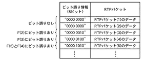
分割フィールドF(i)のビット誤り情報は、図6に示すように、各分割フィールドのビット誤りの有無を表記する1バイトの情報であり、“0”ならばビット誤りが無く、“1”ならばビット誤りが有ることを表している。
例えば、ビット誤り情報が“00000010”であれば、分割フィールドF(2)にビット誤りが有り、ビット誤り情報が“00000100”であれば、分割フィールドF(3)にビット誤りが有ることを表している。
When the redundant
However, when recording the remaining RTP packet in the data
As shown in FIG. 6, the bit error information of the divided field F (i) is 1-byte information indicating the presence / absence of a bit error in each divided field. If “0”, there is no bit error, “1” Then, it indicates that there is a bit error.
For example, if the bit error information is “00000010”, there is a bit error in the divided field F (2), and if the bit error information is “00000100”, it indicates that there is a bit error in the divided field F (3). ing.
冗長パケット識別部22は、パケット受信部21により受信されたパケットが冗長パケットであると識別すると、その冗長パケットの中からUDPヘッダを除いて、残りのRTPパケットを冗長パケット受信バッファ27に記録する(ステップST45)。
ただし、冗長パケット識別部22は、残りのRTPパケットを冗長パケット受信バッファ27に記録する際、データパケットの場合と同様に、その冗長パケットの分割フィールドF(i)のビット誤り情報をRTPパケットの先頭に付与して記録する。
When the redundant
However, the redundant
データパケット復元部28は、データパケット受信バッファ26に記録されているビット誤り情報を参照して、分割フィールドF(i)にビット誤りが存在するデータパケットを検出すると、ビット誤りが存在しない冗長パケットの分割フィールドを用いて、分割フィールドF(i)にビット誤りが存在するデータパケットを復元する(ステップST44)。
以下、データパケット復元部28におけるデータパケットの復元方法を具体的に説明する。
When the data
Hereinafter, a data packet restoration method in the data
まず、データパケット復元部28は、データパケット受信バッファ26に記録されているビット誤り情報を参照して、分割フィールドF(i)にビット誤りが存在するデータパケットを検出する。あるいは、ロスしているデータパケットを検出する(図9のステップST51〜ST55)。
以降、ビット誤りが存在するデータパケット又はロスしているデータパケットをDP(m)で表記する。
ビット誤りが存在するデータパケットの検出においては、ビット誤り情報を参照して、ビット誤りが有る分割フィールドが1つ以上あるデータパケットを検出し、そのデータパケットのRTPヘッダ中のシーケンス番号を検出する。
また、ロスしているデータパケットの検出においては、RTPヘッダのシーケンス番号に抜けがあるシーケンス番号を検出する。
なお、データパケット復元部28は、ビット誤りが存在するデータパケット又はロスしているデータパケットを検出すると、復元ができたか否かを示す復元処理フラグRFを“0”に初期化する。
ただし、復元処理フラグRF=0は復元ができていない旨を示し、復元処理フラグRF=1は復元ができていることを示すものとする。
First, the data
Hereinafter, a data packet having a bit error or a lost data packet is represented by DP (m).
In detecting a data packet having a bit error, the data packet having one or more division fields having the bit error is detected by referring to the bit error information, and the sequence number in the RTP header of the data packet is detected. .
In detecting a lost data packet, a sequence number having a missing sequence number in the RTP header is detected.
When the data
However, the restoration processing flag RF = 0 indicates that restoration has not been performed, and the restoration processing flag RF = 1 indicates that restoration has been performed.
データパケット復元部28は、ビット誤りが存在するデータパケットDP(m)又はロスしているデータパケットDP(m)があれば、冗長パケット受信バッファ27の中から、データパケットDP(m)を復元対象とする冗長パケット(以降、この冗長パケットをJP(k)で表記)を検出する(ステップST56,ST57)。
冗長パケットJP(k)の検出方法としては、例えば、送信端末1がインターネット標準規格であるRFC2733を利用して冗長パケットを送信する場合には、冗長パケットのRTP拡張ヘッダに記述されている復号対象のシーケンス番号とのマッチングによって検出する方法がある。
The data
As a detection method of the redundant packet JP (k), for example, when the transmitting
仮に、データパケットDP(m)を復元対象とする冗長パケットJP(k)が冗長パケット受信バッファ27に記録されていない場合には、データパケットDP(m)を復元することは不可能であり、また、他のデータパケットを復元するためにもデータパケットDP(m)は使用されないので、データパケット受信バッファ26からデータパケットDP(m)を削除してもよいし、上位アプリケーションが望むのであれば、ビット誤りが存在したままのデータパケットDP(m)を提供するようにしてもよい。
If the redundant packet JP (k) for which the data packet DP (m) is to be restored is not recorded in the redundant
データパケット復元部28は、データパケットDP(m)を復元対象とする冗長パケットJP(k)を検出することができなければ(ステップST58)、次のデータパケットDP(m)を検出して(ステップST59)、次のデータパケットDP(m)を復元対象とする冗長パケットJP(k)を検出する。
データパケット復元部28は、データパケットDP(m)を復元対象とする冗長パケットJP(k)を検出することができれば(ステップST58)、冗長パケット受信バッファ27の中から、冗長パケットJP(k)が復元対象としているデータパケットDP(j)を検出する(ステップST60)。
データパケットDP(j)の検出方法は、冗長パケットJP(k)の検出方法と同様に、データパケットDP(j)のRTP拡張ヘッダに記述されている復号対象のシーケンス番号を利用する。
If the data
If the data
The method for detecting the data packet DP (j) uses the sequence number to be decoded described in the RTP extension header of the data packet DP (j), as in the method for detecting the redundant packet JP (k).
次に、データパケット復元部28は、冗長パケットJP(k)とデータパケットDP(j)から、復元対象であるデータパケットDP(m)の参考パケットDPk(m)を生成する(ステップST61)。
例えば、m=j2として、冗長パケットJP(k)が復元対象としているデータパケットがDP(j1),DP(j2),DP(j3)であるとすると、冗長パケットJP(k)は下記の式(1)のようになる。ただし、式(1)において、^は排他的論理和を示す演算記号である。
JP(k)=DP(j1)^DP(j2)^DP(j3) (1)
したがって、データパケットDP(j2)を復元するには、DP(j1),DP(j3),JP(k)の排他的論理和を計算すればよい。
DPk(j2)=DP(j1)^DP(j3)^JP(k) (2)
ここでは、上記のように、冗長パケットJP(k)で復元したデータパケットDPk(j2)をデータパケットDP(m)の参考パケットDPk(m)と称する。
Next, the data
For example, if m = j2 and the data packet that the redundant packet JP (k) is to be restored is DP (j1), DP (j2), DP (j3), the redundant packet JP (k) It becomes like (1). However, in Formula (1), ^ is an operation symbol indicating exclusive OR.
JP (k) = DP (j1) ^ DP (j2) ^ DP (j3) (1)
Therefore, to restore the data packet DP (j2), an exclusive OR of DP (j1), DP (j3), and JP (k) may be calculated.
DPk (j2) = DP (j1) ^ DP (j3) ^ JP (k) (2)
Here, as described above, the data packet DPk (j2) restored by the redundant packet JP (k) is referred to as a reference packet DPk (m) of the data packet DP (m).
このとき、データパケット復元部28は、参考パケットDPk(m)の各分割フィールドが正しく復元できているか否かも調査する(ステップST62〜ST64)。
上記の例では、DP(j1),DP(j3),JP(k)のどれか1つでも、分割フィールドF(i)にビット誤りが存在すれば、参考パケットDPk(j2)の分割フィールドF(i)は正常に復元できていないことになる。
At this time, the data
In the above example, if any one of DP (j1), DP (j3), and JP (k) has a bit error in the division field F (i), the division field F of the reference packet DPk (j2). (I) is not restored normally.
次に、データパケット復元部28は、データパケットDP(m)の中でビット誤りが存在する分割フィールドF(i)において、参考パケットDPk(m)の分割フィールドF(i)にビット誤りがなければ、データパケットDP(m)の分割フィールドF(i)を参考パケットDPk(m)の分割フィールドF(i)に置き換えて(ステップST65)、データパケット受信バッファ26に対するデータパケットDP(m)の記録を更新する(ステップST65)。
また、データパケット復元部28は、データパケットDP(m)のビット誤り情報も更新する(ステップST66)。
即ち、データパケットDP(m)における分割フィールドF(i)のビット誤り情報を“0”にする(図6を参照)。
さらに、データパケット復元部28は、復元ができたか否かを示す復元処理フラグRFを“1”に設定する(ステップST67)。
Next, in the divided field F (i) in which the bit error exists in the data packet DP (m), the data
Data
That is, the bit error information of the division field F (i) in the data packet DP (m) is set to “0” (see FIG. 6).
Further, the data
データパケット復元部28は、データパケットDP(m)がロスしているデータパケットである場合、データパケットDP(m)の全ての分割フィールドF(i)にビット誤りが存在するものとして、上記の復元処理を行う。
また、データパケット復元部28は、データパケットDP(m)を復元対象とする冗長パケットJP(k)が複数ある場合(k=1,2,3,・・・)、上記の復元処理を繰り返し実行することにより、複数の参考パケットDP1(m)、DP2(m)、DP3(m)、・・・を生成して、データパケットDP(m)を復元する(ステップST58〜ST70)。
When the data packet DP (m) is a lost data packet, the data
Further, when there are a plurality of redundant packets JP (k) for which the data packet DP (m) is to be restored (k = 1, 2, 3,...), The data
データパケット復元部28は、データパケットDP(m)を復元対象とする冗長パケットJP(k)がなくなると(ステップST58)、次のビット誤りが存在するデータパケットDP(m)、あるいは、ロスしているデータパケットDP(m)を検出し(ステップST59)、上記の復元処理を繰り返し実行する。
データパケット復元部28は、データパケット受信バッファ26におけるデータパケットDP(m)の検出が一巡すると(ステップST56)、再度、データパケット受信バッファ26の先頭からデータパケットDP(m)を検索する(ステップST52)。
When there is no redundant packet JP (k) for which the data packet DP (m) is to be restored (step ST58), the data
When the detection of the data packet DP (m) in the data
このとき、データパケットDP(m)が存在しない場合、データパケットDP(m)の復元処理を終了する。
一方、データパケットDP(m)が存在する場合、復元処理フラグRF=1であれば(ステップST53)、そのデータパケットDP(m)は、前回処理で復元できたデータパケットがあるので、再度、そのデータパケットDP(m)の復元処理を試みる(ステップST54〜)。
復元処理フラグRF=0であれば(ステップST53)、再度復元処理を実施しても、復元できるデータパケットがないので、データパケットDP(m)の復元処理を終了する。
なお、データパケットDP(m)の中でビット誤りが存在する分割フィールドF(i)において、分割フィールドF(i)にビット誤りがない参考パケットDPk(m)が1つもない場合、従来の多数決法などを用いるようにしてもよい。
At this time, if the data packet DP (m) does not exist, the restoration process of the data packet DP (m) is terminated.
On the other hand, if the data packet DP (m) exists, if the restoration processing flag RF = 1 (step ST53), the data packet DP (m) has a data packet that can be restored by the previous processing. An attempt is made to restore the data packet DP (m) (from step ST54).
If the restoration process flag RF = 0 (step ST53), there is no data packet that can be restored even if the restoration process is performed again, so the restoration process of the data packet DP (m) is terminated.
If there is no reference packet DPk (m) having no bit error in the divided field F (i) in the divided field F (i) in which the bit error exists in the data packet DP (m), the conventional majority decision is performed. A method or the like may be used.
以上で明らかなように、この実施の形態1によれば、送信端末1がデータパケット及び冗長パケットにおける分割フィールドF(i)のビット誤り検出用データを算出して、そのビット誤り検出用データであるチェックサム値をデータパケット及び冗長パケットのRTPヘッダに挿入する一方、受信端末2の分割誤り検出部25がデータパケット及び冗長パケットのRTPヘッダに挿入されているチェックサム値を参照して、データパケット及び冗長パケットの分割フィールドF(i)におけるビット誤りを検出し、データパケット復元部28が分割誤り検出部25によりビット誤りが検出されていない冗長パケットの分割フィールドを用いて、分割誤り検出部25によりビット誤りが検出されたデータパケットの分割フィールドF(i)を復元するように構成したので、データパケットの伝送帯域の増加を招くことなく、ビット誤りがあるデータパケットを正しく復元することができる効果を奏する。
As apparent from the above, according to the first embodiment, the transmitting
即ち、この実施の形態1によれば、ビット誤りが存在するデータパケットDP(m)において、どの部分にビット誤りがあるのかを特定することができ、また、そのデータパケットDP(m)を復元するために生成した参考パケットDPk(m)も、どの部分にビット誤りがあるのかを特定することができるため、参考パケットDPk(m)の正しい部分だけを用いて、受信したデータパケットDP(m)を正しく復元することができる。
また、従来の多数決法のように多くの参考パケットを必要としないため、冗長パケットの送信量を削減することができる。
That is, according to the first embodiment, it is possible to specify which part has a bit error in the data packet DP (m) in which a bit error exists, and restore the data packet DP (m). Since the reference packet DPk (m) generated for the purpose can specify which part has a bit error, only the correct part of the reference packet DPk (m) is used to receive the received data packet DP (m ) Can be restored correctly.
Further, since a large number of reference packets are not required unlike the conventional majority method, the amount of redundant packets transmitted can be reduced.
実施の形態2.
上記実施の形態1では、送信端末1の分割誤り検知符号挿入部15が、RTPヘッダを拡張してチェックサムフィールドを設け、分割フィールドF(i)のチェックサム値TS(i)又は圧縮符号化後のチェックサム値CTS(i)をRTPヘッダのチェックサムフィールドに挿入するものについて示したが、図10に示すように、分割フィールドF(i)のチェックサム値TS(i)又は圧縮符号化後のチェックサム値CTS(i)をUDPヘッダのチェックサムフィールドに挿入するようにしてもよい。
In
図10は分割誤り検知符号算出部12により生成されるパケットの構成及びビット誤り検出用データであるチェックサム値の算出挿入方法を示す説明図である。
図11はパケット受信部21により受信されるパケットの構成及びビット誤りの検出方法を示す説明図である。
図12はこの発明の実施の形態2による送信端末1の処理内容を示すフローチャートである。
図13はこの発明の実施の形態2による受信端末2の処理内容を示すフローチャートである。
FIG. 10 is an explanatory diagram showing a structure of a packet generated by the division error detection
FIG. 11 is an explanatory diagram showing a configuration of a packet received by the
FIG. 12 is a flowchart showing the processing contents of the
FIG. 13 is a flowchart showing the processing contents of the receiving
次に動作について説明する。
送信端末1のソースデータ生成部11は、送信対象のマルチメディアデータ(例えば、映像、音声)であるソースデータを生成する。
分割誤り検知符号算出部12は、ソースデータ生成部11がソースデータを生成すると、ソースデータ生成部11からソースデータを入力し(図12のステップST81)、そのソースデータを予め決められた最大データサイズでフラグメントしてパケット化する(ステップST82)。
これにより、RTPヘッダ及びUDPヘッダが先頭に付加されているデータパケットが生成される(図10を参照)。
Next, the operation will be described.
The source data generation unit 11 of the
When the source data generating unit 11 generates the source data, the division error detecting
As a result, a data packet with an RTP header and a UDP header added to the head is generated (see FIG. 10).
次に、分割誤り検知符号算出部12は、データパケットであるUDPパケットを予め決められた数に区切って分割フィールドを定義する。
即ち、分割誤り検知符号算出部12は、UDPパケットを4つに分割することにより、分割フィールドF(i)を生成する(ステップST83,ST84)。ただし、i={1,2,3,4}である。
図10の例では、先頭の分割フィールドF(1)はUDPヘッダとRTPヘッダの領域であり、残りの分割フィールドF(2)、F(3)、F(4)はRTPペイロードが3等分された領域である。
Next, the division error detection
That is, the division error detection
In the example of FIG. 10, the first divided field F (1) is an area of the UDP header and the RTP header, and the remaining divided fields F (2), F (3), and F (4) are divided into three equal parts of the RTP payload. This is the area that has been
分割誤り検知符号算出部12は、分割フィールドF(i)を生成すると、各分割フィールドのビット誤り検出用データとして、分割フィールドF(i)のチェックサム値TS(i)を算出する(ステップST85〜ST88)。ただし、i={1,2,3,4}である。
図10では、16ビットのチェックサム値TS(i)を算出している例を示している。ただし、先頭の分割フィールドF(1)においては、UDPヘッダのチェックサムフィールドを“0”として、チェックサム値TS(1)を算出する。
When the division error detection
FIG. 10 shows an example in which a 16-bit checksum value TS (i) is calculated. However, in the first divided field F (1), the checksum field TS (1) is calculated with the checksum field of the UDP header set to “0”.
分割誤り検知符号挿入部15は、分割誤り検知符号算出部12がデータパケットにおける分割フィールドF(i)のチェックサム値TS(i)を算出すると、分割フィールドF(2)〜F(4)のチェックサム値TS(2)〜TS(4)を圧縮符号化する(ステップST89〜ST92)。
例えば、巡回符号方式やリード・ソロモン符号化方式などを利用して、16ビットのチェックサム値TS(2)〜TS(4)を4ビットのチェックサム値CTS(2)〜CTS(4)に圧縮符号化する。
この段階では、分割フィールドF(1)のチェックサム値CTS(1)は“0”とする(ステップST93)。
When the division error detection
For example, a 16-bit checksum value TS (2) to TS (4) is converted into a 4-bit checksum value CTS (2) to CTS (4) by using a cyclic coding method or a Reed-Solomon coding method. Compress and encode.
At this stage, the checksum value CTS (1) of the divided field F (1) is set to “0” (step ST93).
そして、分割誤り検知符号挿入部15は、圧縮符号化後のチェックサム値CTS(i)をUDPヘッダのチェックサムフィールドに挿入する(ステップST94〜ST97)。
図10では、分割フィールドF(1)のチェックサム値CTS(1)をチェックサムフィールドの0ビット目、分割フィールドF(2)のチェックサム値CTS(2)をチェックサムフィールドの4ビット目、分割フィールドF(3)のチェックサム値CTS(3)をチェックサムフィールドの8ビット目、分割フィールドF(4)のチェックサム値CTS(4)をチェックサムフィールドの12ビット目に挿入している例を示している。
ここでは、情報量を削減するため、圧縮符号化後のチェックサム値CTS(i)をUDPヘッダのチェックサムフィールドに挿入するものについて示したが、圧縮符号化前のチェックサム値TS(i)をUDPヘッダのチェックサムフィールドに挿入するようにしてもよい。
Then, the division error detecting
In FIG. 10, the checksum value CTS (1) of the divided field F (1) is the 0th bit of the checksum field, the checksum value CTS (2) of the divided field F (2) is the fourth bit of the checksum field, The checksum value CTS (3) of the divided field F (3) is inserted into the 8th bit of the checksum field, and the checksum value CTS (4) of the divided field F (4) is inserted into the 12th bit of the checksum field. An example is shown.
Although the checksum value CTS (i) after compression encoding is inserted into the checksum field of the UDP header in order to reduce the amount of information, the checksum value TS (i) before compression encoding is shown. May be inserted into the checksum field of the UDP header.
次に、分割誤り検知符号挿入部15は、分割フィールドF(1)のチェックサム値TS(1)に、UDPヘッダのチェックサムフィールドの値を加え(ステップST98)、加算後のチェックサム値TS(1)を4ビットのチェックサム値CTS(1)に圧縮符号化する(ステップST99)。
そして、分割誤り検知符号挿入部15は、再度、分割フィールドF(1)のチェックサム値CTS(1)をUDPヘッダのチェックサムフィールドの0ビット目に挿入する(ステップST100)。
Next, the division error detection
The division error detection
パケット送信部16は、分割誤り検知符号挿入部15が分割フィールドF(i)のチェックサム値CTS(i)をUDPヘッダのチェックサムフィールドに挿入すると、チェックサム値が挿入されているデータパケットを受信端末2に送信する(ステップST101)。
また、パケット送信部16は、受信端末2に送信したデータパケットの中からUDPヘッダを除いて、残りのRTPパケットを送信バッファ13に記録する(ステップST102)。
When the division error detection
Further, the
冗長データ生成部14は、送信バッファ13に記録されている複数のデータパケット(RTPパケット)の排他的論理和を演算して冗長データを生成する。
例えば、データパケットDP(1),DP(2),DP(3)におけるRTPペイロードの排他的論理和を演算して冗長データJP(1)を生成する。同様に、データパケットDP(2),DP(3),DP(4)におけるRTPペイロードの排他的論理和を演算して冗長データJP(2)を生成する。
この場合、データパケットDP(1),DP(2),DP(3)は、冗長データJP(1)の復元対象のデータパケットであり、データパケットDP(2),DP(3),DP(4)は、冗長データJP(2)の復元対象のデータパケットである。
したがって、例えば、データパケットDP(2)やDP(3)は、仮にビット誤りが受信側で発生していても、冗長データJP(1)又はJP(2)のパケットと、それらの冗長パケットが復元対象としているデータパケットをビット誤りなく受信することができていれば、正しく復元することができる。
The redundant data generation unit 14 calculates the exclusive OR of a plurality of data packets (RTP packets) recorded in the
For example, the redundant data JP (1) is generated by calculating the exclusive OR of the RTP payloads in the data packets DP (1), DP (2), and DP (3). Similarly, the exclusive OR of the RTP payloads in the data packets DP (2), DP (3), DP (4) is calculated to generate redundant data JP (2).
In this case, the data packets DP (1), DP (2), DP (3) are data packets to be restored from the redundant data JP (1), and the data packets DP (2), DP (3), DP ( 4) is a data packet to be restored of redundant data JP (2).
Therefore, for example, the data packet DP (2) or DP (3) has a redundant data JP (1) or JP (2) packet and those redundant packets even if a bit error occurs on the receiving side. If the data packet to be restored can be received without bit errors, it can be correctly restored.
分割誤り検知符号算出部12は、冗長データ生成部14が冗長データを生成すると、冗長データ生成部14から冗長データを入力し(ステップST81)、上述したソースデータの場合と同様に、その冗長データを予め決められた最大データサイズでフラグメントしてパケット化する(ステップST82)。
これにより、RTPヘッダ及びUDPヘッダが先頭に付加されている冗長パケットが生成される。
When the redundant data generation unit 14 generates redundant data, the division error detection
As a result, a redundant packet with the RTP header and UDP header added to the head is generated.
次に、分割誤り検知符号算出部12は、ソースデータの場合と同様に、冗長パケットであるUDPパケットを4つに分割することにより、分割フィールドF(i)を生成する(ステップST83、ST84)。ただし、i={1,2,3,4}である。
分割誤り検知符号算出部12は、分割フィールドF(i)を生成すると、ソースデータの場合と同様に、各分割フィールドのビット誤り検出用データとして、分割フィールドF(i)のチェックサム値TS(i)を算出する(ステップST85〜ST88)。ただし、i={1,2,3,4}である。
Next, as in the case of the source data, the division error detection
When the division error detection
分割誤り検知符号挿入部15は、分割誤り検知符号算出部12が冗長パケットにおける分割フィールドF(i)のチェックサム値TS(i)を算出すると、ソースデータの場合と同様に、分割フィールドF(2)〜F(4)のチェックサム値TS(2)〜TS(4)を圧縮符号化する(ステップST89〜ST92)。
また、この段階では、分割フィールドF(1)のチェックサム値CTS(1)は“0”とする(ステップST93)。
When the division error detection
At this stage, the checksum value CTS (1) of the divided field F (1) is set to “0” (step ST93).
分割誤り検知符号挿入部15は、圧縮符号化後のチェックサム値CTS(i)をUDPヘッダのチェックサムフィールドに挿入する(ステップST94〜ST97)。
次に、分割誤り検知符号挿入部15は、分割フィールドF(1)のチェックサム値TS(1)に、UDPヘッダのチェックサムフィールドの値を加え(ステップST98)、加算後のチェックサム値TS(1)を4ビットのチェックサム値CTS(1)に圧縮符号化する(ステップST99)。
そして、分割誤り検知符号挿入部15は、再度、分割フィールドF(1)のチェックサム値CTS(1)をUDPヘッダのチェックサムフィールドの0ビット目に挿入する(ステップST100)。
The division error detection
Next, the division error detection
The division error detection
パケット送信部16は、分割誤り検知符号挿入部15が分割フィールドF(i)のチェックサム値CTS(i)をUDPヘッダのチェックサムフィールドに挿入すると、チェックサム値が挿入されている冗長パケットを受信端末2に送信する(ステップST101)。
全てのソースデータのデータパケット及び冗長パケットの送信が完了するまで、ステップST81〜ST102の処理が繰り返し実施される(ステップST103,ST104)。
When the division error detection
The processes of steps ST81 to ST102 are repeatedly performed until the transmission of all the source data data packets and redundant packets is completed (steps ST103 and ST104).
受信端末2のパケット受信部21は、送信端末1がデータパケット又は冗長パケットを送信すると、そのデータパケット又は冗長パケットを受信する(図13のステップST111)。
分割誤り検知符号抽出部23は、パケット受信部21がデータパケット又は冗長パケットを受信すると、図11に示すように、そのデータパケット又は冗長パケットのUDPヘッダのチェックサムフィールドから圧縮符号化後のチェックサム値CTS(i)を抽出する(ステップST112〜ST115)。ただし、i={1,2,3,4}である。
When the transmitting
When the
分割誤り検知符号算出部24は、パケット受信部21がデータパケット又は冗長パケットを受信すると、そのデータパケット又は冗長パケットにおける分割フィールドF(1)のチェックサム値TSr(1)を算出する(ステップST116)。
ただし、UDPヘッダにおけるチェックサムフィールドのCTS(1)が挿入されている4ビットは“0”としてチェックサム値を算出する。
When the
However, the checksum value is calculated assuming that the 4 bits in which the CTS (1) of the checksum field in the UDP header is inserted are “0”.
分割誤り検出部25は、分割誤り検知符号算出部24が分割フィールドF(1)のチェックサム値TSr(1)を算出すると、送信端末1の分割誤り検知符号挿入部15と同じ圧縮符号化方式で、そのチェックサム値TSr(1)を圧縮符号化する(ステップST117)。
そして、分割誤り検出部25は、圧縮符号化後のチェックサム値CTSr(1)と分割誤り検知符号抽出部23により抽出された圧縮符号化後のチェックサム値CTS(1)とを比較して(ステップST118)、等しくなければ、分割フィールドF(1)にビット誤りが存在していると判断して、パケット受信部21により受信されたデータパケット又は冗長パケットを破棄する。
即ち、分割フィールドF(1)にビット誤りが存在する場合、CTSヘッダやRTPヘッダのシーケンス番号にも誤りがある可能性があり、後のデータパケットの復元ができなくなるので、パケット受信部21により受信されたデータパケット又は冗長パケットをデータパケット受信バッファ26又は冗長パケット受信バッファ27には記録せずに破棄する。
When the division error detection
Then, the division
That is, if there is a bit error in the division field F (1), there is a possibility that the sequence number of the CTS header or RTP header may also be incorrect, and the subsequent data packet cannot be restored. The received data packet or redundant packet is discarded without being recorded in the data
分割誤り検知符号算出部24は、分割誤り検出部25が分割フィールドF(1)にビット誤りが存在していないと判断すると、図11に示すように、パケット受信部21により受信されたデータパケット又は冗長パケットにおける分割フィールドF(2)〜F(4)のチェックサム値TSr(2)〜TSr(4)を算出する(ステップST119,ST120)。
If the division error detection
分割誤り検出部25は、分割誤り検知符号算出部24が分割フィールドF(2)〜F(4)のチェックサム値TSr(2)〜TSr(4)を算出すると、送信端末1の分割誤り検知符号挿入部15と同じ圧縮符号化方式で、そのチェックサム値TSr(2)〜TSr(4)を圧縮符号化する(ステップST121)。
そして、分割誤り検出部25は、圧縮符号化後のチェックサム値CTSr(2)〜CTSr(4)と分割誤り検知符号抽出部23により抽出された圧縮符号化後のチェックサム値CTS(2)〜CTS(4)とを比較して、分割フィールドF(2)〜F(4)におけるビット誤りを検出する(ステップST122〜ST125)。
即ち、分割誤り検出部25は、圧縮符号化後のチェックサム値CTSr(2)〜CTSr(4)とチェックサム値CTS(2)〜CTS(4)が等しければ、分割フィールドF(2)〜F(4)にはビット誤りがないと認定する。一方、圧縮符号化後のチェックサム値CTSr(2)〜CTSr(4)とチェックサム値CTS(2)〜CTS(4)が等しくなければ、分割フィールドF(2)〜F(4)にビット誤りがあると認定する。
The division
Then, the division
That is, if the checksum values CTSr (2) to CTSr (4) after compression encoding are equal to the checksum values CTS (2) to CTS (4), the division
分割誤り検出部25は、上記のようにして、分割フィールドF(2)〜F(4)におけるビット誤りの有無を特定すると、その分割フィールドF(2)〜F(4)のビット誤り情報を更新する。
即ち、分割誤り検出部25は、分割フィールドF(2)〜F(4)にビット誤りがあれば、その分割フィールドF(2)〜F(4)のフラグを“1”に設定する。なお、初期状態では、分割フィールドF(2)〜F(4)のフラグは“0”である。
When the division
That is, if there is a bit error in the divided fields F (2) to F (4), the divided
冗長パケット識別部22は、パケット受信部21により受信されたパケットがデータパケットであるのか、冗長パケットであるのかを識別する(ステップST126)。
例えば、送信端末1がインターネット標準規格であるRFC2733を利用して冗長パケットを送信する場合には、RTPヘッダのペイロード番号を参照すれば、パケット受信部21により受信されたパケットがデータパケットであるのか、冗長パケットであるのかを識別することができる。
The redundant
For example, when the transmitting
冗長パケット識別部22は、パケット受信部21により受信されたパケットがデータパケットであると識別すると、そのデータパケットの中からUDPヘッダを除いて、残りのRTPパケットをデータパケット受信バッファ26に記録する(ステップST127)。
ただし、冗長パケット識別部22は、残りのRTPパケットをデータパケット受信バッファ26に記録する際、そのデータパケットの分割フィールドF(i)のビット誤り情報をRTPパケットの先頭に付与して記録する。
分割フィールドF(i)のビット誤り情報は、図6に示すように、各分割フィールドのビット誤りの有無を表記する1バイトの情報であり、“0”ならばビット誤りが無く、“1”ならばビット誤りが有ることを表している。
例えば、ビット誤り情報が“00000010”であれば、分割フィールドF(2)にビット誤りが有り、ビット誤り情報が“00000100”であれば、分割フィールドF(3)にビット誤りが有ることを表している。
When the redundant
However, when recording the remaining RTP packet in the data
As shown in FIG. 6, the bit error information of the divided field F (i) is 1-byte information indicating the presence / absence of a bit error in each divided field. If “0”, there is no bit error, “1” Then, it indicates that there is a bit error.
For example, if the bit error information is “00000010”, there is a bit error in the divided field F (2), and if the bit error information is “00000100”, it indicates that there is a bit error in the divided field F (3). ing.
冗長パケット識別部22は、パケット受信部21により受信されたパケットが冗長パケットであると識別すると、その冗長パケットの中からUDPヘッダを除いて、残りのRTPパケットを冗長パケット受信バッファ27に記録する(ステップST129)。
ただし、冗長パケット識別部22は、残りのRTPパケットを冗長パケット受信バッファ27に記録する際、データパケットの場合と同様に、その冗長パケットの分割フィールドF(i)のビット誤り情報をRTPパケットの先頭に付与して記録する。
When the redundant
However, the redundant
データパケット復元部28は、データパケット受信バッファ26に記録されているビット誤り情報を参照して、分割フィールドF(i)にビット誤りが存在するデータパケットを検出すると、上記実施の形態1と同様に、ビット誤りが存在しない冗長パケットの分割フィールドを用いて、分割フィールドF(i)にビット誤りが存在するデータパケットを復元する(ステップST128)。
When the data
以上で明らかなように、この実施の形態2によれば、ビット誤りが存在するデータパケットDP(m)において、どの部分にビット誤りがあるのかを特定することができ、また、そのデータパケットDP(m)を復元するために生成した参考パケットDPk(m)も、どの部分にビット誤りがあるのかを特定することができるため、参考パケットDPk(m)の正しい部分だけを用いて、受信したデータパケットDP(m)を正しく復元することができる。
また、従来の多数決法のように多くの参考パケットを必要としないため、冗長パケットの送信量を削減することができる。
さらに、分割フィールド毎の誤り検知用符号データをUDPヘッダのチェックサムフィールドに挿入することができるため、オーバーヘッドを招くことなく、データパケットの復元処理を実現することができる。
As is apparent from the above, according to the second embodiment, it is possible to specify which part has a bit error in the data packet DP (m) in which a bit error exists, and the data packet DP. Since the reference packet DPk (m) generated to restore (m) can identify which part has a bit error, it is received using only the correct part of the reference packet DPk (m). The data packet DP (m) can be correctly restored.
Further, since a large number of reference packets are not required unlike the conventional majority method, the amount of redundant packets transmitted can be reduced.
Furthermore, since the error detection code data for each divided field can be inserted into the checksum field of the UDP header, data packet restoration processing can be realized without incurring overhead.
1 送信端末、2 受信端末、3 ネットワーク、11 ソースデータ生成部(ソースデータ生成手段)、12 分割誤り検知符号算出部(第1の検出用データ算出手段、第2の検出用データ算出手段、検出用データ挿入手段)、13 送信バッファ(冗長データ生成手段)、14 冗長データ生成部(冗長データ生成手段)、15 分割誤り検知符号挿入部(第1の検出用データ挿入手段、第2の検出用データ挿入手段、検出用データ挿入手段)、16 パケット送信部(パケット送信手段)、21 パケット受信部(パケット受信手段)、22 冗長パケット識別部、23 分割誤り検知符号抽出部(ビット誤り検出用データ抽出手段、誤り検出手段)、24 分割誤り検知符号算出部(ビット誤り検出用データ算出手段、誤り検出手段)、25 分割誤り検出部(ビット誤り検出手段、誤り検出手段)、26 データパケット受信バッファ、27 冗長パケット受信バッファ、28 データパケット復元部(パケット復元手段)。
DESCRIPTION OF
Claims (7)
Priority Applications (1)
| Application Number | Priority Date | Filing Date | Title |
|---|---|---|---|
| JP2007021481A JP2008187646A (en) | 2007-01-31 | 2007-01-31 | Packet communication system, transmitting terminal and receiving terminal |
Applications Claiming Priority (1)
| Application Number | Priority Date | Filing Date | Title |
|---|---|---|---|
| JP2007021481A JP2008187646A (en) | 2007-01-31 | 2007-01-31 | Packet communication system, transmitting terminal and receiving terminal |
Publications (1)
| Publication Number | Publication Date |
|---|---|
| JP2008187646A true JP2008187646A (en) | 2008-08-14 |
Family
ID=39730357
Family Applications (1)
| Application Number | Title | Priority Date | Filing Date |
|---|---|---|---|
| JP2007021481A Pending JP2008187646A (en) | 2007-01-31 | 2007-01-31 | Packet communication system, transmitting terminal and receiving terminal |
Country Status (1)
| Country | Link |
|---|---|
| JP (1) | JP2008187646A (en) |
Cited By (1)
| Publication number | Priority date | Publication date | Assignee | Title |
|---|---|---|---|---|
| JP2015532020A (en) * | 2012-06-18 | 2015-11-05 | マイクロソフト コーポレーション | Method and apparatus for error recovery using information associated with a transmitter |
Citations (2)
| Publication number | Priority date | Publication date | Assignee | Title |
|---|---|---|---|---|
| JPH05304516A (en) * | 1992-04-27 | 1993-11-16 | Kokusai Electric Co Ltd | How to edit received data |
| JP2003522474A (en) * | 2000-02-04 | 2003-07-22 | テレフォンアクチーボラゲット エル エム エリクソン(パブル) | An alternative to transport layer checksum in checksum-based header compression |
-
2007
- 2007-01-31 JP JP2007021481A patent/JP2008187646A/en active Pending
Patent Citations (2)
| Publication number | Priority date | Publication date | Assignee | Title |
|---|---|---|---|---|
| JPH05304516A (en) * | 1992-04-27 | 1993-11-16 | Kokusai Electric Co Ltd | How to edit received data |
| JP2003522474A (en) * | 2000-02-04 | 2003-07-22 | テレフォンアクチーボラゲット エル エム エリクソン(パブル) | An alternative to transport layer checksum in checksum-based header compression |
Cited By (1)
| Publication number | Priority date | Publication date | Assignee | Title |
|---|---|---|---|---|
| JP2015532020A (en) * | 2012-06-18 | 2015-11-05 | マイクロソフト コーポレーション | Method and apparatus for error recovery using information associated with a transmitter |
Similar Documents
| Publication | Publication Date | Title |
|---|---|---|
| JP6523249B2 (en) | Method and apparatus for compressing packet header | |
| JP3617967B2 (en) | Header compressed packet receiving apparatus and method | |
| JP3600189B2 (en) | Packet transmitting / receiving apparatus and packet transmitting method | |
| US9166931B2 (en) | Method and device for improving robustness of context update message in robust header compression | |
| KR100667739B1 (en) | Wireless data transceiver and method | |
| US9246630B2 (en) | Method, device, and system for forward error correction | |
| CN101296055B (en) | Data package dispatching method and device | |
| CN101707616B (en) | Method and device for compressing and decompressing user datagram protocol data packet | |
| KR100861900B1 (en) | Video decoding method, video decoding system, video demultiplexer, wireless communication device, and computer-readable medium with efficient data recovery | |
| US7983252B2 (en) | Enhanced frame aggregation in a wireless network system | |
| US20140223030A1 (en) | Data compression for priority based data traffic, on an aggregate traffic level, in a multi stream communications system | |
| JP2001502142A (en) | Apparatus and method for transmitting IP data over a satellite network | |
| JP2001025010A (en) | Multimedia information communication apparatus and method | |
| KR20010005484A (en) | Encoding method for radio transceiving of multimedia data and device thereof | |
| KR20160074530A (en) | Apparatus for transmitting broadcast signal, apparatus for receiving broadcast signal, method for transmitting broadcast signal and method for receiving broadcast signal | |
| CN101453463A (en) | Data packet packing, transmitting and receiving method for mobile multimedia broadcast system | |
| JP2008187646A (en) | Packet communication system, transmitting terminal and receiving terminal | |
| JP2003324733A (en) | Moving image transmitting / receiving system and moving image transmitting / receiving method | |
| US7839925B2 (en) | Apparatus for receiving packet stream | |
| JP7663456B2 (en) | Transmitting device, receiving device and program | |
| US20040114599A1 (en) | Massive packet transmitter in wide area network and transmitting and receiving method thereof | |
| US9525650B2 (en) | Method and system for updating reorder depth in robust header compression | |
| KR100406232B1 (en) | Method for Transmission Error Notification in VoDSL Gateway | |
| KR102086457B1 (en) | A decoding method of software modem in limited memory environment, using overlapping fragmentation and progressive decoding | |
| JP2004349820A (en) | Image encoding device and image encoding method, streaming device, and computer program |
Legal Events
| Date | Code | Title | Description |
|---|---|---|---|
| RD04 | Notification of resignation of power of attorney |
Free format text: JAPANESE INTERMEDIATE CODE: A7424 Effective date: 20080704 |
|
| A621 | Written request for application examination |
Free format text: JAPANESE INTERMEDIATE CODE: A621 Effective date: 20091014 |
|
| A977 | Report on retrieval |
Free format text: JAPANESE INTERMEDIATE CODE: A971007 Effective date: 20110729 |
|
| A131 | Notification of reasons for refusal |
Free format text: JAPANESE INTERMEDIATE CODE: A131 Effective date: 20110809 |
|
| A02 | Decision of refusal |
Free format text: JAPANESE INTERMEDIATE CODE: A02 Effective date: 20111206 |