JP2008174075A - Vehicle periphery-monitoring device, and its displaying method - Google Patents
Vehicle periphery-monitoring device, and its displaying method Download PDFInfo
- Publication number
- JP2008174075A JP2008174075A JP2007008940A JP2007008940A JP2008174075A JP 2008174075 A JP2008174075 A JP 2008174075A JP 2007008940 A JP2007008940 A JP 2007008940A JP 2007008940 A JP2007008940 A JP 2007008940A JP 2008174075 A JP2008174075 A JP 2008174075A
- Authority
- JP
- Japan
- Prior art keywords
- vehicle
- display
- display area
- image
- range
- Prior art date
- Legal status (The legal status is an assumption and is not a legal conclusion. Google has not performed a legal analysis and makes no representation as to the accuracy of the status listed.)
- Pending
Links
- 238000012806 monitoring device Methods 0.000 title claims abstract description 21
- 238000000034 method Methods 0.000 title claims description 16
- 238000003384 imaging method Methods 0.000 claims description 22
- 238000012544 monitoring process Methods 0.000 claims description 4
- 238000006243 chemical reaction Methods 0.000 claims description 3
- 238000012545 processing Methods 0.000 description 38
- 230000006835 compression Effects 0.000 description 10
- 238000007906 compression Methods 0.000 description 10
- 238000010586 diagram Methods 0.000 description 9
- NJPPVKZQTLUDBO-UHFFFAOYSA-N novaluron Chemical compound C1=C(Cl)C(OC(F)(F)C(OC(F)(F)F)F)=CC=C1NC(=O)NC(=O)C1=C(F)C=CC=C1F NJPPVKZQTLUDBO-UHFFFAOYSA-N 0.000 description 2
- 240000004050 Pentaglottis sempervirens Species 0.000 description 1
- 235000004522 Pentaglottis sempervirens Nutrition 0.000 description 1
- 230000005540 biological transmission Effects 0.000 description 1
- 230000004397 blinking Effects 0.000 description 1
- 238000004891 communication Methods 0.000 description 1
- 238000007796 conventional method Methods 0.000 description 1
- 238000005516 engineering process Methods 0.000 description 1
- 238000009434 installation Methods 0.000 description 1
- 239000004973 liquid crystal related substance Substances 0.000 description 1
- 230000004044 response Effects 0.000 description 1
Images
Landscapes
- Controls And Circuits For Display Device (AREA)
- Traffic Control Systems (AREA)
- Image Analysis (AREA)
- Fittings On The Vehicle Exterior For Carrying Loads, And Devices For Holding Or Mounting Articles (AREA)
- Image Processing (AREA)
- Closed-Circuit Television Systems (AREA)
Abstract
Description
本発明は、車両周辺を監視するための技術に関する。 The present invention relates to a technique for monitoring the periphery of a vehicle.
車両に搭載したカメラにより車両周辺の画像を取得し、取得した画像を表示装置に表示することで、車両周辺の監視を可能とする装置がある(特許文献1等参照)。
There is an apparatus that enables monitoring of the periphery of a vehicle by acquiring an image around the vehicle with a camera mounted on the vehicle and displaying the acquired image on a display device (see
しかし、従来の技術では、撮像した画像を十分に利用しているとは言えない。具体的には、従来の技術では、カメラで撮像した画像のうち、車両付近の所定範囲の画像のみを表示する。そのため、撮像していても表示に生かされない画像がある。これでは、障害物を撮像していても、ユーザ(ドライバー)に障害物の存在を知らせることができない場合がある。 However, in the conventional technology, it cannot be said that the captured image is sufficiently utilized. Specifically, in the conventional technique, only images in a predetermined range near the vehicle are displayed among images captured by the camera. Therefore, there are images that are not used for display even if they are captured. In this case, even if an obstacle is imaged, the user (driver) may not be notified of the presence of the obstacle.
本発明は、上記課題を解決すべくなされたものであり、撮像した画像を、表示の際により有効に利用することを目的とする。 The present invention has been made to solve the above-described problems, and an object thereof is to more effectively use captured images at the time of display.
上記課題を解決すべく、本発明は、撮像画像のうち、画面に収まりきれない部分を圧縮して表示する。 In order to solve the above-described problems, the present invention compresses and displays a portion of the captured image that does not fit on the screen.
例えば、本発明の車両周辺監視装置は、車両に搭載されたカメラから前記車両の周辺の撮像画像を取得する撮像画像取得手段と、表示装置の画面上に、第1の表示エリアと第2の表示エリアとを設け、前記第1の表示エリアに、前記車両の周辺の第1の範囲の撮像画像を表示し、前記第2の表示エリアに、前記第1の範囲より外にある第2の範囲の撮像画像を圧縮して表示する表示手段とを備える。 For example, the vehicle periphery monitoring device of the present invention includes a captured image acquisition unit that acquires a captured image of the periphery of the vehicle from a camera mounted on the vehicle, a first display area, and a second display on the screen of the display device. A display area, a captured image of a first range around the vehicle is displayed in the first display area, and a second area outside the first range is displayed in the second display area. Display means for compressing and displaying the captured image of the range.
また、本発明の車両周辺監視装置は、車両に搭載されたカメラから車両周辺の撮像画像を取得する手段と、前記カメラの視点位置と撮像方向に関する情報を取得する手段と、前記カメラの視点位置と撮像方向に基づいて、前記カメラの撮像画像を地上面に投影した地上投影画像に変換する画像変換手段と、表示装置の画面上に、第1の表示エリアと第2の表示エリアとを設け、前記第1の表示エリアに、車両周辺の第1の範囲に相当する、前記地上投影画像を表示し、前記第2の表示エリアに、前記車両からみて前記第1の範囲より外側の第2の範囲に相当する前記地上投影画像を、予め定めた方法により圧縮して表示する表示手段とを備える。 In addition, the vehicle periphery monitoring device of the present invention includes means for acquiring a captured image around the vehicle from a camera mounted on the vehicle, means for acquiring information regarding the viewpoint position and imaging direction of the camera, and the viewpoint position of the camera. And a first display area and a second display area on the screen of the display device, and an image conversion means for converting the image captured by the camera into a ground projection image projected on the ground surface based on the imaging direction. The ground display image corresponding to a first range around the vehicle is displayed in the first display area, and a second outside the first range as viewed from the vehicle is displayed in the second display area. Display means for compressing and displaying the ground projection image corresponding to the above range by a predetermined method.
以下に、本発明の一実施形態について、図面を参照して説明する。 An embodiment of the present invention will be described below with reference to the drawings.
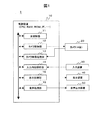
図1は、本発明の一実施形態が適用された車両周辺監視装置1の概略構成図である。図示するように、車両に搭載される車両周辺監視装置1は、制御装置10と、カメラ20と、入力装置30と、表示装置40と、音声出力装置50とを備えて構成される。
FIG. 1 is a schematic configuration diagram of a vehicle
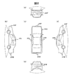
カメラ20は、車両周辺(近傍)の画像を取得するための撮像装置である。図2(a)、(b)、(c)、(d)、及び(e)は、車両の正面、右側面、上面、左側面、背面からみた様子を示す。図示すように、カメラ20は、車両500の前後左右に搭載された4台の小型カメラ20F、20B、20L、20Rからなる。それぞれのカメラ20F、20B、20L、20Rは、やや下を向いており、車両の前方、後方、左側方向、右側方向の地上面を撮像する。カメラ20は、台座の回転により撮像範囲の変更が可能である。台座の回転は、モータにより行われ、後述するカメラ制御部12で制御される。
The
図1に戻って説明する。入力装置30は、ユーザからの指示を受け付けるための装置であり、タッチパネルやハードスイッチなどで構成される。
Returning to FIG. The
表示装置40は、液晶表示装置などからなり、制御装置10で生成されたグラフィックス情報を表示するユニットである。
The
音声出力装置50は、スピーカなどからなり、制御装置10で生成された音声情報を出力するユニットである。
The
制御装置10は、他の装置(カメラ20、入力装置30、表示装置40、音声出力装置50など)を制御するための装置である。制御装置10は、CPU(Central Processing Unit)、RAM(Random Access Memory)、ROM(Read Only Memory)、他の装置(カメラ20、入力装置30、表示装置40、音声出力装置50など)とのインターフェース、これらを接続するバス、などからなる汎用的なコンピュータシステムにより構成される。
The
制御装置10は、その機能部として、主制御部11と、カメラ制御部12と、カメラ画像処理部13と、入力内容解析部14と、表示処理部15と、音声処理部16と、を備える。これらの機能部は、CPUがメモリにロードした所定のプログラムを実行することにより達成される。そのため、ROMには、各処理を行うためのプログラムが記憶されている。
The
主制御部11は、様々な処理を行う中心的ユニットである。例えば、カメラ制御部12に、カメラ20の制御を指示する。また、カメラ画像処理部13に、カメラ20で撮像した画像を取得するように指示したり、取得した画像を、地上面に投影した画像(「地上投影画像」という)に変換するように指示したりする。また、入力内容解析部14を介してユーザからの要求を受け付け、受け付けた要求に対応する処理が実行されるように、各機能部を制御する。また、表示処理部15を介して、表示装置40に、画像の表示を行う。また、音声処理部16を介して、音声出力装置50から、音声の出力を行う。
The
カメラ制御部12は、各カメラ20の動作を制御する。例えは、各カメラ20の撮像の開始・終了タイミングや、撮像範囲を設定する。また、撮像した画像のカメラ画像処理部13への送信を制御する。また、各カメラ20の撮像範囲を特定するための情報として、各カメラ20の視点位置及び撮像方向を、カメラ画像処理部13に送る。なお、カメラ制御部12は、車両内の所定の位置を基準とした各カメラ20の設置位置を予め記憶している。カメラ20の向きを変更した場合は、変更した角度に基づいて、視点位置及び撮像方向を算出し直す。
The
カメラ画像処理部13は、各カメラ20で撮像した画像を、画像データとして取得する。また、各カメラ20の撮像範囲を特定する情報(視点位置、撮像方向)に基づいて、各カメラ20から取得した画像を、公知の方法により、地上投影画像に変換する。
The camera
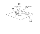
図3は、地上投影画像の生成方法を説明するための図である。カメラ画像処理部13は、カメラ制御部12から、各カメラ20の視点Pの位置(車両内の所定位置を原点とする三次元空間における座標位置)と視線方向(撮像方向)Kを取得している。撮像方向Kは、撮像画像510の中心と垂直に交わる。また、カメラの視点Pから撮像画像510までの距離は、予め定められている。カメラ画像処理部13は、撮像画像510を、カメラ20の視点Pの位置から撮像方向Kに向けて、地上面520に投影し、地上投影画像530を生成する。こうして生成される地上投影画像530は、車両の上空から車両周辺を鳥瞰したような画像となる。
FIG. 3 is a diagram for explaining a method of generating a ground projection image. The camera
図1に戻って説明する。入力内容解析部14は、入力装置30を介して入力されたユーザからの要求を解析し、その結果を主制御部11に送る。
Returning to FIG. The input
表示処理部15は、表示装置40に、ユーザからの指示を受け付けるためのメニューや、カメラ画像処理部13で生成された車両周辺の地上投影画像を表示する。また、後述するように、表示処理部15は、車両周辺の地上投影画像のうち、車両を中心とする所定範囲内については、そのまま表示する。一方、所定範囲外については、圧縮して表示する。
The
音声処理部16は、主制御部11からの指示に従って、音声出力装置50を介して、警告音や、ユーザに対するメッセージを音声出力する。
The
[動作の説明]次に、本実施形態の車両周辺監視装置1の特徴的な動作について説明する。
[Description of Operation] Next, the characteristic operation of the vehicle
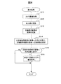
図4は、車両周辺の画像を表示する処理のフロー図である。 FIG. 4 is a flowchart of processing for displaying an image around the vehicle.
このフローは、ユーザから入力装置30を介して、車両周辺の画像を表示するように要求された場合に、定期的に行われる。
This flow is periodically performed when a user requests to display an image around the vehicle via the
まず、カメラ画像処理部13は、各カメラ20F、20B、20L、20Rから、撮像して得られた画像(「カメラ画像」という)を取得する(S11)。
First, the camera
次に、カメラ画像処理部13は、取得した各カメラ画像に基づいて、上述したように、地上投影画像を生成する。
Next, the camera
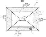
図5は、生成された地上投影画像210を示す。地上投影画像210は、4台のカメラ20F、20B、20L、20Rの画像から生成される。したがって、車両周辺の地上投影画像210は、車両501の周辺を4つに分割したエリアに対応した4つの画像(前方エリア画像210F、後方エリア画像210B、左側エリア画像210L,右側エリア画像210R)からなる。
FIG. 5 shows the generated
次に、カメラ画像処理部13は、地上投影画像210の一部を圧縮する処理を行う(図4のS13)。
Next, the camera
具体的には、カメラ画像処理部13は、車両周辺の地上投影画像210に対して、圧縮せずに表示する範囲(「非圧縮表示範囲」という)211と、圧縮して表示する範囲(「圧縮表示範囲」という)212とを設定する。例えば、カメラ画像処理部13は、車両501を中心として、所定の大きさの長方形を設定して、非圧縮表示範囲211とする。その外側に、さらに大きい、所定の大きさの長方形を設定して、その長方形内のうち非圧縮表示範囲211を除く範囲を、圧縮表示範囲212とする。
Specifically, the camera
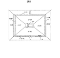
そして、カメラ画像処理部13は、圧縮表示範囲212に含まれている地上投影画像212F、212B、212L,212Rを、図6に示すように、車両の位置する方向に向けて、所定のサイズになるように圧縮し、圧縮画像213F、213B、213L、213Rを生成する。具体的には、車両501の前方の圧縮表示範囲212の地上投影画像212Fについては、車両の後方向に圧縮する。車両501の後方の圧縮表示範囲212の地上投影画像212Bについては、車両の前方向に圧縮する。車両501の左側の圧縮表示エリア212の地上投影画像212Lについては、車両501の右方向に圧縮する。車両501の右側の圧縮表示エリア212の地上投影画像212Rについては、車両501の左方向に圧縮する。
Then, the camera
カメラ画像処理部13は、例えば、圧縮方向の複数のドットを1つのドットに纏めることで画像の圧縮を行う。このとき、圧縮する複数のドットの色諧調の平均値を圧縮後の1つのドットの色諧調とする。
For example, the camera
このような圧縮によれば、図5及び図6に示すように、圧縮表示範囲212の地上投影画像212Lに障害物Qが含まれている場合でも、圧縮画像213Lに障害物Qの形跡が残される。
According to such compression, as shown in FIGS. 5 and 6, even when the obstacle Q is included in the
こうして一部を圧縮した地上投影画像が生成されると、主制御部11は、表示処理部15に、車両周辺の画像を表示するように指示する。
When a ground projection image partially compressed in this way is generated, the
これを受けて、表示処理部15は、表示装置40の表示画面400に車両周辺を示す画像を表示する(図4のS14)。
In response to this, the
図7は、表示画面の一例を示す図である。 FIG. 7 is a diagram illustrating an example of a display screen.
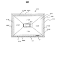
図示するように、表示処理部15は、表示画面400のほぼ中央に、車両を示すアイコン(「車両アイコン」という)401を表示する。また、車両アイコン401を中心にして外側に向かって順番に、非圧縮画像を表示するためのエリア(「非圧縮画像表示エリア」という)410と、圧縮画像を表示するためのエリア(「圧縮画像表示エリア」という)420と、警告を表示するためのエリア(「警告表示エリア」という)430とを設ける。そして、非圧縮画像表示エリア410に、非圧縮表示範囲211の地上投影画像211F、211B、211L、211Rを、車両401に対する位置に対応させて、それぞれ表示する。また、圧縮画像表示エリア420に、S13で生成した圧縮画像213F、213B、213L、213Rを、車両401に対する位置に対応させて、それぞれ表示する。
As shown in the figure, the
次に、表示処理部15は、圧縮表示範囲212の地上投影画像210(圧縮後の画像でもよい)に大きな変化があったか否か判定する(図4のS15)。
Next, the
そのため、カメラ画像処理部13は、前回の表示処理において生成した地上投影画像210を保存している。表示処理部15は、前回の表示処理にてカメラ画像処理部13にて保存していた圧縮表示範囲212の地上投影画像210と、今回S12にて生成された圧縮表示範囲212の地上投影画像210について、対応するドットごとに、色諧調値の変化を求める。このとき、地上投影画像212F、212B、212L、212Rごとに、変化の合計を求め、合計が所定の値を超えるか否か判定し、超える場合に、大きな変化があったと判定する。
Therefore, the camera
圧縮表示範囲212の地上投影画像212F、212B、212L、212Rのいずれか(ただし、2以上の場合もある)所定の変化があった場合(S16)、表示処理部15は、変化があった地上投影画像212F、212B、212L、212Rに対応する警告エリア430(430F、430B、430L、430R)に、所定の警告表示を行う。このとき、主制御部11は、音声処理部16を介して、音声出力装置50に、警告を示す効果音やメッセージを出力してもよい。
If any of the
図7では、車両の右方向の圧縮表示範囲212の地上投影画像212Lに、新たに障害物Qが入り込んだ場合に、車両の右側方向に対応する警告エリア430Lに、警告を促すべく点滅表示431を行っている様子を示している。
In FIG. 7, when a new obstacle Q enters the
以上、図4で示したフローについて説明した。 The flow shown in FIG. 4 has been described above.
本実施形態によれば、そのまま表示しようとしても表示画面に収めることができない撮像画像を圧縮して表示する。したがって、撮像した画像を、なるべく表示に寄与させることができる。これによりユーザは、障害物の存在をより着実に知ることができる。 According to the present embodiment, a captured image that cannot be displayed on the display screen even if it is displayed as it is is compressed and displayed. Therefore, the captured image can contribute to display as much as possible. Thereby, the user can know the existence of an obstacle more steadily.
本実施形態では、車両の近くは、そのまま表示し、遠い部分のみを圧縮して表示する。圧縮して表示すると多少画像の鮮明性が低下するが、遠い部分では、障害物の存在が分かればよいので、問題とならない。 In this embodiment, the vicinity of the vehicle is displayed as it is, and only a distant part is compressed and displayed. When the image is compressed and displayed, the sharpness of the image is somewhat lowered. However, since it is only necessary to know the presence of an obstacle at a distant portion, there is no problem.
また、圧縮して表示する範囲において障害物が進入するなどの変化が生じた場合に、撮像画像とは別に、警告を表示する。これによりユーザに対して、注意を喚起することができる。また、警告は、撮像方向に対応して表示されるので、ユーザに注意を喚起すべき方向を容易に知らせることができる。 In addition, a warning is displayed separately from the captured image when a change occurs such as an obstacle entering the range to be compressed and displayed. Thereby, a user can be alerted. In addition, since the warning is displayed corresponding to the imaging direction, it is possible to easily notify the user of the direction to call attention.
なお、本発明は、経路探索や経路誘導を行う車載用ナビゲーション装置に適用することができる。 The present invention can be applied to a vehicle-mounted navigation device that performs route search and route guidance.
また、通信ネットワークにより撮像画像を外部の機器に送信して、外部の機器において、上記した方法で撮像画像を表示するようにしてもよい。 Alternatively, the captured image may be transmitted to an external device via a communication network, and the captured image may be displayed on the external device by the method described above.
1…車両周辺監視装置、
10…制御装置、11…主制御部、12…カメラ制御部、13…カメラ画像処理部、14…入力内容解析部、15…表示処理部、16…音声処理部、
20…カメラ、
30…入力装置、
40…表示装置、
50…音声出力装置
1 ... Vehicle periphery monitoring device,
DESCRIPTION OF
20 ... Camera,
30 ... Input device,
40. Display device,
50. Audio output device
Claims (8)
車両に搭載されたカメラから前記車両の周辺の撮像画像を取得する撮像画像取得手段と、
表示装置の画面上に、第1の表示エリアと第2の表示エリアとを設け、
前記第1の表示エリアに、前記車両の周辺の第1の範囲の撮像画像を表示し、前記第2の表示エリアに、前記第1の範囲より外にある第2の範囲の撮像画像を圧縮して表示する表示手段と
を備えることを特徴とする車両周辺監視装置。 A vehicle periphery monitoring device,
Captured image acquisition means for acquiring a captured image around the vehicle from a camera mounted on the vehicle;
A first display area and a second display area are provided on the screen of the display device,
A captured image of a first range around the vehicle is displayed in the first display area, and a captured image of a second range outside the first range is compressed in the second display area. A vehicle periphery monitoring device comprising display means for displaying the information.
前記表示手段は、
前記第2の範囲の撮像画像を、車両の存在する方向に圧縮して表示する
ことを特徴とする車両周辺監視装置。 The vehicle periphery monitoring device according to claim 1,
The display means includes
The vehicle periphery monitoring device, wherein the captured image of the second range is compressed and displayed in a direction in which the vehicle exists.
前記撮像画像取得手段は、
複数のカメラによる複数の撮像範囲の撮像画像をそれぞれ取得し、
前記第1の表示エリアは、画面上の車両位置の周囲のエリアであり、
前記第2の表示エリアは、前記第1の表示エリアの周囲のエリアであり、
前記表示手段は、
前記第1の表示エリア及び前記第2の表示エリアに、取得した複数の撮像画像を、その撮像範囲の位置が前記画面上の車両位置を基準とした位置に対応するように表示する
ことを特徴とする車両周辺監視装置。 The vehicle periphery monitoring device according to claim 1,
The captured image acquisition means includes:
Acquire captured images of multiple imaging ranges with multiple cameras,
The first display area is an area around the vehicle position on the screen;
The second display area is an area around the first display area,
The display means includes
A plurality of acquired captured images are displayed in the first display area and the second display area so that the position of the imaging range corresponds to a position based on the vehicle position on the screen. A vehicle periphery monitoring device.
前記第2の範囲の画像の変化を判定する変化判定手段を備え、
前記表示手段は、
前記変化判定手段により前記第2の範囲の画像に所定の変化があったと判定された場合、警告の表示を行う
ことを特徴とする車両周辺監視装置。 The vehicle periphery monitoring device according to claim 1,
A change determining means for determining a change in the image in the second range;
The display means includes
A vehicle periphery monitoring apparatus that displays a warning when it is determined by the change determining means that a predetermined change has occurred in the image in the second range.
前記表示手段は、
画面上の車両位置に対応させて、前記第2の範囲の画像の圧縮画像を表示し、
前記警告を、変化が判定された画像の表示位置に対応させて、表示する
ことを特徴とする車両周辺監視装置。 The vehicle periphery monitoring device according to claim 4,
The display means includes
In correspondence with the vehicle position on the screen, a compressed image of the image in the second range is displayed,
A vehicle periphery monitoring device, characterized in that the warning is displayed in correspondence with a display position of an image whose change is determined.
前記カメラの視点位置と撮像方向に関する情報を取得する手段と、
前記カメラの視点位置と撮像方向に基づいて、前記カメラの撮像画像を地上面に投影した地上投影画像に変換する画像変換手段と、
表示装置の画面上に、第1の表示エリアと第2の表示エリアとを設け、
前記第1の表示エリアに、車両周辺の第1の範囲に相当する、前記地上投影画像を表示し、
前記第2の表示エリアに、前記車両からみて前記第1の範囲より外側の第2の範囲に相当する前記地上投影画像を、予め定めた方法により圧縮して表示する表示手段と
を備えることを特徴とする車両周辺監視装置。 Means for obtaining a captured image around the vehicle from a camera mounted on the vehicle;
Means for obtaining information on the viewpoint position and imaging direction of the camera;
Image conversion means for converting a captured image of the camera into a ground projection image projected on the ground surface based on a viewpoint position and an imaging direction of the camera;
A first display area and a second display area are provided on the screen of the display device,
Displaying the ground projection image corresponding to a first range around the vehicle in the first display area;
Display means for compressing and displaying the ground projection image corresponding to the second range outside the first range as viewed from the vehicle in the second display area by a predetermined method. A vehicle periphery monitoring device.
車両に搭載されたカメラから前記車両の周辺の撮像画像を取得する撮像画像取得ステップと、
表示装置の画面上に、第1の表示エリアと第2の表示エリアとを設け、
前記第1の表示エリアに、前記車両の周辺の第1の範囲の撮像画像を表示し、前記第2の表示エリアに、前記第1の範囲より外にある第2の範囲の撮像画像を圧縮して表示する表示ステップと
を備えることを特徴とする車両周辺監視装置の表示方法。 A display method for a vehicle periphery monitoring device,
A captured image acquisition step of acquiring a captured image around the vehicle from a camera mounted on the vehicle;
A first display area and a second display area are provided on the screen of the display device,
A captured image of a first range around the vehicle is displayed in the first display area, and a captured image of a second range outside the first range is compressed in the second display area. And a display step for displaying the information on the vehicle.
車両に搭載されたカメラから車両周辺の撮像画像を取得するステップと、
前記カメラの視点位置と撮像方向に関する情報を取得するステップと、
前記カメラの視点位置と撮像方向に基づいて、前記カメラの撮像画像を地上面に投影した地上投影画像に変換する画像変換ステップと、
表示装置の画面上に、第1の表示エリアと第2の表示エリアとを設け、
前記第1の表示エリアに、車両周辺の第1の範囲に相当する、前記地上投影画像を表示し、
前記第2の表示エリアに、前記車両からみて前記第1の範囲より外側の第2の範囲に相当する前記地上投影画像を、予め定めた方法により圧縮して表示する表示ステップと
を備えることを特徴とする車両周辺監視装置の表示方法。 A display method for a vehicle periphery monitoring device,
Obtaining a captured image around the vehicle from a camera mounted on the vehicle;
Obtaining information regarding the viewpoint position and imaging direction of the camera;
An image conversion step for converting a captured image of the camera into a ground projection image projected on the ground surface based on the viewpoint position and imaging direction of the camera;
A first display area and a second display area are provided on the screen of the display device,
Displaying the ground projection image corresponding to a first range around the vehicle in the first display area;
A display step of compressing and displaying the ground projection image corresponding to the second range outside the first range as viewed from the vehicle by the predetermined method in the second display area. A display method of a vehicle periphery monitoring device as a feature.
Priority Applications (1)
| Application Number | Priority Date | Filing Date | Title |
|---|---|---|---|
| JP2007008940A JP2008174075A (en) | 2007-01-18 | 2007-01-18 | Vehicle periphery-monitoring device, and its displaying method |
Applications Claiming Priority (1)
| Application Number | Priority Date | Filing Date | Title |
|---|---|---|---|
| JP2007008940A JP2008174075A (en) | 2007-01-18 | 2007-01-18 | Vehicle periphery-monitoring device, and its displaying method |
Publications (1)
| Publication Number | Publication Date |
|---|---|
| JP2008174075A true JP2008174075A (en) | 2008-07-31 |
Family
ID=39701424
Family Applications (1)
| Application Number | Title | Priority Date | Filing Date |
|---|---|---|---|
| JP2007008940A Pending JP2008174075A (en) | 2007-01-18 | 2007-01-18 | Vehicle periphery-monitoring device, and its displaying method |
Country Status (1)
| Country | Link |
|---|---|
| JP (1) | JP2008174075A (en) |
Cited By (4)
| Publication number | Priority date | Publication date | Assignee | Title |
|---|---|---|---|---|
| JP2011004201A (en) * | 2009-06-19 | 2011-01-06 | Konica Minolta Opto Inc | Circumference display |
| US8717196B2 (en) | 2009-02-03 | 2014-05-06 | Denso Corporation | Display apparatus for vehicle |
| US10091431B2 (en) | 2015-01-20 | 2018-10-02 | Hyundai Motor Company | Method and apparatus for controlling synchronization of camera shutters in in-vehicle Ethernet communication network |
| JP2025073323A (en) * | 2023-10-26 | 2025-05-13 | 株式会社慶洋エンジニアリング | Side object confirmation device, side object confirmation system, and marking line setting jig |
Citations (2)
| Publication number | Priority date | Publication date | Assignee | Title |
|---|---|---|---|---|
| JP2003091720A (en) * | 2001-07-12 | 2003-03-28 | Nissan Motor Co Ltd | Viewpoint conversion device, viewpoint conversion program, and image processing device for vehicle |
| JP2006341641A (en) * | 2005-06-07 | 2006-12-21 | Nissan Motor Co Ltd | Video display device and video display method |
-
2007
- 2007-01-18 JP JP2007008940A patent/JP2008174075A/en active Pending
Patent Citations (2)
| Publication number | Priority date | Publication date | Assignee | Title |
|---|---|---|---|---|
| JP2003091720A (en) * | 2001-07-12 | 2003-03-28 | Nissan Motor Co Ltd | Viewpoint conversion device, viewpoint conversion program, and image processing device for vehicle |
| JP2006341641A (en) * | 2005-06-07 | 2006-12-21 | Nissan Motor Co Ltd | Video display device and video display method |
Cited By (5)
| Publication number | Priority date | Publication date | Assignee | Title |
|---|---|---|---|---|
| US8717196B2 (en) | 2009-02-03 | 2014-05-06 | Denso Corporation | Display apparatus for vehicle |
| JP2011004201A (en) * | 2009-06-19 | 2011-01-06 | Konica Minolta Opto Inc | Circumference display |
| US10091431B2 (en) | 2015-01-20 | 2018-10-02 | Hyundai Motor Company | Method and apparatus for controlling synchronization of camera shutters in in-vehicle Ethernet communication network |
| JP2025073323A (en) * | 2023-10-26 | 2025-05-13 | 株式会社慶洋エンジニアリング | Side object confirmation device, side object confirmation system, and marking line setting jig |
| JP7818186B2 (en) | 2023-10-26 | 2026-02-20 | 株式会社慶洋エンジニアリング | Lateral object confirmation device, lateral object confirmation system, and marking line setting jig |
Similar Documents
| Publication | Publication Date | Title |
|---|---|---|
| JP5047650B2 (en) | In-vehicle camera system | |
| JP5294562B2 (en) | Vehicle periphery monitoring device and display method thereof | |
| JP5907268B2 (en) | Driving assistance device | |
| JP6555348B2 (en) | Image display control device | |
| US20130250097A1 (en) | Method for displaying background screen in navigation device | |
| JP2009071790A (en) | Vehicle periphery monitoring device | |
| JPWO2014118943A1 (en) | Display control system | |
| CN106781666A (en) | A kind of control method and system of target parking stall | |
| JP2010167893A (en) | Vehicle periphery display device | |
| JP2020145612A (en) | Image processing equipment, image processing system, image processing method, and program | |
| JP2021033944A (en) | Communication equipment, communication methods and programs | |
| CN113386785B (en) | Method and device for displaying augmented reality warning information | |
| JP2008174075A (en) | Vehicle periphery-monitoring device, and its displaying method | |
| JP2008174078A (en) | Device and method for controlling in-vehicle camera | |
| WO2013103115A1 (en) | Image display device | |
| JP2007142545A (en) | Vehicle periphery image processing apparatus and program. | |
| KR20130055814A (en) | Parking aid system and parking aid method using cctv camera | |
| JP5477394B2 (en) | Vehicle periphery monitoring device | |
| JP2020009215A (en) | Image processing device and program | |
| JP6563694B2 (en) | Image processing apparatus, image processing system, image composition apparatus, image processing method, and program | |
| JP2018121297A (en) | Display rotation device | |
| JP4791222B2 (en) | Display control device | |
| JP2006115376A (en) | In-vehicle display device | |
| JP2008174077A (en) | Vehicle periphery monitoring device, and its camera position calculation method | |
| JP2019197953A (en) | Image output device, image output system and control method for image output device |
Legal Events
| Date | Code | Title | Description |
|---|---|---|---|
| A621 | Written request for application examination |
Free format text: JAPANESE INTERMEDIATE CODE: A621 Effective date: 20100106 |
|
| A711 | Notification of change in applicant |
Free format text: JAPANESE INTERMEDIATE CODE: A712 Effective date: 20100212 |
|
| A977 | Report on retrieval |
Free format text: JAPANESE INTERMEDIATE CODE: A971007 Effective date: 20111227 |
|
| A131 | Notification of reasons for refusal |
Free format text: JAPANESE INTERMEDIATE CODE: A131 Effective date: 20120403 |
|
| A521 | Request for written amendment filed |
Free format text: JAPANESE INTERMEDIATE CODE: A523 Effective date: 20120523 |
|
| A131 | Notification of reasons for refusal |
Free format text: JAPANESE INTERMEDIATE CODE: A131 Effective date: 20121127 |
|
| A02 | Decision of refusal |
Free format text: JAPANESE INTERMEDIATE CODE: A02 Effective date: 20130402 |