JP2008150518A - Wavelength conversion member and light emitting device - Google Patents
Wavelength conversion member and light emitting device Download PDFInfo
- Publication number
- JP2008150518A JP2008150518A JP2006341112A JP2006341112A JP2008150518A JP 2008150518 A JP2008150518 A JP 2008150518A JP 2006341112 A JP2006341112 A JP 2006341112A JP 2006341112 A JP2006341112 A JP 2006341112A JP 2008150518 A JP2008150518 A JP 2008150518A
- Authority
- JP
- Japan
- Prior art keywords
- wavelength conversion
- conversion member
- phosphor particles
- light emitting
- emitting device
- Prior art date
- Legal status (The legal status is an assumption and is not a legal conclusion. Google has not performed a legal analysis and makes no representation as to the accuracy of the status listed.)
- Pending
Links
Images


Landscapes
- Luminescent Compositions (AREA)
- Led Device Packages (AREA)
- Led Devices (AREA)
Abstract
【課題】蛍光体粒子の媒体への分散性を向上させた波長変換部材、ならびに、色むらがなく、発光効率が良好な発光装置を提供する。
【解決手段】酸窒化物または窒化物で形成された蛍光体粒子と、前記蛍光体粒子を覆い蛍光体粒子よりも大きな誘電率を有する被膜と、前記被膜で覆われた蛍光体粒子を分散させた媒体とを備える波長変換部材、ならびに、半導体発光素子と、前記半導体発光素子が発する光が入射するように配置された本発明の波長変換部材とを備える発光装置。
【選択図】図1Disclosed are a wavelength conversion member with improved dispersibility of phosphor particles in a medium, and a light emitting device with good color efficiency and no color unevenness.
Phosphor particles formed of oxynitride or nitride, a coating covering the phosphor particles and having a dielectric constant larger than that of the phosphor particles, and phosphor particles covered with the coating are dispersed. A light emitting device comprising: a wavelength conversion member provided with a medium; a semiconductor light emitting element; and the wavelength conversion member of the present invention disposed so that light emitted from the semiconductor light emitting element is incident thereon.
[Selection] Figure 1
Description
本発明は、蛍光体粒子を含有する波長変換部材、および当該波長変換部材と半導体発光素子とを組み合わせた発光装置に関する。 The present invention relates to a wavelength conversion member containing phosphor particles, and a light emitting device in which the wavelength conversion member and a semiconductor light emitting element are combined.
発光ダイオード(LED)などの半導体発光素子から発する光を蛍光体によって変換する発光装置は、小型であり、消費電力が白熱電球よりも少ないため、各種表示装置あるいは照明装置の光源として実用化が始まっており、高効率化あるいは高信頼化などの開発が行われている。 A light-emitting device that converts light emitted from a semiconductor light-emitting element such as a light-emitting diode (LED) with a phosphor is small in size and consumes less power than an incandescent light bulb, so that it is practically used as a light source for various display devices or lighting devices. Development of high efficiency or high reliability is being carried out.
特開2002−171000号公報(特許文献1)には、波長390〜420nmの光を発する半導体発光素子と、この半導体発光素子からの発光により励起される蛍光体とを用いて、白色光を発する発光装置が開示されている。波長390〜420nmの励起光によって発光する蛍光体として、様々な酸化物や硫化物の蛍光体が用いられている。 Japanese Patent Application Laid-Open No. 2002-171000 (Patent Document 1) emits white light using a semiconductor light emitting element that emits light having a wavelength of 390 to 420 nm and a phosphor that is excited by light emitted from the semiconductor light emitting element. A light emitting device is disclosed. Various phosphors of oxides and sulfides are used as phosphors that emit light by excitation light having a wavelength of 390 to 420 nm.
しかしながら、蛍光体によっては、たとえば硫化物を含む蛍光体は、空気中の水分と反応して加水分解するおそれがある。このような蛍光体の劣化によって、発光装置の耐用年数が低下する。その対策として、たとえば特開2002−223008号公報(特許文献2)には、被膜を有する蛍光体が開示されている。 However, depending on the phosphor, for example, a phosphor containing sulfide may react with moisture in the air and be hydrolyzed. Due to such deterioration of the phosphor, the service life of the light emitting device is reduced. As a countermeasure, for example, JP 2002-223008 A (Patent Document 2) discloses a phosphor having a coating film.
また、酸化物や硫化物系の蛍光体に代わり、近年、酸窒化物や窒化物系の蛍光体の例が特開2002−363554号公報(特許文献3)および特開2003−206481号公報(特許文献4)に開示されている。これらの蛍光体は390〜420nmの波長の光で励起され高効率の発光が得られる上、安定性および耐水性が高く、また使用温度の変化による発光効率の変動が少ないなどの優れた特性を有するものが多い。 In recent years, examples of oxynitride and nitride phosphors have been disclosed in JP 2002-363554 A and JP 2003-206481 A in place of oxide or sulfide phosphors. It is disclosed in Patent Document 4). These phosphors are excited by light with a wavelength of 390 to 420 nm to obtain high-efficiency light emission, and have excellent characteristics such as high stability and water resistance, and little fluctuation in light emission efficiency due to changes in use temperature. Many have.
この窒化物蛍光体の耐熱性をさらに高めるため、窒化金属系または酸窒化金属系材料の被膜を設けることが、特開2004−161807号公報(特許文献5)に開示されている。特許文献5によれば、酸窒化物系蛍光体として(Sra,Ca1-a)xSiyOzN{(2/3)x+(4/3)y-(2/3)z}:Eu(x=2、y=5)を製造する際にベーク劣化しやすいため、この蛍光体を、N元素を含有する被膜によって覆う。N元素を含有する被膜としては、窒素とアルミニウム、ケイ素、チタン、ホウ素、ジルコニウムなどの金属を含む窒化金属系材料、ポリウレタン、ポリウレアなどのN元素を含有する有機樹脂が用いられる。このN元素を含む被膜を形成していない窒化物系蛍光体は、200〜300℃に加熱することによって急激に発光効率が低下するのに対し、N元素を含有する被膜を設けることにより、窒化物計蛍光材料の窒素の分解を、窒素を供給することによって低減して、耐熱性が向上したとされている。 In order to further improve the heat resistance of the nitride phosphor, it is disclosed in Japanese Patent Application Laid-Open No. 2004-161807 (Patent Document 5) that a coating of a metal nitride-based or metal oxynitride-based material is provided. According to Patent Document 5, (Sr a , Ca 1-a ) x Si y O z N {(2/3) x + (4/3) y- (2/3) z} is used as the oxynitride phosphor . : Eu (x = 2, y = 5) is easily baked and deteriorated, so this phosphor is covered with a coating containing N element. As the film containing N element, a metal nitride-based material containing nitrogen and a metal such as aluminum, silicon, titanium, boron, zirconium, or an organic resin containing N element such as polyurethane or polyurea is used. The nitride-based phosphor in which the film containing N element is not formed has its luminous efficiency drastically lowered by heating to 200 to 300 ° C., whereas nitriding is achieved by providing a film containing N element. It is said that the heat resistance is improved by reducing the decomposition of nitrogen in the material fluorescent material by supplying nitrogen.
また特開2004−71357号公報(特許文献6)には、発光素子、赤色蛍光体、緑色蛍光体、青色蛍光体の順に蛍光体を配置したことにより、発光素子に近い側の蛍光体から発する光の再吸収が抑制された発光装置が開示されている。
上述したように、従来は、蛍光体の化学的安定性および耐熱性を向上させる目的で、蛍光体粒子を被膜で覆っていた。しかしながら、蛍光体粒子に被膜を設ける場合、被膜が蛍光体粒子の樹脂などの媒体への分散性にも影響を与えることが考えられる。たとえば、被膜で覆った蛍光体粒子を樹脂中に分散させた場合、樹脂中で蛍光体粒子の二次凝集が起こり、この影響で蛍光の色むらまたは発光効率が低下してしまうことが考えられる。 As described above, conventionally, phosphor particles are covered with a coating for the purpose of improving the chemical stability and heat resistance of the phosphor. However, when a coating is provided on the phosphor particles, the coating may affect the dispersibility of the phosphor particles in a medium such as a resin. For example, when phosphor particles covered with a coating are dispersed in a resin, secondary aggregation of the phosphor particles occurs in the resin, and it is considered that the fluorescent color unevenness or light emission efficiency is reduced by this influence. .
本発明は、上記課題に鑑みてなされたものであって、その目的とするところは、蛍光体粒子を分散させる樹脂などの媒体への影響についても考慮して酸窒化物または窒化物で形成された蛍光体粒子を好適な被膜で覆うことによって、蛍光体粒子の媒体への分散性を向上させた波長変換部材を提供することである。 The present invention has been made in view of the above-mentioned problems, and the object of the present invention is to form an oxynitride or a nitride in consideration of an influence on a medium such as a resin in which phosphor particles are dispersed. It is another object of the present invention to provide a wavelength conversion member that improves the dispersibility of phosphor particles in a medium by covering the phosphor particles with a suitable coating.
また本発明は、色むらがなく、発光効率が良好な発光装置を提供することもその目的とする。 It is another object of the present invention to provide a light emitting device that has no color unevenness and good luminous efficiency.
本発明の波長変換部材は、酸窒化物または窒化物で形成された蛍光体粒子と、前記蛍光体粒子を覆い蛍光体粒子よりも大きな誘電率を有する被膜と、前記被膜で覆われた蛍光体粒子を分散させた媒体とを備えることを特徴とする。 The wavelength conversion member of the present invention includes phosphor particles formed of oxynitride or nitride, a coating covering the phosphor particles and having a larger dielectric constant than the phosphor particles, and a phosphor covered with the coating And a medium in which particles are dispersed.
本発明の波長変換部材は、以下の(1)または(2)の蛍光体粒子を用いたものであることが好ましい。 The wavelength conversion member of the present invention is preferably one using the following phosphor particles (1) or (2).
(1)蛍光体粒子が、Si、Al、O、Nおよび1種もしくは2種以上のランタノイド系希土類元素を含む酸窒化物で形成されたものである、
(2)蛍光体粒子が、Ca、Si、Al、Nおよび1種もしくは2種以上のランタノイド系希土類元素を含む窒化物で形成されたものである。
(1) The phosphor particles are formed of oxynitride containing Si, Al, O, N and one or more lanthanoid rare earth elements.
(2) The phosphor particles are formed of a nitride containing Ca, Si, Al, N and one or more lanthanoid rare earth elements.
本発明の波長変換部材に用いられる蛍光体粒子を覆う被膜は、金属酸化物で形成されたものであることが好ましく、当該金属酸化物は、酸化マグネシウムまたは酸化アルミニウムであることがより好ましい。 The film covering the phosphor particles used in the wavelength conversion member of the present invention is preferably formed of a metal oxide, and the metal oxide is more preferably magnesium oxide or aluminum oxide.
本発明の波長変換部材に用いられる蛍光体粒子を覆う被膜の厚みは、0.05〜3μmであることが好ましい。 The thickness of the coating covering the phosphor particles used in the wavelength conversion member of the present invention is preferably 0.05 to 3 μm.
本発明の波長変換部材に用いられる媒体は、シリコーン樹脂であることが好ましい。
本発明の波長変換部材は、前記被膜で覆われ、蛍光のピーク波長が400〜500nmの第1の蛍光体粒子と、前記被膜で覆われ、蛍光のピーク波長が500〜600nmの第2の蛍光体粒子と、前記被膜で覆われ、蛍光のピーク波長が600〜700nmの第3の蛍光体粒子とが、前記媒体中に分散されている構成を備えるものであることが好ましい。
The medium used for the wavelength conversion member of the present invention is preferably a silicone resin.
The wavelength conversion member of the present invention is covered with the coating, and the first phosphor particles having a fluorescence peak wavelength of 400 to 500 nm and the second fluorescence having a fluorescence peak wavelength of 500 to 600 nm. It is preferable that the body particles and the third phosphor particles covered with the coating film and having a fluorescence peak wavelength of 600 to 700 nm are dispersed in the medium.
また本発明の波長変換部材は、前記被膜で覆われ、蛍光のピーク波長が400〜500nmの蛍光体粒子が前記媒体中に分散された第1の波長変換部材と、前記被膜で覆われ、蛍光のピーク波長が500〜600nmの蛍光体粒子が前記媒体中に分散された第2の波長変換部材と、前記被膜で覆われ、蛍光のピーク波長が600〜700nmの蛍光体粒子が前記媒体中に分散された第3の波長変換部とを備えるものであってもよい。 The wavelength conversion member of the present invention is covered with the coating, and the first wavelength conversion member in which phosphor particles having a fluorescence peak wavelength of 400 to 500 nm are dispersed in the medium, and the coating is covered with the fluorescence. The phosphor particles having a peak wavelength of 500 to 600 nm are covered with the second wavelength conversion member dispersed in the medium, and the phosphor particles having a peak wavelength of fluorescence of 600 to 700 nm are contained in the medium. A third wavelength conversion unit that is dispersed may be provided.
本発明はまた、半導体発光素子と、前記半導体発光素子が発する光が入射するように配置された上述した本発明の波長変換部材とを備える発光装置についても提供する。 The present invention also provides a light emitting device including a semiconductor light emitting element and the above-described wavelength conversion member of the present invention arranged so that light emitted from the semiconductor light emitting element is incident thereon.
本発明の発光装置は、波長変換部材が上述したように前記被膜で覆われ、蛍光のピーク波長が400〜500nmの蛍光体粒子が前記媒体中に分散された第1の波長変換部材と、前記被膜で覆われ、蛍光のピーク波長が500〜600nmの蛍光体粒子が前記媒体中に分散された第2の波長変換部材と、前記被膜で覆われ、蛍光のピーク波長が600〜700nmの蛍光体粒子が前記媒体中に分散された第3の波長変換部とを備える場合、以下の(1)または(2)のように実現されることが好ましい。 In the light emitting device of the present invention, the wavelength conversion member is covered with the coating as described above, and the first wavelength conversion member in which phosphor particles having a fluorescence peak wavelength of 400 to 500 nm are dispersed in the medium; A second wavelength converting member in which phosphor particles having a fluorescence peak wavelength of 500 to 600 nm are dispersed in the medium, and a phosphor having a fluorescence peak wavelength of 600 to 700 nm. When the particles include a third wavelength conversion unit dispersed in the medium, it is preferable to realize the following (1) or (2).
(1)半導体発光素子と、前記半導体発光素子が発する光が、前記第3の波長変換部材、前記第2の波長変換部材、前記第1の波長変換部材の順に入射するように配置されてなる、
(2)半導体発光素子と、前記半導体発光素子が発する光が、前記第2の波長変換部材、前記第3の波長変換部材、前記第1の波長変換部材の順に入射するように配置されてなる。
(1) The semiconductor light emitting element and the light emitted from the semiconductor light emitting element are arranged so as to be incident in the order of the third wavelength converting member, the second wavelength converting member, and the first wavelength converting member. ,
(2) The semiconductor light emitting element and the light emitted from the semiconductor light emitting element are arranged so as to be incident in the order of the second wavelength conversion member, the third wavelength conversion member, and the first wavelength conversion member. .
また本発明の発光装置における半導体発光素子としては、以下の(1)または(2)のいずれかであることが好ましい。 Further, the semiconductor light emitting element in the light emitting device of the present invention is preferably either of the following (1) or (2).
(1)半導体発光素子の発光ピーク波長が370〜480nmである、
(2)半導体発光素子の発光ピーク波長が300〜420nmである。
(1) The emission peak wavelength of the semiconductor light emitting device is 370 to 480 nm.
(2) The emission peak wavelength of the semiconductor light emitting device is 300 to 420 nm.
本発明の発光装置における半導体発光素子は、GaN系半導体で形成された半導体発光素子であることがより好ましい。 The semiconductor light emitting element in the light emitting device of the present invention is more preferably a semiconductor light emitting element formed of a GaN-based semiconductor.
本発明によれば、酸窒化物または窒化物で形成された蛍光体粒子を樹脂などの媒体に分散させた波長変換部材において、前記蛍光体粒子の誘電率よりも大きい誘電率を有する被膜(好ましくは、酸化マグネシウム、酸化アルミニウムなどの金属酸化物にて形成される)にて蛍光体粒子を覆ってなることによって、蛍光体粒子を媒体に分散させたときの分散性が向上される。このような本発明の波長変換部材を、半導体発光素子と組み合わることによって、色むらがなく、発光効率が良好な発光装置を提供することができる。 According to the present invention, in a wavelength conversion member in which phosphor particles formed of oxynitride or nitride are dispersed in a medium such as a resin, a film having a dielectric constant larger than that of the phosphor particles (preferably Is formed of a metal oxide such as magnesium oxide or aluminum oxide), so that the dispersibility when the phosphor particles are dispersed in a medium is improved. By combining such a wavelength conversion member of the present invention with a semiconductor light emitting element, it is possible to provide a light emitting device having no color unevenness and good light emission efficiency.
図1は、本発明の好ましい一例の波長変換部材1を模式的に示す断面図であり、図2は、本発明に用いられる被膜3が形成された蛍光体粒子2の好ましい一例を模式的に示す断面図である。本発明の波長変換部材1は、図1および図2に示すように、被膜3で覆われた蛍光体粒子2が媒体4中に分散された基本構造を備える。本発明における蛍光体粒子2としては、酸窒化物または窒化物で形成された粒子が用いられる。
FIG. 1 is a cross-sectional view schematically illustrating a preferred example of the
蛍光体粒子2が酸窒化物で形成される場合、組成元素としてO(酸素)とN(窒素)とを少なくとも含むものであれば、特に制限されるものではないが、Si(ケイ素)、Al(アルミニウム)、O、Nおよび一種もしくは二種以上のランタノイド系希土類元素を組成元素として含む蛍光体の粒子であることが望ましい。ここで、酸窒化物に含有されるランタノイド系希土類元素としては、たとえば、La(ランタン)、Ce(セリウム)、Pr(プラセオジム)、Nd(ネオジム)、Pm(プロメチウム)、Sm(サマリウム)、Eu(ユーロピウム)、Gd(ガドリニウム)、Tb(テルビウム)、Dy(ジスプロシウム)、Ho(ホルミウム)、Er(エルビウム)、Tm(ツリウム)、Yb(イッテルビウム)などを挙げることができ、蛍光体粒子において発光中心として作用する。このような組成元素を有する酸窒化物を用いて蛍光体粒子を用いることで、後述するように波長変換効率に優れた波長変換部材を実現することができる。なお、当該酸窒化物で形成された蛍光体粒子は、具体的には、Ceを賦活したJEM蛍光体(組成式:La1-xAl(Si6-z,Alz)N10-zOz:Ce3+ xなど)、Euを賦活したβサイアロン(組成式:Si3-zAlzN4-zOz:Eu2+)などを例示することができる。
When the
また蛍光体粒子2が窒化物で形成される場合、組成元素としてNを少なくとも含むものであれば、特に制限されるものではないが、Ca(カルシウム)、Si、Al、Nおよび一種もしくは二種以上のランタノイド系希土類元素を組成元素として含む蛍光体の粒子であることが望ましい。ここで、窒化物に含有されるランタノイド系希土類元素としては、たとえば、La、Ce、Pr、Nd、Pm、Sm、Eu、Gd、Tb、Dy、Ho、Er、Tm、Ybなどを挙げることができ、蛍光体粒子において発光中心として作用する。このような組成元素を有する窒化物を用いて蛍光体粒子を用いることで、後述するように波長変換効率に優れた波長変換部材を実現することができる。なお、当該窒化物で形成された蛍光体粒子は、具体的には、Euを賦活したCaAlSiN蛍光体(組成式:CaAlSiN3:Eu2+)などを例示することができる。
Further, when the
本発明において用いられる蛍光体粒子2は、その形状は特に制限されるものではなく、不定形、球形、断面方形状など適宜の形状のものが用いられるが、通常、図2に示す例のように不定形であり、中には球形に近い形状のものも含まれる。
The shape of the
また、本発明において用いられる蛍光体粒子2の大きさも特に制限されるものではないが、粒子径が3〜20μmの範囲内であることが好ましく、5〜15μmの範囲内であることがより好ましい。蛍光体粒子2の粒子径が3μm未満である場合には、発光効率が低下する傾向にあるためであり、また、蛍光体粒子2の粒子径が20μmを超える場合には、蛍光体粒子を樹脂などの媒体に分散させた際にすぐに沈降する傾向にあるためである。なお、上記蛍光体粒子2の粒子径は、たとえば分散剤を添加した純水中に蛍光体粒子を分散させ、レーザ回折式粒度分布測定装置を用いて測定された値(メジアン径)を指す。
The size of the
本発明における蛍光体粒子2は、図2に示すように被膜3で覆われてなる。ここで、被膜3としては、蛍光体粒子2よりも誘電率が大きなものが用いられる。上述した酸窒化物または窒化物にて形成された蛍光体粒子2は、誘電率が通常7であるため、被膜3としては誘電率がこの値より大きなものであればよい。被膜3は、好ましくは、誘電率が蛍光体粒子2の誘電率の値よりも1以上大きな値を有するものであることが好ましい。
The
本発明の波長変換部材においては、上述のように蛍光体粒子2を当該蛍光体粒子2よりも大きな誘電率を有する被膜3にて覆うことによって、樹脂などで形成された媒体4に当該蛍光体粒子2を分散させた際の分散性が向上される。この好適な被膜3の誘電率と分散性向上との関係は、ゼータ電位を用いて以下のように説明される。溶液中の帯電した粒子の周りに、反対の電荷をもったイオンが集まるが、その粒子と一緒に動く電荷層の電位をゼータ電位と呼び、一般に溶液中の粒子の分散安定性の指標として用いられている。ゼータ電位の絶対値が大きくなると、粒子間の電気的反発力が大きくなり、粒子の凝集を防ぐことができ、粒子の分散安定性は高くなる。逆にゼータ電位が0に近くなると、粒子は凝集し易くなる。凝集し易い粒子でも、誘電率の高い物質をコーティングすることにより、電気的反発力によって凝集を防ぐことができる。
In the wavelength conversion member of the present invention, the
そこで、たとえば酸窒化物蛍光体粒子(誘電率:7)を、たとえば酸化マグネシウム(誘電率:9)で形成された被膜で覆うことで、ゼータ電位の絶対値を大きくすることができる。実施例にて後述するように、酸窒化物蛍光体粒子としてCeを賦活したαサイアロン(組成式:Ca0.25Ce0.25(Si,Al)12(O,N)16)を用いて波長変換部材を作製した場合、被膜を形成していない酸窒化物蛍光体粒子を用いた場合のゼータ電位の絶対値は25mVであったのに対し、酸化マグネシウムを用いて被膜を形成した酸窒化物蛍光体粒子を用いた場合のゼータ電位の絶対値は、60mVと向上される。このゼータ電位の絶対値は、たとえば、蛍光体粒子を溶媒に分散させ、電気泳動法によるゼータ電位測定装置を用いることにより測定することができる。このように、本発明のように誘電率の大きな被膜で覆われた蛍光体粒子を樹脂などの媒体に分散させた場合には、蛍光体粒子の凝集が起こらず、蛍光体粒子の分散性が向上される。 Thus, for example, by covering the oxynitride phosphor particles (dielectric constant: 7) with a film formed of, for example, magnesium oxide (dielectric constant: 9), the absolute value of the zeta potential can be increased. As will be described later in Examples, a wavelength conversion member is formed using α-sialon (composition formula: Ca 0.25 Ce 0.25 (Si, Al) 12 (O, N) 16 ) activated with Ce as oxynitride phosphor particles. When manufactured, the oxynitride phosphor particles in which the coating was formed using magnesium oxide, whereas the absolute value of the zeta potential when using the oxynitride phosphor particles in which the coating was not formed was 25 mV When z is used, the absolute value of the zeta potential is improved to 60 mV. The absolute value of this zeta potential can be measured, for example, by dispersing phosphor particles in a solvent and using a zeta potential measuring device based on electrophoresis. As described above, when phosphor particles covered with a film having a large dielectric constant are dispersed in a medium such as a resin as in the present invention, aggregation of the phosphor particles does not occur, and the dispersibility of the phosphor particles is improved. Be improved.
さらに、上述した被膜を形成することによって、蛍光体粒子表面における非発光過程(励起状態の電子が、発光を伴う遷移によって非励起状態にならずに、表面準位を介して非発光遷移することにより非励起状態になること)の要因となる表面準位を低減することができる。またさらに、上述した被膜を形成することによって、被膜が蛍光体粒子の保護膜として働くため、発光効率および色度の長期安定性に優れる波長変換部材および後述する発光装置を実現することができるという効果も奏される。 Further, by forming the above-described film, the non-luminescent process on the surface of the phosphor particles (excited electrons do not transition to the non-excited state due to the transition accompanied by light emission and do not emit light through the surface level). Therefore, it is possible to reduce the surface level that causes the non-excited state). Furthermore, by forming the above-described coating film, the coating film functions as a protective film for the phosphor particles, so that it is possible to realize a wavelength conversion member excellent in luminous efficiency and long-term stability of chromaticity and a light-emitting device described later. An effect is also produced.
本発明の波長変換部材に用いられる被膜3の形成材料は、上述したように酸窒化物または窒化物で形成された蛍光体粒子よりも大きな誘電率を有するものであれば特に制限されるものではないが、金属酸化物が好ましい。金属酸化物は一般に透明かつ安定であるため、酸窒化物蛍光体粒子または窒化物蛍光体粒子の被膜材料として適している。金属酸化物としては、たとえば、酸化マグネシウム(誘電率:9、屈折率:1.74)、酸化アルミニウム(誘電率:8.5、屈折率:1.63)、酸化タンタル(誘電率:27、屈折率:2.3〜2.55)、酸化チタン(誘電率:100、屈折率:2.3〜2.55)などが挙げられる。中でも、蛍光体粒子の屈折率(2.0)と媒体であるシリコーン樹脂の屈折率(1.43)との中間の屈折率を有する理由から、酸化マグネシウムまたは酸化アルミニウムで被膜3が形成されてなることが好ましい。
The material for forming the
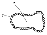
本発明における被膜3は、図2に示す例のように、たとえば不定形(球形に近い場合もある)蛍光体粒子2の表面に金属酸化物の子粒子を付着させ、膜状に形成される。また、図3は、本発明における被膜3’を有する蛍光体粒子2の好ましい他の例を模式的に示す断面図であるが、図3に示す例のように、子粒子の形がある程度保持された状態で金属酸化物を付着させて被膜3’が形成されるように実現されてもよい。なお、被膜3,3’は、蛍光体粒子2の表面全面を覆ってなることが好ましいが、本発明の効果を阻害しない範囲であれば、蛍光体粒子2の表面の一部(好ましくは全表面の80%以下)が露出していてもよい。
As shown in the example shown in FIG. 2, the
本発明における被膜3,3’の厚みは、特に制限されるものではないが、0.05〜3μmの範囲内であることが好ましく、0.1〜1μmの範囲内であることがより好ましい。被膜3,3’の厚みが0.05μm未満である場合には、上述した分散性向上の効果が得られにくい傾向にあり、また、被膜3,3’の厚みが3μmを超えると、発光効率の低下を招く虞があるためである。なお、被膜3,3’の厚みは、次のようにして測定された値を指す。蛍光体粒子を樹脂中に分散させた後に硬化し、アルゴンイオンビームで研磨して蛍光体の断面を露出させる。この断面をSEM(走査型電子顕微鏡)とEDX(エネルギー分散型X線元素分析装置)を用いて元素分析を行い、得られた元素のマッピング画像から蛍光体粒子を覆っている平均的な厚みを算出する。
The thickness of the
本発明の波長変換部材1において、上述した被膜3で覆われた蛍光体粒子2を分散させる媒体4としては、たとえばシリコーン樹脂、エポキシ樹脂などの樹脂材料、およびガラス材料などの当分野において従来より広く用いられている適宜の材料を特に制限なく用いることができるが、樹脂材料、中でも特にシリコーン樹脂にて媒体4が形成されてなることが好ましい。シリコーン樹脂は、骨格としてシロキサン結合(Si−O)を有しているため、蛍光体の励起光として用いられる青色から近紫外の光によって劣化しにくいためである。
In the
本発明の波長変換部材1において、媒体4中に分散させる被膜3で覆われた蛍光体粒子2の量は特に制限されるものではないが、2〜25重量%の範囲内であることが好ましく、5〜20重量%の範囲内であることがより好ましい。媒体4中に分散された蛍光体粒子2の量が2重量%未満である場合には、発光強度が低下する傾向にあり、また、媒体4中に分散された蛍光体粒子2の量が25重量%を超える場合にも、発光強度が低下する傾向にあるためである。
In the
本発明の波長変換部材は、複数種の蛍光体粒子が1つの媒体中に分散されてなる構成で実現されてもよい。好適には、蛍光のピーク波長が400〜500nmの第1の蛍光体粒子と、蛍光のピーク波長が500〜600nmの第2の蛍光体粒子と、蛍光のピーク波長が600〜700nmの第3の蛍光体粒子とが、いずれも上述したように被膜で覆われた状態で、媒体中に分散されてなる構造の波長変換部材が例示される。この場合、第1の蛍光体粒子、第2の蛍光体粒子および第3の蛍光体粒子をそれぞれ覆う被膜は、それぞれ上述した中で別の材料からなっていてもよく、同じ材料からなっていてもよい。このように複数種の蛍光体粒子を1つの媒体中に分散させた構成で波長変換部材を実現する場合、各蛍光体粒子は、その合計量が上述した範囲内となるように媒体中に分散されてなることが好ましい。 The wavelength conversion member of the present invention may be realized by a configuration in which a plurality of types of phosphor particles are dispersed in one medium. Preferably, a first phosphor particle having a fluorescence peak wavelength of 400 to 500 nm, a second phosphor particle having a fluorescence peak wavelength of 500 to 600 nm, and a third phosphor particle having a fluorescence peak wavelength of 600 to 700 nm. A wavelength conversion member having a structure in which phosphor particles are dispersed in a medium in a state where all the phosphor particles are covered with a film as described above is exemplified. In this case, the coating covering each of the first phosphor particles, the second phosphor particles, and the third phosphor particles may be made of different materials as described above, or may be made of the same material. Also good. When a wavelength conversion member is realized with a configuration in which a plurality of types of phosphor particles are dispersed in one medium as described above, each phosphor particle is dispersed in the medium so that the total amount thereof is within the above-described range. It is preferable to be made.
ここで、蛍光のピーク波長が400〜500nmの第1の蛍光体粒子としては、上述した酸窒化物または窒化物の蛍光体粒子のうち、たとえばCeを賦活したJEM蛍光体(組成式:La1-xAl(Si6-z,Alz)N10-zOz:Ce3+ xなど)などの青色蛍光体粒子が例示される。また蛍光のピーク波長が500〜600nmの第2の蛍光体粒子としては、上述した酸窒化物または窒化物の蛍光体粒子のうち、たとえばEuを賦活したβサイアロンからなる蛍光体(組成式:Si3-zAlzN4-zOz:Eu2+など)などの緑色蛍光体粒子が例示される。さらに、蛍光のピーク波長が600〜700nmの第3の蛍光体粒子としては、上述した酸窒化物または窒化物の蛍光体粒子のうち、たとえばEuを賦活したCaAlSiN3:Eu2+などの組成の赤色蛍光体粒子が例示される。ここで、各蛍光体粒子の蛍光のピーク波長は、たとえば分光蛍光光度計F−4500(日立製作所製)を用いて測定された値を指す。 Here, as the first phosphor particles having a fluorescence peak wavelength of 400 to 500 nm, among the above-described oxynitride or nitride phosphor particles, for example, a JEM phosphor activated with Ce (composition formula: La 1 -x Al (Si 6-z, Al z) N 10-z O z: such as Ce 3+ x) blue phosphor particles, such as are exemplified. As the second phosphor particles having a fluorescence peak wavelength of 500 to 600 nm, among the above-described oxynitride or nitride phosphor particles, for example, a phosphor made of β-sialon activated Eu (composition formula: Si 3-z Al z N 4- z O z: etc. Eu 2+) green phosphor particles, such as are exemplified. Furthermore, as the third phosphor particles having a fluorescence peak wavelength of 600 to 700 nm, among the oxynitride or nitride phosphor particles described above, for example, a composition such as CaAlSiN 3 : Eu 2+ activated Eu is used. Red phosphor particles are exemplified. Here, the peak wavelength of fluorescence of each phosphor particle indicates a value measured using, for example, a spectrofluorometer F-4500 (manufactured by Hitachi, Ltd.).
本発明の波長変換部材はまた、複数個の波長変換部材に、それぞれ異なる種類の蛍光体粒子が分散されてなる構成で実現されてもよい。好適には、蛍光のピーク波長が400〜500nmの蛍光体粒子(上述した第1の蛍光体粒子)が前記媒体に分散された第1の波長変換部材と、蛍光のピーク波長が500〜600nmの蛍光体粒子(上述した第2の蛍光体粒子)が前記媒体に分散された第2の波長変換部材と、蛍光のピーク波長が600〜700nmの蛍光体粒子(上述した第3の蛍光体粒子)が前記媒体に分散された第3の波長変換部材とを備える構造の波長変換部材が例示される。この場合、第1の波長変換部材、第2の波長変換部材および第3の波長変換部材において蛍光体をそれぞれ覆う被膜および媒体は、それぞれ上述した中で別の材料からなっていてもよく、同じ材料からなっていてもよい。第1の波長変換部材、第2の波長変換部材および第3の波長変換部材にそれぞれ分散される第1の蛍光体、第2の蛍光体および第3の蛍光体としては、上述したのと同じものを用いることができる。 The wavelength conversion member of the present invention may also be realized by a configuration in which different types of phosphor particles are dispersed in a plurality of wavelength conversion members. Preferably, a first wavelength conversion member in which phosphor particles having a fluorescence peak wavelength of 400 to 500 nm (the first phosphor particles described above) are dispersed in the medium, and a fluorescence peak wavelength of 500 to 600 nm A second wavelength conversion member in which phosphor particles (second phosphor particles described above) are dispersed in the medium, and phosphor particles having a fluorescence peak wavelength of 600 to 700 nm (third phosphor particles described above). Is exemplified by a wavelength conversion member having a structure including a third wavelength conversion member dispersed in the medium. In this case, the film and the medium covering the phosphor in the first wavelength conversion member, the second wavelength conversion member, and the third wavelength conversion member may be made of different materials as described above, and are the same. It may consist of materials. The first phosphor, the second phosphor, and the third phosphor dispersed in the first wavelength conversion member, the second wavelength conversion member, and the third wavelength conversion member, respectively, are the same as described above. Things can be used.
本発明の波長変換部材は、その形状については特に制限されるものではないが、シート状物に形成されることが好ましい。上述したように本発明の波長変換部材が複数個の波長変換部材(たとえば第1〜第3の波長変換部材)から構成される場合には、複数層のシート状物に形成できる。また後述するように、半導体発光素子と組み合わせて一体化した発光装置を実現する場合には、半導体発光素子、電極(半導体発光素子が電気的に接続される)およびミラーがこれらに囲まれた空間を形成するように予め設けられた基材上に、上記空間を充填するようにして単層または複数層の波長変換部材を形成するようにしてもよい。また、波長変換部材は、その厚みについては特に制限されるものではない。 The wavelength conversion member of the present invention is not particularly limited as to its shape, but is preferably formed into a sheet-like material. As described above, when the wavelength conversion member of the present invention is composed of a plurality of wavelength conversion members (for example, first to third wavelength conversion members), it can be formed into a sheet of multiple layers. As will be described later, when a light emitting device integrated with a semiconductor light emitting element is realized, a space in which the semiconductor light emitting element, the electrode (the semiconductor light emitting element is electrically connected), and the mirror are surrounded by them. A single-layer or multiple-layer wavelength conversion member may be formed on a base material provided in advance so as to fill the space. Further, the thickness of the wavelength conversion member is not particularly limited.
図4は、本発明の好ましい一例の発光装置21を模式的に示す断面図である。本発明は、半導体発光素子を備え、当該半導体発光素子が発する光が入射するように配置された、上述した本発明の波長変換部材とを備える発光装置についても提供する。このような本発明の発光装置21では、上述したように蛍光体粒子の媒体への分散性が向上された波長変換部材1を備えることによって、優れた波長変換効率を有する。
FIG. 4 is a cross-sectional view schematically showing a
図4には、上述した、蛍光のピーク波長が400〜500nmの第1の蛍光体粒子23と、蛍光のピーク波長が500〜600nmの第2の蛍光体粒子24と、蛍光のピーク波長が600〜700nmの第3の蛍光体粒子25とが、いずれも上述したように被膜26,27,28で覆われた状態で、媒体29中に分散されてなる構造の波長変換部材22を備える例の発光装置21が示されている。本発明の発光装置21は、半導体発光素子30を備え、上述した波長変換部材22は、当該半導体発光素子30が発する光が入射するよに配置される(図4に示す例では、半導体発光素子30は波長変換部材22に封止されてなる。)。また、図4に示す発光装置21は、基体31と、基体31の表面に形成された電極32,33と、ミラー34とを備え、半導体発光素子30は電極32,33に電気的に接続されてなる。
In FIG. 4, the above-described first
このような本発明の発光装置21によれば、波長変換部材にそれぞれ被膜が形成された3種類の蛍光体粒子を配合してなることによって、概ね白色を呈する(色度座標x=0.32〜0.34、色度座標y=0.32〜0.34)発光装置を実現することができる。またこのような本発明の発光装置21によれば、色の三原色を発光することができ、また各蛍光体の発光スペクトルの半値幅がたとえば50nm以上と広いため、良好な演色性を有する発光装置を実現することができる。
According to the
また図5は、本発明の好ましい他の例の発光装置41を模式的に示す断面図である。図5に示す例の発光装置41では、上述した、蛍光のピーク波長が400〜500nmの蛍光体粒子(第1の蛍光体粒子)45が媒体51に分散された第1の波長変換部材42と、蛍光のピーク波長が500〜600nmの蛍光体粒子(第2の蛍光体粒子)46が媒体52に分散された第2の波長変換部材43と、蛍光のピーク波長が600〜700nmの蛍光体粒子(第3の蛍光体粒子)47が媒体53に分散された第3の波長変換部材44とを備える波長変換部材を用いた場合を示している。なお、図4に示した例と同様、第1〜第3の蛍光体粒子45,46,47は、それぞれ当該蛍光体粒子よりも大きな誘電率を有する被膜48,49,50で覆われている。図5に示す例では、半導体発光素子30側から、第3の波長変換部材44、第2波長変換部材43、第1の波長変換部材42が順に積層されてなる。なお、図5に示す例の発光装置41は、このような波長変換部材を用いたこと以外は、図4に示した例の発光装置21と同様の構成を有しており、同様の構成を有する部分には同一の参照符を付して説明を省略する。
FIG. 5 is a cross-sectional view schematically showing a
図5に示す例の発光装置41では、半導体発光装置30から発せられた励起光は、第3の波長変換部材44、第2の波長変換部材43、第1の波長変換部材42でそれぞれ各色に変換される。この際、半導体発光素子30が発する光が、第3の波長変換部材44、第2の波長変換部材43、第1の波長変換部材42の順に入射するように構成されてなることによって、蛍光のピーク波長が600〜700nmの第3の蛍光体粒子47を含む第3の波長変換部材44で発光した光は、その上の蛍光のピーク波長が500〜600nmの第2の蛍光体粒子46を含む第2の波長変換部材43および蛍光のピーク波長が400〜500nmの第1の蛍光体粒子45を含む第1の波長変換部材42で吸収されにくい。また、蛍光のピーク波長が500〜600nmの第2の蛍光体粒子46を含む第2の波長変換部材43で発光した光は、その上の蛍光のピーク波長が400〜500nmの第1の蛍光体粒子45を含む第1の波長変換部材42で吸収されにくい。これは、一般に蛍光体が、その蛍光を発する波長における光吸収率と比べて、蛍光の波長よりも長波長域における光吸収率が小さいことに起因する(特許文献6を参照)。このため、図5に示す例の発光装置41では、各波長変換部材による光吸収を低減して、可視光を効率良く発光させることができる。
In the
さらに、本発明の発光装置41では、第1〜第3の蛍光体粒子45,46,47がそれぞれ被膜48,49,50で覆われているため、蛍光体粒子の表面における光の反射が少なく、その結果として蛍光の再吸収が多くなるため、上述したこのような配置にすることによる再吸収を低減するメリットが大きくなる。これにより、色の三原色を発光することができ、また各蛍光体粒子の発光スペクトルの半値幅が、酸窒化物蛍光体および窒化物蛍光体の場合は、たとえば50nm以上と広いため、演色性が良好である発光装置を実現することができる。
Furthermore, in the
また図6は、本発明のさらに好ましい他の例の発光装置61を模式的に示す断面図である。図6に示す例の発光装置61は、半導体発光素子30が発する光が、第2の波長変換部材43、第3の波長変換部材44、第1の波長変換部材42の順に入射されるように構成されてなること以外は、図5に示した例の発光装置41と同様であり、同様の構成を有する部分については同一の参照符を付して説明を省略している。図6に示す例の発光装置61は、半導体発光素子30側から、蛍光のピーク波長が500〜600nmの蛍光体粒子(第2の蛍光体粒子)46が媒体52に分散された第2の波長変換部材43、蛍光のピーク波長が600〜700nmの蛍光体粒子(第3の蛍光体粒子)47が媒体53に分散された第3の波長変換部材44、ならびに、蛍光のピーク波長が400〜500nmの蛍光体粒子(第1の蛍光体粒子)45が媒体51に分散された第1の波長変換部材42が順次積層された構造を備えている。
FIG. 6 is a cross-sectional view schematically showing another preferred example of the
本発明では、図6に示すように第1〜第3の波長変換部材42,43,44を配置した場合であっても、視感度が低く発光効率も他の色に比べて若干劣る蛍光のピーク波長が400〜500nmの第1の蛍光体粒子45を半導体発光素子30から離れた位置に配置していることにより、蛍光のピーク波長が500〜600nmの第2の蛍光体粒子46を含む第2の波長変換部材43および蛍光のピーク波長が600〜700nmの第3の蛍光体粒子47における第1の蛍光体粒子45からの蛍光の再吸収を抑制することができる。このように、励起光の吸収が多い蛍光のピーク波長が400〜500nmの第1の蛍光体粒子45を含む第1の波長変換部材42を最上層とすることによって、第2の蛍光体粒子46からのピーク波長が500〜600nmの蛍光および第3の蛍光体粒子47からのピーク波長が600〜700nmの蛍光を効率よく取り出すことができ、全体として波長変換効率に優れた白色の発光装置を実現することができる。また、このような発光装置61においても、色の三原色を発光することができ、また各蛍光体の発光スペクトルの半値幅がたとえば50nm以上と広いため、演色性が良好である。
In the present invention, even when the first to third
本発明の発光装置21,41,61に用いられる半導体発光素子30は、当分野において従来より広く用いられている適宜のものを用いることができ、特に制限されるものではないが、良好な光電変換効率を有することから、発光ピーク波長が370〜480nmの範囲内のものを用いることが好ましく、発光ピーク波長が390〜420nmの範囲内(紫色から近紫外)のものを用いることがより好ましい。このような半導体発光素子30は、GaN系半導体(少なくともGaとNを含み、必要に応じてAl、Inおよびn型ドーパント、p型ドーパントなどを用いた半導体)を用いることが好ましく、特に好適な例としては発光ピーク波長が405nmのGaN系半導体よりなるLEDが例示される。
As the semiconductor
また本発明における半導体発光素子30として、青色光源(波長ピーク波長420〜480nm、たとえば460nm程度のもの)を用いても勿論よい。この場合、青色蛍光体粒子を持ちなくとも、青色および白色を呈する発光装置を実現できるという利点がある。また、現在の技術では、青色蛍光体の効率は他の蛍光体(赤色蛍光体、緑色蛍光体など)と比較すると若干劣るが、青色光源を用いることで、全体としての発光効率を増大させることができるという利点もある。
Of course, a blue light source (having a wavelength peak wavelength of 420 to 480 nm, for example, about 460 nm) may be used as the semiconductor
また、半導体発光素子30としては、GaN系半導体よりなる半導体発光素子以外に有機半導体や酸化亜鉛半導体などよりなる半導体発光素子を用いてもよく、また半導体レーザを用いてもよい。
Further, as the semiconductor
本発明の波長変換部材および発光装置を製造する方法については特に制限されるものではなく、当分野において従来より広く行われている適宜の方法によって製造することが可能である。たとえば、まず、蛍光体粒子に被膜形成材料の子粒子を付着させて、蛍光体粒子を覆う被膜を形成する。次に、被膜を形成した蛍光体粒子と媒体の形成材料(たとえば液状のシリコーン樹脂)中に添加し、均一に混合した後、所定時間加熱(たとえば媒体をシリコーン樹脂で形成する場合には120℃で60分間加熱)して、媒体の形成材料を硬化させて媒体を形成する。図1に示した例のような波長変換部材1を作製する場合には、従来公知の適宜の方法を用いて、硬化後の媒体がシート状物となるように成形すればよい。また、図4〜図6に示した例のような発光装置に用いる場合には、たとえば半導体発光素子30、電極32,33およびミラー34に設けた基材31上にこれらによって形成された空間を充填するようにして被膜が形成された蛍光体粒子を均一に混合させた媒体の形成材料を注入して、波長変換部材を作製する。この際、図5および図6に示したように第1〜第3の波長変換部材を作製する場合には、順次、各波長変換部材を作製するようにすればよい。また、図4に示したように、媒体中にそれぞれ被膜で覆われた第1〜第3の蛍光体粒子を分散させた波長変換部材を形成する場合には、それぞれ被膜で覆われた第1〜第3の蛍光体粒子を媒体の形成材料に添加して均一に混合後、1つの波長変換部材を作製するようにすればよい。
The method for producing the wavelength conversion member and the light-emitting device of the present invention is not particularly limited, and can be produced by an appropriate method widely used in the art. For example, first, the child particles of the film forming material are attached to the phosphor particles to form a film covering the phosphor particles. Next, the phosphor particles on which the film is formed and the medium forming material (for example, liquid silicone resin) are added and mixed uniformly, and then heated for a predetermined time (for example, 120 ° C. when the medium is formed of silicone resin). For 60 minutes) to cure the medium forming material and form the medium. When the
以下、実施例および比較例を挙げて本発明をより詳細に説明するが、本発明はこれらに限定されるものではない。 EXAMPLES Hereinafter, although an Example and a comparative example are given and this invention is demonstrated in detail, this invention is not limited to these.
<実施例1>
図2に示したように不定形を有するEuを賦活したβサイアロン蛍光体(組成式:Si3-zAlzN4-zOz:Eu2+)である緑色蛍光体粒子2に、酸化マグネシウムの子粒子を付着させて、被膜3で覆った。被膜3の厚みは、酸化マグネシウムの重量比が0.1の場合に、0.5μm程度であった。次に、上述の被膜3を形成した緑色蛍光体粒子2をシリコーン樹脂/蛍光体粒子の重量比が100g/10gの割合で、液体状のシリコーン樹脂に添加して均一に混合した後、厚み0.5mmのシート状物に成形し、120℃、60分間の加熱によって硬化させて、図1に示した波長変換部材1を作製した。
<Example 1>
As shown in FIG. 2, β-sialon phosphor activated by Eu having an irregular shape (composition formula: Si 3 -z Al z N 4 -z O z : Eu 2+ ) is oxidized into
<比較例1>
被膜を形成しなかったこと以外は実施例1と同様にして、波長変換部材を形成した。
<Comparative Example 1>
A wavelength conversion member was formed in the same manner as in Example 1 except that no film was formed.
<評価>
実施例1および比較例1でそれぞれ作製された波長変換部材について、分散性の評価を以下のようにして行った。β−サイアロン蛍光体および酸化マグネシウムをコーティングしたβ−サイアロン蛍光体を、それぞれ0.5gずつとり、それぞれシリコーン樹脂5gに均一に分散させてガラス管に入れ、沈降試験を行った。均一に分散させた状態から48時間放置した後、分離した上澄み液の高さを比較した。β−サイアロン蛍光体の上澄み液の高さが2mmであったのに対して、酸化マグネシウムをコーティングしたα−サイアロンの上澄み液の高さは殆ど0mmであった。このことから、酸化マグネシウムをコーティングすることにより、分散性は向上したものと考えられる。
<Evaluation>
About the wavelength conversion member produced in Example 1 and Comparative Example 1, the dispersibility was evaluated as follows. 0.5-g each of β-sialon phosphor and β-sialon phosphor coated with magnesium oxide were each uniformly dispersed in 5 g of silicone resin and placed in a glass tube, and a sedimentation test was performed. After leaving for 48 hours from the uniformly dispersed state, the heights of the separated supernatants were compared. The height of the supernatant of the β-sialon phosphor was 2 mm, whereas the height of the supernatant of α-sialon coated with magnesium oxide was almost 0 mm. From this, it is considered that the dispersibility is improved by coating with magnesium oxide.
また、β−サイアロン蛍光体および酸化マグネシウムをコーティングしたβ−サイアロン蛍光体を、それぞれ0.1gずつとり、それぞれエタノール10gに分散させてゼータ電位を測定した(電気泳動法によるゼータ電位測定装置を使用)。比較例1では25mVであったのに対して、実施例1では60mVと大きくなっており、被膜を形成したことで蛍光体粒子の媒体への分散性が向上されていたことが分かった。これは、実施例1では、誘電率が7.5である緑色蛍光体粒子2を覆って誘電率が9である酸化マグネシウムを用いて被膜3を形成したことに起因するものと考えられる。
Further, 0.1 g each of β-sialon phosphor and β-sialon phosphor coated with magnesium oxide were taken and dispersed in 10 g of ethanol, respectively, and zeta potential was measured (using a zeta potential measuring device by electrophoresis method). ). While it was 25 mV in Comparative Example 1 and increased to 60 mV in Example 1, it was found that the dispersibility of the phosphor particles in the medium was improved by forming the coating. This is presumably because, in Example 1, the
<実施例2>
図4に示した例の発光装置21を作製した。第1の蛍光体粒子23としてCeを賦活したJEM蛍光体(組成式:La1-xAl(Si6-z,Alz)N10-zOz:Ce3+ x)である青色蛍光体粒子(誘電率:7.5、屈折率:2.0、蛍光のピーク波長:490nm)、第2の蛍光体粒子24としてEuを賦活したβサイアロン蛍光体(組成式:Si3-zAlzN4-zOz:Eu2+)である緑色蛍光体粒子(誘電率:7.5、屈折率:2.0、蛍光のピーク波長:540nm)、第3の蛍光体粒子25としてEuを賦活したCaAlSiN3からなる赤色蛍光体粒子(誘電率:7.5、屈折率:2.0、蛍光のピーク波長:660nm)を用い、これらの第1〜第3の蛍光体粒子23,24,25をそれぞれ酸化マグネシウム(誘電率:9.0、屈折率:1.74)で覆って被膜26,27,28を形成した。これらをシリコーン樹脂/合計の蛍光体粒子の重量比が100g/15gとなるように、それぞれの蛍光体を液体状のシリコーン樹脂(硬化時の屈折率:1.4)に添加して均一に混合した後、基体31上に注入し、120℃、60分間の加熱によって硬化させた。このようにして、媒体29中にそれぞれ被膜26,27,28が形成された第1〜第3の蛍光体粒子23,24,25が分散されてなる波長変換部材22を形成した。
<Example 2>
The
なお、基体31には、電極32,33、当該電極32,33に電気的に接続された半導体発光素子30、ならびにミラー34が予め形成されており、媒体29中に半導体発光素子30が封止されるように、上記波長変換部材22を形成した。半導体発光素子30としては、発光ピーク波長が405nmのGaN系半導体(少なくともGaとNを含み、必要に応じてAl、Inおよびn型ドーパント、p型ドーパントなどを用いた半導体)よりなるLEDを用いた。
The
このようにして作製された図4に示した例の発光装置21において、第1〜第3の蛍光体粒子23,24,25は、これら蛍光体粒子よりも誘電率が大きい酸化マグネシウムで形成された被膜26,27,28で覆われているため、媒体29中における分散性が向上されている。また、波長変換部材22における媒体29の形成材料であるシリコーン樹脂と、第1〜第3の蛍光体粒子23,24,25の間の屈折率を有する酸化マグネシウムにて被膜26,27,28を形成したことによって、第1〜第3の蛍光体粒子23,24,25への励起光の入射効率および第1〜第3の蛍光体粒子23,24,25からの蛍光の取り出し効率を図ることができた。このような発光装置21は、3種類の蛍光体粒子を配合することにより、ほぼ白色である色度座標x=0.32、色度座標y=0.35の色の発光を得ることができた。また、色の三原色を発光することができ、また各蛍光体粒子の発光スペクトルの半値幅がたとえば50nm以上と広いため、演色性が良好であった。このように、酸窒化物または窒化物で形成された蛍光体粒子と、前記蛍光体粒子を覆い蛍光体粒子よりも大きな誘電率を有する被膜と、前記被膜で覆われた蛍光体粒子を分散させた媒体とを備える波長変換部材を半導体発光素子と組み合わせることで、小型で白色を呈する高出力の発光装置が得られた。
In the
<実施例3>
図5に示した例の発光装置41を作製した。第1〜第3の蛍光体粒子45,46,47および被膜48,49,50としては、実施例2で上述した第1〜第3の蛍光体粒子23,24,25および被膜26,27,28と同様のものを用いた。
<Example 3>
The
まず、被膜50で覆われた第3の蛍光体粒子47(赤色蛍光体粒子)を、シリコーン樹脂/蛍光体粒子の重量比が100g/0.5gとなるように、液状のシリコーン樹脂中に均一に混合し、基体31上に注入した後、120℃、60分間の加熱によって硬化させて、第3の波長変換部材44を形成した(厚み:0.5mm)。基体31には、電極32,33、当該電極32,33に電気的に接続された半導体発光素子30、ならびにミラー34が予め形成されており、媒体29中に半導体発光素子30が封止されるように、上記第3の波長変換部材44を形成した。半導体発光素子30としては、発光ピーク波長が405nmのGaN系半導体よりなるLEDを用いた。
First, the third phosphor particles 47 (red phosphor particles) covered with the
次に、被膜49で覆われた第2の蛍光体粒子46(緑色蛍光体粒子)を、シリコーン樹脂/蛍光体粒子の重量比が100g/1.4gとなるように、液状のシリコーン樹脂中に均一に混合し、第3の波長変換部材44上に重ねるように注入し、120℃、60分間の加熱によって硬化させて、第2の波長変換部材43を形成した(厚み:0.5mm)。
Next, the second phosphor particles 46 (green phosphor particles) covered with the
最後に、被膜48で覆われた第1の蛍光体粒子45(青色蛍光体粒子)を、シリコーン樹脂/蛍光体粒子の重量比が100g/13.1gとなるように、液状のシリコーン樹脂中に均一に混合し、第2の波長変換部材43上に重ねるように注入し、120℃、60分間の加熱によって硬化させて、第1の波長変換部材42を形成した(厚み:0.5mm)。
Finally, the first phosphor particles 45 (blue phosphor particles) covered with the
このようにして、図5に示したように、半導体発光素子30が発する光が、第3の波長変換部材44、第2の波長変換部材43、第1の波長変換部材42の順に入射するように構成されてなる発光装置41を作製した。このような発光装置41では、半導体発光装置30から発せられた励起光は、第3の波長変換部材44、第2の波長変換部材43、第1の波長変換部材42でそれぞれ各色に変換される。この際、第3の蛍光体粒子47として赤色蛍光体粒子を含む第3の波長変換部材44で発光した光は、その上の第2の蛍光体粒子46として緑色蛍光体粒子を含む第2の波長変換部材43および第1の蛍光体粒子45として青色蛍光体粒子を含む第1の波長変換部材42で吸収されにくい。また、第2の蛍光体粒子46として緑色蛍光体粒子を含む第2の波長変換部材43で発光した光は、その上の第1の蛍光体粒子45として青色蛍光体粒子を含む第1の波長変換部材42で吸収されにくい。このように、各波長変換部材による光吸収を低減して、可視光を効率良く発光させることができる。
Thus, as shown in FIG. 5, the light emitted from the semiconductor
さらに、本発明の発光装置41では、第1〜第3の蛍光体粒子45,46,47がそれぞれ被膜48,49,50で覆われているため、蛍光体粒子の表面における光の反射が少なく、その結果として蛍光の再吸収が多くなるため、上述したこのような配置にすることによる再吸収を低減するメリットが大きくなる。これにより、色の三原色を発光することができ、また各蛍光体粒子の発光スペクトルの半値幅が、酸窒化物蛍光体および窒化物蛍光体の場合は、たとえば50nm以上と広いため、演色性が良好である発光装置を実現することができる。
Furthermore, in the
<実施例4>
第3の波長変換部材44と第2の変換部材43の形成順序を逆にしたこと以外は実施例3と同様にして、図6に示した例の発光装置61を作製した。このようにして得られた発光装置61は、半導体発光素子30が発する光が、第2の波長変換部材43、第3の波長変換部材44、第1の波長変換部材42の順に入射するように構成されてなる。この配置によっても、視感度が低く発光効率も他の色に比べて若干劣る第1の蛍光体粒子45としての青色蛍光体粒子を半導体発光素子30から離れた位置に配置することによって、第2の蛍光体粒子46として緑色蛍光体粒子を含む第2の波長変換部材43および第3の蛍光体粒子47として赤色蛍光体粒子を含む第3の波長変換部材44における青色の蛍光の再吸収を抑制することができる。
<Example 4>
A
したがって、このような実施例4で作製した発光装置61であっても、青色蛍光体を含む第1の波長変換部材42を最上層とすることによって、緑色および赤色を効率よく取り出すことができ、全体として波長変換効率に優れた白色の発光装置が得られた。これにより、色の三原色を発光することができ、また各蛍光体の発光スペクトルの半値幅がたとえば50nm以上と広いため、演色性が良好であった。
Therefore, even in the
今回開示された実施の形態、実施例および比較例はすべての点で例示であって制限的なものではないと考えられるべきである。本発明の範囲は上記した説明ではなくて特許請求の範囲によって示され、特許請求の範囲と均等の意味および範囲内でのすべての変更が含まれることが意図される。 The embodiments, examples, and comparative examples disclosed this time should be considered as illustrative in all points and not restrictive. The scope of the present invention is defined by the terms of the claims, rather than the description above, and is intended to include any modifications within the scope and meaning equivalent to the terms of the claims.
1 波長変換部材、2 蛍光体粒子、3,3’ 被膜、4 媒体、21,41,61 発光装置、22 波長変換部材、23,45 第1の蛍光体粒子、24,46 第2の蛍光体粒子、25,47 第3の蛍光体粒子、26,27,28,48,49,50 被膜、29,51,52,53 媒体、30 半導体発光素子、31,32 電極、34 ミラー、42 第1の波長変換部材、43 第2の波長変換部材、44 第3の波長変換部材。
DESCRIPTION OF
Claims (16)
Priority Applications (1)
| Application Number | Priority Date | Filing Date | Title |
|---|---|---|---|
| JP2006341112A JP2008150518A (en) | 2006-12-19 | 2006-12-19 | Wavelength conversion member and light emitting device |
Applications Claiming Priority (1)
| Application Number | Priority Date | Filing Date | Title |
|---|---|---|---|
| JP2006341112A JP2008150518A (en) | 2006-12-19 | 2006-12-19 | Wavelength conversion member and light emitting device |
Publications (1)
| Publication Number | Publication Date |
|---|---|
| JP2008150518A true JP2008150518A (en) | 2008-07-03 |
Family
ID=39653042
Family Applications (1)
| Application Number | Title | Priority Date | Filing Date |
|---|---|---|---|
| JP2006341112A Pending JP2008150518A (en) | 2006-12-19 | 2006-12-19 | Wavelength conversion member and light emitting device |
Country Status (1)
| Country | Link |
|---|---|
| JP (1) | JP2008150518A (en) |
Cited By (19)
| Publication number | Priority date | Publication date | Assignee | Title |
|---|---|---|---|---|
| EP2134133A1 (en) | 2008-06-09 | 2009-12-16 | Nec Corporation | Wireless communication system, base station, scheduling method, and program |
| JP2010045328A (en) * | 2008-07-18 | 2010-02-25 | Sharp Corp | Light-emitting device and method of manufacturing the same |
| JP2010100827A (en) * | 2008-09-25 | 2010-05-06 | Panasonic Electric Works Co Ltd | Wavelength conversion member and light-emitting device using the same |
| JP2011243369A (en) * | 2010-05-17 | 2011-12-01 | Sharp Corp | Light-emitting device, illumination device, and vehicle headlight |
| KR20120081939A (en) * | 2009-11-17 | 2012-07-20 | 크리, 인코포레이티드 | Luminescent particles, methods of identifying same and light emitting devices including the same |
| JP2013001792A (en) * | 2011-06-16 | 2013-01-07 | Toray Ind Inc | Fluorescent substance-containing sheet, led emitter using the same and method for producing the same |
| JP2013153082A (en) * | 2012-01-25 | 2013-08-08 | Sharp Corp | Light-emitting diode module, and manufacturing method of light-emitting diode module |
| US8733996B2 (en) | 2010-05-17 | 2014-05-27 | Sharp Kabushiki Kaisha | Light emitting device, illuminating device, and vehicle headlamp |
| US8833991B2 (en) | 2010-02-10 | 2014-09-16 | Sharp Kabushiki Kaisha | Light emitting device, with light guide member having smaller exit section, and illuminating device, and vehicle headlight including the same |
| JP2014175498A (en) * | 2013-03-08 | 2014-09-22 | Sharp Corp | Light-emitting apparatus |
| US8876344B2 (en) | 2009-12-17 | 2014-11-04 | Sharp Kabushiki Kaisha | Vehicle headlamp with excitation light source, light emitting part and light projection section |
| JP2015089898A (en) * | 2013-11-05 | 2015-05-11 | 信越化学工業株式会社 | Inorganic phosphor powder, curable resin composition using inorganic phosphor powder, wavelength conversion member, and optical semiconductor device |
| US9816677B2 (en) | 2010-10-29 | 2017-11-14 | Sharp Kabushiki Kaisha | Light emitting device, vehicle headlamp, illumination device, and laser element |
| WO2018159268A1 (en) * | 2017-03-02 | 2018-09-07 | パナソニックIpマネジメント株式会社 | Wavelength conversion member, light source and lighting device |
| WO2019065194A1 (en) * | 2017-09-28 | 2019-04-04 | パナソニックIpマネジメント株式会社 | Wavelength conversion member, light source, fluorescent body particles, and production method for wavelength conversion member |
| WO2019065193A1 (en) * | 2017-09-28 | 2019-04-04 | パナソニックIpマネジメント株式会社 | Wavelength conversion member and light source |
| JP2020066599A (en) * | 2018-10-25 | 2020-04-30 | ロート製薬株式会社 | Composite powder, external composition for skin, and method for enhancing fluorescence intensity of inorganic fluorescent powder |
| WO2021199971A1 (en) * | 2020-04-02 | 2021-10-07 | ソニーグループ株式会社 | Wavelength conversion member, light source device, and projector |
| CN117182767A (en) * | 2022-12-30 | 2023-12-08 | 衢州学院 | Polishing abrasive particles, polishing equipment and polishing methods based on traveling wave dielectrophoresis effect |
Citations (12)
| Publication number | Priority date | Publication date | Assignee | Title |
|---|---|---|---|---|
| JP2002069442A (en) * | 2000-09-01 | 2002-03-08 | Showa Denko Kk | Silica film coated with light emitting grain |
| JP2002097464A (en) * | 1998-07-08 | 2002-04-02 | Matsushita Electric Ind Co Ltd | Phosphor ink for plasma display panel |
| JP2003261869A (en) * | 2002-03-11 | 2003-09-19 | Showa Denko Kk | Luminous particles, manufacturing method therefor and use of the luminous particles |
| JP2003286480A (en) * | 2002-03-05 | 2003-10-10 | Agilent Technol Inc | Improved coated fluorescent filler and method of forming the same |
| JP2004071434A (en) * | 2002-08-08 | 2004-03-04 | Konica Minolta Holdings Inc | Plasma display panel |
| JP2004161807A (en) * | 2002-11-08 | 2004-06-10 | Nichia Chem Ind Ltd | Nitride phosphor and light emitting device |
| JP2005082788A (en) * | 2003-09-11 | 2005-03-31 | Nichia Chem Ind Ltd | Light emitting device, phosphor for light emitting element, and method for manufacturing phosphor for light emitting element |
| JP2006232868A (en) * | 2005-02-22 | 2006-09-07 | Sharp Corp | Oxynitride phosphor and semiconductor light emitting device |
| JP2006232949A (en) * | 2005-02-23 | 2006-09-07 | Matsushita Electric Works Ltd | Method for treating phosphor particle, light emitting device, and phosphor particle |
| JP2006265506A (en) * | 2005-02-28 | 2006-10-05 | Denki Kagaku Kogyo Kk | Phosphor, method for producing the same, and light emitting device using the same |
| JP2007126536A (en) * | 2005-11-02 | 2007-05-24 | Sharp Corp | Wavelength conversion member and light emitting device |
| JP2007324475A (en) * | 2006-06-02 | 2007-12-13 | Sharp Corp | Wavelength conversion member and light emitting device |
-
2006
- 2006-12-19 JP JP2006341112A patent/JP2008150518A/en active Pending
Patent Citations (12)
| Publication number | Priority date | Publication date | Assignee | Title |
|---|---|---|---|---|
| JP2002097464A (en) * | 1998-07-08 | 2002-04-02 | Matsushita Electric Ind Co Ltd | Phosphor ink for plasma display panel |
| JP2002069442A (en) * | 2000-09-01 | 2002-03-08 | Showa Denko Kk | Silica film coated with light emitting grain |
| JP2003286480A (en) * | 2002-03-05 | 2003-10-10 | Agilent Technol Inc | Improved coated fluorescent filler and method of forming the same |
| JP2003261869A (en) * | 2002-03-11 | 2003-09-19 | Showa Denko Kk | Luminous particles, manufacturing method therefor and use of the luminous particles |
| JP2004071434A (en) * | 2002-08-08 | 2004-03-04 | Konica Minolta Holdings Inc | Plasma display panel |
| JP2004161807A (en) * | 2002-11-08 | 2004-06-10 | Nichia Chem Ind Ltd | Nitride phosphor and light emitting device |
| JP2005082788A (en) * | 2003-09-11 | 2005-03-31 | Nichia Chem Ind Ltd | Light emitting device, phosphor for light emitting element, and method for manufacturing phosphor for light emitting element |
| JP2006232868A (en) * | 2005-02-22 | 2006-09-07 | Sharp Corp | Oxynitride phosphor and semiconductor light emitting device |
| JP2006232949A (en) * | 2005-02-23 | 2006-09-07 | Matsushita Electric Works Ltd | Method for treating phosphor particle, light emitting device, and phosphor particle |
| JP2006265506A (en) * | 2005-02-28 | 2006-10-05 | Denki Kagaku Kogyo Kk | Phosphor, method for producing the same, and light emitting device using the same |
| JP2007126536A (en) * | 2005-11-02 | 2007-05-24 | Sharp Corp | Wavelength conversion member and light emitting device |
| JP2007324475A (en) * | 2006-06-02 | 2007-12-13 | Sharp Corp | Wavelength conversion member and light emitting device |
Cited By (32)
| Publication number | Priority date | Publication date | Assignee | Title |
|---|---|---|---|---|
| EP2134133A1 (en) | 2008-06-09 | 2009-12-16 | Nec Corporation | Wireless communication system, base station, scheduling method, and program |
| US8427042B2 (en) | 2008-07-18 | 2013-04-23 | Sharp Kabushiki Kaisha | Light-emitting device and method for manufacturing light-emitting device |
| JP2010045328A (en) * | 2008-07-18 | 2010-02-25 | Sharp Corp | Light-emitting device and method of manufacturing the same |
| JP2010100827A (en) * | 2008-09-25 | 2010-05-06 | Panasonic Electric Works Co Ltd | Wavelength conversion member and light-emitting device using the same |
| US9464225B2 (en) | 2008-11-17 | 2016-10-11 | Cree, Inc. | Luminescent particles, methods of identifying same and light emitting devices including the same |
| KR20120081939A (en) * | 2009-11-17 | 2012-07-20 | 크리, 인코포레이티드 | Luminescent particles, methods of identifying same and light emitting devices including the same |
| JP2012533659A (en) * | 2009-11-17 | 2012-12-27 | クリー インコーポレイテッド | Luminescent particles, method for identifying the same, and light emitting device including the same |
| KR101690813B1 (en) | 2009-11-17 | 2016-12-28 | 크리, 인코포레이티드 | Luminescent particles, methods of identifying same and light emitting devices including the same |
| US8876344B2 (en) | 2009-12-17 | 2014-11-04 | Sharp Kabushiki Kaisha | Vehicle headlamp with excitation light source, light emitting part and light projection section |
| US8833991B2 (en) | 2010-02-10 | 2014-09-16 | Sharp Kabushiki Kaisha | Light emitting device, with light guide member having smaller exit section, and illuminating device, and vehicle headlight including the same |
| US8733996B2 (en) | 2010-05-17 | 2014-05-27 | Sharp Kabushiki Kaisha | Light emitting device, illuminating device, and vehicle headlamp |
| JP2011243369A (en) * | 2010-05-17 | 2011-12-01 | Sharp Corp | Light-emitting device, illumination device, and vehicle headlight |
| US10465873B2 (en) | 2010-10-29 | 2019-11-05 | Sharp Kabushiki Kaisha | Light emitting device, vehicle headlamp, illumination device, and laser element |
| US10281102B2 (en) | 2010-10-29 | 2019-05-07 | Sharp Kabushiki Kaisha | Light emitting device, vehicle headlamp, illumination device, and laser element |
| US9816677B2 (en) | 2010-10-29 | 2017-11-14 | Sharp Kabushiki Kaisha | Light emitting device, vehicle headlamp, illumination device, and laser element |
| JP2013001792A (en) * | 2011-06-16 | 2013-01-07 | Toray Ind Inc | Fluorescent substance-containing sheet, led emitter using the same and method for producing the same |
| JP2013153082A (en) * | 2012-01-25 | 2013-08-08 | Sharp Corp | Light-emitting diode module, and manufacturing method of light-emitting diode module |
| JP2014175498A (en) * | 2013-03-08 | 2014-09-22 | Sharp Corp | Light-emitting apparatus |
| JP2015089898A (en) * | 2013-11-05 | 2015-05-11 | 信越化学工業株式会社 | Inorganic phosphor powder, curable resin composition using inorganic phosphor powder, wavelength conversion member, and optical semiconductor device |
| WO2015068338A1 (en) * | 2013-11-05 | 2015-05-14 | 信越化学工業株式会社 | Inorganic phosphor powder, curable resin composition using inorganic phosphor powder, wavelength conversion member, and optical semiconductor device |
| US10794569B2 (en) | 2017-03-02 | 2020-10-06 | Panasonic Intellectual Property Management Co., Ltd. | Wavelength conversion member, light source and lighting device |
| CN110352368A (en) * | 2017-03-02 | 2019-10-18 | 松下知识产权经营株式会社 | Wavelength converting member, light source and lighting device |
| JPWO2018159268A1 (en) * | 2017-03-02 | 2019-12-19 | パナソニックIpマネジメント株式会社 | Wavelength conversion member, light source and lighting device |
| WO2018159268A1 (en) * | 2017-03-02 | 2018-09-07 | パナソニックIpマネジメント株式会社 | Wavelength conversion member, light source and lighting device |
| WO2019065193A1 (en) * | 2017-09-28 | 2019-04-04 | パナソニックIpマネジメント株式会社 | Wavelength conversion member and light source |
| WO2019065194A1 (en) * | 2017-09-28 | 2019-04-04 | パナソニックIpマネジメント株式会社 | Wavelength conversion member, light source, fluorescent body particles, and production method for wavelength conversion member |
| JPWO2019065193A1 (en) * | 2017-09-28 | 2020-11-26 | パナソニックIpマネジメント株式会社 | Wavelength conversion member and light source |
| JP2020066599A (en) * | 2018-10-25 | 2020-04-30 | ロート製薬株式会社 | Composite powder, external composition for skin, and method for enhancing fluorescence intensity of inorganic fluorescent powder |
| JP2023093715A (en) * | 2018-10-25 | 2023-07-04 | ロート製薬株式会社 | Composite powder, composition for external use on skin, and method for enhancing fluorescence intensity of inorganic fluorescent powder |
| JP7602861B2 (en) | 2018-10-25 | 2024-12-19 | ロート製薬株式会社 | Composite powder, skin external application composition, and method for enhancing fluorescence intensity of inorganic fluorescent powder |
| WO2021199971A1 (en) * | 2020-04-02 | 2021-10-07 | ソニーグループ株式会社 | Wavelength conversion member, light source device, and projector |
| CN117182767A (en) * | 2022-12-30 | 2023-12-08 | 衢州学院 | Polishing abrasive particles, polishing equipment and polishing methods based on traveling wave dielectrophoresis effect |
Similar Documents
| Publication | Publication Date | Title |
|---|---|---|
| TWI429731B (en) | Red-emitting fluorinated phosphor activated by tetravalent manganese ions | |
| US8138666B2 (en) | Wavelength conversion member and light-emitting device | |
| JP6625582B2 (en) | Red line emitting phosphor for use in light emitting diode applications | |
| KR101731741B1 (en) | Red line emitting phosphors for use in led applications | |
| US7026755B2 (en) | Deep red phosphor for general illumination applications | |
| CN103857767B (en) | Opto-electronic device and luminescent material | |
| JP2008150518A (en) | Wavelength conversion member and light emitting device | |
| JP5752650B2 (en) | Light emitting device | |
| JP4895574B2 (en) | Wavelength conversion member and light emitting device | |
| JP5042999B2 (en) | Lighting system with luminescent material to compensate for color shortage | |
| US20060208270A1 (en) | Borate phosphor materials for use in lighting applications | |
| JP2009167338A (en) | Wavelength converting member, light emitting device including the same, and phosphor | |
| WO2004066403A2 (en) | White light emitting device based on ultraviolet light emitting diode and phosphor blend | |
| JP2009019163A (en) | Phosphor particle assembly for light emitting device, light emitting device, and backlight device for liquid crystal display | |
| CN101032037A (en) | White leds with tunable cri | |
| JP2012077289A (en) | Light emitting device | |
| JP5326182B2 (en) | Light emitting device, phosphor for light emitting element, and method for manufacturing the same | |
| CN101517035A (en) | Radiation-emitting device | |
| JP5462211B2 (en) | White light emitting device | |
| CN101896575B (en) | Conversion LED | |
| JP2005167138A (en) | White light emitting device | |
| WO2023171254A1 (en) | Light-emitting device | |
| JP2008227550A (en) | LIGHT EMITTING DIODE, ITS MANUFACTURING METHOD, AND WHITE LIGHTING DEVICE | |
| CN101207168A (en) | white light emitting device |
Legal Events
| Date | Code | Title | Description |
|---|---|---|---|
| A621 | Written request for application examination |
Free format text: JAPANESE INTERMEDIATE CODE: A621 Effective date: 20090218 |
|
| A977 | Report on retrieval |
Free format text: JAPANESE INTERMEDIATE CODE: A971007 Effective date: 20111018 |
|
| A131 | Notification of reasons for refusal |
Free format text: JAPANESE INTERMEDIATE CODE: A131 Effective date: 20111025 |
|
| A521 | Request for written amendment filed |
Free format text: JAPANESE INTERMEDIATE CODE: A523 Effective date: 20111222 |
|
| A131 | Notification of reasons for refusal |
Free format text: JAPANESE INTERMEDIATE CODE: A131 Effective date: 20120117 |
|
| A521 | Request for written amendment filed |
Free format text: JAPANESE INTERMEDIATE CODE: A523 Effective date: 20120312 |
|
| A521 | Request for written amendment filed |
Free format text: JAPANESE INTERMEDIATE CODE: A821 Effective date: 20120312 |
|
| A131 | Notification of reasons for refusal |
Free format text: JAPANESE INTERMEDIATE CODE: A131 Effective date: 20121106 |
|
| A02 | Decision of refusal |
Free format text: JAPANESE INTERMEDIATE CODE: A02 Effective date: 20130305 |