JP2008120598A - Print medium rotary transport apparatus and print system - Google Patents
Print medium rotary transport apparatus and print system Download PDFInfo
- Publication number
- JP2008120598A JP2008120598A JP2007290591A JP2007290591A JP2008120598A JP 2008120598 A JP2008120598 A JP 2008120598A JP 2007290591 A JP2007290591 A JP 2007290591A JP 2007290591 A JP2007290591 A JP 2007290591A JP 2008120598 A JP2008120598 A JP 2008120598A
- Authority
- JP
- Japan
- Prior art keywords
- print media
- sheet
- module
- printing
- Prior art date
- Legal status (The legal status is an assumption and is not a legal conclusion. Google has not performed a legal analysis and makes no representation as to the accuracy of the status listed.)
- Granted
Links
- 230000032258 transport Effects 0.000 abstract 8
- 238000011084 recovery Methods 0.000 description 26
- 238000000034 method Methods 0.000 description 5
- 238000011144 upstream manufacturing Methods 0.000 description 5
- 230000000712 assembly Effects 0.000 description 2
- 238000000429 assembly Methods 0.000 description 2
- 230000009977 dual effect Effects 0.000 description 2
- 238000007689 inspection Methods 0.000 description 2
- 230000010354 integration Effects 0.000 description 2
- 238000010586 diagram Methods 0.000 description 1
- 238000011017 operating method Methods 0.000 description 1
Images


Classifications
-
- B—PERFORMING OPERATIONS; TRANSPORTING
- B41—PRINTING; LINING MACHINES; TYPEWRITERS; STAMPS
- B41J—TYPEWRITERS; SELECTIVE PRINTING MECHANISMS, i.e. MECHANISMS PRINTING OTHERWISE THAN FROM A FORME; CORRECTION OF TYPOGRAPHICAL ERRORS
- B41J11/00—Devices or arrangements of selective printing mechanisms, e.g. ink-jet printers or thermal printers, for supporting or handling copy material in sheet or web form
-
- B—PERFORMING OPERATIONS; TRANSPORTING
- B65—CONVEYING; PACKING; STORING; HANDLING THIN OR FILAMENTARY MATERIAL
- B65H—HANDLING THIN OR FILAMENTARY MATERIAL, e.g. SHEETS, WEBS, CABLES
- B65H29/00—Delivering or advancing articles from machines; Advancing articles to or into piles
- B65H29/12—Delivering or advancing articles from machines; Advancing articles to or into piles by means of the nip between two, or between two sets of, moving tapes or bands or rollers
-
- B—PERFORMING OPERATIONS; TRANSPORTING
- B41—PRINTING; LINING MACHINES; TYPEWRITERS; STAMPS
- B41J—TYPEWRITERS; SELECTIVE PRINTING MECHANISMS, i.e. MECHANISMS PRINTING OTHERWISE THAN FROM A FORME; CORRECTION OF TYPOGRAPHICAL ERRORS
- B41J13/00—Devices or arrangements of selective printing mechanisms, e.g. ink-jet printers or thermal printers, specially adapted for supporting or handling copy material in short lengths, e.g. sheets
-
- B—PERFORMING OPERATIONS; TRANSPORTING
- B65—CONVEYING; PACKING; STORING; HANDLING THIN OR FILAMENTARY MATERIAL
- B65H—HANDLING THIN OR FILAMENTARY MATERIAL, e.g. SHEETS, WEBS, CABLES
- B65H29/00—Delivering or advancing articles from machines; Advancing articles to or into piles
- B65H29/58—Article switches or diverters
-
- B—PERFORMING OPERATIONS; TRANSPORTING
- B65—CONVEYING; PACKING; STORING; HANDLING THIN OR FILAMENTARY MATERIAL
- B65H—HANDLING THIN OR FILAMENTARY MATERIAL, e.g. SHEETS, WEBS, CABLES
- B65H2301/00—Handling processes for sheets or webs
- B65H2301/30—Orientation, displacement, position of the handled material
- B65H2301/33—Modifying, selecting, changing orientation
- B65H2301/332—Turning, overturning
- B65H2301/3321—Turning, overturning kinetic therefor
- B65H2301/33216—Turning, overturning kinetic therefor about an axis perpendicular to the direction of displacement and to the surface of material
-
- B—PERFORMING OPERATIONS; TRANSPORTING
- B65—CONVEYING; PACKING; STORING; HANDLING THIN OR FILAMENTARY MATERIAL
- B65H—HANDLING THIN OR FILAMENTARY MATERIAL, e.g. SHEETS, WEBS, CABLES
- B65H2301/00—Handling processes for sheets or webs
- B65H2301/30—Orientation, displacement, position of the handled material
- B65H2301/33—Modifying, selecting, changing orientation
- B65H2301/332—Turning, overturning
- B65H2301/3322—Turning, overturning according to a determined angle
- B65H2301/33222—90°
-
- B—PERFORMING OPERATIONS; TRANSPORTING
- B65—CONVEYING; PACKING; STORING; HANDLING THIN OR FILAMENTARY MATERIAL
- B65H—HANDLING THIN OR FILAMENTARY MATERIAL, e.g. SHEETS, WEBS, CABLES
- B65H2301/00—Handling processes for sheets or webs
- B65H2301/30—Orientation, displacement, position of the handled material
- B65H2301/34—Modifying, selecting, changing direction of displacement
- B65H2301/341—Modifying, selecting, changing direction of displacement without change of plane of displacement
- B65H2301/3411—Right angle arrangement, i.e. 90 degrees
-
- B—PERFORMING OPERATIONS; TRANSPORTING
- B65—CONVEYING; PACKING; STORING; HANDLING THIN OR FILAMENTARY MATERIAL
- B65H—HANDLING THIN OR FILAMENTARY MATERIAL, e.g. SHEETS, WEBS, CABLES
- B65H2301/00—Handling processes for sheets or webs
- B65H2301/40—Type of handling process
- B65H2301/44—Moving, forwarding, guiding material
- B65H2301/443—Moving, forwarding, guiding material by acting on surface of handled material
- B65H2301/4431—Moving, forwarding, guiding material by acting on surface of handled material by means with operating surfaces contacting opposite faces of material
- B65H2301/44319—Moving, forwarding, guiding material by acting on surface of handled material by means with operating surfaces contacting opposite faces of material between balls
-
- B—PERFORMING OPERATIONS; TRANSPORTING
- B65—CONVEYING; PACKING; STORING; HANDLING THIN OR FILAMENTARY MATERIAL
- B65H—HANDLING THIN OR FILAMENTARY MATERIAL, e.g. SHEETS, WEBS, CABLES
- B65H2404/00—Parts for transporting or guiding the handled material
- B65H2404/10—Rollers
- B65H2404/14—Roller pairs
- B65H2404/142—Roller pairs arranged on movable frame
- B65H2404/1421—Roller pairs arranged on movable frame rotating, pivoting or oscillating around an axis, e.g. parallel to the roller axis
- B65H2404/14212—Roller pairs arranged on movable frame rotating, pivoting or oscillating around an axis, e.g. parallel to the roller axis rotating, pivoting or oscillating around an axis perpendicular to the roller axis
-
- B—PERFORMING OPERATIONS; TRANSPORTING
- B65—CONVEYING; PACKING; STORING; HANDLING THIN OR FILAMENTARY MATERIAL
- B65H—HANDLING THIN OR FILAMENTARY MATERIAL, e.g. SHEETS, WEBS, CABLES
- B65H2801/00—Application field
- B65H2801/03—Image reproduction devices
- B65H2801/06—Office-type machines, e.g. photocopiers
Landscapes
- Engineering & Computer Science (AREA)
- Mechanical Engineering (AREA)
- Separation, Sorting, Adjustment, Or Bending Of Sheets To Be Conveyed (AREA)
- Delivering By Means Of Belts And Rollers (AREA)
- Registering Or Overturning Sheets (AREA)
- Handling Of Cut Paper (AREA)
Abstract
Description
本発明は一般に、印刷装置と印刷システムに関する。より詳しくは、本発明は印刷媒体を第一の印刷媒体搬送モジュール、経路、ハイウェイ、プリンタ等から第二の印刷媒体搬送モジュール、経路、ハイウェイ、プリンタ等に搬送するための印刷媒体回転搬送装置と印刷システムに関する。 The present invention generally relates to printing devices and printing systems. More specifically, the present invention relates to a printing medium rotating and conveying apparatus for conveying a printing medium from a first printing medium conveying module, a path, a highway, a printer, etc. to a second printing medium conveying module, a path, a highway, a printer, etc. The present invention relates to a printing system.
印刷能力の増大に対応するために、従来の印刷システムの一部は、一般的な印刷媒体シート供給装置および/または一般的な印刷媒体シート仕上げシステムと相互に連結された複数の印刷モジュールを備える。このような統合型印刷システムのひとつの利点は、印刷の高速化である。これらのいわゆる「クラスタ印刷システム」により、多数の印刷モジュールを並列にグループ分けすることで比較的高速で印刷を行うことが可能となる。さらに、これらのクラスタ印刷システムは、複数の印刷モジュールを備えているという冗長性のために、全体的なシステムの信頼性も改善できる。たとえば、1つの印刷モジュールが点検や修理のためにオフラインとされても、残りの印刷モジュールを使って、引き続き印刷システム全体の出力需要を満たすことができる。クラスタまたは平行印刷システムの全体的な印刷速度と信頼性に関する利点に加え、クラスタ印刷システムにより、ある印刷物の中の選択されたページを特定のマーキングエンジンによって黒、カラーまたはカスタムカラーで印刷するために、複数のマーキングエンジンを統合することが可能となる。複数のマーキングエンジンで印刷された媒体シートはその後、所定のシーケンスでマージされ、完全な印刷物を構成する。印刷済み媒体シートのマージは、マージャモジュールと呼ばれるものにより行われる。 In order to accommodate increased printing capabilities, some conventional printing systems include a plurality of printing modules interconnected with a typical print media sheet feeder and / or a typical print media sheet finishing system. . One advantage of such an integrated printing system is faster printing. These so-called “cluster printing systems” enable printing at a relatively high speed by grouping a large number of printing modules in parallel. In addition, these cluster printing systems can also improve overall system reliability due to the redundancy of having multiple printing modules. For example, even if one printing module is taken offline for inspection or repair, the remaining printing modules can still be used to meet the output demand of the entire printing system. In addition to the overall printing speed and reliability advantages of a cluster or parallel printing system, the cluster printing system allows selected pages in a print to be printed in black, color or custom color by a specific marking engine. It becomes possible to integrate a plurality of marking engines. Media sheets printed by multiple marking engines are then merged in a predetermined sequence to form a complete print. Merging of printed media sheets is performed by what is called a merger module.
従来のクラスタ印刷システムに関わるひとつの課題は、印刷媒体を印刷のために各印刷モジュールまたはマーキングエンジンに搬送することと、印刷済みの媒体ドキュメントを印刷システム出力および/または仕上げシステムに搬送することである。 One challenge with conventional cluster printing systems is to transport print media to each printing module or marking engine for printing and to transport printed media documents to the printing system output and / or finishing system. is there.
従来の印刷システムは、印刷システム全体の中の印刷媒体シートの移動を助けるニップとローラを備えた水平および垂直印刷媒体経路を利用している。印刷媒体経路は、各種の印刷システムモジュールを相互接続し、完全なクラスタ印刷システムを構成する。 Conventional printing systems utilize horizontal and vertical print media paths with nips and rollers that aid in the movement of the print media sheet throughout the printing system. The print media path interconnects various printing system modules to form a complete cluster printing system.
水平および垂直印刷媒体経路に加え、従来のクラスタ印刷システムは、垂直に整列された印刷媒体経路の間に印刷媒体ルートを提供する印刷媒体回転子(rotator)を備える。 In addition to horizontal and vertical print media paths, conventional cluster printing systems include a print media rotator that provides a print media route between vertically aligned print media paths.
本願は、シート平面に直交する軸を中心として、印刷媒体シートを回転させる印刷システムと印刷方法を提案する。 The present application proposes a printing system and a printing method for rotating a print medium sheet around an axis orthogonal to the sheet plane.
本発明のひとつの態様によると、印刷媒体回転搬送装置が開示される。この印刷媒体回転搬送装置は、印刷媒体入力と、印刷媒体入力に作動的に接続された印刷媒体回転バイパスと、印刷媒体入力に作動的に接続された印刷媒体回転搬送手段と、印刷媒体回転バイパスに作動的に接続された第一の印刷媒体出力と、印刷媒体回転搬送手段に作動的に接続された第二の印刷媒体出力を備え、印刷媒体回転バイパスは、印刷媒体シートを選択的に受け取り、この印刷媒体シートを第一の印刷媒体出力に搬送するように構成され、印刷媒体回転搬送手段は、印刷媒体シートを選択的に受け取り、この印刷媒体シートを、印刷媒体シートの平面に直交する軸を中心として回転させ、回転された印刷媒体シートを第二の印刷媒体出力に搬送するように構成されている。 According to one aspect of the present invention, a print medium rotating and conveying apparatus is disclosed. The print medium rotation transport device includes a print medium input, a print medium rotation bypass operatively connected to the print medium input, a print medium rotation transport means operatively connected to the print medium input, and a print medium rotation bypass. A first print medium output operatively connected to the print medium and a second print medium output operatively connected to the print medium rotation conveying means, wherein the print medium rotation bypass selectively receives the print medium sheet. The print medium sheet is configured to convey the print medium sheet to a first print medium output, and the print medium rotating and conveying means selectively receives the print medium sheet, and the print medium sheet is orthogonal to the plane of the print medium sheet. It is configured to rotate about an axis and convey the rotated print media sheet to a second print media output.
本発明の別の態様によると、印刷媒体回転搬送装置が開示される。この印刷媒体回転搬送装置は、第一の印刷媒体入力と、第二の印刷媒体入力と、第一の印刷媒体入力に作動的に接続された印刷媒体回転バイパスと、第二の印刷媒体入力に作動的に接続された印刷媒体回転搬送手段と、印刷媒体回転バイパスに作動的に接続され、印刷媒体回転搬送手段に作動的に接続された印刷媒体出力を備え、印刷媒体回転バイパスは、印刷媒体シートを選択的に受け取り、この印刷媒体シートを印刷媒体出力に搬送するように構成され、印刷媒体回転搬送手段は、印刷媒体シートを選択的に受け取り、この印刷媒体シートを、印刷媒体シートの平面に直交する軸を中心として回転させ、回転された印刷媒体シートを印刷媒体出力に搬送するように構成されている。 According to another aspect of the present invention, a print medium rotating and conveying apparatus is disclosed. The print medium rotation transport device includes a first print medium input, a second print medium input, a print medium rotation bypass operatively connected to the first print medium input, and a second print medium input. An operatively connected print medium rotation conveying means and a print medium rotation bypass operatively connected to the print medium rotation conveyance means and operatively connected to the print medium rotation conveyance means The print media sheet is selectively received and transported to the print media output, and the print media rotating transport means selectively receives the print media sheet and receives the print media sheet in the plane of the print media sheet. The print medium sheet is rotated about an axis orthogonal to the print medium sheet, and the rotated print medium sheet is conveyed to the print medium output.
本発明のさらに別の態様によると、印刷システムが開示される。この印刷システムは、印刷媒体入力と、印刷媒体出力を有する第一の印刷モジュールと、印刷媒体入力と、第一の印刷媒体出力と、第一の印刷モジュールの印刷媒体入力に作動的に接続された第二の印刷媒体出力を有する印刷媒体切換えモジュールを備え、切換えモジュールは、印刷媒体シートを印刷媒体シート平面に垂直な軸を中心として選択的に回転させ、印刷媒体シートを所定の角度だけ回転させて、印刷媒体シートをその後の画像マーキングのために第一の印刷モジュール印刷媒体入力へと送るように構成され、切換えモジュールは印刷媒体シートを印刷媒体入力から第一の印刷媒体出力に選択的に送るように構成されている。 According to yet another aspect of the invention, a printing system is disclosed. The printing system is operatively connected to a print medium input, a first print module having a print medium output, a print medium input, a first print medium output, and a print medium input of the first print module. A print media switching module having a second print media output, wherein the switch module selectively rotates the print media sheet about an axis perpendicular to the print media sheet plane and rotates the print media sheet by a predetermined angle. Configured to send the print media sheet to the first print module print media input for subsequent image marking, and the switching module selectively selects the print media sheet from the print media input to the first print media output. Configured to send to.
本発明の他の態様によると、印刷システムが開示される。この印刷システムは、第一の媒体入力と、印刷媒体出力を有する第一の印刷モジュールと、第一の印刷媒体入力と、第二の印刷媒体入力と、印刷媒体出力を有する印刷媒体回収モジュールを供え、第二の印刷媒体入力は、第一の印刷モジュールの印刷媒体出力に作動的に接続され、回収モジュールは、第一の印刷モジュール印刷媒体出力から送られた印刷媒体シートを、所定の角度だけ選択的に回転させ、回収手段の第一の印刷媒体入力から印刷媒体回収手段の出力に印刷媒体シートを選択的に送るように構成されている。 According to another aspect of the invention, a printing system is disclosed. The printing system includes a first print module having a first medium input, a print medium output, a first print medium input, a second print medium input, and a print medium collecting module having a print medium output. Provided, the second print media input is operatively connected to the print media output of the first print module, and the collection module allows the print media sheet sent from the first print module print media output to The print medium sheet is selectively rotated, and the print medium sheet is selectively sent from the first print medium input of the collection means to the output of the print medium collection means.
本発明のまた別の態様によると、電子写真印刷システムが開示される。この電子写真印刷システムは、ほぼ平行に配置された2つまたはそれ以上の印刷モジュールと、2つまたはそれ以上の印刷媒体切換えモジュールと、2つまたはそれ以上の印刷媒体回収モジュールを備える。各印刷媒体切換え手段は各々の印刷モジュール入力に作動的に接続され、各印刷媒体回収手段は各々の印刷モジュール出力に作動的に接続されている。 According to yet another aspect of the invention, an electrophotographic printing system is disclosed. The electrophotographic printing system includes two or more printing modules, two or more printing medium switching modules, and two or more printing medium collecting modules that are arranged substantially in parallel. Each print medium switching means is operatively connected to a respective print module input, and each print medium collection means is operatively connected to a respective print module output.
本願では、印刷媒体回転搬送手段とその動作方法が提案される。背景の項で簡単に述べたように、この印刷媒体回転搬送手段の実施例は、複数の印刷モジュールおよび/または印刷システムを統合する場合に特に適している。 In the present application, a printing medium rotating and conveying means and an operation method thereof are proposed. As briefly mentioned in the background section, this embodiment of the printing medium rotating transport means is particularly suitable when integrating a plurality of printing modules and / or printing systems.
図1を参照すると、本発明のひとつの実施例による印刷システム10が示されている。
この印刷システムは、第一の印刷システム12、第二の印刷システム14、第三の印刷システム16、第一の切換えモジュール18、第二の切換えモジュール20、第三の切換えモジュール22、第一の回収モジュール24、第二の回収モジュール26、第三の回収モジュール28、第一のブリッジ搬送モジュール30、第二のブリッジ搬送モジュール32、第三のブリッジ搬送モジュール34、第四のブリッジ搬送モジュール36、第五のブリッジ搬送モジュール38、第六のブリッジ搬送モジュール40、印刷媒体シート供給モジュール42、印刷媒体仕上げモジュール44を備える。
Referring to FIG. 1, a
The printing system includes a
動作中、印刷システム10はネットワーク、コントローラ、ユーザインタフェース等を通じて印刷システム10に伝えられた印刷ジョブを実行する。印刷ジョブを実行するために、印刷媒体シートは、第一のブリッジ搬送モジュール30の入力に作動的に接続されている供給モジュール42を通じて印刷システム10に入る。その印刷ジョブの印刷需要に応じて、印刷媒体シートは、搬送モジュールと各々の切換えモジュールを通じて第一の印刷モジュール12、第二の印刷モジュール14または第三の印刷モジュール16のいずれかに送られる。これらの印刷モジュールは、カラーおよび/または白黒印刷あるいはその他の画像マーキングエンジンをどのように組み合わせたものでもよい。
During operation, the
特に、各切換えモジュール18,20,22は、印刷媒体回転バイパスと印刷媒体回転搬送手段を備える。動作中、第一の切換えモジュール18は媒体シートを、第一の切換えモジュール18を通じて第一の印刷モジュール12を迂回し、第二の印刷モジュール14または第三の印刷モジュール16に送る。あるいは、第一の印刷モジュール12による画像マーキングを必要とする印刷済み媒体シートは、第一の切換えモジュール18に送られ、ここでその印刷媒体シートは、印刷媒体シートの平面に直交する軸を中心として約90°回転される。その後、印刷媒体シートは、画像マーキングのために第一の印刷モジュール12の中を通って送られる。
In particular, each
印刷媒体シートが第一の印刷モジュール12で画像マーキングされた後、この印刷媒体シートは、第一の回収モジュール24の入力に送られ、第一の回収モジュール24は印刷済み媒体シートを、印刷媒体シートに直交する軸を中心に約90°回転させ、印刷済み媒体シートを第四のブリッジ搬送モジュール36に送る。ブリッジ搬送モジュール36は、印刷済み媒体シートをスタッキングおよび/またはその他の動作を行う仕上げモジュール44に送る。
After the print media sheet has been image-marked by the
第一の印刷モジュール12から送られた印刷済み媒体シートを回転させることに加え、第一の回収モジュール24は印刷媒体回転バイパスを含み、これは印刷済み媒体シートを第五のブリッジ搬送モジュール38の出力から、さらに仕上げモジュール44に送るために第四のブリッジ搬送モジュール36に搬送する。第二の切換えモジュール20と第三の切換えモジュール22は、第一の切換えモジュールと同様に動作し、第二の回収モジュール26と第三の回収モジュール28は第一の回収モジュール24と同様に動作する。
In addition to rotating the printed media sheet sent from the
特に、図1に示された上記の説明による印刷システム10は、ほぼ水平に配置された複数の既存の印刷システムを統合できる。各印刷システムまたはモジュールの統合には、それぞれの切換えモジュールと回収モジュールを追加することも含まれ、この場合、切換えモジュールと回収モジュールは印刷媒体回転搬送手段と印刷媒体回転搬送バイパスを備え、回転搬送手段は、印刷媒体シートを印刷媒体シートの平面に直交する軸を中心として回転させる。
In particular, the
図2を参照すると、本発明による別の実施例である印刷システム50が示されている。印刷システム50は、第一の印刷モジュール52、第二の印刷モジュール54、第一の切換えモジュール56、第二の切換えモジュール58、第一の回収モジュール60、第二の回収モジュール62、第一のブリッジ搬送モジュール64、第二のブリッジ搬送モジュール66、第三のブリッジ搬送モジュール68、第四のブリッジ搬送モジュール70、枚葉紙供給モジュール72、スタッカ/オンライン仕上げモジュール74を備える。さらに、この印刷システム50は第五のブリッジ搬送モジュール76を備え、これは第二の切換えモジュール58の出力から第二の印刷モジュール54の印刷媒体入力へと印刷媒体を送る。
Referring to FIG. 2, there is shown another
動作において、この印刷システムは、印刷モジュールが2つしかない点を除き、図1に関して説明したものと同様に動作する。さらに、追加されたブリッジ搬送モジュール76によって、異なる長さまたは大きさの印刷モジュールの統合が可能となり、同時に、実質的に水平に配置された複数の印刷モジュールおよび/またはシステムを含む統合型印刷システムが実現する。
In operation, the printing system operates in the same manner as described with respect to FIG. 1, except that there are only two printing modules. Further, the added
図3を参照すると、本発明の実施例による別の印刷システムが示されている。この印刷システムは、第一の印刷モジュール84、第二の印刷モジュール86、第三の印刷モジュール88、第一の切換えモジュール90、第二の切換えモジュール92、第三の切換えモジュール96、第四の切換えモジュール98、第一の回収モジュール100、第二の回収モジュール102、第三の回収モジュール104、第四の回収モジュール106、第一のブリッジ搬送モジュール108、第二のブリッジ搬送モジュール110、第三のブリッジ搬送モジュール112、第四のブリッジ搬送モジュール114、第五のブリッジ搬送モジュール116、第六のブリッジ搬送ジュール118、回帰搬送モジュール82を備える。印刷システム80は、図2と図3に関連して説明した印刷システムと同様に動作し、これに回帰搬送モジュール82によって提供される印刷媒体シート回帰経路の機能が加わる。
Referring to FIG. 3, another printing system according to an embodiment of the present invention is shown. The printing system includes a
図4A、図4Bを参照すると、本発明の実施例による別の印刷システム120が示されている。この印刷システムは、第一の印刷モジュール122、第二の印刷モジュール124、第三の印刷モジュール126、第一のブリッジ搬送モジュール128、第二のブリッジ搬送モジュール130、第三のブリッジ搬送モジュール132、枚葉紙供給モジュール134を備える。さらに、切換えモジュールと回収モジュールが、印刷モジュール、ブリッジ搬送手段、枚葉紙供給モジュールを統合する。ユーザが各印刷モジュールの点検を行うことができるように、印刷システム120は、ひとつまたは複数の取り外し可能なブリッジ搬送モジュール、たとえば、図4Bに示されるような枢動する、あるいは揺動するブリッジ搬送手段を備える。特に、印刷システム120は、ブリッジ搬送手段の有無を示す電子センサを備えていてもよく、この場合、点検等の間に、各々の印刷モジュールに印刷ジョブを割り当てないようにすることができる。
4A and 4B, another
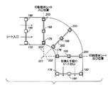
図5A、図5Bを参照すると、本発明の実施例による切換えモジュールのそれぞれ側面図と上断面図が示されている。切換えモジュールは、印刷媒体回転搬送手段と印刷媒体回転搬送バイパスを備える。印刷媒体回転搬送手段は、搬送ニップ172,186,188と、回転ニップ176,198,200を備えるピボットアーム202と、印刷媒体出口ニップ178,180,182を備える。印刷媒体回転バイパスは、ニップアセンブリ162,164,166,168,170を備える。
Referring to FIGS. 5A and 5B, there are shown a side view and a top sectional view, respectively, of a switching module according to an embodiment of the present invention. The switching module includes a printing medium rotation conveyance means and a printing medium rotation conveyance bypass. The print medium rotation conveyance means includes conveyance nips 172, 186, 188, a
図6を参照すると、図5A、図5Bに示される切換えモジュールの動作方法の一例が示されている。まず、印刷媒体シートは、入口ニップ162から切換えモジュールに入る(212)。 Referring to FIG. 6, an example of a method for operating the switching module shown in FIGS. 5A and 5B is shown. First, the print media sheet enters the switching module from the inlet nip 162 (212).
次に、決定ゲート171が上に開き(214)、印刷媒体シートを下側の切換え経路に向けて送り(216)、ここでピンチニップ172,186,188が印刷媒体シートの先端を切換え手段のニップ176,198,200の方向に駆動する。
Next, the
次に、印刷媒体シートの先端は回転/切換えニップ176,198,200に入り(218)、上流の搬送ニップ172,186,188が開き、印刷媒体シートを解放する(220)。 Next, the leading edge of the print media sheet enters the rotation / switching nips 176, 198, 200 (218), and the upstream transport nips 172, 186, 188 open to release the print media sheet (220).
次に、切換えニップ176,198,200は、枢動中心201を中心として枢動するピボットアーム202によって、印刷媒体出口位置まで回転する(222)。
Next, the switching nips 176, 198, 200 are rotated to the print media exit position by the
次に、印刷媒体シートの先端は出口ニップ178,180,182に入り(224)、回転/切換えニップ176,198,200は印刷媒体シートを解放する(226)。 The leading edge of the print media sheet then enters the exit nips 178, 180, 182 (224), and the rotation / switching nips 176, 198, 200 release the print media sheet (226).
最後に、回転/切換えニップ176,198,200は、ピボットアーム202によって、印刷媒体シート入口位置まで戻される(228)。 Finally, the rotation / switching nips 176, 198, 200 are returned to the print media sheet entry position by the pivot arm 202 (228).
図7A、図7Bを参照すると、本発明の別の実施例による切換えモジュールのそれぞれ側面図と上断面図が示されている。この切換えモジュールは、印刷媒体回転搬送手段と印刷媒体回転搬送バイパスを備える。印刷媒体回転搬送手段は、搬送ニップ244,264,262,246,270,268と、回転ニップ256,278,274を備える上段ピボットアームと、回転ニップ248,250,252を備える下段ピボットアームと、第一の決定ゲート242、第二の決定ゲート258、出口ニップ280,282,284を備える。印刷媒体回転搬送手段は、入口ニップ232、搬送ニップ234,236,238,240を備える。
Referring to FIGS. 7A and 7B, there are shown a side view and a top sectional view, respectively, of a switching module according to another embodiment of the present invention. The switching module includes a printing medium rotation conveyance unit and a printing medium rotation conveyance bypass. The print medium rotating and conveying means includes conveying
動作中、第一の決定ゲート242は入ってきた媒体シートを、ゲート本体をそれぞれ下側または上側に回転させることにより、バイパスまたは回転搬送手段のいずれかに送る。回転搬送手段に送られた印刷媒体シートはまず、ニップ244,264,262によって駆動される。その後、印刷媒体シートは、決定ゲート258によって上段ニップ256,278,274か下段ニップ248,250,252に送られる。
In operation, the
図7Aに示されるように、上段ニップ256,278,274は当初、媒体シートを受け取る位置にあり、下段ニップ248,250,252は当初、上段ニップ256,278,274に直交する位置にある。媒体シートを切換える、あるいは回転させるために、上段ニップ256,278,274は上段ニップに関する中心の周囲を約90°回転され、下段ニップは同じ中心の周囲を約90°回転され、この場合、下段ニップは決定ゲート258によって方向付けられた次の印刷媒体シートを受けるように回転され、上段ニップは切換えられた/回転された印刷媒体シートを出口ニップ280,282,284に送るように回転される。
As shown in FIG. 7A, the
特に、次の媒体シートの切換え/回転は、下段回転ニップ248,250,252によって実現され、上段ニップ256,278,274は図7Bに示される印刷媒体シート入口位置まで回転され、このサイクルが繰り返される。
In particular, the next media sheet switching / rotation is accomplished by the lower rotation nips 248, 250, 252 and the
図8を参照すると、図7A、図7Bによる切換えモジュールの動作方法290が示されている。
Referring to FIG. 8, a
まず、切換えゲート1 242が第一の媒体シートをハイウェイから下ろし、回転台へと方向付ける(292)。
First, switching
次に、回転台は、上段ニップが入力された紙の移動方向と同じ方向を向くように位置付けられる(294)。 Next, the turntable is positioned so that the upper nip faces in the same direction as the input paper movement direction (294).
次に、切換えゲート2 258は、第一の媒体シートを回転台の上段ニップの中へと方向付ける(296)。
Next, switching
次に、第一の媒体シートは上段ニップによって制御され、上流ニップが解放される(298)。 The first media sheet is then controlled by the upper nip and the upstream nip is released (298).
次に、回転台は垂直枢軸を中心として90度の方向を指示する(300)。第一の媒体シートは90度回転され、上段が媒体シートの出口方向と一致し、下段が媒体シートの入力方向と一致する。 The turntable then indicates a 90 degree direction about the vertical pivot (300). The first media sheet is rotated 90 degrees, and the upper stage matches the exit direction of the media sheet, and the lower stage matches the input direction of the media sheet.
次に、第一の媒体シートは直交する出口ニップに入り(302)、引き続き印刷モジュールへと移動する。 The first media sheet then enters the orthogonal exit nip (302) and continues to move to the printing module.
次に、切換えゲート1 242は第二の媒体シートをハイウェイから下ろし、回転台へと方向付ける(304)。
Next, switching
次に、切換えゲート2 258は、第二の媒体シートを回転台の下段ニップの中へと方向付ける(306)。
Next, switching
次に、第二の媒体シートは下段ニップによって制御され、上流のニップが解放される(308)。 The second media sheet is then controlled by the lower nip and the upstream nip is released (308).
次に、回転台は垂直枢軸を中心として90度の方向を指示し、第二の媒体シートが90度回転される(310)。この結果、下段は媒体シートの出口方向と一致し、上段は媒体シートの入力方向と一致する。 Next, the turntable indicates a 90 degree direction about the vertical pivot, and the second media sheet is rotated 90 degrees (310). As a result, the lower stage coincides with the outlet direction of the medium sheet, and the upper stage coincides with the input direction of the medium sheet.
次に、後続のシートについて上記のステップが繰り返される(312)。 The above steps are then repeated for subsequent sheets (312).
図9A、図9Bを参照すると、本発明の別の実施例による切換えモジュールのそれぞれ側面図と上断面図が示されている。この切換えモジュールは、印刷媒体回転搬送手段と印刷媒体回転搬送バイパスを備える。印刷媒体回転搬送手段は、入口ニップ332,344,346と、搬送ニップ334,350,352と、回転ニップ336,338と、出口ニップ354,356,358を備える。印刷媒体回転搬送バイパスは搬送ニップ322,324,326,328,330を備える。
Referring to FIGS. 9A and 9B, there are shown a side view and a top sectional view, respectively, of a switching module according to another embodiment of the present invention. The switching module includes a printing medium rotation conveyance unit and a printing medium rotation conveyance bypass. The print medium rotating and conveying means includes inlet nips 332, 344 and 346, conveying
特に、図9A、図9Bの切換えモジュールは、球状の回転ニップ336,338を備える点を除き、図5A、図5Bに示され、説明された切換えモジュールと同様に動作する。球状の回転ニップ336,338は、90度の方向を指示し、媒体シートを回転させる。
In particular, the switching module of FIGS. 9A and 9B operates similarly to the switching module shown and described in FIGS. 5A and 5B, except that it includes spherical
図10A、図10Bを参照すると、本発明のひとつ実施例による回収モジュールのそれぞれ側面図と上断面図が示されている。この回転モジュールは、印刷媒体回転搬送手段と印刷媒体回転搬送バイパスを備える。 Referring to FIGS. 10A and 10B, there are shown a side view and a top sectional view, respectively, of a recovery module according to one embodiment of the present invention. The rotation module includes a printing medium rotation conveyance unit and a printing medium rotation conveyance bypass.
印刷媒体回転搬送手段は、搬送ニップ380,406,404と、回転ニップ376,374,372を備えるピボットアーム371と、印刷媒体出口ニップ392,394,396を備える。印刷媒体回転バイパスは、ニップアセンブリ362,364,366,368,370を備える。
The print medium rotation conveying means includes conveyance nips 380, 406, 404, a
図11を参照すると、図10A、図10Bに示される回収モジュールの動作方法の一例420が示されている。まず、印刷媒体シートは入力ニップ392,394,396で回収モジュールに入る(422)。 Referring to FIG. 11, an example 420 of a method for operating the recovery module shown in FIGS. 10A and 10B is shown. First, the print media sheet enters the collection module at the input nips 392, 394, 396 (422).
次に、印刷媒体シートの先端は、回転/切換えニップ372,374,376に入り(424)、上流搬送ニップ392,394,396が開き、印刷媒体シートを解放する(426)。 Next, the leading edge of the print media sheet enters the rotation / switching nips 372, 374, and 376 (424), and the upstream conveyance nips 392, 394, and 396 are opened to release the print media sheet (426).
次に、切換えニップ372,374,376は、枢動中心369を中心として枢動するピボットアーム371によって、印刷媒体出口位置まで回転する(428)。
The switching nips 372, 374, and 376 are then rotated to the print media exit position by a
次に、印刷媒体シートの先端は、ニップ380,406,404に入り(430)、回転/切換えニップ372,374,376は印刷媒体シートを解放する(432)。
The leading edge of the print media sheet then enters the
最後に、回転/切換えニップ372,374,376は、ピボットアーム371によって印刷媒体シート入口位置まで戻され(434)、切換えられた/回転されたシートは、上側経路出口ニップ370に送られる(436)。 Finally, the rotation / switching nips 372, 374, 376 are returned to the print media sheet entry position by pivot arm 371 (434) and the switched / rotated sheet is fed to upper path exit nip 370 (436). ).
図12A、図12Bを参照すると、本発明の別の実施例による回収モジュールのそれぞれ側面図と上断面図が示されている。この回収モジュールは、印刷媒体回転搬送手段と印刷媒体回転搬送バイパスを備える。印刷媒体回転搬送手段は、搬送ニップ472,474,476と、回転ニップ462,480,478を備える上段ピボットアームと、回転ニップ452,454,456を備える下段ピボットアームと、出口ニップ458,486,484,460,492,490を備える。印刷媒体回転搬送手段は、入口ニップ442と、搬送ニップ444,446,448,450を備える。
Referring to FIGS. 12A and 12B, there are shown a side view and a top sectional view, respectively, of a recovery module according to another embodiment of the present invention. The collection module includes a printing medium rotation conveyance unit and a printing medium rotation conveyance bypass. The print medium rotating and conveying means includes conveying
図13を参照すると、図12A、図12Bによる回収モジュールの操作方法500が示されている。
Referring to FIG. 13, a collection
まず、印刷モジュールは、第一の媒体シートを回収モジュールの入口に方向付ける(502)。 First, the printing module directs the first media sheet to the entrance of the collection module (502).
次に、回転台は、上段ニップが入力された紙の移動方向を向くように位置づけられる(504)。 Next, the turntable is positioned so that the upper nip faces the moving direction of the input paper (504).
次に、切換えゲート(図示せず)は、第一の媒体シートを回転台の上段ニップの方向へと方向付ける(506)。 Next, a switching gate (not shown) directs the first media sheet toward the upper nip of the turntable (506).
次に、第一の媒体シートは回転台の上段ニップによって制御される(508)。 The first media sheet is then controlled by the upper nip of the turntable (508).
次に、回転台は、垂直枢軸を中心として90度を指示する(510)。第一の媒体シートは90度回転され、上段は媒体シートの出口方向と一致し、下段は媒体シートの入力方向と一致する。 The turntable then indicates 90 degrees about the vertical pivot (510). The first media sheet is rotated 90 degrees, the upper row coincides with the exit direction of the media sheet, and the lower row coincides with the input direction of the media sheet.
次に、第一の媒体シートは直交する出口ニップの中に入り、ニップ450を通じて回収ハイウェイと合流する(512)。 The first media sheet then enters the orthogonal exit nip and joins the recovery highway through the nip 450 (512).
次に、印刷モジュールは第二のシートを回収モジュールへと搬送する(514)。 Next, the printing module conveys the second sheet to the collection module (514).
次に、切換えゲート(図示せず)は、第二の媒体シートを回転台の下段ニップのほうに方向付ける(516)。 Next, a switching gate (not shown) directs the second media sheet toward the lower nip of the turntable (516).
次に、第二の媒体シートは下段ニップによって制御され、上流のニップが解放される(518)。 The second media sheet is then controlled by the lower nip and the upstream nip is released (518).
次に、回転台は、垂直枢軸を中心として90度を指示し、第二の媒体シートが90度回転される(520)。これにより、下段は媒体シートの出口方向と一致し、上段は媒体シートの入力方向と一致する。 The turntable then indicates 90 degrees about the vertical pivot and the second media sheet is rotated 90 degrees (520). Accordingly, the lower stage matches the outlet direction of the medium sheet, and the upper stage matches the input direction of the medium sheet.
次に、後続のシートについて上記のステップが繰り返される(522)。 The above steps are then repeated for subsequent sheets (522).
図14A、図14Bを参照すると、本発明の他の実施例による回収モジュールのそれぞれ側面図と上断面図が示されている。この回収モジュールは、印刷媒体回転搬送手段と印刷媒体回転搬送バイパスを備える。印刷媒体回転搬送手段は、搬送ニップ552,554,556と、回転ニップ542,560と、搬送ニップ546,564,562と、出口ニップ548,570,568を備える。印刷媒体回転搬送バイパスは、搬送ニップ532,534,536,538,540を備える。 Referring to FIGS. 14A and 14B, there are shown a side view and a top sectional view, respectively, of a recovery module according to another embodiment of the present invention. The collection module includes a printing medium rotation conveyance unit and a printing medium rotation conveyance bypass. The print medium rotation conveyance unit includes conveyance nips 552, 554, 556, rotation nips 542, 560, conveyance nips 546, 564, 562, and outlet nips 548, 570, 568. The print medium rotation conveyance bypass includes conveyance nips 532, 534, 536, 538, and 540.
特に、図14A、図14Bに示される回収モジュールは、印刷媒体回転輸送手段が球状回転ニップ542,560を有する点を除き、図10A、図10Bに関して示され、説明されたものと同様に動作する。球状回転ニップ542,560は、90度を指示し、媒体シートを回転させる。 In particular, the collection module shown in FIGS. 14A and 14B operates similarly to that shown and described with respect to FIGS. 10A and 10B, except that the print media rotary transport means has spherical rotary nips 542 and 560. . Spherical rotation nips 542 and 560 indicate 90 degrees and rotate the media sheet.
10,12,14,16,50,80,120 印刷システム、18,20,22,56,58,90,92,96,98 切換えモジュール、24,26,28,60,62,100,102,104,106 回収モジュール、30,32,34,36,38,40,64,66,68,70,76,108,110,112,114,116,118,128,130,132 ブリッジ搬送モジュール、42,72,134 印刷媒体シート供給モジュール、44,74 印刷媒体仕上げモジュール、52,54,84,86,88,122,124,126 印刷モジュール、82 回帰輸送モジュール、162,164,166,168,170,362,364,366,368,370 ニップアセンブリ、171,242,258 決定ゲート、172,186,188,234,236,238,240,244,246,262,264,268,270,322,324,326,328,330,334,350,352,380,404,406,444,446,448,450,472,474,476,532,534,536,538,540,546,552,554,556,562,564 搬送ニップ、176,198,200,248,250,252,256,274,278,336,338,372,374,376,452,454,456,462,478,480,542,560 回転/切換えニップ、178,180,182,280,282,284,354,356,358,458,460,484,486,490,492,548,568,570 出口ニップ、201,369 枢動中心、202,371 ピボットアーム、232,332,344,346,392,394,396,442 入口ニップ。 10, 12, 14, 16, 50, 80, 120 printing system, 18, 20, 22, 56, 58, 90, 92, 96, 98 switching module, 24, 26, 28, 60, 62, 100, 102, 104, 106 Recovery module, 30, 32, 34, 36, 38, 40, 64, 66, 68, 70, 76, 108, 110, 112, 114, 116, 118, 128, 130, 132 Bridge transport module, 42 72, 134 Print media sheet supply module, 44, 74 Print media finishing module, 52, 54, 84, 86, 88, 122, 124, 126 Print module, 82 Regression transport module, 162, 164, 166, 168, 170 , 362, 364, 366, 368, 370 Nip assembly, 171, 242, 25 Decision gates 172, 186, 188, 234, 236, 238, 240, 244, 246, 262, 264, 268, 270, 322, 324, 326, 328, 330, 334, 350, 352, 380, 404, 406 , 444, 446, 448, 450, 472, 474, 476, 532, 534, 536, 538, 540, 546, 552, 554, 556, 562, 564 Conveying nip, 176, 198, 200, 248, 250, 252 256, 274, 278, 336, 338, 372, 374, 376, 452, 454, 456, 462, 478, 480, 542, 560 Rotation / switching nip, 178, 180, 182, 280, 282, 284, 354 , 356, 358, 458, 460, 484, 486, 49 , 492,548,568,570 exit nip, 201,369 pivotal center, 202,371 pivot arm, 232,332,344,346,392,394,396,442 inlet nip.
Claims (4)
印刷媒体入力と、
前記印刷媒体入力に作動的に接続された印刷媒体回転バイパスと、
前記印刷媒体入力に作動的に接続された印刷媒体回転搬送手段と、
前記印刷媒体回転バイパスに作動的に接続された第一の印刷媒体出力と、
前記印刷媒体回転搬送手段に作動的に接続された第二の印刷媒体出力と、
を備え、
前記印刷媒体回転バイパスは、印刷媒体シートを選択的に受け取り、前記印刷媒体シートを前記第一の印刷媒体出力に搬送するように構成され、前記印刷媒体回転搬送手段は、印刷媒体シートを選択的に受け取り、前記印刷媒体シートを前記印刷媒体シートの平面と直交する軸を中心に回転させ、前記回転された印刷媒体シートを前記第二の印刷媒体出力に搬送するように構成されていることを特徴とする印刷媒体回転搬送装置。 A printing medium rotating and conveying device,
Print media input,
A print media rotation bypass operatively connected to the print media input;
Printing medium rotating and conveying means operatively connected to the printing medium input;
A first print media output operatively connected to the print media rotation bypass;
A second print medium output operatively connected to the print medium rotation transport means;
With
The print media rotation bypass is configured to selectively receive a print media sheet and transport the print media sheet to the first print media output, and the print media rotation transport means selectively selects the print media sheet. The print medium sheet is rotated about an axis orthogonal to the plane of the print medium sheet, and the rotated print medium sheet is conveyed to the second print medium output. A printing medium rotating and conveying apparatus.
前記印刷媒体回転搬送手段はさらに、
ピボットアームと、
前記ピボットアームに作動的に接続され、共通平面に沿って印刷媒体シートを搬送するよう整列されたひとつまたは複数のピボットアームピンチニップと、
を備え、
前記印刷媒体回転搬送手段は、前記ピボットアームを所定の角度だけ回転させて、印刷媒体シートを搬送するように構成されていることを特徴とする印刷媒体回転搬送装置。 The print medium rotating and conveying apparatus according to claim 1,
The printing medium rotating and conveying means further includes
A pivot arm,
One or more pivot arm pinch nips operatively connected to the pivot arm and aligned to convey the print media sheet along a common plane;
With
The printing medium rotating / conveying device is configured to convey the printing medium sheet by rotating the pivot arm by a predetermined angle.
前記印刷媒体回転バイパスは、
印刷媒体シートを前記印刷媒体入力から前記第一の印刷媒体出力へと搬送するように整列されたひとつまたは複数のニップを備え、
前記印刷媒体回転搬送手段は、
印刷媒体シートを前記ピボットアームピンチニップへと搬送するように整列されたひとつまたは複数のピンチニップを備えることを特徴とする印刷媒体回転搬送装置。 The print medium rotating and conveying apparatus according to claim 2,
The print medium rotation bypass is
Comprising one or more nips arranged to convey a print media sheet from the print media input to the first print media output;
The printing medium rotating and conveying means is
A print medium rotating and conveying apparatus comprising one or more pinch nips arranged to convey a print medium sheet to the pivot arm pinch nip.
印刷媒体入力と、
印刷媒体出力と、
を含む第一の印刷モジュールと、
印刷媒体入力と、
第一の印刷媒体出力と、
前記第一の印刷モジュールの印刷媒体入力に作動的に接続された第二の印刷媒体出力と、
を含む印刷媒体切換えモジュールと、
を備え、
前記切換えモジュールは、印刷媒体シートを、前記印刷媒体シートの平面に直交する軸を中心として選択的に回転させ、前記印刷媒体シートを所定の角度だけ回転させ、前記印刷媒体シートをその後の画像マーキングのために前記第一の印刷モジュール印刷媒体入力に送るように構成され、前記切換えモジュールは、印刷媒体シートを前記印刷媒体入力から前記第一の印刷媒体出力に選択的に送るように構成されていることを特徴とする印刷システム。 A printing system,
Print media input,
Print media output;
A first printing module including:
Print media input,
A first print media output;
A second print media output operatively connected to the print media input of the first print module;
A print medium switching module including:
With
The switching module selectively rotates the print media sheet about an axis orthogonal to the plane of the print media sheet, rotates the print media sheet by a predetermined angle, and causes the print media sheet to be subjected to subsequent image marking. The switching module is configured to selectively send a print media sheet from the print media input to the first print media output. A printing system characterized by
Applications Claiming Priority (2)
| Application Number | Priority Date | Filing Date | Title |
|---|---|---|---|
| US11/595,630 US7819401B2 (en) | 2006-11-09 | 2006-11-09 | Print media rotary transport apparatus and method |
| US11/595,630 | 2006-11-09 |
Publications (3)
| Publication Number | Publication Date |
|---|---|
| JP2008120598A true JP2008120598A (en) | 2008-05-29 |
| JP2008120598A5 JP2008120598A5 (en) | 2010-12-16 |
| JP4906681B2 JP4906681B2 (en) | 2012-03-28 |
Family
ID=39050718
Family Applications (1)
| Application Number | Title | Priority Date | Filing Date |
|---|---|---|---|
| JP2007290591A Expired - Fee Related JP4906681B2 (en) | 2006-11-09 | 2007-11-08 | Rotating and conveying apparatus for printing media and printing system |
Country Status (5)
| Country | Link |
|---|---|
| US (1) | US7819401B2 (en) |
| EP (1) | EP1921036B1 (en) |
| JP (1) | JP4906681B2 (en) |
| KR (1) | KR101298051B1 (en) |
| CN (1) | CN101181847B (en) |
Cited By (4)
| Publication number | Priority date | Publication date | Assignee | Title |
|---|---|---|---|---|
| JP2009298574A (en) * | 2008-06-17 | 2009-12-24 | Konica Minolta Business Technologies Inc | Paper conveyance relay unit and image forming system |
| JP2010001088A (en) * | 2008-06-18 | 2010-01-07 | Konica Minolta Business Technologies Inc | Paper conveying relay unit and image forming system |
| CN105581315A (en) * | 2015-11-03 | 2016-05-18 | 葛晓军 | Method for fermenting fish sauce from acaudina molpadioides semper |
| JP2020070167A (en) * | 2018-11-01 | 2020-05-07 | 日立オムロンターミナルソリューションズ株式会社 | Sheet turning and conveying mechanism, front-back reversing mechanism, sheet processing device, and cash handling device |
Families Citing this family (11)
| Publication number | Priority date | Publication date | Assignee | Title |
|---|---|---|---|---|
| US8169626B2 (en) | 2008-08-29 | 2012-05-01 | Xerox Corporation | Using buffers to support uncertainties in marking engine execution |
| US8020847B2 (en) * | 2009-02-06 | 2011-09-20 | Goss International Americas, Inc. | Multiple delivery web conversion apparatus and method of producing and delivering variable printed products |
| US8002257B2 (en) * | 2009-02-06 | 2011-08-23 | Goss International Americas, Inc. | Web conversion and collating apparatus and method |
| US8020845B2 (en) * | 2009-02-06 | 2011-09-20 | Goss International Americas, Inc. | Single level web conversion apparatus and method |
| US7963515B2 (en) | 2009-02-06 | 2011-06-21 | Goss International Americas, Inc. | Adjustable delivery web conversion apparatus and method |
| JP2010208834A (en) * | 2009-03-12 | 2010-09-24 | Konica Minolta Business Technologies Inc | Double-sided image forming device |
| US8200140B2 (en) * | 2009-04-16 | 2012-06-12 | Xerox Corporation | Modular printing system having a module with a bypass path |
| DE102012021383B4 (en) * | 2012-10-31 | 2015-10-15 | Eastman Kodak Company | Turning unit and method for turning a sheet |
| WO2019106510A1 (en) | 2017-11-29 | 2019-06-06 | Landa Corporation Ltd. | Protection of components of digital printing systems |
| US11820130B2 (en) | 2019-04-03 | 2023-11-21 | Landa Corporation Ltd. | Preventing damage to printed substrates conveyed in a printing system |
| CN112777384B (en) * | 2020-12-30 | 2023-01-13 | 保定市跃进纸箱有限公司 | A environment-friendly printing machine for carton production |
Citations (13)
| Publication number | Priority date | Publication date | Assignee | Title |
|---|---|---|---|---|
| US2729324A (en) * | 1952-10-30 | 1956-01-03 | Cutler Hammer Inc | Horizontal turns for conveyers |
| US4160500A (en) * | 1977-09-12 | 1979-07-10 | Ga-Vehren Engineering Company | Turn conveyor |
| JPS57170318A (en) * | 1981-03-24 | 1982-10-20 | Ee Tsuee Haauiru Gmbh Unto Co | Device for changing feeding direction of separate article |
| US4591046A (en) * | 1983-04-04 | 1986-05-27 | R. R. Donnelley & Sons Company | Turntable transfer mechanism for conveyors |
| JPS6439342A (en) * | 1987-08-04 | 1989-02-09 | Mitsubishi Metal Corp | Cutting tip made of cermet |
| JPH01313252A (en) * | 1988-06-08 | 1989-12-18 | Hitachi Ltd | Paper sheet direction changing device |
| JPH04133955A (en) * | 1990-09-25 | 1992-05-07 | Minolta Camera Co Ltd | Image forming device |
| JP2003160259A (en) * | 2001-11-21 | 2003-06-03 | Fuji Xerox Co Ltd | Sheet conveying device and image forming device using the same |
| JP2003207954A (en) * | 2001-10-18 | 2003-07-25 | Xerox Corp | Constant inverter speed timing strategy for duplex sheets in tandem printer |
| JP2004359468A (en) * | 2003-06-06 | 2004-12-24 | Xerox Corp | A plurality of printers having general-purpose property and flexibility and a plurality of sheet finish machine sheet integration system |
| JP2006016210A (en) * | 2004-06-30 | 2006-01-19 | Xerox Corp | Passage for flexible paper using multiple direction passage module |
| JP2006056256A (en) * | 2004-08-23 | 2006-03-02 | Xerox Corp | Parallel printing architecture using image marking engine modules |
| JP2006285256A (en) * | 2005-03-31 | 2006-10-19 | Xerox Corp | Parallel printing architecture with parallel horizontal printing modules |
Family Cites Families (74)
| Publication number | Priority date | Publication date | Assignee | Title |
|---|---|---|---|---|
| CH570325A5 (en) * | 1974-08-27 | 1975-12-15 | Grapha Holding Ag | |
| US4579446A (en) * | 1982-07-12 | 1986-04-01 | Canon Kabushiki Kaisha | Both-side recording system |
| US4587532A (en) * | 1983-05-02 | 1986-05-06 | Canon Kabushiki Kaisha | Recording apparatus producing multiple copies simultaneously |
| US4756521A (en) * | 1987-03-12 | 1988-07-12 | Pitney Bowes Inc. | Methods and apparatus for turning flat articles |
| JP2590477B2 (en) * | 1987-05-13 | 1997-03-12 | 富士ゼロックス株式会社 | Paper transport direction change device |
| DE3852234T2 (en) * | 1987-08-12 | 1995-05-04 | Canon Kk | Sheet conveying apparatus and sheet conveying method. |
| US4836119A (en) * | 1988-03-21 | 1989-06-06 | The Charles Stark Draper Laboratory, Inc. | Sperical ball positioning apparatus for seamed limp material article assembly system |
| JP2636441B2 (en) * | 1989-11-09 | 1997-07-30 | 富士ゼロックス株式会社 | Image recording device |
| US5095342A (en) * | 1990-09-28 | 1992-03-10 | Xerox Corporation | Methods for sheet scheduling in an imaging system having an endless duplex paper path loop |
| US5080340A (en) * | 1991-01-02 | 1992-01-14 | Eastman Kodak Company | Modular finisher for a reproduction apparatus |
| US5159395A (en) * | 1991-08-29 | 1992-10-27 | Xerox Corporation | Method of scheduling copy sheets in a dual mode duplex printing system |
| US5272511A (en) * | 1992-04-30 | 1993-12-21 | Xerox Corporation | Sheet inserter and methods of inserting sheets into a continuous stream of sheets |
| US5358238A (en) * | 1993-04-27 | 1994-10-25 | Xerox Corporation | Shared user printer output dynamic "mailbox" system |
| US5326093A (en) * | 1993-05-24 | 1994-07-05 | Xerox Corporation | Universal interface module interconnecting various copiers and printers with various sheet output processors |
| US5473419A (en) * | 1993-11-08 | 1995-12-05 | Eastman Kodak Company | Image forming apparatus having a duplex path with an inverter |
| US5596416A (en) * | 1994-01-13 | 1997-01-21 | T/R Systems | Multiple printer module electrophotographic printing device |
| US5525031A (en) * | 1994-02-18 | 1996-06-11 | Xerox Corporation | Automated print jobs distribution system for shared user centralized printer |
| US5778377A (en) * | 1994-11-04 | 1998-07-07 | International Business Machines Corporation | Table driven graphical user interface |
| US5570172A (en) * | 1995-01-18 | 1996-10-29 | Xerox Corporation | Two up high speed printing system |
| US5557367A (en) * | 1995-03-27 | 1996-09-17 | Xerox Corporation | Method and apparatus for optimizing scheduling in imaging devices |
| US5489969A (en) * | 1995-03-27 | 1996-02-06 | Xerox Corporation | Apparatus and method of controlling interposition of sheet in a stream of imaged substrates |
| US5504568A (en) * | 1995-04-21 | 1996-04-02 | Xerox Corporation | Print sequence scheduling system for duplex printing apparatus |
| US5629762A (en) * | 1995-06-07 | 1997-05-13 | Eastman Kodak Company | Image forming apparatus having a duplex path and/or an inverter |
| US5710968A (en) * | 1995-08-28 | 1998-01-20 | Xerox Corporation | Bypass transport loop sheet insertion system |
| US5568246A (en) * | 1995-09-29 | 1996-10-22 | Xerox Corporation | High productivity dual engine simplex and duplex printing system using a reversible duplex path |
| US6297886B1 (en) * | 1996-06-05 | 2001-10-02 | John S. Cornell | Tandem printer printing apparatus |
| US6476923B1 (en) * | 1996-06-05 | 2002-11-05 | John S. Cornell | Tandem printer printing apparatus |
| US6493098B1 (en) * | 1996-06-05 | 2002-12-10 | John S. Cornell | Desk-top printer and related method for two-sided printing |
| US5995721A (en) * | 1996-10-18 | 1999-11-30 | Xerox Corporation | Distributed printing system |
| US6059284A (en) * | 1997-01-21 | 2000-05-09 | Xerox Corporation | Process, lateral and skew sheet positioning apparatus and method |
| US5884910A (en) * | 1997-08-18 | 1999-03-23 | Xerox Corporation | Evenly retractable and self-leveling nips sheets ejection system |
| US6210813B1 (en) * | 1998-09-02 | 2001-04-03 | Micron Technology, Inc. | Forming metal silicide resistant to subsequent thermal processing |
| US6125248A (en) * | 1998-11-30 | 2000-09-26 | Xerox Corporation | Electrostatographic reproduction machine including a plurality of selectable fusing assemblies |
| IT1308720B1 (en) * | 1999-06-08 | 2002-01-10 | Tecnau Srl | DYNAMIC SEQUENCER FOR PRINTED SHEETS OF PAPER |
| US6241242B1 (en) * | 1999-10-12 | 2001-06-05 | Hewlett-Packard Company | Deskew of print media |
| US6384918B1 (en) * | 1999-11-24 | 2002-05-07 | Xerox Corporation | Spectrophotometer for color printer color control with displacement insensitive optics |
| US6577925B1 (en) * | 1999-11-24 | 2003-06-10 | Xerox Corporation | Apparatus and method of distributed object handling |
| US7864346B2 (en) * | 2000-05-16 | 2011-01-04 | Xerox Corporation | Apparatus and method for describing, planning and automatically programming complex finishing tasks |
| US6450711B1 (en) * | 2000-12-05 | 2002-09-17 | Xerox Corporation | High speed printer with dual alternate sheet inverters |
| US6550762B2 (en) * | 2000-12-05 | 2003-04-22 | Xerox Corporation | High speed printer with dual alternate sheet inverters |
| US6633790B2 (en) * | 2001-01-29 | 2003-10-14 | Xerox Corporation | Systems and methods for optimizing a production facility |
| US6607320B2 (en) * | 2001-03-30 | 2003-08-19 | Xerox Corporation | Mobius combination of reversion and return path in a paper transport system |
| US6554276B2 (en) * | 2001-03-30 | 2003-04-29 | Xerox Corporation | Flexible sheet reversion using an omni-directional transport system |
| US6621576B2 (en) * | 2001-05-22 | 2003-09-16 | Xerox Corporation | Color imager bar based spectrophotometer for color printer color control system |
| US6633382B2 (en) * | 2001-05-22 | 2003-10-14 | Xerox Corporation | Angular, azimuthal and displacement insensitive spectrophotometer for color printer color control systems |
| US6639669B2 (en) * | 2001-09-10 | 2003-10-28 | Xerox Corporation | Diagnostics for color printer on-line spectrophotometer control system |
| US6612571B2 (en) * | 2001-12-06 | 2003-09-02 | Xerox Corporation | Sheet conveying device having multiple outputs |
| US6476376B1 (en) * | 2002-01-16 | 2002-11-05 | Xerox Corporation | Two dimensional object position sensor |
| DE10220908C1 (en) * | 2002-05-10 | 2003-06-18 | Pitney Bowes Technologies Gmbh | Mail insertion station for a post processing system includes intermediate transfer belt system set at angle between envelope supply belt and insertion station |
| US7233405B2 (en) * | 2002-10-30 | 2007-06-19 | Palo Alto Research Center, Incorporated | Planning and scheduling reconfigurable systems with regular and diagnostic jobs |
| US8315898B2 (en) * | 2002-10-30 | 2012-11-20 | Palo Alto Research Center, Incorporated | Planning and scheduling reconfigurable systems around off-line resources |
| US7230736B2 (en) | 2002-10-30 | 2007-06-12 | Palo Alto Research Center, Incorporated | Planning and scheduling reconfigurable systems with alternative capabilities |
| US6944838B2 (en) * | 2003-02-03 | 2005-09-13 | Cadence Design Systems, Inc. | Method and system for design verification using proof-partitioning |
| US7093831B2 (en) * | 2003-02-04 | 2006-08-22 | Palo Alto Research Center Inc. | Media path modules |
| US20040150156A1 (en) * | 2003-02-04 | 2004-08-05 | Palo Alto Research Center, Incorporated. | Frameless media path modules |
| US6895292B2 (en) * | 2003-04-28 | 2005-05-17 | Palo Alto Research Center Inc. | Predictive and preemptive planning and scheduling for different job priorities system and method |
| US7139629B2 (en) * | 2003-04-28 | 2006-11-21 | Palo Alto Research Center Incorporated | Planning and scheduling for failure recovery system and method |
| US6856845B2 (en) * | 2003-04-28 | 2005-02-15 | Palo Alto Research Center Inc. | Monitoring and reporting incremental job status system and method |
| JP4350450B2 (en) | 2003-08-04 | 2009-10-21 | キヤノン株式会社 | Sheet conveying apparatus, image forming apparatus, and image reading apparatus |
| US6819906B1 (en) * | 2003-08-29 | 2004-11-16 | Xerox Corporation | Printer output sets compiler to stacker system |
| US6973286B2 (en) * | 2004-01-21 | 2005-12-06 | Xerox Corporation | High print rate merging and finishing system for parallel printing |
| US7188929B2 (en) * | 2004-08-13 | 2007-03-13 | Xerox Corporation | Parallel printing architecture with containerized image marking engines |
| US7123873B2 (en) * | 2004-08-23 | 2006-10-17 | Xerox Corporation | Printing system with inverter disposed for media velocity buffering and registration |
| US7024152B2 (en) * | 2004-08-23 | 2006-04-04 | Xerox Corporation | Printing system with horizontal highway and single pass duplex |
| US7336920B2 (en) * | 2004-09-28 | 2008-02-26 | Xerox Corporation | Printing system |
| US7324779B2 (en) * | 2004-09-28 | 2008-01-29 | Xerox Corporation | Printing system with primary and secondary fusing devices |
| US7751072B2 (en) * | 2004-09-29 | 2010-07-06 | Xerox Corporation | Automated modification of a marking engine in a printing system |
| US7310108B2 (en) * | 2004-11-30 | 2007-12-18 | Xerox Corporation | Printing system |
| US7162172B2 (en) * | 2004-11-30 | 2007-01-09 | Xerox Corporation | Semi-automatic image quality adjustment for multiple marking engine systems |
| US7412180B2 (en) * | 2004-11-30 | 2008-08-12 | Xerox Corporation | Glossing system for use in a printing system |
| US20060114497A1 (en) * | 2004-11-30 | 2006-06-01 | Xerox Corporation | Printing system |
| US7283762B2 (en) * | 2004-11-30 | 2007-10-16 | Xerox Corporation | Glossing system for use in a printing architecture |
| US7791751B2 (en) * | 2004-11-30 | 2010-09-07 | Palo Alto Research Corporation | Printing systems |
| US7416185B2 (en) | 2005-03-25 | 2008-08-26 | Xerox Corporation | Inverter with return/bypass paper path |
-
2006
- 2006-11-09 US US11/595,630 patent/US7819401B2/en not_active Expired - Fee Related
-
2007
- 2007-11-05 EP EP07119998.8A patent/EP1921036B1/en not_active Ceased
- 2007-11-05 KR KR1020070111943A patent/KR101298051B1/en not_active Expired - Fee Related
- 2007-11-08 CN CN2007101596765A patent/CN101181847B/en not_active Expired - Fee Related
- 2007-11-08 JP JP2007290591A patent/JP4906681B2/en not_active Expired - Fee Related
Patent Citations (13)
| Publication number | Priority date | Publication date | Assignee | Title |
|---|---|---|---|---|
| US2729324A (en) * | 1952-10-30 | 1956-01-03 | Cutler Hammer Inc | Horizontal turns for conveyers |
| US4160500A (en) * | 1977-09-12 | 1979-07-10 | Ga-Vehren Engineering Company | Turn conveyor |
| JPS57170318A (en) * | 1981-03-24 | 1982-10-20 | Ee Tsuee Haauiru Gmbh Unto Co | Device for changing feeding direction of separate article |
| US4591046A (en) * | 1983-04-04 | 1986-05-27 | R. R. Donnelley & Sons Company | Turntable transfer mechanism for conveyors |
| JPS6439342A (en) * | 1987-08-04 | 1989-02-09 | Mitsubishi Metal Corp | Cutting tip made of cermet |
| JPH01313252A (en) * | 1988-06-08 | 1989-12-18 | Hitachi Ltd | Paper sheet direction changing device |
| JPH04133955A (en) * | 1990-09-25 | 1992-05-07 | Minolta Camera Co Ltd | Image forming device |
| JP2003207954A (en) * | 2001-10-18 | 2003-07-25 | Xerox Corp | Constant inverter speed timing strategy for duplex sheets in tandem printer |
| JP2003160259A (en) * | 2001-11-21 | 2003-06-03 | Fuji Xerox Co Ltd | Sheet conveying device and image forming device using the same |
| JP2004359468A (en) * | 2003-06-06 | 2004-12-24 | Xerox Corp | A plurality of printers having general-purpose property and flexibility and a plurality of sheet finish machine sheet integration system |
| JP2006016210A (en) * | 2004-06-30 | 2006-01-19 | Xerox Corp | Passage for flexible paper using multiple direction passage module |
| JP2006056256A (en) * | 2004-08-23 | 2006-03-02 | Xerox Corp | Parallel printing architecture using image marking engine modules |
| JP2006285256A (en) * | 2005-03-31 | 2006-10-19 | Xerox Corp | Parallel printing architecture with parallel horizontal printing modules |
Cited By (8)
| Publication number | Priority date | Publication date | Assignee | Title |
|---|---|---|---|---|
| JP2009298574A (en) * | 2008-06-17 | 2009-12-24 | Konica Minolta Business Technologies Inc | Paper conveyance relay unit and image forming system |
| US8052136B2 (en) | 2008-06-17 | 2011-11-08 | Konica Minolta Business Technologies, Inc. | Sheet conveyance relay unit and image forming system using the same unit |
| JP2010001088A (en) * | 2008-06-18 | 2010-01-07 | Konica Minolta Business Technologies Inc | Paper conveying relay unit and image forming system |
| US8038152B2 (en) | 2008-06-18 | 2011-10-18 | Konica Minolta Business Technologies, Inc. | Sheet conveyance relay unit and image forming system using the same unit |
| CN105581315A (en) * | 2015-11-03 | 2016-05-18 | 葛晓军 | Method for fermenting fish sauce from acaudina molpadioides semper |
| JP2020070167A (en) * | 2018-11-01 | 2020-05-07 | 日立オムロンターミナルソリューションズ株式会社 | Sheet turning and conveying mechanism, front-back reversing mechanism, sheet processing device, and cash handling device |
| WO2020090139A1 (en) * | 2018-11-01 | 2020-05-07 | 日立オムロンターミナルソリューションズ株式会社 | Paper sheet turning and transporting mechanism, front-rear inverting mechanism, paper sheet treatment device, and cash handling device |
| JP7198634B2 (en) | 2018-11-01 | 2023-01-04 | 日立チャネルソリューションズ株式会社 | Sheet material turnover mechanism, sheet material processing device, and cash handling device |
Also Published As
| Publication number | Publication date |
|---|---|
| KR20080042694A (en) | 2008-05-15 |
| EP1921036A2 (en) | 2008-05-14 |
| JP4906681B2 (en) | 2012-03-28 |
| US20080112743A1 (en) | 2008-05-15 |
| EP1921036B1 (en) | 2017-06-07 |
| EP1921036A3 (en) | 2010-09-22 |
| KR101298051B1 (en) | 2013-08-20 |
| CN101181847B (en) | 2012-02-22 |
| US7819401B2 (en) | 2010-10-26 |
| CN101181847A (en) | 2008-05-21 |
Similar Documents
| Publication | Publication Date | Title |
|---|---|---|
| JP4906681B2 (en) | Rotating and conveying apparatus for printing media and printing system | |
| EP1630624B1 (en) | Printing system with horizontal bypass and single pass duplex | |
| US20060039728A1 (en) | Printing system with inverter disposed for media velocity buffering and registration | |
| US8200140B2 (en) | Modular printing system having a module with a bypass path | |
| JP2004359468A (en) | A plurality of printers having general-purpose property and flexibility and a plurality of sheet finish machine sheet integration system | |
| CN103848258A (en) | Sheet stacking apparatus, image forming system and sheet stacking method | |
| US8366104B2 (en) | Sheet conveying device and recording apparatus | |
| JP4776991B2 (en) | Flexible paper path using a multi-directional path module | |
| JP5274538B2 (en) | Paper transport device and image forming apparatus | |
| JP4193925B2 (en) | Image forming system | |
| JP2008044785A (en) | Automatic feeder apparatus | |
| CN100524061C (en) | Image forming apparatus and paper processing method | |
| JPH05193212A (en) | Apparatus for forming image on word printing medium | |
| JP5760725B2 (en) | Paper processing apparatus and image forming system | |
| KR101578942B1 (en) | Multi-sheet buffer module and printing system comprising multi-sheet buffer module | |
| CN101400594A (en) | Flaky material steering equipment | |
| CN103420205A (en) | Sheet processing apparatus and image forming system | |
| JP7159706B2 (en) | Relay conveying device and image forming system | |
| JP4325341B2 (en) | Paper orientation conversion device, post-processing device, and image forming device | |
| JPH10148983A (en) | Paper processor | |
| US7566053B2 (en) | Media transport system | |
| JP2020007161A (en) | Post-processing device and image formation system equipped therewith | |
| JP2011173716A (en) | Document carrying device | |
| JP2009018886A (en) | Image reading device | |
| US9250594B2 (en) | Systems and methods for implementing an asynchronous buffering module with an integrated registration function for inline printing an image forming system |
Legal Events
| Date | Code | Title | Description |
|---|---|---|---|
| A521 | Request for written amendment filed |
Free format text: JAPANESE INTERMEDIATE CODE: A523 Effective date: 20101102 |
|
| A621 | Written request for application examination |
Free format text: JAPANESE INTERMEDIATE CODE: A621 Effective date: 20101102 |
|
| A871 | Explanation of circumstances concerning accelerated examination |
Free format text: JAPANESE INTERMEDIATE CODE: A871 Effective date: 20101102 |
|
| A975 | Report on accelerated examination |
Free format text: JAPANESE INTERMEDIATE CODE: A971005 Effective date: 20101215 |
|
| A131 | Notification of reasons for refusal |
Free format text: JAPANESE INTERMEDIATE CODE: A131 Effective date: 20110104 |
|
| A521 | Request for written amendment filed |
Free format text: JAPANESE INTERMEDIATE CODE: A523 Effective date: 20110401 |
|
| A131 | Notification of reasons for refusal |
Free format text: JAPANESE INTERMEDIATE CODE: A131 Effective date: 20110628 |
|
| A521 | Request for written amendment filed |
Free format text: JAPANESE INTERMEDIATE CODE: A523 Effective date: 20110927 |
|
| TRDD | Decision of grant or rejection written | ||
| A01 | Written decision to grant a patent or to grant a registration (utility model) |
Free format text: JAPANESE INTERMEDIATE CODE: A01 Effective date: 20111213 |
|
| A01 | Written decision to grant a patent or to grant a registration (utility model) |
Free format text: JAPANESE INTERMEDIATE CODE: A01 |
|
| A61 | First payment of annual fees (during grant procedure) |
Free format text: JAPANESE INTERMEDIATE CODE: A61 Effective date: 20120110 |
|
| FPAY | Renewal fee payment (event date is renewal date of database) |
Free format text: PAYMENT UNTIL: 20150120 Year of fee payment: 3 |
|
| R150 | Certificate of patent or registration of utility model |
Ref document number: 4906681 Country of ref document: JP Free format text: JAPANESE INTERMEDIATE CODE: R150 Free format text: JAPANESE INTERMEDIATE CODE: R150 |
|
| R250 | Receipt of annual fees |
Free format text: JAPANESE INTERMEDIATE CODE: R250 |
|
| R250 | Receipt of annual fees |
Free format text: JAPANESE INTERMEDIATE CODE: R250 |
|
| R250 | Receipt of annual fees |
Free format text: JAPANESE INTERMEDIATE CODE: R250 |
|
| R250 | Receipt of annual fees |
Free format text: JAPANESE INTERMEDIATE CODE: R250 |
|
| LAPS | Cancellation because of no payment of annual fees |