JP2008100059A - Vertebral connecting member - Google Patents
Vertebral connecting member Download PDFInfo
- Publication number
- JP2008100059A JP2008100059A JP2007257987A JP2007257987A JP2008100059A JP 2008100059 A JP2008100059 A JP 2008100059A JP 2007257987 A JP2007257987 A JP 2007257987A JP 2007257987 A JP2007257987 A JP 2007257987A JP 2008100059 A JP2008100059 A JP 2008100059A
- Authority
- JP
- Japan
- Prior art keywords
- head
- rod
- vertebra
- screw
- holding
- Prior art date
- Legal status (The legal status is an assumption and is not a legal conclusion. Google has not performed a legal analysis and makes no representation as to the accuracy of the status listed.)
- Granted
Links
Images


Classifications
-
- A—HUMAN NECESSITIES
- A61—MEDICAL OR VETERINARY SCIENCE; HYGIENE
- A61B—DIAGNOSIS; SURGERY; IDENTIFICATION
- A61B17/00—Surgical instruments, devices or methods
- A61B17/56—Surgical instruments or methods for treatment of bones or joints; Devices specially adapted therefor
- A61B17/58—Surgical instruments or methods for treatment of bones or joints; Devices specially adapted therefor for osteosynthesis, e.g. bone plates, screws or setting implements
- A61B17/68—Internal fixation devices, including fasteners and spinal fixators, even if a part thereof projects from the skin
- A61B17/80—Cortical plates, i.e. bone plates; Instruments for holding or positioning cortical plates, or for compressing bones attached to cortical plates
-
- A—HUMAN NECESSITIES
- A61—MEDICAL OR VETERINARY SCIENCE; HYGIENE
- A61B—DIAGNOSIS; SURGERY; IDENTIFICATION
- A61B17/00—Surgical instruments, devices or methods
- A61B17/56—Surgical instruments or methods for treatment of bones or joints; Devices specially adapted therefor
- A61B17/58—Surgical instruments or methods for treatment of bones or joints; Devices specially adapted therefor for osteosynthesis, e.g. bone plates, screws or setting implements
- A61B17/68—Internal fixation devices, including fasteners and spinal fixators, even if a part thereof projects from the skin
- A61B17/70—Spinal positioners or stabilisers, e.g. stabilisers comprising fluid filler in an implant
- A61B17/7001—Screws or hooks combined with longitudinal elements which do not contact vertebrae
- A61B17/7035—Screws or hooks, wherein a rod-clamping part and a bone-anchoring part can pivot relative to each other
- A61B17/7037—Screws or hooks, wherein a rod-clamping part and a bone-anchoring part can pivot relative to each other wherein pivoting is blocked when the rod is clamped
-
- A—HUMAN NECESSITIES
- A61—MEDICAL OR VETERINARY SCIENCE; HYGIENE
- A61B—DIAGNOSIS; SURGERY; IDENTIFICATION
- A61B17/00—Surgical instruments, devices or methods
- A61B17/56—Surgical instruments or methods for treatment of bones or joints; Devices specially adapted therefor
- A61B17/58—Surgical instruments or methods for treatment of bones or joints; Devices specially adapted therefor for osteosynthesis, e.g. bone plates, screws or setting implements
- A61B17/68—Internal fixation devices, including fasteners and spinal fixators, even if a part thereof projects from the skin
- A61B17/72—Intramedullary devices, e.g. pins or nails
-
- A—HUMAN NECESSITIES
- A61—MEDICAL OR VETERINARY SCIENCE; HYGIENE
- A61B—DIAGNOSIS; SURGERY; IDENTIFICATION
- A61B17/00—Surgical instruments, devices or methods
- A61B17/56—Surgical instruments or methods for treatment of bones or joints; Devices specially adapted therefor
- A61B17/58—Surgical instruments or methods for treatment of bones or joints; Devices specially adapted therefor for osteosynthesis, e.g. bone plates, screws or setting implements
- A61B17/68—Internal fixation devices, including fasteners and spinal fixators, even if a part thereof projects from the skin
- A61B17/82—Internal fixation devices, including fasteners and spinal fixators, even if a part thereof projects from the skin for bone cerclage
-
- A—HUMAN NECESSITIES
- A61—MEDICAL OR VETERINARY SCIENCE; HYGIENE
- A61B—DIAGNOSIS; SURGERY; IDENTIFICATION
- A61B17/00—Surgical instruments, devices or methods
- A61B17/56—Surgical instruments or methods for treatment of bones or joints; Devices specially adapted therefor
- A61B17/58—Surgical instruments or methods for treatment of bones or joints; Devices specially adapted therefor for osteosynthesis, e.g. bone plates, screws or setting implements
- A61B17/68—Internal fixation devices, including fasteners and spinal fixators, even if a part thereof projects from the skin
- A61B17/84—Fasteners therefor or fasteners being internal fixation devices
- A61B17/86—Pins or screws or threaded wires; nuts therefor
-
- A—HUMAN NECESSITIES
- A61—MEDICAL OR VETERINARY SCIENCE; HYGIENE
- A61B—DIAGNOSIS; SURGERY; IDENTIFICATION
- A61B17/00—Surgical instruments, devices or methods
- A61B17/56—Surgical instruments or methods for treatment of bones or joints; Devices specially adapted therefor
- A61B17/58—Surgical instruments or methods for treatment of bones or joints; Devices specially adapted therefor for osteosynthesis, e.g. bone plates, screws or setting implements
- A61B17/68—Internal fixation devices, including fasteners and spinal fixators, even if a part thereof projects from the skin
- A61B17/70—Spinal positioners or stabilisers, e.g. stabilisers comprising fluid filler in an implant
- A61B17/7001—Screws or hooks combined with longitudinal elements which do not contact vertebrae
- A61B17/7032—Screws or hooks with U-shaped head or back through which longitudinal rods pass
Landscapes
- Health & Medical Sciences (AREA)
- Orthopedic Medicine & Surgery (AREA)
- Life Sciences & Earth Sciences (AREA)
- Surgery (AREA)
- Neurology (AREA)
- Heart & Thoracic Surgery (AREA)
- Engineering & Computer Science (AREA)
- Biomedical Technology (AREA)
- Nuclear Medicine, Radiotherapy & Molecular Imaging (AREA)
- Medical Informatics (AREA)
- Molecular Biology (AREA)
- Animal Behavior & Ethology (AREA)
- General Health & Medical Sciences (AREA)
- Public Health (AREA)
- Veterinary Medicine (AREA)
- Surgical Instruments (AREA)
- Prostheses (AREA)
Abstract
【課題】連結部材に対する頭部のずれを抑制することができる椎骨連結部材を提供する
【解決手段】ロッド2を介して複数の椎骨を連結する椎骨連結部材1であって、一端に設けられた球状の頭部8を、椎骨にねじ込まれるネジ部を有するスクリュー部材3と、スクリュー部材3が挿通されると共に頭部8を受け、スクリュー部材3を傾動自在に支持する頭部支持部13が設けられて、スクリュー部材3とロッド2とを連結する連結部材4と、頭部8を保持する頭部保持部16と、ロッド2を保持するロッド保持部17とを有し、連結部材4内においてロッド2と頭部8との間に挿入される頭部保持部材5と、ロッド2及び頭部保持部材5を介して頭部8を頭部支持部13に向けて押圧する押圧部材6と、を備え、頭部8、頭部支持部13及び頭部保持部16のうち少なくとも一つは、表面が粗面化処理されている。
【選択図】図2Disclosed is a vertebra connection member 1 that connects a plurality of vertebrae via a rod 2 and is provided at one end. A screw member 3 having a screw portion to be screwed into a vertebra and a head support portion 13 that receives the head 8 and supports the screw member 3 in a tiltable manner is provided. A connecting member 4 that connects the screw member 3 and the rod 2, a head holding part 16 that holds the head 8, and a rod holding part 17 that holds the rod 2. A head holding member 5 inserted between the rod 2 and the head 8, and a pressing member 6 that presses the head 8 toward the head support portion 13 via the rod 2 and the head holding member 5; A head 8, a head support 13 and At least one of the head holder 16, the surface is roughened processed.
[Selection] Figure 2
Description
本発明は、ロッドを介して複数の椎骨を連結する椎骨連結部材に関する。 The present invention relates to a vertebra connection member that connects a plurality of vertebrae via a rod.
従来、ロッドを介して複数の椎骨を連結する椎骨連結部材として、例えば、特許文献1に記載の椎骨連結部材が知られている。これらの椎骨連結部材は、椎骨にねじ込まれるスクリュー部材の一端に球状の頭部を有し、ロッドとスクリュー部材とを連結する連結部材によりこの頭部を受け、スクリュー部材を連結部材に対して傾動自在に保持している。これにより、連結部材を所望角度で位置決めし、異なる角度で傾斜している複数の椎骨を、ロッドを介して連結している。
本発明者らは、上記の椎骨連結部材を分析したところ、スクリュー部材の頭部が球状に形成されているため、この頭部が連結部材に対して十分に固定されず、ロッドを介して複数の椎骨を所望の通りに連結できない場合があることを発見した。 The present inventors analyzed the above-described vertebra connection member, and since the head portion of the screw member is formed in a spherical shape, the head portion is not sufficiently fixed to the connection member, and a plurality of members are connected via the rod. It has been discovered that the vertebrae may not be connected as desired.
そこで本発明は、連結部材に対する頭部のずれを抑制することができる椎骨連結部材を提供することを目的とする。 Then, an object of this invention is to provide the vertebra connection member which can suppress the shift | offset | difference of the head with respect to a connection member.
本発明に係る椎骨連結部材は、ロッドを介して複数の椎骨を連結する椎骨連結部材であって、一端に設けられた球状の頭部と、椎骨にねじ込まれるスクリュー部とを有するスクリュー部材と、スクリュー部材が挿通されると共に頭部を受け、スクリュー部材を傾動自在に支持する頭部支持部と、ロッドが挿入されるロッド挿入部とを有して、スクリュー部材とロッドとを連結する連結部材と、頭部を保持する頭部保持部と、ロッド挿入部に挿入されてロッドを保持するロッド保持部とを有し、連結部材内においてロッドと頭部との間に挿入される頭部保持部材と、ロッド及び頭部保持部材を介して頭部を頭部支持部に向けて押圧する押圧部材と、を備え、頭部、頭部支持部及び頭部保持部のうち少なくとも一つは、表面が粗面化処理されていることを特徴とする。 A vertebra connection member according to the present invention is a vertebra connection member that connects a plurality of vertebrae via a rod, and has a spherical head provided at one end, and a screw member screwed into the vertebra, A connecting member for connecting the screw member and the rod, having a head supporting portion for receiving the head while the screw member is inserted and supporting the screw member in a tiltable manner, and a rod insertion portion for inserting the rod. A head holding portion that holds the head, and a rod holding portion that is inserted into the rod insertion portion and holds the rod, and is inserted between the rod and the head within the connecting member. A member and a pressing member that presses the head toward the head support part via the rod and the head holding member, and at least one of the head, the head support part, and the head holding part is The surface is roughened It is characterized in.
本発明に係る椎骨連結部材では、頭部、頭部支持部及び頭部保持部のうち少なくとも一つの表面が粗面化処理されることで、頭部と、頭部支持部及び/又は頭部保持部との摩擦抵抗が格段に大きくなる。このため、押圧部材によりロッド及び頭部保持部材を介して頭部を頭部支持部に向けて押圧することで、スクリュー部材とロッドとを連結する際に、連結部材に対して頭部を強固に固定することが可能となる。その結果、連結部材に対する頭部のずれを抑制することができ、確実に椎骨を連結することができる。 In the vertebra connection member according to the present invention, at least one surface of the head, the head support portion, and the head holding portion is roughened, so that the head, the head support portion, and / or the head The frictional resistance with the holding part is significantly increased. For this reason, when connecting a screw member and a rod by pressing a head toward a head support part via a rod and a head holding member with a pressing member, a head is firmly made to a connection member. It becomes possible to fix to. As a result, the displacement of the head with respect to the connecting member can be suppressed, and the vertebrae can be reliably connected.
また、上記粗面化処理は、サンドブラスト処理により行われていることが好ましい。このような構成を採用することで、簡易に粗面化処理を行うことが可能となる。 Moreover, it is preferable that the said roughening process is performed by the sandblast process. By adopting such a configuration, it is possible to easily perform the roughening process.
また、上記頭部保持部材は、下部内壁面に上記頭部保持部を有する環状部と、環状部の下端から上方に向けて設けられたスリットとを有することが好ましい。この椎骨連結部材では、押圧部材によりロッドを介して頭部保持部材及び頭部を頭部支持部に向けて押圧すると、スクリュー部材の頭部が環状部内に押し込まれる。すると、頭部保持部材が広がるように弾性変形して、頭部保持部材の復元力により頭部を挟み込むように作用する。このため、頭部保持部材と頭部との固定をより強固にすることが可能となる。 Moreover, it is preferable that the said head holding member has the cyclic | annular part which has the said head holding part in a lower inner wall surface, and the slit provided toward the upper direction from the lower end of the cyclic | annular part. In this vertebra connection member, when the head holding member and the head are pressed toward the head support portion via the rod by the pressing member, the head of the screw member is pushed into the annular portion. Then, the head holding member is elastically deformed so as to spread, and acts to sandwich the head by the restoring force of the head holding member. For this reason, it becomes possible to make fixation with a head holding member and a head stronger.
また、上記頭部保持部材は、環状部の下端部に切欠きが設けられていることが好ましい。この椎骨連結部材では、押圧部材によりロッドを介して頭部保持部材及び頭部を頭部支持部に向けて押圧すると、頭部保持部材の切欠きがスクリュー部材の頭部に食い込む。このため、頭部保持部材と頭部との固定をより強固にすることが可能となる。 Moreover, it is preferable that the said head holding member is provided with the notch in the lower end part of the annular part. In this vertebra connection member, when the head holding member and the head are pressed toward the head support portion via the rod by the pressing member, the notch of the head holding member bites into the head of the screw member. For this reason, it becomes possible to make fixation with a head holding member and a head stronger.
また、上記頭部支持部及び上記頭部保持部は、上記頭部と適合する凹曲面状に形成されていることとが好ましい。この椎骨連結部材では、頭部と頭部支持部及び頭部保持部との接触面積が大きくなるため、連結部材に対して頭部をより強固に固定することが可能となる。 Moreover, it is preferable that the said head support part and the said head holding | maintenance part are formed in the concave curved surface shape which adapts the said head. In this vertebra connection member, since the contact area between the head, the head support part, and the head holding part is increased, the head can be more firmly fixed to the connection member.
また、上記頭部、上記頭部支持部及び上記頭部保持部のうち少なくとも一つは、突起が設けられていることが好ましい。この椎骨連結部材では、押圧部材によりロッドを介して頭部保持部材及び頭部を頭部支持部に向けて押圧すると、頭部、頭部支持部及び/又は頭部保持部に突起が食い込む。このため、連結部材に対して頭部をより確実に固定することが可能となる。 In addition, it is preferable that at least one of the head, the head support, and the head holder is provided with a protrusion. In this vertebra connection member, when the head holding member and the head are pressed against the head support part via the rod by the pressing member, the protrusions bite into the head, the head support part and / or the head support part. For this reason, it becomes possible to fix a head more reliably with respect to a connection member.
また、上記押圧部材は、連結部材の内側にねじ込まれることが好ましい。これにより、椎骨連結部材の外形を小さくすることができ、椎骨連結部材で連結される椎骨の周囲組織に与える負担を低減することが可能となる。 The pressing member is preferably screwed into the connecting member. Thereby, the external shape of a vertebra connection member can be made small, and it becomes possible to reduce the burden given to the surrounding tissue of the vertebra connected by a vertebra connection member.
本発明に係る椎骨連結部材は、ロッドを介して複数の椎骨を連結する椎骨連結部材であって、一端に設けられた球状の頭部と、椎骨にねじ込まれるスクリュー部とを有するスクリュー部材と、スクリュー部材が挿通されると共に頭部を受け、スクリュー部材を傾動自在に支持する頭部支持部と、ロッドが挿入されるロッド挿入部とを有して、スクリュー部材とロッドとを連結する連結部材と、頭部を保持する頭部保持部と、ロッド挿入部に挿入されてロッドを保持するロッド保持部とを有し、連結部材内においてロッドと頭部との間に挿入される頭部保持部材と、ロッド及び頭部保持部材を介して頭部を頭部支持部に向けて押圧する押圧部材と、を備え、頭部と頭部支持部との間及び頭部と頭部保持部との間の少なくとも一方は、表面に滑り防止剤又は接着剤が塗布されていることを特徴とする。 A vertebra connection member according to the present invention is a vertebra connection member that connects a plurality of vertebrae via a rod, and has a spherical head provided at one end, and a screw member screwed into the vertebra, A connecting member for connecting the screw member and the rod, having a head supporting portion for receiving the head while the screw member is inserted and supporting the screw member in a tiltable manner, and a rod insertion portion for inserting the rod. A head holding portion that holds the head, and a rod holding portion that is inserted into the rod insertion portion and holds the rod, and is inserted between the rod and the head within the connecting member. And a pressing member that presses the head toward the head support part via the rod and the head holding member, and between the head and the head support part and between the head and the head holding part. At least one of the slips on the surface Sealant or adhesive is characterized in that it is coated.
本発明に係る椎骨連結部材では、頭部、頭部支持部及び頭部保持部のうち少なくとも一つの表面に滑り防止剤又は接着剤が塗布されることで、頭部と、頭部支持部及び/又は頭部保持部との滑りが抑制される。このため、押圧部材によりロッドを介して頭部保持部材及び頭部を頭部支持部に向けて押圧することで、スクリュー部材とロッドとを連結する際に、連結部材に対して頭部を強固に固定することが可能となる。その結果、連結部材に対する頭部のずれを抑制することができ、確実に椎骨を連結することができる。 In the vertebra connection member according to the present invention, an anti-slip agent or an adhesive is applied to at least one surface of the head, the head support, and the head support, so that the head, the head support, and Slip with the head holding part is suppressed. For this reason, when connecting a screw member and a rod by pressing a head holding member and a head toward a head support part via a rod with a pressing member, a head is firmly made to a connecting member. It becomes possible to fix to. As a result, the displacement of the head with respect to the connecting member can be suppressed, and the vertebrae can be reliably connected.
本発明は以下の詳細な説明および添付図面によりさらに十分に理解可能となる。これらは単に例示のために示されるものであって、本発明を限定するものと考えるべきではない。 The present invention will become more fully understood from the following detailed description and the accompanying drawings. These are given for illustration only and should not be considered as limiting the invention.
本発明によれば、連結部材に対する頭部のずれを抑制することができる。 According to the present invention, the displacement of the head with respect to the connecting member can be suppressed.
以下、添付図面を参照して本発明の実施の形態を詳細に説明する。なお、図面の説明において同一の要素には同一の符号を付し、重複する説明を省略する。 Hereinafter, embodiments of the present invention will be described in detail with reference to the accompanying drawings. In the description of the drawings, the same elements are denoted by the same reference numerals, and redundant description is omitted.
本発明に係る椎骨連結部材1は、複数の椎骨を連結固定するものである。なお、実際に使用する際は、図1に示すように、複数の椎骨連結部材1を1本のロッド2に固定させることで、複数の椎骨を連結固定する。
The
図2に示すように、椎骨連結部材1は、椎骨にねじ込まれるスクリュー部材3と、このスクリュー部材3とロッド2とを連結する連結部材4と、この連結部材4内においてスクリュー部材3とロッド2との間に挿入される頭部保持部材5と、連結部材4内にねじ込まれてロッド2及びスクリュー部材3を連結部材4に対して押圧固定する押圧部材6を備えている。
As shown in FIG. 2, the
スクリュー部材3は、チタンなどの耐蝕性を有する素材により形成されており、陽極酸化処理が施されて表面全体に被膜が形成されている。スクリュー部材3は、図3に示すように、椎骨にねじ込まれるネジが設けられる棒状のネジ部7と、スクリュー部材3のネジ部7を椎骨にねじ込む方向(以下「ねじ込み方向α」という)後端部に設けられる実質的に球状の頭部8とにより形成されている。
The
頭部8には、スクリュー部材を回転させる星型レンチ(不図示)が差し込まれるように、スクリュー部材3のねじ込み方向αに向けて星型に窪んだ凹部9が形成されている。そして、図4に示すように、頭部8の外表面は、サンドブラスト処理が施されている。
The
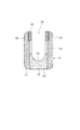
連結部材4は、チタンなどの耐蝕性を有する素材により形成されており、陽極酸化処理が施されて表面全体に被膜が形成されている。連結部材4は、図5に示すように、直立して対峙する一対の側壁部10と、この一対の側壁部10の下部を接続する底壁部11とにより断面U字状に形成されている。
The connecting
一対の側壁部10の間隔は、ロッド2の最大径よりも若干広く、スクリュー部材3の頭部8の最大径よりも若干狭く形成されている。一対の側壁部10の内面には、この頭部8を下部に導くために、幅方向中心を通り上下方向(図5における上下方向)に延びる頭部用溝14が形成されている。頭部用溝14は、頭部8が挿通されるように、頭部8の最大径より若干大きめの内径を有する円弧状の面に形成されている。そして、この頭部用溝14の上部には、一対の側壁部10内側に押圧部材6がねじ込まれる雌ネジ部15が形成されている。
The distance between the pair of
底壁部11には、スクリュー部材3が上下方向に挿通される穴23が形成されており、この穴23が設けられる底壁部11の内壁面には、スクリュー部材3の頭部8を受け、スクリュー部材3を傾動自在に支持する頭部支持部13が形成されている。
The
頭部支持部13は、上部から下端付近にかけて頭部用溝14と同径円状の内壁面を有すると共に、下端がネジ部7の最大径よりも大きく頭部8の最大径よりも小さくなるように、下端部が頭部8の外形と適合する凹曲面状に形成されている。そして、図6に示すように、頭部8を連結部材4に対して傾動自在に支持する頭部支持部13の内表面は、サンドブラスト処理されている。なお、頭部支持部13は上記の形状に限られず、ネジ部7が挿通されると共に、頭部8を連結部材4に対して傾動自在に支持できる形状であれば如何なる形状であっても良い。
The
また、一対の側壁部10により、ロッド2がスクリュー部材3と異なる方向(交差する方向)に挿入されるロッド挿入部24が形成されている。そして、底壁部11又は一対の側壁部10及び底壁部11により、頭部保持部材5の位置決めを行う位置決め部12が形成されている。
Further, the pair of
頭部保持部材5は、チタンなどの耐蝕性を有する素材により形成されており、陽極酸化処理が施されて表面全体に被膜が形成されている。頭部保持部材5は、図7に示すように、スクリュー部材3の頭部8を連結部材4に対して傾動自在に保持する頭部保持部16が設けられる円筒状の円筒部18と、円筒部18の上端部から側方に延びてロッド2を保持するロッド保持部17とが形成されている。
The
円筒部18の外形は、連結部材4の穴23にはめ込まれる大きさに形成されている。円筒部18の上部内壁面は、同径円状に形成されており、その内径は、頭部8を保持するとともに頭部8に形成された凹部9に星型レンチを差し込めるように、頭部8の最大径よりも小さく凹部9の最大径よりも大きく形成されている。そして、円筒部18の下部内壁面に頭部保持部16が形成されている。この頭部保持部16は、下端に向かうに従い内径が拡大して、頭部8を保持するために頭部8の外形と適合する凹曲面状に形成されている。そして、頭部8を保持する頭部保持部16の内表面は、サンドブラスト処理が施されている。この頭部保持部16が形成される円筒部18の下端部には、複数の切欠き20が形成されている。また、円筒部18には、下端から上方に向けてスリット19が設けられている。スリット19は円筒部18の下端から上方に向けて形成されていれば良いが、本実施例では、下端から上端までスリット19が設けられており、円筒部18の側壁部はこのスリット19により上下方向に分断されている。
The outer shape of the
ロッド保持部17は、ハーフパイプ状に形成されている。ロッド保持部17のその下面は連結部材4の位置決め部12に適合するように凸曲面状に形成されており、ロッド保持部17の上面はロッド2の外形に適合するように凹曲面状に形成されている。また、ロッド保持部17は、頭部保持部16が連結部材4の穴23にはめ込まれた状態で位置決め部12に沿うように延び、位置決め部12とほぼ同一の長さに形成されている。
The
押圧部材6は、チタンなどの耐蝕性を有する素材により形成されており、陽極酸化処理が施されて表面全体に被膜が形成されている。押圧部材6は、図2に示すように、略円柱状に形成されており、その外周面には、連結部材4に形成された雌ネジ部15にねじ込む雄ネジ部21が形成されている。押圧部材6の上面には、頭部8の凹部9と同様に、押圧部材6を回転させる星型レンチ(不図示)が差し込まれるように、押圧部材6のねじ込み方向に向けて星型に窪んだ凹部22が形成されている。
The
次に、椎骨連結部材1におけるスクリュー部材3、連結部材4、頭部保持部材5及び押圧部材6の製造方法について説明する。まず、スクリュー部材3、連結部材4、頭部保持部材5及び押圧部材6を、それぞれチタン等で形成する。そして、スクリュー部材3、連結部材4、頭部保持部材5及び押圧部材6を、それぞれ陽極酸化処理を施して表面全体に被膜を形成する。その後、スクリュー部材3の頭部8、連結部材4の頭部支持部13及び頭部保持部材5の頭部保持部16に対して、サンドブラスト処理を行う。なお、サンドブラスト処理は、スクリュー部材3の頭部8、連結部材4の頭部支持部13及び頭部保持部材5の頭部保持部16の全てに対して行ってもよく、何れか1つ、又は何れか2つに対して行っても良い。このようにして、スクリュー部材3、連結部材4、頭部保持部材5及び押圧部材6をそれぞれ製造することができる。
Next, the manufacturing method of the
次に、椎骨連結部材1の組み立て方法及び椎骨連結方法について説明する。
Next, an assembly method of the
まず、連結部材4の頭部支持部13にスクリュー部材3のネジ部7を挿通して、頭部8を頭部支持部13に対して支持させる。そして、連結部材4のロッド挿入部24から頭部保持部材5を挿入して、位置決め部12で頭部保持部材5の方向が定められて、穴23に円筒部18をはめ込み、頭部8を頭部保持部16で保持させる。これにより、図8及び図9に示すように、スクリュー部材3、連結部材4及び頭部保持部材5が一体になると共に、スクリュー部材3が連結部材4に対して傾動自在に保持される。
First, the
その後、各椎骨連結部材1の各ロッド保持部17が一直線上に配置されるように、スクリュー部材3を連結させる複数の椎骨にそれぞれねじ込む。このねじ込みは、頭部8に形成された凹部9に星型レンチを差し込み、スクリュー部材3を回すことにより行う。
Thereafter, the
その後、各連結部材4の傾き具合を補正しながら各ロッド保持部17に1本のロッド2を通し、押圧部材6を各連結部材4にねじ込む。これにより、ロッド2及びスクリュー部材3が連結部材4に対して連結固定される。そして、ロッド2に複数の椎骨連結部材1が連結固定されることにより、複数の椎骨が連結固定される。
Thereafter, one
以上説明したように、椎骨連結部材1では、頭部8、頭部支持部13及び頭部保持部16のうち少なくとも一つの表面がサンドブラスト処理されることで、頭部8と、頭部支持部13及び/又は頭部保持部16との摩擦抵抗が格段に大きくなる。このため、椎骨連結部材1によれば、押圧部材6によりロッド2及び頭部保持部材5を介して頭部8を頭部支持部13に向けて押圧することで、スクリュー部材3とロッド2とを連結する際に、連結部材4に対して頭部8を強固に固定することが可能となる。その結果、連結部材4に対する頭部8のずれを抑制することができ、確実に椎骨を連結することができる。
As described above, in the
ここで、頭部8、頭部支持部13及び頭部保持部16のうち少なくとも一つの表面サンドブラスト処理を施すことにより、簡易に粗面化処理を行うことが可能となる。
Here, by performing at least one surface sand blasting process among the
また、椎骨連結部材1では、押圧部材6によりロッド2及び頭部保持部材5を介して頭部8を頭部支持部13に向けて押圧すると、スクリュー部材3の頭部8が頭部保持部材5の円筒部18内に押し込まれる。すると、頭部保持部材5が広がるように弾性変形して、頭部保持部材5の復元力により頭部8を挟み込むように作用する。このため、頭部保持部材5と頭部8との固定をより強固にすることが可能となる。
Further, in the
また、この椎骨連結部材1では、押圧部材6によりロッド2及び頭部保持部材5を介して頭部8を頭部支持部13に向けて押圧すると、頭部保持部材5の切欠き20がスクリュー部材3の頭部8に食い込む。このため、椎骨連結部材1によれば、頭部保持部材5と頭部8との固定をより強固にすることが可能となる。
In this
また、この椎骨連結部材1によれば、頭部支持部13及び頭部保持部16を頭部8に適合する凹曲面状に形成することで、頭部8と頭部支持部13及び頭部保持部16との接触面積が大きくなるため、連結部材4に対して頭部8をより強固に固定することが可能となる。
Further, according to the
また、この椎骨連結部材1によれば、押圧部材6を連結部材4の内側にねじ込むことで、椎骨連結部材1の外形を小さくすることができ、椎骨連結部材1で連結される椎骨の周囲組織に与える負担を低減することが可能となる。
Further, according to the
なお、本実施例では、頭部8、頭部支持部13及び頭部保持部16に対して、サンドブラスト処理を行う椎骨連結部材1について説明したが、サンドブラスト処理の代わりに又はサンドブラスト処理と共に、他の粗面化処理を行う椎骨連結部材であっても良い。例えば、化学エッチング、スパッタリング等により粗面化処理を行っても良い。
In the present embodiment, the
また、図10に示す椎骨連結部材30ように、頭部8、頭部支持部13及び頭部保持部16の少なくとも一つに、滑り防止剤31や接着剤32などを塗布しても良い。この椎骨連結部材30では、頭部8と、頭部支持部13及び/又は頭部保持部16との滑りが抑制される。このため、押圧部材6によりロッド2及び頭部保持部材5を介して頭部8を頭部支持部13に向けて押圧することで、スクリュー部材3とロッド2とを連結する際に、連結部材4に対して頭部8を強固に固定することが可能となる。その結果、連結部材4に対する頭部8のずれを抑制することができ、確実に椎骨を連結することができる。
Further, as in the
また、図11に示す椎骨連結部材40のように、頭部8、頭部支持部13及び頭部保持部16の表面の少なくとも一つに、微小な突起41を設けても良い。この椎骨連結部材40では、押圧部材6によりロッド2及び頭部保持部材5を介して頭部8を頭部支持部13に向けて押圧すると、頭部8、頭部支持部13及び/又は頭部保持部16に突起41が食い込む。このため、スクリュー部材3とロッド2とを連結する際に、連結部材4に対して頭部8をより確実に固定することが可能となる。
Further, as in the
以上の本発明の説明から、本発明を様々に変形しうることは明らかである。そのような変形は、本発明の思想および範囲から逸脱するものとは認めることはできず、すべての当業者にとって自明である改良は、本発明に含まれるものである。 From the above description of the present invention, it is apparent that the present invention can be modified in various ways. Such modifications cannot be construed as departing from the spirit and scope of the present invention, and modifications obvious to all persons skilled in the art are included in the present invention.
1…椎骨連結部材、2…ロッド、3…スクリュー部材、4…連結部材、5…頭部保持部材、6…押圧部材、7…ネジ部(スクリュー部)、8…頭部,13…頭部支持部、16…頭部保持部、17…ロッド保持部、18…円筒部(環状部)、19…スリット、20…切欠き、24…ロッド挿入部、41…突起。
DESCRIPTION OF
Claims (13)
一端に設けられた球状の頭部と、前記椎骨にねじ込まれるスクリュー部とを有するスクリュー部材と、
前記スクリュー部材が挿通されると共に前記頭部を受け、前記スクリュー部材を傾動自在に支持する頭部支持部と、前記ロッドが挿入されるロッド挿入部とを有して、前記スクリュー部材と前記ロッドとを連結する連結部材と、
前記頭部を保持する頭部保持部と、前記ロッド挿入部に挿入されて前記ロッドを保持するロッド保持部とを有し、前記連結部材内において前記ロッドと前記頭部との間に挿入される頭部保持部材と、
前記ロッド及び前記頭部保持部材を介して前記頭部を前記頭部支持部に向けて押圧する押圧部材と、を備え、
前記頭部、前記頭部支持部及び前記頭部保持部のうち少なくとも一つは、表面が粗面化処理されていることを特徴とする椎骨連結部材。 A vertebra connecting member that connects a plurality of vertebrae via a rod,
A screw member having a spherical head provided at one end and a screw portion screwed into the vertebra;
The screw member is inserted into the screw member and includes a head support portion that receives the head and tiltably supports the screw member, and a rod insertion portion into which the rod is inserted. A connecting member for connecting
A head holding part that holds the head; and a rod holding part that is inserted into the rod insertion part to hold the rod, and is inserted between the rod and the head in the connecting member. A head holding member
A pressing member that presses the head toward the head support through the rod and the head holding member;
A vertebra connection member, wherein at least one of the head, the head support, and the head support has a roughened surface.
一端に設けられた球状の頭部と、前記椎骨にねじ込まれるスクリュー部とを有するスクリュー部材と、
前記スクリュー部材が挿通されると共に前記頭部を受け、前記スクリュー部材を傾動自在に支持する頭部支持部と、前記ロッドが挿入されるロッド挿入部とを有して、前記スクリュー部材と前記ロッドとを連結する連結部材と、
前記頭部を保持する頭部保持部と、前記ロッド挿入部に挿入されて前記ロッドを保持するロッド保持部とを有し、前記連結部材内において前記ロッドと前記頭部との間に挿入される頭部保持部材と、
前記ロッド及び前記頭部保持部材を介して前記頭部を前記頭部支持部に向けて押圧する押圧部材と、を備え、
前記頭部と前記頭部支持部との間及び前記頭部と前記頭部保持部との間の少なくとも一方は、表面に滑り防止剤又は接着剤が塗布されていることを特徴とする椎骨連結部材。 A vertebra connecting member that connects a plurality of vertebrae via a rod,
A screw member having a spherical head provided at one end and a screw portion screwed into the vertebra;
The screw member is inserted into the screw member and includes a head support portion that receives the head and tiltably supports the screw member, and a rod insertion portion into which the rod is inserted. A connecting member for connecting
A head holding part that holds the head; and a rod holding part that is inserted into the rod insertion part to hold the rod, and is inserted between the rod and the head in the connecting member. A head holding member
A pressing member that presses the head toward the head support through the rod and the head holding member;
An anti-slip agent or an adhesive is applied to the surface of at least one of the head and the head support part and between the head and the head holding part. Element.
The vertebra connection member according to any one of claims 8 to 12, wherein the pressing member is screwed inside the connection member.
Applications Claiming Priority (2)
| Application Number | Priority Date | Filing Date | Title |
|---|---|---|---|
| US11/584216 | 2006-10-20 | ||
| US11/584,216 US20080177324A1 (en) | 2006-10-20 | 2006-10-20 | Vertebra connection member |
Publications (2)
| Publication Number | Publication Date |
|---|---|
| JP2008100059A true JP2008100059A (en) | 2008-05-01 |
| JP5054481B2 JP5054481B2 (en) | 2012-10-24 |
Family
ID=38950786
Family Applications (1)
| Application Number | Title | Priority Date | Filing Date |
|---|---|---|---|
| JP2007257987A Active JP5054481B2 (en) | 2006-10-20 | 2007-10-01 | Vertebral connecting member |
Country Status (5)
| Country | Link |
|---|---|
| US (1) | US20080177324A1 (en) |
| EP (1) | EP1913885B1 (en) |
| JP (1) | JP5054481B2 (en) |
| KR (1) | KR20080035972A (en) |
| DE (1) | DE602007002602D1 (en) |
Cited By (1)
| Publication number | Priority date | Publication date | Assignee | Title |
|---|---|---|---|---|
| JP2017029570A (en) * | 2015-08-05 | 2017-02-09 | 裕美子 松井 | Base parts and auxiliary / reinforcement / accessory parts for sewing products, bags and containers |
Families Citing this family (10)
| Publication number | Priority date | Publication date | Assignee | Title |
|---|---|---|---|---|
| US8475495B2 (en) | 2004-04-08 | 2013-07-02 | Globus Medical | Polyaxial screw |
| US7503924B2 (en) | 2004-04-08 | 2009-03-17 | Globus Medical, Inc. | Polyaxial screw |
| US9358047B2 (en) | 2011-07-15 | 2016-06-07 | Globus Medical, Inc. | Orthopedic fixation devices and methods of installation thereof |
| US9198694B2 (en) | 2011-07-15 | 2015-12-01 | Globus Medical, Inc. | Orthopedic fixation devices and methods of installation thereof |
| US9993269B2 (en) | 2011-07-15 | 2018-06-12 | Globus Medical, Inc. | Orthopedic fixation devices and methods of installation thereof |
| US8888827B2 (en) | 2011-07-15 | 2014-11-18 | Globus Medical, Inc. | Orthopedic fixation devices and methods of installation thereof |
| US9186187B2 (en) | 2011-07-15 | 2015-11-17 | Globus Medical, Inc. | Orthopedic fixation devices and methods of installation thereof |
| WO2017180653A1 (en) | 2016-04-11 | 2017-10-19 | Osteovantage, Inc | Spinal instrumentation to enhance osteogenesis and fusion |
| US10485596B2 (en) * | 2016-12-06 | 2019-11-26 | Medos International Sàrl | Longitudinally-adjustable bone anchors and related methods |
| US9763700B1 (en) * | 2016-12-14 | 2017-09-19 | Spine Wave, Inc. | Polyaxial bone screw |
Citations (4)
| Publication number | Priority date | Publication date | Assignee | Title |
|---|---|---|---|---|
| JPH08257035A (en) * | 1995-03-15 | 1996-10-08 | Juergen Harms | Anchor component |
| JP2004097705A (en) * | 2002-09-12 | 2004-04-02 | Showa Ika Kohgyo Co Ltd | Rod part fixing structure for vertebra connecting member |
| WO2006102605A2 (en) * | 2005-03-23 | 2006-09-28 | Alphaspine, Inc. | Percutaneous pedicle screw assembly |
| US20060235392A1 (en) * | 2004-08-27 | 2006-10-19 | Hammer Michael A | Multi-axial connection system |
Family Cites Families (16)
| Publication number | Priority date | Publication date | Assignee | Title |
|---|---|---|---|---|
| DE3923996A1 (en) * | 1989-07-20 | 1991-01-31 | Lutz Biedermann | RECORDING PART FOR JOINTLY CONNECTING TO A SCREW FOR MAKING A PEDICLE SCREW |
| WO1991016020A1 (en) * | 1990-04-26 | 1991-10-31 | Danninger Medical Technology, Inc. | Transpedicular screw system and method of use |
| US6077262A (en) * | 1993-06-04 | 2000-06-20 | Synthes (U.S.A.) | Posterior spinal implant |
| US5628740A (en) * | 1993-12-23 | 1997-05-13 | Mullane; Thomas S. | Articulating toggle bolt bone screw |
| US5782833A (en) * | 1996-12-20 | 1998-07-21 | Haider; Thomas T. | Pedicle screw system for osteosynthesis |
| EP1174092A3 (en) * | 2000-07-22 | 2003-03-26 | Corin Spinal Systems Limited | A pedicle attachment assembly |
| US7862587B2 (en) * | 2004-02-27 | 2011-01-04 | Jackson Roger P | Dynamic stabilization assemblies, tool set and method |
| US6793657B2 (en) * | 2001-09-10 | 2004-09-21 | Solco Biomedical Co., Ltd. | Spine fixing apparatus |
| DE10213855A1 (en) * | 2002-03-27 | 2003-10-16 | Biedermann Motech Gmbh | Bone anchoring device for stabilizing bone segments and receiving part of a bone anchoring device |
| US6733502B2 (en) * | 2002-05-15 | 2004-05-11 | Cross Medical Products, Inc. | Variable locking spinal screw having a knurled collar |
| US7087057B2 (en) * | 2003-06-27 | 2006-08-08 | Depuy Acromed, Inc. | Polyaxial bone screw |
| US7857834B2 (en) * | 2004-06-14 | 2010-12-28 | Zimmer Spine, Inc. | Spinal implant fixation assembly |
| US7572279B2 (en) * | 2004-11-10 | 2009-08-11 | Jackson Roger P | Polyaxial bone screw with discontinuous helically wound capture connection |
| US7862588B2 (en) * | 2005-02-18 | 2011-01-04 | Samy Abdou | Devices and methods for dynamic fixation of skeletal structure |
| US7476239B2 (en) * | 2005-05-10 | 2009-01-13 | Jackson Roger P | Polyaxial bone screw with compound articulation |
| US7338491B2 (en) * | 2005-03-22 | 2008-03-04 | Spinefrontier Inc | Spinal fixation locking mechanism |
-
2006
- 2006-10-20 US US11/584,216 patent/US20080177324A1/en not_active Abandoned
-
2007
- 2007-10-01 JP JP2007257987A patent/JP5054481B2/en active Active
- 2007-10-15 DE DE602007002602T patent/DE602007002602D1/en active Active
- 2007-10-15 EP EP07020160A patent/EP1913885B1/en not_active Not-in-force
- 2007-10-18 KR KR1020070105003A patent/KR20080035972A/en not_active Withdrawn
Patent Citations (4)
| Publication number | Priority date | Publication date | Assignee | Title |
|---|---|---|---|---|
| JPH08257035A (en) * | 1995-03-15 | 1996-10-08 | Juergen Harms | Anchor component |
| JP2004097705A (en) * | 2002-09-12 | 2004-04-02 | Showa Ika Kohgyo Co Ltd | Rod part fixing structure for vertebra connecting member |
| US20060235392A1 (en) * | 2004-08-27 | 2006-10-19 | Hammer Michael A | Multi-axial connection system |
| WO2006102605A2 (en) * | 2005-03-23 | 2006-09-28 | Alphaspine, Inc. | Percutaneous pedicle screw assembly |
Cited By (1)
| Publication number | Priority date | Publication date | Assignee | Title |
|---|---|---|---|---|
| JP2017029570A (en) * | 2015-08-05 | 2017-02-09 | 裕美子 松井 | Base parts and auxiliary / reinforcement / accessory parts for sewing products, bags and containers |
Also Published As
| Publication number | Publication date |
|---|---|
| KR20080035972A (en) | 2008-04-24 |
| DE602007002602D1 (en) | 2009-11-12 |
| EP1913885A1 (en) | 2008-04-23 |
| EP1913885B1 (en) | 2009-09-30 |
| JP5054481B2 (en) | 2012-10-24 |
| US20080177324A1 (en) | 2008-07-24 |
Similar Documents
| Publication | Publication Date | Title |
|---|---|---|
| JP5054481B2 (en) | Vertebral connecting member | |
| JP5847412B2 (en) | Bone fixation device | |
| US9655652B2 (en) | Bone anchoring device | |
| JP4047112B2 (en) | Rod part fixing structure of vertebra connecting member | |
| US7572278B2 (en) | Rod connector | |
| JP6159656B2 (en) | Dynamic bone anchor and method of manufacturing a dynamic bone anchor | |
| JP6012136B2 (en) | Bone fixation device | |
| JP5043926B2 (en) | Multiaxial bone screw fitting seat | |
| US8882809B2 (en) | Pedicle screws and methods of using the same | |
| JP6076216B2 (en) | Polyaxial bone anchoring device | |
| JP6139988B2 (en) | Polyaxial bone anchoring device | |
| US20060217717A1 (en) | Methods and devices for stabilizing a bone anchor | |
| TW201509366A (en) | Polyaxial bone anchoring device | |
| JP2003232314A (en) | Rod interval retaining tool | |
| EP3437576B1 (en) | Stabilization device for bones or vertebrae | |
| US20130150904A1 (en) | Monoplanar bone anchoring device with selectable pivot plane | |
| JP2008206976A (en) | Device for stabilizing vertebrae and rod connector used therefor | |
| JP2020503988A (en) | Surgical screwdrivers and screws | |
| JP4221033B2 (en) | Vertebral connecting member and nut driver | |
| JP4221032B2 (en) | connector | |
| JP6786202B2 (en) | Implant structure for orthodontics and implant jig for orthodontics | |
| JP2013176606A (en) | Bone fixation device | |
| JP2007296083A (en) | Supporting device for vertebrae connecting member | |
| TW201350080A (en) | Polyaxial bone anchoring device | |
| JPWO2007108227A1 (en) | Abutment |
Legal Events
| Date | Code | Title | Description |
|---|---|---|---|
| A621 | Written request for application examination |
Free format text: JAPANESE INTERMEDIATE CODE: A621 Effective date: 20100809 |
|
| A977 | Report on retrieval |
Free format text: JAPANESE INTERMEDIATE CODE: A971007 Effective date: 20120412 |
|
| A131 | Notification of reasons for refusal |
Free format text: JAPANESE INTERMEDIATE CODE: A131 Effective date: 20120417 |
|
| A521 | Request for written amendment filed |
Free format text: JAPANESE INTERMEDIATE CODE: A523 Effective date: 20120614 |
|
| TRDD | Decision of grant or rejection written | ||
| A01 | Written decision to grant a patent or to grant a registration (utility model) |
Free format text: JAPANESE INTERMEDIATE CODE: A01 Effective date: 20120724 |
|
| A01 | Written decision to grant a patent or to grant a registration (utility model) |
Free format text: JAPANESE INTERMEDIATE CODE: A01 |
|
| A61 | First payment of annual fees (during grant procedure) |
Free format text: JAPANESE INTERMEDIATE CODE: A61 Effective date: 20120727 |
|
| R150 | Certificate of patent or registration of utility model |
Ref document number: 5054481 Country of ref document: JP Free format text: JAPANESE INTERMEDIATE CODE: R150 Free format text: JAPANESE INTERMEDIATE CODE: R150 |
|
| FPAY | Renewal fee payment (event date is renewal date of database) |
Free format text: PAYMENT UNTIL: 20150803 Year of fee payment: 3 |
|
| R250 | Receipt of annual fees |
Free format text: JAPANESE INTERMEDIATE CODE: R250 |
|
| R250 | Receipt of annual fees |
Free format text: JAPANESE INTERMEDIATE CODE: R250 |
|
| S111 | Request for change of ownership or part of ownership |
Free format text: JAPANESE INTERMEDIATE CODE: R313113 |
|
| R350 | Written notification of registration of transfer |
Free format text: JAPANESE INTERMEDIATE CODE: R350 |
|
| S111 | Request for change of ownership or part of ownership |
Free format text: JAPANESE INTERMEDIATE CODE: R313113 |
|
| S111 | Request for change of ownership or part of ownership |
Free format text: JAPANESE INTERMEDIATE CODE: R313113 |
|
| R350 | Written notification of registration of transfer |
Free format text: JAPANESE INTERMEDIATE CODE: R350 |
|
| R350 | Written notification of registration of transfer |
Free format text: JAPANESE INTERMEDIATE CODE: R350 |
|
| R250 | Receipt of annual fees |
Free format text: JAPANESE INTERMEDIATE CODE: R250 |
|
| S111 | Request for change of ownership or part of ownership |
Free format text: JAPANESE INTERMEDIATE CODE: R313113 |
|
| R350 | Written notification of registration of transfer |
Free format text: JAPANESE INTERMEDIATE CODE: R350 |
|
| R250 | Receipt of annual fees |
Free format text: JAPANESE INTERMEDIATE CODE: R250 |
|
| R250 | Receipt of annual fees |
Free format text: JAPANESE INTERMEDIATE CODE: R250 |
|
| R250 | Receipt of annual fees |
Free format text: JAPANESE INTERMEDIATE CODE: R250 |
|
| S533 | Written request for registration of change of name |
Free format text: JAPANESE INTERMEDIATE CODE: R313533 |
|
| R350 | Written notification of registration of transfer |
Free format text: JAPANESE INTERMEDIATE CODE: R350 |