JP2008072447A - Image distribution system, image distribution program, and image distribution method - Google Patents
Image distribution system, image distribution program, and image distribution method Download PDFInfo
- Publication number
- JP2008072447A JP2008072447A JP2006249252A JP2006249252A JP2008072447A JP 2008072447 A JP2008072447 A JP 2008072447A JP 2006249252 A JP2006249252 A JP 2006249252A JP 2006249252 A JP2006249252 A JP 2006249252A JP 2008072447 A JP2008072447 A JP 2008072447A
- Authority
- JP
- Japan
- Prior art keywords
- image
- distribution
- monitor
- monitoring
- unit
- Prior art date
- Legal status (The legal status is an assumption and is not a legal conclusion. Google has not performed a legal analysis and makes no representation as to the accuracy of the status listed.)
- Withdrawn
Links
Images


Classifications
-
- H—ELECTRICITY
- H04—ELECTRIC COMMUNICATION TECHNIQUE
- H04N—PICTORIAL COMMUNICATION, e.g. TELEVISION
- H04N7/00—Television systems
- H04N7/18—Closed-circuit television [CCTV] systems, i.e. systems in which the video signal is not broadcast
- H04N7/183—Closed-circuit television [CCTV] systems, i.e. systems in which the video signal is not broadcast for receiving images from a single remote source
Landscapes
- Engineering & Computer Science (AREA)
- Multimedia (AREA)
- Signal Processing (AREA)
- Closed-Circuit Television Systems (AREA)
Abstract
【課題】画像の監視状態に応じて画像の配信を行うことができる画像配信システム、画像配信プログラム、画像配信方法を提供する。
【解決手段】少なくとも1つのモニタへ画像の配信を行う画像配信システムであって、モニタに表示するための少なくとも1つの画像を取得する画像取得部と、モニタ毎の監視状態を取得する状態取得部と、状態取得部により取得された監視状態に基づいてモニタから配信先とするモニタを選択し、画像取得部により取得された画像から配信先とするモニタ毎に配信する画像である配信画像を選択し、該配信画像を対応する配信先へ配信する配信部とを備えた。
【選択図】図1An image distribution system, an image distribution program, and an image distribution method capable of distributing an image according to an image monitoring state are provided.
An image distribution system that distributes an image to at least one monitor, an image acquisition unit that acquires at least one image to be displayed on the monitor, and a state acquisition unit that acquires a monitoring state for each monitor Then, based on the monitoring status acquired by the status acquisition unit, select a monitor as a distribution destination from the monitor, and select a distribution image that is an image distributed to each monitor as a distribution destination from the image acquired by the image acquisition unit And a distribution unit that distributes the distribution image to a corresponding distribution destination.
[Selection] Figure 1
Description
本発明は、モニタに表示する画像の配信を行う画像配信システムに関するものである。 The present invention relates to an image distribution system that distributes an image to be displayed on a monitor.
従来から、異常事態の早期発見のため、人(監視員)が監視カメラの画像を監視するという業務が行われている。しかし、監視員が1人で監視を行う場合の欠点として、離席・よそ見・意識の低下などにより、画像を見ず、監視が行われない場合が発生することが挙げられる。 Conventionally, in order to detect an abnormal situation at an early stage, a person (monitor) monitors an image of a monitoring camera. However, a disadvantage of monitoring by a single monitor is that there are cases where monitoring is not performed without looking at an image due to absence from the desk, looking away, or a decrease in consciousness.
その問題を解決するために、従来は次の2つの方法が用いられている。 In order to solve this problem, the following two methods are conventionally used.
第1の方法として、監視員が1人であっても、監視員の意識を監視に集中させるための方法がある。これは、監視員が正常に監視業務を行っているか否かを定期的に確認することにより、正常でない場合に、正常に監視を再開するように促す方法である。具体的な例として、特許文献1の方法は、あらかじめ設定した時間に監視員にデータ入力を促し、データ入力の有無および入力されたデータの正常性を判断して、監視員が正常に監視業務を行っているかどうかを判断する。正常に監視業務を行っていないと判断した場合は、監視員が再び監視することを促すために警報を発する。 As a first method, there is a method for concentrating the consciousness of the monitor on the monitoring even if there is only one monitor. This is a method for promptly resuming the monitoring if it is not normal by periodically checking whether or not the monitoring person is normally performing the monitoring work. As a specific example, the method of Patent Document 1 prompts a monitor to input data at a preset time, determines whether or not data is input and the normality of the input data, and allows the monitor to perform normal monitoring work. Determine whether you are doing. If it is determined that the monitoring operation is not normally performed, an alarm is issued to urge the monitor to monitor again.
第2の方法として、交代用の監視員を用意する方法がある。これは、複数の監視員が同一の部屋で監視を行うことにより、監視員の離席などで監視されなくなった画像は他の監視員が監視する方法である。これは、集中監視システムと呼ばれ、一般的に行われている。
上述した第1の方法は、警報を発することで、監視員に監視を再開するように促すが、監視を再開できない状況が続く場合には、誰も画像を監視していない状況になってしまい、監視漏れが発生する。そのため、第1の方法で1人による監視はそもそも不可能であり、複数人の監視員を用意し、バックアップできる第2の方法を採る必要がある。 In the first method described above, an alarm is issued to prompt the monitor to resume monitoring. However, if the situation in which monitoring cannot be resumed continues, no one is monitoring the image. Monitoring omission occurs. Therefore, the first method cannot be monitored by one person in the first place, and it is necessary to prepare a second person who can prepare and back up a plurality of observers.
しかしながら、第2の方法における監視員の最適配置について、次に説明するような課題がある。平成14年4月5日厚生労働省発表の「VDT(Visual Display Terminals)作業(VDT作業機器を使用して、監視等を行う作業)における労働衛生管理のためのガイドライン」によると、VDT作業を行う場合に次のような作業管理を行うよう指示している。 However, there is a problem as described below with regard to the optimal arrangement of the monitoring personnel in the second method. According to the "GDT Guidelines for Occupational Health Management in VDT (Visual Display Terminals) work (work using VDT work equipment)" announced by the Ministry of Health, Labor and Welfare on April 5, 2002. In this case, the following work management is instructed.
・一連続作業時間:1時間を超えないようにすること。
・作業休止時間:連続作業と連続作業の間に10〜15分の作業休止時間を設けること。
・ One continuous work time: Do not exceed one hour.
-Work downtime: Provide a work downtime of 10 to 15 minutes between continuous work.
また、労働基準法の第四章第三十四条では「使用者は、労働時間が六時間を超える場合においては少なくとも四十五分、八時間を超える場合においては少なくとも一時間の休憩時間を労働時間の途中に与えなければならない。」と定められている。
Also,
このガイドラインと法律を元に無駄の無い配置を試算したところ、六時間の四交代制にした場合は、監視員6人分の監視画像に対して7人の監視員が交代で監視を行う必要がある。また、二十四時間監視の一般的なローテーションである八時間の三交代制にした場合は、監視員72人分の監視画像に対して91人の監視員が交代で監視を行う必要がある。 Based on this guideline and law, we calculated a wasteful arrangement, and in the case of a six-hour four-shift system, it is necessary for seven surveillance personnel to monitor the surveillance image for six surveillance personnel. There is. In addition, in the case of the eight-hour three-shift system, which is a general rotation for twenty-four-hour monitoring, it is necessary for 91 monitoring personnel to monitor the monitoring images for 72 monitoring personnel in turn. .
今後、監視カメラへの期待が高まり、監視カメラが増えて、監視員を増やす必要が出てきた場合に、既存のスペースを利用できるというメリットを活かし、建物毎の警備員室や個人の自宅などの小規模なスペースで監視を行う需要が高まると考えられる。そのため、1箇所に従来より少ない人数しか配置できない場合でも、効率的に監視を行うことが求められる。しかしながら、1箇所の人数を従来の最適配置の人数より少なくしようとすると、監視員が冗長となる時間が発生し、非効率的であるという課題がある。 In the future, when expectations for surveillance cameras increase, the number of surveillance cameras increases, and there is a need to increase the number of surveillance personnel, taking advantage of the ability to use existing space, security room for each building, private home, etc. The demand for monitoring in a small space is expected to increase. For this reason, even when a smaller number of persons can be arranged in one place, it is required to perform monitoring efficiently. However, if the number of people in one place is made smaller than the number of people in the conventional optimum arrangement, there will be a problem that the time for monitoring personnel becomes redundant and inefficient.
例えば、監視員2人分の画像を3人の監視員で監視している監視室が3箇所あり、六時間の四交代制を行う場合を考える。3箇所合わせると、画像は6人分で、監視員が9人いることが分かる。しかし、画像の数のみで計算すると、監視員は上述したように7人で最適となるため、2人が冗長であることがわかる。このような場合において、3箇所の監視室を1箇所に統合することができれば良いが、物理的・地理的な問題等により最適配置を行うことは困難である。 For example, let us consider a case where there are three monitoring rooms where images of two monitoring personnel are monitored by three monitoring personnel and a four-hour shift system of six hours is performed. When the three places are combined, it can be seen that there are 6 images and 9 observers. However, if only the number of images is used for calculation, the number of monitoring personnel is optimal for seven persons as described above, and it can be seen that two persons are redundant. In such a case, it is sufficient that the three monitoring rooms can be integrated into one place, but it is difficult to optimally arrange due to physical and geographical problems.
本発明は上述した問題点を解決するためになされたものであり、画像の監視状態に応じて画像の配信を行うことができる画像配信システム、画像配信プログラム、画像配信方法を提供することを目的とする。 SUMMARY An advantage of some aspects of the invention is that it provides an image distribution system, an image distribution program, and an image distribution method capable of distributing an image according to an image monitoring state. And
上述した課題を解決するため、本発明は、少なくとも1つのモニタへ画像の配信を行う画像配信システムであって、前記モニタに表示するための少なくとも1つの画像を取得する画像取得部と、前記モニタ毎の監視状態を取得する状態取得部と、前記状態取得部により取得された監視状態に基づいて前記モニタの中から配信先とするモニタを選択し、前記画像取得部により取得された画像から前記配信先とするモニタ毎に配信する画像である配信画像を選択し、該配信画像を対応する前記配信先へ配信する配信部とを備えたものである。 In order to solve the above-described problems, the present invention provides an image distribution system that distributes an image to at least one monitor, the image acquisition unit acquiring at least one image to be displayed on the monitor, and the monitor A state acquisition unit for acquiring each monitoring state, and a monitor to be a delivery destination is selected from the monitors based on the monitoring state acquired by the state acquisition unit, and the image acquired by the image acquisition unit A distribution unit that selects a distribution image that is an image to be distributed to each monitor as a distribution destination and distributes the distribution image to the corresponding distribution destination.
また、本発明に係る画像配信システムにおいて、前記配信部は、前記監視状態が正常であるモニタを正常モニタとし、該正常モニタを前記配信先のモニタとすることを特徴とする。 Also, in the image distribution system according to the present invention, the distribution unit is characterized in that the monitor in which the monitoring state is normal is a normal monitor, and the normal monitor is the monitor of the distribution destination.
また、本発明に係る画像配信システムにおいて、前記配信部は、前記画像取得部により取得された画像を前記配信先とするモニタへ分配し、該分配結果を前記配信先とするモニタ毎の配信画像として更新することを特徴とする。 In the image distribution system according to the present invention, the distribution unit distributes the image acquired by the image acquisition unit to the monitor as the distribution destination, and the distribution image for each monitor as the distribution destination. It is characterized by updating as follows.
また、本発明に係る画像配信システムにおいて、前記画像取得部は更に、取得した画像の撮影元を示す撮影元識別子を取得し、更に、前記モニタが表示すべき画像である標準画像について、予め設定された前記モニタ毎の前記標準画像の撮影元識別子を取得する標準情報取得部を備え、前記配信部は、前記正常モニタ以外のモニタを異常モニタとし、前記画像取得部により取得された撮影元識別子と前記標準情報取得部により取得された撮影元識別子とに基づいて、前記正常モニタに対応する標準画像を前記正常モニタへの配信画像とすると共に、前記異常モニタに対応する標準画像を前記正常モニタへ配信することを特徴とする。 In the image distribution system according to the present invention, the image acquisition unit further acquires a shooting source identifier indicating a shooting source of the acquired image, and further sets in advance a standard image that is an image to be displayed on the monitor. A standard information acquisition unit that acquires an imaging source identifier of the standard image for each of the monitors that has been used, and the distribution unit sets a monitor other than the normal monitor as an abnormal monitor, and the imaging source identifier acquired by the image acquisition unit And a standard image corresponding to the normal monitor as a distribution image to the normal monitor based on the photographing source identifier acquired by the standard information acquisition unit and the normal image corresponding to the abnormal monitor as the normal monitor It is characterized by being delivered to.
また、本発明に係る画像配信システムにおいて、前記配信部は、特定の配信先のモニタに対して複数の配信画像が選択された場合、該複数の配信画像を合成して配信画像とし、該配信画像を前記特定の配信先のモニタへ配信することを特徴とする。 In the image distribution system according to the present invention, when a plurality of distribution images are selected for a specific distribution destination monitor, the distribution unit combines the plurality of distribution images into a distribution image, and the distribution unit The image is distributed to the monitor of the specific distribution destination.
また、本発明に係る画像配信システムにおいて、前記配信部は、特定の配信先のモニタに対して複数の配信画像が選択された場合、該複数の配信画像と該画像に関する情報である配信情報とを前記特定の配信先へ配信し、更に、前記配信部により配信された複数の配信画像と配信情報を受信し、前記配信情報に基づいて前記複数の配信画像を合成して1つの表示画像とし、前記特定の配信先におけるモニタに前記表示画像を表示させる表示制御部を備えることを特徴とする。 In the image distribution system according to the present invention, when a plurality of distribution images are selected for a monitor at a specific distribution destination, the distribution unit includes the plurality of distribution images and distribution information that is information related to the images. Is distributed to the specific distribution destination, further receives a plurality of distribution images and distribution information distributed by the distribution unit, and combines the plurality of distribution images based on the distribution information into one display image. And a display control unit that displays the display image on a monitor at the specific distribution destination.
また、本発明に係る画像配信システムにおいて、前記配信情報は、前記特定の配信先に配信される複数の配信画像の数を含むことを特徴とする。 In the image distribution system according to the present invention, the distribution information includes the number of a plurality of distribution images distributed to the specific distribution destination.
また、本発明に係る画像配信システムにおいて、前記配信情報は、前記特定の配信先に配信される複数の配信画像について、該配信画像の表示時の配置の情報を含むことを特徴とする。 Also, in the image distribution system according to the present invention, the distribution information includes, for a plurality of distribution images distributed to the specific distribution destination, information on an arrangement at the time of displaying the distribution image.
また、本発明に係る画像配信システムにおいて、更に、前記モニタ毎に設けられ、該モニタの監視状態を検出し、前記状態取得部へ出力する状態検出部を備えることを特徴とする。 The image distribution system according to the present invention further includes a state detection unit that is provided for each monitor, detects a monitoring state of the monitor, and outputs the state to the state acquisition unit.
また、本発明に係る画像配信システムにおいて、前記状態検出部は、前記モニタの監視者からの入力を前記監視状態として前記状態取得部へ出力することを特徴とする。 In the image distribution system according to the present invention, the state detection unit outputs an input from a monitor supervisor as the monitoring state to the state acquisition unit.
また、本発明に係る画像配信システムにおいて、前記状態検出部は、前記モニタの環境の検出を行い、該検出結果を出力し、更に、前記状態検出部による検出結果に基づいて監視者が前記モニタを正常に監視しているか否かを判別し、前記監視状態として前記状態取得部へ出力する状態判別部を備えることを特徴とする。 Further, in the image distribution system according to the present invention, the state detection unit detects the environment of the monitor, outputs the detection result, and further, the monitor performs the monitoring based on the detection result by the state detection unit. It is characterized by including a state determination unit that determines whether or not the state is normally monitored and outputs the state as the monitoring state to the state acquisition unit.
また、本発明に係る画像配信システムにおいて、前記状態検出部は、撮影を行うものであり、前記モニタを監視している時の監視者を撮影できるように設置され、撮影結果を検出結果として前記状態判別部へ出力することを特徴とする。 Further, in the image delivery system according to the present invention, the state detection unit is configured to perform imaging, and is installed so as to be able to capture a monitor when monitoring the monitor, and the imaging result is used as the detection result. It outputs to a state discrimination | determination part, It is characterized by the above-mentioned.
また、本発明に係る画像配信システムにおいて、前記状態判別部は、前記状態検出部による撮影結果から、前記監視者の有無、前記監視者の顔の向き、前記監視者の目が閉じている時間、の少なくともいずれかの抽出を行い、該抽出結果が所定の条件を満たす場合、前記監視状態を正常とすることを特徴とする。 Further, in the image distribution system according to the present invention, the state determination unit determines whether or not the monitor is present, the face of the monitor, and the time when the monitor's eyes are closed, based on a result of photographing by the state detection unit. When the extraction result satisfies a predetermined condition, the monitoring state is made normal.
また、本発明に係る画像配信システムにおいて、更に、監視対象の撮影を行い、該撮影により得られた画像を前記画像取得部へ出力する撮像部を備えることを特徴とする。 The image distribution system according to the present invention further includes an imaging unit that performs imaging of a monitoring target and outputs an image obtained by the imaging to the image acquisition unit.
また、本発明に係る画像配信システムにおいて、更に、前記モニタ毎に設けられ、前記モニタの監視者による通報の入力を受け付ける通報入力部を備えることを特徴とする。 The image distribution system according to the present invention further includes a notification input unit that is provided for each monitor and receives a notification input by a monitor of the monitor.
また、本発明に係る画像配信システムにおいて、前記配信部は、前記監視状態が変化する度に、前記配信先及び前記配信画像の選択を行うことを特徴とする。 In the image distribution system according to the present invention, the distribution unit selects the distribution destination and the distribution image every time the monitoring state changes.
また、本発明は、モニタに表示する画像の配信をコンピュータに実行させる画像配信プログラムであって、前記モニタに表示するための少なくとも1つの画像を取得する画像取得ステップと、前記モニタ毎の監視状態を取得する状態取得ステップと、前記状態取得ステップにより取得された監視状態に基づいて前記モニタの中から配信先とするモニタを選択し、前記画像取得ステップにより取得された画像から前記配信先とするモニタ毎に配信する画像である配信画像を選択し、該配信画像を対応する前記配信先へ配信する配信ステップとをコンピュータに実行させるものである。 The present invention also provides an image distribution program for causing a computer to distribute an image to be displayed on a monitor, the image acquiring step for acquiring at least one image to be displayed on the monitor, and a monitoring state for each monitor And acquiring a distribution destination from the monitors based on the monitoring state acquired by the state acquisition step, and selecting the distribution destination from the image acquired by the image acquisition step. A distribution image that is an image to be distributed for each monitor is selected, and a distribution step of distributing the distribution image to the corresponding distribution destination is executed by a computer.
また、本発明に係る画像配信プログラムにおいて、前記配信ステップは、前記監視状態が正常であるモニタを正常モニタとし、該正常モニタを前記配信先のモニタとすることを特徴とする。 Further, in the image distribution program according to the present invention, the distribution step is characterized in that a monitor in which the monitoring state is normal is a normal monitor, and the normal monitor is a monitor of the distribution destination.
また、本発明に係る画像配信プログラムにおいて、前記配信ステップは、前記画像取得ステップにより取得された画像を前記配信先とするモニタへ分配し、該分配結果を前記配信元毎の配信画像とすることを特徴とする。 In the image distribution program according to the present invention, the distribution step distributes the image acquired in the image acquisition step to the monitor as the distribution destination, and sets the distribution result as a distribution image for each distribution source. It is characterized by.
また、本発明は、モニタに表示する画像の配信を行う画像配信方法であって、前記モニタに表示するための少なくとも1つの画像を取得する画像取得ステップと、前記モニタ毎の監視状態を取得する状態取得ステップと、前記状態取得ステップにより取得された監視状態に基づいて前記モニタの中から配信先とするモニタを選択し、前記画像取得ステップにより取得された画像から前記配信先とするモニタ毎に配信する画像である配信画像を選択し、該配信画像を対応する前記配信先へ配信する配信ステップとを実行するものである。 The present invention is also an image distribution method for distributing an image to be displayed on a monitor, an image acquisition step for acquiring at least one image to be displayed on the monitor, and a monitoring state for each monitor. A monitor to be a delivery destination is selected from the monitors based on the status acquisition step and the monitoring state acquired by the status acquisition step, and each monitor to be the delivery destination is selected from the image acquired by the image acquisition step. A distribution image that is an image to be distributed is selected, and a distribution step of distributing the distribution image to the corresponding distribution destination is executed.
本発明によれば、モニタによる監視状態に応じて画像の配信を行うことができる。 According to the present invention, it is possible to distribute an image according to a monitoring state by a monitor.
以下、本発明の実施の形態について図面を参照しつつ説明する。 Embodiments of the present invention will be described below with reference to the drawings.
実施の形態1.
本実施の形態においては、監視の停止及び再開が監視員により入力され、画像の合成が表示側で行われる画像配信システムについて説明する。
Embodiment 1 FIG.
In the present embodiment, an image distribution system will be described in which monitoring stop and restart are input by a monitor and image composition is performed on the display side.
まず、本実施の形態に係る画像配信システムの構成について説明する。 First, the configuration of the image distribution system according to the present embodiment will be described.
図1は、本実施の形態に係る画像配信システムの構成の一例を示すブロック図である。この画像配信システムは、センターシステム101、複数のカメラ102、複数の監視装置103で構成される。また、センターシステム101と複数のカメラ102は、ネットワーク104で接続されている。また、センターシステム101と複数の監視装置103は、ネットワーク105で接続されている。センターシステム101は、画像振り分け部11、監視員情報管理部12、通報部13で構成される。監視装置103は、表示部31、監視状態入力部32、通報入力部33で構成される。ネットワーク104とネットワーク105は、同一のネットワークであっても良い。
FIG. 1 is a block diagram illustrating an example of a configuration of an image distribution system according to the present embodiment. This image distribution system includes a center system 101, a plurality of
次に、本実施の形態に係る画像配信システムの動作について説明する。 Next, the operation of the image distribution system according to the present embodiment will be described.
カメラ102は、撮影した画像を画像振り分け部11へ送信する。カメラ102から送信される各画像には、その画像を撮影したカメラ102を示す番号である画像番号が付加される。
The
監視状態入力部32及び通報入力部33は、例えばボタンである。休憩の開始時など、監視員が監視を停止する場合、監視員は、監視状態入力部32のボタンを押す。また、休憩の終了時など、監視員が監視を再開する場合、監視員は、監視状態入力部32のボタンを押す。このボタンが押されると、監視状態入力部32は、監視員の監視状態が変化したことを示す状態情報を監視員情報管理部12へ送信する。また、緊急時など、現場や警備員などへの通報が必要である場合、監視員は、通報入力部33のボタンを押す。このボタンが押されると、通報入力部33は、通報が必要であることを示す通報情報を通報部13へ送信する。
The monitoring state input unit 32 and the notification input unit 33 are buttons, for example. When the monitoring person stops monitoring, such as at the start of a break, the monitoring person presses the button of the monitoring state input unit 32. When the monitor resumes monitoring, such as at the end of a break, the monitor presses the button of the monitoring state input unit 32. When this button is pressed, the monitoring status input unit 32 transmits status information indicating that the monitoring status of the monitor has changed to the monitor
なお、監視状態入力部32及び通報入力部33は、表示部31に表示されたユーザインタフェースであっても良い。
The monitoring state input unit 32 and the report input unit 33 may be a user interface displayed on the
監視員情報管理部12は、監視状態リストと配信画像リストを保持する。図2は、本実施の形態に係る監視状態リストの一例を示す表である。監視状態リストは、監視員毎の監視状態として「可」(監視可能)または「不可」(監視不可能)の値を保持するものであり、画像振り分け部11に提供される。また、監視状態リストにおける「可」と「不可」の値は、対応する監視状態入力部32からの状態情報を受信する度に(監視状態入力部32のボタンが押される度に)切り替わる。図3は、本実施の形態に係る配信画像リストの一例を示す表である。配信画像リストは、監視員毎に配信する画像である配信画像の画像番号を保持するものであり、画像振り分け部11により更新される。
The monitor
通報入力部33から通報情報を受信した通報部13は、現場や警備員などへの通報を行う。 The reporting unit 13 that has received the reporting information from the reporting input unit 33 reports to the site or security guards.
次に、画像振り分け部11による配信処理の動作について説明する。配信処理には、表示部31に表示される複数の画像の合成を監視装置103で行う場合の第1配信処理と、その合成をセンターシステム101で行う場合の第2配信処理とがある。
Next, the operation of distribution processing by the image distribution unit 11 will be described. The distribution process includes a first distribution process when a plurality of images displayed on the
まず、第1配信処理について説明する。 First, the first distribution process will be described.
図4は、本実施の形態に係る第1配信処理の動作の一例を示すフローチャートである。まず、画像振り分け部11は、カメラ102から画像を受信する(S11)。受信した画像には、カメラ102毎の画像番号が付加されている。また、受信した画像の数を、監視対象画像数とする。次に、画像振り分け部11は、監視員情報管理部12における監視状態リストに基づいて、監視可能な監視員に画像を振り分ける振り分け処理を行い、その結果を配信画像リストとして監視員情報管理部12へ渡す(S12)。次に、画像振り分け部11は、監視員毎に、配信する画像の数を含む配信情報を表示部31へ送信し(S13)、振り分けられた画像を送信し(S14)、このフローは終了する。以後、このフローは繰り返し実行される。
FIG. 4 is a flowchart showing an example of the operation of the first distribution process according to the present embodiment. First, the image sorting unit 11 receives an image from the camera 102 (S11). An image number for each
画像振り分け部11からの配信情報及び画像を受信した表示部31は、配信情報における画像の数に基づいて画像を配置し、表示する。ここで、表示部31は、画像の数に従って最適な画像の表示サイズと配置を決定し、配置する。例えば、画像を行列として配置する場合、配信情報は、画像番号と行列サイズと行列における要素番号である。なお、画像振り分け部11が画像の配置を決定し、配信情報として表示部31へ送信し、表示部31が配信情報に従って画像の配置を行うようにしても良い。
The
次に、第2配信処理について説明する。 Next, the second distribution process will be described.
図5は、本実施の形態に係る第2配信処理の動作の一例を示すフローチャートである。この図において、図4と同一符号は図4に示された対象と同一又は相当処理を示しており、ここでの説明を省略する。まず、処理S11〜S12は、第1配信処理と同様である。次に、画像振り分け部11は、配信先毎に、配信する画像の合成を行い、その結果を合成画像とし(S15)、合成画像を各監視装置103へ送信し(S16)、このフローは終了する。以後、このフローは繰り返し実行される。 FIG. 5 is a flowchart showing an example of the operation of the second distribution process according to the present embodiment. In this figure, the same reference numerals as those in FIG. 4 denote the same or corresponding processes as those in FIG. 4, and description thereof will be omitted here. First, the processes S11 to S12 are the same as the first distribution process. Next, the image distribution unit 11 combines the images to be distributed for each distribution destination, sets the result as a combined image (S15), transmits the combined image to each monitoring device 103 (S16), and ends this flow. To do. Thereafter, this flow is repeatedly executed.
画像振り分け部11からの合成画像を受信した表示部31は、合成画像を表示する。
The
なお、本実施の形態においては、画像振り分け部11は、振り分け処理を繰り返すとしたが、監視状態入力部32からの状態情報を受信した場合に振り分け処理を行うようにしても良い。 In the present embodiment, the image distribution unit 11 repeats the distribution process. However, the distribution process may be performed when status information from the monitoring state input unit 32 is received.
次に、上述した振り分け処理の動作について説明する。振り分け処理には、監視員に振り分けられる画像が予め決められていない場合の第1振り分け処理と予め決められている場合の第2振り分け処理がある。 Next, the operation of the above-described distribution process will be described. The distribution process includes a first distribution process when an image to be distributed to the monitoring staff is not determined in advance and a second distribution process when the image is determined in advance.
まず、第1振り分け処理について説明する。 First, the first distribution process will be described.
図6は、本実施の形態に係る第1振り分け処理の動作の一例を示すフローチャートである。まず、画像振り分け部11は、監視可監視員数と振り分け済み画像番号の初期化を行う(S21)。監視可監視員数は、監視状態が「可」である監視員の数であり、ここでは0に初期化される。振り分け済み画像番号は、最後に振り分けた画像番号であり、ここでは0に初期化される。 FIG. 6 is a flowchart showing an example of the operation of the first distribution process according to the present embodiment. First, the image distribution unit 11 initializes the number of monitorable monitoring personnel and the allocated image number (S21). The number of monitorable monitoring personnel is the number of monitoring personnel whose monitoring status is “permitted”, and is initialized to 0 here. The assigned image number is the image number assigned last, and is initialized to 0 here.
次に、画像振り分け部11は、監視状態リストから監視可監視員数を算出する(S22)。ここで、画像振り分け部11は、監視状態リストから1レコード(1監視員)ずつ、監視状態を読み出し、監視状態が「可」である場合に監視可監視員数をインクリメントする。従って、画像振り分け部11が監視状態リストを全て読み出した時点で、監視可監視員数が設定される。 Next, the image distribution unit 11 calculates the number of monitorable persons from the monitoring state list (S22). Here, the image distribution unit 11 reads out the monitoring status for each record (1 monitoring personnel) from the monitoring status list, and increments the number of monitoring possible monitoring personnel when the monitoring status is “permitted”. Accordingly, when the image distribution unit 11 reads all the monitoring status lists, the number of monitoring-enabled monitoring personnel is set.
次に、画像振り分け部11は、振り分け前処理を行う(S23)。振り分け前処理は、次式を用いて、最少画像数と余り画像数を算出する。ここで、最少画像数は、小数点以下が切り捨てられ、整数となる。 Next, the image distribution unit 11 performs pre-distribution processing (S23). In the pre-distribution process, the minimum number of images and the number of remaining images are calculated using the following equations. Here, the minimum number of images becomes an integer by rounding off the decimal part.
最少画像数=監視対象画像数/監視可監視員数
余り画像数=監視対象画像数−最少画像数×監視可監視員数
Minimum number of images = Number of images to be monitored / Number of monitorable surpluses Number of remaining images = Number of images to be monitored−Minimum number of images × Number of monitorable monitors
次に、画像振り分け部11は、監視状態リストから1レコード(1監視員)ずつ、監視状態の読み出しを行い(S24)、監視状態リストの読み出しが終了したか否かの判断を行い、終了した場合(S31,Yes)、このフローは終了し、終了していない場合(S31,No)、次の処理へ移行する。ここで、読み出したレコードに対応する監視員を対象監視員とする。 Next, the image distribution unit 11 reads out the monitoring state for each record (one monitor) from the monitoring state list (S24), determines whether the reading of the monitoring state list is finished, and finishes. If yes (S31, Yes), this flow ends. If not (S31, No), the process proceeds to the next process. Here, the monitor corresponding to the read record is the target monitor.
次に、画像振り分け部11は、対象監視員の監視状態が「可」であるか否かの判断を行い、「不可」である場合(S32,No)、対象監視員への振り分けを行わず(S39)、処理S24へ戻り、「可」である場合(S32,Yes)、次の処理へ移行する。次に、画像振り分け部11は、余り画像数が0より大きいか否かの判断を行い、0である場合(S33,No)、処理S34へ移行し、0より大きい場合(S33,Yes)、処理S36へ移行する。 Next, the image distribution unit 11 determines whether or not the monitoring state of the target monitor is “enabled”. If it is “disabled” (S32, No), the image distributing unit 11 does not distribute to the target monitor. (S39), the process returns to the process S24, and if “Yes” (S32, Yes), the process proceeds to the next process. Next, the image distribution unit 11 determines whether or not the number of remaining images is greater than 0. If it is 0 (S33, No), the process proceeds to step S34. If it is greater than 0 (S33, Yes), Control goes to step S36.
処理S33がNoである場合、画像振り分け部11は、対象監視員への画像の振り分けを行う(S34)。ここで、(振り分け済み画像番号+1)から(振り分け済み画像番号+最少画像数)までの画像番号を持つ画像が、対象監視員へ振り分けられる。次に、画像振り分け部11は、振り分け済み画像番号の更新を行い(S35)、処理S24へ戻る。ここで、振り分け済み画像番号は、最後に振り分けられた画像番号である(振り分け済み画像番号+最少画像数)となる。 If the process S33 is No, the image distribution unit 11 distributes the image to the target monitor (S34). Here, images having image numbers from (assigned image number + 1) to (assigned image number + minimum number of images) are assigned to the target supervisor. Next, the image distribution unit 11 updates the distributed image number (S35), and returns to the process S24. Here, the assigned image number is the image number assigned last (assigned image number + minimum number of images).
処理S33がYesである場合、画像振り分け部11は、対象監視員への画像の振り分けを行う(S36)。ここで、(振り分け済み画像番号+1)から(振り分け済み画像番号+最少画像数+1)までの画像番号を持つ画像が、対象監視員へ振り分けられる。次に、画像振り分け部11は、振り分け済み画像番号及び余り画像数の更新を行い(S37)、処理S24へ戻る。ここで、振り分け済み画像番号は、最後に振り分けられた画像番号である(振り分け済み画像番号+最少画像数+1)となり、余り画像数は、1減少する。 When the process S33 is Yes, the image distribution unit 11 distributes the image to the target monitor (S36). Here, images having image numbers from (assigned image number + 1) to (assigned image number + minimum number of images + 1) are assigned to the target supervisor. Next, the image distribution unit 11 updates the distributed image number and the number of remaining images (S37), and returns to the process S24. Here, the assigned image number is the image number assigned last (assigned image number + minimum number of images + 1), and the number of remaining images is decreased by one.
上述した第1振り分け処理によれば、監視員毎に振り分けられる画像を予め決める必要が無く、なるべく均等に画像を振り分けることができる。 According to the first distribution process described above, it is not necessary to determine in advance the image to be distributed for each monitoring person, and the image can be distributed as evenly as possible.
次に、第2振り分け処理について説明する。 Next, the second distribution process will be described.
この場合、監視員情報管理部12は更に、センターシステム101の管理者により予め登録された標準監視画像リストを保持する。標準監視画像は、予め決められ、監視員毎に監視対象とする画像である。標準監視画像の画像番号である標準監視画像番号は、標準監視画像リストに登録される。図7は、本実施の形態に係る標準監視画像リストの一例を示す表である。標準監視画像リストは、配信画像リストと同様、監視員毎に予め決められた画像番号が登録される。
In this case, the monitor
図8は、本実施の形態に係る第2振り分け処理の動作の一例を示すフローチャートである。まず、画像振り分け部11は、監視可監視員数、監視不可画像数、監視不可画像リストの初期化を行う(S41)。監視可監視員数は、0に初期化される。監視不可画像数は、監視不可となる画像の数であり、ここでは0に初期化される。監視不可画像リストは、監視不可画像のリストであり、ここではクリアされる。監視不可画像は、監視不可になった監視員に対応する標準監視画像であり、監視可の監視員に振り分けられる。 FIG. 8 is a flowchart showing an example of the operation of the second distribution process according to the present embodiment. First, the image distribution unit 11 initializes the number of monitorable monitoring personnel, the number of unmonitorable images, and the unmonitorable image list (S41). The number of monitorable monitoring personnel is initialized to zero. The number of images that cannot be monitored is the number of images that cannot be monitored, and is initialized to 0 here. The unmonitorable image list is a list of unmonitorable images, and is cleared here. The unmonitorable image is a standard monitoring image corresponding to a monitor who becomes unmonitorable, and is distributed to the monitorable monitor.
次に、画像振り分け部11は、監視状態リストから監視可監視員数及び監視不可画像数を算出するとともに、監視不可画像リストを作成する(S42)。ここで、画像振り分け部11は、監視状態リストから1レコード(1監視員)ずつ、監視状態を読み出し、監視状態が「可」である場合、監視可監視員数をインクリメントする。従って、画像振り分け部11が監視状態リストを全て読み出した時点で、監視可監視員数が設定される。また、監視状態が「不可」である場合、その監視員の標準監視画像数を監視不可画像数に加算し、その監視員の標準監視画像番号を監視不可画像リストに追加する。 Next, the image distribution unit 11 calculates the number of monitorable monitoring personnel and the number of unmonitorable images from the monitoring status list, and creates a non-monitorable image list (S42). Here, the image distribution unit 11 reads the monitoring state for each record (one monitoring person) from the monitoring state list, and when the monitoring state is “permitted”, increments the number of monitoring persons that can be monitored. Accordingly, when the image distribution unit 11 reads all the monitoring status lists, the number of monitoring-enabled monitoring personnel is set. When the monitoring state is “impossible”, the number of standard monitoring images of the monitor is added to the number of images that cannot be monitored, and the standard monitoring image number of the monitor is added to the list of unmonitorable images.
次に、画像振り分け部11は、振り分け前処理を行う(S43)。振り分け前処理は、次式を用いて、加算画像数を算出する。ここで、加算画像数は、小数点以下が切り捨てられ、整数となる。 Next, the image distribution unit 11 performs pre-distribution processing (S43). In the pre-distribution process, the number of added images is calculated using the following equation. Here, the number of added images is rounded down to an integer.
加算画像数=監視不可画像数/監視可監視員数 Number of additional images = number of images that cannot be monitored / number of monitoring personnel that can be monitored
次に、画像振り分け部11は、監視状態リストから1レコード(1監視員)ずつ、監視状態の読み出しを行い(S44)、監視状態リストの読み出しが終了したか否かの判断を行い、終了した場合(S51,Yes)、このフローは終了し、終了していない場合(S51,No)、次の処理へ移行する。ここで、読み出したレコードに対応する監視員を対象監視員とする。 Next, the image distribution unit 11 reads out the monitoring state for each record (one monitor) from the monitoring state list (S44), determines whether the reading of the monitoring state list is finished, and finishes. If yes (S51, Yes), this flow ends. If not (S51, No), the process proceeds to the next process. Here, the monitor corresponding to the read record is the target monitor.
次に、画像振り分け部11は、対象監視員の監視状態が「可」であるか否かの判断を行い、「不可」である場合(S52,No)、対象監視員への振り分けを行わず(S59)、処理S44へ戻り、「可」である場合(S52,Yes)、次の処理へ移行する。次に、画像振り分け部11は、監視不可画像数が0より大きいか否かの判断を行う(S53)。 Next, the image distribution unit 11 determines whether or not the monitoring state of the target monitor is “enabled”. If it is “disabled” (S52, No), the image distributing unit 11 does not distribute to the target monitor. (S59), the process returns to the process S44, and if “Yes” (S52, Yes), the process proceeds to the next process. Next, the image distribution unit 11 determines whether or not the number of unmonitorable images is greater than 0 (S53).
監視不可画像数が0である場合(S53,No)、画像振り分け部11は、対象監視員へ標準監視画像の振り分けを行う(S54)、処理S44へ戻る。ここで、画像振り分け部11は、標準監視画像リストにおける対象監視員の画像番号を取得し、配信画像リストにおける対象監視員の画像番号として登録する。 When the number of unmonitorable images is 0 (S53, No), the image distribution unit 11 distributes the standard monitoring images to the target monitor (S54), and returns to the process S44. Here, the image distribution unit 11 acquires the image number of the target monitor in the standard monitor image list and registers it as the image number of the target monitor in the distribution image list.
監視不可画像数が0より大きい場合(S53,Yes)、画像振り分け部11は、対象監視員へ標準監視画像及び加算画像の振り分けを行う(S56)。ここで、画像振り分け部11は、標準監視画像リストにおける対象監視員の画像番号を取得し、配信画像リストにおける対象監視員の画像番号として登録する。更に、画像振り分け部11は、監視不可画像リストから加算画像数分の画像番号を取得して加算画像とし、配信画像リストにおける対象監視員の画像番号として登録する。次に、画像振り分け部11は、監視不可画像数及び監視不可画像リストの更新を行い(S57)、処理S44へ戻る。ここで、画像振り分け部11は、監視不可画像数を加算画像数だけ減少させ、監視不可画像リストから加算画像を削除する。 If the number of unmonitorable images is greater than 0 (S53, Yes), the image distribution unit 11 distributes the standard monitoring image and the addition image to the target monitor (S56). Here, the image distribution unit 11 acquires the image number of the target monitor in the standard monitor image list and registers it as the image number of the target monitor in the distribution image list. Furthermore, the image distribution unit 11 acquires image numbers corresponding to the number of added images from the unmonitorable image list to make the added images, and registers them as the image numbers of the target monitor in the distribution image list. Next, the image distribution unit 11 updates the number of unmonitorable images and the unmonitorable image list (S57), and returns to the process S44. Here, the image distribution unit 11 decreases the number of unmonitorable images by the number of added images, and deletes the added images from the unmonitorable image list.
上述した第2振り分け処理によれば、監視員毎に監視する画像を指定することができ、監視員は決められた画像を監視し続けることができる。 According to the second sorting process described above, an image to be monitored can be designated for each monitor, and the monitor can continue to monitor the determined image.
次に、画像配信システムの動作の具体例について説明する。 Next, a specific example of the operation of the image distribution system will be described.
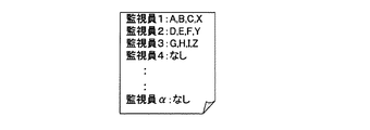
図9は、本実施の形態に係る画像配信システムの動作の具体例を示す図である。この図において、下方向への軸は、時刻を示す。また、時刻毎に、横方向に並んだ複数の監視装置103a,103b,103αは、対応する監視員の監視状態と配信された画像を示す。 FIG. 9 is a diagram showing a specific example of the operation of the image distribution system according to the present embodiment. In this figure, the downward axis indicates time. Further, for each time, the plurality of monitoring devices 103a, 103b, and 103α arranged in the horizontal direction indicate the monitoring status of the corresponding monitoring staff and the distributed images.
まず、時刻t1において、監視装置103a,103b,103αの監視員の監視状態は「可」、監視装置103aに画像A,B,Cが配信され、監視装置103bに画像D,E,Fが配信され、監視装置103αに画像X,Y,Zが配信される。次に、時刻t2において、監視装置103αの監視員が監視を停止した(監視状態入力部32のボタンを押した)場合、監視装置103αの監視員の監視状態は「不可」となり、監視装置103aに画像A,B,C,Xが配信され、監視装置103bに画像D,E,F,Yが配信される。このように、監視状態が「可」から「不可」へ変化した監視装置へ配信されていた画像は、他の監視装置に割り振られることにより監視され続けることができる。次に、時刻t3において、監視装置103αの監視員が監視を再開した(再び監視状態入力部32のボタンを押した)場合、監視装置103αの監視員の監視状態は「可」となり、時刻t1と同様、監視装置103aに画像A,B,Cが配信され、監視装置103bに画像D,E,Fが配信され、監視装置103αに画像X,Y,Zが配信される。このように、監視状態が「不可」から「可」へ変化した監視装置は、再び画像が配信されることにより、監視を再開することができる。 First, at time t1, the monitoring state of the monitoring devices 103a, 103b, and 103α is “OK”, images A, B, and C are distributed to the monitoring device 103a, and images D, E, and F are distributed to the monitoring device 103b. Then, the images X, Y, and Z are distributed to the monitoring device 103α. Next, when the monitoring person of the monitoring device 103α stops monitoring (presses the button of the monitoring state input unit 32) at time t2, the monitoring state of the monitoring person of the monitoring device 103α becomes “impossible”, and the monitoring device 103a. Images A, B, C, and X are distributed to the monitoring device 103b, and images D, E, F, and Y are distributed to the monitoring device 103b. As described above, an image distributed to a monitoring device whose monitoring state has changed from “permitted” to “impossible” can be continuously monitored by being allocated to another monitoring device. Next, when the monitoring person of the monitoring device 103α resumes monitoring at the time t3 (the button of the monitoring state input unit 32 is pressed again), the monitoring state of the monitoring person of the monitoring device 103α becomes “OK”, and the time t1 Similarly, the images A, B, and C are distributed to the monitoring device 103a, the images D, E, and F are distributed to the monitoring device 103b, and the images X, Y, and Z are distributed to the monitoring device 103α. In this way, the monitoring device whose monitoring state has changed from “impossible” to “permitted” can resume monitoring by distributing the image again.
本実施の形態によれば、監視員の監視状態に応じて画像を振り分け、配信することにより、1つの表示部に対して交代用の監視員を用意する必要が無く、地理的に分散して監視員を配置することができる。また、監視対象となる画像の全数に適した監視員の数を決定することが可能になり、余分な監視員を配置する必要が無くなる。 According to the present embodiment, by distributing and distributing images according to the monitoring state of the monitor, there is no need to prepare a replacement monitor for one display unit, and the geographically distributed Watchers can be assigned. In addition, it is possible to determine the number of monitoring personnel suitable for the total number of images to be monitored, and there is no need to arrange extra monitoring personnel.
実施の形態2.
本実施の形態においては、監視装置において監視員の状態を判別する画像配信システムについて説明する。
Embodiment 2. FIG.
In the present embodiment, an image distribution system that determines the state of a monitor in a monitoring device will be described.
まず、本実施の形態に係る画像配信システムの構成について説明する。 First, the configuration of the image distribution system according to the present embodiment will be described.
図10は、本実施の形態に係る画像配信システムの構成の一例を示すブロック図である。この図において、図1と同一符号は図1に示された対象と同一又は相当物を示しており、ここでの説明を省略する。この図は、図1と比較すると、監視装置103の代わりに監視装置113を備える。また、監視装置103と比較すると、監視装置113は、監視状態入力部32の代わりに監視状態判別部34及びカメラ35を備える。
FIG. 10 is a block diagram showing an example of the configuration of the image distribution system according to the present embodiment. In this figure, the same reference numerals as those in FIG. 1 denote the same or corresponding parts as those in FIG. 1, and the description thereof is omitted here. Compared with FIG. 1, this figure includes a monitoring device 113 instead of the monitoring device 103. In comparison with the monitoring device 103, the monitoring device 113 includes a monitoring
次に、本実施の形態に係る画像配信システムの動作について説明する。 Next, the operation of the image distribution system according to the present embodiment will be described.
カメラ35は、監視時に監視員の顔を正面から撮影するように設置され、撮影した画像を監視状態画像として監視状態判別部34へ出力する。監視状態判別部34は、監視状態画像に基づいて、監視員の監視状態を判別する監視状態判別処理を行う。なお、カメラ35の代わりに他のセンサを用いて監視員の監視状態を検出しても良い。
The
次に、監視状態判別処理について説明する。 Next, the monitoring state determination process will be described.
最初に、監視員が瞼を閉じている時間を示す閉じ時間が初期化されている。図11は、本実施の形態に係る監視状態判別処理の動作の一例を示すフローチャートである。まず、監視状態判別部34は、カメラ35から監視状態画像を取得する(S71)。次に、監視状態判別部34は、監視状態画像中に顔があるか否かの判定を行い(S72)、顔が無い場合(S73、無し)、監視不可能と判定して(S87)このフローは終了し、顔がある場合(S73、有り)、次の処理へ移行する。
Initially, a closing time is initialized that indicates how long the observer is closing the bag. FIG. 11 is a flowchart showing an example of the operation of the monitoring state determination process according to the present embodiment. First, the monitoring
次に、監視状態判別部34は、監視状態画像中の顔の向きの判定を行い(S74)、顔の向きが正面向き付近の所定の範囲外である場合、即ちよそ見をしているような場合(S75,範囲外)、監視不可能と判定して(S87)このフローは終了し、顔の向きが正面向き付近の所定の範囲内である場合(S75,範囲内)、次の処理へ移行する。次に、監視状態判別部34は、監視状態画像中の目の開閉の判定を行い(S76)、目が開いているか否かの判断を行う(S77)。
Next, the monitoring
目が開いている場合(S77,Yes)、監視状態判別部34は、監視可能と判定し(S81)、閉じ時間を初期化し(S82)、このフローは終了する。
When the eyes are open (S77, Yes), the monitoring
目が閉じている場合(S77,No)、監視状態判別部34は、閉じ時間を初期化してから現在までの時間を新たな閉じ時間として更新し(S84)、閉じ時間が所定の閾値以下であるか否かの判断を行い、閾値以下である場合(S85,閾値以下)、監視可能と判定して(S86)このフローは終了し、閾値より長い場合(S85,閾値より長い)、監視不可能と判定して(S87)このフローは終了する。ここで、閾値は、瞬きとみなすことができる閉じ時間の上限を示す。
When the eyes are closed (S77, No), the monitoring
次に、監視状態判別部34は、監視状態判定処理による判定結果(監視可能または監視不可能)を状態情報として監視員情報管理部12へ送信する。監視員状態管理部12は、受信した状態情報に従って、監視状態リストを更新する。
Next, the monitoring
また、本実施の形態における画像配信システムにおけるその他の動作は、実施の形態1と同様である。 Other operations in the image distribution system in the present embodiment are the same as those in the first embodiment.
本実施の形態によれば、監視員がボタンなどを操作することなく、監視員の離席などによる監視不可能な状態を判別することができる。更に、監視員の意識低下などによる監視不可能な状態を判別することができることにより、監視漏れを低減することができる。従って、監視漏れによる異常発見の遅れを低減することができる。 According to the present embodiment, it is possible to determine an unmonitorable state due to the absence of the monitor by the monitor without operating a button or the like. Furthermore, since it is possible to determine a state that cannot be monitored due to a decrease in the consciousness of the monitor, it is possible to reduce monitoring omissions. Therefore, it is possible to reduce a delay in finding an abnormality due to monitoring omission.
実施の形態3.
本実施の形態においては、センターシステムにおいて監視員の状態を判別する画像配信システムについて説明する。
Embodiment 3 FIG.
In the present embodiment, an image distribution system that determines the state of a supervisor in the center system will be described.
まず、本実施の形態に係る画像配信システムの構成について説明する。 First, the configuration of the image distribution system according to the present embodiment will be described.
図12は、本実施の形態に係る画像配信システムの構成の一例を示すブロック図である。この図において、図10と同一符号は図10に示された対象と同一又は相当物を示しており、ここでの説明を省略する。この図は、図10と比較すると、センターシステム101の代わりにセンターシステム121を備え、監視装置113の代わりに監視装置123を備える。また、センターシステム101と比較すると、センターシステム121は、新たに監視状態判別部14を備える。また、監視装置113と比較すると、監視装置123は、監視状態判別部34を必要としない。
FIG. 12 is a block diagram showing an example of the configuration of the image distribution system according to the present embodiment. In this figure, the same reference numerals as those in FIG. 10 denote the same or corresponding parts as those in FIG. 10, and the description thereof is omitted here. Compared with FIG. 10, this figure includes a center system 121 instead of the center system 101, and includes a monitoring device 123 instead of the monitoring device 113. Compared with the center system 101, the center system 121 further includes a monitoring state determination unit 14. Further, as compared with the monitoring device 113, the monitoring device 123 does not require the monitoring
次に、本実施の形態に係る画像配信システムの動作について説明する。 Next, the operation of the image distribution system according to the present embodiment will be described.
カメラ35は、実施の形態2と同様であるが、撮影した監視状態画像を監視状態判別部14へ出力する。監視状態判別部14は、監視状態画像に基づいて、監視員の監視状態を判別する監視状態判別処理を行う。この監視状態判別処理は、実施の形態2と同様である。
The
本実施の形態によれば、センターシステム121において、監視状態判別処理を行うことにより、監視装置123を低コストで実現することができる。 According to the present embodiment, the monitoring system 123 can be realized at low cost by performing the monitoring state determination process in the center system 121.
なお、画像取得部及び配信部は、実施の形態における画像振り分け部11に対応する。また、状態取得部及び標準情報取得部は、実施の形態における監視員情報管理部12に対応する。また、モニタ及び表示制御部は、実施の形態における表示部31に対応する。また、状態検出部は、実施の形態における監視状態入力部32またはカメラ35に対応する。また、状態判別部は、実施の形態における監視状態判別部14または監視状態判別部34に対応する。また、撮像部は、実施の形態におけるカメラ102に対応する。
The image acquisition unit and the distribution unit correspond to the image distribution unit 11 in the embodiment. The status acquisition unit and the standard information acquisition unit correspond to the monitor
また、画像取得ステップは、実施の形態における処理S11に対応する。また、状態取得ステップは、実施の形態における処理S24,S44に対応する。また、配信ステップは、実施の形態における処理S31〜S37,S51〜S57に対応する。 An image acquisition step corresponds to step S11 in the embodiment. The state acquisition step corresponds to the processes S24 and S44 in the embodiment. The distribution step corresponds to the processes S31 to S37 and S51 to S57 in the embodiment.
また、本実施の形態に係るセンターシステムは、情報処理装置に容易に適用することができ、情報処理装置の性能をより高めることができる。ここで、情報処理装置には、例えばサーバ等が含まれ得る。また、本実施の形態に係る監視装置は、情報処理装置に容易に適用することができ、情報処理装置の性能をより高めることができる。ここで、情報処理装置には、例えばPC(Personal Computer)、ワークステーション、携帯情報端末等が含まれ得る。 Further, the center system according to the present embodiment can be easily applied to the information processing apparatus, and can further improve the performance of the information processing apparatus. Here, the information processing apparatus may include, for example, a server. In addition, the monitoring apparatus according to the present embodiment can be easily applied to the information processing apparatus, and can further improve the performance of the information processing apparatus. Here, the information processing apparatus may include, for example, a PC (Personal Computer), a workstation, a portable information terminal, and the like.
更に、センターシステムを構成するコンピュータにおいて上述した各ステップを実行させるプログラムを、画像配信プログラムとして提供することができる。上述したプログラムは、コンピュータにより読取り可能な記録媒体に記憶させることによって、センターシステムを構成するコンピュータに実行させることが可能となる。ここで、上記コンピュータにより読取り可能な記録媒体としては、ROMやRAM等のコンピュータに内部実装される内部記憶装置、CD−ROMやフレキシブルディスク、DVDディスク、光磁気ディスク、ICカード等の可搬型記憶媒体や、コンピュータプログラムを保持するデータベース、或いは、他のコンピュータ並びにそのデータベースや、更に回線上の伝送媒体をも含むものである。 Furthermore, it is possible to provide a program that causes the computer constituting the center system to execute the above-described steps as an image distribution program. The above-described program can be executed by a computer constituting the center system by storing the program in a computer-readable recording medium. Here, examples of the recording medium readable by the computer include an internal storage device such as a ROM and a RAM, a portable storage such as a CD-ROM, a flexible disk, a DVD disk, a magneto-optical disk, and an IC card. It includes a medium, a database holding a computer program, another computer and its database, and a transmission medium on a line.
(付記1) 少なくとも1つのモニタへ画像の配信を行う画像配信システムであって、
前記モニタに表示するための少なくとも1つの画像を取得する画像取得部と、
前記モニタ毎の監視状態を取得する状態取得部と、
前記状態取得部により取得された監視状態に基づいて前記モニタの中から配信先とするモニタを選択し、前記画像取得部により取得された画像から前記配信先とするモニタ毎に配信する画像である配信画像を選択し、該配信画像を対応する前記配信先へ配信する配信部と
を備える画像配信システム。
(付記2) 付記1に記載の画像配信システムにおいて、
前記配信部は、前記監視状態が正常であるモニタを正常モニタとし、該正常モニタを前記配信先のモニタとすることを特徴とする画像配信システム。
(付記3) 付記2に記載の画像配信システムにおいて、
前記配信部は、前記画像取得部により取得された画像を前記配信先とするモニタへ分配し、該分配結果を前記配信先とするモニタ毎の配信画像として更新することを特徴とする画像配信システム。
(付記4) 付記2または付記3に記載の画像配信システムにおいて、
前記画像取得部は更に、取得した画像の撮影元を示す撮影元識別子を取得し、
更に、前記モニタが表示すべき画像である標準画像について、予め設定された前記モニタ毎の前記標準画像の撮影元識別子を取得する標準情報取得部を備え、
前記配信部は、前記正常モニタ以外のモニタを異常モニタとし、前記画像取得部により取得された撮影元識別子と前記標準情報取得部により取得された撮影元識別子とに基づいて、前記正常モニタに対応する標準画像を前記正常モニタへの配信画像とすると共に、前記異常モニタに対応する標準画像を前記正常モニタへ配信することを特徴とする画像配信システム。
(付記5) 付記1乃至付記4のいずれかに記載の画像配信システムにおいて、
前記配信部は、特定の配信先のモニタに対して複数の配信画像が選択された場合、該複数の配信画像を合成して配信画像とし、該配信画像を前記特定の配信先のモニタへ配信することを特徴とする画像配信システム。
(付記6) 付記1乃至付記5のいずれかに記載の画像配信システムにおいて、
前記配信部は、特定の配信先のモニタに対して複数の配信画像が選択された場合、該複数の配信画像と該画像に関する情報である配信情報とを前記特定の配信先へ配信し、
更に、前記配信部により配信された複数の配信画像と配信情報を受信し、前記配信情報に基づいて前記複数の配信画像を合成して1つの表示画像とし、前記特定の配信先におけるモニタに前記表示画像を表示させる表示制御部を備えることを特徴とする画像配信システム。
(付記7) 付記6に記載の画像配信システムにおいて、
前記配信情報は、前記特定の配信先に配信される複数の配信画像の数を含むことを特徴とする画像配信システム。
(付記8) 付記6または付記7に記載の画像配信システムにおいて、
前記配信情報は、前記特定の配信先に配信される複数の配信画像について、該配信画像の表示時の配置の情報を含むことを特徴とする画像配信システム。
(付記9) 付記1乃至付記8のいずれかに記載の画像配信システムにおいて、
更に、前記モニタ毎に設けられ、該モニタの監視状態を検出し、前記状態取得部へ出力する状態検出部を備えることを特徴とする画像配信システム。
(付記10) 付記9に記載の画像配信システムにおいて、
前記状態検出部は、前記モニタの監視者からの入力を前記監視状態として前記状態取得部へ出力することを特徴とする画像配信システム。
(付記11) 付記9に記載の画像配信システムにおいて、
前記状態検出部は、前記モニタの環境の検出を行い、該検出結果を出力し、
更に、前記状態検出部による検出結果に基づいて監視者が前記モニタを正常に監視しているか否かを判別し、前記監視状態として前記状態取得部へ出力する状態判別部を備えることを特徴とする画像配信システム。
(付記12) 付記11に記載の画像配信システムにおいて、
前記状態検出部は、撮影を行うものであり、前記モニタを監視している時の監視者を撮影できるように設置され、撮影結果を検出結果として前記状態判別部へ出力することを特徴とする画像配信システム。
(付記13) 付記12に記載の画像配信システムにおいて、
前記状態判別部は、前記状態検出部による撮影結果から、前記監視者の有無、前記監視者の顔の向き、前記監視者の目が閉じている時間、の少なくともいずれかの抽出を行い、該抽出結果が所定の条件を満たす場合、前記監視状態を正常とすることを特徴とする画像配信システム。
(付記14) 付記1乃至付記13のいずれかに記載の画像配信システムにおいて、
更に、監視対象の撮影を行い、該撮影により得られた画像を前記画像取得部へ出力する撮像部を備えることを特徴とする画像配信システム。
(付記15) 付記1乃至付記14のいずれかに記載の画像配信システムにおいて、
更に、前記モニタ毎に設けられ、前記モニタの監視者による通報の入力を受け付ける通報入力部を備えることを特徴とする画像配信システム。
(付記16) 付記1乃至付記15のいずれかに記載の画像配信システムにおいて、
前記配信部は、前記監視状態が変化する度に、前記配信先及び前記配信画像の選択を行うことを特徴とする画像配信システム。
(付記17) モニタに表示する画像の配信をコンピュータに実行させる画像配信プログラムであって、
前記モニタに表示するための少なくとも1つの画像を取得する画像取得ステップと、
前記モニタ毎の監視状態を取得する状態取得ステップと、
前記状態取得ステップにより取得された監視状態に基づいて前記モニタの中から配信先とするモニタを選択し、前記画像取得ステップにより取得された画像から前記配信先とするモニタ毎に配信する画像である配信画像を選択し、該配信画像を対応する前記配信先へ配信する配信ステップと
をコンピュータに実行させる画像配信プログラム。
(付記18) 付記17に記載の画像配信プログラムにおいて、
前記配信ステップは、前記監視状態が正常であるモニタを正常モニタとし、該正常モニタを前記配信先のモニタとすることを特徴とする画像配信プログラム。
(付記19) 付記18に記載の画像配信プログラムにおいて、
前記配信ステップは、前記画像取得ステップにより取得された画像を前記配信先とするモニタへ分配し、該分配結果を前記配信元毎の配信画像とすることを特徴とする画像配信プログラム。
(付記20) モニタに表示する画像の配信を行う画像配信方法であって、
前記モニタに表示するための少なくとも1つの画像を取得する画像取得ステップと、
前記モニタ毎の監視状態を取得する状態取得ステップと、
前記状態取得ステップにより取得された監視状態に基づいて前記モニタの中から配信先とするモニタを選択し、前記画像取得ステップにより取得された画像から前記配信先とするモニタ毎に配信する画像である配信画像を選択し、該配信画像を対応する前記配信先へ配信する配信ステップと
を実行する画像配信方法。
(Appendix 1) An image delivery system for delivering an image to at least one monitor,
An image acquisition unit for acquiring at least one image to be displayed on the monitor;
A state acquisition unit for acquiring a monitoring state for each monitor;
It is an image that selects a monitor as a delivery destination from among the monitors based on the monitoring state acquired by the status acquisition unit, and that is distributed for each monitor as the delivery destination from the image acquired by the image acquisition unit. An image distribution system comprising: a distribution unit that selects a distribution image and distributes the distribution image to the corresponding distribution destination.
(Appendix 2) In the image delivery system described in Appendix 1,
The image distribution system, wherein the distribution unit sets a monitor in which the monitoring state is normal as a normal monitor, and sets the normal monitor as a monitor of the distribution destination.
(Appendix 3) In the image distribution system described in Appendix 2,
The distribution unit distributes the image acquired by the image acquisition unit to the monitor as the distribution destination, and updates the distribution result as a distribution image for each monitor as the distribution destination. .
(Supplementary Note 4) In the image distribution system according to Supplementary Note 2 or Supplementary Note 3,
The image acquisition unit further acquires a photographing source identifier indicating a photographing source of the acquired image,
In addition, for a standard image that is an image to be displayed by the monitor, a standard information acquisition unit that acquires a photographing source identifier of the standard image for each monitor set in advance is provided,
The distribution unit uses a monitor other than the normal monitor as an abnormal monitor, and corresponds to the normal monitor based on the imaging source identifier acquired by the image acquisition unit and the imaging source identifier acquired by the standard information acquisition unit. A standard image to be distributed to the normal monitor and a standard image corresponding to the abnormal monitor are distributed to the normal monitor.
(Supplementary Note 5) In the image distribution system according to any one of Supplementary Notes 1 to 4,
When a plurality of distribution images are selected for a monitor of a specific distribution destination, the distribution unit combines the plurality of distribution images into a distribution image, and distributes the distribution image to the monitor of the specific distribution destination An image distribution system characterized by:
(Appendix 6) In the image distribution system according to any one of Appendix 1 to Appendix 5,
When a plurality of distribution images are selected for a monitor of a specific distribution destination, the distribution unit distributes the plurality of distribution images and distribution information that is information about the image to the specific distribution destination,
Furthermore, a plurality of distribution images and distribution information distributed by the distribution unit are received, and the plurality of distribution images are combined based on the distribution information into one display image, and the monitor at the specific distribution destination An image distribution system comprising a display control unit for displaying a display image.
(Supplementary note 7) In the image distribution system according to supplementary note 6,
The image distribution system, wherein the distribution information includes the number of a plurality of distribution images distributed to the specific distribution destination.
(Appendix 8) In the image distribution system according to Appendix 6 or Appendix 7,
The image distribution system, wherein the distribution information includes information on an arrangement at the time of displaying the distribution image for a plurality of distribution images distributed to the specific distribution destination.
(Supplementary note 9) In the image distribution system according to any one of supplementary notes 1 to 8,
Furthermore, the image delivery system provided with the state detection part provided for every said monitor, and detecting the monitoring state of this monitor and outputting to the said state acquisition part.
(Supplementary Note 10) In the image delivery system according to Supplementary Note 9,
The state detection unit outputs an input from a monitor of the monitor as the monitoring state to the state acquisition unit.
(Supplementary Note 11) In the image delivery system according to Supplementary Note 9,
The state detection unit detects the environment of the monitor, outputs the detection result,
And a state determination unit that determines whether or not a monitor normally monitors the monitor based on a detection result by the state detection unit, and outputs the state as a monitoring state to the state acquisition unit. Image distribution system.
(Supplementary note 12) In the image distribution system according to supplementary note 11,
The state detection unit is for taking a picture, is installed so as to be able to take a picture of a monitor who is monitoring the monitor, and outputs the result of the photographing to the state determination unit as a detection result. Image distribution system.
(Supplementary note 13) In the image distribution system according to
The state determination unit extracts at least one of the presence / absence of the supervisor, the orientation of the face of the supervisor, and the time during which the eyes of the supervisor are closed from the imaging result of the state detection unit, An image delivery system characterized in that when the extraction result satisfies a predetermined condition, the monitoring state is set to normal.
(Supplementary note 14) In the image distribution system according to any one of supplementary notes 1 to 13,
Furthermore, the image delivery system characterized by including the imaging part which image | photographs the monitoring object and outputs the image obtained by this imaging | photography to the said image acquisition part.
(Supplementary Note 15) In the image delivery system according to any one of Supplementary Notes 1 to 14,
Furthermore, the image delivery system provided with the notification input part provided for every said monitor and receiving the input of the report by the monitor of the said monitor.
(Supplementary Note 16) In the image distribution system according to any one of Supplementary Notes 1 to 15,
The image distribution system, wherein the distribution unit selects the distribution destination and the distribution image every time the monitoring state changes.
(Supplementary Note 17) An image distribution program for causing a computer to distribute an image to be displayed on a monitor,
An image acquisition step of acquiring at least one image to be displayed on the monitor;
A state acquisition step of acquiring a monitoring state for each monitor;
It is an image to be distributed to each monitor to be the distribution destination from the image acquired by the image acquisition step by selecting a monitor to be a distribution destination from the monitors based on the monitoring state acquired by the state acquisition step. An image distribution program for causing a computer to execute a distribution step of selecting a distribution image and distributing the distribution image to the corresponding distribution destination.
(Supplementary note 18) In the image distribution program according to supplementary note 17,
In the distribution step, an image distribution program is characterized in that a monitor in which the monitoring state is normal is a normal monitor, and the normal monitor is the monitor of the distribution destination.
(Supplementary note 19) In the image distribution program according to supplementary note 18,
The distribution step distributes the image acquired in the image acquisition step to the monitor as the distribution destination, and sets the distribution result as a distribution image for each distribution source.
(Supplementary note 20) An image delivery method for delivering an image to be displayed on a monitor,
An image acquisition step of acquiring at least one image to be displayed on the monitor;
A state acquisition step of acquiring a monitoring state for each monitor;
It is an image to be distributed to each monitor to be the distribution destination from the image acquired by the image acquisition step by selecting a monitor to be a distribution destination from the monitors based on the monitoring state acquired by the state acquisition step. A delivery step of selecting a delivery image and delivering the delivery image to the corresponding delivery destination.
11 画像振り分け部、12 監視員情報管理部、13 通報部、14,34 監視状態判別部、31 表示部、32 監視状態入力部、33 通報入力部、101 センターシステム、35,102 カメラ、103 監視装置、104,105 ネットワーク。 DESCRIPTION OF SYMBOLS 11 Image distribution part, 12 Monitoring person information management part, 13 Notification part, 14, 34 Monitoring state discrimination | determination part, 31 Display part, 32 Monitoring state input part, 33 Notification input part, 101 Center system, 35,102 Camera, 103 Monitoring Device, 104, 105 network.
Claims (5)
前記モニタに表示するための少なくとも1つの画像を取得する画像取得部と、
前記モニタ毎の監視状態を取得する状態取得部と、
前記状態取得部により取得された監視状態に基づいて前記モニタの中から配信先とするモニタを選択し、前記画像取得部により取得された画像から前記配信先とするモニタ毎に配信する画像である配信画像を選択し、該配信画像を対応する前記配信先へ配信する配信部と
を備える画像配信システム。 An image delivery system for delivering an image to at least one monitor,
An image acquisition unit for acquiring at least one image to be displayed on the monitor;
A state acquisition unit for acquiring a monitoring state for each monitor;
It is an image that selects a monitor as a delivery destination from among the monitors based on the monitoring state acquired by the status acquisition unit, and that is distributed for each monitor as the delivery destination from the image acquired by the image acquisition unit. An image distribution system comprising: a distribution unit that selects a distribution image and distributes the distribution image to the corresponding distribution destination.
前記配信部は、前記監視状態が正常であるモニタを正常モニタとし、該正常モニタを前記配信先のモニタとすることを特徴とする画像配信システム。 The image delivery system according to claim 1,
The image distribution system, wherein the distribution unit sets a monitor in which the monitoring state is normal as a normal monitor, and sets the normal monitor as a monitor of the distribution destination.
前記配信部は、前記画像取得部により取得された画像を前記配信先とするモニタへ分配し、該分配結果を前記配信先とするモニタ毎の配信画像として更新することを特徴とする画像配信システム。 The image delivery system according to claim 2,
The distribution unit distributes the image acquired by the image acquisition unit to the monitor as the distribution destination, and updates the distribution result as a distribution image for each monitor as the distribution destination. .
前記モニタに表示するための少なくとも1つの画像を取得する画像取得ステップと、
前記モニタ毎の監視状態を取得する状態取得ステップと、
前記状態取得ステップにより取得された監視状態に基づいて前記モニタの中から配信先とするモニタを選択し、前記画像取得ステップにより取得された画像から前記配信先とするモニタ毎に配信する画像である配信画像を選択し、該配信画像を対応する前記配信先へ配信する配信ステップと
をコンピュータに実行させる画像配信プログラム。 An image distribution program for causing a computer to distribute an image to be displayed on a monitor,
An image acquisition step of acquiring at least one image to be displayed on the monitor;
A state acquisition step of acquiring a monitoring state for each monitor;
It is an image to be distributed to each monitor to be the distribution destination from the image acquired by the image acquisition step by selecting a monitor to be a distribution destination from the monitors based on the monitoring state acquired by the state acquisition step. An image distribution program for causing a computer to execute a distribution step of selecting a distribution image and distributing the distribution image to the corresponding distribution destination.
前記モニタに表示するための少なくとも1つの画像を取得する画像取得ステップと、
前記モニタ毎の監視状態を取得する状態取得ステップと、
前記状態取得ステップにより取得された監視状態に基づいて前記モニタの中から配信先とするモニタを選択し、前記画像取得ステップにより取得された画像から前記配信先とするモニタ毎に配信する画像である配信画像を選択し、該配信画像を対応する前記配信先へ配信する配信ステップと
を実行する画像配信方法。 An image distribution method for distributing an image to be displayed on a monitor,
An image acquisition step of acquiring at least one image to be displayed on the monitor;
A state acquisition step of acquiring a monitoring state for each monitor;
It is an image to be distributed to each monitor to be the distribution destination from the image acquired by the image acquisition step by selecting a monitor to be a distribution destination from the monitors based on the monitoring state acquired by the state acquisition step. A delivery step of selecting a delivery image and delivering the delivery image to the corresponding delivery destination.
Priority Applications (2)
| Application Number | Priority Date | Filing Date | Title |
|---|---|---|---|
| JP2006249252A JP2008072447A (en) | 2006-09-14 | 2006-09-14 | Image distribution system, image distribution program, and image distribution method |
| US11/648,535 US20080068464A1 (en) | 2006-09-14 | 2007-01-03 | System for delivering images, program for delivering images, and method for delivering images |
Applications Claiming Priority (1)
| Application Number | Priority Date | Filing Date | Title |
|---|---|---|---|
| JP2006249252A JP2008072447A (en) | 2006-09-14 | 2006-09-14 | Image distribution system, image distribution program, and image distribution method |
Publications (1)
| Publication Number | Publication Date |
|---|---|
| JP2008072447A true JP2008072447A (en) | 2008-03-27 |
Family
ID=39188139
Family Applications (1)
| Application Number | Title | Priority Date | Filing Date |
|---|---|---|---|
| JP2006249252A Withdrawn JP2008072447A (en) | 2006-09-14 | 2006-09-14 | Image distribution system, image distribution program, and image distribution method |
Country Status (2)
| Country | Link |
|---|---|
| US (1) | US20080068464A1 (en) |
| JP (1) | JP2008072447A (en) |
Cited By (2)
| Publication number | Priority date | Publication date | Assignee | Title |
|---|---|---|---|---|
| WO2017061239A1 (en) * | 2015-10-09 | 2017-04-13 | 株式会社日立国際電気 | Surveillance system |
| JP2018206222A (en) * | 2017-06-07 | 2018-12-27 | ヤフー株式会社 | Determination apparatus, determination method, and determination program |
Families Citing this family (8)
| Publication number | Priority date | Publication date | Assignee | Title |
|---|---|---|---|---|
| WO2006034135A2 (en) | 2004-09-17 | 2006-03-30 | Proximex | Adaptive multi-modal integrated biometric identification detection and surveillance system |
| US20080129822A1 (en) * | 2006-11-07 | 2008-06-05 | Glenn Daniel Clapp | Optimized video data transfer |
| US20080122932A1 (en) * | 2006-11-28 | 2008-05-29 | George Aaron Kibbie | Remote video monitoring systems utilizing outbound limited communication protocols |
| US20080143831A1 (en) * | 2006-12-15 | 2008-06-19 | Daniel David Bowen | Systems and methods for user notification in a multi-use environment |
| US9544563B1 (en) | 2007-03-23 | 2017-01-10 | Proximex Corporation | Multi-video navigation system |
| US7777783B1 (en) | 2007-03-23 | 2010-08-17 | Proximex Corporation | Multi-video navigation |
| JP6415061B2 (en) | 2014-02-19 | 2018-10-31 | キヤノン株式会社 | Display control apparatus, control method, and program |
| JP2015220693A (en) * | 2014-05-20 | 2015-12-07 | キヤノン株式会社 | Imaging apparatus, imaging system, control method therefor, and program |
Family Cites Families (22)
| Publication number | Priority date | Publication date | Assignee | Title |
|---|---|---|---|---|
| US4992866A (en) * | 1989-06-29 | 1991-02-12 | Morgan Jack B | Camera selection and positioning system and method |
| EP0776573A4 (en) * | 1994-07-26 | 1998-04-15 | Maxpro Systems Pty Ltd | A video security system |
| JPH0937358A (en) * | 1995-07-20 | 1997-02-07 | Sony Corp | Keyboard and video camera control system |
| JP3996960B2 (en) * | 1996-01-30 | 2007-10-24 | キヤノン株式会社 | Camera control system |
| KR100200616B1 (en) * | 1996-09-02 | 1999-06-15 | 윤종용 | Display device for watching-screen dividing and method therefor |
| JP3869897B2 (en) * | 1997-01-28 | 2007-01-17 | キヤノン株式会社 | Camera control system, video receiving apparatus, control method, and storage medium |
| GB2329539B (en) * | 1997-09-17 | 2002-05-15 | Sony Uk Ltd | Security System |
| US20020097322A1 (en) * | 2000-11-29 | 2002-07-25 | Monroe David A. | Multiple video display configurations and remote control of multiple video signals transmitted to a monitoring station over a network |
| JP4235300B2 (en) * | 1999-01-14 | 2009-03-11 | キヤノン株式会社 | Communications system |
| US7124427B1 (en) * | 1999-04-30 | 2006-10-17 | Touch Technologies, Inc. | Method and apparatus for surveillance using an image server |
| US6330025B1 (en) * | 1999-05-10 | 2001-12-11 | Nice Systems Ltd. | Digital video logging system |
| US7310111B2 (en) * | 1999-08-12 | 2007-12-18 | Innovation Institute | Video monitoring and security system |
| AUPQ684600A0 (en) * | 2000-04-11 | 2000-05-11 | Safehouse International Limited | An object monitoring system |
| US7382397B2 (en) * | 2000-07-26 | 2008-06-03 | Smiths Detection, Inc. | Systems and methods for controlling devices over a network |
| US6496117B2 (en) * | 2001-03-30 | 2002-12-17 | Koninklijke Philips Electronics N.V. | System for monitoring a driver's attention to driving |
| US20020194610A1 (en) * | 2001-06-15 | 2002-12-19 | Kuo-Liang Lin | Surveillance digital video recorder |
| US7194109B2 (en) * | 2001-08-30 | 2007-03-20 | Hitachi Kokusai Electric, Inc. | Method and system for delivering monitored image signal of subject to be monitored |
| US7365772B2 (en) * | 2001-10-11 | 2008-04-29 | Sanyo Electric Co., Ltd. | Communication method and monitoring camera system |
| US20030098910A1 (en) * | 2001-11-29 | 2003-05-29 | Pilsoo Kim | Apparatus and method of providing point-of-sale surveillance and auditing of sale transactions of goods |
| US20040075741A1 (en) * | 2002-10-17 | 2004-04-22 | Berkey Thomas F. | Multiple camera image multiplexer |
| US6985079B1 (en) * | 2002-12-03 | 2006-01-10 | Magnetic Moments, Llc | System and method for enhanced alertness and efficient distributed management for video surveillance |
| JP4716083B2 (en) * | 2004-07-27 | 2011-07-06 | ソニー株式会社 | Information processing apparatus and method, recording medium, and program |
-
2006
- 2006-09-14 JP JP2006249252A patent/JP2008072447A/en not_active Withdrawn
-
2007
- 2007-01-03 US US11/648,535 patent/US20080068464A1/en not_active Abandoned
Cited By (3)
| Publication number | Priority date | Publication date | Assignee | Title |
|---|---|---|---|---|
| WO2017061239A1 (en) * | 2015-10-09 | 2017-04-13 | 株式会社日立国際電気 | Surveillance system |
| JPWO2017061239A1 (en) * | 2015-10-09 | 2018-07-12 | 株式会社日立国際電気 | Monitoring system |
| JP2018206222A (en) * | 2017-06-07 | 2018-12-27 | ヤフー株式会社 | Determination apparatus, determination method, and determination program |
Also Published As
| Publication number | Publication date |
|---|---|
| US20080068464A1 (en) | 2008-03-20 |
Similar Documents
| Publication | Publication Date | Title |
|---|---|---|
| US12088966B2 (en) | Electronic patient sitter management system and method for implementing | |
| JP5995243B2 (en) | Watch system | |
| US20190230402A1 (en) | Premises Monitoring System | |
| EP2674924B1 (en) | A telemetry monitoring system and a data recovery method for a telemetry monitoring system | |
| US9934663B2 (en) | Apparatus and method for improved live monitoring and alarm handling in video surveillance systems | |
| JP2011060058A (en) | Imaging apparatus and monitoring system | |
| JP2008072447A (en) | Image distribution system, image distribution program, and image distribution method | |
| JP2013089076A (en) | Support system of fire alarm facility | |
| JPWO2019216045A1 (en) | System and system control method | |
| KR20190039278A (en) | Video load balancing system for P2P server network | |
| JP5824332B2 (en) | Monitoring device | |
| JP2015060530A (en) | Watching system, watching method, watching terminal, management terminal, program and recording medium | |
| JP6585319B1 (en) | System, bot, and method for information sharing | |
| JP2010074527A (en) | Monitor control apparatus, and monitor system | |
| JP6322304B2 (en) | Fire alarm equipment support system | |
| JP2013033417A (en) | Terminal monitoring device, terminal monitoring system and program | |
| CN112804480A (en) | Monitoring and warning system | |
| JP2020052664A (en) | Work management apparatus, control method thereof, and program | |
| US20090231119A1 (en) | Remote data collection in an alarm or security system | |
| KR101609533B1 (en) | The life care system | |
| JP7845557B2 (en) | Display control device and monitoring system | |
| JP2005311820A (en) | Emergency reporting system | |
| JP6921550B2 (en) | Monitoring system and monitoring method | |
| JP7453447B1 (en) | Information processing system, information processing method and program | |
| JP6228254B2 (en) | Fire alarm equipment support system |
Legal Events
| Date | Code | Title | Description |
|---|---|---|---|
| A621 | Written request for application examination |
Free format text: JAPANESE INTERMEDIATE CODE: A621 Effective date: 20090512 |
|
| A761 | Written withdrawal of application |
Free format text: JAPANESE INTERMEDIATE CODE: A761 Effective date: 20100115 |