JP2007334827A - Mobile terminal device - Google Patents
Mobile terminal device Download PDFInfo
- Publication number
- JP2007334827A JP2007334827A JP2006169136A JP2006169136A JP2007334827A JP 2007334827 A JP2007334827 A JP 2007334827A JP 2006169136 A JP2006169136 A JP 2006169136A JP 2006169136 A JP2006169136 A JP 2006169136A JP 2007334827 A JP2007334827 A JP 2007334827A
- Authority
- JP
- Japan
- Prior art keywords
- display panel
- display
- transparent
- touch
- terminal device
- Prior art date
- Legal status (The legal status is an assumption and is not a legal conclusion. Google has not performed a legal analysis and makes no representation as to the accuracy of the status listed.)
- Pending
Links
Images


Classifications
-
- G—PHYSICS
- G06—COMPUTING OR CALCULATING; COUNTING
- G06F—ELECTRIC DIGITAL DATA PROCESSING
- G06F1/00—Details not covered by groups G06F3/00 - G06F13/00 and G06F21/00
- G06F1/16—Constructional details or arrangements
- G06F1/1613—Constructional details or arrangements for portable computers
- G06F1/1626—Constructional details or arrangements for portable computers with a single-body enclosure integrating a flat display, e.g. Personal Digital Assistants [PDAs]
-
- G—PHYSICS
- G06—COMPUTING OR CALCULATING; COUNTING
- G06F—ELECTRIC DIGITAL DATA PROCESSING
- G06F1/00—Details not covered by groups G06F3/00 - G06F13/00 and G06F21/00
- G06F1/16—Constructional details or arrangements
- G06F1/1613—Constructional details or arrangements for portable computers
- G06F1/1633—Constructional details or arrangements of portable computers not specific to the type of enclosures covered by groups G06F1/1615 - G06F1/1626
- G06F1/1684—Constructional details or arrangements related to integrated I/O peripherals not covered by groups G06F1/1635 - G06F1/1675
- G06F1/169—Constructional details or arrangements related to integrated I/O peripherals not covered by groups G06F1/1635 - G06F1/1675 the I/O peripheral being an integrated pointing device, e.g. trackball in the palm rest area, mini-joystick integrated between keyboard keys, touch pads or touch stripes
-
- G—PHYSICS
- G06—COMPUTING OR CALCULATING; COUNTING
- G06F—ELECTRIC DIGITAL DATA PROCESSING
- G06F3/00—Input arrangements for transferring data to be processed into a form capable of being handled by the computer; Output arrangements for transferring data from processing unit to output unit, e.g. interface arrangements
- G06F3/01—Input arrangements or combined input and output arrangements for interaction between user and computer
- G06F3/048—Interaction techniques based on graphical user interfaces [GUI]
- G06F3/0487—Interaction techniques based on graphical user interfaces [GUI] using specific features provided by the input device, e.g. functions controlled by the rotation of a mouse with dual sensing arrangements, or of the nature of the input device, e.g. tap gestures based on pressure sensed by a digitiser
- G06F3/0488—Interaction techniques based on graphical user interfaces [GUI] using specific features provided by the input device, e.g. functions controlled by the rotation of a mouse with dual sensing arrangements, or of the nature of the input device, e.g. tap gestures based on pressure sensed by a digitiser using a touch-screen or digitiser, e.g. input of commands through traced gestures
-
- G—PHYSICS
- G06—COMPUTING OR CALCULATING; COUNTING
- G06F—ELECTRIC DIGITAL DATA PROCESSING
- G06F3/00—Input arrangements for transferring data to be processed into a form capable of being handled by the computer; Output arrangements for transferring data from processing unit to output unit, e.g. interface arrangements
- G06F3/01—Input arrangements or combined input and output arrangements for interaction between user and computer
- G06F3/048—Interaction techniques based on graphical user interfaces [GUI]
- G06F3/0487—Interaction techniques based on graphical user interfaces [GUI] using specific features provided by the input device, e.g. functions controlled by the rotation of a mouse with dual sensing arrangements, or of the nature of the input device, e.g. tap gestures based on pressure sensed by a digitiser
- G06F3/0488—Interaction techniques based on graphical user interfaces [GUI] using specific features provided by the input device, e.g. functions controlled by the rotation of a mouse with dual sensing arrangements, or of the nature of the input device, e.g. tap gestures based on pressure sensed by a digitiser using a touch-screen or digitiser, e.g. input of commands through traced gestures
- G06F3/04886—Interaction techniques based on graphical user interfaces [GUI] using specific features provided by the input device, e.g. functions controlled by the rotation of a mouse with dual sensing arrangements, or of the nature of the input device, e.g. tap gestures based on pressure sensed by a digitiser using a touch-screen or digitiser, e.g. input of commands through traced gestures by partitioning the display area of the touch-screen or the surface of the digitising tablet into independently controllable areas, e.g. virtual keyboards or menus
Landscapes
- Engineering & Computer Science (AREA)
- Theoretical Computer Science (AREA)
- General Engineering & Computer Science (AREA)
- Human Computer Interaction (AREA)
- Physics & Mathematics (AREA)
- General Physics & Mathematics (AREA)
- Computer Hardware Design (AREA)
- Position Input By Displaying (AREA)
- User Interface Of Digital Computer (AREA)
- Devices For Indicating Variable Information By Combining Individual Elements (AREA)
- Telephone Set Structure (AREA)
Abstract
【課題】透明な表示パネルを用いて操作性を改善する。
【解決手段】透明な平面表示パネル21と、この平面表示パネルの背面側に貼着された透明なタッチセンサ30と、上記平面表示パネルの両面側を挟持固定する外装体40とで構成される。平面表示パネルは自発光型の表示パネルである。表示パネル21が透明であるため、装置を握持した手の指62を、表示パネル21の表示パネル面60を通して目視できるので、表示パネル面に映し出された画像を遮ることなく、しかもカーソルなどのポインタを使用しないでも、素早く目的のタッチ位置に指62を動かすことができる。
【選択図】 図1
The operability is improved by using a transparent display panel.
SOLUTION: A transparent flat display panel 21, a transparent touch sensor 30 attached to the back side of the flat display panel, and an exterior body 40 that holds and fixes both sides of the flat display panel. . The flat display panel is a self-luminous display panel. Since the display panel 21 is transparent, the finger 62 of the hand holding the device can be seen through the display panel surface 60 of the display panel 21, so that an image projected on the display panel surface is not obstructed and a cursor or the like is displayed. Even without using the pointer, the finger 62 can be quickly moved to the target touch position.
[Selection] Figure 1
Description
この発明は透明な表示パネルを使用した携帯端末装置に関する。詳しくは、透明な表示パネルの背面側に透明なタッチセンサを配することで、透明表示パネルを通して背面側に臨む指のタッチ位置を目視できるようにして、指のタッチ位置を目視によって確認しながら選択操作できるようにしたものである。 The present invention relates to a portable terminal device using a transparent display panel. Specifically, by placing a transparent touch sensor on the back side of the transparent display panel, the touch position of the finger facing the back side can be seen through the transparent display panel, while checking the finger touch position visually A selection operation can be performed.
PDAなどの携帯端末装置にあっては、端末装置が小型で軽量な情報処理装置として開発されているので、できるだけ情報を表示する表示パネル部分の表示面積を大きくしたものが開発されている。 In a portable terminal device such as a PDA, since the terminal device has been developed as a small and lightweight information processing device, a device having a display panel portion for displaying information as large as possible has been developed.
この種携帯端末装置では、片手若しくは両手を使って端末装置本体を支えた状態で、指あるいは表示ペンを用いて表示装置の表示パネル面をタッチしながら入力操作を行う。そうするとどうしても表示パネル面を手で塞ぐ傾向にあるため、表示情報を手が遮ってしまう嫌いがある。 In this type of portable terminal device, an input operation is performed while touching the display panel surface of the display device with a finger or a display pen while supporting the terminal device body with one or both hands. If it does so, there is a tendency to block the display panel surface by hand.
このような問題を解決するものとして、特許文献1あるいは特許文献2などが知られている。特許文献1は、タッチパネルを背面から操作できるようにした携帯端末が開示されている。タッチパネルを携帯端末本体の背面側にくるように設計する場合、端末本体の背面側に配されたタッチパネルの操作位置(タッチ位置)が目視できないため、この操作位置を確認できるように表示パネル面にカーソルなどのポインタを表示する構成となされている。
As a means for solving such a problem,
特許文献2も同じく、タッチスイッチを表示部の背面側に配した携帯機器が開示されており、この場合もタッチスイッチの操作位置を確認できるように表示パネル面にはタッチ位置を示すカーソルなどのポインタが表示されるようになっている。
Similarly,
ところで、特許文献1および特許文献2は共に、表示パネルとしては液晶などの表示素子を使用しているので、表示パネルとしては反射式のものが使用されている。そのため、この表示パネルを通して背面のタッチパネルの位置を目視により確認することができないので、表示パネルには指などのタッチ位置を表示するためのポインタの表示が必要になる。
By the way, since both
これに加えて、タッチパネルにタッチする前の段階では、表示パネルにはカーソルが表示されないため、タッチパネルのどの位置に指が位置しているのかを正確には把握できない。タッチパネルにタッチして始めてカーソルが表示されて表示パネル面に対する指の位置が確認できるからである。そのため、目的の操作位置を探すまでの操作性が悪い。直感的な操作が難しいからである。 In addition to this, since the cursor is not displayed on the display panel before the touch panel is touched, it is impossible to accurately grasp the position of the finger on the touch panel. This is because the cursor is displayed only after touching the touch panel, and the position of the finger with respect to the display panel surface can be confirmed. Therefore, the operability until the target operation position is searched is poor. This is because intuitive operation is difficult.
そこで、この発明はこのような従来の課題を解決したものであって、特に透明な表示パネルと、表示パネルの背面側に透明なタッチスクリーンを配置することで、目視しながら表示パネルの背面側より操作できるようにして操作性を改善した携帯端末装置を提案するものである。 Therefore, the present invention solves such a conventional problem, and particularly by arranging a transparent display panel and a transparent touch screen on the back side of the display panel, the back side of the display panel is visually observed. The present invention proposes a portable terminal device that can be operated more and has improved operability.
上述の課題を解決するため、請求項1に記載したこの発明に係る携帯端末装置は、透明な平面表示装置と、
この平面表示装置の背面側に貼着された透明なタッチセンサと、
上記平面表示装置の両面側を挟持固定する外装体とで構成されたことを特徴とする。
In order to solve the above-mentioned problem, a mobile terminal device according to the present invention described in
A transparent touch sensor attached to the back side of the flat display device;
The flat panel display device includes an exterior body that holds and fixes both sides of the flat display device.
この発明では、透明な表示装置と、この表示装置の背面側に設けられた透明なタッチセンサとで携帯端末装置が構成される。表示装置は、透明な表示パネルと、その表示駆動系とで構成される。 In this invention, a portable terminal device is comprised by the transparent display apparatus and the transparent touch sensor provided in the back side of this display apparatus. The display device includes a transparent display panel and its display drive system.
表示パネルが透明であるため、端末装置を片手若しくは両手で支えるとき、表示パネルの背面側に添わした指を、この表示パネルを介して目視できる。したがって、表示パネルに画像が表示されても、この画像と指の位置関係を画像を通して把握できる。その結果、操作すべき表示パネル上の位置を簡単に、しかも正確に認識できる。表示パネルの正面側から操作位置を探索するのではないため、表示画像が手や指で遮られることはない。透明な表示装置として有機ELなどが使用される。 Since the display panel is transparent, when the terminal device is supported with one hand or both hands, a finger attached to the back side of the display panel can be visually observed through the display panel. Therefore, even if an image is displayed on the display panel, the positional relationship between the image and the finger can be grasped through the image. As a result, the position on the display panel to be operated can be easily and accurately recognized. Since the operation position is not searched from the front side of the display panel, the display image is not blocked by a hand or a finger. An organic EL or the like is used as a transparent display device.
この発明では、透明な表示装置と、この表示装置の背面側に配された透明なタッチセンサとで携帯端末装置を構成したものである。 In the present invention, a portable terminal device is configured by a transparent display device and a transparent touch sensor disposed on the back side of the display device.
これによれば、表示パネルに表示された画像を直視しながら、表示パネルの背面側よりタッチセンサにタッチして、スイッチの選択や、目的の表示情報などの選択を簡単に行うことができる。したがって表示画像を遮ることなく、操作性を改善できる。 According to this, it is possible to easily select a switch or target display information by touching the touch sensor from the back side of the display panel while directly viewing the image displayed on the display panel. Therefore, the operability can be improved without blocking the display image.
続いて、この発明に係る携帯端末装置の好ましい実施例を図面を参照して詳細に説明する。 Next, a preferred embodiment of the portable terminal device according to the present invention will be described in detail with reference to the drawings.
図1はこの発明に係る携帯端末装置10の概要を示す分解斜視図である。この携帯端末装置10は、平板状をなす透明な表示装置20と、この透明な表示装置20の背面側に貼着されたタッチセンサ(タッチスクリーン)30と、表示装置20をその上下両面からサンドイッチ状に挟持固定する外装体40とで構成される。
FIG. 1 is an exploded perspective view showing an outline of a
表示装置20は、それ自体が発光する(自発光する)透明で扁平な表示パネル21と、その表示駆動系である制御回路基板44とで構成される。制御回路基板44は表示パネル21自体に搭載することもできれば、別体構成であってもよい。図1は後者の例を示す。
The
透明な表示パネル21、この例では有機ELなどの表示パネルを使用した場合である。表示装置20のサイズは任意であるが、テレビ画面のように多少横長な画面サイズのものを例示する。
This is a case where a
表示パネル21の背面側には透明なタッチセンサ30が貼着される。このタッチセンサ30も表示パネル21のサイズと同じサイズのタッチスクリーンであって、透明電極が使用される。この表示パネル21とタッチセンサ30とでタッチパネルが構成される。タッチセンサ30に対するタッチ状態(接触状態)の検知は、静電容量方式、薄膜抵抗方式の何れの検知方式でも採用できる。この例では薄膜抵抗方式が採用されている。
A
背面側にタッチセンサ30が貼着された表示パネル21は扁平な外装体40に装着固定される。外装体40は表示パネル21の背面側に配される装置本体部40Aと、その上面側に配されるカバー体40Bとで構成される。
The
装置本体部40Aは図示するように表示パネル21よりも一回り大きな平板であって、平板中央部には表示パネル21よりも若干小さな開口部41が設けられ、表示パネル21を載置固定できるようになっている。装置本体部40Aの外周部を構成する枠の内部は複数の収納凹部42(42a〜42c)が形成される。図1の例では、下部収納凹部42aに、表示パネル21の画像制御系を含む表示駆動系からなる制御回路基板44が収納される。この制御回路基板44にはバッテリーや内部記憶装置(半導体メモリ)が搭載されているものとする。記憶装置には、外部より挿脱可能な外部記憶装置86を含むものとする。
The apparatus body 40A is a flat plate that is slightly larger than the
装置本体部40Aの左側に位置する収納凹部42bには後述する第1の操作スイッチ46が、右側の収納凹部42cには第2の操作スイッチ48がそれぞれ収納固定される。第1の操作スイッチ46は、この例ではスイッチの選択(確定)とその解除操作を行うスイッチとして機能する。そのため、第1の操作スイッチ46は、上下に並置された選択スイッチ46aと、解除スイッチ46bとで構成される。
A
第2の操作スイッチ48は、表示画面を上下にスクロールするスクロールスイッチとして機能する。第2の操作スイッチ48の面にタッチしながら指を上方に移動することで表示画面は上方にスクロールし、指を下方に移動させると表示画面が下方に移動する(図7,8参照)。図1では上下スクロールのみであるが、表示画面を左右にスクロールするための操作スイッチを設けてもよい。このスクロールスイッチを第1の操作スイッチ46で兼用することも可能である。
The second operation switch 48 functions as a scroll switch that scrolls the display screen up and down. The display screen scrolls upward by moving the finger upward while touching the surface of the
収納凹部42にあって、この例では、さらに下部の収納凹部42a側にスピーカ49が収納固定される。操作スイッチ46,48やタッチセンサ30におけるタッチ操作に連動してスピーカ49を駆動することで、これらスイッチ46,48などのタッチ状態やその確定を報知できる。装置本体部40Aの前面には、必要に応じて外部記憶装置(半導体メモリ装置など)86などの装着端子部85や、USB端子88の装着端子部87などを設けることができる。
In the
装置本体部40Aに表示パネル21を載置すると共に、制御回路基板44などの必要な電子部品を収納凹部42内に収納した状態で表示パネル21の上面よりカバー体40Bが載置固定される。そのため、カバー体40Bにも開口部41と同様な大きさの矩形状の開口部52が穿設されると共に、カバー体40Bの右側面側であって第1の操作スイッチ46と対峙する位置には、第1の操作スイッチ46を挟持固定するために、第1の操作スイッチ46の形状(この例では2つの円孔)にマッチした取り付け孔54が穿設される。同じく、カバー体40Bの左側面側であって第2の操作スイッチ48と対峙する位置にも、第2の操作スイッチ48を挟持固定するために、第2の操作スイッチ48の形状(この例では短冊状)にマッチした取り付け孔56が穿設される。
The
このように表示パネル21を装置本体部40Aとカバー体40Bとで挟持固定することで、携帯に便利な、扁平で透明な携帯端末装置10を構成できる。装置本体部40Aの前面であって、制御回路基板44側には外部記憶装置86を装着できる装着端子部85や、インターネットと接続するためのUSB端子87などが設けられている。
Thus, the flat and transparent portable
表示パネル21の上面およびタッチセンサ30の露出面を保護するため、装置本体部40Aの開口部41およびカバー体40Bの開口部52にはそれぞれ透明な保護フィルム(図示はしない)などが取着されている。これによって傷の付きにくい携帯端末装置とすることができる。
In order to protect the upper surface of the
さて、このように構成された携帯端末装置10を実際に使用する場合には、図2に示すように携帯端末装置10の左右両端側を左右の手65で握持した状態で使用する。表示パネル21もタッチセンサ30も共に透明体であるので、両手で携帯端末装置10を握持すると、表示パネル21の背面側を抱え込んだ指62も表示パネル21を通して目視できる。したがって表示パネル面60上の表示画像と左右の指62の相対位置関係を容易に、しかも確実に把握できる。図2のように表示パネル21を通して目視される、表示パネル21の背面側の指62を破線で示す。
Now, when actually using the mobile
表示内容の特定操作(確定操作)は表示パネル21の背面側に臨む指62の操作で行う。通常は中指で操作される場合が多い。指62がタッチされた個所は、明暗を変えて、例えばハイライト表示したり、ブリンクさせたり、カラーの場合には特定の色に切り替え表示することで、タッチ位置を容易に認識できる。そして、図2に示すように右中指62aを例えば円弧状に動かすことによって、中指62aの軌跡に応じてハイライト位置が変化したり、表示色がその軌跡に追尾して表示される。指62でタッチしたタッチ位置の選択や解除操作、さらには表示パネル面に表示された画像のスクロール操作などは、何れも表示パネル21の上面に位置する第1および第2のスイッチ46,48を選択操作することで行なわれる。
The display content specifying operation (confirmation operation) is performed by operating the
したがって、図2のように携帯端末装置10を両手に握持した状態で、第1の操作スイッチ46を操作すれば最初に表示パネル21の表示パネル面60にはメニュー画面64などが表示される。図3にその表示例を示す。メニュー画面64などが表示されても、表示画像によって表示パネル21の背面側の指62が完全に隠れるのではないので、表示パネル面60に画像が表示されていてもメニュー画面64上の特定の項目に対する指62の現在位置を簡単に把握できる。その結果、特許文献1や特許文献2に開示されているようなポインタを表示することなく、目的の表示個所(表示項目)に指62を簡単に、しかも素早く移動でき、特定の項目付近を何度か探索するような探索作業(先行文献例)もなくなり、操作性が改善される。
Accordingly, when the
このような画像表示状態でも背面側の指62を目視できる特徴は、表示画像の種類や、表示位置には依存しないことは容易に理解できる。
It can be easily understood that the characteristic that the
表示パネル面60に例えば図4に示すような数字が表示されたボタン70が表示されているときで、数字「4」のボタン72の表示位置に対応したタッチセンサ30の対応位置に指62(この例では、中指62a)がタッチされると、図5に示すようにそのボタン72の表示状態が変化し、そのボタン72がまさに選択されようとしていることが目視できる。タッチ位置のボタン72の選択は、表示パネル面60側の確定スイッチ46aを操作することで確定する。
For example, when a
図6は、表示パネル面60にソフトウエアキーボード74を表示した場合で、このソフトウエアキーボード74のキーを選択しながら文章などを作成する場合の一例を示すもので、表示パネル面60のうち下半分がソフトウエアキーボード74の表示エリア60Aとなり、上半分が文字等の表示エリア60Bとなる。表示エリア60Bに選択された文字などが表示される。
FIG. 6 shows an example of a case in which a
図7は、表示画像のスクロール例を示す。表示パネル面60に表示できる情報以上の情報が含まれているときは、第2の操作スイッチ48を利用して表示画像を上下にスクロールすることで、表示パネル面60に表示される画像をスクロール表示できる。そして、表示画像にwebブラウザにリンクするアドレス78が表示されているハイパーリンクの場合には、図8のように、表示画像を下方にスクロールして、アドレス78の表示位置を表示パネル21の背面側よりタッチすれば、そのアドレス78にリンクした情報を表示パネル面60に表示できる。
FIG. 7 shows a scroll example of the display image. When information more than information that can be displayed on the
図9は、この発明に係る携帯端末装置10における制御系の一例を示すブロック図である。制御回路基板44には周知のように装置全体の制御を司る制御部(CPU)80を始めとして、各種設定プログラムやワーキングメモリエリアなどが確保されたメモリ手段81、表示パネル面60に特定の画像を表示するためのGUI(Grafic User Interface)82、操作スイッチ46,48などが接続される。
FIG. 9 is a block diagram showing an example of a control system in the mobile
制御部80にはさらにタッチセンサ30のタッチ位置(表示パネル面60の平面座標)を認識する座標認識部83が接続され、座標認識部83で認識された座標情報が制御部80に供給されて、表示パネル21に対して表示画像の切り替え表示や、タッチ位置の表示など、選択された表示項目に対応した処理が実行される。
The
この処理に加えて制御部80ではタッチセンサ30へのタッチが検出されると駆動部89が駆動されてスピーカ49からブザー音などが放音される。制御部80ではさらに接続端子85に接続された外部記憶装置86からの書き込み読み出し処理や、USB端子88から入力した外部情報などが処理される。
In addition to this processing, when the
図10は実施例1における処理例を示す要部のフローチャートである。
このフローチャートは、タッチセンサ30へのタッチからタッチ位置の確定までの処理例であって、タッチセンサ30へのセンサタッチが検知されると、タッチ位置の座標(x,y)が算出されると共に、タッチ位置の該当文字などが例えばハイライトされる(ステップ91,92,93)。
FIG. 10 is a flowchart of a main part showing a processing example in the first embodiment.
This flowchart is an example of processing from the touch on the
次に、第1の操作スイッチ46のうち確定スイッチ46aおよび解除スイッチ46bの各操作状態がチェックされ(ステップ94)、解除スイッチ46aの操作であるときは初期状態に遷移する。ステップ94において確定スイッチ46aの操作であると判断されたときは、確定状態を報知するためのブザー音が放音されて初期状態に遷移する(ステップ95)。
Next, each operation state of the
図11はこの発明に係る携帯端末装置10の他の実施例を示す。
この実施例は、図10に示す操作スイッチ46,48と同等の機能を、タッチセンサによって実現したものである。そのため、図1に示したような第1および第2の操作スイッチ46,48が省かれた構成となされると共に、透明な表示パネル21の背面側に透明な第1のタッチセンサ30が貼着されると共に、この表示パネル21の前面に同じく透明な第2のタッチセンサ100が貼着されて携帯端末装置10が構成される。
FIG. 11 shows another embodiment of the portable
In this embodiment, functions equivalent to those of the operation switches 46 and 48 shown in FIG. 10 are realized by a touch sensor. Therefore, the first and second operation switches 46 and 48 as shown in FIG. 1 are omitted, and the transparent
第2のタッチセンサ100は、第1の操作スイッチ46や第2の操作スイッチ48と同様な機能を持たせる。そのため、図12に示すように第2のタッチセンサ100は、第1の操作スイッチ46と同じ機能を実現するために上下に2分割された帯状のセンサとして機能させる。例えば、下段側のセンサ100Aを選択センサとし、上段のセンサ100Bを解除センサとして使用する。何れもセンサ100Aあるいは100Bの任意のタッチ位置で対応する機能が選択できる。
The
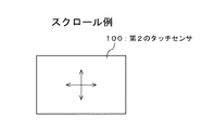
また、図13に示すように第2の操作スイッチ48と同じ機能を実現するために、第2のタッチセンサ100の面上を任意のタッチ位置から上下左右に連続的に移動(矢印参照)させることで、表示パネル面60に表示された画像を上下左右にスクロールさせるスクロールセンサとして機能させる。
Further, as shown in FIG. 13, in order to realize the same function as that of the
第2のタッチセンサ100をこのように選択、解除機能およびスクロール機能を持たせることで、操作スイッチ46,48と同等の動作を実現できる。操作スイッチ46.48が省略できるため、外装体40自体を図1の場合よりもコンパクト化できる。第2のタッチセンサ100を設けても、表示パネル面60の表示画像を遮ることなく操作できることは言うまでもない。
By providing the
上述した実施例1および実施例2では、表示パネル21として白黒(モノカラー)の表示パネルを使用した場合について説明したが、カラー表示の表示パネル21にも適用できる。
In the above-described first and second embodiments, the case where a monochrome (monocolor) display panel is used as the
この発明は、PDAのような情報端末装置、携帯電話などの携帯端末機器に適用できる。 The present invention can be applied to an information terminal device such as a PDA and a mobile terminal device such as a mobile phone.
10・・・携帯端末装置、21・・・表示パネル、30、100・・・タッチセンサ、40・・・外装体、42・・・収納凹部、46,48・・・操作スイッチ、41,52・・・開口部、62・・・指、60・・・表示パネル面、80・・・制御部、86・・・外部記憶装置
DESCRIPTION OF
Claims (2)
この平面表示装置の背面側に貼着された透明なタッチセンサと、
上記平面表示装置の両面側を挟持固定する外装体とで構成された
ことを特徴とする携帯端末装置。 A transparent flat panel display,
A transparent touch sensor attached to the back side of the flat display device;
And an exterior body that sandwiches and fixes both sides of the flat display device.
The portable terminal device characterized by the above-mentioned.
ことを特徴とする請求項1記載の携帯端末装置。 2. The portable terminal device according to claim 1, wherein the flat display device is a self-luminous display device and includes a display panel and a display driving system thereof.
Priority Applications (2)
| Application Number | Priority Date | Filing Date | Title |
|---|---|---|---|
| JP2006169136A JP2007334827A (en) | 2006-06-19 | 2006-06-19 | Mobile terminal device |
| US11/818,862 US20070291015A1 (en) | 2006-06-19 | 2007-06-15 | Portable terminal equipment |
Applications Claiming Priority (1)
| Application Number | Priority Date | Filing Date | Title |
|---|---|---|---|
| JP2006169136A JP2007334827A (en) | 2006-06-19 | 2006-06-19 | Mobile terminal device |
Publications (1)
| Publication Number | Publication Date |
|---|---|
| JP2007334827A true JP2007334827A (en) | 2007-12-27 |
Family
ID=38861068
Family Applications (1)
| Application Number | Title | Priority Date | Filing Date |
|---|---|---|---|
| JP2006169136A Pending JP2007334827A (en) | 2006-06-19 | 2006-06-19 | Mobile terminal device |
Country Status (2)
| Country | Link |
|---|---|
| US (1) | US20070291015A1 (en) |
| JP (1) | JP2007334827A (en) |
Cited By (14)
| Publication number | Priority date | Publication date | Assignee | Title |
|---|---|---|---|---|
| JP2010122383A (en) * | 2008-11-18 | 2010-06-03 | Sharp Corp | Display apparatus |
| JP2010160775A (en) * | 2009-01-08 | 2010-07-22 | Prime View Internatl Co Ltd | Touch-control structure for flexible display device |
| JP2011130441A (en) * | 2009-12-15 | 2011-06-30 | Lg Electronics Inc | Mobile terminal |
| JP2012152357A (en) * | 2011-01-25 | 2012-08-16 | Sony Computer Entertainment Inc | Portable electronic device |
| EP2500813A2 (en) | 2011-03-17 | 2012-09-19 | Sony Corporation | Information processing apparatus, information processing method, and computer-readable storage medium |
| JP2012230519A (en) * | 2011-04-26 | 2012-11-22 | Kyocera Corp | Portable terminal, touch panel operation program and touch panel operation method |
| JP2012247921A (en) * | 2011-05-26 | 2012-12-13 | Konami Digital Entertainment Co Ltd | Information display device, information display method, and program |
| JP2013045255A (en) * | 2011-08-23 | 2013-03-04 | Kyocera Corp | Display device |
| KR101284496B1 (en) * | 2010-01-06 | 2013-07-16 | 애플 인크. | Transparent electronic device |
| JP2014106978A (en) * | 2012-11-26 | 2014-06-09 | Samsung Electronics Co Ltd | Touch input method and portable terminal |
| US9519371B2 (en) | 2012-07-04 | 2016-12-13 | Canon Kabushiki Kaisha | Display device and control method therefor |
| US9671881B2 (en) | 2011-11-29 | 2017-06-06 | Nec Corporation | Electronic device, operation control method and recording medium |
| JPWO2020031018A1 (en) * | 2018-08-09 | 2020-02-13 | ||
| US11755270B2 (en) | 2019-10-24 | 2023-09-12 | Japan Display Inc. | Display device with a detection electrode |
Families Citing this family (17)
| Publication number | Priority date | Publication date | Assignee | Title |
|---|---|---|---|---|
| JP5586826B2 (en) | 2007-09-28 | 2014-09-10 | 京セラ株式会社 | Portable electronic devices |
| JP4364273B2 (en) * | 2007-12-28 | 2009-11-11 | パナソニック株式会社 | Portable terminal device, display control method, and display control program |
| KR101592296B1 (en) * | 2008-09-03 | 2016-02-05 | 엘지전자 주식회사 | Mobile terminal and its object selection and execution method |
| KR101563523B1 (en) * | 2009-01-30 | 2015-10-28 | 삼성전자주식회사 | Mobile terminal having dual touch screen and method for displaying user interface thereof |
| US8731618B2 (en) * | 2009-04-23 | 2014-05-20 | Apple Inc. | Portable electronic device |
| KR101648747B1 (en) * | 2009-10-07 | 2016-08-17 | 삼성전자 주식회사 | Method for providing user interface using a plurality of touch sensor and mobile terminal using the same |
| TW201122992A (en) * | 2009-12-31 | 2011-07-01 | Askey Computer Corp | Cursor touch-control handheld electronic device |
| AU2015200494B2 (en) * | 2010-01-06 | 2016-04-14 | Apple Inc. | Transparent electronic device |
| US20110291928A1 (en) * | 2010-05-31 | 2011-12-01 | Po-Ju Chou | Multifunctional flexible handwriting board and method for manufacturing the same |
| KR101843337B1 (en) | 2010-10-28 | 2018-03-30 | 삼성전자주식회사 | Display module and display system |
| JP5450569B2 (en) * | 2011-11-16 | 2014-03-26 | 株式会社バンダイナムコゲームス | Program, electronic device and computer system |
| KR102059825B1 (en) * | 2013-04-24 | 2019-12-27 | 삼성전자주식회사 | Mobile electronic apparatus having protective cover and method for controlling the mobile electronic apparatus |
| KR102399724B1 (en) | 2015-09-24 | 2022-05-20 | 삼성전자주식회사 | Display apparatus, Door and Refrigerator having the same |
| CN106572207B (en) * | 2016-10-31 | 2020-09-04 | 努比亚技术有限公司 | Device and method for identifying single-hand mode of terminal |
| CN109525696A (en) * | 2018-11-30 | 2019-03-26 | 重庆秉为科技有限公司 | A kind of high-precision mobile phone key of false-touch prevention |
| USD976258S1 (en) * | 2019-05-31 | 2023-01-24 | Apple Inc. | Electronic device |
| USD1035652S1 (en) | 2021-04-16 | 2024-07-16 | Apple Inc. | Electronic device |
Family Cites Families (20)
| Publication number | Priority date | Publication date | Assignee | Title |
|---|---|---|---|---|
| US5543588A (en) * | 1992-06-08 | 1996-08-06 | Synaptics, Incorporated | Touch pad driven handheld computing device |
| US5748185A (en) * | 1996-07-03 | 1998-05-05 | Stratos Product Development Group | Touchpad with scroll and pan regions |
| US7730401B2 (en) * | 2001-05-16 | 2010-06-01 | Synaptics Incorporated | Touch screen with user interface enhancement |
| US6498590B1 (en) * | 2001-05-24 | 2002-12-24 | Mitsubishi Electric Research Laboratories, Inc. | Multi-user touch surface |
| US20030067447A1 (en) * | 2001-07-09 | 2003-04-10 | Geaghan Bernard O. | Touch screen with selective touch sources |
| JP2003296022A (en) * | 2002-04-01 | 2003-10-17 | Pioneer Electronic Corp | Touch panel integrated display device |
| JP3852368B2 (en) * | 2002-05-16 | 2006-11-29 | ソニー株式会社 | Input method and data processing apparatus |
| KR101179155B1 (en) * | 2002-12-27 | 2012-09-07 | 가부시키가이샤 한도오따이 에네루기 켄큐쇼 | Display device |
| US7158123B2 (en) * | 2003-01-31 | 2007-01-02 | Xerox Corporation | Secondary touch contextual sub-menu navigation for touch screen interface |
| US20040263484A1 (en) * | 2003-06-25 | 2004-12-30 | Tapio Mantysalo | Multifunctional UI input device for moblie terminals |
| JP4789232B2 (en) * | 2004-10-05 | 2011-10-12 | ソニー株式会社 | Information processing apparatus and input operation mode control method |
| US20060181519A1 (en) * | 2005-02-14 | 2006-08-17 | Vernier Frederic D | Method and system for manipulating graphical objects displayed on a touch-sensitive display surface using displaced pop-ups |
| US9727082B2 (en) * | 2005-04-26 | 2017-08-08 | Apple Inc. | Back-side interface for hand-held devices |
| US8054391B2 (en) * | 2008-03-28 | 2011-11-08 | Motorola Mobility, Inc. | Semi-transparent display apparatus |
| JP2009245239A (en) * | 2008-03-31 | 2009-10-22 | Sony Corp | Pointer display device, pointer display/detection method, pointer display/detection program and information apparatus |
| US20100277421A1 (en) * | 2009-04-30 | 2010-11-04 | Motorola, Inc. | Device with a Transparent Display Module and Method of Incorporating the Display Module into the Device |
| US20100277420A1 (en) * | 2009-04-30 | 2010-11-04 | Motorola, Inc. | Hand Held Electronic Device and Method of Performing a Dual Sided Gesture |
| US8493364B2 (en) * | 2009-04-30 | 2013-07-23 | Motorola Mobility Llc | Dual sided transparent display module and portable electronic device incorporating the same |
| US20120084728A1 (en) * | 2010-10-05 | 2012-04-05 | Wen-Liang Huang | Button control system for medical touch screen and method thereof |
| US8698771B2 (en) * | 2011-03-13 | 2014-04-15 | Lg Electronics Inc. | Transparent display apparatus and method for operating the same |
-
2006
- 2006-06-19 JP JP2006169136A patent/JP2007334827A/en active Pending
-
2007
- 2007-06-15 US US11/818,862 patent/US20070291015A1/en not_active Abandoned
Cited By (24)
| Publication number | Priority date | Publication date | Assignee | Title |
|---|---|---|---|---|
| JP2010122383A (en) * | 2008-11-18 | 2010-06-03 | Sharp Corp | Display apparatus |
| JP2010160775A (en) * | 2009-01-08 | 2010-07-22 | Prime View Internatl Co Ltd | Touch-control structure for flexible display device |
| JP2011130441A (en) * | 2009-12-15 | 2011-06-30 | Lg Electronics Inc | Mobile terminal |
| US9830844B2 (en) | 2010-01-06 | 2017-11-28 | Apple Inc. | Transparent electronic device |
| US8890771B2 (en) | 2010-01-06 | 2014-11-18 | Apple Inc. | Transparent electronic device |
| US10657857B2 (en) | 2010-01-06 | 2020-05-19 | Apple Inc. | Transparent electronic device |
| US9367093B2 (en) | 2010-01-06 | 2016-06-14 | Apple Inc. | Transparent electronic device |
| KR101284496B1 (en) * | 2010-01-06 | 2013-07-16 | 애플 인크. | Transparent electronic device |
| JP2012152357A (en) * | 2011-01-25 | 2012-08-16 | Sony Computer Entertainment Inc | Portable electronic device |
| KR101322749B1 (en) | 2011-01-25 | 2013-10-28 | 소니 컴퓨터 엔터테인먼트 인코포레이티드 | Portable electronic device |
| US8696471B2 (en) | 2011-01-25 | 2014-04-15 | Sony Corporation | Portable electronic device |
| US9120015B2 (en) | 2011-01-25 | 2015-09-01 | Sony Corporation | Portable electronic device |
| US9146676B2 (en) | 2011-03-17 | 2015-09-29 | Sony Corporation | Method and apparatus for notifying a user about a manipulation region on the back surface of the apparatus |
| EP2500813A2 (en) | 2011-03-17 | 2012-09-19 | Sony Corporation | Information processing apparatus, information processing method, and computer-readable storage medium |
| JP2012230519A (en) * | 2011-04-26 | 2012-11-22 | Kyocera Corp | Portable terminal, touch panel operation program and touch panel operation method |
| JP2012247921A (en) * | 2011-05-26 | 2012-12-13 | Konami Digital Entertainment Co Ltd | Information display device, information display method, and program |
| JP2013045255A (en) * | 2011-08-23 | 2013-03-04 | Kyocera Corp | Display device |
| US9671881B2 (en) | 2011-11-29 | 2017-06-06 | Nec Corporation | Electronic device, operation control method and recording medium |
| US9519371B2 (en) | 2012-07-04 | 2016-12-13 | Canon Kabushiki Kaisha | Display device and control method therefor |
| JP2014106978A (en) * | 2012-11-26 | 2014-06-09 | Samsung Electronics Co Ltd | Touch input method and portable terminal |
| US10963011B2 (en) | 2012-11-26 | 2021-03-30 | Samsung Electronics Co., Ltd. | Touch input method and mobile terminal |
| JPWO2020031018A1 (en) * | 2018-08-09 | 2020-02-13 | ||
| JP7391851B2 (en) | 2018-08-09 | 2023-12-05 | 株式会社半導体エネルギー研究所 | display device |
| US11755270B2 (en) | 2019-10-24 | 2023-09-12 | Japan Display Inc. | Display device with a detection electrode |
Also Published As
| Publication number | Publication date |
|---|---|
| US20070291015A1 (en) | 2007-12-20 |
Similar Documents
| Publication | Publication Date | Title |
|---|---|---|
| JP2007334827A (en) | Mobile terminal device | |
| JP6321113B2 (en) | Handheld electronic device with multi-touch sensing device | |
| EP1653338B1 (en) | Mobile information terminal | |
| JP4017595B2 (en) | A system that places a proximity-sensitive touchpad behind a mobile phone keymat | |
| JP5874625B2 (en) | INPUT DEVICE, INPUT OPERATION METHOD, CONTROL PROGRAM, AND ELECTRONIC DEVICE | |
| EP2000885B1 (en) | Haptic display for a handheld electronic device | |
| EP2111571B1 (en) | Back-side interface for hand-held devices | |
| US20070285402A1 (en) | Mobile terminal and method of displaying image thereof | |
| JP3143474U (en) | Electronic devices | |
| US8164580B2 (en) | Input apparatus and method using optical masking | |
| JP4288205B2 (en) | Coordinate input device | |
| JP2006216087A (en) | Information display input device | |
| JP5878850B2 (en) | Portable information device, portable information device program, recording medium storing portable information device program, and method of operating portable information device | |
| JP4662961B2 (en) | Electronic device touch key device | |
| JP2013020344A (en) | Input device and input detection method | |
| JP2013125471A (en) | Information input-output device, display control method, and computer program | |
| US20080158159A1 (en) | On-screen cursor navigation on a handheld communication device displaying a modifed webpage | |
| JP2017220256A (en) | Portable electronic apparatus, method for controlling portable electric apparatus, and program | |
| CA2572659C (en) | On-screen cursor navigation on a handheld communication device displaying a modified webpage | |
| JP2014067146A (en) | Electronic apparatus | |
| JP5718182B2 (en) | Input device | |
| HK1093107A (en) | Mobile information terminal | |
| JP2012103933A (en) | Touch input device and program |
Legal Events
| Date | Code | Title | Description |
|---|---|---|---|
| A977 | Report on retrieval |
Free format text: JAPANESE INTERMEDIATE CODE: A971007 Effective date: 20080428 |
|
| A131 | Notification of reasons for refusal |
Free format text: JAPANESE INTERMEDIATE CODE: A131 Effective date: 20080508 |
|
| A521 | Request for written amendment filed |
Free format text: JAPANESE INTERMEDIATE CODE: A523 Effective date: 20080630 |
|
| A131 | Notification of reasons for refusal |
Free format text: JAPANESE INTERMEDIATE CODE: A131 Effective date: 20080819 |
|
| A521 | Request for written amendment filed |
Free format text: JAPANESE INTERMEDIATE CODE: A523 Effective date: 20080919 |
|
| A02 | Decision of refusal |
Free format text: JAPANESE INTERMEDIATE CODE: A02 Effective date: 20081111 |