JP2007331614A - Body front structure - Google Patents
Body front structure Download PDFInfo
- Publication number
- JP2007331614A JP2007331614A JP2006166512A JP2006166512A JP2007331614A JP 2007331614 A JP2007331614 A JP 2007331614A JP 2006166512 A JP2006166512 A JP 2006166512A JP 2006166512 A JP2006166512 A JP 2006166512A JP 2007331614 A JP2007331614 A JP 2007331614A
- Authority
- JP
- Japan
- Prior art keywords
- vehicle
- vehicle body
- connecting member
- mounting hole
- load
- Prior art date
- Legal status (The legal status is an assumption and is not a legal conclusion. Google has not performed a legal analysis and makes no representation as to the accuracy of the status listed.)
- Pending
Links
Images


Landscapes
- Body Structure For Vehicles (AREA)
Abstract
【課題】機能部品保持部の上部を構成する上部支持部材より車幅方向外側の部位において、フードの変形ストロークをより多く確保できるようにすることを目的とする。
【解決手段】ラジエータサポートアッパ12(上部支持部材)と車体両側のエプロンアッパメンバ14(補強部)とを連結する連結部材16が、車両下方側への所定以上の荷重を受けた際に、ラジエータサポートアッパ12及びエプロンアッパメンバ14の少なくとも一方から離脱する。このため、フード28における、ラジエータサポートアッパ12より車幅方向外側の部位、即ち連結部材16の部位に衝突体が衝突した際に、該フード28の変形ストロークをより多く確保することが可能である。
【選択図】図1An object of the present invention is to make it possible to secure more deformation strokes of a hood at a portion on the outer side in the vehicle width direction from an upper support member constituting an upper portion of a functional component holding portion.
When a connecting member 16 that connects a radiator support upper 12 (upper support member) and an apron upper member 14 (reinforcing portion) on both sides of a vehicle body receives a load exceeding a predetermined value on the vehicle lower side, the radiator The support upper 12 and the apron upper member 14 are separated from each other. For this reason, when a collision body collides with the site | part on the vehicle width direction outer side from the radiator support upper 12 in the hood 28, ie, the site | part of the connection member 16, it is possible to ensure more deformation strokes of this hood 28. .
[Selection] Figure 1
Description
本発明は、車体前部構造に関する。 The present invention relates to a vehicle body front structure.
フードに所定値以上の下向きの接触荷重が作用した際に、フードストッパがラジエータサポートの取付孔から完全に抜け落ちるようにすることで、フードの変形ストロークを確保するようにした構成が開示されている(特許文献1参照)。
しかしながら、上記した従来例は、ラジエータサポート(機能部品保持部)の部位におけるフードの変形ストロークを確保しようとしたものであり、該ラジエータサポートよりも車幅方向外側の部位には適用することが難しかった。 However, the above-described conventional example is intended to ensure the deformation stroke of the hood at the radiator support (functional component holding portion), and it is difficult to apply to the outer side in the vehicle width direction than the radiator support. It was.
本発明は、上記事実を考慮して、機能部品保持部の上部を構成する上部支持部材より車幅方向外側の部位において、フードの変形ストロークをより多く確保できるようにすることを目的とする。 In view of the above facts, an object of the present invention is to make it possible to secure more deformation strokes of the hood at a portion on the outer side in the vehicle width direction than the upper support member that constitutes the upper portion of the functional component holding portion.
請求項1の発明は、車体前部に設けられる機能部品保持部の上部を構成し、車幅方向に沿って配置された上部支持部材と、該上部支持部材より車体後方の車体両側に設けられた補強部と、前記上部支持部材と前記車体両側の補強部とを夫々連結するように配設され、車両下方側への所定以上の荷重を受けた際に、前記上部支持部材及び前記補強部の少なくとも一方から離脱する連結部材と、を有することを特徴としている。
The invention of
請求項1に記載の車体前部構造では、連結部材が、上部支持部材の車幅方向両端部と左右一対の補強部とに夫々連結されており、機能部品保持部が車両の前面から荷重を受けた場合に、該機能部品保持部から補強部へ該荷重を伝達することができる。またフードが変形して連結部材に当接し、これにより該連結部材が車両下方側への所定以上の荷重を受けた際には、該連結部材は上部支持部材及び補強部の少なくとも一方から離脱するので、連結部材の部位におけるフードの変形ストロークをより多く確保することが可能である。
In the vehicle body front part structure according to
請求項2の発明は、請求項1に記載の車体前部構造において、前記上部支持部材の車幅方向両端部と前記連結部材とが連結される第1連結部、及び該連結部材と前記補強部とが連結される第2連結部において、互いに連結される部材の一方には、前記連結部材の車両下方側への離脱を許容する切欠き状の取付け孔が設けられ、互いに連結される部材の他方には、前記取付け孔に挿通されると共に該取付け孔の切欠き方向に相対移動可能な軸部が設けられ、前記連結部材に対して前記車両下方側への所定以上の荷重が作用しない状態において前記軸部を前記取付け孔内に保持する保持手段を有することを特徴としている。 According to a second aspect of the present invention, in the vehicle body front part structure according to the first aspect, a first connecting portion in which both ends of the upper support member in the vehicle width direction and the connecting member are connected, and the connecting member and the reinforcement In the second connecting part to which the parts are connected, one of the members to be connected to each other is provided with a notch-shaped mounting hole that allows the connecting member to be detached to the vehicle lower side, and the members to be connected to each other The other is provided with a shaft portion that is inserted into the mounting hole and is relatively movable in the notch direction of the mounting hole, so that a load more than a predetermined amount on the vehicle lower side does not act on the connecting member. It has a holding means for holding the shaft portion in the mounting hole in a state.
請求項2に記載の車体前部構造では、連結部材が、第1連結部において上部支持部材と連結され、第2連結部において補強部と連結されている。第1連結部及び第2連結部においては、一方の部材に設けられた切欠き状の取付け孔に、他方の部材に設けられた軸部が挿通されて保持手段に保持されている。このため、連結部材に対して車両下方側への所定以上の荷重が作用しない状態では、ラジエータサポートから補強部へ荷重の伝達が可能である。またフードが変形して連結部材に当接することで、連結部材が車両下方側への所定以上の荷重を受けた際には、保持手段による軸部の保持が解除され、該軸部が取付け孔から離脱可能な状態となるので、連結部材が上部支持部材及び補強部の少なくとも一方から離脱する。これにより、連結部材の部位におけるフードの変形ストロークをより多く確保することが可能である。 In the vehicle body front part structure according to the second aspect, the connecting member is connected to the upper support member at the first connecting portion and is connected to the reinforcing portion at the second connecting portion. In the first connecting portion and the second connecting portion, the shaft portion provided in the other member is inserted into the notch-shaped attachment hole provided in one member and held by the holding means. For this reason, in a state where a predetermined load or more on the lower side of the vehicle does not act on the connecting member, the load can be transmitted from the radiator support to the reinforcing portion. Further, when the hood is deformed and abuts against the connecting member, when the connecting member receives a predetermined load or more on the vehicle lower side, the holding of the shaft portion by the holding means is released, and the shaft portion is attached to the mounting hole. Therefore, the connecting member is detached from at least one of the upper support member and the reinforcing portion. Thereby, it is possible to ensure more deformation strokes of the hood at the portion of the connecting member.
請求項3の発明は、請求項2に記載の車体前部構造において、前記軸部は、スタッドボルトであり、前記保持手段は、前記スタッドボルトに締結され、前記取付け孔の周縁部を前記他方の部材との間に保持するナットであることを特徴としている。 According to a third aspect of the present invention, in the vehicle body front structure according to the second aspect, the shaft portion is a stud bolt, the holding means is fastened to the stud bolt, and the peripheral portion of the mounting hole is set to the other end. It is characterized by being a nut held between these members.
請求項3に記載の車体前部構造では、連結部材を、スタッドボルト及びナットを用いた締結により、上部支持部材及び補強部に連結しているので、ナットの締付けトルクの調整により、スタッドボルトが取付け孔から離脱する離脱荷重を設定することができる。 In the vehicle body front part structure according to claim 3, since the connecting member is connected to the upper support member and the reinforcing portion by fastening using the stud bolt and the nut, the stud bolt is adjusted by adjusting the tightening torque of the nut. A detachment load that detaches from the mounting hole can be set.
請求項4の発明は、請求項2に記載の車体前部構造において、前記保持手段は、前記連結部材に対する前記車両下方側への荷重が所定値未満の場合に前記軸部が前記取付け孔から離脱しないように規制すると共に、該荷重が所定値以上の場合に該規制を解除するロック機構であることを特徴としている。 According to a fourth aspect of the present invention, in the vehicle body front portion structure according to the second aspect, the holding means is configured so that the shaft portion extends from the mounting hole when the load on the vehicle lower side with respect to the connecting member is less than a predetermined value. It is characterized by being a lock mechanism that regulates not to be detached and releases the regulation when the load is a predetermined value or more.
請求項4に記載の車体前部構造では、連結部材に対して車両下方側への所定以上の荷重が作用しない状態では、ロック機構により、軸部が取付け孔から離脱しないように規制するので、機能部品保持部から補強部へ荷重の伝達が可能である。またフードが変形して連結部材に当接し、これにより連結部材が車両下方側への所定以上の荷重を受けた際には、ロック機構による軸部の規制が解除され、該軸部が取付け孔から離脱可能な状態となるので、連結部材が上部支持部材及び補強部の少なくとも一方から離脱する。このため、連結部材の部位におけるフードの変形ストロークをより多く確保することが可能である。 In the vehicle body front structure according to claim 4, in a state where a load more than a predetermined amount on the lower side of the vehicle does not act on the connecting member, the lock mechanism restricts the shaft portion from being detached from the mounting hole. Load can be transmitted from the functional part holding part to the reinforcing part. Further, when the hood is deformed and comes into contact with the connecting member, and when the connecting member receives a predetermined load or more on the lower side of the vehicle, the restriction of the shaft portion by the lock mechanism is released, and the shaft portion is attached to the mounting hole. Therefore, the connecting member is detached from at least one of the upper support member and the reinforcing portion. For this reason, it is possible to secure more deformation strokes of the hood at the portion of the connecting member.
以上説明したように、本発明に係る請求項1に記載の車体前部構造によれば、機能部品保持部の上部を構成する上部支持部材より車幅方向外側の部位において、フードの変形ストロークをより多く確保できる、という優れた効果が得られる。
As described above, according to the vehicle body front part structure according to
請求項2に記載の車体前部構造によれば、連結部材が車両下方側への所定以上の荷重を受けた際に、切欠き状の取付け孔内での軸部の保持を解除することで、連結部材の部位におけるフードの変形ストロークをより多く確保することができる、という優れた効果が得られる。 According to the vehicle body front part structure of the second aspect, when the connecting member receives a predetermined load or more on the vehicle lower side, the holding of the shaft part in the notch-shaped mounting hole is released. An excellent effect is obtained that a larger number of deformation strokes of the hood can be secured at the connecting member.
請求項3に記載の車体前部構造によれば、ナットの締付けトルクの調整により、スタッドボルトが取付け孔から離脱する離脱荷重を設定することができる、という優れた効果が得られる。 According to the vehicle body front part structure according to the third aspect, an excellent effect is obtained in that a separation load at which the stud bolt is detached from the mounting hole can be set by adjusting the tightening torque of the nut.
請求項4に記載の車体前部構造によれば、連結部材が車両下方側への所定以上の荷重を受けた際に、切欠き状の取付け孔内でのロック機構による軸部の規制を解除することで、連結部材の部位におけるフードの変形ストロークをより多く確保することができる、という優れた効果が得られる。 According to the vehicle body front part structure described in claim 4, when the connecting member receives a load exceeding a predetermined value on the vehicle lower side, the restriction of the shaft portion by the lock mechanism in the notch-shaped mounting hole is released. By doing so, the outstanding effect that more deformation | transformation strokes of the hood in the site | part of a connection member can be ensured is acquired.
以下、本発明の実施の形態を図面に基づき説明する。 Hereinafter, embodiments of the present invention will be described with reference to the drawings.
[第1実施形態]
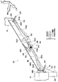
図1において、本実施の形態に係る車体前部構造S1は、車体前部に設けられる機能部品保持部の一例たるラジエータサポート10の周辺の構造に係り、上部支持部材の一例たるラジエータサポートアッパ12と、補強部の一例たるエプロンアッパメンバ14と、連結部材16とを有している。
[First Embodiment]
In FIG. 1, a vehicle body front part structure S1 according to the present embodiment relates to a structure around a
ラジエータサポート10は、車体前部に設けられる機能部品、例えばラジエータ等の熱交換器(図示せず)のための保持部材であって、上部を構成するラジエータサポートアッパ12と、下部を構成するラジエータサポートロワ20と、両側部に立設されるラジエータサポートサイド22とにより、熱交換器を囲む例えば略四角形の枠状に構成されている。
A
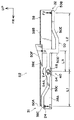
ラジエータサポートアッパ12は、ラジエータサポート10の上部を構成し、車幅方向に沿って配置された部材であって、図示しない熱交換器の上部を保持可能に構成されている。図3に示されるように、ラジエータサポートアッパ12の車幅方向端部には、軸部の一例たるスタッドボルト24が、例えば車幅方向外側に略水平方向に立設されている。
The radiator support upper 12 constitutes an upper portion of the
図1,図3において、エプロンアッパメンバ14は、ラジエータサポートアッパ12より車体後方の車体両側に設けられた強度部材であり、例えば車体前後方向に沿って配設され、フロントサスペンションの取付け部等(図示せず)、車体前部における車幅方向の両側部を補強している。
1 and 3, the apron
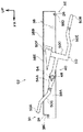
連結部材16は、ラジエータサポートアッパ12と車体両側のエプロンアッパメンバ14とを夫々連結するように配設され、車両下方側への所定以上の荷重を受けた際に、ラジエータサポートアッパ12及びエプロンアッパメンバ14の少なくとも一方から離脱するように構成された強度部材である。図2に示されるように、この連結部材16は、ラジエータサポートアッパ12の車幅方向端部と連結部材16の車体前後方向前端部とを連結するために、車体平面視で例えば略円弧状に形成されている。図3に示されるように、連結部材16の車体前後方向の前端部には、軸部の一例たるスタッドボルト26が、例えば車幅方向外側に略水平方向に立設されている。
The connecting
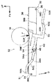
図5において、車体前部のフード28に衝突体18が衝突することを考慮すると、車体前部において該衝突体18が保護される保護領域30は、例えば図2において斜線で示されるように設定される。連結部材16は、車体平面視で該保護領域30とオーバーラップする位置に配設されている。
In FIG. 5, considering that the
図3に示されるように、連結部材16と、ラジエータサポートアッパ12の端部とが連結される第1連結部31において、連結部材16側には、切欠き状の取付け孔16Cを有するフランジ16Aが設けられている。また連結部材16と、エプロンアッパメンバ14の前端とが連結される第2連結部32において、連結部材16側には、切欠き状の取付け孔16Dを有するフランジ16Bが設けられている。第1連結部31におけるフランジ16Aを例に採って説明すると、図4において、取付け孔16Cには、スタッドボルト24が挿通され、該スタッドボルト24は該取付け孔16Cの切欠き方向に相対移動可能となっている。
As shown in FIG. 3, in the first connecting
具体的には、ENCAP及びJNCAP(欧州及び日本の自動車アセスメント)における各々の歩行者頭部保護性能テストで規定される衝撃角度、即ち頭部インパクタが射出機から射出される角度が、セダン型車両の場合に水平方向線HLから夫々50°,65°であることから、取付け孔16Cの切欠き方向もこれらの両角度に対応するように設定されている。即ちフランジ16Aがスタッドボルト24から離脱できる方向は、水平方向線HLから車両下方かつ車両後方側へ、50乃至65°の範囲に設定されている。図3において、第2連結部32におけるフランジ16Bの取付け孔16Dについても同様である。なお、取付け孔16Cの切欠き方向は、上記の角度範囲に限られるものではなく、頭部インパクタの衝撃角度は、車種によって異なるので、車種に応じて他の角度範囲を選択してもよい。
Specifically, the impact angle defined in each pedestrian head protection performance test in ENCAP and JNCAP (Europe and Japan Car Assessment), that is, the angle at which the head impactor is ejected from the injector is a sedan type vehicle. In this case, since the angle is 50 ° and 65 ° from the horizontal direction line HL, the notch direction of the
図3に示されるように、スタッドボルト24,26には、保持手段の一例たるナット34,36が締結される。第1連結部31において連結部材16がラジエータサポートアッパ12から離脱する所定の荷重、即ち離脱荷重は、ナット34の締付けトルクにより調整され、第2連結部32において連結部材16がエプロンアッパメンバ14から離脱する離脱荷重は、ナット36の締付けトルクにより調整される。
As shown in FIG. 3,
(作用)
本実施形態は、上記のように構成されており、以下その作用について説明する。図1において、車体前部構造S1では、ラジエータサポートアッパ12とエプロンアッパメンバ14とが、連結部材16により連結されているので、車体前部のボデー剛性がより向上している。一般にエプロンアッパメンバ14付近は、フロントサスペンション(図示せず)の取付け部となっているが、連結部材16によりラジエータサポートアッパ12とエプロンアッパメンバ14とが連結されているので、片側のタイヤ(図示せず)からサスペンションを通じてエプロンアッパメンバ14に入力された荷重を、反対側のエプロンアッパメンバ14へ伝達でき、これにより車体のねじれを抑制することができる。また前面衝突時に、ラジエータサポートアッパ12が車両の前面から荷重を受けた場合には、連結部材16を介してエプロンアッパメンバ14へ該荷重を伝達することができる。
(Function)
This embodiment is configured as described above, and the operation thereof will be described below. In FIG. 1, in the vehicle body front structure S <b> 1, the radiator support upper 12 and the apron
次に、図5において、連結部材16の部位、例えば第1連結部31におけるフード28に対して衝突体18が衝突した場合について説明する。フード28を介して連結部材16に伝達される衝突体18からの衝突荷重Fが、ナット34の締付けトルクにより設定される所定の離脱荷重以上であり、かつ衝撃角度が略50乃至65°である場合、フランジ16Aはスタッドボルト24から離脱する方向に移動する。そしてスタッドボルト24がフランジ16Aの取付け孔16Cから相対的に抜けることで、スタッドボルト24及びナット34によるフランジ16Aの保持が解除されて、連結部材16がラジエータサポートアッパ12から離脱する。
Next, in FIG. 5, a case where the
第2連結部32におけるフランジ16Bの離脱についても同様であり、第1連結部31及び第2連結部32の少なくとも一方において連結部材16が離脱することで、ラジエータサポートアッパ12より車幅方向外側の部位、即ち該連結部材16の部位におけるフード28の変形ストロークをより多く確保することが可能である。
The same applies to the detachment of the
[第2実施形態]
図6において、本実施の形態に係る車体前部構造S2は、連結部材38の保持手段として、ロック機構40を有している。
[Second Embodiment]
In FIG. 6, the vehicle body front structure S <b> 2 according to the present embodiment has a
連結部材38は、例えば断面L字形の強度部材であり、その縦壁部38Aの前端には車両上方向が開放された取付け孔38Cが設けられ、縦壁部38Aの後端には車両下方向が開放された取付け孔38Dが設けられている。
The connecting
図6に示されるように、ラジエータサポートアッパ12の車幅方向両端部には、車幅方向外側の斜め前方を向いた取付け面42が設けられており、該取付け面42にはスタッドボルト24が夫々立設されている。一方、エプロンアッパメンバ14の前端にも、車幅方向外側の斜め前方を向いた取付け面44が設けられており、該取付け面44にスタッドボルト26が立設されている。連結部材38は、取付け面42,44間に掛け渡されるように取り付けられており、第1連結部31において取付け孔38Cがスタッドボルト24に係合し、第2連結部32において取付け孔38Dがスタッドボルト26に係合している。なお、スタッドボルト24,26の代わりに、同様の外径を有するピン(図示せず)を取付け面42,44に立設するようにしてもよい。
As shown in FIG. 6, both ends of the radiator support upper 12 in the vehicle width direction are provided with mounting
ロック機構40は、連結部材38に対する車両下方側への荷重が所定値未満の場合にスタッドボルト24が取付け孔38Cから離脱しないように規制すると共に、該荷重が所定値以上の場合に該規制を解除するように構成されている。具体的には、連結部材38の縦壁部38Aには、ナット46が固着されており、該ナット46には左ねじを有するボルト48が締結されている。該ボルト48には、前端50Aがスタッドボルト24の位置まで延びると共に、後端50Bがスタッドボルト26の位置まで延びるリンク50が、軸受52を介して回動自在に取り付けられている。なお、ボルト48のねじ部に左ねじが用いられるのは、図示されている車幅方向左側のロック機構40の場合であり、車幅方向右側のロック機構(図示せず)には右ねじが用いられる。
The
図7に示されるように、リンク50は、前端50Aからボルト48の車両後方位置まで延びる前部50Cと、該前部50Cの後端に連結され略車両上下方向に延びる中間部50Dと、該中間部50Dの下端から後端50Bまで延びる後部50Eと、中間部50Dの上端に設けられたトリガ50Fとを有している。図6,図8に示されるように、トリガ50Fは、通常使用時において、連結部材38の上面38Bに設けられた貫通孔38Eを通じて該上面38Bの上側に突出しており、該トリガ50Fの上面は前端50Aに向かって車両下方に傾斜している。このように傾斜を設けているのは、ENCAP及びJNCAPにおける頭部インパクタの衝撃角度を考慮したものである。
As shown in FIG. 7, the
ボルト48の同軸上には、一端(図示せず)が該スタッドボルト24に係止されると共に、他端54Aがリンク50に係止される例えばねじりコイルばね54が設けられており、ボルト48の締付けトルクに対応した付勢力を、リンク50に付与できるように構成されている。即ち、ボルト48の締付けトルクの調整により、ロック機構40の規制が解除される離脱荷重を設定できるようになっている。なお、ねじりコイルばね54の付勢力によりボルト48が緩まないように、例えばボルト48を所謂ダブルナットで締結したり、螺合部を接着剤で固定したりすることが望ましい。
On the same axis as the
他の部分については、第1実施形態と同様であるので、同一の部分には図面に同一の符号を付し、説明を省略する。 Since other parts are the same as those in the first embodiment, the same parts are denoted by the same reference numerals in the drawings, and the description thereof is omitted.
(作用)
本実施形態は、上記のように構成されており、以下その作用について説明する。まず図7,図8において、ロック機構40による離脱荷重の設定について説明する。図7に示されるように、ボルト48の締め付けが行われていないときには、ねじりコイルばね54が略自由状態にあり、リンク50の前端50Aがスタッドボルト24から離間して車両上方に位置すると共に、後端50Bがスタッドボルト26から離間して車両下方に位置し、トリガ50Fが貫通孔38E内に落ち込んだ状態となっている。
(Function)
This embodiment is configured as described above, and the operation thereof will be described below. First, referring to FIGS. 7 and 8, the setting of the separation load by the
ここで、ねじ部が左ねじであるボルト48を締め付けて行くと、図8に示されるように、リンク50が、ねじりコイルばね54を介して、該ボルト48を中心として紙面反時計回りに揺動する。これにより、リンク50の前端50Aがスタッドボルト24に対して車両上方から近接又は当接し、該スタッドボルト24が連結部材38の取付け孔38C内に保持されると共に、リンク50の後端50Bがスタッドボルト26に対して車両下方から近接又は当接し、該スタッドボルト26が連結部材38の取付け孔38D内に保持された状態となる。
Here, when the
図8において、このときのボルト48の締付けトルクTに基づくねじりコイルばね54の付勢力により、リンク50には紙面反時計回りのモーメントM=F1×L1+F2×L2が生じる(図示せず)。ここで、車両の通常使用時の振動等によりリンク50に作用する紙面時計回りのモーメントをM0(図示せず)すると、通常使用時にロック機構40によるスタッドボルト24,26の規制が解除されないようにするために、締付けトルクTは、M0<Mの関係が満たされるように設定される。また図9に示されるように、衝突体18の衝突時には、衝突荷重Fがトリガ50Fに入力されるので、図8において、リンク50にはモーメントMC=F×L3が紙面時計回りに作用する(図示せず)。このときに、ねじりコイルばね54の付勢力に抗してリンク50を紙面時計回りに揺動させ、前端50A及び後端50Bでのスタッドボルト24,26の規制を解除するために、締付けトルクTは、M<MCの関係が満たされるように設定される。
In FIG. 8, a biasing force of the
ボルト48の締付けトルクTを上記のように調整することにより、連結部材38に対して車両下方側への所定以上の荷重が作用しない状態、即ち車両の通常使用時の振動等では、ロック機構40によるスタッドボルト24,26の規制が解除されることはなく、連結部材38によるラジエータサポートアッパ12とエプロンアッパメンバ14との連結状態が維持される。これにより、車体前部の剛性を高めて該車体のねじれ変形を抑制することができ、また前面衝突時には、その衝突荷重を、ラジエータサポートアッパ12から連結部材38を介してエプロンアッパメンバ14へ伝達することができる。
By adjusting the tightening torque T of the
次に、図9において、衝突体18からの衝突荷重Fがリンク50に作用した場合の作用について説明する。車体前部構造S2では、トリガ50Fに衝突荷重Fが入力されると、リンク50が、ねじりコイルばね54の付勢力に抗して紙面時計回りに揺動し、前端50Aがスタッドボルト24の車両上方に移動すると共に、後端50Bがスタッドボルト26の車両下方に移動する。これにより、ロック機構40によるスタッドボルト24,26の規制が解除されるので、連結部材38は、自重又は衝突荷重Fにより、第2連結部32におけるスタッドボルト26を中心して矢印D方向、即ち車両下方に回動し、第1連結部31における連結部材38の前端がスタッドボルト24から離脱する。このようにして、車体前部構造S2では、ラジエータサポートアッパ12より車幅方向外側の部位、即ち連結部材38の部位において、フード(図示せず)の変形ストロークをより多く確保して、衝突荷重Fを柔軟に受け止めることが可能である。
Next, the operation when the collision load F from the
上記各実施形態では、連結部材16,38が所定以上の荷重が入力された際に離脱するので、フード28と該連結部材16,38との間に該フード28の変形ストローク確保用の隙間を設けておく必要性が少ない。このため、車両のデザイン上の制約を少なくすることができ、例えばフード28の高さをより低くすることが可能である。
In each of the above embodiments, since the connecting
なお、本実施形態では、衝突体18の衝突時に、第1連結部31におけるラジエータサポートアッパ12と連結部材38との連結が解除されるものとしたが、これに限られるものではなく、第2連結部32における連結部材38とエプロンアッパメンバ14との連結が解除されるようにしてもよい。また第1連結部31及び第2連結部32の双方における連結が解除されるように構成してもよい。
In the present embodiment, the connection between the radiator support upper 12 and the connecting
また上記各実施形態において、機能部品保持部の一例としてラジエータサポート10を挙げ、上部支持部材の一例としてラジエータサポートアッパ12を挙げたが、何れもこれらの部品に限られるものではない。同様に、補強部についても、エプロンアッパメンバ14に限られるものではない。
Further, in each of the above embodiments, the
10 ラジエータサポート(機能部品保持部)
12 ラジエータサポートアッパ(上部支持部材)
14 エプロンアッパメンバ(補強部)
16 連結部材
16C 取付け孔
16D 取付け孔
24 スタッドボルト(軸部)
26 スタッドボルト(軸部)
31 第1連結部
32 第2連結部
34 ナット
36 ナット
38 連結部材
38C 取付け孔
38D 取付け孔
40 ロック機構
S1 車体前部構造
S2 車体前部構造
10 Radiator support (functional component holder)
12 Radiator support upper (upper support member)
14 Apron upper member (reinforcement part)
16 Connecting
26 Stud bolt (shaft)
31
Claims (4)
該上部支持部材より車体後方の車体両側に設けられた補強部と、
前記上部支持部材と前記車体両側の補強部とを夫々連結するように配設され、車両下方側への所定以上の荷重を受けた際に、前記上部支持部材及び前記補強部の少なくとも一方から離脱する連結部材と、
を有することを特徴とする車体前部構造。 An upper support member that forms the upper part of the functional component holding part provided in the front part of the vehicle body and is disposed along the vehicle width direction;
Reinforcing portions provided on both sides of the vehicle body behind the upper support member;
The upper support member and the reinforcing portions on both sides of the vehicle body are arranged so as to be connected to each other, and detached from at least one of the upper support member and the reinforcing portion when receiving a load exceeding a predetermined value on the vehicle lower side. A connecting member to be
The vehicle body front part structure characterized by having.
互いに連結される部材の他方には、前記取付け孔に挿通されると共に該取付け孔の切欠き方向に相対移動可能な軸部が設けられ、
前記連結部材に対して前記車両下方側への所定以上の荷重が作用しない状態において前記軸部を前記取付け孔内に保持する保持手段を有することを特徴とする請求項1に記載の車体前部構造。 One of the members connected to each other in the first connecting portion where the both ends in the vehicle width direction of the upper support member and the connecting member are connected, and the second connecting portion where the connecting member and the reinforcing portion are connected Is provided with a notch-shaped mounting hole that allows the connection member to be detached to the vehicle lower side,
The other of the members connected to each other is provided with a shaft portion that is inserted into the mounting hole and is relatively movable in the notch direction of the mounting hole,
The vehicle body front portion according to claim 1, further comprising holding means for holding the shaft portion in the mounting hole in a state where a load exceeding a predetermined amount does not act on the connecting member on the vehicle lower side. Construction.
前記保持手段は、前記スタッドボルトに締結され、前記取付け孔の周縁部を前記他方の部材との間に保持するナットであることを特徴とする請求項2に記載の車体前部構造。 The shaft portion is a stud stud bolt,
The vehicle body front part structure according to claim 2, wherein the holding means is a nut that is fastened to the stud bolt and holds a peripheral edge portion of the mounting hole between the other member.
Priority Applications (1)
| Application Number | Priority Date | Filing Date | Title |
|---|---|---|---|
| JP2006166512A JP2007331614A (en) | 2006-06-15 | 2006-06-15 | Body front structure |
Applications Claiming Priority (1)
| Application Number | Priority Date | Filing Date | Title |
|---|---|---|---|
| JP2006166512A JP2007331614A (en) | 2006-06-15 | 2006-06-15 | Body front structure |
Publications (1)
| Publication Number | Publication Date |
|---|---|
| JP2007331614A true JP2007331614A (en) | 2007-12-27 |
Family
ID=38931492
Family Applications (1)
| Application Number | Title | Priority Date | Filing Date |
|---|---|---|---|
| JP2006166512A Pending JP2007331614A (en) | 2006-06-15 | 2006-06-15 | Body front structure |
Country Status (1)
| Country | Link |
|---|---|
| JP (1) | JP2007331614A (en) |
Cited By (5)
| Publication number | Priority date | Publication date | Assignee | Title |
|---|---|---|---|---|
| JP2010215125A (en) * | 2009-03-17 | 2010-09-30 | Honda Motor Co Ltd | Joint structure of vehicle body frame member |
| JP2011218912A (en) * | 2010-04-07 | 2011-11-04 | Honda Motor Co Ltd | Pedestrian protection device for vehicle |
| WO2014033523A1 (en) | 2012-08-30 | 2014-03-06 | Toyota Jidosha Kabushiki Kaisha | Vehicle body front structure |
| JP2014108773A (en) * | 2012-12-04 | 2014-06-12 | Toyoda Iron Works Co Ltd | Vehicular front frame structure |
| DE102018117610A1 (en) | 2017-07-28 | 2019-01-31 | Toyota Jidosha Kabushiki Kaisha | Reinforcement structure on a front side of a vehicle cabin |
-
2006
- 2006-06-15 JP JP2006166512A patent/JP2007331614A/en active Pending
Cited By (8)
| Publication number | Priority date | Publication date | Assignee | Title |
|---|---|---|---|---|
| JP2010215125A (en) * | 2009-03-17 | 2010-09-30 | Honda Motor Co Ltd | Joint structure of vehicle body frame member |
| JP2011218912A (en) * | 2010-04-07 | 2011-11-04 | Honda Motor Co Ltd | Pedestrian protection device for vehicle |
| WO2014033523A1 (en) | 2012-08-30 | 2014-03-06 | Toyota Jidosha Kabushiki Kaisha | Vehicle body front structure |
| US9302712B2 (en) | 2012-08-30 | 2016-04-05 | Toyota Jidosha Kabushiki Kaisha | Vehicle body front structure |
| JP2014108773A (en) * | 2012-12-04 | 2014-06-12 | Toyoda Iron Works Co Ltd | Vehicular front frame structure |
| DE102018117610A1 (en) | 2017-07-28 | 2019-01-31 | Toyota Jidosha Kabushiki Kaisha | Reinforcement structure on a front side of a vehicle cabin |
| US10464614B2 (en) | 2017-07-28 | 2019-11-05 | Toyota Jidosha Kabushiki Kaisha | Reinforcement structure at front side of vehicle cabin |
| DE102018117610B4 (en) | 2017-07-28 | 2022-11-10 | Toyota Jidosha Kabushiki Kaisha | Reinforcement structure at a front of a vehicle cabin |
Similar Documents
| Publication | Publication Date | Title |
|---|---|---|
| JP4488047B2 (en) | Lamp mounting structure | |
| US9233662B2 (en) | Vehicle-body front structure of vehicle | |
| US8220576B2 (en) | Front end structure for automobile | |
| US10596994B2 (en) | Front structure of vehicle | |
| JP7079147B2 (en) | Steering column | |
| JP4721404B2 (en) | Mount structure for vehicle power unit | |
| WO2014069113A1 (en) | Fender support structure | |
| JP5883159B2 (en) | Vehicle construction method to prevent battery damage during rear impact using optimized bracket separation | |
| JP4736609B2 (en) | Car fender panel mounting structure | |
| JP3788039B2 (en) | Shock absorbing steering column device | |
| JP2007331614A (en) | Body front structure | |
| JP2005161888A (en) | Body front structure | |
| JP2012011977A (en) | Front structure of vehicle | |
| JP5320005B2 (en) | Fender panel mounting bracket | |
| JP2005335668A (en) | Cooling system support structure for vehicles | |
| US20140021745A1 (en) | Releasable tunnel brace for a vehicle | |
| JP2687766B2 (en) | Pedestrian protection device for automobiles | |
| JP7750135B2 (en) | Back door lock structure | |
| JP4466150B2 (en) | Car suspension mounting structure | |
| JP7129749B2 (en) | vehicle structure | |
| US20250162655A1 (en) | Vehicle hood and bracket | |
| JP5857926B2 (en) | Seat back striker mounting structure | |
| JP5262268B2 (en) | Door structure | |
| JP2009096352A (en) | Vehicle component mounting structure | |
| KR20070103929A (en) | Vehicle fuel tank mounting structure |