JP2007327422A - Fuel injection control device for internal combustion engine - Google Patents
Fuel injection control device for internal combustion engine Download PDFInfo
- Publication number
- JP2007327422A JP2007327422A JP2006159614A JP2006159614A JP2007327422A JP 2007327422 A JP2007327422 A JP 2007327422A JP 2006159614 A JP2006159614 A JP 2006159614A JP 2006159614 A JP2006159614 A JP 2006159614A JP 2007327422 A JP2007327422 A JP 2007327422A
- Authority
- JP
- Japan
- Prior art keywords
- fuel
- amount
- fuel injection
- predetermined
- kinematic viscosity
- Prior art date
- Legal status (The legal status is an assumption and is not a legal conclusion. Google has not performed a legal analysis and makes no representation as to the accuracy of the status listed.)
- Withdrawn
Links
Images
Landscapes
- Electrical Control Of Air Or Fuel Supplied To Internal-Combustion Engine (AREA)
- Combined Controls Of Internal Combustion Engines (AREA)
Abstract
Description
本発明は、内燃機関の燃料噴射制御装置に関する。 The present invention relates to a fuel injection control device for an internal combustion engine.
特許文献1にディーゼルエンジンの燃料噴射制御装置が記載されている。特許文献1によれば、ディーゼルエンジンが始動されるときに燃料噴射弁から噴射される燃料の粘性が低いと、洩流量が多くなり、その結果、燃料噴射弁から噴射される燃料の量が目標量よりも少なくなる。そして、特許文献1に記載された燃料噴射制御装置では、燃料の粘性が低いときには、燃料噴射弁から噴射される燃料の量を目標量に制御するために、燃料噴射弁から噴射させる燃料の量を増量するようにしている。 Patent Document 1 describes a fuel injection control device for a diesel engine. According to Patent Document 1, when the viscosity of the fuel injected from the fuel injection valve is low when the diesel engine is started, the leakage flow rate increases, and as a result, the amount of fuel injected from the fuel injection valve becomes the target. Less than the amount. In the fuel injection control device described in Patent Document 1, when the viscosity of the fuel is low, the amount of fuel injected from the fuel injection valve in order to control the amount of fuel injected from the fuel injection valve to a target amount. The amount is increased.
ところで、圧縮着火式の内燃機関を始動させようとするときには、一般的に、燃料噴射弁から比較的多くの燃料を噴射させる。そして、圧縮着火式の内燃機関の始動に関しては、クランキングの開始から始めて燃焼が開始するまでにかかる時間を機関始動時間と称したとき、機関始動時間が短いほうが好ましいが、あまり短い必要はない。ここで、機関始動時間が短いということは、燃料噴射弁から噴射する燃料の量(以下「燃料噴射量」という)を少なくしたとしても、機関始動時間は、或る一定の時間内に収まることを意味している。一方、機関始動時間が長いということは、燃料噴射量を多くしなければ、機関始動時間が或る一定の時間内に収まらないことを意味している。 By the way, when a compression ignition type internal combustion engine is to be started, a relatively large amount of fuel is generally injected from a fuel injection valve. Regarding the start of the compression ignition type internal combustion engine, when the time required from the start of cranking to the start of combustion is referred to as the engine start time, it is preferable that the engine start time is short, but it is not necessary to be so short. . Here, the short engine start time means that even if the amount of fuel injected from the fuel injection valve (hereinafter referred to as “fuel injection amount”) is reduced, the engine start time is within a certain time. Means. On the other hand, a long engine start time means that the engine start time does not fall within a certain time unless the fuel injection amount is increased.
いずれにしても、機関始動時間が或る一定の時間であれば十分であり、また、内燃機関の分野では、燃費をできるだけ向上させることが要請されることから、機関始動時間が短くなることが予想されたときには、燃料噴射量を少なくしたほうが好ましい。もちろん、機関始動時間が長くなることが予想されたときには、燃料噴射量を多くして、機関始動時間が或る一定の時間内に収まるようにする必要がある。 In any case, it is sufficient that the engine start time is a certain time, and in the field of internal combustion engines, it is required to improve the fuel consumption as much as possible, so the engine start time may be shortened. When expected, it is preferable to reduce the fuel injection amount. Of course, when the engine start time is expected to be long, it is necessary to increase the fuel injection amount so that the engine start time is within a certain time.
本発明の目的は、内燃機関を始動させようとしたときに機関始動時間を目標とする機関始動時間の少なくとも近傍に制御すると共に燃費の向上を図ることにある。 An object of the present invention is to control the engine start time at least in the vicinity of the target engine start time when attempting to start the internal combustion engine and to improve fuel consumption.
上記課題を解決するために、1番目の発明では、燃料噴射弁から噴射される燃料の動粘度が予め定められた動粘度であるときに内燃機関を始動させようとしてから予め定められた時間で燃焼を開始させることができる燃料の量を目標燃料量として該目標燃料量の燃料を燃料噴射弁から噴射する内燃機関の燃料噴射制御装置において、燃料の動粘度が前記予め定められた動粘度よりも低いときには燃料噴射弁から噴射する燃料の量を前記目標燃料量よりも少なくすると共に、燃料の動粘度が前記予め定められた動粘度よりも高いときには燃料噴射弁から噴射する燃料の量を前記目標燃料量よりも多くする。 In order to solve the above problem, in the first invention, when the kinematic viscosity of the fuel injected from the fuel injection valve is a predetermined kinematic viscosity, the internal combustion engine is started for a predetermined time from the start. In a fuel injection control device for an internal combustion engine that injects fuel of a target fuel amount from a fuel injection valve using a fuel amount that can start combustion as a target fuel amount, the dynamic viscosity of the fuel is greater than the predetermined dynamic viscosity. Is lower than the target fuel amount, and when the kinematic viscosity of the fuel is higher than the predetermined kinematic viscosity, the amount of fuel injected from the fuel injection valve is reduced. Increase the target fuel amount.
上記課題を解決するために、2番目の発明では、燃料噴射弁から噴射される燃料の圧力を予め定められた圧力に制御すると共に、燃料噴射弁から噴射される燃料の動粘度が予め定められた動粘度であるときに内燃機関を始動させようとしてから予め定められた時間で燃焼を開始させることができる燃料の量を目標燃料量として該目標燃料量の燃料を燃料噴射弁から噴射する内燃機関の燃料噴射制御装置において、燃料の動粘度が前記予め定められた動粘度よりも低いときには燃料噴射弁から噴射する燃料の圧力を前記予め定められた圧力よりも低くすると共に、燃料の動粘度が前記予め定められた動粘度よりも高いときには燃料噴射弁から噴射する燃料の圧力を前記予め定められた圧力よりも高くする。 In order to solve the above problems, in the second invention, the pressure of the fuel injected from the fuel injection valve is controlled to a predetermined pressure, and the kinematic viscosity of the fuel injected from the fuel injection valve is determined in advance. An internal combustion engine that injects fuel of the target fuel amount from the fuel injection valve with the amount of fuel that can start combustion in a predetermined time after starting to start the internal combustion engine when the kinematic viscosity is In the engine fuel injection control device, when the dynamic viscosity of the fuel is lower than the predetermined dynamic viscosity, the pressure of the fuel injected from the fuel injection valve is made lower than the predetermined pressure, and the dynamic viscosity of the fuel Is higher than the predetermined kinematic viscosity, the pressure of the fuel injected from the fuel injection valve is made higher than the predetermined pressure.
1番目の発明によれば、内燃機関を始動させようとしたときに内燃機関を始動させようとしてから燃焼が開始するまでの時間が予め定められた時間の少なくとも近傍に制御されると共に、燃費が向上する。すなわち、燃料の動粘度が低いときには内燃機関を始動させようとしてから燃焼が開始するまでにかかる時間が短くなる傾向にあるが、このとき、1番目の発明によれば、燃料噴射弁から噴射する燃料の量を少なくするので、内燃機関を始動させようとしてから燃焼が開始するまでの時間が予め定められた時間の少なくとも近傍に制御されると共に、燃料噴射弁から噴射する燃料の量を少なくした分だけ燃費が向上する。一方、燃料の動粘度が高いときには内燃機関を始動させようとしてから燃焼が開始するまでにかかる時間が長くなる傾向にあるが、このとき、1番目の発明によれば、燃料噴射弁から噴射する燃料の量を多くするので、少なくとも、内燃機関を開始させようとしてから燃焼が開始するまでの時間が予め定められた時間の少なくとも近傍に制御される。 According to the first invention, when the internal combustion engine is started, the time from the start of the internal combustion engine to the start of combustion is controlled to be at least in the vicinity of a predetermined time, and the fuel consumption is reduced. improves. That is, when the kinematic viscosity of the fuel is low, there is a tendency that the time required from the start of the internal combustion engine to the start of combustion tends to be short. At this time, according to the first invention, the fuel is injected from the fuel injection valve. Since the amount of fuel is reduced, the time from the start of the internal combustion engine to the start of combustion is controlled at least in the vicinity of a predetermined time, and the amount of fuel injected from the fuel injection valve is reduced. Fuel consumption is improved by that amount. On the other hand, when the kinematic viscosity of the fuel is high, there is a tendency that the time required from the start of the internal combustion engine to the start of combustion tends to be long. At this time, according to the first invention, the fuel is injected from the fuel injection valve. Since the amount of fuel is increased, at least the time from the start of the internal combustion engine to the start of combustion is controlled to be at least in the vicinity of a predetermined time.
また、2番目の発明によれば、内燃機関を始動させようとしたときに内燃機関を始動させようとしてから燃焼が開始するまでの時間が予め定められた時間の少なくとも近傍に制御されると共に、燃費が向上する。すなわち、燃料の動粘度が低いときには内燃機関を始動させようとしてから燃焼が開始するまでにかかる時間が短くなる傾向にあるが、このとき、2番目の発明によれば、燃料噴射弁から噴射する燃料の圧力を低くするので、燃料噴射弁から噴射される燃料の量が少なくなり、その結果、内燃機関を始動させようとしてから燃焼が開始するまでの時間が予め定められた時間の少なくとも近傍に制御されると共に、燃料噴射弁から噴射する燃料の量が少なくなる分だけ燃費が向上する。一方、燃料の動粘度が高いときには内燃機関を始動させようとしてから燃焼が開始するまでにかかる時間が長くなる傾向にあるが、このとき、2番目の発明によれば、燃料噴射弁から噴射する燃料の圧力を高くするので、燃料噴射弁から噴射される燃料の量が多くなり、その結果、少なくとも、内燃機関を始動させようとしてから燃焼が開始するまでの時間が予め定められた時間の少なくとも近傍に制御される。 According to the second invention, when the internal combustion engine is started, the time from the start of the internal combustion engine to the start of combustion is controlled to be at least in the vicinity of a predetermined time, Fuel consumption is improved. That is, when the kinematic viscosity of the fuel is low, there is a tendency that the time taken from the start of the internal combustion engine to the start of combustion tends to be short. At this time, according to the second invention, the fuel is injected from the fuel injection valve. Since the fuel pressure is lowered, the amount of fuel injected from the fuel injection valve is reduced. As a result, the time from the start of the internal combustion engine to the start of combustion is at least in the vicinity of the predetermined time. In addition to being controlled, the fuel consumption is improved by the amount of fuel injected from the fuel injection valve. On the other hand, when the kinematic viscosity of the fuel is high, it tends to take a long time to start combustion after trying to start the internal combustion engine. At this time, according to the second invention, the fuel is injected from the fuel injection valve. Since the pressure of the fuel is increased, the amount of fuel injected from the fuel injection valve increases, and as a result, at least the time from the start of the internal combustion engine to the start of combustion is at least a predetermined time Controlled in the vicinity.
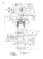
以下、図面を参照して本発明の実施の形態について説明する。図1は、本発明の燃料噴射制御装置を備えた内燃機関を示している。図1に示した内燃機関は、圧縮着火式の内燃機関である。図1において、1は機関本体、2はシリンダブロック、3はシリンダヘッド、4はピストン、5は燃焼室、6は電気制御式の燃料噴射弁、7は吸気弁、8は吸気ポート、9は排気弁、10は排気ポートをそれぞれ示している。燃料噴射弁6は、燃料を燃焼室5内に直接噴射する。また、吸気ポート8は、対応する吸気枝管11を介してサージタンク12に連結されている。サージタンク12は、吸気ダクト13およびインタークーラ14を介して過給機15のコンプレッサ16の出口部に連結されている。コンプレッサ16の入口部は、吸気管17を介してエアクリーナ18に連結されている。また、吸気管17内には、ステップモータ19によって駆動されるスロットル弁20が配置されている。また、スロットル弁20上流の吸気管17には、燃焼室5内に吸入される空気の質量流量を検出するための質量流量検出器21が配置されている。
Embodiments of the present invention will be described below with reference to the drawings. FIG. 1 shows an internal combustion engine equipped with a fuel injection control device of the present invention. The internal combustion engine shown in FIG. 1 is a compression ignition type internal combustion engine. In FIG. 1, 1 is an engine body, 2 is a cylinder block, 3 is a cylinder head, 4 is a piston, 5 is a combustion chamber, 6 is an electrically controlled fuel injection valve, 7 is an intake valve, 8 is an intake port, and 9 is Exhaust valves and 10 indicate exhaust ports, respectively. The
一方、排気ポート10は、排気マニホルド22を介して過給機15の排気タービン23の入口部に連結されている。排気タービン23の出口部は、排気管24を介してパティキュレートフィルタ25を内蔵したケーシング26に連結されている。排気マニホルド22には、空燃比センサ27が取り付けられている。
On the other hand, the
また、ケーシング26の出口部に連結された排気管28とスロットル弁20下流の吸気管17とは、排気ガス再循環(以下「EGR」という)通路29を介して互いに連結される。EGR通路29内には、ステップモータ30によって駆動されるEGR制御弁31が配置される。また、EGR通路29内には、そこを流れるEGRガスを冷却するインタークーラ32が配置される。図1に示した実施形態では、機関冷却水がインタークーラ32内に導かれ、機関冷却水によりEGRガスが冷却される。
The
また、燃料噴射弁6は、燃料供給管33を介して燃料リザーバ、すなわち、いわゆるコモンレール34に連結されている。コモンレール34内には、電気制御式の吐出量可変な燃料ポンプ35から燃料が供給される。コモンレール34内に供給された燃料は、各燃料供給管33を介して対応する燃料噴射弁6に供給される。コモンレール34には、その中の燃料圧を検出する燃料圧センサ36が取り付けられる。この燃料圧センサ36の出力信号に基づいてコモンレール34内の燃料圧が目標燃料圧となるように燃料ポンプ35の吐出量が制御される。
The
電子制御ユニット40は、デジタルコンピュータからなり、双方向性バス41により互いに接続されたROM(リードオンリメモリ)42、RAM(ランダムアクセスメモリ)43、CPU(マイクロプロセッサ)44、入力ポート45および出力ポート46を具備する。質量流量検出器21、空燃比センサ27、および、燃料圧センサ36の出力信号は、それぞれ、対応するAD変換器47を介して入力ポート45に入力される。アクセルペダル50には、その踏込量に比例した出力電圧を発生する負荷センサ51が接続されている。負荷センサ51の出力電圧は、対応するAD変換器47を介して入力ポート45に入力される。また、入力ポート45には、クランクシャフトが例えば30°回転する毎に出力パルスを発生するクランク角センサ52が接続されている。一方、出力ポート46は、対応する駆動回路48を介して燃料噴射弁6、スロットル弁制御用ステップモータ19、EGR制御弁制御用ステップモータ30、および、燃料ポンプ35に接続され、これらの作動は、電子制御ユニット40により制御される。
The
次に、第1実施形態の燃料噴射制御装置による燃料噴射制御について説明する。第1実施形態の燃料噴射制御では、内燃機関を始動させようとしたとき(以下「機関始動時」という)には、基本的には、以下のように燃料噴射弁6から噴射する燃料の量(以下「燃料噴射量」という)を制御する。すなわち、まず、燃料噴射弁6から噴射する燃料の動粘度が予め定められた動粘度(以下「所定動粘度」という)であることを前提にしたときに内燃機関を始動させようとしてから実際に燃焼が開始するまでの時間(以下「機関始動時間」という)が予め定められた時間(以下「所定機関始動時間」という)となる燃料の量を目標燃料量として実験等によって予め求めておく。そして、機関始動時、燃料噴射弁6から上記目標燃料量の燃料が噴射されるように燃料噴射弁6の開弁時間を制御する。これによれば、燃料の動粘度が所定動粘度であれば、内燃機関を始動させようとしてから所定機関始動時間で燃焼が開始される、すなわち、内燃機関が始動することになる。
Next, fuel injection control by the fuel injection control device of the first embodiment will be described. In the fuel injection control of the first embodiment, when an internal combustion engine is to be started (hereinafter referred to as “engine start”), the amount of fuel injected from the
なお、上述した実施形態では、目標燃料量を求める際に燃料の動粘度のみを考慮しているが、これに加えて外気温度を考慮し、燃料の動粘度と外気温度との関数でもって目標燃料量を求めてもよい。 In the above-described embodiment, only the kinematic viscosity of the fuel is taken into account when obtaining the target fuel amount, but in addition to this, the outside air temperature is taken into consideration, and the target is obtained as a function of the kinematic viscosity of the fuel and the outside air temperature. The amount of fuel may be obtained.
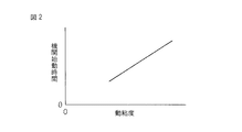
ところで、上述したように、機関始動時、燃料噴射量を上記目標燃料量に制御したときに機関始動時間が所定機関始動時間になるのは、燃料の動粘度が所定動粘度である場合である。したがって、燃料の動粘度が所定動粘度でない場合には、機関始動時に燃料噴射量を上記目標燃料量に制御したとしても、機関始動時間は、所定機関始動時間にならない。詳細には、動粘度が所定動粘度よりも低い燃料は、動粘度が所定動粘度である燃料に比べて気化しやすい。このため、機関始動時、燃料噴射量を上記目標燃料量に制御すると、機関始動時間は、所定機関始動時間よりも短くなる。一方、動粘度が所定動粘度よりも高い燃料は、動粘度が所定動粘度である燃料に比べて気化しづらい。このため、機関始動時、燃料噴射量を上記目標燃料量に制御すると、機関始動時間は、所定機関始動時間よりも長くなる。そして、本願の発明者の研究により、燃料の動粘度と機関始動時間との間には、図2に示したように或る程度の比例関係があることが判明した。 By the way, as described above, the engine start time becomes the predetermined engine start time when the fuel injection amount is controlled to the target fuel amount when the engine is started, when the fuel kinematic viscosity is the predetermined kinematic viscosity. . Therefore, when the kinematic viscosity of the fuel is not the predetermined kinematic viscosity, the engine start time does not become the predetermined engine start time even if the fuel injection amount is controlled to the target fuel amount at the time of engine start. Specifically, a fuel having a kinematic viscosity lower than a predetermined kinematic viscosity is more easily vaporized than a fuel having a kinematic viscosity having a predetermined kinematic viscosity. For this reason, if the fuel injection amount is controlled to the target fuel amount when the engine is started, the engine start time becomes shorter than the predetermined engine start time. On the other hand, a fuel having a kinematic viscosity higher than a predetermined kinematic viscosity is less likely to be vaporized than a fuel having a kinematic viscosity having a predetermined kinematic viscosity. For this reason, if the fuel injection amount is controlled to the target fuel amount at the time of engine start, the engine start time becomes longer than the predetermined engine start time. As a result of research by the inventors of the present application, it has been found that there is a certain proportional relationship between the kinematic viscosity of the fuel and the engine start time as shown in FIG.
ここで、機関始動時間が所定機関始動時間よりも長いことは好ましくないが、機関始動時間が所定機関始動時間よりも短い必要はない。すなわち、機関始動時間は、所定機関始動時間程度であれば十分であり、すなわち、機関始動時、内燃機関が所定機関始動時間で始動すれば十分である。そこで、第1実施形態の燃料噴射制御では、燃料の動粘度が所定動粘度よりも低いほど燃料噴射量を上記目標燃料量よりも少なくし、燃料の動粘度が所定動粘度よりも高いほど燃料噴射量を上記目標燃料量よりも多くする。これによれば、燃料の動粘度が所定動粘度よりも低く、機関始動時間が所定機関始動時間よりも短くなる傾向があるときに、燃料噴射量が上記目標燃料量よりも少なくされるので、機関始動時間が所定機関始動時間に制御されるか、或いは、少なくとも所定機関始動時間近傍に制御される。一方、燃料の動粘度が所定動粘度よりも高く、機関始動時間が所定機関始動時間よりも長くなる傾向があるときに、燃料噴射量が上記目標燃料量よりも多くされるので、機関始動時間が所定機関始動時間に制御されるか、或いは、少なくとも所定機関始動時間近傍に制御される。このように、第1実施形態の燃料噴射制御によれば、燃料の動粘度が所定動粘度よりも低いときであっても高いときであっても、機関始動時間が所定機関始動時間に制御されるか、或いは、少なくとも所定機関始動時間近傍に制御される。また、燃料の動粘度が所定動粘度よりも低いときには燃料噴射量を目標燃料量よりも少なくすることから、その分、燃費が向上する。また、燃料の動粘度が所定動粘度よりも低いときには、燃料噴射量を目標燃料量よりも少なくすることから、過剰な量の燃料が燃料噴射弁6から噴射されることがなく、したがって、機関始動時に、燃焼室5から多量のHCが排出されたり白煙や黒煙が排出されたりすることが抑制される。
Here, it is not preferable that the engine start time is longer than the predetermined engine start time, but the engine start time does not have to be shorter than the predetermined engine start time. That is, it is sufficient that the engine start time is about the predetermined engine start time, that is, it is sufficient that the internal combustion engine is started at the predetermined engine start time when the engine is started. Therefore, in the fuel injection control of the first embodiment, the fuel injection amount is set to be smaller than the target fuel amount as the fuel kinematic viscosity is lower than the predetermined kinematic viscosity, and the fuel is increased as the fuel kinematic viscosity is higher than the predetermined kinematic viscosity. The injection amount is made larger than the target fuel amount. According to this, when the fuel kinematic viscosity is lower than the predetermined kinematic viscosity and the engine start time tends to be shorter than the predetermined engine start time, the fuel injection amount is made smaller than the target fuel amount. The engine start time is controlled to a predetermined engine start time, or at least near the predetermined engine start time. On the other hand, when the fuel kinematic viscosity is higher than the predetermined kinematic viscosity and the engine start time tends to be longer than the predetermined engine start time, the fuel injection amount is made larger than the target fuel amount. Is controlled at a predetermined engine start time, or at least near the predetermined engine start time. Thus, according to the fuel injection control of the first embodiment, the engine start time is controlled to the predetermined engine start time regardless of whether the fuel kinematic viscosity is lower or higher than the predetermined kinematic viscosity. Alternatively, it is controlled at least near the predetermined engine start time. Further, when the fuel kinematic viscosity is lower than the predetermined kinematic viscosity, the fuel injection amount is made smaller than the target fuel amount, so that the fuel efficiency is improved accordingly. In addition, when the kinematic viscosity of the fuel is lower than the predetermined kinematic viscosity, the fuel injection amount is made smaller than the target fuel amount, so that an excessive amount of fuel is not injected from the
なお、第1実施形態の燃料噴射制御において、機関始動時、燃料の動粘度が所定動粘度よりも低いときには燃料噴射量を上記目標燃料量よりも一定量だけ少なくし、燃料の動粘度が所定動粘度よりも高いときには燃料噴射量を上記目標燃料量よりも一定量だけ多くするようにしてもよい。或いは、第1実施形態の燃料噴射制御において、機関始動時、燃料の動粘度が所定動粘度よりも一定値以上低いほど燃料噴射量を目標燃料よりも少なくし、燃料の動粘度が所定動粘度よりも一定値以上高いほど燃料噴射量を目標燃料よりも多くしてもよい。或いは、第1実施形態の燃料噴射制御において、機関始動時、燃料の動粘度が所定動粘度よりも一定値以上低いときに燃料噴射量を目標燃料量よりも一定量だけ少なくし、燃料の動粘度が所定動粘度よりも一定値以上高いときに燃料噴射量を目標燃料量よりも一定量だけ多くしてもよい。 In the fuel injection control according to the first embodiment, when the engine is started, when the fuel kinematic viscosity is lower than the predetermined kinematic viscosity, the fuel injection amount is decreased by a certain amount from the target fuel amount, and the fuel kinematic viscosity is set to a predetermined value. When it is higher than the kinematic viscosity, the fuel injection amount may be increased by a certain amount from the target fuel amount. Alternatively, in the fuel injection control of the first embodiment, when the engine is started, the fuel injection amount is made smaller than the target fuel as the fuel kinematic viscosity is lower than the predetermined kinematic viscosity by a certain value or more. The fuel injection amount may be made larger than the target fuel as it is higher than a certain value. Alternatively, in the fuel injection control according to the first embodiment, when the engine is started, when the fuel kinematic viscosity is lower than the predetermined kinematic viscosity by a certain value or more, the fuel injection amount is decreased by a certain amount from the target fuel amount, When the viscosity is higher than the predetermined kinematic viscosity by a certain value or more, the fuel injection amount may be increased by a certain amount from the target fuel amount.
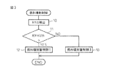
図3は、第1実施形態の燃料噴射制御を実行するルーチンの一例を示している。図3のルーチンでは、始めに、ステップ10において、燃料の動粘度KVが検出される。次いで、ステップ11において、燃料の動粘度KVが所定動粘度KVthである(KV=KVth)であるか否かが判別される。ここで、KV=KVthであると判別されたときには、ステップ12に進んで、燃料噴射量制御Iが実行される。すなわち、ここでは、燃料噴射量が上記目標燃料量となるように燃料噴射弁6の開弁時間が制御される。一方、ステップ11において、KV≠KVthであると判別されたときには、ステップ13に進んで、燃料噴射量制御IIが実行される。すなわち、ここでは、燃料の動粘度KVが所定動粘度KVthよりも低いときには低いほど、燃料噴射量が上記目標燃料量よりも少なくなるように燃料噴射弁6の開弁時間が制御され、燃料の動粘度KVが所定動粘度KVthよりも高いときには高いほど、燃料噴射量が上記目標燃料量よりも多くなるように燃料噴射弁6の開弁時間が制御される。
FIG. 3 shows an example of a routine for executing the fuel injection control of the first embodiment. In the routine of FIG. 3, first, in
次に、第2実施形態の燃料噴射制御について説明する。第2実施形態の燃料噴射制御では、燃料の動粘度が所定動粘度であるときには、第1実施形態の燃料噴射制御と同様に、燃料噴射量が上記目標燃料量となるように燃料噴射弁6の開弁時間を制御する。一方、燃料の動粘度が所定動粘度よりも低いときには低いほど、コモンレール34内の燃料の圧力(すなわち、燃料噴射弁6から噴射される燃料の圧力)が上記目標燃料圧よりも低くなるように燃料ポンプ35の吐出量を制御する。一方、燃料の動粘度が所定動粘度よりも高いときには高いほど、コモンレール34内の燃料の圧力が上記目標燃料圧よりも高くなるように燃料ポンプ35の吐出量を制御する。
Next, fuel injection control of the second embodiment will be described. In the fuel injection control of the second embodiment, when the kinematic viscosity of the fuel is a predetermined kinematic viscosity, as in the fuel injection control of the first embodiment, the
これによれば、燃料の動粘度が所定動粘度よりも低いときには、燃料噴射弁6から噴射される燃料の圧力が低くされるので、燃料噴射量が上記目標燃料量よりも少なくなり、燃料の動粘度が所定動粘度よりも高いときには、燃料噴射弁6から噴射される燃料の圧力が高くされるので、燃料噴射量が上記目標燃料量よりも多くなる。このため、第1実施形態の燃料噴射制御に関連して説明した理由と同じ理由で、燃料の動粘度が所定動粘度よりも低いときであっても高いときであっても、機関始動時間が所定機関始動時間に制御されるか、或いは、少なくとも所定機関始動時間近傍に制御される。また、燃料の動粘度が所定動粘度よりも低いときには燃料噴射量が目標燃料量よりも少なくされることから、その分、燃費が向上する。
According to this, when the kinematic viscosity of the fuel is lower than the predetermined kinematic viscosity, the pressure of the fuel injected from the
なお、第2実施形態の燃料噴射制御において、機関始動時、燃料の動粘度が所定動粘度よりも低いときにはコモンレール34内の燃料の圧力を上記目標燃料圧力よりも一定量だけ低くし、燃料の動粘度が所定動粘度よりも高いときにはコモンレール34内の燃料の圧力を上記目標燃料圧力よりも一定量だけ高くするようにしてもよい。或いは、第2実施形態の燃料噴射制御において、機関始動時、燃料の動粘度が所定動粘度よりも一定値以上低いほどコモンレール34内の燃料の圧力を目標燃料圧力よりも低くし、燃料の動粘度が所定動粘度よりも一定値以上高いほどコモンレール34内の燃料の圧力を目標燃料圧力よりも高くするようにしてもよい。或いは、第2実施形態の燃料噴射制御において、機関始動時、燃料の動粘度が所定動粘度よりも一定値以上低いときにコモンレール34内の圧力を目標燃料圧力よりも一定量だけ低くし、燃料の動粘度が所定動粘度よりも一定値以上高いときにコモンレール34内の圧力を目標燃料圧力よりも一定量だけ高くしてもよい。
In the fuel injection control of the second embodiment, when the dynamic viscosity of the fuel is lower than the predetermined dynamic viscosity at the time of starting the engine, the fuel pressure in the
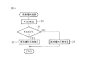
図4は、第2実施形態の燃料噴射制御を実行するルーチンの一例を示している。図4のルーチンでは、始めに、ステップ20において、燃料の動粘度KVが検出される。次いで、ステップ21において、燃料の動粘度KVが所定動粘度KVthである(KV=KVth)であるか否かが判別される。ここで、KV=KVthであると判別されたときには、ステップ22に進んで、燃料噴射圧制御Iが実行される。すなわち、ここでは、コモンレール34内の燃料の圧力(すなわち、燃料噴射量6から噴射される燃料の圧力)が上記目標燃料圧力となるように燃料ポンプ35の吐出量が制御される。一方、ステップ21において、KV≠KVthであると判別されたときには、ステップ23に進んで、燃料噴射圧制御IIが実行される。すなわち、ここでは、燃料の動粘度KVが所定動粘度KVthよりも低いときには低いほど、コモンレール34内の燃料の圧力が上記目標燃料圧力よりも低くなるように燃料ポンプ35の吐出量が制御され、燃料の動粘度KVが所定動粘度KVthよりも高いときには高いほど、コモンレール34内の燃料の圧力が上記目標燃料圧力よりも高くなるように燃料ポンプ35の吐出量が制御される。
FIG. 4 shows an example of a routine for executing the fuel injection control of the second embodiment. In the routine of FIG. 4, first, in
なお、図3および図4のルーチンでは、ステップ11およびステップ21において、燃料の動粘度KVが所定動粘度KVthであるか否かを判別しているが、これに代えて、燃料の動粘度KVが所定動粘度KVthに対して一定値αの範囲内にある(KVth−α<KV<KVth+α)か否かを判別するようにしてもよい。この場合、KVth−α<KV<KVth+αであると判別されたときには、ステップ12またはステップ22に進み、KVth−α<KV<KVth+αではないと判別されたときには、ステップ13またはステップ23に進む。
In the routines of FIGS. 3 and 4, it is determined in
4 ピストン
5 燃焼室
6 燃料噴射弁
7 吸気弁
9 排気弁
34 コモンレール
35 燃料ポンプ
4
Claims (2)
Priority Applications (1)
| Application Number | Priority Date | Filing Date | Title |
|---|---|---|---|
| JP2006159614A JP2007327422A (en) | 2006-06-08 | 2006-06-08 | Fuel injection control device for internal combustion engine |
Applications Claiming Priority (1)
| Application Number | Priority Date | Filing Date | Title |
|---|---|---|---|
| JP2006159614A JP2007327422A (en) | 2006-06-08 | 2006-06-08 | Fuel injection control device for internal combustion engine |
Publications (1)
| Publication Number | Publication Date |
|---|---|
| JP2007327422A true JP2007327422A (en) | 2007-12-20 |
Family
ID=38928042
Family Applications (1)
| Application Number | Title | Priority Date | Filing Date |
|---|---|---|---|
| JP2006159614A Withdrawn JP2007327422A (en) | 2006-06-08 | 2006-06-08 | Fuel injection control device for internal combustion engine |
Country Status (1)
| Country | Link |
|---|---|
| JP (1) | JP2007327422A (en) |
Cited By (2)
| Publication number | Priority date | Publication date | Assignee | Title |
|---|---|---|---|---|
| JP2016061165A (en) * | 2014-09-16 | 2016-04-25 | 株式会社デンソー | Diesel engine control device |
| JP2018049703A (en) * | 2016-09-20 | 2018-03-29 | 日産自動車株式会社 | Fuel cell system and fuel state detection method |
-
2006
- 2006-06-08 JP JP2006159614A patent/JP2007327422A/en not_active Withdrawn
Cited By (2)
| Publication number | Priority date | Publication date | Assignee | Title |
|---|---|---|---|---|
| JP2016061165A (en) * | 2014-09-16 | 2016-04-25 | 株式会社デンソー | Diesel engine control device |
| JP2018049703A (en) * | 2016-09-20 | 2018-03-29 | 日産自動車株式会社 | Fuel cell system and fuel state detection method |
Similar Documents
| Publication | Publication Date | Title |
|---|---|---|
| CN104775943B (en) | The control device of the engine with supercharger | |
| CN104066955B (en) | The exhaust gas recirculation device of internal combustion engine | |
| US9879617B2 (en) | Control apparatus of engine | |
| JP2014034959A (en) | Exhaust gas recirculation device of engine with supercharger | |
| CN108571403A (en) | The emission-control equipment of internal combustion engine | |
| CN110219730B (en) | Internal combustion engine | |
| CN100404830C (en) | internal combustion engine | |
| JP2008075589A (en) | EGR gas scavenger for internal combustion engine | |
| EP2527628A2 (en) | Control device of an internal combustion engine | |
| JP6005543B2 (en) | Control device for supercharged engine | |
| US10273890B2 (en) | Internal combustion engine | |
| JP2012167607A (en) | Control apparatus for internal combustion engine with supercharger | |
| JP5679776B2 (en) | Exhaust gas recirculation control method for internal combustion engine | |
| JP2016217286A (en) | Control device of engine system | |
| JP2007327422A (en) | Fuel injection control device for internal combustion engine | |
| JP5786468B2 (en) | Control device for internal combustion engine | |
| JP6154315B2 (en) | Engine exhaust gas recirculation system | |
| JP4470794B2 (en) | Engine start-up injection control device | |
| JP2012087641A (en) | Fuel injection device | |
| JP6005534B2 (en) | Control device for supercharged engine | |
| US9046032B2 (en) | Stratified charge engine with turbocharger | |
| JP2009002234A (en) | Internal combustion engine control system | |
| US9885293B2 (en) | Control apparatus of engine | |
| JP2001159361A (en) | White smoke emission control device for internal combustion engine | |
| JP4325517B2 (en) | Fuel injection control method for internal combustion engine |
Legal Events
| Date | Code | Title | Description |
|---|---|---|---|
| A621 | Written request for application examination |
Free format text: JAPANESE INTERMEDIATE CODE: A621 Effective date: 20090521 |
|
| A761 | Written withdrawal of application |
Free format text: JAPANESE INTERMEDIATE CODE: A761 Effective date: 20091217 |