JP2007323432A - Image collation device, image collation method, image collation program, and computer-readable recording medium recording image collation program - Google Patents
Image collation device, image collation method, image collation program, and computer-readable recording medium recording image collation program Download PDFInfo
- Publication number
- JP2007323432A JP2007323432A JP2006153826A JP2006153826A JP2007323432A JP 2007323432 A JP2007323432 A JP 2007323432A JP 2006153826 A JP2006153826 A JP 2006153826A JP 2006153826 A JP2006153826 A JP 2006153826A JP 2007323432 A JP2007323432 A JP 2007323432A
- Authority
- JP
- Japan
- Prior art keywords
- image
- partial
- feature value
- pixel
- partial image
- Prior art date
- Legal status (The legal status is an assumption and is not a legal conclusion. Google has not performed a legal analysis and makes no representation as to the accuracy of the status listed.)
- Pending
Links
Images


Classifications
-
- G—PHYSICS
- G06—COMPUTING OR CALCULATING; COUNTING
- G06V—IMAGE OR VIDEO RECOGNITION OR UNDERSTANDING
- G06V40/00—Recognition of biometric, human-related or animal-related patterns in image or video data
- G06V40/10—Human or animal bodies, e.g. vehicle occupants or pedestrians; Body parts, e.g. hands
- G06V40/12—Fingerprints or palmprints
- G06V40/1365—Matching; Classification
-
- G—PHYSICS
- G06—COMPUTING OR CALCULATING; COUNTING
- G06V—IMAGE OR VIDEO RECOGNITION OR UNDERSTANDING
- G06V10/00—Arrangements for image or video recognition or understanding
- G06V10/70—Arrangements for image or video recognition or understanding using pattern recognition or machine learning
- G06V10/74—Image or video pattern matching; Proximity measures in feature spaces
- G06V10/75—Organisation of the matching processes, e.g. simultaneous or sequential comparisons of image or video features; Coarse-fine approaches, e.g. multi-scale approaches; using context analysis; Selection of dictionaries
- G06V10/751—Comparing pixel values or logical combinations thereof, or feature values having positional relevance, e.g. template matching
- G06V10/7515—Shifting the patterns to accommodate for positional errors
Landscapes
- Engineering & Computer Science (AREA)
- Theoretical Computer Science (AREA)
- Computer Vision & Pattern Recognition (AREA)
- Multimedia (AREA)
- General Physics & Mathematics (AREA)
- Physics & Mathematics (AREA)
- Computing Systems (AREA)
- General Health & Medical Sciences (AREA)
- Medical Informatics (AREA)
- Software Systems (AREA)
- Evolutionary Computation (AREA)
- Databases & Information Systems (AREA)
- Artificial Intelligence (AREA)
- Health & Medical Sciences (AREA)
- Human Computer Interaction (AREA)
- Measurement Of The Respiration, Hearing Ability, Form, And Blood Characteristics Of Living Organisms (AREA)
- Collating Specific Patterns (AREA)
- Image Analysis (AREA)
Abstract
Description
本発明は、画像照合装置、画像照合方法、画像照合プログラムおよび画像照合プログラムを記録したコンピュータ読取り可能な記録媒体に関し、特に、照合のための画像から照合対象外とすべき要素を検出する画像照合装置、画像照合方法、画像照合プログラムおよび画像照合プログラムを記録したコンピュータ読取り可能な記録媒体に関する。 The present invention relates to an image collation apparatus, an image collation method, an image collation program, and a computer-readable recording medium on which an image collation program is recorded, and in particular, image collation for detecting an element to be excluded from collation from an image for collation. The present invention relates to an apparatus, an image collation method, an image collation program, and a computer-readable recording medium on which the image collation program is recorded.
従来、使用者に装置の使用許可を与える際など、各種の場面で個人認証の技術が適用される傾向にある。個人認証においては、各人に固有の身体的特徴、たとえば、採取のし易さから指紋を用いた認証が採用される場合が多い。指紋を用いた認証の際には、指紋センサの指紋読取り面上に置かれた使用者の指から読取られた指紋画像を用いて画像照合がなされる。 Conventionally, personal authentication techniques tend to be applied in various situations, such as when giving permission to use a device to a user. In personal authentication, authentication using fingerprints is often adopted because of physical characteristics unique to each person, for example, ease of collection. At the time of authentication using a fingerprint, image verification is performed using a fingerprint image read from a user's finger placed on a fingerprint reading surface of a fingerprint sensor.
このような指紋認証において、指紋読取り面に汚れが付着していた場合には、指紋画像に汚れに起因したノイズ成分が含まれるので、正確な画像照合が行なえなくなる。このような課題を解決するための方法が特許文献1に提案されている。
In such fingerprint authentication, if the fingerprint reading surface is contaminated, the fingerprint image contains a noise component due to the contamination, so that accurate image matching cannot be performed. A method for solving such a problem is proposed in
特許文献1では、指紋照合装置において、指置き部に指が置かれる前に指置き部の画像を取込み、取込んだ画像全体のコントラストを検出し、検出されたコントラスト値が所定値以上であるか否かに基づき、指置き部に汚れがあるか否かを検出している。そして、コントラスト値が所定値以上であると検出した場合には、警報を発する。使用者は、警報が発せられた場合には、指置き部を清掃して、再度、指を置いて画像の取込みを行なう必要があり、操作性に優れない。
上述の特許文献1によれば、指紋照合処理に先立って、指置き部の汚れの有無を検出して、汚れがあれば使用者に対して一律に清掃することを要求していたので、利便性に優れない。また、指置き部全体の画像情報に基づき汚れを検出するようにしているので、指紋照合の実用に際して支障のない位置または大きさの汚れであるにもかかわらず、使用者に対して清掃を要求し、また、再度の指紋画像の取込み操作を要求することになるので、照合処理に時間がかかり、またユーザの利便性にも優れない。
According to the above-mentioned
それゆえに、この発明の目的は、画像照合を効率よく行なうことのできる画像照合装置、画像照合方法、画像照合プログラムおよび画像照合プログラムを記録したコンピュータ読取り可能な記録媒体を提供することである。 SUMMARY OF THE INVENTION Therefore, an object of the present invention is to provide an image collation apparatus, an image collation method, an image collation program, and a computer-readable recording medium on which an image collation program is recorded that can efficiently perform image collation.
この発明のある局面に従う画像照合装置は、画像において照合の対象から外すべき要素を検出する要素検出部と、要素検出部により検出された要素が除外された画像を用いて照合処理を行う照合処理部と、画像内の複数の部分画像のそれぞれに対応して、当該部分画像の模様に応じた特徴値を検出して出力する特徴値検出部と、を備え、要素検出部は、特徴値計算部により出力された所定の特徴値を有する部分画像の組合わせにより示される領域として前記要素を検出する。 An image matching device according to an aspect of the present invention includes an element detection unit that detects an element to be excluded from a target to be matched in an image, and a matching process that performs a matching process using an image from which the element detected by the element detection unit is excluded And a feature value detection unit that detects and outputs a feature value corresponding to the pattern of the partial image corresponding to each of the plurality of partial images in the image. The element is detected as a region indicated by a combination of partial images having predetermined feature values output by the unit.
好ましくは、画像は指紋の画像を示し、特徴値検出部が出力する特徴値は、部分画像の模様が指紋の垂直方向に従っていることを示す値、指紋の水平方向に従っていることを示す値、およびその他であることを示す値に分類される。 Preferably, the image indicates a fingerprint image, and the feature value output by the feature value detection unit is a value indicating that the pattern of the partial image follows the vertical direction of the fingerprint, a value indicating that the pattern of the fingerprint follows the horizontal direction, and It is classified as a value indicating other.
好ましくは、画像は指紋の画像を示し、特徴値検出部が出力する特徴値は、部分画像の模様が指紋の右斜め方向に従っていることを示す値、指紋の左斜め方向に従っていることを示す値、およびその他であることを示す値に分類される。 Preferably, the image represents a fingerprint image, and the feature value output by the feature value detection unit is a value indicating that the pattern of the partial image follows the right diagonal direction of the fingerprint, and a value indicating that the partial image pattern follows the left diagonal direction of the fingerprint. , And values indicating other.
好ましくは、所定の特徴値は、その他の値を示す。
好ましくは、組合せは、特徴値がその他の値を示す所定方向に隣接して位置する部分画像の組を指す。
Preferably, the predetermined feature value indicates another value.
Preferably, the combination indicates a set of partial images located adjacent to each other in a predetermined direction in which the feature value indicates another value.
好ましくは、照合処理部は、照合の対象となるべき第1画像および第2画像のうち、第1画像内の部分領域と最大の一致度となる領域の位置を、第2画像内の要素検出部により検出された要素の領域を除いた部分領域において探索する位置探索部と、第1画像内での領域の位置を測るための基準位置と位置探索部により探索された最大一致度位置との位置関係を示す位置関係量に基づき、第1画像と第2画像の類似度を計算して出力する類似度計算部と、与えられる類似度に基づいて第1画像と前記第2画像が一致するか否か判定する判定部とを備える。 Preferably, the collation processing unit detects the position of the region having the highest degree of coincidence with the partial region in the first image among the first image and the second image to be collated, and detects the element in the second image. A position search unit for searching in a partial region excluding the region of the element detected by the unit, a reference position for measuring the position of the region in the first image, and a maximum matching score position searched by the position search unit A similarity calculation unit that calculates and outputs the similarity between the first image and the second image based on the positional relationship amount indicating the positional relationship, and the first image matches the second image based on the given similarity. And a determination unit for determining whether or not.
好ましくは、位置探索部は、第2画像内の要素検出部により検出された要素の領域を除いた部分領域内の部分画像のそれぞれに対応して、最大一致位置を探索し、類似度計算部は、第2画像内の部分画像のうち、位置探索部により探索された対応の最大一致位置と基準位置との位置関係量が、所定量より小さいことを指す部分画像の個数を類似度として出力する。 Preferably, the position search unit searches for the maximum matching position corresponding to each of the partial images in the partial region excluding the region of the element detected by the element detection unit in the second image, and the similarity calculation unit Outputs the number of partial images indicating that the positional relation amount between the corresponding maximum matching position searched by the position search unit and the reference position among the partial images in the second image is smaller than a predetermined amount as the similarity To do.
好ましくは、位置関係量は、基準位置に対する最大一致位置の方向と距離とを指す。
好ましくは、所定量より小さい位置関係量を有する部分画像についての最大一致度の総和を、類似度として出力する。
Preferably, the positional relationship amount indicates the direction and distance of the maximum matching position with respect to the reference position.
Preferably, the sum of the maximum matching degrees for the partial images having a positional relation amount smaller than a predetermined amount is output as the similarity.
好ましくは、画像を入力する画像入力部と、予め登録される複数の部分領域の画像を記憶する登録画像記憶部とをさらに備え、第1画像の部分画像は登録画像記憶部から読出されて、他方画像は画像入力部により入力される。 Preferably, an image input unit that inputs an image and a registered image storage unit that stores images of a plurality of partial areas that are registered in advance, and the partial image of the first image is read from the registered image storage unit, The other image is input by the image input unit.
好ましくは、画像入力部は、対象が載置され、載置された前記対象から画像を読取るために読取り面を有する。 Preferably, the image input unit has a reading surface on which an object is placed and an image is read from the placed object.
この発明の他の局面に従う、画像をコンピュータを用いて照合する画像照合方法は、画像において照合の対象から外すべき要素を検出する要素検出ステップと、要素検出ステップにより検出された要素が除外された画像を用いて照合処理を行う照合処理ステップと、画像内の複数の部分画像のそれぞれに対応して、当該部分画像の模様に応じた特徴値を検出して出力する特徴値検出ステップと、を備え、要素検出ステップでは、特徴値計算ステップにより出力された所定の特徴値を有する部分画像の組合わせにより示される領域として要素を検出する。 According to another aspect of the present invention, an image collation method for collating an image using a computer includes an element detection step for detecting an element to be excluded from a collation target in the image and an element detected by the element detection step. A collation processing step for performing collation processing using an image, and a feature value detection step for detecting and outputting a feature value corresponding to the pattern of the partial image corresponding to each of the plurality of partial images in the image, In the element detection step, an element is detected as an area indicated by a combination of partial images having a predetermined feature value output by the feature value calculation step.
この発明のさらに他の局面に従うと、上述の画像照合方法をコンピュータに実行させるための画像照合プログラムが提供される。 When the further another situation of this invention is followed, the image collation program for making a computer perform the above-mentioned image collation method is provided.
この発明のさらに他の局面に従うと、上述の画像照合方法をコンピュータに実行させるための画像照合プログラムを記録したコンピュータ読取り可能な記録媒体が提供される。 According to still another aspect of the present invention, a computer-readable recording medium recording an image collation program for causing a computer to execute the above-described image collation method is provided.
発明によれば、照合対象の画像内の複数の部分画像のそれぞれに対応して、当該部分画像の模様に応じた特徴値が検出されると、所定の特徴値を有する部分画像の組合わせにより示される領域である要素を検出して、検出された要素が除外された画像を用いて照合処理が行なわれる。 According to the invention, when a feature value corresponding to the pattern of each partial image is detected corresponding to each of the plurality of partial images in the image to be collated, a combination of the partial images having a predetermined feature value is used. An element that is a region to be shown is detected, and collation processing is performed using an image from which the detected element is excluded.
したがって、照合の対象から外すべき要素を検出して、検出した要素を除外した上で画像照合を行うので、汚れなどのノイズ成分により画像に照合不可能な要素があったとしても、画像の照合は中断されること無く続行できる。したがって、単位時間あたりの多くの画像を照合することができて、高い照合処理効率を得ることができる。 Therefore, since elements that should not be verified are detected and the detected elements are excluded, image verification is performed, so even if there are elements that cannot be verified due to noise components such as dirt, image verification Can continue without interruption. Therefore, many images per unit time can be collated, and high collation processing efficiency can be obtained.
以下、この発明の各実施の形態について図面を参照して詳細に説明する。
(実施の形態1)
図1は実施の形態1に係る画像照合装置1のブロック図である。図2は各実施の形態に係る画像照合装置が搭載されるコンピュータの構成図である。図2を参照してコンピュータは、画像入力部101、CRT(陰極線管)や液晶などからなるディスプレイ610、該コンピュータ自体を集中的に管理し制御するためのCPU(Central Processing Unit)622、ROM(Read Only Memory)またはRAM(Random Access Memory)を含んで構成されるメモリ624、固定ディスク626、FD(Flexible Disk)632が着脱自在に装着されて、装着されたFD632をアクセスするFD駆動装置630、CD−ROM(Compact Disc Read Only Memory)642が着脱自在に装着されて、装着されたCD−ROM642をアクセスするCD−ROM駆動装置640、通信ネットワーク300と、該コンピュータとを通信接続するための通信インターフェース680、プリンタ690、ならびにキーボード650およびマウス660を有する入力部700を含む。これらの各部はバスを介して通信接続される。
Hereinafter, embodiments of the present invention will be described in detail with reference to the drawings.
(Embodiment 1)
FIG. 1 is a block diagram of an
コンピュータには、カセット形式の磁気テープが着脱自在に装着されて磁気テープをアクセスする磁気テープ装置が設けられてもよい。 The computer may be provided with a magnetic tape device in which a cassette type magnetic tape is detachably mounted to access the magnetic tape.
図1を参照して画像照合装置は、画像入力部101、図2のメモリ624または固定ディスク626に対応のメモリ102、バス103、照合処理部11を備える。メモリ102は参照用メモリ1021、計算用メモリ1022、取込画像用メモリ1023、参照用部分画像特徴値計算結果メモリ1024、および取込画像用部分画像特徴値計算結果メモリ1025を含む。照合処理部11は画像補正部104、部分画像特徴値計算部(以下、特徴値計算部という)1045、照合対象外画像要素判定部(以下、要素判定部という)1047、最大一致位置探索部105、移動ベクトルに基づく類似度計算部(以下、類似度計算部という)106、照合判定部107および制御部108を含む。照合処理部11の各部は対応のプログラムが実行されることによりその機能が実現される。
Referring to FIG. 1, the image collation apparatus includes an
画像入力部101は指紋センサ100を含み、該指紋センサ100により読込まれた指紋に対応の指紋画像データを出力する。指紋センサ100には光学式、圧力式、静電容量方式などのいずれを適用してもよい。
The
メモリ102には画像データや各種の計算結果などが格納され、参照用メモリ1021にはテンプレート用指紋画像の複数の部分領域が格納され、計算用メモリ1022には各種の計算結果などが格納され、取込画像用メモリ1023には該画像入力部101から出力された指紋画像データが格納され、参照用部分画像特徴値計算結果メモリ1024ならびに取込画像用部分画像特徴値計算結果メモリ1025には後述の特徴値計算部1045での計算結果が格納されている。バス103は各部間の制御信号やデータ信号を転送するために用いられる。
The
画像補正部104は画像入力部101から入力された指紋画像データについての濃淡補正を行なう。
The image correction unit 104 performs density correction on the fingerprint image data input from the
特徴値計算部1045は画像内に設定された複数の部分領域の画像のそれぞれについて、部分画像が呈する模様に応じた値を計算により検出して部分画像特徴値として参照用メモリに対応した計算結果を参照用部分画像特徴値計算結果メモリ1024に、取込画像用メモリに対応した計算結果を取込画像用部分画像特徴値計算結果メモリ1025にそれぞれ出力する。
A feature
要素判定部1047は、照合対象外画像要素の判定の際に、取込画像用部分画像特徴値用メモリ1025を参照して、画像の特定箇所の部分画像の部分画像特徴値の組み合わせにより、照合対象外画像要素の判定を行なう。
The
最大一致位置探索部105は、いわゆるテンプレートマッチング部のようなものである。つまり、要素判定部1047により計算された判定情報を参照して、照合対象部分画像を限定して、さらに、特徴値計算部1045で計算された部分画像特徴値に応じて探索範囲を削減した上で、一方の指紋画像の複数の部分領域をテンプレートとし、該テンプレートと他方の指紋画像内で最も一致度の高い位置を探索する。
The maximum matching
類似度計算部106はメモリ102に格納された最大一致位置探索部105の結果情報を用いて、後述の移動ベクトルに基づく類似度を計算する。照合判定部107は類似度計算部106が算出した類似度に基づき一致・不一致を判定する。制御部108は照合処理部11の各部の処理を制御する。
The
図3には、指紋センサ100の構成が、静電容量型のセンサであると想定した場合を例に示される。図示されるように指紋センサ100はセンサ回路203、指紋読取り面201および複数の電極202を備える。図示されるように照合対象の指紋を有する使用者の指301が指紋センサ100の指紋読取り面201の上に載置さかれた場合、各センサ電極202と指301の間にコンデンサ302が形成される。このとき、指301の読取り面201上に置かれた指紋の凸凹により、指301と各センサ電極202との間の距離は異なるため、形成される各コンデンサ302の容量は異なる。センサ回路203は、各コンデンサ302の容量の違いを電極202の出力電圧レベルに基づき検知し、その違いを示す電圧信号に変換して増幅して出力する。このように、センサ回路203から出力される電圧信号は、指紋読取り面201上に置かれた指紋の凸凹の状態を示す画像に対応の信号を指す。
FIG. 3 shows an example in which the configuration of the
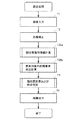
図1の画像照合装置1において、2つの指紋画像を照合するために、画像入力部101から入力した2つの指紋画像に対応の画像(画像データ)Aと画像(画像データ)Bを照合する手順について、図4のフローチャートに従い説明する。
In the
初めに制御部108は、画像入力部101へ画像入力開始の信号を送り、その後、画像入力終了信号を受信するまで待機する。画像入力部101は照合を行なう画像Aを入力し、入力した画像Aをバス103を通してメモリ102の所定アドレスへ格納する(ステップT1)。本実施の形態においては、参照用メモリ1021の所定のアドレスへ格納するものとする。画像入力部101は、画像Aの入力が完了した後、制御部108に画像入力終了信号を送る。
First, the
制御部108は、画像入力終了信号を受信すると、再度、画像入力部101へ画像入力開始の信号を送り、その後、画像入力終了信号を受信するまで待機する。画像入力部101は照合を行なう画像Bを入力し、入力した画像Bをバス103を通してメモリ102の所定アドレスへ格納する(ステップT1)。本実施の形態においては、取込画像用メモリ1023の所定のアドレスへ格納するものとする。画像入力部101は画像Bの入力が完了した後、制御部108に画像入力終了信号を送る。
When receiving the image input end signal, the
次に制御部108は画像補正部104に画像補正開始信号を送り、その後、画像補正終了信号を受信するまで待機する。多くの場合、入力画像は画像入力部101の特性や指の皮膚の乾燥度合いや指を押し付ける圧力に対して各画素の濃淡値や全体の濃度分布が変化するので画質が一様ではないから、入力画像データをそのまま照合に用いることは適当でない。画像補正部104は、画像入力時の条件の変動を抑制するように入力画像の画質を補正する(ステップT2)。具体的には、入力画像データに対応の画像全体もしくは画像を分割した小領域ごとに、ヒストグラムの平坦化(「コンピュータ画像処理入門」総研出版P98)や画像の二値化処理(「コンピュータ画像処理入門」総研出版P66−69)などを、メモリ102に格納された即ち、参照用メモリ1021、取込画像用メモリ1023に格納された画像AとBに施す。
Next, the
画像補正部104は画像Aと画像Bに対する画像補正処理の終了後、制御部108に画像補正処理終了信号を送る。
The image correction unit 104 sends an image correction processing end signal to the
以降で、画像補正部104により画像補正処理を施された画像に対して、特徴値計算部1045により部分画像特徴値計算処理(ステップT25a)が行なわれる。その後、要素判定部1047により照合対象外画像要素判定の処理を行ない(ステップT25b)、そして類似度計算部106による類似度の計算と照合判定部107による照合判定が行なわれて(ステップT3)、結果がプリンタ690またはディスプレイ610から出力される(ステップT4)。ステップT25a、T25bおよびT3の処理についての詳細は後述する。
Thereafter, the partial image feature value calculation process (step T25a) is performed by the feature
(部分画像特徴値の算出)
次に、ステップT25aにおける部分画像の特徴値の算出手順について説明する。
(Calculation of partial image feature values)
Next, the procedure for calculating the feature value of the partial image in step T25a will be described.
<3種類の特徴値>
まず、3種類の特徴値を採る場合について説明する。図5は、照合対象の画像Aと画像Bそれぞれについて、その部分画像に対し、水平・垂直方向の画素数の最大値などを記載した図である。ここでは、画像AとBおよび部分画像は、直交するX軸およびY軸で規定される2次元座標空間に対応の矩形状の平面画像と想定する。図5での部分画像は、X軸に従う水平方向およびY軸に従う垂直方向ともに画素数16である16画素×16画素で構成されている。
<Three feature values>
First, a case where three types of feature values are taken will be described. FIG. 5 is a diagram in which the maximum value of the number of pixels in the horizontal and vertical directions is described for each partial image for each of the images A and B to be verified. Here, the images A and B and the partial image are assumed to be rectangular planar images corresponding to the two-dimensional coordinate space defined by the orthogonal X axis and Y axis. The partial image in FIG. 5 is composed of 16 pixels × 16 pixels having 16 pixels in both the horizontal direction according to the X axis and the vertical direction according to the Y axis.
本実施の形態1による部分画像特徴値計算は計算対象部分画像につきその模様に応じた値を部分画像特徴値として算出する。つまり、水平方向の最大連続黒画素数maxhlenと垂直方向の最大連続黒画素数maxvlenとを検出し、検出した水平方向の最大連続黒画素数maxhlen(模様が水平方向に従う模様である傾向(たとえば横縞である傾向)の大きさを示す値)と垂直方向の最大連続黒画素数maxvlen(模様が垂直方向に従う模様である傾向(たとえば縦縞である傾向)の大きさを示す値)とを比較し、比較結果、相対的に大きい方向が水平方向と判定された場合には、水平(横縞)を意味する値“H”を、垂直方向と判定された場合には、垂直(縦縞)を意味する値“V”を、その他と判定された場合には“X”を出力する。 In the partial image feature value calculation according to the first embodiment, a value corresponding to the pattern of a calculation target partial image is calculated as a partial image feature value. That is, the maximum continuous black pixel number maxhlen in the horizontal direction and the maximum continuous black pixel number maxvlen in the vertical direction are detected, and the detected maximum continuous black pixel number maxhlen in the horizontal direction (the tendency that the pattern follows the horizontal direction (for example, horizontal stripes) )) And the maximum number of continuous black pixels maxvlen in the vertical direction (value indicating the tendency of the pattern to follow the vertical direction (for example, the tendency to be vertical stripes)) As a result of comparison, when a relatively large direction is determined to be a horizontal direction, a value “H” indicating horizontal (horizontal stripes) is used. When a vertical direction is determined, a value indicating vertical (vertical stripes) is determined. If it is determined that “V” is other, “X” is output.
図5を参照して、最大連続黒画素数maxhlenは、水平方向に従うn=0〜15の16個の各行について検出された連続する黒(図中の斜線)画素数のうちの、最大の黒画素数を指す。行について検出された連続する黒画素数とは、当該行が有する黒画素が1つ以上連続する部分のうちから検出した連続する最大の黒画素数を指す。また、最大連続黒画素数maxvlenは、垂直方向に従うm=0〜15の16個の各列について検出された連続する黒(図中の斜線)画素数のうちの、最大の黒画素数を指す。列について検出された連続する黒画素数とは、当該列が有する黒画素が1つ以上連続する部分のうちから検出した連続する最大の黒画素数を指す。 Referring to FIG. 5, the maximum number of continuous black pixels maxhlen is the maximum black among the numbers of continuous black (hatched lines in the figure) detected for each of 16 rows of n = 0 to 15 in the horizontal direction. Refers to the number of pixels. The number of continuous black pixels detected for a row refers to the maximum number of continuous black pixels detected from a portion where one or more black pixels included in the row are continuous. The maximum number of continuous black pixels maxvlen indicates the maximum number of black pixels among the number of continuous black (hatched lines in the figure) detected for each of 16 columns of m = 0 to 15 in the vertical direction. . The number of continuous black pixels detected for a column refers to the maximum number of continuous black pixels detected from a portion where one or more black pixels included in the column are continuous.
但し、上記で“H”あるいは“V”と判定された場合でも、最大連続黒画素数maxhlenおよびmaxvlenのそれぞれが、あらかじめ各方向に対して設定している下限値hlen0およびvlen0の値以上を指していないと判定される場合には、“X”を出力する。これら条件を式として表現すると、maxhlen>maxvlenかつmaxhlen≧hlen0ならば“H”を出力し、maxvlen>maxhlenかつmaxvlen≧vlen0ならば“V”を出力し、その他ならば“X”を出力するとなる。 However, even if it is determined as “H” or “V” in the above, the maximum continuous black pixel numbers maxhlen and maxvlen respectively indicate the lower limit values hlen0 and vlen0 set in advance for each direction. If it is determined that it is not, “X” is output. If these conditions are expressed as an expression, “H” is output if maxhlen> maxvlen and maxhlen ≧ hlen0, “V” is output if maxvlen> maxhlen and maxvlen ≧ vlen0, and “X” is output otherwise. .
図6には、本発明の実施の形態1による部分画像特徴値計算処理のフローチャートが示される。このフローチャートは計算対象となる参照用メモリ1021の参照画像のN個の部分領域の画像である部分画像Riについてそれぞれ繰返されて、計算結果値は各部分画像Ri毎に対応付けて参照用部分画像特徴値計算結果メモリ1024に格納される。同様に取込み画像用メモリ1024の取込画像Bのn個の部分画像Riについてそれぞれ繰返されて、計算結果値は各部分画像Ri毎に対応付けて取込画像用部分画像特徴値計算結果メモリ1025に格納される。
FIG. 6 shows a flowchart of the partial image feature value calculation process according to the first embodiment of the present invention. This flowchart is repeated for each partial image Ri, which is an image of N partial areas of the reference image in the
まず、制御部108は、特徴値計算部1045に部分画像特徴値計算開始信号を送り、その後、部分画像特徴値計算終了信号を受信するまで待機する。特徴値計算部1045は、計算対象画像の部分画像Riを参照用メモリ1021ないしは取込画像用メモリ1023から読出し、計算用メモリ1022に一旦格納する(ステップS1)。特徴値計算部1045は格納された部分画像Riを読出し、水平方向の最大連続黒画素数maxhlenと垂直方向の最大連続黒画素数maxvlenとを求める(ステップS2)。ここで、水平方向の最大連続黒画素数maxhlenと垂直方向の最大連続黒画素数maxvlenとを求める処理を、図7と図8に基づいて説明する。
First, the
図7は、本発明の実施の形態1による部分画像特徴値計算処理(ステップT2a)内の水平方向の最大連続黒画素数maxhlenを求める処理(ステップS2)のフローチャートである。特徴値計算部1045は、計算用メモリ1022から部分画像Riを読出すとともに、水平方向の最大連続黒画素数maxhlenと垂直方向の画素カウンタjとを初期化、即ち、maxhlen=0、j=0とする(ステップSH001)。
FIG. 7 is a flowchart of the process (step S2) for obtaining the maximum horizontal continuous black pixel number maxhlen in the partial image feature value calculation process (step T2a) according to the first embodiment of the present invention. The feature
次に、垂直方向の画素カウンタjの値と垂直方向の最大画素数を指す変数nの値とを比較し(ステップSH002)、j≧nならば、次にステップSH016を実行し、その他ならば、次にステップSH003を実行する。本実施の形態1ではn=16であり、かつ、処理開始時には、j=0であるため、ステップSH003に進む。 Next, the value of the pixel counter j in the vertical direction is compared with the value of the variable n indicating the maximum number of pixels in the vertical direction (step SH002). If j ≧ n, then step SH016 is executed, otherwise Next, step SH003 is executed. In the first embodiment, n = 16, and j = 0 at the start of processing, so the process proceeds to step SH003.
ステップSH003では、水平方向の画素カウンタi、前の画素値c、現在の画素連続数len、現在の行での最大黒画素連続数maxの初期化、即ち、i=0、c=0、len=0、max=0とする(ステップSH003)。次に、水平方向の画素カウンタiと水平方向の最大画素数mとを比較(ステップSH004)し、i≧mならば次にステップSH011を実行し、その他ならば次にステップSH005を実行する。本実施の形態1ではm=16であり、かつ、処理開始時にはi=0であるため、ステップSH005に進む。 In step SH003, initialization of the horizontal pixel counter i, the previous pixel value c, the current pixel continuation number len, and the maximum black pixel continuation number max in the current row, i.e., i = 0, c = 0, len = 0 and max = 0 (step SH003). Next, the horizontal pixel counter i is compared with the horizontal maximum pixel number m (step SH004). If i ≧ m, step SH011 is executed next, and otherwise, step SH005 is executed next. In the first embodiment, since m = 16 and i = 0 at the start of processing, the process proceeds to step SH005.
ステップSH005では、前の画素値cと現在比較対象となっている座標(i,j)の画素値pixel(i,j)とを比較し、c=pixel(i,j)ならばステップSH006を実行し、その他ならばステップSH007を実行する。本実施の形態1では、cは初期化されていて0(白画素)、pixel(0,0)は、図5を参照して、0(白画素)であるため、c=pixel(i,j)が成立すると判定されて(ステップSH005でY)、処理はステップSH006へ進む。 In step SH005, the previous pixel value c is compared with the pixel value pixel (i, j) of the coordinate (i, j) currently being compared. If c = pixel (i, j), step SH006 is executed. Otherwise, execute step SH007. In the first embodiment, since c is initialized and 0 (white pixel) and pixel (0,0) is 0 (white pixel) with reference to FIG. 5, c = pixel (i, When it is determined that j) is satisfied (Y in step SH005), the process proceeds to step SH006.
ステップSH006では、len=len+1を実行する。本実施の形態1では、初期化によりlen=0となっているので、1を付加されて、len=1となる。次に、ステップSH010へ進む。 In step SH006, len = len + 1 is executed. In the first embodiment, len = 0 is set by initialization, so 1 is added and len = 1. Next, the process proceeds to step SH010.
ステップSH010では、i=i+1、即ち、水平方向の画素カウンタiの値を1増加させる。ここでは、初期化によりi=0となっており、1を付加されて、i=1となる。次にステップSH004に戻る。以降、0行目の画素値、即ち、pixel(i,0)は、図5を参照して、すべて白画素で0であるため、i=15となるまで、ステップSH004〜SH010を繰返すこととなり、ステップSH010処理後にi=16となった時点での各々の値は、i=16, c=0, len=15となっている。この状態で次にステップSH004に進む。m=16、i=16であるので、さらにステップSH011に進む。 In step SH010, i = i + 1, that is, the value of the pixel counter i in the horizontal direction is incremented by one. Here, i = 0 is set by initialization, and 1 is added to i = 1. Next, the process returns to step SH004. Thereafter, the pixel values in the 0th row, that is, pixel (i, 0) are all white pixels with reference to FIG. 5, and therefore, steps SH004 to SH010 are repeated until i = 15. The respective values when i = 16 after the processing of step SH010 are i = 16, c = 0, and len = 15. Next, the process proceeds to step SH004 in this state. Since m = 16 and i = 16, the process further proceeds to step SH011.
ステップSH011では、c=1かつmax<lenならばステップSH012を実行し、その他ならばステップSH013を実行する。現時点では、c=0,len=15,max=0であるので、次に、ステップSH013に進む。 In step SH011, if c = 1 and max <len, step SH012 is executed, otherwise, step SH013 is executed. At this time, since c = 0, len = 15, and max = 0, the process proceeds to step SH013.
ステップSH013では、これまでの行での水平方向の最大連続黒画素数maxhlenと現在の行での最大連続黒画素数maxとを比較し、maxhlen<maxならばステップSH014を実行し、その他ならばステップSH015を実行する。現時点では、maxhlen=0,max=0であるので、次に、ステップSH015に進む。 In step SH013, the horizontal maximum continuous black pixel number maxhlen in the previous row is compared with the maximum continuous black pixel number max in the current row. If maxhlen <max, step SH014 is executed, otherwise Step SH015 is executed. Since maxhlen = 0 and max = 0 at the present time, the process proceeds to step SH015.
ステップSH015では、j=j+1、即ち、垂直方向の画素カウンタjの値を1増加させる。現時点では、j=0であるので、j=1となり、SH002に戻ることになる。 In step SH015, j = j + 1, that is, the value of the pixel counter j in the vertical direction is incremented by one. Since j = 0 at the present time, j = 1 and the process returns to SH002.
以降、j=1〜15について同様にステップSH002〜SH015の処理を繰返し、ステップSH015処理後、j=16となった時点で、次にステップSH002で、垂直方向の画素カウンタjの値と垂直方向の最大画素数nの値とを比較する。比較結果、j≧nならば次にステップSH016を実行し、その他ならば次にステップSH003を実行すると、現時点では、j=16、n=16であるので、次に、ステップSH016に進む。 Thereafter, the processing of steps SH002 to SH015 is repeated in the same manner for j = 1 to 15, and when j = 16 after the processing of step SH015, the value of the vertical pixel counter j and the vertical direction are then reached in step SH002. Is compared with the value of the maximum number of pixels n. As a result of the comparison, if j ≧ n, step SH016 is executed next. If not, step SH003 is executed next. Since j = 16 and n = 16 at the present time, the process proceeds to step SH016.
ステップSH016では、maxhlenを出力することになるが、上述の説明、および、図5を参照して、maxhlenには、水平方向の最大連続黒画素数である、y=2行目のmax値の15が格納されていることが分かり、maxhlen=15が出力される。 In step SH016, maxhlen is output. With reference to the above description and FIG. 5, maxhlen is the maximum number of continuous black pixels in the horizontal direction. 15 is stored, and maxhlen = 15 is output.
次に、図8の、本発明の実施の形態1による部分画像特徴値計算処理(ステップT2a)内の垂直方向の最大連続黒画素数maxvlenを求める処理(ステップS2)のフローチャートについて説明するが、図8のステップSV001〜SV016の処理は、上記に説明した図7のフローチャートと基本的に同じ処理を行なうことが明らかであるから、図7の説明から処理内容は容易に理解できる。したがって、図8の詳細な説明は省略する。図8のフローチャートに従う処理が実行される結果、出力される垂直方向の最大連続黒画素数maxvlenは、図5に示されるように、x方向に対するmax値である4を示す。 Next, the flowchart of the process (step S2) for obtaining the maximum continuous black pixel number maxvlen in the vertical direction in the partial image feature value calculation process (step T2a) according to the first embodiment of the present invention will be described. Since it is clear that the processing of steps SV001 to SV016 in FIG. 8 is basically the same as the flowchart in FIG. 7 described above, the processing content can be easily understood from the description in FIG. Therefore, the detailed description of FIG. 8 is omitted. As a result of executing the processing according to the flowchart of FIG. 8, the maximum number of continuous black pixels maxvlen output in the vertical direction indicates 4 which is the maximum value in the x direction, as shown in FIG.
上述の手順で出力されたmaxhlenとmaxvlenとを参照した以降の処理を図6のステップS3以降に戻って説明する。 Processing subsequent to referring to maxhlen and maxvlen output in the above procedure will be described with reference to step S3 and subsequent steps in FIG.
ステップS3では、maxhlenとmaxvlen、および、所定の最大連続黒画素数下限値hlen0とを比較し、maxhlen>maxvlenかつmaxhlen≧hlen0の条件が成立すると判定されるならば(ステップS3でY)、次にステップS7を実行し、成立しないと判定されるならば(ステップS3でN)、次にステップS4を実行する。現時点では、maxhlen=14、maxvlen=4と想定し、さらに下限値hlen0が2と想定すれば、当該条件は成立するので処理はステップS7に進む。ステップS7では、参照用部分画像特徴値計算結果メモリ1024、あるいは、取込画像用部分画像特徴値計算結果メモリ1025の元画像に対する部分画像Riの特徴値格納領域に“H”を格納して、制御部108に部分画像特徴値計算終了信号を送る。
In step S3, maxhlen and maxvlen are compared with a predetermined maximum continuous black pixel number lower limit hlen0, and if it is determined that the conditions of maxhlen> maxvlen and maxhlen ≧ hlen0 are satisfied (Y in step S3), the next Step S7 is executed, and if it is determined that it does not hold (N in Step S3), then Step S4 is executed. At this time, assuming that maxhlen = 14 and maxvlen = 4, and further assuming that the lower limit value hlen0 is 2, the condition is satisfied, and the process proceeds to step S7. In step S7, “H” is stored in the feature value storage area of the partial image Ri for the original image in the reference partial image feature value
仮に、下限値hlen0を15と想定すれば、ステップS3の条件は成立しないと判定されるので、処理は次にステップS4に進む。ステップS4では、maxvlen>maxhlenかつmaxvlen≧vlen0の条件が成立するか否かが判定される。成立すると判定されるならば(ステップS4でY)、次にステップS5の処理が実行されて、成立しないと判定されるならば次にステップS6の処理を実行する。 If the lower limit value hlen0 is assumed to be 15, it is determined that the condition of step S3 is not satisfied, and the process then proceeds to step S4. In step S4, it is determined whether or not the conditions of maxvlen> maxhlen and maxvlen ≧ vlen0 are satisfied. If it is determined that the condition is established (Y in step S4), the process of step S5 is executed next. If it is determined that the condition is not established, the process of step S6 is executed next.
この場合、maxhlen=15、maxvlen=4、およびvlen0=5と想定すれば、当該条件は成立しないので次にステップS6に進む。ステップS6では、参照用部分画像特徴値計算結果メモリ1024、あるいは、取込画像用部分画像特徴値計算結果メモリ1025の元画像に対する部分画像Riの特徴値格納領域に“X”を格納して、制御部108に部分画像特徴値計算終了信号を送る。
In this case, assuming that maxhlen = 15, maxvlen = 4, and vlen0 = 5, the condition is not satisfied, and the process proceeds to step S6. In step S6, “X” is stored in the feature value storage area of the partial image Ri for the original image in the reference partial image feature value
仮にステップS2の出力値がmaxhlen=4およびmaxvlen=10であり、hlen0=2およびvlen0=12であると想定すると、ステップS3の条件は成立せず、さらには、ステップS4の条件も成立しないので、ステップS5の処理が実行される。ステップS5では、参照用部分画像特徴値計算結果メモリ1024、あるいは、取込画像用部分画像特徴値計算結果メモリ1025の元画像に対する部分画像Riの特徴値格納領域に“V”を格納し、制御部108に部分画像特徴値計算終了信号を送る。
Assuming that the output values of step S2 are maxhlen = 4 and maxvlen = 10 and hlen0 = 2 and vlen0 = 12, the condition of step S3 is not satisfied, and further, the condition of step S4 is not satisfied. The process of step S5 is executed. In step S5, “V” is stored in the feature value storage area of the partial image Ri for the original image in the reference partial image feature value
以上のように本実施の形態1による特徴値計算部1045は、計算対象画像の部分画像Ri(図5参照)について、水平方向および垂直方向を各画素列を抽出(特定)して、抽出された画素列それぞれにおける黒画素の個数に基づいて、該部分画像の模様が水平方向に従う模様である傾向(たとえば横縞である傾向)、または垂直方向に従う模様である傾向(たとえば縦縞である傾向)またはそのどちらでもないことを判別して、その判別結果に応じた値(“H”、“V”および“X”のいずれか)を出力する。この出力値が該部分画像Riの特徴値を示す。ここでは連続黒画素の個数に基づき特徴値を求めているが、連続白画素の個数に基づいても同様にして特徴値を求めることができる。
As described above, the feature
<3種類の特徴値の他の例>
次に、3種類の部分画像特徴値の他の例を説明する。そのための部分画像特徴値計算の概略を図9(A)〜(F)に従って説明する。図9(A)〜(F)は、画像の部分画像Riに対し、黒画素(図中の斜線部)と白画素(図中の白地部)の総数などを記載して示す図である。これらの図での部分画像Riは、水平方向、垂直方向ともに画素数16である16画素×16画素の部分領域で構成されている。図9(A)〜(F)では、各部分画像は直交するi軸とj軸で規定される2次元座標空間に対応する平面画像を指す。
<Other examples of three types of feature values>
Next, another example of the three types of partial image feature values will be described. An outline of the partial image feature value calculation for this purpose will be described with reference to FIGS. 9A to 9F are diagrams showing the total number of black pixels (shaded portions in the drawing) and white pixels (white background portion in the drawing) with respect to the partial image Ri of the image. The partial image Ri in these drawings is composed of a partial region of 16 pixels × 16 pixels having 16 pixels in both the horizontal direction and the vertical direction. 9A to 9F, each partial image indicates a planar image corresponding to a two-dimensional coordinate space defined by the orthogonal i-axis and j-axis.
ここでは、図9(A)の計算対象部分画像Riにつき、図9(B)のように計算対象部分画像を左右に1画素ずつずらして重ねたときの黒画素数の増加量hcntと、図9(C)のように計算対象部分画像を上下に1画素ずつずらして重ねたときの黒画素数の増加量vcntとを求め、求めた増加量hcntと増加量vcntとを比較し、増加量hcntが増加量vcntの2倍より大きければ、水平を意味する値“H”を、増加量hcntが増加量vcntの2倍よりも大きければ、垂直を意味する値“V”を出力する。図9(D)〜(F)には他の例が同様に示されている。 Here, for the calculation target partial image Ri in FIG. 9A, the increase amount hcnt of the number of black pixels when the calculation target partial images are shifted one pixel to the left and right as shown in FIG. The amount of increase vcnt of the number of black pixels when the calculation target partial images are shifted one pixel up and down as in 9 (C) is obtained, and the obtained amount of increase hcnt is compared with the amount of increase vcnt. If hcnt is larger than twice the increase amount vcnt, a value “H” meaning horizontal is output, and if the increase amount hcnt is larger than twice the increase amount vcnt, a value “V” meaning vertical is output. Other examples are similarly shown in FIGS. 9D to 9F.
ここでは、図9(A)〜(C)に示す‘画像を左右に1画素ずつずらして重ねたときの黒画素の増加量’とは、『元の画像(16×16画素)の各画素の座標を(i,j)とするならば、全ての画素について座標(i,j)を(i+1,j)となるように元の画像をi軸に平行に+1画素移動させた画像と、全ての画素について座標(i,j)を(i-1,j)となるように元の画像をi軸に平行に-1画素移動させた画像とを生成して、生成した2つの画像と元の画像とを同じ座標(i,j)の画素同士が一致するように重ね合わせて得られる画像(16×16画素)の黒画素の総数と、元の画像の黒画素の総数との差分』を指す。 Here, the “increase amount of black pixels when the image is shifted one pixel to the left and right and overlapped” shown in FIGS. 9A to 9C is “each pixel of the original image (16 × 16 pixels)”. If the coordinates of (i, j) are (i, j), the original image is moved by +1 pixel parallel to the i-axis so that the coordinates (i, j) are (i + 1, j) for all pixels. And an image obtained by moving the original image by −1 pixel parallel to the i axis so that the coordinates (i, j) are (i−1, j) for all the pixels. The total number of black pixels of the image (16 × 16 pixels) obtained by superimposing the image and the original image so that the pixels with the same coordinates (i, j) match, and the total number of black pixels of the original image Point of difference ”.
ここでは、図9(D)〜(F)に示す‘画像を上下に1画素ずつずらして重ねたときの黒画素の増加量’とは、『元の画像(16×16画素)の各画素の座標を(i,j)とするならば、全ての画素について座標(i,j)を(i,j+1)となるように元の画像をj軸に平行に+1画素移動させた画像と、全ての画素について座標(i,j)を(i,j-1)となるように元の画像をj軸に平行に-1画素移動させた画像とを生成して、生成した2つの画像と元の画像とを同じ座標(i,j)の画素同士が一致するように重ね合わせて得られる画像(16×16画素)の黒画素の総数と、元の画像の黒画素の総数との差分』を指す。 Here, the “increase amount of black pixels when the image is shifted one pixel up and down and overlapped” shown in FIGS. 9D to 9F is “each pixel of the original image (16 × 16 pixels)”. If the coordinates of (i, j) are (i, j), the original image is moved +1 pixel parallel to the j-axis so that the coordinates (i, j) are (i, j + 1) for all pixels And an image obtained by moving the original image by −1 pixel parallel to the j axis so that the coordinates (i, j) become (i, j−1) for all the pixels. The total number of black pixels of the image (16 × 16 pixels) obtained by superimposing the image and the original image so that the pixels with the same coordinates (i, j) match, and the total number of black pixels of the original image Point of difference ”.
これらの場合において、ある画素において黒画素どうしが重なると、当該ある画素は黒画素となり、また、白画素と黒画素どうしが重なると当該ある画素は黒画素となり、また、ある画素において白画素どうしが重なると、当該ある画素は白画素となる。 In these cases, when a black pixel overlaps in a certain pixel, the certain pixel becomes a black pixel, and when a white pixel and a black pixel overlap each other, the certain pixel becomes a black pixel. When these overlap, the certain pixel becomes a white pixel.
次に、この部分画像特徴値計算処理の詳細を図10(A)のフローチャートに従って説明する。このフローチャートは計算対象となる参照用メモリ1021の参照画像AのN個の部分画像Riについてそれぞれ繰返されて、計算結果値は各部分画像Ri毎に対応付けて参照用部分画像特徴値計算結果メモリ1024に格納される。同様に取込画像用メモリ1024の取込画像BのN個の部分画像Riについてそれぞれ繰返されて、計算結果値は各部分画像Ri毎に対応付けて取込画像用部分画像特徴値計算結果メモリ1025に格納される。
Next, details of the partial image feature value calculation processing will be described with reference to the flowchart of FIG. This flowchart is repeated for each of the N partial images Ri of the reference image A in the
まず、制御部108は、特徴値計算部1045に部分画像特徴値計算開始信号を送り、その後、部分画像特徴値計算終了信号を受信するまで待機する。
First, the
特徴値計算部1045は、計算対象画像の部分画像Ri(図9(A)参照)を参照用メモリ1021ないしは取込画像用メモリ1023から読出し、計算用メモリ1022に一旦格納する(ステップST1)。部分画像特徴値計算部1045は格納された部分画像Riを読出し、図9(B)のように左右にずらしたときの増加量hcntと図9(C)のように上下にずらしたときの増加量vcntとを求める(ステップST2)。
The feature
増加量hcntと増加量vcntとを求める処理を、図11と図12に基づき説明する。図11は増加量hcntを求める処理(ステップST2)のフローチャートである。図12は増加量vcntを求める処理(ステップST2)のフローチャートである。 Processing for obtaining the increase amount hcnt and the increase amount vcnt will be described with reference to FIGS. 11 and 12. FIG. 11 is a flowchart of a process (step ST2) for obtaining the increase amount hcnt. FIG. 12 is a flowchart of the process for obtaining the increase amount vcnt (step ST2).
図11を参照して、特徴値計算部1045は、計算用メモリ1022から部分画像Riを読出すとともに、垂直方向の画素カウンタjを初期化、すなわち、j=0とする(ステップSHT01)。次に、垂直方向の画素カウンタjと垂直方向の最大画素数nとを比較(ステップSHT02)し、j>nならば次にステップSHT10を実行、その他ならば次にステップSHT03を実行する。ここではn=16であり、かつ、処理開始時には、j=0であるためステップSHT03に進む。
Referring to FIG. 11, feature
ステップSHT03では、水平方向の画素カウンタiの初期化、すなわち、i=0とする。次に、水平方向の画素カウンタiの値と水平方向の最大画素数mとを比較(ステップSHT04)し、i>mならば次にステップSHT05を実行し、その他ならば次にステップSHT06を実行する。ここでは、m=16であり、かつ、処理開始時には、i=0であるため、ステップSHT06に進む。 In step SHT03, the horizontal pixel counter i is initialized, i.e., i = 0. Next, the value of the pixel counter i in the horizontal direction is compared with the maximum number of pixels m in the horizontal direction (step SHT04). If i> m, next step SHT05 is executed, otherwise, step SHT06 is executed next. To do. Here, since m = 16 and i = 0 at the start of processing, the process proceeds to step SHT06.
ステップSHT06では、部分画像Riを読出して現在比較対象となっている座標(i、j)の画素値pixel(i、j)が1(黒画素)であるか、あるいは、座標(i、j)よりも水平方向に一つ左の座標(i-1、j)の画素値pixel(i-1、j)が1であるか、あるいは、座標(i、j)よりも水平方向に一つ右の座標(i+1、j)の画素値pixel(i+1、j)が1であるかを判別する。pixel(i、j)=1あるいはpixel(i-1、j)=1あるいはpixel(i+1、j)=1ならば、次にステップSHT08を実行し、その他ならば次にステップSHT07を実行する。 In step SHT06, the partial image Ri is read and the pixel value pixel (i, j) of the coordinate (i, j) currently being compared is 1 (black pixel) or the coordinate (i, j) The pixel value pixel (i-1, j) of the left coordinate (i-1, j) in the horizontal direction is 1 or the right one in the horizontal direction from the coordinate (i, j) It is determined whether or not the pixel value pixel (i + 1, j) of the coordinates (i + 1, j) is 1. If pixel (i, j) = 1 or pixel (i-1, j) = 1 or pixel (i + 1, j) = 1, then execute step SHT08, otherwise execute next step SHT07 To do.
ここで、部分画像Riの上下左右の1画素分の範囲、すなわち、Ri(-1〜m+1、-1)、Ri(-1、-1〜n+1)、Ri(m+1、-1〜n+1)、Ri(-1〜m+1、n+1)の範囲の画素値は、図10(B)に示すように0(白画素)とする。ここでは、図9(A)を参照して、pixel(0、0)=0、pixel(-1、0)=0、pixel(1、0)=0であるため、ステップSHT07へ進む。 Here, the range of one pixel in the upper, lower, left, and right sides of the partial image Ri, that is, Ri (-1 to m + 1, -1), Ri (-1, -1 to n + 1), Ri (m + 1, The pixel values in the range of −1 to n + 1) and Ri (−1 to m + 1, n + 1) are set to 0 (white pixel) as shown in FIG. Here, referring to FIG. 9A, since pixel (0,0) = 0, pixel (-1,0) = 0, and pixel (1,0) = 0, the process proceeds to step SHT07.
ステップSHT07では、計算用メモリ1022に格納する左右に1画素ずつずらして重ねた画像WHiの座標(i、j)の画素値work(i、j)(図10(C)参照)に0を格納する。すなわち、work(0、0)=0とする。次に、ステップSHT09に進む。
In step SHT07, 0 is stored in the pixel value work (i, j) (see FIG. 10C) of the coordinates (i, j) of the image WHi that is stored in the
ステップSHT09では、i=i+1、すなわち、水平方向の画素カウンタiを1増加させる。ここでは、初期化によりi=0となっており、1を付加されてi=1となる。次にステップSHT04に戻る。以降、0行目の画素値、すなわち、pixel(i、0)は、図9(A)を参照して、すべて白画素で0であるため、i=15となるまで、ステップSHT04〜SHT09を繰返すこととなり、ステップSHT09処理後にi=16となる。この状態でSHT04に進む。m=16、i=16であるのでステップSHT05に進む。 In step SHT09, i = i + 1, that is, the horizontal pixel counter i is incremented by one. Here, i = 0 is obtained by initialization, and 1 is added to i = 1. Next, the process returns to step SHT04. Thereafter, since the pixel values of the 0th row, that is, pixel (i, 0) are all white pixels with reference to FIG. 9A, steps SHT04 to SHT09 are performed until i = 15. Repeatedly, i = 16 after the processing of step SHT09. In this state, the process proceeds to SHT04. Since m = 16 and i = 16, the process proceeds to step SHT05.
ステップSHT05では、j=j+1、すなわち、垂直方向の画素カウンタjを1増加させる
。現時点では、j=0であるので、j=1となり、SHT02に戻ることになる。ここで、新しい行の始まりであるので、0行目と同様に、ステップSHT03、ステップSHT04と進む。以降、pixel(i+1、j)=1となる1行目の14列目の画素、すなわち、i=14、j=1になるまでステップSHT04〜SHT09を繰返すこととなる。ステップSHT09処理後にi=14となる。m=16、i=14であるのでSHT06に進む。
In step SHT05, j = j + 1, that is, the pixel counter j in the vertical direction is incremented by one. At this time, since j = 0, j = 1 and the process returns to SHT02. Here, since it is the start of a new line, the process proceeds to step SHT03 and step SHT04 as in the case of the 0th line. Thereafter, steps SHT04 to SHT09 are repeated until the pixel in the 14th column of the first row where pixel (i + 1, j) = 1, that is, i = 14, j = 1. After step SHT09, i = 14. Since m = 16 and i = 14, the process proceeds to SHT06.
ステップSHT06では、pixel(i+1、j)=1、すなわち、pixel(14+1、1)=1であるので、ステップSHT08に進む。 In step SHT06, since pixel (i + 1, j) = 1, that is, pixel (14 + 1,1) = 1, the process proceeds to step SHT08.
ステップSHT08では、計算用メモリ1022に格納する左右に1画素ずつずらして重ねた画像WHi(図9(B)参照)の座標(i、j)の画素値work(i、j)に1を格納する。すなわち、work(14、1)=1とする。
In step SHT08, 1 is stored in the pixel value work (i, j) of the coordinates (i, j) of the image WHi (see FIG. 9B) which is stored in the
ステップSHT09に進み、i=16となって、ステップSHT04へ進んだ場合、m=16、i=16であるので、ステップSHT05に進み、j=2となって、ステップSHT02へ進む。以降、j=2〜15について同様にステップSHT02〜SHT09の処理を繰返し、ステップSHT09の処理後、j=16となった時点で、次にステップSHT02で、垂直方向の画素カウンタjの値と垂直方向の最大画素数nとを比較し、j≧nならば次にステップSHT10を実行、その他ならば次にステップSHT03を実行する。現時点ではj=16、n=16であるので、次にステップSHT10に進む。この時点で計算用メモリ1022には、現在比較対照を行っている部分画像Riを元に、図9(B)に示すような左右に1画素ずつずらして重ねた画像WHiが格納されている。
When the process proceeds to step SHT09, i = 16 and the process proceeds to step SHT04, m = 16 and i = 16, so the process proceeds to step SHT05, j = 2, and the process proceeds to step SHT02. Thereafter, the processing of steps SHT02 to SHT09 is repeated in the same manner for j = 2 to 15. When j = 16 is obtained after the processing of step SHT09, the vertical value of the pixel counter j in the vertical direction is next vertical in step SHT02. The maximum number of pixels n in the direction is compared. If j ≧ n, next step SHT10 is executed, and otherwise, step SHT03 is executed next. Since j = 16 and n = 16 at the present time, the process proceeds to step SHT10. At this time, the
ステップSHT10では、計算用メモリ1022に格納した左右に1画素ずつずらして重ねた画像WHiの画素値work(i、j)と現在比較対照を行っている部分画像Riの画素値pixel(i、j)の差分cntを計算する。このworkとpixelの差分cntを計算する処理を図13に基づいて説明する。
In step SHT10, the pixel value work (i, j) of the image WHi, which is stored in the
図13は、現在比較対照を行っている部分画像Riの画素値pixel (i、j)と、部分画像Riを左右、あるいは上下に1画素づつずらして重ねた画像WHiの画素値work(i、j)との差分cntを計算するフローチャートである。特徴値計算部1045は、計算用メモリ1022から部分画像Riと1画素づつずらして重ねた画像WHiを読出すとともに、差分カウンタcntと垂直方向の画素カウンタjとを初期化、すなわちcnt=0、j=0とする(ステップSC001)。次に、垂直方向の画素カウンタjの値と垂直方向の最大画素数nとを比較し(ステップSC002)、j≧nならば次に図11のフローチャートに戻り、ステップSHT11でhcntにcntを代入し、その他ならば次にステップSC003を実行する。
FIG. 13 shows the pixel value pixel (i, j) of the partial image Ri currently being compared and the pixel value work (i, j) of the image WHi obtained by shifting the partial image Ri one pixel at a time from left to right or up and down. It is a flowchart which calculates difference cnt with j). The feature
ここでは、n=16であり、かつ、処理開始時には、j=0であるためステップSC003に進む。ステップSC003では、水平方向の画素カウンタiの初期化、すなわち、i=0とする。次に、水平方向の画素カウンタiの値と水平方向の最大画素数mとを比較し(ステップSC004)、i≧mならば次にステップSC005を実行し、その他ならば次にステップSC006を実行する。ここではm=16であり、かつ、処理開始時には、i=0であるため、ステップSC006に進む。 Here, since n = 16 and j = 0 at the start of processing, the process proceeds to step SC003. In step SC003, the horizontal pixel counter i is initialized, i.e., i = 0. Next, the value of the pixel counter i in the horizontal direction is compared with the maximum number of pixels m in the horizontal direction (step SC004). If i ≧ m, next step SC005 is executed, otherwise, step SC006 is executed next. To do. Here, since m = 16 and i = 0 at the start of processing, the process proceeds to step SC006.
ステップSC006では、現在比較対象となっている座標(i、j)の部分画像Riの画素値pixel(i、j)が0(白画素)であり、かつ、1画素づつずらして重ねた画像WHiの画素値work(i、j)が1(黒画素)であるかを判別し、pixel(i、j)=0かつwork(i、j)=1ならば次にステップSC007を実行し、その他ならば次にステップSC008を実行する。ここでは、図9(A)と図9(B)を参照して、pixel(0、0)=0、work(0、0)=0であるため、ステップSC008へ進む。 In step SC006, the pixel value pixel (i, j) of the partial image Ri of the coordinates (i, j) that is currently the comparison target is 0 (white pixel), and the image WHi is overlaid by shifting one pixel at a time. Whether pixel value work (i, j) is 1 (black pixel), and if pixel (i, j) = 0 and work (i, j) = 1, then step SC007 is executed and the others Then, step SC008 is executed. Here, referring to FIG. 9A and FIG. 9B, pixel (0,0) = 0 and work (0,0) = 0, so the process proceeds to step SC008.
ステップSC008では、i=i+1、すなわち、水平方向の画素カウンタiを1増加させる。ここでは、初期化によりi=0となっており、1を加えてi=1となる。次にステップSC004に戻る。以降、0行目の画素値、すなわちpixel(i、0)とwork(i、0)は、図9(A)と図9(B)を参照して、すべて白画素で0であるため、i=15となるまで、ステップSC004〜SC008を繰返すこととなり、ステップSC008処理後にi=16となった時点での各々の値は、cnt=0、i=16となっている。この状態でSC004に進む。m=16、i=16であるので、ステップSC005に進む。 In step SC008, i = i + 1, that is, the horizontal pixel counter i is incremented by one. Here, i = 0 is set by initialization, and 1 is added by adding 1. Next, the process returns to step SC004. Thereafter, since the pixel values of the 0th row, that is, pixel (i, 0) and work (i, 0) are all white pixels with reference to FIG. 9 (A) and FIG. 9 (B), Steps SC004 to SC008 are repeated until i = 15, and the respective values when i = 16 after the processing of step SC008 are cnt = 0 and i = 16. In this state, the process proceeds to SC004. Since m = 16 and i = 16, the process proceeds to step SC005.
ステップSC005ではj=j+1、すなわち、垂直方向の画素カウンタjを1増加させる。現時点では、j=0であるので、j=1となり、SC002に戻ることになる。ここで、新しい行の始まりであるので、0行目と同様に、ステップSC003、ステップSC004と進む。以降、pixel(i、j)=0、かつ、work(i、j)=1となる1行目の14列目の画素、すなわち、i=15、j=1になるまでステップSC004〜SC008を繰返すこととなり、ステップSC008処理後にi=15となる。m=16、i=15であるのでSC006に進む。 In step SC005, j = j + 1, that is, the vertical pixel counter j is incremented by one. At this time, since j = 0, j = 1 and the process returns to SC002. Here, since it is the start of a new line, the process proceeds to step SC003 and step SC004 as in the 0th line. Thereafter, the pixels in the 14th column of the first row where pixel (i, j) = 0 and work (i, j) = 1, that is, steps SC004 to SC008 are performed until i = 15 and j = 1. Repeatedly, i = 15 after the process of step SC008. Since m = 16 and i = 15, the process proceeds to SC006.
ステップSC006では、pixel(i、j)=0かつwork(i、j)=1、すなわち、pixel(14、1)=0かつwork(14、1)=1であるので、ステップSC007に進む。 In step SC006, since pixel (i, j) = 0 and work (i, j) = 1, that is, pixel (14, 1) = 0 and work (14, 1) = 1, the process proceeds to step SC007.
ステップSC007では、cnt=cnt+1、すなわち差分カウンタcntの値を1増加させる。ここでは、初期化によりcnt=0となっており、1を加えてcnt=1となる。次に、ステップSC008に進み、i=16となってステップSC004へ進む。m=16、i=16であるので、ステップSC005に進み、j=2となってステップSC002へ進む。 In step SC007, cnt = cnt + 1, that is, the value of the difference counter cnt is incremented by one. Here, cnt = 0 is set by initialization, and 1 is added to set cnt = 1. Next, the process proceeds to step SC008, i = 16, and the process proceeds to step SC004. Since m = 16 and i = 16, the process proceeds to step SC005, j = 2, and the process proceeds to step SC002.
以降、j=2〜15について同様にステップSC002〜SC009の処理を繰返し、ステップSC008処理後、j=15となった時点で、次にステップSC002で、垂直方向の画素カウンタjの値と垂直方向の最大画素数nとを比較し、j≧nならば次に図11のフローチャートに戻り、ステップSHT11を実行し、その他ならば次にステップSC003を実行する。現時点では、j=16、n=16であるので、図12のフローチャートを終了し、次に図11のフローチャートに戻り、ステップSHT11に進む。現時点では、差分カウンタcnt=21となっている。 Thereafter, the processing of steps SC002 to SC009 is repeated in the same manner for j = 2 to 15. When j = 15 after the processing of step SC008, the value of the vertical pixel counter j and the vertical direction are next determined in step SC002. The maximum number of pixels n is compared. If j ≧ n, the process returns to the flowchart of FIG. 11 to execute step SHT11. Otherwise, step SC003 is executed. At this time, since j = 16 and n = 16, the flowchart of FIG. 12 is terminated, and then the process returns to the flowchart of FIG. 11 and proceeds to step SHT11. At present, the difference counter cnt = 21.
ステップSHT11では、hcnt=cnt、すなわち左右にずらしたときの増加量hcntに図12のフローチャートで計算した差分cntの値を代入する。次にステップSHT12に進む。ステップSHT12では、左右にずらしたときの増加量hcnt=21を出力する。 In step SHT11, hcnt = cnt, that is, the value of the difference cnt calculated in the flowchart of FIG. Next, the process proceeds to step SHT12. In step SHT12, an increase amount hcnt = 21 when shifted left and right is output.
次に、図10の特徴値計算処理(ステップT2a)内の上下にずらしたときの増加量vcntを求める処理(ステップST2)の図12のステップSVT01〜SVT12の処理は、上記に説明した図11と基本的に同じ処理を行なうことが明らかであり、詳細な説明は省略する。 Next, the processing of steps SVT01 to SVT12 of FIG. 12 of the processing (step ST2) for obtaining the increase amount vcnt when shifted up and down in the feature value calculation processing (step T2a) of FIG. 10 is described above with reference to FIG. It is clear that basically the same processing is performed, and detailed description is omitted.
出力される上下にずらしたときの増加量vcntとして、図9(C)の上下に1画素づつずらして重ねた画像WViと図9(A)の部分画像Riとの差分である96が出力される。 As the amount of increase vcnt when shifted up and down, 96 is output which is the difference between the image WVi and the partial image Ri of FIG. The
出力されたhcntとvcntとについて以降の処理を図10のステップST3以降に戻って説明する。 The subsequent processing for the output hcnt and vcnt will be described by returning to step ST3 and subsequent steps in FIG.
ステップST3では、hcntとvcnt、および、上下方向の最大黒画素数増加量下限値vcnt0とを比較し、vcnt>2×hcntかつvcnt≧vcnt0の条件が成立するならば次にステップST7を実行し、成立しないならば次にステップST4を実行する。現時点では、vcnt=96、hcnt=21であり、vcnt0=4と想定すれば、処理は次にステップST7に進む。ステップST7では、参照用部分画像特徴値計算結果メモリ1024、あるいは、取込画像用部分画像特徴値計算結果メモリ1025の元の画像に対する部分画像Riの特徴値格納領域に“H”を格納して、制御部108に部分画像特徴値計算終了信号を送る。
In step ST3, hcnt and vcnt are compared with the maximum black pixel number increase lower limit value vcnt0 in the vertical direction. If the condition of vcnt> 2 × hcnt and vcnt ≧ vcnt0 is satisfied, then step ST7 is executed. If not, step ST4 is executed next. At this time, assuming that vcnt = 96, hcnt = 21, and vcnt0 = 4, the process proceeds to step ST7. In step ST7, “H” is stored in the feature value storage area of the partial image Ri for the original image in the reference partial image feature value
仮に、ステップST2の出力値が、vcnt=30、hcnt=20であり、vcnt0=4と想定するならば、ステップST3の条件は成立しないので次にステップST4に進む。ステップST4では、hcnt>2×vcntかつhcnt≧hcnt0の条件が成立すると判定されるならば次にステップST5を実行し、成立しないと判定されるならば、次にステップST6を実行する。 If it is assumed that the output values of step ST2 are vcnt = 30, hcnt = 20 and vcnt0 = 4, the condition of step ST3 is not satisfied, so the process proceeds to step ST4. In step ST4, if it is determined that the conditions of hcnt> 2 × vcnt and hcnt ≧ hcnt0 are satisfied, step ST5 is executed next. If it is determined that the conditions are not satisfied, step ST6 is then executed.
ここでは次にステップST6に進み、参照用部分画像特徴値計算結果メモリ1024、あるいは、取込画像用部分画像特徴値計算結果メモリ1025の元の画像に対する部分画像Riの特徴値格納領域に“X”を格納し、制御部108に部分画像特徴値計算終了信号を送る。
In step ST6, the reference partial image feature value
さらに、仮にステップST2の出力値が、vcnt=30、hcnt=70であり、hcnt0=4と想定するならば、ステップST3で、vcnt>2×hcntかつvcnt≧vcnt0が成立しないと判定されるので、次にステップST4を実行する。ステップST4では、hcnt>2×vcntかつhcnt≧hcnt0の条件が成立するか否かが判定される。成立すると判定されるならば次にステップST5を実行し、成立しないと判定されるならば次にステップST6を実行する。 Further, assuming that the output values of step ST2 are vcnt = 30, hcnt = 70 and hcnt0 = 4, it is determined in step ST3 that vcnt> 2 × hcnt and vcnt ≧ vcnt0 is not satisfied. Next, step ST4 is executed. In step ST4, it is determined whether or not the conditions of hcnt> 2 × vcnt and hcnt ≧ hcnt0 are satisfied. If it is determined that it is satisfied, next step ST5 is executed, and if it is determined that it is not satisfied, next step ST6 is executed.
ここでは成立すると判定されるので、次にステップST5に進み、参照用部分画像特徴値計算結果メモリ1024、あるいは、取込画像用部分画像特徴値計算結果メモリ1025の元の画像に対する部分画像Riの特徴値格納領域に“V”を格納し、制御部108に部分画像特徴値計算終了信号を送る。
Here, since it is determined to be established, the process proceeds to step ST5, where the partial image Ri of the reference partial image feature value
このようにして算出される部分画像特徴値計算は、参照画像A、あるいは、取込画像Bにノイズがある場合、例えば、指のしわ等によって指紋画像の一部が欠けているために、図9(D)に示すように部分画像Riの中央に垂直にしわが入っているような画像であっても、図9(E)と図9(F)に示すように、hcnt=29とvcnt=90となって、vcnt0=4と設定すれば、図10のステップST3で、vcnt>2×hcntかつvcnt≧vcnt0ならば次にステップST7を実行し、水平を意味する値“H”を出力する。このように部分画像特徴値計算は、画像に含まれるノイズ成分に対して計算精度を維持できるという特徴を持つ。 In the partial image feature value calculation calculated in this way, when there is noise in the reference image A or the captured image B, for example, a part of the fingerprint image is missing due to finger wrinkles or the like. As shown in FIGS. 9E and 9F, even if the image has a vertical wrinkle at the center of the partial image Ri as shown in FIG. 9D, hcnt = 29 and vcnt = If vcnt0 = 4 and vcnt0 = 4 is set, in step ST3 of FIG. 10, if vcnt> 2 × hcnt and vcnt ≧ vcnt0, then step ST7 is executed and a value “H” meaning horizontal is output. . As described above, the partial image feature value calculation has a feature that the calculation accuracy can be maintained for the noise component included in the image.
上述のように特徴値計算部1045は、部分画像Riについて、左右に所定の画素づつずらして重ねた画像WHiと、上下に所定の画素づつずらして重ねた画像WViとを各々求め、さらに、その左右に1画素づつずらして重ねた画像WHiと部分画像Riとの差分である黒画素数の増加量hcntと、上下に1画素づつずらして重ねた画像WViと部分画像Riとの差分である黒画素数の増加量vcntとを各々求め、それら増加量に基づいて、該部分画像Riの模様が水平方向に従う模様である傾向(たとえば横縞である傾向)、または垂直方向に従う模様である傾向(たとえば縦縞である傾向)またはそのどちらでもないことを判別して、その判別結果に応じた値(“H”、“V”および“X”のいずれか)を出力する。この出力値が該部分画像Riの特徴値を示す。
As described above, the feature
<3種類の特徴値の更なる他の例>
部分画像特徴値の3種類は、上述のものに限定されず、次のような別の3種類であってもよい。そのための部分画像特徴値計算の概略を図14(A)〜(F)に従って説明する。図14(A)〜(F)は、画像の部分画像Riに対し、黒画素と白画素の総数などを記載して示す図である。これらの図での部分画像Riは、水平方向、垂直方向ともに画素数16である16画素×16画素の部分領域で構成されている。部分画像特徴値計算は、図14(A)の計算対象部分画像Riにつき、計算対象部分画像を右斜め方向に1画素づつずらして重ねたときの黒画素数の増加量rcnt(すなわち図14(B)の画像WHiの斜線部分)と、計算対象部分画像を左斜め方向に1画素づつずらして重ねたときの黒画素数の増加量lcnt(すなわち図14(C)の画像WViの斜線部分)とを求め、求めた増加量rcntと増加量lcntとを比較し、増加量lcntが増加量rcntの2倍より大きければ、右斜めを意味する値“R”を、増加量rcntが増加量lcntの2倍よりも大きければ、左斜めを意味する値“L”を、その他の場合には“X”を出力する。
<Further another example of three types of feature values>
The three types of partial image feature values are not limited to those described above, and may be the following three types. An outline of partial image feature value calculation for that purpose will be described with reference to FIGS. FIGS. 14A to 14F are diagrams showing the total number of black pixels and white pixels and the like for the partial image Ri of the image. The partial image Ri in these drawings is composed of a partial region of 16 pixels × 16 pixels having 16 pixels in both the horizontal direction and the vertical direction. In the partial image feature value calculation, the increase amount rcnt of the black pixel when the calculation target partial image Ri is shifted by one pixel in the diagonally rightward direction and overlapped with respect to the calculation target partial image Ri in FIG. (B) hatched portion of the image WHi) and the increase amount lcnt of the number of black pixels when the calculation target partial image is shifted by one pixel in the left diagonal direction (that is, the shaded portion of the image WVi in FIG. 14C) And the obtained increase amount rcnt is compared with the increase amount lcnt. If the increase amount lcnt is larger than twice the increase amount rcnt, the value “R” means the diagonally right, and the increase amount rcnt is the increase amount lcnt. If the value is larger than 2 times, a value “L” meaning left oblique is output, and “X” is output in other cases.
‘画像を右斜め方向に1画素ずつずらして重ねたときの黒画素の増加量’とは、『元の画像(16×16画素)の各画素の座標を(i,j)とするならば、全ての画素について座標(i,j)を(i+1,j-1)となるように元の画像を移動させた画像と、全ての画素について座標(i,j)を(i-1,j+1)となるように元の画像を移動させた画像とを生成して、生成した2つの画像と元の画像とを同じ座標(i,j)の画素同士が一致するように重ね合わせて得られる画像(16×16画素)の黒画素の総数と、元の画像の黒画素の総数との差分』を指す。 'The amount of increase in black pixels when the image is shifted one pixel at a time in the diagonally right direction' means "if the coordinates of each pixel in the original image (16 x 16 pixels) are (i, j) The original image is moved so that the coordinates (i, j) are (i + 1, j-1) for all pixels, and the coordinates (i, j) are (i-1) for all pixels. , j + 1), and an image obtained by moving the original image so as to be overlapped, and the generated two images and the original image are overlapped so that the pixels having the same coordinates (i, j) coincide with each other It refers to the difference between the total number of black pixels of the image (16 × 16 pixels) obtained together and the total number of black pixels of the original image ”.
‘画像を左斜め方向に1画素ずつずらして重ねたときの黒画素の増加量’とは、『元の画像(16×16画素)の各画素の座標を(i,j)とするならば、全ての画素について座標(i,j)を(i-1,j-1)となるように元の画像を移動させた画像と、全ての画素について座標(i,j)を(i+1,j-1)となるように元の画像を移動させた画像とを生成して、生成した2つの画像と元の画像とを同じ座標(i,j)の画素同士が一致するように重ね合わせて得られる画像(16×16画素)の黒画素の総数と、元の画像の黒画素の総数との差分』を指す。 'The amount of increase in black pixels when the image is shifted one pixel at a time in the left diagonal direction' means "if the coordinates of each pixel in the original image (16 x 16 pixels) are (i, j) The original image is moved so that the coordinates (i, j) are (i-1, j-1) for all the pixels, and the coordinates (i, j) are (i + 1) for all the pixels. , j-1), and an image obtained by moving the original image so that the two images and the original image are overlapped so that the pixels with the same coordinates (i, j) match. It refers to the difference between the total number of black pixels of the image (16 × 16 pixels) obtained together and the total number of black pixels of the original image ”.
この場合、ある画素において黒画素どうしが重なると、当該ある画素は黒画素となり、また、白画素と黒画素どうしが重なると当該ある画素は黒画素となり、また、ある画素において白画素どうしが重なると、当該ある画素は白画素となる。 In this case, when a black pixel overlaps a certain pixel, the certain pixel becomes a black pixel. When a white pixel and a black pixel overlap each other, the certain pixel becomes a black pixel. Also, a certain pixel overlaps a white pixel. Then, the certain pixel becomes a white pixel.
ただし、上記で“R”あるいは“L”と判定された場合でも、黒画素数の増加量があらかじめ両方向に対して設定している下限値lcnt0ないしrcnt0以上でないならば“X”を出力する。これら条件を式として表現すると、(1)lcnt>2×rcntかつ(2)lcnt≧lcnt0が成立するならば“R”を出力し、(3)rcnt>2×lcntかつ(4)rcnt≧rcnt0が成立するならば“L”を出力し、その他ならば“X”を出力するとなる。 However, even when “R” or “L” is determined as described above, “X” is output if the amount of increase in the number of black pixels is not equal to or lower than the lower limit values lcnt0 to rcnt0 set in advance in both directions. If these conditions are expressed as an expression, “R” is output if (1) lcnt> 2 × rcnt and (2) lcnt ≧ lcnt0 is satisfied, (3) rcnt> 2 × lcnt and (4) rcnt ≧ rcnt0 If the above holds, “L” is output, otherwise “X” is output.
ここでは、増加量lcntが増加量rcntの2倍より大きければ右斜めを意味する値“R”を出力しているが、この閾値を指す2倍という値を別の値に変更しても良い。右斜め方向についても同様である。さらに、部分画像の中で黒画素数がある範囲(例えば部分画像Riの全体画素数に対して30%以上70%以下など)内にあり、照合処理に適する画像であることが予めわかっているような場合は、上記(2)と(4)の条件式については削除しても良い。 Here, if the increase amount lcnt is larger than twice the increase amount rcnt, the value “R” that is diagonally right is output. However, the value that is twice the threshold value may be changed to another value. . The same applies to the right diagonal direction. Further, it is known in advance that the image is suitable for collation processing because it is within a certain range (for example, 30% or more and 70% or less of the total number of pixels of the partial image Ri) in the partial image. In such a case, the conditional expressions (2) and (4) may be deleted.
図15(A)は、さらなる他の部分画像特徴値計算処理のフローチャートである。このフローチャートは計算対象となる参照用メモリ1021の参照画像AのN個の部分画像Riについてそれぞれ繰返されて、計算結果値は各部分画像Ri毎に対応付けて参照用部分画像特徴値計算結果メモリ1024に格納される。同様に取込画像用メモリ1024の取込画像BのN個の部分画像Riについてそれぞれ繰返されて、計算結果値は各部分画像Ri毎に対応付けて取込画像用部分画像特徴値計算結果メモリ1025に格納される。次に、この部分画像特徴値計算処理の詳細を図15に従って説明する。
FIG. 15A is a flowchart of still another partial image feature value calculation process. This flowchart is repeated for each of the N partial images Ri of the reference image A in the
制御部108は、特徴値計算部1045に部分画像特徴値計算開始信号を送り、その後、部分画像特徴値計算終了信号を受信するまで待機する。
The
特徴値計算部1045は、計算対象画像の部分画像Ri(図14(A)参照)を参照用メモリ1021ないしは取込画像用メモリ1023から読出し、計算用メモリ1022に一旦格納する(ステップSM1)。特徴値計算部1045は格納された部分画像Riを読出し、図14(B)のように右斜め方向にずらしたときの増加量rcntと図14(C)のように左斜め方向にずらしたときの増加量lcntとを求める(ステップSM2)。
The feature
増加量rcntと増加量lcntとを求める処理を、図16と図17に基づき説明する。図16は部分画像特徴値計算処理(ステップT2a)内の右斜め方向にずらしたときの増加量rcntを求める処理(ステップSM2)のフローチャートである。 A process for obtaining the increase amount rcnt and the increase amount lcnt will be described with reference to FIGS. FIG. 16 is a flowchart of the process (step SM2) for obtaining the increase amount rcnt when shifted in the diagonally right direction in the partial image feature value calculation process (step T2a).
図16を参照して、特徴値計算部1045は、計算用メモリ1022から部分画像Riを読出すとともに、垂直方向の画素カウンタjの値を初期化、すなわち、j=0とする(ステップSR01)。次に、垂直方向の画素カウンタjの値と垂直方向の最大画素数nとを比較(ステップSR02)し、比較結果がj≧nを指すならば次にステップSR10を実行、指さないならば次にステップSR03を実行する。ここではn=16であり、かつ、処理開始時には、j=0であるためステップSR03に進む。
Referring to FIG. 16, feature
ステップSR03では、水平方向の画素カウンタiの値の初期化、すなわち、i=0とする。次に、水平方向の画素カウンタiの値と水平方向の最大画素数mとを比較(ステップSR04)し、比較結果がi≧mを指すならば次にステップSR05を実行し、指さないならば次にステップSR06を実行する。本実施の形態ではm=16であり、かつ、処理開始時には、i=0であるため、ステップSR06に進む。 In step SR03, the value of the pixel counter i in the horizontal direction is initialized, i.e., i = 0. Next, the value of the pixel counter i in the horizontal direction is compared with the maximum number m of pixels in the horizontal direction (step SR04). If the comparison result indicates i ≧ m, then step SR05 is executed, otherwise it is not indicated. Next, step SR06 is executed. In the present embodiment, m = 16, and i = 0 at the start of processing, so the process proceeds to step SR06.
ステップSR06では、部分画像Riを読出し、現在比較対象となっている座標(i、j)の画素値pixel(i、j)が1(黒画素)であるか、あるいは、座標(i、j)よりも一つ右上の座標(i+1、j+1)の画素値pixel(i+1、j+1)が1であるか、あるいは、座標(i、j)よりも一つ右下の座標(i+1、j-1)の画素値pixel(i+1、j-1)が1であるかを判別する。pixel(i、j)=1あるいはpixel(i+1、j+1)=1あるいはpixel(i+1、j-1)=1であると判別するならば、次にステップSR08を実行し、その他ならば次にステップSR07を実行する。 In step SR06, the partial image Ri is read and the pixel value pixel (i, j) of the coordinate (i, j) currently being compared is 1 (black pixel) or the coordinate (i, j). The pixel value pixel (i + 1, j + 1) of the upper right coordinate (i + 1, j + 1) is 1 or one lower right of the coordinate (i, j) It is determined whether or not the pixel value pixel (i + 1, j-1) at the coordinates (i + 1, j-1) is 1. If it is determined that pixel (i, j) = 1 or pixel (i + 1, j + 1) = 1 or pixel (i + 1, j-1) = 1, then step SR08 is executed, Otherwise, step SR07 is executed next.
ここで、部分画像Riの上下左右の1画素分の範囲、すなわち、Ri(-1〜m+1、-1)、Ri(-1、-1〜n+1)、Ri(m+1、-1〜n+1)、Ri(-1〜m+1、n+1)の範囲の画素値は、図15(B)に示すように0(白画素)とする。ここでは、図14(A)を参照して、pixel(0、0)=0、pixel(1、1)=0、pixel(1、-1)=0であるため、ステップSR07へ進む。 Here, the range of one pixel in the upper, lower, left, and right sides of the partial image Ri, that is, Ri (-1 to m + 1, -1), Ri (-1, -1 to n + 1), Ri (m + 1, The pixel values in the range of −1 to n + 1) and Ri (−1 to m + 1, n + 1) are set to 0 (white pixel) as shown in FIG. Here, referring to FIG. 14A, since pixel (0, 0) = 0, pixel (1, 1) = 0, and pixel (1, −1) = 0, the process proceeds to step SR07.
ステップSR07では、計算用メモリ1022に格納する右斜め方向に1画素づつずらして重ねた画像WHiの座標(i、j)の画素値work(i、j)(図15(C)参照)に0を格納する。すなわち、work(0、0)=0とする。次に、ステップSR09に進む。
In step SR07, the pixel value work (i, j) of the coordinates (i, j) of the image WHi, which is stored in the
ステップSR09では、i=i+1、すなわち、水平方向の画素カウンタiの値を1増加させる。ここでは、初期化によりi=0となっており、1が加えられてi=1となる。次にステップSR04に戻る。 In step SR09, i = i + 1, that is, the value of the pixel counter i in the horizontal direction is incremented by one. Here, i = 0 is set by initialization, and 1 is added to i = 1. Next, the process returns to step SR04.
ステップSR05では、j=j+1、すなわち、垂直方向の画素カウンタjの値を1増加させる。現時点では、j=0であるので、j=1となり、SR02に戻ることになる。ここで、新しい行の始まりであるので、0行目と同様に、ステップSR03、ステップSR04と進む。以降、pixel(i、j)=1となる1行目の5列目の画素、すなわち、i=5、j=1になるまでステップSR04〜SR09を繰返すこととなり、ステップSR09処理後にi=5となる。m=16、i=5であるのでSR06に進む。 In step SR05, j = j + 1, that is, the value of the pixel counter j in the vertical direction is incremented by one. At this time, since j = 0, j = 1 and the process returns to SR02. Here, since it is the start of a new line, the process proceeds to step SR03 and step SR04 as in the case of the 0th line. Thereafter, steps SR04 to SR09 are repeated until the pixel of the first column in the first row where pixel (i, j) = 1, i.e., i = 5, j = 1, and i = 5 after the processing of step SR09. It becomes. Since m = 16 and i = 5, the process proceeds to SR06.
ステップSR06では、pixel(i、j)=1、すなわち、pixel(5、1)=1であるので、ステップSR08に進む。 In step SR06, since pixel (i, j) = 1, that is, pixel (5, 1) = 1, the process proceeds to step SR08.
ステップSR08では、計算用メモリ1022に格納する右斜め方向に1画素づつずらして重ねた画像WRi(図14(B)参照)の座標(i、j)の画素値work(i、j)に1を格納する。すなわち、work(5、1)=1とする。
In step SR08, the pixel value work (i, j) of the coordinates (i, j) of the image WLi (see FIG. 14B) that is stored in the
ステップSR09に進み、i=16となって、ステップSR04へ進む。m=16、i=16であるので、ステップSR05に進み、j=2となって、ステップSR02へ進む。以降、j=2〜15について同様にステップSR02〜SR09の処理を繰返し、ステップSR09の処理後、j=16となった時点で、次にステップSR02で、垂直方向の画素カウンタjの値と垂直方向の最大画素数nとを比較し、比較結果がj≧nを指すならば次にステップSR10を実行、指さないならば次にステップSR03を実行する。現時点ではj=16、n=16であるので、次にステップSR10に進む。この時点で計算用メモリ1022には、現在比較対照を行っている部分画像Riを元に、図14(B)に示すような右斜め方向に1画素づつずらして重ねた画像WRiが格納されている。
Proceeding to step SR09, i = 16, and proceeding to step SR04. Since m = 16 and i = 16, the process proceeds to step SR05, j = 2, and the process proceeds to step SR02. Thereafter, the processing of steps SR02 to SR09 is repeated in the same manner for j = 2 to 15, and after j = 16 after the processing of step SR09, next, in step SR02, the value of the vertical pixel counter j is The maximum number of pixels n in the direction is compared. If the comparison result indicates j ≧ n, step SR10 is executed next. If not, step SR03 is executed next. Since j = 16 and n = 16 at the present time, the process proceeds to step SR10. At this time, the
ステップSR10では、計算用メモリ1022に格納した右斜め方向に1画素づつずらして重ねた画像WRiの画素値work(i、j)と現在比較対照を行っている部分画像Riの画素値pixel(i、j)の差分cntを計算する。このworkとpixelの差分cntを計算する処理を図18に基づいて説明する。
In step SR10, the pixel value work (i, j) of the image WLi that is stored in the
図18は、現在比較対照を行っている部分画像Riの画素値pixel (i、j)と、部分画像Riを右斜め方向、あるいは左斜め方向に1画素づつずらして重ねた画像WRiの画素値work(i、j)との差分cntを計算するフローチャートである。特徴値計算部1045は、計算用メモリ1022から部分画像Riと1画素づつずらして重ねた画像WRiを読出すとともに、差分カウンタcntと垂直方向の画素カウンタjの値を初期化、すなわちcnt=0、j=0とする(ステップSN001)。次に、垂直方向の画素カウンタjの値と垂直方向の最大画素数nとを比較し(ステップSN002)、比較結果がj≧nを指すならば次に図16のフローチャートに戻り、ステップSR11でrcntにcntを代入し、指さないならば次にステップSN003を実行する。
FIG. 18 shows the pixel value pixel (i, j) of the partial image Ri that is currently being compared and the pixel value of the image Wri in which the partial image Ri is shifted one pixel at a time in the right diagonal direction or left diagonal direction. It is a flowchart which calculates difference cnt with work (i, j). The feature
ここではn=16であり、かつ、処理開始時には、j=0であるためステップSN003に進む。ステップSN003では、水平方向の画素カウンタiの初期化、すなわち、i=0とする。次に、水平方向の画素カウンタiの値と水平方向の最大画素数mとを比較し(ステップSN004)、比較結果がi≧mを指すならば次にステップSN005を実行し、指さないならば次にステップSN006を実行する。ここではm=16であり、かつ、処理開始時には、i=0であるため、ステップSN006に進む。 Here, n = 16, and at the start of processing, j = 0, so the process proceeds to step SN003. In step SN003, the horizontal pixel counter i is initialized, i.e., i = 0. Next, the value of the pixel counter i in the horizontal direction is compared with the maximum number of pixels m in the horizontal direction (step SN004). If the comparison result indicates i ≧ m, then step SN005 is executed. Next, step SN006 is executed. Here, since m = 16 and i = 0 at the start of processing, the process proceeds to step SN006.
ステップSN006では、現在比較対象となっている座標(i、j)の部分画像Riの画素値pixel(i、j)が0(白画素)であり、かつ、1画素づつずらして重ねた画像WRiの画素値work(i、j)が1(黒画素)であるかを判別し、pixel(i、j)=0かつwork(i、j)=1ならば次にステップSN007を実行し、その他ならば次にステップSN008を実行する。ここでは、図14(A)と図14(B)を参照して、pixel(0、0)=0、work(0、0)=0であるため、ステップSN008へ進む。 In step SN006, the pixel value pixel (i, j) of the partial image Ri of the coordinates (i, j) currently being compared is 0 (white pixel), and the image WRI is superimposed by shifting by one pixel. Whether pixel value work (i, j) is 1 (black pixel), and if pixel (i, j) = 0 and work (i, j) = 1, then step SN007 is executed and the others Then, step SN008 is executed next. Here, referring to FIG. 14A and FIG. 14B, since pixel (0,0) = 0 and work (0,0) = 0, the process proceeds to step SN008.
ステップSN008では、i=i+1、すなわち、水平方向の画素カウンタiを1増加させる。ここでは、初期化によりi=0となっており、1を加えてi=1となる。次にステップSN004に戻る。以降、i=15となるまで、ステップSN004〜SN008を繰返すこととなり、ステップSN008処理後にi=16となった時点でSN004に進む。m=16、i=16であるので、ステップSN005に進む。 In step SN008, i = i + 1, that is, the horizontal pixel counter i is incremented by one. Here, i = 0 is set by initialization, and 1 is added by adding 1. Next, the process returns to step SN004. Thereafter, steps SN004 to SN008 are repeated until i = 15, and the process proceeds to SN004 when i = 16 after the processing of step SN008. Since m = 16 and i = 16, the process proceeds to step SN005.
ステップSN005ではj=j+1、すなわち、垂直方向の画素カウンタjの値を1増加させる。現時点では、j=0であるので、j=1となり、SN002に戻ることになる。ここで、新しい行の始まりであるので、0行目と同様に、ステップSN003、ステップSN004と進む。以降、pixel(i、j)=0、かつ、work(i、j)=1となる1行目の11列目の画素、すなわち、i=10、j=1になるまでステップSN004〜SN008を繰返すこととなり、ステップSN008処理後にi=10となる。m=16、i=10であるのでSN006に進む。 In step SN005, j = j + 1, that is, the value of the pixel counter j in the vertical direction is incremented by one. At this time, since j = 0, j = 1 and the process returns to SN002. Here, since it is the start of a new line, the process proceeds to step SN003 and step SN004 as in the 0th line. Thereafter, steps SN004 to SN008 are performed until pixel (i, j) = 0 and pixel in the 11th column of the first row where work (i, j) = 1, that is, i = 10 and j = 1. Repeatedly, i = 10 after the processing of step SN008. Since m = 16 and i = 10, the process proceeds to SN006.
ステップSN006では、pixel(i、j)=0かつwork(i、j)=1、すなわち、pixel(10、1)=0かつwork(10、1)=1であるので、ステップSN007に進む。 In step SN006, pixel (i, j) = 0 and work (i, j) = 1, that is, pixel (10, 1) = 0 and work (10, 1) = 1, so the process proceeds to step SN007.
ステップSN007では、cnt=cnt+1、すなわち差分カウンタcntの値を1増加させる。ここでは、初期化によりcnt=0となっており、1を加えてcnt=1となる。以降、処理が進行してステップSN008に進み、i=16となってステップSN004へ進む。m=16、i=16であるので、ステップSN005に進み、j=2となってステップSN002へ進む。 In step SN007, cnt = cnt + 1, that is, the value of the difference counter cnt is incremented by one. Here, cnt = 0 is set by initialization, and 1 is added to set cnt = 1. Thereafter, the process proceeds and proceeds to step SN008, i = 16, and the process proceeds to step SN004. Since m = 16 and i = 16, the process proceeds to step SN005, j = 2, and the process proceeds to step SN002.
以降、j=2〜15について同様にステップSN002〜SN008の処理を繰返し、ステップSN008処理後、j=16となった時点で、次にステップSN002で、垂直方向の画素カウンタjの値と垂直方向の最大画素数nとを比較し、比較結果がj≧nを指すならば次に図12のフローチャートに戻り、ステップSR11を実行し、指さないならば次にステップSN003を実行すると、現時点では、j=16、n=16であるので、図18のフローチャートを終了し、次に図16のフローチャートに戻り、ステップSR11に進む。現時点では、差分カウンタcnt=45となっている。 Thereafter, the processing of steps SN002 to SN008 is repeated in the same manner for j = 2 to 15. When j = 16 after the processing of step SN008, the value of the vertical pixel counter j and the vertical direction are next set to step SN002. If the comparison result indicates j ≧ n, the process returns to the flowchart of FIG. 12 and executes step SR11. If not, step SN003 is executed. , J = 16, and n = 16, the flowchart of FIG. 18 is terminated, and then the process returns to the flowchart of FIG. 16 and proceeds to step SR11. At present, the difference counter cnt = 45.
ステップSR11では、rcnt=cnt、すなわち右斜め方向にずらしたときの増加量rcntに図18のフローチャートで計算した差分cntの値を代入する。次にステップSR12に進む。ステップSR12では、右斜め方向にずらしたときの増加量rcnt=45を出力する。 In step SR11, rcnt = cnt, that is, the value of the difference cnt calculated in the flowchart of FIG. 18 is substituted into the increase amount rcnt when shifted to the right diagonal direction. Next, the process proceeds to step SR12. In step SR12, an increase amount rcnt = 45 when shifted to the right diagonal direction is output.
次に、図18の、特徴値計算処理(ステップT2a)内の左斜め方向にずらしたときの増加量lcntを求める処理(ステップSM2)の図17のステップSL01〜SL12の処理は、上記に説明した図16の処理と基本的に同じ処理を行なうことが明らかであり、詳細な説明は省略する。 Next, the processing of steps SL01 to SL12 in FIG. 17 of the processing (step SM2) for obtaining the increase amount lcnt when shifted in the diagonally leftward direction in the feature value calculation processing (step T2a) in FIG. 18 is described above. It is clear that basically the same processing as that of FIG. 16 is performed, and detailed description thereof is omitted.
出力される左斜め方向にずらしたときの増加量lcntとして、図14(C)の左斜め方向に1画素づつずらして重ねた画像WLiと図14(A)の部分画像Riとの差分であるlcnt=115が出力される。 The increase amount lcnt when shifted in the diagonally left direction is the difference between the image WLi shifted by one pixel in the diagonally left direction in FIG. 14C and the partial image Ri in FIG. lcnt = 115 is output.
出力されたrcntとlcntとについて以降の処理を図15のステップSM3以降に戻って説明する。 The subsequent processing for the output rcnt and lcnt will be described by returning to step SM3 and subsequent steps in FIG.
ステップSM3では、rcntとlcnt、および、左斜め方向の最大黒画素数増加量下限値lcnt0とを比較し、lcnt>2×rcntかつlcnt≧lcnt0ならば次にステップSM7を実行し、その他ならば次にステップSM4を実行する。現時点では、lcnt=115、rcnt=45であり、lcnt0=4と想定すれば、次にステップSM7に進む。ステップSM7では、参照用部分画像特徴値計算結果メモリ1024、あるいは、取込画像用部分画像特徴値計算結果メモリ1025の元の画像に対する部分画像Riの特徴値格納領域に“R”を格納して、制御部108に部分画像特徴値計算終了信号を送る。
In step SM3, rcnt and lcnt are compared with the maximum black pixel number increase lower limit value lcnt0 in the diagonally left direction. If lcnt> 2 × rcnt and lcnt ≧ lcnt0, then step SM7 is executed. Next, step SM4 is executed. At this time, assuming that lcnt = 115 and rcnt = 45 and lcnt0 = 4, the process proceeds to step SM7. In step SM7, “R” is stored in the feature value storage area of the partial image Ri for the original image in the reference partial image feature value
仮に、ステップSM2の出力値が、lcnt=30、rcnt=20であり、lcnt0=4と想定するならば、次にステップSM4に進み、rcnt>2×lcntかつrcnt≧rcnt0が成立するならば次にステップSM5を実行し、成立しないならば、次にステップSM6を実行する。 If it is assumed that the output value of step SM2 is lcnt = 30, rcnt = 20 and lcnt0 = 4, the process proceeds to step SM4, and if rcnt> 2 × lcnt and rcnt ≧ rcnt0 holds, Step SM5 is executed. If not established, Step SM6 is executed next.
ここでは次にステップSM6に進み、参照用部分画像特徴値計算結果メモリ1024、あるいは、取込画像用部分画像特徴値計算結果メモリ1025の元の画像に対する部分画像Riの特徴値格納領域に“X”を格納し、制御部108に部分画像特徴値計算終了信号を送る。
In step SM6, the reference partial image feature value
さらに、仮にステップSM2の出力値が、lcnt=30、rcnt=70であり、lcnt0=4、rcnt0=4と想定するならば、ステップSM3で、lcnt>2×rcntかつlcnt≧lcnt0の条件は成立しなので、次にステップSM4に進む。ステップSM4の条件式であるrcnt>2×lcntかつrcnt≧rcnt0が成立するならば、次にステップSM5を実行し、成立しないならば次にステップSM6を実行する。 Further, assuming that the output value of step SM2 is lcnt = 30, rcnt = 70, lcnt0 = 4, rcnt0 = 4, the condition of lcnt> 2 × rcnt and lcnt ≧ lcnt0 is satisfied in step SM3. Therefore, the process proceeds to step SM4. If rcnt> 2 × lcnt and rcnt ≧ rcnt0, which are the conditional expressions of step SM4, are satisfied, then step SM5 is executed, and if not, step SM6 is executed next.
ここでは次にステップSM5に進み、参照用部分画像特徴値計算結果メモリ1024、あるいは、取込画像用部分画像特徴値計算結果メモリ1025の元の画像に対する部分画像Riの特徴値格納領域に“L”を格納し、制御部108に部分画像特徴値計算終了信号を送る。
In step SM5, the reference partial image feature value
上述した特徴値計算は、参照画像A、あるいは、取込画像Bにノイズがある場合、例えば、指のしわ等によって指紋の一部が欠けているために、図14(D)に示すように部分画像Riの中央に垂直にしわが入っているような画像であっても、図14(E)と図14(F)に示すように、rcnt=57とlcnt=124となって、lcnt0=4と想定すれば、図15(A)のステップSM3で、lcnt>2×rcntかつlcnt≧lcnt0の条件式は成立するので、次にステップSM7を実行し、特徴値として“R”を格納する。このように特徴値計算は、画像に含まれるノイズ成分に対して計算精度を維持できるという特徴を持つ。 In the above-described feature value calculation, when there is noise in the reference image A or the captured image B, for example, because a part of the fingerprint is missing due to a wrinkle of a finger or the like, as shown in FIG. Even if the image has a vertical wrinkle at the center of the partial image Ri, as shown in FIGS. 14E and 14F, rcnt = 57 and lcnt = 124, and lcnt0 = 4 Assuming that the conditional expression of lcnt> 2 × rcnt and lcnt ≧ lcnt0 is satisfied in step SM3 in FIG. 15A, step SM7 is executed next, and “R” is stored as the feature value. Thus, the feature value calculation has a feature that the calculation accuracy can be maintained for the noise component included in the image.
上述のように特徴値計算部1045は、部分画像Riについて、右斜め方向に所定の画素づつずらして重ねた画像WRiと、左斜め方向に所定の画素づつずらして重ねた画像WLiとを各々求め、さらに、その右斜め方向に1画素づつずらして重ねた画像WRiと部分画像Riとの差分である黒画素数の増加量rcntと、左斜め方向に1画素づつずらして重ねた画像WLiと部分画像Riとの差分である黒画素数の増加量lcntとを各々求め、それら増加量に基づいて、該部分画像Riの模様が右斜め方向に従う模様である傾向(たとえば右斜め縞である傾向)、または左斜め方向に従う模様である傾向(たとえば左斜め縞である傾向)またはそのどちらでもないことを判別して、その判別結果に応じた値(“R”、“L”および“X”のいずれか)を格納する。
As described above, the feature
<5種類の特徴値>
特徴値計算部1045は、上述したすべての特徴値を出力するようにしてもよい。その場合には、特徴値計算部1045は、部分画像Riについて、上述の手順に従い、黒画素数の増加量hcntと、増加量vcntと、増加量rcntと、増加量lcntとを各々求め、それら増加量に基づいて、該部分画像Riの模様が水平(横)方向に従う模様である傾向(たとえば横縞である傾向)、または垂直(縦)方向に従う模様である傾向(たとえば縦縞である傾向)、または右斜め方向に従う模様である傾向(たとえば右斜め縞である傾向)、または左斜め方向に従う模様である傾向(たとえば左斜め縞である傾向)、またはそれらのいずれでもないことを判別して、その判別結果に応じた値(“H”、“V”、“R”、“L”および“X”のいずれか)を出力する。この出力値が該部分画像Riの特徴値を示す。
<Five feature values>
The feature
ここでは、部分画像Riの特徴値として“R”、“L”および“X”に加えて“H”および“V”を用いるので、照合処理の対象画像の部分画像の特徴値をより厳密に分類することができて、3種類の特徴値で分類した場合には‘X’となる部分画像であっても、5種類の特徴値に分類した場合には、‘X’以外のいずれかの値に分類できるから、‘X’に分類されるべき部分画像Riをより厳密に検出することができる。 Here, since “H” and “V” are used as the feature values of the partial image Ri in addition to “R”, “L”, and “X”, the feature values of the partial images of the target image to be collated are more strictly determined. Even if it is a partial image that can be classified by three types of feature values and becomes “X”, if it is classified into five types of feature values, any one other than “X” Since it can be classified into values, the partial image Ri to be classified as “X” can be detected more precisely.
図19には5種類の特徴値計算のフローチャートが示される。図19の部分画像特徴値計算においては、まず図10に示した部分画像特徴値計算の処理(T2a)のステップST1〜ST4が同様に実行されて、判定結果である“V”および“H”が判定される(ST5、ST7)。この場合、“V”でもなく“H”でもないと判定された場合には(ST4でN)、次に、図15に示す画像特徴値計算処理(T2a)のステップSM1〜SM7が同様にして実行されて、判定結果として“L”、“X”および“R”が出力される。この結果、部分画像特徴値計算(T25a)により、部分画像の特徴値として“V”、“H”、“L”、“R”および“X”の5種類の部分画像特徴値を出力することができる。 FIG. 19 shows a flowchart of five types of feature value calculation. In the partial image feature value calculation of FIG. 19, first, steps ST1 to ST4 of the partial image feature value calculation process (T2a) shown in FIG. 10 are similarly executed, and the determination results “V” and “H”. Is determined (ST5, ST7). In this case, if it is determined that it is neither “V” nor “H” (N in ST4), then steps SM1 to SM7 of the image feature value calculation process (T2a) shown in FIG. As a result of determination, “L”, “X”, and “R” are output. As a result, partial image feature values of “V”, “H”, “L”, “R”, and “X” are output as partial image feature values by partial image feature value calculation (T25a). Can do.
ここでは、判定対象である指紋の多くは模様が縦方向または横方向に従う傾向が顕著であることに鑑みて、図10の処理を最初に実行しているが、実行順序はこれに限定されず、図15の処理を先に実行して、“L”でもなく“R”でもないと判定された場合には、次に図10の手順を実行するようにしてもよい。 Here, in view of the fact that many fingerprints to be judged tend to follow the pattern in the vertical or horizontal direction, the processing of FIG. 10 is executed first, but the execution order is not limited to this. If the process of FIG. 15 is executed first and it is determined that it is neither “L” nor “R”, the procedure of FIG. 10 may be executed next.
<探索対象の限定>
最大一致度位置探索部105による探索の対象は上述して算出された特徴値に従い限定することができる。
<Limited search target>
The search target by the maximum matching score
図20(B)と図20(C)は、それぞれ、画像入力(T1)、画像補正(T2)が施された後に、部分画像特徴値が算出されている画像AとBを模式的に例示する。 20B and 20C schematically illustrate images A and B in which partial image feature values are calculated after image input (T1) and image correction (T2), respectively. To do.
まず、図20(A)を参照して画像内の部分画像位置をいかに特定するかについて説明する。図20(A)の画像の形状(形、サイズ)は図20(B)と図20(C)の画像AとBに一致している。図20(A)の画像内にはメッシュ状に区切られて64個に等分割された同じ形状(矩形状)の部分画像Riが準備される。これら64個の部分画像Riには図20(A)の画像の右上から左下方向に順番に数値1〜64を当てることにより、各部分画像Riの画像AまたはB内の位置を、当該割当てられた数値を用いて示す。ここでは画像内の64個の部分画像Riそれぞれは、対応の位置を示す数値を用いて部分画像g1、部分画像g2、…、部分画像g64として指示される。図20(A)、図20(B)および図20(C)の画像は同一の形状を有するので、図20(B)と図20(C)の画像AとBにおいても図20(A)に示すような64個の部分画像Riが設けられて各部分画像Riは、部分画像g1、部分画像g2、…、部分画像g64としてその位置を特定できる。最大一致位置探索部105は、画像AとBについて最大一致位置に対応の部分画像Riを探索するが、探索の順番は、部分画像g1、部分画像g2、…、部分画像g64に従う。図20(B)と図20(C)の画像の各部分画像は、特徴値として、特徴値計算部1045により算出された特徴値‘H’、‘V’および‘X’のいずれかを有すると想定する。
First, how to specify a partial image position in an image will be described with reference to FIG. The shape (shape, size) of the image shown in FIG. 20A matches the images A and B shown in FIGS. 20B and 20C. In the image of FIG. 20A, partial images Ri having the same shape (rectangular shape) divided into 64 and equally divided into mesh shapes are prepared. By assigning
図21(A)〜(C)は、図20(B)と(C)の各部分画像の特徴値が算出された画像AとBの最大一致位置を探索する手順を説明する図である。図22は最大一致位置探索と類似度計算のための処理フローチャートである。 FIGS. 21A to 21C are diagrams illustrating a procedure for searching for the maximum matching position between images A and B in which the feature values of the partial images in FIGS. 20B and 20C are calculated. FIG. 22 is a processing flowchart for maximum matching position search and similarity calculation.
最大一致位置探索部105は、図20(B)の画像Aを探索して“H”または“V”の特徴値を持つ部分画像について、画像B内で同じ特徴値を持つ部分画像を探索する。従って、画像A内の部分画像の探索を開始して最初に“H”または“V”の特徴値を持つ部分画像が検出されたとき、検出された部分画像は、最初の探索対象の部分画像となる。図21(A)の画像(A)-S1は、画像Aの部分画像につき、部分画像特徴値を示し、かつ、最初に“H”または“V”の特徴値を持つ部分画像g27、即ち“V1”につき、ハッチングを施した画像である。
Maximum matching
この画像(A)-S1の通り、最初に検出された部分画像特徴値は、“V”を指す。このため、画像B内で特徴値が“V”である部分画像が探索の対象となる。画像B内で、探索を開始して特徴値“V”を持つ最初の部分画像g11、即ち“V1”につきハッチングを施した画像が図21(A)の画像(B)-S1−1である。この部分画像に対し、図22のステップS002〜S007で示される処理が行われる。 As this image (A) -S1, the partial image feature value detected first indicates “V”. For this reason, the partial image whose feature value is “V” in the image B is a search target. In image B, the first partial image g11 having the characteristic value “V” after the search is started, that is, the image obtained by hatching “V1” is the image (B) -S1-1 in FIG. . The processing shown in steps S002 to S007 in FIG. 22 is performed on this partial image.
次に、画像B内で、部分画像g11の次に特徴値“V”を持つ部分画像g14、即ち“V1”(図21(A)の画像(B)-S1-2)につき、処理が行われ、以降、部分画像g19、g22、g26、g27、g30、g31(図20(A)の画像(B)-S1-8)につき、処理が行われる。画像Aの最初に“H”または“V”の特徴値を持つ部分画像g27につき画像B内において一通り探索の処理が終了すると、次に“H”または“V”の特徴値を持つ部分画像g28(図21(B)の画像(A)-S2)について、同様に図22のステップS002〜S007で示される処理が行われ、部分画像g28の部分画像特徴値は“H”であるため、画像Bの特徴値として“H”を有する部分画像g12(図21(B)の画像(B)-S2-1)、画像g13(図21(B)の画像(B)-S2-2)、g33、g34、g39、g40、g42〜g46、g47(図21(B)の画像(B)-S2-12)について一通り探索の処理が行われる。 Next, in the image B, processing is performed for the partial image g14 having the feature value “V” next to the partial image g11, that is, “V1” (image (B) -S1-2 in FIG. 21A). Thereafter, the processing is performed for the partial images g19, g22, g26, g27, g30, g31 (image (B) -S1-8 in FIG. 20A). When the search process is completed in the image B for the partial image g27 having the feature value of “H” or “V” at the beginning of the image A, the partial image having the feature value of “H” or “V” next. For g28 (image (A) -S2 in FIG. 21B), the processing shown in steps S002 to S007 in FIG. 22 is similarly performed, and the partial image feature value of the partial image g28 is “H”. Partial image g12 (image (B) -S2-1 in FIG. 21B), image g13 (image (B) -S2-2 in FIG. 21B) having “H” as the feature value of image B, A search process is performed for g33, g34, g39, g40, g42 to g46, and g47 (image (B) -S2-12 in FIG. 21B).
以降、画像A内で“H”または“V”の特徴値を持つ部分画像g29、g30、g35、g38、g42、g43、g46、g47、g49、g50、g55、g56、g58〜62、g63(図21(C)の画像(A)-S20)についても同様にして、画像B内での探索の処理が行われる。 Thereafter, the partial images g29, g30, g35, g38, g42, g43, g46, g47, g49, g50, g55, g56, g58 to 62, g63 (with the characteristic value of “H” or “V” in the image A ( The search process in the image B is similarly performed for the images (A) to S20) in FIG.
したがって、最大一致位置探索部105により画像Aと画像Bとにおいて探索される部分画像の数は、(部分画像特徴値“V”である画像Aの部分画像数×部分画像特徴値“V”である画像Bの部分画像数+部分画像特徴値“H”である画像Aの部分画像数×部分画像特徴値“H”である画像Bの部分画像数)となる。図21(A)〜(C)の場合には、探索される部分画像の数は、探索部分画像数=8×8+12×12=208である。
Therefore, the number of partial images searched in the images A and B by the maximum matching
なお、部分画像特徴値は、画像が呈する模様にも依存するので、ここで、図20(A)と図20(B)の模様とは別の模様を呈する画像の場合を示す。図23(A)と(B)は画像Aと画像Bとを示し、図20(B)と(C)の画像Aと画像Bとは別の模様を示すものであり、図23(C)は、図20(C)の画像Bとは異なる模様を呈する画像Cを示すものである。 Note that the partial image feature value depends on the pattern presented by the image, and therefore, here, a case where the image has a pattern different from the patterns shown in FIGS. 20A and 20B is shown. FIGS. 23A and 23B show images A and B, and images A and B shown in FIGS. 20B and 20C show different patterns. FIG. These show the image C which shows a different pattern from the image B of FIG.20 (C).
図23(D)、図23(E)および図24(F)各々は、図23(A)、図23(B)および図23(C)の画像A、BおよびCそれぞれについて、各部分画像について特徴値計算部1045により算出された特徴値を示すものである。
FIG. 23D, FIG. 23E, and FIG. 24F are respectively partial images of the images A, B, and C in FIG. 23A, FIG. 23B, and FIG. Is a feature value calculated by the feature
図23(A)の画像Aと図23(C)の画像Cとを対象にした場合の、最大一致位置探索部105による探索部分画像数についても、上記と同様に、(部分画像特徴値“V”である画像Aの部分画像数×部分画像特徴値“V”である画像Cの部分画像数+部分画像特徴値“H”である画像Aの部分画像数×部分画像特徴値“H”である画像Cの部分画像数)で計算できる。図23(D)と図23(F)を参照すると、探索部分画像数=8×12+12×16=288である。
Similarly to the above, the number of partial images searched by the maximum matching
なお、本説明では、同じ特徴値を有する部分画像を探索対象としているが、必ずしもそうする必要はなく、照合精度の向上などを意図して、参照用部分画像特徴値が“H”の場合に取込画像用部分画像特徴値が“H”だけでなく“X”の部分領域、あるいは、参照用部分画像特徴値が“V”の場合に取込画像用部分画像特徴値が“V”だけでなく“X”の部分領域も探索対象としても良いことはいうまでもない。 In this description, partial images having the same feature value are targeted for search. However, this is not always necessary, and the reference partial image feature value is “H” for the purpose of improving collation accuracy. The partial image feature value for the captured image is not only “H” but also the partial region of “X”, or the partial image feature value for the captured image is only “V” when the reference partial image feature value is “V”. Needless to say, the partial region of “X” may be the search target.
また、特徴値が“X”であることは対応の部分画像が縦縞とも横縞とも特定できない模様を呈しているといえ、照合速度の向上を図る場合には、最大一致位置検索部105による探索範囲からは“X”を示す部分領域は除くようにしてもよい。
Further, when the feature value is “X”, it can be said that the corresponding partial image has a pattern in which neither vertical stripes nor horizontal stripes can be specified. When the collation speed is to be improved, the search range by the maximum matching
また、精度向上のために、“H”、“V”だけでなく、“L”、“R”の値を適用してもよい。 In order to improve accuracy, not only “H” and “V”, but also “L” and “R” values may be applied.
<照合対象外画像要素の判定>
画像補正部104により補正処理を施され、かつ、特徴値計算部1045により部分画像の特徴値を計算された画像に対して、次に照合対象外画像要素判定計算処理(ステップT25b)が行われる。この処理は図24のフローチャートに示される。
<Determination of non-collation target image elements>
Next, a non-collation target image element determination calculation process (step T25b) is performed on the image that has been subjected to the correction process by the image correction unit 104 and the feature value of the partial image calculated by the feature
ここでは、要素判定部1047の処理によって、照合対象の画像内の各部分画像は、特徴値として“H”、“V”、“L”、“R”(4値の場合)を採ると想定する。つまり、指紋センサ100の指紋読取り面201上に汚れが付着している領域または指紋が置かれていない(指が置かれていない)ので画像を入力できない領域がある場合には、その領域に対応の部分画像は特徴値として基本的には“X”を取る。この特性を利用して、要素判定部1047は、入力画像において汚れが付着している部分領域や指紋の画像を入力できない部分領域は、照合対象外画像要素として検出(判定)する。そして検出された当該領域には特徴値‘E’を割当てるように処理をする。ここでは、画像の部分領域(部分画像)に特徴値として‘E’を割当てることは、当該部分領域(部分画像)を、照合判定部107による画像照合のために行なわれる最大一致位置探索部105の探索範囲から除外され、また類似度計算部106の類似度計算の対象から除外されることを指す。
Here, it is assumed that each partial image in the verification target image adopts “H”, “V”, “L”, and “R” (in the case of four values) as a feature value by the processing of the
図25(A)〜(F)には照合対象外画像要素の判定と、照合とが模式的に示される。図25(B)と図25(F)は、入力画像Bと参照画像Aを模式的に示したものである。参照画像Aは、図25(A)に示されるように、縦と横について8個に等分割されることで同じ大きさと形状を有する64個の部分画像を有する。図25(A)では、各部分画像についてはg1〜g64までの画像位置を指す数値が割当てされて指示される。 25A to 25F schematically show determination of image elements that are not to be collated and collation. FIG. 25B and FIG. 25F schematically show the input image B and the reference image A. As shown in FIG. 25A, the reference image A has 64 partial images having the same size and shape by being equally divided into 8 pieces in the vertical and horizontal directions. In FIG. 25A, numerical values indicating image positions from g1 to g64 are assigned and instructed for each partial image.
図25(B)の入力画像Bについては、縦と横の各方向につき5個に等分割されること25個の同じ大きさと形状の部分画像を有する。25個の部分画像については、図20(A)の位置g1〜g5、g9〜g13、g17〜g21、g25〜g29、g33〜g37で示す位置が割当て指示される。なお、ここでは説明を簡単にするために参照画像Aは各部分画像に特徴値としてXおよびEを除いた値(‘H’、‘V’、‘L’、‘R’)が算出されていると想定する。 The input image B shown in FIG. 25B has 25 partial images having the same size and shape that are equally divided into 5 in each of the vertical and horizontal directions. With respect to the 25 partial images, assignments are instructed to the positions indicated by positions g1 to g5, g9 to g13, g17 to g21, g25 to g29, and g33 to g37 in FIG. For the sake of simplicity, the reference image A is obtained by calculating values ('H', 'V', 'L', 'R') excluding X and E as feature values for each partial image. Assuming that
要素判定部1047は、図25(B)の入力画像Bに対応する各部分画像の特徴値計算部1045により算出された特徴値を、取込画像用部分画像特徴値計算結果メモリ1025から計算用メモリ1022に読出す。読出した状態が模式的に図25(C)に示される(図24のステップSS001)。
The
要素判定部1047は、次に、計算用メモリ1022の図25(C)の各部分画像の特徴値を、部分画像位置を指す数値の昇順に検索することにより、照合対象外に画像要素を検出する(図24のステップSS002)。ここでは、検索する過程において、特徴値として“X”をとる部分画像を検出した場合には、当該部分画像に隣接する部分画像の特徴値を検索する。検索結果、当該部分画像の縦方向(Y軸に従う方向)、横方向(X軸に従う方向)、斜め方向(X軸またはY軸に対して45度の傾きを持った軸に従う方向)の少なくともいずれか1方向に隣接して、‘X’を指す特徴値を有する部分画像が検出された場合には、当該部分画像と検出された隣接の部分画像との組を照合対象外画像要素として検出(判定)する。
Next, the
具体的には、計算用メモリ1022に格納されている図25(C)の入力画像Bの部分画像g1から順にg2、g3、g4、g5、g9、…g13、g17・・・と特徴値を検索する。検索の過程において、特徴値が“X”あるいは“E”を指す部分画像を検出すると、当該部分画像の上、下、左、右、右上、右下、左上、左下のそれぞれに隣接する全ての部分画像について特徴値を検索する。検索の結果、隣接する部分画像において“X”を指す特徴値が検索できた場合には、計算用メモリ1022において検索された“X”を“E”に書換える(図24のステップSS003)。このようにして、入力画像Bの全ての部分画像についての検索が終了すると、画像Bの各部分画像の特徴値は図25(C)から図25(D)のように更新される。更新後の各部分画像の値は、取込画像特徴値メモリ1025に格納される。
Specifically, the characteristic values such as g2, g3, g4, g5, g9,... G13, g17... Are sequentially displayed from the partial image g1 of the input image B in FIG. Search for. In the search process, when a partial image whose feature value indicates “X” or “E” is detected, all of the partial images adjacent to the upper, lower, left, right, upper right, lower right, upper left, and lower left of the partial image are detected. A feature value is searched for a partial image. As a result of the search, if a feature value indicating “X” can be searched in the adjacent partial images, “X” searched in the
この書換えの一例を説明する。図25(C)を参照すると、g1の部分画像から順に特徴値を検索していくと、g28の部分画像を検索した場合に初めて‘X’の特徴値を有する部分画像が検出される。g28の部分画像に隣接する全ての部分画像の特徴値を検索すると、隣接するg29、g36およびg37の部分画像の特徴値は‘X’であることが検出されるので、検出結果に基づき、計算用メモリ1022におけるg28、g29、g36およびg37の部分画像の特徴値‘X’を、図25(D)に示すように‘E’に更新する(書換える)。
An example of this rewriting will be described. Referring to FIG. 25C, when the feature values are searched in order from the partial image g1, the partial image having the feature value “X” is detected for the first time when the partial image g28 is searched. When the feature values of all partial images adjacent to the g28 partial image are searched, it is detected that the feature values of the adjacent partial images of g29, g36, and g37 are 'X'. The feature value “X” of the partial images g28, g29, g36, and g37 in the
尚、ここでは、入力画像Bにおいて、特徴値として“X”を有する部分画像が縦方向、横方向、斜め方向の少なくともいずれか1方向に2個以上連続して構成される部分領域は、照合対象外画像要素と判定しているが、判定の基準はこれに限るものではない。たとえば、特徴値として“X”を有する部分画像そのものを照合対象外画像要素と判定しても良いし、その他の組み合わせを取っても良い。 Here, in the input image B, a partial region in which two or more partial images having “X” as a feature value are continuously formed in at least one of the vertical direction, the horizontal direction, and the diagonal direction is a collation. Although the image element is determined to be a non-target image element, the determination criterion is not limited to this. For example, the partial image itself having “X” as the feature value may be determined as a non-collation target image element, or other combinations may be taken.
<類似度計算および照合判定>
次に、要素判定部1047による照合対象外画像要素判定の結果を考慮した、最大一致位置探索と、探索の結果に基づく類似度計算の処理(図4のステップT3)について図22のフローチャートに従って説明する。ここでは、画像A内の部分画像(部分領域)の総数を変数nで示す。最大一致位置探索および類似度計算は、図25(A)の参照画像Aの各部分画像と、図25(E)の判定された照合対象外要素が除かれた画像Bを対象にして行なわれる。
<Similarity calculation and matching judgment>
Next, the maximum matching position search in consideration of the result of the non-matching target image element determination by the
要素判定部1047による判定が終了すると、制御部108は最大一致位置探索部105へテンプレートマッチング開始信号を送り、テンプレートマッチング終了信号を受信するまで待機する。
When the determination by the
最大一致位置探索部105では、テンプレートマッチング開始信号を受信すると、ステップS001からステップS007に示されるようなテンプレートマッチング処理が開始される。ステップS001ではカウンタの変数iの値を1に初期化する。ステップS002では、参照画像Aの部分画像Riとして規定される部分領域の画像をテンプレートマッチングに用いるテンプレートとして設定する。
When the maximum matching
ステップS0025では、最大一致位置探索部105は、参照画像特徴値メモリ1024を検索して、テンプレートの部分画像Riの特徴値CRiを読出す。
In step S0025, the maximum matching
ステップS003ではステップS002で設定したテンプレートに対し、画像B内で最も一致度の高い、つまり画像B内のデータが最も一致する場所を探索する。この探索では、特徴値が“E”でない画像Bの部分画像に限定して次の計算を行なう。 In step S003, a search is made for a place having the highest degree of matching in the image B with respect to the template set in step S002, that is, where the data in the image B most matches. In this search, the following calculation is performed only for the partial images of the image B whose feature value is not “E”.
テンプレートとして用いる矩形状の部分画像Riの左上の角を基準とした座標(x、y)の画素濃度をRi(x、y)とし、画像Bの左上の角を基準とした座標(s、t)の画素濃度をB(s、t)とし、部分画像Riの幅をw、高さをhとし、また、画像AとBの各画素の取りうる最大濃度をV0とした場合に、画像Bにおける座標(s、t)での一致度Ci(s、t)を、たとえば以下の(式1)に従い、各画素の濃度差を元に計算する。 The pixel density of coordinates (x, y) based on the upper left corner of the rectangular partial image Ri used as a template is Ri (x, y), and the coordinates (s, t) are based on the upper left corner of the image B. ) Is B (s, t), the width of the partial image Ri is w, the height is h, and the maximum density that each pixel of the images A and B can take is V0. The degree of coincidence Ci (s, t) at the coordinates (s, t) is calculated based on the density difference of each pixel, for example, according to (Equation 1) below.

画像B内において座標(s、t)を順次更新して、更新する毎に更新後の座標(s、t)における一致度C(s、t)を計算する。算出された一致度C(s,t)の中で最も大きい値に対応の画像B内の位置が、部分画像Riと最も一致度が高いとし、画像B内のその位置での部分領域の画像を部分領域Miとする。そして、その位置に対応の一致度C(s,t)を最大一致度Cimaxに設定する。 The coordinates (s, t) are sequentially updated in the image B, and the degree of coincidence C (s, t) at the updated coordinates (s, t) is calculated each time the coordinates are updated. It is assumed that the position in the image B corresponding to the largest value in the calculated matching degree C (s, t) has the highest matching degree with the partial image Ri, and the image of the partial region at that position in the image B. Is a partial region Mi. Then, the matching degree C (s, t) corresponding to the position is set to the maximum matching degree Cimax.
ステップS004では、最大一致度Cimaxをメモリ102の所定アドレスに記憶する。ステップS005では、移動ベクトルViを以下の(式2)に従い算出し、算出した移動ベクトルViをメモリ102の所定アドレスに格納する。
In step S004, the maximum matching degree Cimax is stored at a predetermined address in the
ここで、上述のように、画像A内の位置Pに対応の部分画像Riに基づいて、画像B内をスキャン(探索)して、その結果、部分画像Riと最も一致度が高い位置Mの部分領域Miが検出された場合には、位置Pから位置Mへの方向ベクトルを、移動ベクトルViと呼ぶ。指紋センサ100の指紋読取り面201における指の置かれ方は一様でないことから、移動ベクトルViは、一方の画像、たとえば画像Aを基準にすると他方の画像Bは移動したように見えることを指している。移動ベクトルViは方向と距離を指すので、移動ベクトルViにより画像Aの部分画像Riと画像Bの部分領域Miとの位置関係が定量化して示される。
Here, as described above, the image B is scanned (searched) based on the partial image Ri corresponding to the position P in the image A, and as a result, the position M having the highest degree of coincidence with the partial image Ri. When the partial area Mi is detected, the direction vector from the position P to the position M is called a movement vector Vi. Since the manner in which the finger is placed on the
Vi=(Vix、Viy)=(Mix−Rix、Miy−Riy)…(式2)
(式2)で、変数RixとRiyは部分画像Riの基準位置のx座標とy座標の値を指し、たとえば画像A内における部分画像Riの左上角の座標に対応する。また変数MixとMiyは、部分領域Miを探索することにより算出された最大一致度Cimaxに対応の位置を指すx座標とy座標を示す。たとえば画像B内におけるマッチングした位置での部分領域Miの左上角の座標に対応する。
Vi = (Vix, Viy) = (Mix-Rix, Miy-Ry) (Formula 2)
In (Expression 2), variables Rix and Riy indicate the values of the x coordinate and the y coordinate of the reference position of the partial image Ri, and correspond to, for example, the coordinates of the upper left corner of the partial image Ri in the image A. Variables Mix and Miy indicate an x-coordinate and a y-coordinate indicating a position corresponding to the maximum matching degree Cimax calculated by searching the partial region Mi. For example, this corresponds to the coordinates of the upper left corner of the partial area Mi at the matched position in the image B.
ステップ006ではカウンタ変数iの値と変数nの値をとを比較して、比較結果に基づき、カウンタ変数iの値が変数nが示す値未満であるか否かを判定し、変数iの値が変数数nの値未満と判定されると処理をS007に移り、そうでなければ処理はS008に移る。 In step 006, the value of the counter variable i is compared with the value of the variable n, and based on the comparison result, it is determined whether or not the value of the counter variable i is less than the value indicated by the variable n. Is determined to be less than the value of the number of variables n, the process proceeds to S007, and if not, the process proceeds to S008.
ステップS007では変数iの値に1加える。以降、変数iの値が変数nの値未満を指すと判定される間は、ステップS002からS007を繰返し行ない、画像Aのすべての部分画像Riに関し、当該部分画像Riについて参照画像特徴値メモリ1024を検索して読出した対応する特徴値CRiと、同じ値を特徴値CMとして有する画像Bの部分領域に限定してテンプレートマッチングを行ない、それぞれの部分画像Riの最大一致度Cimaxと、移動ベクトルViとを計算していく。
In step S007, 1 is added to the value of the variable i. Thereafter, while it is determined that the value of the variable i is less than the value of the variable n, steps S002 to S007 are repeated, and for all the partial images Ri of the image A, the reference image
最大一致位置探索部105は上記のように順次計算されるすべての部分画像Riに関する最大一致度Cimaxと移動ベクトルViとをメモリ102の所定アドレスに格納したのち、テンプレートマッチング終了信号を制御部108に送り、処理を終了する。
The maximum matching
続いて制御部108は類似度計算部106に類似度計算開始信号を送り、類似度計算終了信号を受信するまで待機する。類似度計算部106は、メモリ102に格納されているテンプレートマッチングで得られた各部分画像Riの移動ベクトルViや最大一致度Cimaxなどの情報を用いて、図22のステップS008からステップS020に示される処理を行ない類似度計算を行なう。
Subsequently, the
ステップS008では類似度P(A、B)の値を0に初期化する。ここで類似度P(A、B)は、画像Aと画像Bの類似度を格納する変数を指す。ステップS009では基準とする移動ベクトルViのインデックスiの値を1に初期化する。ステップS010では、基準とする移動ベクトルViに関する類似度Piの値を0に初期化する。ステップS011では、移動ベクトルVjのインデックスjを1に初期化する。ステップS012では、基準移動ベクトルViと移動ベクトルVjとのベクトル差dVijを以下の(式3)に従い計算する。 In step S008, the value of similarity P (A, B) is initialized to zero. Here, the similarity P (A, B) indicates a variable for storing the similarity between the image A and the image B. In step S009, the value of the index i of the reference movement vector Vi is initialized to 1. In step S010, the value of similarity score Pi relating to reference movement vector Vi is initialized to zero. In step S011, the index j of the movement vector Vj is initialized to 1. In step S012, a vector difference dVij between the reference movement vector Vi and the movement vector Vj is calculated according to (Equation 3) below.
dVij=|Vi−Vj|=sqrt((Vix−Vjx)^2+(Viy−Vjy)^2)…(式3)
ここで、変数VixとViyは移動ベクトルViのx方向成分とy方向成分を示し、変数VjxとVjyは移動ベクトルVjのx方向成分とy方向成分を示し、変数sqrt(X)はXの平方根、X^2はXの二乗を計算する計算式である。
dVij = | Vi−Vj | = sqrt ((Vix−Vjx) ^ 2 + (Viy−Vjy) ^ 2) (Expression 3)
Here, the variables Vix and Viy indicate the x-direction component and the y-direction component of the movement vector Vi, the variables Vjx and Vji indicate the x-direction component and the y-direction component of the movement vector Vj, and the variable sqrt (X) is the square root of X. , X ^ 2 is a calculation formula for calculating the square of X.
ステップS013では、移動ベクトルViとVjのベクトル差dVijの値と、定数εが示す閾値と比較し、比較結果に基づき、移動ベクトルViと移動ベクトルVjが実質的に同一の移動ベクトルとみなすことが可能かを判断する。判断結果が、ベクトル差dVijの値が定数εが指す閾値(ベクトル差分)より小さいことを指す場合には、移動ベクトルViと移動ベクトルVjが実質的に同一と見なされると判定されて、処理をステップS014に移行するが、逆に定数εの値以上であることを指す場合には、両方のベクトルは実質的に同一とは見なされないと判定されて、処理はステップS015に移行する。ステップS014では類似度Piの値を以下の(式4)〜(式6)に従い増加させる。 In step S013, the value of the vector difference dVij between the movement vectors Vi and Vj is compared with the threshold value indicated by the constant ε. Based on the comparison result, the movement vector Vi and the movement vector Vj can be regarded as substantially the same movement vector. Determine if possible. If the determination result indicates that the value of the vector difference dVij is smaller than the threshold value (vector difference) indicated by the constant ε, it is determined that the movement vector Vi and the movement vector Vj are substantially the same, and the process is performed. The process proceeds to step S014, but conversely, if it indicates that the value is equal to or greater than the value of the constant ε, it is determined that both vectors are not regarded as substantially the same, and the process proceeds to step S015. In step S014, the value of similarity score Pi is increased according to (Expression 4) to (Expression 6) below.
Pi=Pi+α…(式4)
α=1…(式5)
α=Cjmax…(式6)
(式4)における変数αは類似度Piを増加させる値である。(式5)のようにα=1とした場合には、類似度Piは基準とした移動ベクトルViと同一の移動ベクトルを持つ部分領域の個数となる。また、(式6)のようにα=Cjmaxとした場合には、類似度Piは基準とした移動ベクトルViと同一の移動ベクトルを持つ部分領域に関するテンプレートマッチング時の最大一致度の総和となる。またベクトル差dVijの大きさに応じて変数αの値を小さくするなどしても構わない。
Pi = Pi + α (Formula 4)
α = 1 (Formula 5)
α = Cjmax (Expression 6)
The variable α in (Expression 4) is a value that increases the similarity score Pi. When α = 1 as shown in (Expression 5), the similarity Pi is the number of partial areas having the same movement vector as the reference movement vector Vi. Further, when α = Cjmax as in (Equation 6), the similarity score Pi is the sum of the maximum matching degrees at the time of template matching for a partial region having the same movement vector as the reference movement vector Vi. Further, the value of the variable α may be decreased according to the magnitude of the vector difference dVij.
ステップS015はインデックスjの値が変数nの値より小さいかどうかを判定する。判定結果、インデックスjの値が変数nが示す部分領域の総個数より小さい場合は、処理をステップS016に移し、総個数以上である場合には処理をステップS017に移す。ステップS016ではインデックスjの値を1増加させる。ステップS010からステップS016の処理により、基準とした移動ベクトルViに関して、同じ移動ベクトルを持つと判定される部分領域の情報を用いた類似度Piが計算される。ステップS017では移動ベクトルViを基準とした場合の類似度Piと変数P(A、B)との値の比較を行ない、比較結果、類似度Piの値が現在までの最大の類似度(変数P(A、B)の値)より大きければ、処理をS018に移し、以下であれば処理をS019に移す。 In step S015, it is determined whether the value of the index j is smaller than the value of the variable n. As a result of the determination, if the value of the index j is smaller than the total number of partial areas indicated by the variable n, the process proceeds to step S016, and if it is greater than the total number, the process proceeds to step S017. In step S016, the value of index j is incremented by one. Through the processing from step S010 to step S016, the similarity score Pi is calculated using the information on the partial areas determined to have the same movement vector with respect to the reference movement vector Vi. In step S017, the value of the similarity score Pi and the variable P (A, B) with the movement vector Vi as a reference is compared, and the comparison result shows that the value of the similarity score Pi is the maximum similarity (variable P). If it is greater than (A, B)), the process proceeds to S018, and if it is less, the process proceeds to S019.
ステップS018では、変数P(A、B)に移動ベクトルViを基準とした場合の類似度Piの値を設定する。ステップS017、S018では、移動ベクトルViを基準とした場合の類似度Piが、この時点までに計算された他の移動ベクトルを基準にした場合の類似度の最大値(変数P(A、B)の値)と比べて大きい場合には、基準としている移動ベクトルViが現在までのインデックスiの中で最も基準として正当であるとしている。 In step S018, the value of similarity score Pi with movement vector Vi as a reference is set in variable P (A, B). In steps S017 and S018, the similarity Pi when the movement vector Vi is used as a reference is the maximum value of the similarity when other movement vectors calculated up to this point are used as a reference (variables P (A, B)). If the value is larger than the value i), the movement vector Vi used as a reference is the most legitimate reference in the index i up to the present.
ステップS019では基準とする移動ベクトルViのインデックスiの値と部分領域の個数(変数nの値)を比較する。インデックスiの値が部分領域の個数より小さければ処理をステップS020に移す。ステップS020ではインデックスiを1増加させる。 In step S019, the value of index i of reference movement vector Vi is compared with the number of partial areas (value of variable n). If the value of index i is smaller than the number of partial areas, the process proceeds to step S020. In step S020, the index i is incremented by one.
ステップS008からステップS020により、画像Aと画像Bにおける類似度が変数P(A、B)の値として計算される。類似度計算部106は上記のように計算した変数P(A、B)の値をメモリ102の所定アドレスに格納し、制御部108へ類似度計算終了信号を送り、処理を終了する。
From step S008 to step S020, the similarity between images A and B is calculated as the value of variable P (A, B). The
続いて制御部108は照合判定部107に照合判定開始信号を送り、照合判定終了信号を受信するまで待機する。照合判定部107は照合し判定する(ステップT4)。具体的には、メモリ102に格納された変数P(A、B)の値で示される類似度と予め定められた照合閾値Tとを比較する。比較結果、変数P(A、B)≧Tならば画像Aと画像Bは同一指紋から採取されたものと判定しメモリ102の所定アドレスへ照合結果として‘一致’を示す値、たとえば‘1’を書込み、そうでなければ異なる指紋から採取されたものと判定し、メモリ102、即ち、計算用メモリ1022の所定アドレスへ照合結果として‘不一致’を示す値、たとえば‘0’を書込む。その後、制御部108へ照合判定終了信号を送り処理を終了する。
Subsequently, the
最後に制御部108がメモリ102に格納された照合結果をディスプレイ610またはプリンタ690を介して出力して(ステップT4)、画像照合を終了する。
Finally, the
本実施の形態では、画像AとBはともに画像入力部101により入力されたものを用いたが、次のようにしてもよい。つまり、メモリ102に、画像Aの複数の部分画像Riを予め登録しておく登録画像記憶部を備えるようにして、照合処理部11は、画像Aの部分画像Riを登録画像記憶部から読出すようにして、画像Bは画像入力部101により入力するようにしてもよい。
In the present embodiment, images A and B are both input by
本実施の形態において、画像補正部104、特徴値計算部1045、要素判定部1047、最大一致位置探索部105、類似度計算部106、照合判定部107および制御部108のすべてあるいは一部は処理手順をプログラムとして記憶させたメモリ624などのROMとそれを実行するためのCPU622などの演算処理装置を用いて構成してもよい。
In the present embodiment, all or a part of the image correction unit 104, the feature
<実施の形態による効果>
ここで、本実施の形態による照合処理の具体例ならびにそれによる効果を示す。
<Effects of the embodiment>
Here, a specific example of the collation processing according to the present embodiment and the effect thereof will be shown.
図20(B)に示す様な汚れが付着した指紋画像を入力画像Bとした場合、そのまま図20(F)で示す参照画像Aと照合を行ったとすれば、図20(B)を構成する25個の部分画像の内、図20(F)で示す参照画像Aとマッチする割合は、(25−4)/25=0.84となる。ここで‘4’は、汚れに由来し部分画像特徴値として”X”として判定されている図20(C)の4個の部分画像に対応している。 When a fingerprint image with dirt as shown in FIG. 20B is used as the input image B, if the reference image A shown in FIG. 20F is collated as it is, FIG. 20B is configured. The ratio of the 25 partial images that matches the reference image A shown in FIG. 20F is (25−4) /25=0.84. Here, “4” corresponds to the four partial images in FIG. 20C which are derived from dirt and determined as “X” as the partial image feature value.
ここで、入力画像Bの部分画像について、参照画像Aとマッチする割合が90%(0.9)以上でなければならないと想定すれば、図20(C)の特徴値を有する画像Bをそのまま照合に用いた場合には、照合結果は‘不一致’となる。 Here, assuming that the partial image of the input image B has a matching ratio with the reference image A of 90% (0.9) or more, the image B having the characteristic value of FIG. When used for collation, the collation result is “mismatch”.
一方、本実施の形態の要素判定部1047によって予め、汚れに対応の部分領域は照合対象から外す画像要素と指定されるので、画像Bと画像Aの照合は、照合対象外の画像要素が指定された図20(E)の照合画像と図20(F)で示す参照画像Aとの照合処理となる。したがって、マッチする割合は、(25−4)/(25−4)=1となり、照合結果は‘一致’を指すことになる。
On the other hand, since the partial region corresponding to the stain is designated as an image element to be excluded from the matching target in advance by the
このように、本実施の形態においては、従来の技術において必要であった指紋照合処理の前に、指紋センサの指紋読取り面の汚れの有無を調べる処理を省略できる。また、指紋読取り面202全体から読取った画像から直接に汚れを検出するのではなく、部分画像について取得された情報(‘X’の特徴値を有すると判定された部分画像)に従い汚れなどを検出している。したがって、特徴値計算部1045による特徴値として‘X’を算出する基準を、求められるマッチングの割合に応じて可変に変更することで、実用上支障のない汚れの位置/大きさであれば清掃を要求することなく照合処理を継続することが可能となる。その結果、単位時間当たりの多くの画像を処理することができる。また、汚れの付着が原因となり指紋の再度入力が要求される、また汚れ除去の清掃が要求されることによる利用者の利便性が損なわれる事態を防止できる。
As described above, in this embodiment, it is possible to omit the process of checking the fingerprint reading surface of the fingerprint sensor for the presence of the fingerprint before the fingerprint collation process required in the prior art. Also, instead of directly detecting dirt from the image read from the entire
(実施の形態2)
以上説明した画像照合のための処理機能は、プログラムで実現される。本実施の形態2では、このプログラムはコンピュータで読取可能な記録媒体に格納される。
(Embodiment 2)
The processing function for image collation described above is realized by a program. In the second embodiment, this program is stored in a computer-readable recording medium.
本実施の形態2では、この記録媒体として、図2に示されているコンピュータで処理が行なわれるために必要なメモリ、たとえばメモリ624のようなそのものがプログラムメディアであってもよいし、また該コンピュータの外部記憶装置に着脱自在に装着されて、そこに記録されたプログラムが該外部記憶装置を介して読取り可能な記録媒体であってもよい。このような外部記憶装置としては、磁気テープ装置(図示せず)、FD駆動装置630およびCD−ROM駆動装置640などであり、該記録媒体としては磁気テープ(図示せず)、FD632およびCD−ROM642などである。いずれの場合においても、各記録媒体に記録されているプログラムはCPU622がアクセスして実行させる構成であってもよいし、あるいはいずれの場合もプログラムが該記録媒体から一旦読出されて図2の所定のプログラム記憶エリア、たとえばメモリ624のプログラム記憶エリアにロードされて、CPU622により読出されて実行される方式であってもよい。このロード用のプログラムは、予め当該コンピュータに格納されているものとする。
In the second embodiment, as the recording medium, a memory necessary for processing by the computer shown in FIG. 2, for example, the
ここで、上述の記録媒体はコンピュータ本体と分離可能に構成される。このような記録媒体としては、固定的にプログラムを担持する媒体が適用可能である。具体的には、磁気テープやカセットテープなどのテープ系、FD632や固定ディスク626などの磁気ディスク、CD−ROM642/MO(Magnetic Optical Disc)/MD(Mini Disc)/DVD(Digital Versatile Disc)などの光ディスクのディスク系、ICカード(メモ
リカードを含む)/光カードなどのカード系、マスクROM、EPROM(Erasable and Programmable ROM)、EEPROM(Electrically EPROM)、フラッシュROMなどによる半導体メモリが適用可能である。
Here, the above-described recording medium is configured to be separable from the computer main body. As such a recording medium, a medium that carries a program in a fixed manner can be applied. Specifically, tape systems such as magnetic tape and cassette tape, magnetic disks such as FD632 and fixed
また、図2のコンピュータはインターネットを含む通信ネットワーク300と通信接続可能な構成が採用されているから、通信ネットワーク300からプログラムがダウンロードされて流動的にプログラムを担持する記録媒体であってもよい。なお、通信ネットワーク300からプログラムがダウンロードされる場合には、ダウンロード用プログラムは予め当該コンピュータ本体に格納されていてもよく、あるいは別の記録媒体から予め当該コンピュータ本体にインストールされてもよい。
In addition, since the computer of FIG. 2 employs a configuration capable of communication connection with the
なお記録媒体に格納されている内容としてはプログラムに限定されず、データであって
もよい。
Note that the content stored in the recording medium is not limited to a program, and may be data.
今回開示された実施の形態はすべての点で例示であって制限的なものではないと考えられるべきである。本発明の範囲は上記した説明ではなくて特許請求の範囲によって示され、特許請求の範囲と均等の意味および範囲内でのすべての変更が含まれることが意図される。 The embodiment disclosed this time should be considered as illustrative in all points and not restrictive. The scope of the present invention is defined by the terms of the claims, rather than the description above, and is intended to include any modifications within the scope and meaning equivalent to the terms of the claims.
1 画像照合装置、11 照合処理部、101 画像入力部、102 メモリ、104 画像補正部、1045 部分画像特徴値計算部、1047 照合対象外画像要素判定部、105 最大一致位置探索部、106 移動ベクトルに基づく類似度計算部、107 照合判定部、108 制御部、A 参照画像、B 入力画像、Ri 部分画像。
DESCRIPTION OF
Claims (14)
前記要素検出部により検出された前記要素が除外された前記画像を用いて照合処理を行う照合処理部と、
前記画像内の複数の部分画像のそれぞれに対応して、当該部分画像の模様に応じた特徴値を検出して出力する特徴値検出部と、を備え、
前記要素検出部は、前記特徴値計算部により出力された所定の特徴値を有する前記部分画像の組合わせにより示される領域として前記要素を検出する、画像照合装置。 An element detection unit for detecting an element to be excluded from the target of matching in the image;
A collation processing unit that performs collation processing using the image from which the element detected by the element detection unit is excluded;
A feature value detector that detects and outputs a feature value corresponding to the pattern of the partial image corresponding to each of the plurality of partial images in the image,
The element detection unit detects the element as an area indicated by a combination of the partial images having a predetermined feature value output from the feature value calculation unit.
前記特徴値検出部が出力する前記特徴値は、前記部分画像の前記模様が前記指紋の垂直方向に従っていることを示す値、前記指紋の水平方向に従っていることを示す値、およびその他であることを示す値に分類される、請求項1に記載の画像照合装置。 The image shows a fingerprint image,
The feature value output by the feature value detection unit is a value indicating that the pattern of the partial image follows the vertical direction of the fingerprint, a value indicating that the pattern follows the horizontal direction of the fingerprint, and the like. The image collating apparatus according to claim 1, wherein the image collating apparatus is classified into values to be indicated.
前記特徴値検出部が出力する前記特徴値は、前記部分画像の前記模様が前記指紋の右斜め方向に従っていることを示す値、前記指紋の左斜め方向に従っていることを示す値、およびその他であることを示す値に分類される、請求項1または2に記載の画像照合装置。 The image shows a fingerprint image,
The feature value output by the feature value detection unit is a value indicating that the pattern of the partial image follows the diagonal right direction of the fingerprint, a value indicating that the fingerprint image follows the diagonal left direction of the fingerprint, and others. The image collating apparatus according to claim 1, wherein the image collating apparatus is classified into a value indicating the above.
照合の対象となるべき第1画像および第2画像のうち、前記第1画像内の部分領域と最大の一致度となる領域の位置を、前記第2画像内の前記要素検出部により検出された前記要素の領域を除いた部分領域において探索する位置探索部と、
前記第1画像内での領域の位置を測るための基準位置と前記位置探索部により探索された最大一致度位置との位置関係を示す位置関係量に基づき、前記第1画像と前記第2画像の類似度を計算して出力する類似度計算部と、
与えられる前記類似度に基づいて前記第1画像と前記第2画像が一致するか否か判定する判定部とを備える、請求項1から5のいずれかに記載の画像照合装置。 The collation processing unit
Of the first image and the second image to be collated, the position of the region having the highest degree of coincidence with the partial region in the first image is detected by the element detection unit in the second image. A position search unit for searching in a partial area excluding the area of the element;
The first image and the second image are based on a positional relationship amount indicating a positional relationship between a reference position for measuring the position of the region in the first image and a maximum coincidence position searched by the position search unit. A similarity calculator that calculates and outputs the similarity of
The image collating apparatus according to claim 1, further comprising: a determination unit that determines whether the first image and the second image match based on the given degree of similarity.
前記第2画像内の前記要素検出部により検出された前記要素の領域を除いた部分領域内の前記部分画像のそれぞれに対応して、前記最大一致位置を探索し、
前記類似度計算部は、
前記第2画像内の前記部分画像のうち、前記位置探索部により探索された対応の前記最大一致位置と前記基準位置との前記位置関係量が、所定量より小さいことを指す前記部分画像の個数を前記類似度として出力する、請求項6に記載の画像照合装置。 The position search unit includes:
Searching for the maximum matching position corresponding to each of the partial images in the partial area excluding the area of the element detected by the element detection unit in the second image,
The similarity calculation unit
Of the partial images in the second image, the number of partial images indicating that the positional relation amount between the corresponding maximum matching position searched by the position search unit and the reference position is smaller than a predetermined amount The image collation apparatus according to claim 6, wherein the image collation is output as the similarity.
予め登録される複数の前記部分領域の画像を記憶する登録画像記憶部とをさらに備え、
前記第1画像の前記部分画像は前記登録画像記憶部から読出されて、前記他方画像は前記画像入力部により入力される、請求項1から9のいずれかに記載の画像照合装置。 An image input unit for inputting an image;
A registration image storage unit that stores images of the plurality of partial areas that are registered in advance;
The image collating apparatus according to claim 1, wherein the partial image of the first image is read from the registered image storage unit, and the other image is input by the image input unit.
画像において照合の対象から外すべき要素を検出する要素検ステップと、
前記要素検ステップにより検出された前記要素が除外された前記画像を用いて照合処理を行う照合処理ステップと、
前記画像内の複数の部分画像のそれぞれに対応して、当該部分画像の模様に応じた特徴値を検出して出力する特徴値検出ステップと、を備え、
前記要素検出ステップでは、前記特徴値計算ステップにより出力された所定の特徴値を有する前記部分画像の組合わせにより示される領域として前記要素を検出する、画像照合方法。 An image matching method for matching images using a computer,
An element detection step for detecting elements to be excluded from matching in the image;
A collation processing step for performing collation processing using the image from which the element detected by the element inspection step is excluded;
A feature value detecting step for detecting and outputting a feature value corresponding to the pattern of the partial image corresponding to each of the plurality of partial images in the image,
In the element detecting step, the element is detected as an area indicated by a combination of the partial images having the predetermined feature value output by the feature value calculating step.
Priority Applications (2)
| Application Number | Priority Date | Filing Date | Title |
|---|---|---|---|
| JP2006153826A JP2007323432A (en) | 2006-06-01 | 2006-06-01 | Image collation device, image collation method, image collation program, and computer-readable recording medium recording image collation program |
| US11/806,512 US20070292008A1 (en) | 2006-06-01 | 2007-05-31 | Image comparing apparatus using feature values of partial images |
Applications Claiming Priority (1)
| Application Number | Priority Date | Filing Date | Title |
|---|---|---|---|
| JP2006153826A JP2007323432A (en) | 2006-06-01 | 2006-06-01 | Image collation device, image collation method, image collation program, and computer-readable recording medium recording image collation program |
Publications (1)
| Publication Number | Publication Date |
|---|---|
| JP2007323432A true JP2007323432A (en) | 2007-12-13 |
Family
ID=38856173
Family Applications (1)
| Application Number | Title | Priority Date | Filing Date |
|---|---|---|---|
| JP2006153826A Pending JP2007323432A (en) | 2006-06-01 | 2006-06-01 | Image collation device, image collation method, image collation program, and computer-readable recording medium recording image collation program |
Country Status (2)
| Country | Link |
|---|---|
| US (1) | US20070292008A1 (en) |
| JP (1) | JP2007323432A (en) |
Families Citing this family (6)
| Publication number | Priority date | Publication date | Assignee | Title |
|---|---|---|---|---|
| JP2009116600A (en) * | 2007-11-06 | 2009-05-28 | Mitsubishi Electric Corp | Entrance / exit management system |
| US20100135542A1 (en) * | 2008-09-18 | 2010-06-03 | Keepper Jr Lester H | System and methods for biometric identification on smart devices using multos |
| US9672442B2 (en) | 2012-09-21 | 2017-06-06 | Ltu Technologies | Method and a device for detecting differences between two digital images |
| TWI607386B (en) * | 2013-12-05 | 2017-12-01 | 神盾股份有限公司 | Fingerprint identification method and device thereof |
| KR101774746B1 (en) * | 2015-08-13 | 2017-09-05 | 주식회사 슈프리마 | Authentication method by using finger print and authentication apparatus thereof |
| KR102027112B1 (en) * | 2016-07-05 | 2019-10-01 | 주식회사 슈프리마 | Method and apparatus for fingerprint recognition |
Family Cites Families (5)
| Publication number | Priority date | Publication date | Assignee | Title |
|---|---|---|---|---|
| US5841888A (en) * | 1996-01-23 | 1998-11-24 | Harris Corporation | Method for fingerprint indexing and searching |
| ATE367618T1 (en) * | 2002-02-18 | 2007-08-15 | Precise Biometrics Ab | METHOD AND DEVICE FOR CHECKING FINGERPRINTS |
| JP4127546B2 (en) * | 2003-04-15 | 2008-07-30 | 富士通株式会社 | Image collation apparatus, image collation method, and image collation program |
| JP2005284792A (en) * | 2004-03-30 | 2005-10-13 | Sharp Corp | Image collation device, image collation method, image collation program, and computer-readable recording medium recording image collation program |
| US7574022B2 (en) * | 2004-05-20 | 2009-08-11 | Atrua Technologies | Secure system and method of creating and processing partial finger images |
-
2006
- 2006-06-01 JP JP2006153826A patent/JP2007323432A/en active Pending
-
2007
- 2007-05-31 US US11/806,512 patent/US20070292008A1/en not_active Abandoned
Also Published As
| Publication number | Publication date |
|---|---|
| US20070292008A1 (en) | 2007-12-20 |
Similar Documents
| Publication | Publication Date | Title |
|---|---|---|
| JP2005149455A (en) | Image collation device, image collation method, image collation program, and computer-readable recording medium recording image collation program | |
| JP6369078B2 (en) | Image correction apparatus, image correction method, and computer program for image correction | |
| US9734379B2 (en) | Guided fingerprint enrollment | |
| US20150003740A1 (en) | Image processing device, method of controlling image processing device, and program for enabling computer to execute same method | |
| CN106815869B (en) | Optical center determining method and device of fisheye camera | |
| CN108230383A (en) | Hand three-dimensional data determines method, apparatus and electronic equipment | |
| JP2006293949A (en) | Image collation device, image collation method, image collation program, and computer-readable recording medium recording image collation program | |
| CN110211185A (en) | The method of the characteristic point of calibrating pattern is identified in one group of candidate point | |
| CN114322751A (en) | Target measuring method, target measuring device, computer equipment and storage medium | |
| JP2022528895A (en) | 2D code recognition method, generation method, device, 2D code and small car | |
| CN113240718A (en) | Multi-target identification and tracking method, system, medium and computing device | |
| CN117576219A (en) | Camera calibration equipment and calibration method for single shot image of large wide-angle fish-eye lens | |
| JP2007323432A (en) | Image collation device, image collation method, image collation program, and computer-readable recording medium recording image collation program | |
| US20080089563A1 (en) | Information processing apparatus having image comparing function | |
| JP2022534659A (en) | Method and apparatus for correcting distorted images | |
| WO2008143271A1 (en) | Registering device, checking device, program, and data structure | |
| JP2006065764A (en) | Image collation device, image collation method, image collation program, and computer-readable recording medium recording image collation program | |
| TW202046248A (en) | Pattern matching method | |
| JP2006018677A (en) | Biometric data collating apparatus, biometric data collating method, biometric data collating program, and computer-readable recording medium recording the biometric data collating program | |
| JP2007323433A (en) | Image processing apparatus, image processing method, image processing program, and computer-readable recording medium on which image processing program is recorded | |
| CN114782447B (en) | Road detection method, device, vehicle, storage medium and chip | |
| CN114781417B (en) | A two-dimensional code recognition method, device, electronic device and storage medium | |
| TWI393055B (en) | A dot pattern having a cross-shaped positioning pattern, and an image processing device for processing the dot pattern | |
| CN110599504B (en) | An image processing method and device | |
| CN114742869A (en) | Brain neurosurgery registration method and electronic device based on pattern recognition |
Legal Events
| Date | Code | Title | Description |
|---|---|---|---|
| A977 | Report on retrieval |
Free format text: JAPANESE INTERMEDIATE CODE: A971007 Effective date: 20080711 |
|
| A131 | Notification of reasons for refusal |
Free format text: JAPANESE INTERMEDIATE CODE: A131 Effective date: 20080722 |
|
| A02 | Decision of refusal |
Free format text: JAPANESE INTERMEDIATE CODE: A02 Effective date: 20081209 |