JP2007269362A - Packaging bag and manufacturing method thereof - Google Patents
Packaging bag and manufacturing method thereof Download PDFInfo
- Publication number
- JP2007269362A JP2007269362A JP2006097108A JP2006097108A JP2007269362A JP 2007269362 A JP2007269362 A JP 2007269362A JP 2006097108 A JP2006097108 A JP 2006097108A JP 2006097108 A JP2006097108 A JP 2006097108A JP 2007269362 A JP2007269362 A JP 2007269362A
- Authority
- JP
- Japan
- Prior art keywords
- opening
- packaging bag
- line
- sealing member
- planned
- Prior art date
- Legal status (The legal status is an assumption and is not a legal conclusion. Google has not performed a legal analysis and makes no representation as to the accuracy of the status listed.)
- Pending
Links
Images


Landscapes
- Bag Frames (AREA)
Abstract
【課題】再封手段を有する包装袋において、内容物が液状物であっても漏洩のおそれが可及的に低減され、且つ使用時まで(運搬時や保管時等)内容物と、再封部材とを非接触状態に維持し得、しかも、使用時には容易に開封可能で、製造も容易な包装袋及びその製造方法を提供することを目的とする。
【解決手段】一端に開口部を有する容器本体11と、この容器本体内に接合され、折れ線を介して容器本体の内方に折り込まれて前記開口部を封止する封止部材12とを具備する包装袋1であって、前記封止部材12が、前記封止部材の折れ線121に沿って薄肉に形成された開封予定線122と、この開封予定線122に交差して薄肉に形成された1本又は複数本の開封補助線123と、前記開封予定線122が開封されて形成される開封口を閉鎖自在に開口し得る再封手段124とを具備することを特徴とする包装袋1。
【選択図】図1In a packaging bag having resealing means, even if the contents are liquid, the risk of leakage is reduced as much as possible, and the contents and reseal until use (during transportation or storage). An object of the present invention is to provide a packaging bag that can be kept in a non-contact state with a member, can be easily opened at the time of use, and can be easily manufactured, and a manufacturing method thereof.
A container main body 11 having an opening at one end, and a sealing member 12 which is joined into the container main body and is folded inward of the container main body through a broken line to seal the opening. In the packaging bag 1, the sealing member 12 is formed to be thin along the broken line 121 of the sealing member and the thinned line 122 that intersects the planned opening line 122. A packaging bag (1) comprising one or a plurality of opening assist lines (123) and re-sealing means (124) capable of opening the opening opening formed by opening the planned opening line (122).
[Selection] Figure 1
Description
本発明は、チャックシールのような再封手段を有する包装袋及びその製造方法に関するものである。 The present invention relates to a packaging bag having resealing means such as a chuck seal and a method for manufacturing the same.
チャック(ジッパー、つまり係合式の線ファスナー)付きの包装用袋は、内容物を一部消費した後にチャックを係合することにより残余の内容物を再び密封することができるため、広範な分野で好ましく用いられている。 Packaging bags with a zipper (engaged line fastener) can be used in a wide range of fields because the remaining contents can be resealed by engaging the chuck after consuming part of the contents. It is preferably used.
しかし、従来のチャック付き包装袋は、内容物がチャック部に直に接する構造のものが多く(例えば、特許文献1:特開2003−34338号公報)、例えば、運搬時の衝撃などによりチャック部の係合解除が起こり、内容物がチャック部の外側へ漏洩し、包装袋の開口時に内容物が飛散したり、手が汚れたりするなどの懸念があった。特に、内容物が液状の場合は、外部衝撃により包装袋の内壁面の隅々まで液圧を受けることになるため、チャック部の係合解除がより起こりやすくなり、内容物漏洩の懸念が大きかった。また、このような構造の包装袋では、一旦、チャック部の係合解除が起こると、チャック部の雌部材に内容物が目詰まりすることがあるため、再封に支障を来し、包装袋の開封後、チャック部のみを包装袋内外の隔離再封部材としている場合、その機能を十分に果たせない懸念もあった。 However, many conventional packaging bags with a chuck have a structure in which the contents are in direct contact with the chuck portion (for example, Patent Document 1: Japanese Patent Laid-Open No. 2003-34338). There is a concern that the disengagement occurs, the contents leak to the outside of the chuck portion, the contents are scattered when the packaging bag is opened, and the hands are soiled. In particular, when the contents are in liquid form, fluid pressure is applied to every corner of the inner wall surface of the packaging bag due to external impact, so the engagement of the chuck portion is more likely to occur, and there is a great concern about leakage of the contents. It was. Further, in the packaging bag having such a structure, once the engagement of the chuck portion occurs, the contents may be clogged in the female member of the chuck portion, which may hinder resealing, and the packaging bag In the case where only the chuck portion is used as an isolation resealing member inside and outside the packaging bag after opening, there is a concern that the function cannot be sufficiently performed.
このような事情に鑑み、チャック部に内容物が接触しない工夫として、特許文献2:特開平11−285518号公報や特許文献3:特開2001−299875号公報には、チャック部材と内容物との間に隔壁を別に設けることにより、内容物とチャック部との直接の接触を避け、チャック部からの漏洩を防止する包装袋が提案されている。これらは、局所的な弱ヒートシール部や局所的な狭幅の強ヒートシール部を隔壁として設けたものであるが、実際には、弱ヒートシール部のヒートシール強度を厳密にコントロールすることは困難であり、また強ヒートシール部の剥離は包装袋自体の破壊につながるおそれがあり、従って、いずれの場合も隔壁部分のみを安定して破壊し、開封することができないおそれがあった。 In view of such circumstances, Patent Document 2: Japanese Patent Application Laid-Open No. 11-285518 and Patent Document 3: Japanese Patent Application Laid-Open No. 2001-299875 disclose devices that prevent the contents from contacting the chuck portion. A packaging bag has been proposed in which a partition is separately provided between the two to avoid direct contact between the contents and the chuck portion and to prevent leakage from the chuck portion. These are local weak heat-sealed parts and local narrow strong heat-sealed parts provided as partition walls, but in reality, it is not possible to strictly control the heat-seal strength of weak heat-sealed parts. It is difficult, and peeling of the strong heat seal portion may lead to destruction of the packaging bag itself. Therefore, in any case, there is a possibility that only the partition wall portion is stably broken and cannot be opened.
一方、特許文献4:特開平10−72043号公報には、チャック部材と内容物との間に折りひだ部による隔壁を設けた包装用袋が提案されている。かかる包装袋の折りひだ部はフィルムの折り込みやV字形テープの配設によって形成されるものであるが、この折りひだ部の折れ線部には易開封線(ミシン目、微小孔列、機械的な弱め線、ハーフカット線など)を設けておくことも提案されている。このような易開封線を用いた包装用袋によれば、内容物が液状であっても運搬時の衝撃などによりチャック部の係合が解かれて内容物が漏洩する懸念が低減される。 On the other hand, Japanese Patent Application Laid-Open No. 10-72043 proposes a packaging bag in which a partition wall formed by a folded fold is provided between a chuck member and contents. The folded fold portion of such a packaging bag is formed by folding a film or arranging a V-shaped tape. The folded line portion of the folded fold portion has an easy-open line (perforation, minute hole array, mechanical line). It has also been proposed to provide weak lines, half-cut lines, etc. According to the packaging bag using such an easy-open line, even when the contents are liquid, the concern that the contents are leaked due to the engagement of the chuck portion due to impact during transportation or the like is reduced.
しかしながら、通常、数μm〜数十μm程度の厚みしかない包装材料フィルムに折りひだ部の溝の深さを適切に制御したハーフカット線を設けることは、容易なことではなく、溝が深ければ、薄肉部が残留せず穴を開けてしまうことが懸念され、逆に溝が浅くなりすぎれば、開封時の容易な開口が困難となって実用性が損なわれてしまう。特に、内容物が液状物である場合、溝の深さに均一性を欠くとハーフカット線を設けた時点で穴が開いていなくても、僅かな外部衝撃で薄肉部に穴が開き液状物の漏洩が起こることがある。
通常、このように折りひだ部の折れ線部上にハーフカット線を設ける方法は、穴を開けないこと(密封の確保)と開封時の容易な開口とのバランスを、折れ線部上に設けるハーフカット線のみによって調整・実施することになり、一般にハーフカット線を設ける際の切り込み深さと幅のバラツキや、包装材料フィルムがもともと有する厚みバラツキまでをも念頭に置かなければならないため、適切なハーフカット線を設けることはかなりの困難を伴う。このため、通常は密封の確保を優先し、容易な開口を犠牲にする傾向で製袋される。
さらに、このような包装袋においては、開封時の力を谷間に集中させる必要があるので、折りひだ部の折れ線とミシン目を完全に一致させておかないと折りひだ部そのものがクッションとなり易開封機能が発現しないという問題も伴う。通常、製袋機上で予め形成されたミシン目を正確に折れ線として折りひだ部を形成することは極めて困難である。
この様な背景から、再封手段を有する包装袋において、内容物が液状物であっても漏洩のおそれが可及的に低減され、且つ使用時まで(運搬時や保管時等)内容物と、再封手段とを非接触状態に維持し得、しかも使用時には容易に開封可能で、製造も容易な包装袋の開発が望まれていた。
However, it is usually not easy to provide a half-cut line in which the depth of the groove of the folded fold is appropriately controlled on a packaging material film having a thickness of only about several μm to several tens of μm. There is a concern that the thin-walled portion does not remain and a hole is formed, and conversely, if the groove becomes too shallow, easy opening at the time of opening becomes difficult, impairing practicality. In particular, when the contents are liquid, if the depth of the groove is not uniform, even if the hole is not opened at the time when the half cut line is provided, a hole is opened in the thin part by a slight external impact. Leakage may occur.
Normally, the half-cut line is provided on the broken line part so that the balance between the fact that the hole is not opened (sealing is ensured) and the easy opening at the time of opening is provided on the broken line part. Appropriate half-cutting is necessary because it is necessary to keep in mind the variation in depth and width of the cut-off material and the thickness inherent in the packaging material film. Providing a line is quite difficult. For this reason, normally, priority is given to ensuring sealing, and bag making tends to sacrifice easy opening.
Furthermore, in such a packaging bag, it is necessary to concentrate the opening force in the valley, so if the fold line of the fold portion and the perforation are not completely aligned, the fold portion itself becomes a cushion and can be easily opened. There is also a problem that the function does not appear. Usually, it is extremely difficult to form a fold portion with a perforation line formed in advance on a bag making machine as a crease line.
From such a background, in a packaging bag having resealing means, even if the contents are liquid, the risk of leakage is reduced as much as possible, and until the contents are used (during transportation, storage, etc.) Therefore, it has been desired to develop a packaging bag that can maintain the resealing means in a non-contact state and can be easily opened at the time of use and can be easily manufactured.
本発明は、上記事情に鑑みなされたもので、再封手段を有する包装袋において、内容物が液状物であっても漏洩のおそれが可及的に低減され、且つ使用時まで(運搬時や保管時等)内容物と、再封部材とを非接触状態に維持し得、しかも、使用時には容易に開封可能で、製造も容易な包装袋及びその製造方法を提供することを目的とする。 The present invention has been made in view of the above circumstances, and in a packaging bag having resealing means, the risk of leakage is reduced as much as possible even if the contents are liquid, and until the time of use (during transportation or It is an object of the present invention to provide a packaging bag that can maintain the contents and the reseal member in a non-contact state, and can be easily opened during use, and can be easily manufactured.
本発明者らは、上記目的を達成するために鋭意検討を行なった結果、一端に開口部を有する容器本体と、この容器本体内に接合され、折れ線を介して容器本体内方に折り込まれて前記開口部を封止する封止部材とを具備する包装袋において、前記封止部材が、前記封止部材の折れ線に沿って薄肉に形成された開封予定線と、この開封予定線に交差して薄肉に形成された1本又は複数本の開封補助線と、前記開封予定線が開封されて形成される開封口を閉鎖自在に開口し得る再封手段とを具備させることによって、内容物が液状物であっても漏洩のおそれが可及的に低減され、且つ使用時まで(運搬時や保管時等)内容物と、再封部材とを非接触状態に維持し得、しかも、使用時には容易に開封可能で、製造も容易な包装袋を提供できることを見出し、本発明をなすに至った。 As a result of intensive studies to achieve the above object, the present inventors have joined a container main body having an opening at one end thereof, and are joined into the container main body and folded into the container main body through a broken line. In the packaging bag comprising the sealing member for sealing the opening, the sealing member intersects the planned opening line formed thinly along the broken line of the sealing member and the planned opening line. By providing one or a plurality of opening assisting lines formed thin and thin, and a resealing means capable of opening the opening opening formed by opening the planned opening line, the contents can be opened. The risk of leakage is reduced as much as possible even when it is liquid, and the contents and resealing member can be kept in a non-contact state until use (during transportation, storage, etc.). To provide a packaging bag that can be easily opened and manufactured. Out, it has led to the completion of the present invention.
即ち、本発明は下記包装袋及びその製造方法を提供する。
[1]一端に開口部を有する容器本体と、この容器本体内に接合され、折れ線を介して容器本体の内方に折り込まれて前記開口部を封止する封止部材とを具備する包装袋であって、前記封止部材が、前記封止部材の折れ線に沿って薄肉に形成された開封予定線と、この開封予定線に交差して薄肉に形成された1本又は複数本の開封補助線と、前記開封予定線が開封されて形成される開封口を閉鎖自在に開口し得る再封手段とを具備することを特徴とする包装袋。
[2]前記封止部材が、四角シート体を断面V字状に折り込むことによって形成された基体を有し、この基体の両側縁部近傍のみにおいて前記容器本体の最内層にヒートシールされて固着された[1]記載の包装袋。
[3]前記再封手段が、凹溝部と凸条部とが係合するチャックシールである[1]又は[2]に記載の包装袋。
[4]前記容器本体の開口部が前記封止部材を介すことなくヒートシールされた[1]乃至[3]いずれか一つに記載の包装袋。
[5]前記開封口が物品を前記包装袋内に導入するためのものである[1]乃至[4]いずれか一つに記載の包装袋。
[6]前記包装袋が注出口を有する[1]乃至[5]いずれか一つに記載の包装袋。
[7]前記包装袋が医療用液体を収納するものである[1]乃至[6]いずれか一つに記載の包装袋。
[8]一端に開口部を有する容器本体と、この容器本体内に接合され、折れ線を介して容器本体の内方に折り込まれて前記開口部を封止する封止部材とを具備し、前記封止部材が、前記封止部材の折れ線に沿って薄肉にされ形成された開封予定線と、この開封予定線に交差して薄肉に形成された1本又は複数本の開封補助線と、前記開封予定線が開封されて形成される開封口を閉鎖自在に開口し得る再封手段とを具備する包装袋の製造方法であって、少なくとも前記開封補助線をレーザー加工にて形成することを特徴とする包装袋の製造方法。
[9]レーザー加工時のレーザー焦点を前記封止部材の外部に設定することを特徴とする[8]記載の包装袋の製造方法。
That is, this invention provides the following packaging bag and its manufacturing method.
[1] A packaging bag comprising: a container body having an opening at one end; and a sealing member bonded to the container body and folded inward of the container body via a broken line to seal the opening. The opening of the sealing member is thinly formed along the broken line of the sealing member, and one or more opening assists are formed thinly so as to intersect the opening planned line. A packaging bag comprising: a line; and a resealing means capable of opening the opening formed by opening the planned opening line so as to be freely closed.
[2] The sealing member has a base formed by folding a square sheet body into a V-shaped cross section, and is heat-sealed and fixed to the innermost layer of the container body only in the vicinity of both side edges of the base. The packaging bag according to [1].
[3] The packaging bag according to [1] or [2], wherein the resealing means is a chuck seal in which the groove portion and the ridge portion are engaged.
[4] The packaging bag according to any one of [1] to [3], wherein the opening of the container body is heat-sealed without passing through the sealing member.
[5] The packaging bag according to any one of [1] to [4], wherein the opening is for introducing an article into the packaging bag.
[6] The packaging bag according to any one of [1] to [5], wherein the packaging bag has a spout.
[7] The packaging bag according to any one of [1] to [6], wherein the packaging bag stores medical liquid.
[8] A container main body having an opening at one end, and a sealing member bonded to the container main body and folded inward of the container main body via a broken line to seal the opening, The sealing member is a thinned opening line formed along the broken line of the sealing member, and one or a plurality of opening assist lines formed thinly across the planned opening line, A method of manufacturing a packaging bag comprising: a re-sealing means capable of opening an opening formed by opening a planned opening line, wherein at least the opening auxiliary line is formed by laser processing. A method for manufacturing a packaging bag.
[9] The method for manufacturing a packaging bag according to [8], wherein a laser focus at the time of laser processing is set outside the sealing member.
本発明によれば、再封手段を有する包装袋において、内容物が液状物であっても漏洩のおそれが可及的に低減され、且つ使用時まで(運搬時や保管時等)内容物と、再封部材とを非接触状態に維持し得、しかも、使用時には容易に開封可能で、製造も容易な包装袋及びその製造方法を提供することができる。 According to the present invention, in a packaging bag having resealing means, even if the contents are liquid, the risk of leakage is reduced as much as possible, and the contents can be used until use (during transportation or storage). Further, it is possible to provide a packaging bag that can be kept in a non-contact state with the resealing member, and can be easily opened at the time of use, and can be easily manufactured, and a manufacturing method thereof.
本発明の包装袋は、容器内方に折り込まれた封止部材の折れ線に沿って薄肉に形成された開封予定線と、開封予定線に交差して薄肉に形成された1本又は複数本の開封補助線を併設しているため、開封予定線と開封補助線との交点に応力が集中しやすくなり、より小さな力で開封予定線を引き割くことができる。つまり、折れ線に沿って設けられるハーフカット線(切り込み溝)の特に深さを浅く設定(密封の確保を図りやすい設計とする)しても、開封補助線の効果により、手などによる開封を容易に行なうことができることとなり、従って、密封の確保と容易な開口とを高度な次元で両立した包装袋となり得るものである。
なお、開封予定線と開封補助線を併設することにより、開封予定線と開封補助線との交点に応力が集中しやすくなる理由は定かではないが、以下のように推定される。
即ち、開封時に加えられる指先や爪、あるいは刃物による力が加えられた場合、上記特許文献4の包装袋では、封止部材の折れ線が包装袋の表裏方向に揺動する余地があり、折り込まれた封止部材自身が力を逃がすクッション材の様に作用するので、開封予定線(易開封線)が破壊されにくいが、本発明の包装袋は、封止材の折れ線に沿って薄肉に形成された開封予定線と、この開封予定線に交差して薄肉に形成された1本又は複数本の開封補助線を具備しているため、折り込まれた封止部材から力が逃げにくく、しかも開封予定線が破壊されにくい場合であっても開封補助線が破壊されることにより、それがきっかけとなり、開封予定線も破壊されて容易に開封可能となるものと考えられる。
従って、本発明においては、開封予定線と開封補助線との交点は、開封予定線や開封補助線より薄く薄肉化されていても良く、また同程度に薄肉化されていても良く、密封の確保と容易な開口とを高度な次元で両立し得るものである。
The packaging bag of the present invention includes a planned opening line formed thinly along a broken line of a sealing member folded inward of the container, and one or a plurality of formed thin lines intersecting the planned opening line. Since the auxiliary opening line is provided, stress is easily concentrated at the intersection of the planned opening line and the auxiliary opening line, and the planned opening line can be broken with a smaller force. In other words, even if the depth of the half-cut line (cut groove) provided along the broken line is set to a shallow depth (designed to ensure sealing), it is easy to open by hand due to the effect of the opening assist line. Therefore, it is possible to provide a packaging bag in which sealing and easy opening are compatible at a high level.
The reason why the stress tends to concentrate at the intersection of the planned opening line and the auxiliary opening line by providing the planned opening line and the auxiliary opening line is not clear, but is estimated as follows.
That is, when a force is applied by a fingertip, a nail or a blade applied at the time of opening, in the packaging bag of the above-mentioned Patent Document 4, there is a room for the folding line of the sealing member to swing in the front and back direction of the packaging bag. Since the sealing member itself acts like a cushioning material that releases the force, the planned opening line (easy opening line) is hard to break, but the packaging bag of the present invention is formed thinly along the broken line of the sealing material Since it is provided with the opened opening line and one or more opening auxiliary lines formed thinly so as to intersect the opening line, it is difficult for force to escape from the folded sealing member, and the opening line is opened. Even when the planned line is difficult to break, it is considered that the opening assist line is broken, which is a trigger, and the planned opening line is also broken and can be easily opened.
Therefore, in the present invention, the intersection of the opening schedule line and the opening assist line may be thinner and thinner than the opening schedule line or the opening assist line, or may be thinned to the same extent. Securement and easy opening can be achieved at a high level.
ここで、上記容器本体や封止部材は通常、包装材料フィルム(以下、‘容器本体’を説明する場合はフィルムやシートをまとめて‘フィルム’とする)を用いて形成されるが、そのような包装材料フィルムとしては、少なくとも片面にヒートシール性を有する汎用の樹脂フィルムを用いることができ、例えばポリエチレンやポリプロピレンなどのポリオレフィン系樹脂フィルム、あるいは、これらの樹脂フィルムにポリエチレンテレフタレートやポリブチレンテレフタレートなどのポリエステル、6ナイロンや66ナイロンなどのポリアミド、上述したポリオレフィンからなる樹脂フィルム(好適には一軸又は二軸延伸されているもの)等を積層したラミネートフィルムを用いることができる。これら樹脂フィルムには、バリア層としてアルミ箔などの金属箔、塩化ビニリデンやエチレン−ビニルアルコール共重合体などの樹脂層、シリカ、アルミナ、金属アルミ等の無機物が、蒸着、コート、ラミネートされていても良い。これらのフィルムの複数を積層して用いることも可能である。なお、本発明の包装袋に内容物の視認性が要求される場合には、必要な視認性が確保されるように包装材料フィルムの素材やフィルム構成を選定すれば良い。また、樹脂フィルムのフィルム厚みとしては通常30〜1000μm、好ましくは90〜400μmである。 Here, the container main body and the sealing member are usually formed using a packaging material film (hereinafter, when describing the “container main body”, the film and the sheet are collectively referred to as “film”). As a packaging material film, a general-purpose resin film having heat sealability on at least one surface can be used, for example, a polyolefin resin film such as polyethylene or polypropylene, or polyethylene terephthalate or polybutylene terephthalate on these resin films. A laminate film obtained by laminating a polyester film such as 6 nylon or 66 nylon, a resin film made of the above-described polyolefin (preferably uniaxially or biaxially stretched), or the like can be used. These resin films have a metal foil such as aluminum foil as a barrier layer, a resin layer such as vinylidene chloride or ethylene-vinyl alcohol copolymer, and inorganic materials such as silica, alumina, and metal aluminum deposited, coated, and laminated. Also good. It is also possible to use a plurality of these films laminated. In addition, when the visibility of the content is requested | required of the packaging bag of this invention, what is necessary is just to select the raw material and film structure of a packaging material film so that required visibility may be ensured. Moreover, as a film thickness of a resin film, it is 30-1000 micrometers normally, Preferably it is 90-400 micrometers.
本発明の封止部材は、容器本体の開口部を封止できる限り、特に制限はなく、例えば、金属板や板紙を接着剤で容器本体の最内層の上部に固着しても良いが、合成樹脂製のフィルムやシート(以下、‘封止部材’を説明する場合はフィルムやシートをまとめて‘シート’とする)を容器本体の最内層の上部にヒートシールして固着することが好ましい。この場合の樹脂シートは、積層された多層の樹脂シートであっても差し支えないが、単層の樹脂シートで十分である。
かかる樹脂シートの形状としては、四角シート体であり、封止部材は、かかる四角シート体の中央部に形成された折れ線を介して断面V字状に折り込まれた基体を有し、そしてこの基体の容器本体開口部側の面に、後述する凹溝部と凸条部とが係合するチャックシール等の再封手段が形成された態様が好適である。
封止部材を容器本体の最内層の上部に固着するに際しては、上記V字状基体の両側縁部近傍のみが前記容器本体の最内層にヒートシールされて固着されることが好ましい。この様に固着することにより、封止部材の折れ線近傍が未シールとなり、開封予定線を破断して開封したときに、破断跡が自由端となるため、再封時にこの自由端が内容物の流出を有効に邪魔するとともに、封止部材に設けられた再封手段が内容物により押し広げられて離別することを防止できる。そして、開封前においては、開封予定線が不用意に破断することを防止できる。
また、封止部材に形成される開封予定線は、薄肉に形成される限り、形成方法や断面形状は特に制限されないが、封止部材の折れ線と一致することが好ましいことから、ある程度の幅を有していることが好ましい。開封予定線の幅としては、0.5〜5mm程度が好ましい。これより狭いと折れ線と一致させることが難しく、これより広いと開封補助線の効果が反映されない場合がある。また、上述したように封止部材を形成する樹脂が容器本体とヒートシール可能なポリオレフィンであることが好ましいことから、開封予定線(薄肉部)はレーザーで形成しても良いが、封止部材を成型する時に一緒に成型した方が効率的で好ましい。その様な成型方法としては、押出成型や射出成型を挙げることができるが、これらの内、四角シート形状(長方形)の封止部材の連続成型に適した押出成型が好ましい。そして、封止部材に形成される開封補助線は、薄肉に形成される限り、形成方法や断面形状は特に制限されないが、開封補助線は開封予定線に交差して形成されるものであるから、封止部材を押出成型時に形成するのは困難である。従って、開封補助線の形成はレーザー加工によることが好ましい。レーザー加工は予め施しておいても良いし、製袋時に施しても良い。
開封補助線の幅は、0.5〜2mmが好ましく、0.5mmよりも小さいと開封補助線の効果が小さくなり、2mmよりも大きいとレーザー加工時の作業性が悪くなる。開封補助線の長さとしては、1〜10mmが好ましく、1mmよりも小さいと開封補助線の効果が小さくなり、10mmよりも大きいとレーザー加工時の作業性が悪くなる。
開封補助線の形成パターンは、特に制限はなく、複数本の開封補助線を等間隔に平行に形成しても良いし、適宜な間隔で非平行に形成しても良いし、1本の開封補助線を蛇行させて1箇所又は複数箇所で開封予定線に交差させて形成しても良い。
なお、開封予定線又は開封補助線の残留シート厚み(薄肉部のシート厚み)は、通常1〜100μm、好ましくは1〜30μmである。また、残留シート厚みの開封予定線又は開封補助線形成前のシート厚みに対する割合は、通常1〜99%、好ましくは20〜70%である。開封予定線又は開封補助線の上記残留シート厚み(及びその上記両線形成前シート厚みに対する割合)が、1μm(1%)よりも小さいと、使用時まで(運搬時や保管時等)に開封予定線又は開封補助線に穴が開くことがあり、100μm(99%)よりも大きいと、容易な開口が困難になることがある。
The sealing member of the present invention is not particularly limited as long as the opening of the container body can be sealed. For example, a metal plate or paperboard may be fixed to the upper part of the innermost layer of the container body with an adhesive. It is preferable to heat-seal and fix a resin film or sheet (hereinafter, when “sealing member” is described, the film and sheet are collectively referred to as “sheet”) on the innermost layer of the container body. The resin sheet in this case may be a laminated multilayer resin sheet, but a single-layer resin sheet is sufficient.
The shape of the resin sheet is a square sheet body, and the sealing member has a base that is folded into a V-shaped cross section via a broken line formed at the center of the square sheet, and the base. A mode in which a resealing means such as a chuck seal that engages a groove portion and a ridge portion, which will be described later, is formed on the surface of the container body opening side.
When fixing the sealing member to the upper part of the innermost layer of the container body, it is preferable that only the vicinity of both side edges of the V-shaped substrate is heat-sealed and fixed to the innermost layer of the container body. By adhering in this way, the vicinity of the broken line of the sealing member becomes unsealed, and when the opening planned line is broken and opened, the broken mark becomes a free end. While effectively preventing the outflow, it is possible to prevent the resealing means provided on the sealing member from being pushed apart by the contents and separated. And before opening, it can prevent that an expected opening line breaks carelessly.
In addition, as long as the planned opening line formed on the sealing member is thin, the formation method and the cross-sectional shape are not particularly limited, but it is preferable to match the broken line of the sealing member. It is preferable to have. The width of the planned opening line is preferably about 0.5 to 5 mm. If it is narrower than this, it is difficult to match with the broken line, and if it is wider than this, the effect of the opening assist line may not be reflected. In addition, since the resin forming the sealing member is preferably a polyolefin that can be heat-sealed with the container body as described above, the planned opening line (thin portion) may be formed by a laser. It is more efficient and preferable to mold them together. Examples of such a molding method include extrusion molding and injection molding. Among these, extrusion molding suitable for continuous molding of a rectangular sheet-shaped (rectangular) sealing member is preferable. And as long as the opening assisting line formed in the sealing member is thin, the forming method and the cross-sectional shape are not particularly limited, but the opening assisting line is formed so as to intersect the planned opening line. It is difficult to form the sealing member at the time of extrusion molding. Therefore, it is preferable that the opening assist line is formed by laser processing. Laser processing may be performed in advance or at the time of bag making.
The width of the opening assist line is preferably 0.5 to 2 mm. When the width is smaller than 0.5 mm, the effect of the opening assist line is reduced, and when it is larger than 2 mm, workability at the time of laser processing is deteriorated. The length of the opening assist line is preferably 1 to 10 mm, and if it is smaller than 1 mm, the effect of the opening assist line is reduced, and if it is larger than 10 mm, the workability at the time of laser processing is deteriorated.
There are no particular restrictions on the formation pattern of the opening assistance line, and a plurality of opening assistance lines may be formed in parallel at equal intervals, or may be formed in non-parallel at appropriate intervals, or one opening The auxiliary line may be meandered so as to intersect the planned opening line at one place or a plurality of places.
In addition, the residual sheet thickness (sheet thickness of the thin portion) of the planned opening line or the auxiliary opening line is usually 1 to 100 μm, preferably 1 to 30 μm. Moreover, the ratio with respect to the sheet | seat thickness before unscheduled opening line or opening assistance line formation of residual sheet thickness is 1 to 99% normally, Preferably it is 20 to 70%. If the remaining sheet thickness of the planned opening line or the auxiliary opening line (and the ratio to the thickness before forming both lines) is smaller than 1 μm (1%), it is opened until use (during transportation or storage). A hole may be formed in the planned line or the auxiliary opening line, and if it is larger than 100 μm (99%), easy opening may be difficult.
一方、封止部材に形成される再封手段としては、開封予定線が開封されて形成される開封口を閉鎖自在に開口し得る手段であれば、特に限定されるものではなく、封止部材に剛性の高い凸条、例えば、針金及び/又は樹脂製の凸条を設けて形成したもの、多数のループが多数の鈎材と係合する面ファスナー等でも良いが、凹溝部と凸条部とが係合するチャックシールであると、開封口を確実に開閉可能であることから好適である。 On the other hand, the resealing means formed on the sealing member is not particularly limited as long as it is a means that can open the opening that is formed by opening the planned opening line so as to be closable. It is possible to use a highly rigid ridge, for example, a wire and / or a resin ridge, or a surface fastener in which a large number of loops engage with a large number of ribs. It is preferable that the chuck seal engages with each other because the opening can be reliably opened and closed.
本発明において、一端に開口部を有する容器本体としては、例えば、表裏面を構成する2枚のフィルムを対向して重ね合わせ下端縁及び両側端縁がシールされてなる容器本体、1枚のフィルムを折り返し製袋して形成される容器本体、それらの容器本体の底や両側辺にガセット折込みを形成した容器本体などを挙げることができる。ここで、開口部が容器本体の上端縁側に形成され、容器本体の上端縁が更に封止部材を介すことなくヒートシールされたものであると、封止部材を外界から隔絶しておくことができる。そして、例えば、ヒートシール部の直下にノッチを形成すれば、包装袋を切り取り開封する時に、封止部材を損傷させることなく開封できる。
本発明の包装袋において、開封予定線が開封されて形成される開封口は、収納されている内容物を小出しするために用いることもできるが、収納されている内容物に新たな内容物を追加したり、収納されている内容物が排出し終わった後、新たな内容物を導入するために用いることもできる。
その様な使われ方をする包装袋としては、医療用液体、例えば、鼻や口に挿入されたカテーテルを介して投与される流動食など、いわゆる経管栄養剤を収納する包装袋を挙げることができる。具体的な使用法としては、流動食が収納された包装袋に流動食の濃度を調整するための水や付加的に追加する他の栄養剤を開封口から投入することができる。また、全ての流動食の投与が終了した後、カテーテル内に残留している流動食を洗い流すために、開封口から包装袋に水を流入させることができる。この様な流動食用の包装袋は、カテーテルを直接又は輸液セットを介して接続するための注出口が設けられていることが好ましい。更に、容器本体の上端縁が封止部材を介して、又は介すことなくヒートシールされたものであると、封止部材の開封予定線を外界から隔絶しておくことができるので、衛生的で好ましい。
In the present invention, as a container body having an opening at one end, for example, a container body formed by stacking two films constituting the front and back surfaces and sealing the bottom edge and both side edges, one film Container bodies formed by folding bags, and container bodies in which gusset folds are formed on the bottom and both sides of the container bodies. Here, when the opening is formed on the upper edge of the container body, and the upper edge of the container body is heat-sealed without passing through the sealing member, the sealing member is isolated from the outside. Can do. And, for example, if a notch is formed directly under the heat seal part, it can be opened without damaging the sealing member when the packaging bag is cut and opened.
In the packaging bag of the present invention, the opening opening formed by opening the planned opening line can be used to dispense the stored contents, but new contents are added to the stored contents. It can be added or used to introduce new contents after the stored contents have been discharged.
Examples of packaging bags used in this way include packaging bags that contain so-called tube feeding nutrients such as medical liquids such as liquid foods administered via a catheter inserted into the nose or mouth. Can do. As a specific usage method, water for adjusting the concentration of the liquid food or other additional nutrients to be added can be introduced into the packaging bag containing the liquid food from the opening. In addition, after the administration of all the liquid foods is completed, water can be poured into the packaging bag from the opening in order to wash away the liquid food remaining in the catheter. Such a liquid food packaging bag is preferably provided with a spout for connecting the catheter directly or via an infusion set. Furthermore, if the upper end edge of the container body is heat-sealed with or without the sealing member, the opening line of the sealing member can be isolated from the outside, so that it is hygienic. Is preferable.
本発明の包装袋の製造方法においては、少なくとも封止部材の開封補助線をレーザー加工にて形成するものである。封止部材の開封予定線と開封補助線の両方を同時に、又は逐次にレーザー加工しても良いが、上述したように、開封予定線は封止部材の成型時に形成し、開封補助線はレーザー加工で形成することが好ましい。その際、レーザー加工時のレーザー焦点を封止部材の外部に設定する。このようにレーザー焦点を封止部材の外部に設定することにより、開封補助線を封止部材の基材シートに対して、安定的に非貫通状態で形成することができる。即ち、本発明は、レーザーが、その焦点に最もエネルギーが集中し、焦点から離れるに従ってエネルギーが徐々に減少することを考慮し、エネルギー密度が極端に高くなる焦点近傍による走査を避けるため、レーザー加工時のレーザー焦点を図3に示す様に、側面視、封止部材の上部側又は下部側へ離間して設定するものである。ただし、図3は説明のためにレーザー装置のレンズ、封止部材、焦点、それらの間の距離を短くして図示している。実際は、封止部材の厚さは、数百μmであるから、これらの位置関係は、数十倍以上の大きな距離を持った位置関係となる。この様に構成することにより、レーザー加工時に、封止部材の位置や成型状態により、レーザー装置のレンズと封止部材との距離が近接・離間した場合であっても、エネルギー密度が適度に抑えられた状態で封止部材にレーザー走査することができるので、印加されるエネルギーの変動がある程度抑えられると共に、適度に大きなエネルギーを安定的に印加することができる。従って、封止部材に開封予定線を形成した後、レーザー加工で開封補助線を形成する際、開封予定線の薄肉部にレーザー走査が交差しても、開封予定線の薄肉部が必要以上に薄くなってしまうことを避けることができる。なお、この場合、図3に示すように封止部材の薄肉部を形成した側(樹脂が削がれている側)に焦点が結ばれる様に設定することが好ましい。この様に設定することによって、レーザー装置のレンズと封止部材との距離を短めに設定せざるを得ない場合であっても、距離の変動により、不用意にエネルギー密度の高いレーザー光で開封補助線と交差する開封予定線の薄肉部を加熱することを防止して、必要以上に薄肉部が薄くなることを防止することができる。 In the method for manufacturing a packaging bag of the present invention, at least an opening assist line of the sealing member is formed by laser processing. Both the planned opening line and the auxiliary opening line of the sealing member may be laser processed simultaneously or sequentially. However, as described above, the planned opening line is formed when the sealing member is molded, and the auxiliary opening line is a laser. It is preferable to form by processing. At that time, the laser focus at the time of laser processing is set outside the sealing member. Thus, by setting the laser focus outside the sealing member, the opening assist line can be stably formed in a non-penetrating state with respect to the base material sheet of the sealing member. That is, the present invention takes into account that the laser is concentrated most at its focal point and gradually decreases as it moves away from the focal point, and avoids scanning near the focal point where the energy density becomes extremely high. As shown in FIG. 3, the laser focus at that time is set apart from the side or the upper or lower side of the sealing member. However, FIG. 3 shows the lens of the laser device, the sealing member, the focal point, and the distance between them for the sake of explanation. Actually, since the thickness of the sealing member is several hundred μm, the positional relationship is a positional relationship having a large distance of several tens of times or more. With this configuration, the energy density is moderately suppressed even when the distance between the lens of the laser device and the sealing member is close or separated depending on the position and molding state of the sealing member during laser processing. Since the sealing member can be laser-scanned in the applied state, fluctuations in applied energy can be suppressed to some extent, and moderately large energy can be stably applied. Therefore, after forming the planned opening line on the sealing member, when forming the auxiliary opening line by laser processing, even if the laser scanning intersects the thin part of the planned opening line, the thin part of the planned opening line is more than necessary. It can avoid becoming thin. In this case, it is preferable to set the focal point to the side where the thin portion of the sealing member is formed (the side where the resin is shaved) as shown in FIG. By setting in this way, even if the distance between the lens of the laser device and the sealing member has to be set short, it is unintentionally opened with a laser beam with high energy density due to fluctuations in the distance. It is possible to prevent the thin portion of the planned opening line that intersects the auxiliary line from being heated, and to prevent the thin portion from becoming thinner than necessary.
レーザー加工の条件として、レーザー周波数は、通常のレーザー発振器の設定できる範囲:1000〜100000Hz、好ましくは5000〜20000Hzであり、レーザー走査速度は、100〜10000mm/s、好ましくは500〜5000mm/sであり、レーザー出力は、通常、装置の有する能力の5〜85%、好ましくは10〜30%である。 As laser processing conditions, the laser frequency can be set in a normal laser oscillator: 1000 to 100,000 Hz, preferably 5000 to 20000 Hz, and the laser scanning speed is 100 to 10,000 mm / s, preferably 500 to 5000 mm / s. Yes, the laser output is usually 5 to 85%, preferably 10 to 30% of the capability of the apparatus.
また、レーザーの種類としては、特に限定されるものではないが、例えばNdドープYAG、半導体、等を用いる固体レーザー;He−Ne、ArFエキシマ、CO2、Arイオン、等を用いる気体レーザー;色素溶液を用いる液体レーザー;等を用いることができる。 The type of laser is not particularly limited, but for example, a solid laser using Nd-doped YAG, a semiconductor, etc .; a gas laser using He—Ne, ArF excimer, CO 2 , Ar ions, etc .; A liquid laser using a solution can be used.
以下、実施例を示し、本発明を具体的に説明するが、本発明は下記実施例に限定されるものでははい。
図1(A)は本発明の一例を示す包装袋1の平面図であり、図1(B)は図1(A)におけるX−X断面図である。包装袋1は図1に示されるように、一端に開口部を有する容器本体11と、開口部を封止する封止部材12とを具備すると共に、容器内外を連通する開閉可能な注出口13をその下部に備えている。包装袋1は、このような注出口13を備えることにより、内容物を速やかで確実に注出可能であると共に、必要によりここから内容物を充填することも可能な容器である。
EXAMPLES Hereinafter, the present invention will be specifically described with reference to examples. However, the present invention is not limited to the following examples.
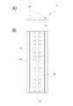
FIG. 1A is a plan view of a packaging bag 1 showing an example of the present invention, and FIG. 1B is a sectional view taken along line XX in FIG. As shown in FIG. 1, the packaging bag 1 includes a container
容器本体11は、表面フィルム111と裏面フィルム112とにより構成され、四角縁部がヒートシールされ、そのヒートシールされた側端縁の上部にノッチ113を有している。また、封止部材12は、容器本体の内方に折り込まれ、折れ線121に沿って非貫通状態に薄肉化された開封予定線122を容器本体の中心側(内容物収納部側)に面して具備すると共に、開封予定線122に平行して設けられた一対の凹溝部と凸条部とからなる再封手段124を、容器本体の上端縁側に面して具備している。
The container
図2は封止部材12の折り込まない状態の側面図及び平面図である。図2に示すように封止部材12は、長さ方向に沿って非貫通状態に薄肉化されて設けられた開封予定線122と、これに交差して非貫通状態に薄肉化されて形成された複数の開封補助線123と、開封予定線122に平行して設けられた一対の凹溝部と凸条部とからなる再封手段124を具備している。
FIG. 2 is a side view and a plan view of the state in which the sealing
ここで、再封手段124は封止部材12に一体に成型され、又は、封止部材12上に固着されている。また、封止部材12の長さ方向両側端部は、再封手段124が内側となるように折り込まれ、容器本体11の両側辺において、表面フィルム111又は裏面フィルム112にヒートシールされて固着される。なお、固着の手段としては、特に制限されるものではなく、接着剤を用いた接着などを適宜採用し得る。
Here, the resealing means 124 is molded integrally with the sealing
本発明の包装袋1の製造方法について説明する。
第一に、表面フィルム111及び裏面フィルム112を、それぞれドライラミネート法を用いてラミネートし作製した。ここでは、表面フィルム111及び裏面フィルム112のいずれも、未延伸のポリプロピレンフィルム(厚み60μm)と二軸延伸ナイロンフィルム(厚み15μm)と二軸延伸PETフィルム(厚み12μm)の積層フィルムとした。ここで、ポリプロピレンフィルム層がヒートシール層となる。
The manufacturing method of the packaging bag 1 of this invention is demonstrated.
First, the
第二に、図2に図示する封止部材12を作製した。封止部材12は、凹溝部と凸条部とが係合する再封手段124、及び薄肉部である開封予定線122を備えたポリプロピレン製のチャックシート125(基材シート厚み380μm)に対し、開封補助線123をレーザー加工により形成して作製した。なお、上記チャックシート125は、押出成型や射出成型などの公知の方法で成型し得る。
Second, the sealing
ここで、上記封止部材12の作製に際し、非貫通状態に薄肉部が形成された開封補助線123を形成する際のレーザー加工の条件は以下の通りである。
使用装置:ROFIN−BAASEL社製StarScribeEasy(CO2レーザー発振器)
レーザー周波数:10000Hz
レーザー走査速度:2000mm/s
レーザー出力:15%
Here, when the sealing
Equipment used: Starscribe Easy (CO 2 laser oscillator) manufactured by ROFIN-BAASEL
Laser frequency: 10000Hz
Laser scanning speed: 2000 mm / s
Laser power: 15%
そして、上記実施例において、図3(A)に示すように、レーザー加工時のレーザー焦点211を開封予定線122の薄肉部の上部側へ離間して設定した。このようにすることにより、開封補助線123を基材シートに対し、確実に非貫通状態に形成することができ、特に開封予定線122と開封補助線123との交差部分についても安定的に非貫通状態に形成することができた。結果として、開封予定線122の薄肉部厚みに近い開封補助線123の残留シート厚み(薄肉部が形成された後に残留するシート厚み)の封止部材12を得た。
And in the said Example, as shown to FIG. 3 (A), the
上記チャックシート125に対して、レーザー加工により開封補助線123を形成する様子を図3に示す。
レーザー光21は、チャックシート125の表面に形成された開封予定線122に面する側から照射されても(図3(A))、その裏面側から照射されても(図3(B))良い。また、いずれも図3においてレーザー焦点211は開封予定線122の薄肉部溝の底部位置から溝の上部側へ離間した位置に設定されている。なお、レーザー光21の焦点211の位置は、レンズ22の位置取りによって変更可能なものである。
FIG. 3 shows how the
The
そして、第三に、図1に示す容器本体11を作製した。上記再封手段124の一対の凹溝部と凸条部とが係合し得るように封止部材12の開封予定線122に沿って折り曲げられた封止部材12を、ヒートシール層が対向するように重ね合わせた表面フィルム111と裏面フィルム112との間に、上部に封止部材12が存在しない部分が残るように封止部材12を上端から離間させて挿入し挟持して、全周縁をヒートシールした。また、容器本体の下部に注出口13を表面フィルム111と裏面フィルム112との間に挟持した状態で、表面フィルム111及び裏面フィルム112の全周縁をヒートシールすることにより、容器本体11を形成すると共に封止部材12,注出口13を容器本体11に固定した。
Third, the
最後に、容器本体11の上部において、封止部材12の存在しない両側辺のヒートシール部にノッチ113を設けて図1に示す包装袋1を完成した。この包装袋は流動食などの医療用液体を収納するのに好適なものである。
Finally,
なお、包装袋1の内容物充填方法は種々の方法を採用することができる。例えば、表面フィルム111及び裏面フィルム112の周縁をシールする際に、一辺を残して内容物充填口を確保した状態でヒートシールし、内容物充填口を通じて内容物を充填した後に、内容物充填口をヒートシールしても良いし、本実施例のような注出口付の袋の場合には、包装袋1を形成後、開閉自在な注出口13を介して内容物を充填・再密封しても良い。
また、内容物が充填された包装袋では、再封手段124は係合されていても、係合されていなくても良いが、内容物が流動食など液体である場合、輸送時の内容物の流動により、閉じたり開いたりすることで、封止部材12の開封予定線122が破断してしまうおそれがあるので、再封手段124は係合されていることが望ましい。
Various methods can be adopted as the method for filling the contents of the packaging bag 1. For example, when sealing the peripheral edges of the
Further, in the packaging bag filled with the contents, the resealing means 124 may or may not be engaged. However, when the contents are liquid such as liquid food, the contents during transportation The resealing means 124 is preferably engaged because the
包装袋1の使用方法としては、第一に、内容物が充填された包装袋1の側端部に設けられたノッチ113から包装袋1を開口する。第二に、上記再封手段124が係合されている場合には係合を解除する。最後に、上記封止部材12に設けられた開封予定線122に沿って力が加わるように、包装袋内部に指を押し込むように、局所的に力をかけ、開封予定線122に沿った裂け目を形成することにより、封止部材12も開口し、包装袋1に充填された内容物を包装袋外に取り出すことや包装袋内に他の物品を導入することが可能となる。上記包装袋1はそのような裂け目の形成が容易であり、従って実用性に富む包装袋である。
As a method of using the packaging bag 1, first, the packaging bag 1 is opened from a
以上、本発明について、実施例をもとに説明したが、本発明の趣旨を損なわない範囲で適宜変更することが可能である。包装体の形状、封止手段の形状、注出口の有無、注出口の設置場所等についても限定されるものではない。例えば、開封線予定線や開封補助線は連続した薄肉部の形成にこだわる必要はなく、断続するものであっても良い。また、包装袋に印刷層を設けたり、注出口を下端縁中央部に設けたりしても良い。
また、開封線予定線及び/又は開封補助線の形成に際しては、レーザー以外の手段、例えば、鋭利な刃物を有するN/C工作機械を用いて形成する方法を採用しても良い。
While the present invention has been described based on the embodiments, it can be changed as appropriate without departing from the spirit of the present invention. The shape of the package, the shape of the sealing means, the presence or absence of the spout, the installation location of the spout, etc. are not limited. For example, it is not necessary to stick to the formation of continuous thin-walled portions, and the planned opening line and the opening assist line may be intermittent. Moreover, a printing layer may be provided in a packaging bag, or a spout may be provided in the center part of a lower end edge.
Moreover, when forming the opening line and / or the auxiliary opening line, a method of forming using means other than laser, for example, an N / C machine tool having a sharp blade may be employed.
1 包装袋
11 容器本体
12 封止部材
121 折れ線
122 開封予定線
123 開封補助線
124 再封手段
125 チャックシート
DESCRIPTION OF SYMBOLS 1
Claims (9)
9. The method for manufacturing a packaging bag according to claim 8, wherein a laser focus at the time of laser processing is set outside the sealing member.
Priority Applications (1)
| Application Number | Priority Date | Filing Date | Title |
|---|---|---|---|
| JP2006097108A JP2007269362A (en) | 2006-03-31 | 2006-03-31 | Packaging bag and manufacturing method thereof |
Applications Claiming Priority (1)
| Application Number | Priority Date | Filing Date | Title |
|---|---|---|---|
| JP2006097108A JP2007269362A (en) | 2006-03-31 | 2006-03-31 | Packaging bag and manufacturing method thereof |
Publications (1)
| Publication Number | Publication Date |
|---|---|
| JP2007269362A true JP2007269362A (en) | 2007-10-18 |
Family
ID=38672560
Family Applications (1)
| Application Number | Title | Priority Date | Filing Date |
|---|---|---|---|
| JP2006097108A Pending JP2007269362A (en) | 2006-03-31 | 2006-03-31 | Packaging bag and manufacturing method thereof |
Country Status (1)
| Country | Link |
|---|---|
| JP (1) | JP2007269362A (en) |
Cited By (5)
| Publication number | Priority date | Publication date | Assignee | Title |
|---|---|---|---|---|
| WO2010024241A1 (en) * | 2008-08-26 | 2010-03-04 | 出光ユニテック株式会社 | Zipper tape and packaging bag with zipper tape |
| JP2010137866A (en) * | 2008-12-09 | 2010-06-24 | Idemitsu Unitech Co Ltd | Packaging bag with zipper tape, device and method for manufacturing the same, and foldable strip-like member |
| JP2016199302A (en) * | 2015-04-13 | 2016-12-01 | 凸版印刷株式会社 | Pouch with fastener |
| JP2018002303A (en) * | 2016-12-02 | 2018-01-11 | 株式会社ミューパック・オザキ | Packaging bag |
| JP2018015906A (en) * | 2016-07-25 | 2018-02-01 | 凸版印刷株式会社 | LAMINATED FILM, ITS MANUFACTURING METHOD, AND PACKAGING BAG |
-
2006
- 2006-03-31 JP JP2006097108A patent/JP2007269362A/en active Pending
Cited By (6)
| Publication number | Priority date | Publication date | Assignee | Title |
|---|---|---|---|---|
| WO2010024241A1 (en) * | 2008-08-26 | 2010-03-04 | 出光ユニテック株式会社 | Zipper tape and packaging bag with zipper tape |
| US8646972B2 (en) | 2008-08-26 | 2014-02-11 | Idemitsu Unitech Co., Ltd. | Zipper tape and packaging bag with zipper tape |
| JP2010137866A (en) * | 2008-12-09 | 2010-06-24 | Idemitsu Unitech Co Ltd | Packaging bag with zipper tape, device and method for manufacturing the same, and foldable strip-like member |
| JP2016199302A (en) * | 2015-04-13 | 2016-12-01 | 凸版印刷株式会社 | Pouch with fastener |
| JP2018015906A (en) * | 2016-07-25 | 2018-02-01 | 凸版印刷株式会社 | LAMINATED FILM, ITS MANUFACTURING METHOD, AND PACKAGING BAG |
| JP2018002303A (en) * | 2016-12-02 | 2018-01-11 | 株式会社ミューパック・オザキ | Packaging bag |
Similar Documents
| Publication | Publication Date | Title |
|---|---|---|
| JP5958214B2 (en) | Packaging bag | |
| WO2015072404A1 (en) | Container body, container, and method for producing container | |
| JP2005206162A (en) | Pouch with spout | |
| JPH10305850A (en) | Packaging bag with spout | |
| JP4280609B2 (en) | Package and method for producing the same | |
| JP2006199337A (en) | Gusset packaging bag | |
| JP2007269362A (en) | Packaging bag and manufacturing method thereof | |
| JP2006123949A (en) | Liquid filled container | |
| JP2017114546A (en) | Spout union and container with spout union | |
| JPH11278556A (en) | Packaging bag | |
| JP2006193173A (en) | Packaging bag and manufacturing method thereof | |
| JP4489515B2 (en) | Perforation | |
| JP5463560B2 (en) | Refillable pouch | |
| JP4769421B2 (en) | Easy-to-open gusset type packaging bag | |
| JP2003002341A (en) | Bag with member for drinking spout | |
| CN104159729A (en) | Packaging material, package produced therefrom and method for constructing the package | |
| JP6238429B2 (en) | Packaging bag | |
| JPH11198949A (en) | Easily unsealable pouch | |
| JP2004359293A (en) | Easy-open packaging bag and manufacturing method thereof | |
| JP2019156462A (en) | Packaging bag | |
| JP2015199523A (en) | Packaging bag | |
| JP6012966B2 (en) | Container with spout | |
| JP2003182754A (en) | Sealed spout | |
| JP6769197B2 (en) | Packaging bag | |
| JP6772705B2 (en) | Packaging bag |