JP2007146946A - High pressure tank - Google Patents
High pressure tank Download PDFInfo
- Publication number
- JP2007146946A JP2007146946A JP2005341003A JP2005341003A JP2007146946A JP 2007146946 A JP2007146946 A JP 2007146946A JP 2005341003 A JP2005341003 A JP 2005341003A JP 2005341003 A JP2005341003 A JP 2005341003A JP 2007146946 A JP2007146946 A JP 2007146946A
- Authority
- JP
- Japan
- Prior art keywords
- ring
- backup
- backup ring
- mounting groove
- pressure tank
- Prior art date
- Legal status (The legal status is an assumption and is not a legal conclusion. Google has not performed a legal analysis and makes no representation as to the accuracy of the status listed.)
- Pending
Links
Images


Classifications
-
- F—MECHANICAL ENGINEERING; LIGHTING; HEATING; WEAPONS; BLASTING
- F16—ENGINEERING ELEMENTS AND UNITS; GENERAL MEASURES FOR PRODUCING AND MAINTAINING EFFECTIVE FUNCTIONING OF MACHINES OR INSTALLATIONS; THERMAL INSULATION IN GENERAL
- F16J—PISTONS; CYLINDERS; SEALINGS
- F16J15/00—Sealings
- F16J15/02—Sealings between relatively-stationary surfaces
- F16J15/06—Sealings between relatively-stationary surfaces with solid packing compressed between sealing surfaces
- F16J15/10—Sealings between relatively-stationary surfaces with solid packing compressed between sealing surfaces with non-metallic packing
- F16J15/104—Sealings between relatively-stationary surfaces with solid packing compressed between sealing surfaces with non-metallic packing characterised by structure
-
- F—MECHANICAL ENGINEERING; LIGHTING; HEATING; WEAPONS; BLASTING
- F16—ENGINEERING ELEMENTS AND UNITS; GENERAL MEASURES FOR PRODUCING AND MAINTAINING EFFECTIVE FUNCTIONING OF MACHINES OR INSTALLATIONS; THERMAL INSULATION IN GENERAL
- F16J—PISTONS; CYLINDERS; SEALINGS
- F16J15/00—Sealings
- F16J15/46—Sealings with packing ring expanded or pressed into place by fluid pressure, e.g. inflatable packings
- F16J15/48—Sealings with packing ring expanded or pressed into place by fluid pressure, e.g. inflatable packings influenced by the pressure within the member to be sealed
Landscapes
- Engineering & Computer Science (AREA)
- General Engineering & Computer Science (AREA)
- Mechanical Engineering (AREA)
- Physics & Mathematics (AREA)
- Architecture (AREA)
- Fluid Mechanics (AREA)
- Filling Or Discharging Of Gas Storage Vessels (AREA)
- Gasket Seals (AREA)
- Sealing Devices (AREA)
- Pressure Vessels And Lids Thereof (AREA)
Abstract
【課題】取付溝とバックアップリングとの隙間を埋めることができ、且つ、製造の容易な高圧タンクを提供する。
【解決手段】Oリング100を介して高圧側から押圧されることによって、第一バックアップリング90と第二バックアップリング92は、重ね合わされたテーパ面によって互いに異なる方向へ摺動する。つまり、第一バックアップリング90は口金20側に向かってスライドし、一方、第二バックアップリング92はバルブ32側に向かってスライドする。その結果、(A)の状態で存在していた各バックアップリングとリング取付溝80との隙間82が、(B)の状態では各バックアップリングによって埋められている。また、リング取付溝80は、比較的単純な矩形状断面に加工すればよいため、加工も容易である。
【選択図】図2A high-pressure tank that can fill a gap between a mounting groove and a backup ring and is easy to manufacture.
By being pressed from the high pressure side via an O-ring 100, a first backup ring 90 and a second backup ring 92 slide in different directions by the overlapped tapered surfaces. That is, the first backup ring 90 slides toward the base 20 side, while the second backup ring 92 slides toward the valve 32 side. As a result, the gap 82 between each backup ring and the ring mounting groove 80 existing in the state (A) is filled with each backup ring in the state (B). Further, since the ring mounting groove 80 may be processed into a relatively simple rectangular cross section, the processing is easy.
[Selection] Figure 2
Description
本発明は、高圧タンクに関し、特に高圧タンクのシール構造に関する。 The present invention relates to a high pressure tank, and more particularly to a high pressure tank seal structure.
従来から、車両用の燃料ガスなどを充填するための高圧タンクが知られている。高圧タンク内には、高圧力の燃料ガスが充填されるため、例えば、バルブと口金との接合部分などに、高圧力に耐えながら燃料ガスなどを密閉するシール構造が設けられる。なお、シール構造に関しては、高圧タンクに設けられるものに限らず、従来から様々な技術が提案されている。 Conventionally, a high-pressure tank for filling a vehicle fuel gas or the like is known. Since the high-pressure tank is filled with high-pressure fuel gas, for example, a sealing structure that seals the fuel gas or the like while withstanding high pressure is provided at the joint between the valve and the base. In addition, regarding a seal structure, not only what is provided in a high pressure tank but the various techniques are proposed conventionally.
例えば、特許文献1には、テーパ状溝底部を有する取付溝内に、そのテーパ状溝底部に対応したテーパ部を備えたバックアップリングを設ける技術が記載されている。これにより、シールリングを介して高圧側から押圧されたバックアップリングがテーパ面に沿ってスライドし、バックアップリングと取付溝との隙間が埋められる。 For example, Patent Document 1 describes a technique in which a backup ring having a tapered portion corresponding to a tapered groove bottom portion is provided in a mounting groove having a tapered groove bottom portion. Thereby, the backup ring pressed from the high pressure side through the seal ring slides along the tapered surface, and the gap between the backup ring and the mounting groove is filled.
上述のように、例えば、特許文献1には、取付溝内のテーパ状溝底部にバックアップリングのテーパ部を対応させる技術が開示されている。しかし、特許文献1の技術は、内燃機関のインジェクタの配管部などに用いられる密閉装置に関するものであり、高圧タンクのシール構造に関するものではない。仮に、高圧タンクのシール構造に適用できたとしても、取付溝内にテーパ状溝底部を設けることは、取付溝の加工を困難にする。 As described above, for example, Patent Document 1 discloses a technique in which the tapered portion of the backup ring is made to correspond to the tapered groove bottom portion in the mounting groove. However, the technique of Patent Document 1 relates to a sealing device used for a piping portion of an injector of an internal combustion engine, and not to a sealing structure of a high-pressure tank. Even if it can be applied to the seal structure of the high-pressure tank, providing the tapered groove bottom in the mounting groove makes it difficult to process the mounting groove.
本発明は、このような背景において成されたものであり、その目的は、取付溝とバックアップリングとの隙間を埋めることができ、且つ、製造の容易な高圧タンクを提供することにある。 The present invention has been made in such a background, and an object of the present invention is to provide a high-pressure tank that can fill the gap between the mounting groove and the backup ring and is easy to manufacture.
上記目的を達成するために、本発明の好適な態様である高圧タンクは、シールリングと、各々がテーパ面を備えた第一および第二バックアップリングと、を取付溝内に設けた高圧タンクであって、前記第一および第二バックアップリングは、互いのテーパ面を重ね合わせて前記シールリングよりも低圧側に配置され、前記シールリングを介して高圧側から押圧されることによって、前記第一および第二バックアップリングがテーパ面によって互いに異なる方向へ摺動する、ことを特徴とする。 In order to achieve the above object, a high-pressure tank according to a preferred embodiment of the present invention is a high-pressure tank in which a seal ring and first and second backup rings each having a tapered surface are provided in a mounting groove. The first and second backup rings are arranged on the lower pressure side than the seal ring with the taper surfaces of the first and second backup rings being overlapped, and are pressed from the high pressure side via the seal ring. The second backup ring is slid in different directions by the tapered surface.
上記構成では、取付溝内に設けられた第一および第二バックアップリングが互いに異なる方向へ摺動する。例えば、各バックアップリングが取付溝の壁面へ向かって摺動することにより、各バックアップリングと取付溝との隙間を埋めることが可能になる。また、上記構成では、取付溝の壁面にテーパを設ける必要がないため取付溝の加工が容易である。 In the above configuration, the first and second backup rings provided in the mounting groove slide in different directions. For example, by sliding each backup ring toward the wall surface of the mounting groove, it becomes possible to fill a gap between each backup ring and the mounting groove. Moreover, in the said structure, since it is not necessary to provide a taper in the wall surface of an attachment groove, the process of an attachment groove is easy.
望ましい態様において、前記第一および第二バックアップリングは、各々、全周にテーパ面を備える、ことを特徴とする。望ましい態様において、前記シールリングと前記第一および第二バックアップリングは、タンク本体の開口に挿入されるバルブの外周面に形成された円環状の取付溝内に設けられ、バルブの外周面が開口に挿入された状態で、前記第一および第二バックアップリングが互いに異なる方向へ摺動することにより、各バックアップリングと取付溝との隙間が埋められる、ことを特徴とする。 In a preferred aspect, each of the first and second backup rings includes a tapered surface on the entire circumference. In a desirable mode, the seal ring and the first and second backup rings are provided in an annular mounting groove formed on the outer peripheral surface of the valve inserted into the opening of the tank body, and the outer peripheral surface of the valve is opened. When the first and second backup rings are slid in different directions in the inserted state, gaps between the backup rings and the mounting grooves are filled.
また上記目的を達成するために、本発明の好適な態様であるシール構造は、シールリングと、各々がテーパ面を備えた第一および第二バックアップリングと、を取付溝内に設けたシール構造であって、前記第一および第二バックアップリングは、互いのテーパ面を重ね合わせて前記シールリングよりも低圧側に配置され、前記シールリングを介して高圧側から押圧されることによって、前記第一および第二バックアップリングがテーパ面によって互いに異なる方向へ摺動する、ことを特徴とする。 In order to achieve the above object, a seal structure according to a preferred embodiment of the present invention is a seal structure in which a seal ring and first and second backup rings each having a tapered surface are provided in a mounting groove. The first and second backup rings are arranged on the lower pressure side than the seal ring with the taper surfaces of the first and second backup rings overlapped with each other, and are pressed from the high pressure side via the seal ring. The first and second backup rings are slid in different directions by the tapered surface.
本発明により、取付溝とバックアップリングとの隙間を埋めることができ、且つ、製造の容易な高圧タンクが提供される。 The present invention provides a high-pressure tank that can fill the gap between the mounting groove and the backup ring and is easy to manufacture.
以下、本発明の好適な実施形態を図面に基づいて説明する。 DESCRIPTION OF EXEMPLARY EMBODIMENTS Hereinafter, preferred embodiments of the invention will be described with reference to the drawings.
図1は、本発明に係る高圧タンク10の全体構成を説明するための断面図である。まず図1を利用して、本実施形態の高圧タンク10の全体構成について説明する。 FIG. 1 is a cross-sectional view for explaining the overall configuration of a high-pressure tank 10 according to the present invention. First, the overall configuration of the high-pressure tank 10 of the present embodiment will be described with reference to FIG.
本実施形態の高圧タンク10は、内部(タンク内側)に、例えば水素や天然ガスなどの燃料ガスを充填保管するためのものであり、容器状のタンク本体12を備えている。タンク本体12の周壁は、外側の外周壁16と内側の内周壁18で構成されている。内周壁18は、例えば樹脂ライナーでありナイロン樹脂等で形成される。内周壁18は、図1に破線で示される接続部70において、図1の上下に二分割されている。
The high-pressure tank 10 of the present embodiment is for filling and storing fuel gas such as hydrogen or natural gas in the inside (inside the tank), and includes a container-
図1では高圧タンク10の下方側が図示省略されており、図示省略された下方側の内周壁18も上方側と同様に構成され、上下二体の内周壁18がレーザーなどの加熱装置によって接続部70で溶接される。そして、溶接されて一体となった内周壁18の外側に、樹脂(例えばエポキシ樹脂)を含浸させたカーボン繊維をフィラメントワインディングして被覆させ、これを乾燥させることにより、内周壁18と外周壁16の二層構造のタンク本体12が形成される。なお、内周壁18は予め上下一体で形成されてもよい。またタンク本体12に、その角部を保護するウレタン製の保護パッド50が取り付けられてもよい。
In FIG. 1, the lower side of the high-pressure tank 10 is not shown, and the lower inner peripheral wall 18 (not shown) is configured in the same manner as the upper side, and the upper and lower inner
タンク本体12は、金属製の略円筒状とされた口金20を有している。口金20は、例えばステンレスやアルミニウム製である。口金20は、外周壁16と内周壁18に嵌入されて、さらに、口金20は、内周壁18に沿ってタンク内側に向かって突出している。
The
口金20内には、略円柱状の開口が設けられており、これがタンク本体12の開口として機能する。口金20の開口には、略円柱状のバルブ32が取り付けられている。バルブ32の軸方向の中間部分には雄ネジが形成されており、バルブ32の雄ネジが口金20の開口に設けられた雌ネジに締結(螺合)されることで、バルブ32によって口金20の開口が閉じられている。
A substantially cylindrical opening is provided in the
バルブ32と口金20との接触面には、Oリング60が挿入されている。Oリング60は、例えばゴム製などの弾力を有する部材であり、略円柱状のバルブ32を取り囲むように配置されている。そして、このOリング60を介して口金20とバルブ32とが接触することにより、シール性が確保されている。なお、口金20と内周壁18との接触面にもOリング60が設けられており、口金20と内周壁18との間のシール性が確保されている。
An O-
本実施形態の高圧タンク10は、開口部分がタンクの内側に突出している。その内側突出部分では、略円柱状のバルブ32を取り囲むように口金20がタンク内側に向かって突出している。そして、内側突出部分のバルブ32と口金20との接続面において、バルブ32の外周面に円環状のリング取付溝80が設けられている。
As for the high-pressure tank 10 of this embodiment, the opening part protrudes inside the tank. At the inner protruding portion, the
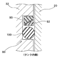
図2は、リング取付溝80内の構成を説明するための図であり、図2(A)(B)は、共に、図1に示すリング取付溝80の右側断面の拡大図である。
FIG. 2 is a view for explaining the configuration in the
図2(A)に示すように、リング取付溝80は、矩形断面に形成されてその内部にOリング100と第一バックアップリング90と第二バックアップリング92が設けられている。Oリング100は、略円柱状のバルブ32を取り囲むシールリングであり、例えばゴム製などの弾力を有する部材で形成される。
As shown in FIG. 2A, the
第一バックアップリング90および第二バックアップリング92は、各々、略円柱状のバルブ32を取り囲むリング状の部材である。第一バックアップリング90および第二バックアップリング92は、例えば樹脂系材料によって形成されることが望ましい。但し、金属などで形成されてもよい。そして、第一バックアップリング90および第二バックアップリング92は、各々、全周にテーパ面が形成され、互いのテーパ面を重ね合わせてリング取付溝80内に収められている。図2の第一バックアップリング90と第二バックアップリング92の断面では、傾斜直線で示される断面部分がテーパ面に対応している。
The
図2(A)の下方側はタンク内側である。タンク内部には、例えば水素や天然ガスなどの燃料ガスが充填されている。燃料ガスはタンク内に高圧力で充填されているため、バルブ32と口金20との間の僅かな隙間に高圧の燃料ガス(高圧ガス)が入り込み、リング取付溝80内に入り込んでしまう。バルブ32と口金20との間の僅かな隙間に入り込む高圧ガスをシールするために、Oリング100が設けられている。つまり、Oリング100がバルブ32と口金20の隙間をシールすることにより、燃料ガスがその隙間からタンク外部へ流出することを防止している。
The lower side of FIG. 2A is the inside of the tank. The tank is filled with fuel gas such as hydrogen or natural gas. Since the fuel gas is filled in the tank at a high pressure, the high-pressure fuel gas (high-pressure gas) enters the slight gap between the
本実施形態では、リング取付溝80内において、Oリング100よりも低圧側、つまり図2(A)の上方側に、第一バックアップリング90および第二バックアップリング92が配置される。図2(A)の状態でリング取付溝80内にタンク内側(高圧側)から高圧ガスが入り込むと、Oリング100が上方側に向かって押圧される。そして、第一バックアップリング90および第二バックアップリング92は、Oリング100を介して、上方側へ向かって押圧される。
In the present embodiment, the
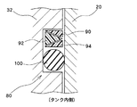
図2(B)は、Oリング100と第一バックアップリング90と第二バックアップリング92が上方側に向かって押圧された状態を示している。Oリング100を介して高圧側から押圧されることによって、第一バックアップリング90と第二バックアップリング92は、重ね合わされたテーパ面によって互いに異なる方向へ摺動する。つまり、Oリング100による押圧方向に対して略垂直な面内に属する互いに逆向きの方向へ摺動する。本実施形態では、第一バックアップリング90は口金20側に向かってスライドし、一方、第二バックアップリング92はバルブ32側に向かってスライドする。
FIG. 2B shows a state where the O-
このように、密閉すべき部材(口金20とバルブ32)と近接する方向(隙間をなくす方向)に各バックアップリングが摺動するため、その結果、図2(A)の状態で存在していた各バックアップリングとリング取付溝80との隙間82が、図2(B)の状態では各バックアップリングによって埋められている。つまり、第一バックアップリング90が口金20側の隙間82を埋めており、また、第二バックアップリング92がバルブ32側の隙間82を埋めている。
As described above, each backup ring slides in the direction close to the member to be sealed (the
このように、各バックアップリングによって隙間82が埋められるため、高圧ガスでOリング100が押圧されて上方に向かって潰された場合でも、Oリング100が隙間82に入り込むことを防ぐことができる。そのため、Oリング100によるシール機能が十分に発揮され、また、Oリング100が隙間82に入り込んでOリング100の一部が損傷することなどを防ぐこともできる。
Thus, since the
このように、本実施形態によって、Oリング100が隙間82に入り込むことを防ぐことができる。さらに、本実施形態では、二つのバックアップリングのテーパ面を利用しているため、リング取付溝80にテーパ面を形成する必要がない。つまり、リング取付溝80は、比較的単純な矩形状断面に加工すればよいため、加工も容易である。
Thus, according to the present embodiment, the O-
なお、図2には、図1に示すリング取付溝80の右側断面のみを図示しているが、リング取付溝80は、円柱状のバルブ32の外周を取り囲むように円環状に形成されている。また、第一バックアップリング90と第二バックアップリング92とOリング100も、各々、円柱状のバルブ32の外周を取り囲むように円環状に形成され、そして、第一バックアップリング90および第二バックアップリング92の各々は、全周に亘ってテーパ面が形成されている。したがって、Oリング100が、図2の上方側に向かって押圧されることによって、第一バックアップリング90が全周に亘って口金20側(つまり径方向の外側)にスライドして隙間82を埋め、また、第二バックアップリング92が全周に亘ってバルブ32側(つまり径方向の内側)にスライドして隙間82を埋めている。
2 shows only the right cross-section of the
図3および図4は、本発明に係るバックアップリングの変形例を示す図であり、図3および図4は、各々、図1に示すリング取付溝80の右側断面の拡大図に相当する。
FIGS. 3 and 4 are views showing modifications of the backup ring according to the present invention, and FIGS. 3 and 4 correspond to enlarged views of a right cross-section of the
図3に示す変形例は、図2に示す第一バックアップリング90と第二バックアップリング92のテーパ面の傾斜方向を反転させた例である。つまり、図3に示す変形例では、Oリング100によって第一バックアップリング90と第二バックアップリング92が上方側に向かって押圧されると、第一バックアップリング90がバルブ32側に向かってスライドし、一方、第二バックアップリング92が口金20に向かってスライドする。つまり、第一バックアップリング90がバルブ32側の隙間を埋め、第二バックアップリング92が口金20側の隙間を埋めることになる。
The modification shown in FIG. 3 is an example in which the inclination directions of the tapered surfaces of the
図4に示す変形例は、第一バックアップリング90と第二バックアップリング92に加えて、第三バックアップリング94を設けた例である。そして、図4に示す変形例では、Oリング100によって第一バックアップリング90と第二バックアップリング92と第三バックアップリング94が上方側に向かって押圧されると、第一バックアップリング90が口金20側に向かってスライドし、第二バックアップリング92がバルブ32側に向かってスライドし、第三バックアップリング94が口金20側に向かってスライドする。つまり、第一バックアップリング90と第三バックアップリング94とによって口金20側の隙間を埋め、第二バックアップリング92がバルブ32側の隙間を埋める。このように、三つのバックアップリングを利用して隙間を埋めることも可能であり、また、必要に応じてさらにバックアップリングを追加してもよい。
The modification shown in FIG. 4 is an example in which a
以上、本発明の好適な実施形態を説明したが、上述した実施形態は、あらゆる点で単なる例示にすぎず、本発明の範囲を限定するものではない。 As mentioned above, although preferred embodiment of this invention was described, embodiment mentioned above is only a mere illustration in all the points, and does not limit the scope of the present invention.
例えば、図2から図4には、Oリング100の上方側にバックアップリングを設ける実施形態を示したが、Oリング100の下方側にバックアップリングを設けてもよい。例えば、図2において、Oリング100の上方側に加えて下方側にも第一バックアップリング90と第二バックアップリング92を設けてもよい。これにより、Oリング100の上方側が高圧となり下方側に向かってOリング100が押圧される場合でも、下方側に設けられる第一バックアップリング90と第二バックアップリング92によって、Oリング100が隙間に入り込むことを防ぐことができる。
For example, FIGS. 2 to 4 show an embodiment in which a backup ring is provided on the upper side of the O-
また、本発明に係るバックアップリングは、バルブと口金との間に設けられる用途に限定されない。例えば、バルブ内に設けられたガス流路周辺などのシール部分において、本発明に係るバックアップリングが利用されてもよい。さらに、本発明に係るバックアップリングは、高圧タンクに限らず、流体などを封止することにより、シールの下流と上流で圧力差が生じる構成であれば、如何なるシールにも適用可能である。 Further, the backup ring according to the present invention is not limited to the use provided between the valve and the base. For example, the backup ring according to the present invention may be used in a seal portion such as around the gas flow path provided in the valve. Furthermore, the backup ring according to the present invention is not limited to a high-pressure tank, and can be applied to any seal as long as a pressure difference is generated between the downstream and upstream of the seal by sealing a fluid or the like.
10 高圧タンク、80 リング取付溝、82 隙間、90 第一バックアップリング、92 第二バックアップリング、100 Oリング。 10 high pressure tank, 80 ring mounting groove, 82 gap, 90 first backup ring, 92 second backup ring, 100 O ring.
Claims (4)
各々がテーパ面を備えた第一および第二バックアップリングと、
を取付溝内に設けた高圧タンクであって、
前記第一および第二バックアップリングは、互いのテーパ面を重ね合わせて前記シールリングよりも低圧側に配置され、
前記シールリングを介して高圧側から押圧されることによって、前記第一および第二バックアップリングがテーパ面によって互いに異なる方向へ摺動する、
ことを特徴とする高圧タンク。 A seal ring;
First and second backup rings each having a tapered surface;
Is a high-pressure tank provided in the mounting groove,
The first and second backup rings are arranged on the lower pressure side than the seal ring by overlapping the taper surfaces of each other,
By being pressed from the high pressure side through the seal ring, the first and second backup rings slide in different directions by the tapered surface,
A high-pressure tank characterized by that.
前記第一および第二バックアップリングは、各々、全周にテーパ面を備える、
ことを特徴とする高圧タンク。 The high-pressure tank according to claim 1,
The first and second backup rings each have a tapered surface on the entire circumference,
A high-pressure tank characterized by that.
前記シールリングと前記第一および第二バックアップリングは、タンク本体の開口に挿入されるバルブの外周面に形成された円環状の取付溝内に設けられ、
バルブの外周面が開口に挿入された状態で、前記第一および第二バックアップリングが互いに異なる方向へ摺動することにより、各バックアップリングと取付溝との隙間が埋められる、
ことを特徴とする高圧タンク。 The high-pressure tank according to claim 2,
The seal ring and the first and second backup rings are provided in an annular mounting groove formed on the outer peripheral surface of the valve inserted into the opening of the tank body,
With the outer peripheral surface of the valve inserted into the opening, the first and second backup rings slide in different directions, thereby filling the gap between each backup ring and the mounting groove.
A high-pressure tank characterized by that.
各々がテーパ面を備えた第一および第二バックアップリングと、
を取付溝内に設けたシール構造であって、
前記第一および第二バックアップリングは、互いのテーパ面を重ね合わせて前記シールリングよりも低圧側に配置され、
前記シールリングを介して高圧側から押圧されることによって、前記第一および第二バックアップリングがテーパ面によって互いに異なる方向へ摺動する、
ことを特徴とするシール構造。 A seal ring;
First and second backup rings each having a tapered surface;
In the mounting groove,
The first and second backup rings are arranged on the lower pressure side than the seal ring by overlapping the taper surfaces of each other,
By being pressed from the high pressure side through the seal ring, the first and second backup rings slide in different directions by the tapered surface,
A seal structure characterized by that.
Priority Applications (1)
| Application Number | Priority Date | Filing Date | Title |
|---|---|---|---|
| JP2005341003A JP2007146946A (en) | 2005-11-25 | 2005-11-25 | High pressure tank |
Applications Claiming Priority (1)
| Application Number | Priority Date | Filing Date | Title |
|---|---|---|---|
| JP2005341003A JP2007146946A (en) | 2005-11-25 | 2005-11-25 | High pressure tank |
Publications (1)
| Publication Number | Publication Date |
|---|---|
| JP2007146946A true JP2007146946A (en) | 2007-06-14 |
Family
ID=38208585
Family Applications (1)
| Application Number | Title | Priority Date | Filing Date |
|---|---|---|---|
| JP2005341003A Pending JP2007146946A (en) | 2005-11-25 | 2005-11-25 | High pressure tank |
Country Status (1)
| Country | Link |
|---|---|
| JP (1) | JP2007146946A (en) |
Cited By (16)
| Publication number | Priority date | Publication date | Assignee | Title |
|---|---|---|---|---|
| JP2010190314A (en) * | 2009-02-18 | 2010-09-02 | Nok Corp | Sealing device |
| JP2013228019A (en) * | 2012-04-25 | 2013-11-07 | Toyota Motor Corp | Gas filling device, gas tank inspection device and gas tank inspection method |
| WO2014046288A1 (en) * | 2012-09-21 | 2014-03-27 | Nok株式会社 | Sealing device |
| KR101429592B1 (en) | 2013-05-03 | 2014-08-14 | 국방과학연구소 | Self Sealing Sustaining Pressure Discharge Activation Unit |
| EP3081834A1 (en) * | 2015-04-15 | 2016-10-19 | Teledyne Isco | High pressure pump seal support |
| DE102015009035A1 (en) | 2015-07-11 | 2017-01-12 | Daimler Ag | Radial sealing system |
| JP2017075671A (en) * | 2015-10-16 | 2017-04-20 | Nok株式会社 | Seal structure of pressure vessel |
| KR20170110321A (en) * | 2016-03-23 | 2017-10-11 | 현대자동차주식회사 | Self tighten sealing end plug |
| CN108291650A (en) * | 2015-12-15 | 2018-07-17 | Nok株式会社 | Sealing device |
| JP2018112186A (en) * | 2016-12-21 | 2018-07-19 | ローベルト ボッシュ ゲゼルシャフト ミット ベシュレンクテル ハフツング | Valve for metering fluid, connecting part for valve, and configuration including valve |
| JP2018151047A (en) * | 2017-03-15 | 2018-09-27 | 本田技研工業株式会社 | High pressure tank |
| JP2019056396A (en) * | 2017-09-20 | 2019-04-11 | トヨタ自動車株式会社 | High pressure vessel |
| JP2019108952A (en) * | 2017-12-19 | 2019-07-04 | 豊田合成株式会社 | High pressure tank |
| CN110030441A (en) * | 2019-05-14 | 2019-07-19 | 扬州赛普润橡塑有限公司 | A kind of pipeline rubber seal |
| DE102019109891A1 (en) | 2018-04-16 | 2019-10-17 | Toyoda Gosei Co., Ltd. | Sealing structure of a high-pressure tank |
| JP2024070795A (en) * | 2022-11-11 | 2024-05-23 | ドクサン エーテルシーティー カンパニー リミテッド | Pressure vessels |
Citations (2)
| Publication number | Priority date | Publication date | Assignee | Title |
|---|---|---|---|---|
| JPS4631623Y1 (en) * | 1967-12-26 | 1971-11-01 | ||
| JP2005048918A (en) * | 2003-07-31 | 2005-02-24 | Toyota Motor Corp | tank |
-
2005
- 2005-11-25 JP JP2005341003A patent/JP2007146946A/en active Pending
Patent Citations (2)
| Publication number | Priority date | Publication date | Assignee | Title |
|---|---|---|---|---|
| JPS4631623Y1 (en) * | 1967-12-26 | 1971-11-01 | ||
| JP2005048918A (en) * | 2003-07-31 | 2005-02-24 | Toyota Motor Corp | tank |
Cited By (25)
| Publication number | Priority date | Publication date | Assignee | Title |
|---|---|---|---|---|
| JP2010190314A (en) * | 2009-02-18 | 2010-09-02 | Nok Corp | Sealing device |
| JP2013228019A (en) * | 2012-04-25 | 2013-11-07 | Toyota Motor Corp | Gas filling device, gas tank inspection device and gas tank inspection method |
| WO2014046288A1 (en) * | 2012-09-21 | 2014-03-27 | Nok株式会社 | Sealing device |
| JP5556978B1 (en) * | 2012-09-21 | 2014-07-23 | Nok株式会社 | Sealing device |
| KR20150045486A (en) * | 2012-09-21 | 2015-04-28 | 엔오케이 가부시키가이샤 | Sealing device |
| US9273655B2 (en) | 2012-09-21 | 2016-03-01 | Nok Corporation | Sealing device |
| KR101723367B1 (en) | 2012-09-21 | 2017-04-05 | 엔오케이 가부시키가이샤 | Sealing device |
| KR101429592B1 (en) | 2013-05-03 | 2014-08-14 | 국방과학연구소 | Self Sealing Sustaining Pressure Discharge Activation Unit |
| EP3081834A1 (en) * | 2015-04-15 | 2016-10-19 | Teledyne Isco | High pressure pump seal support |
| DE102015009035A1 (en) | 2015-07-11 | 2017-01-12 | Daimler Ag | Radial sealing system |
| JP2017075671A (en) * | 2015-10-16 | 2017-04-20 | Nok株式会社 | Seal structure of pressure vessel |
| CN108291650A (en) * | 2015-12-15 | 2018-07-17 | Nok株式会社 | Sealing device |
| KR102429160B1 (en) * | 2016-03-23 | 2022-08-03 | 현대자동차주식회사 | Self tighten sealing end plug |
| KR20170110321A (en) * | 2016-03-23 | 2017-10-11 | 현대자동차주식회사 | Self tighten sealing end plug |
| JP2018112186A (en) * | 2016-12-21 | 2018-07-19 | ローベルト ボッシュ ゲゼルシャフト ミット ベシュレンクテル ハフツング | Valve for metering fluid, connecting part for valve, and configuration including valve |
| JP2018151047A (en) * | 2017-03-15 | 2018-09-27 | 本田技研工業株式会社 | High pressure tank |
| JP2019056396A (en) * | 2017-09-20 | 2019-04-11 | トヨタ自動車株式会社 | High pressure vessel |
| JP2019108952A (en) * | 2017-12-19 | 2019-07-04 | 豊田合成株式会社 | High pressure tank |
| DE102019109891A1 (en) | 2018-04-16 | 2019-10-17 | Toyoda Gosei Co., Ltd. | Sealing structure of a high-pressure tank |
| DE102019109891B4 (en) | 2018-04-16 | 2020-08-06 | Toyoda Gosei Co., Ltd. | Sealing structure of a high pressure tank |
| US10890256B2 (en) | 2018-04-16 | 2021-01-12 | Toyoda Gosei Co., Ltd. | Seal structure of high-pressure tank |
| CN110030441A (en) * | 2019-05-14 | 2019-07-19 | 扬州赛普润橡塑有限公司 | A kind of pipeline rubber seal |
| CN110030441B (en) * | 2019-05-14 | 2023-11-17 | 扬州赛普润橡塑有限公司 | Rubber sealing ring for pipeline |
| JP2024070795A (en) * | 2022-11-11 | 2024-05-23 | ドクサン エーテルシーティー カンパニー リミテッド | Pressure vessels |
| JP7652444B2 (en) | 2022-11-11 | 2025-03-27 | ドクサン エーテルシーティー カンパニー リミテッド | Pressure vessels |
Similar Documents
| Publication | Publication Date | Title |
|---|---|---|
| JP4392804B2 (en) | Pressure vessel | |
| JP2007146946A (en) | High pressure tank | |
| JP4935117B2 (en) | tank | |
| JP7371707B2 (en) | high pressure vessel | |
| CN104776315B (en) | The interface structure of pressure vessel | |
| KR101806643B1 (en) | Multi-sealed nozzle and pressure vessel comprising the same | |
| US7556171B2 (en) | Tank | |
| KR102356674B1 (en) | Boss for pressure vessel | |
| JP4525021B2 (en) | tank | |
| JP7017990B2 (en) | Gasket mounting structure for fluid devices | |
| CN108626394A (en) | High pressure storage tank | |
| JP2010133464A (en) | Sealing structure | |
| US12031675B2 (en) | High-pressure tank | |
| JP2011017379A (en) | Gas tank | |
| CN112393111A (en) | Bottleneck seal structure and high-pressure composite container | |
| JP6869105B2 (en) | Gasket and sealing structure | |
| JP6889822B2 (en) | High pressure container | |
| JP2008014342A (en) | tank | |
| JP2017075671A (en) | Seal structure of pressure vessel | |
| JP2009121624A (en) | Gas tank | |
| JPH01234664A (en) | Tappet | |
| JP5858881B2 (en) | Fuel tank with coupling structure | |
| JP7134471B2 (en) | Vehicle fuel supply pipe | |
| JP2008303966A (en) | O-ring assembly structure, high-pressure tank, and high-pressure tank manufacturing method | |
| KR20260051981A (en) | Pressure vessel for storing pressurized fluids such as hydrogen |
Legal Events
| Date | Code | Title | Description |
|---|---|---|---|
| A621 | Written request for application examination |
Free format text: JAPANESE INTERMEDIATE CODE: A621 Effective date: 20080111 |
|
| A131 | Notification of reasons for refusal |
Free format text: JAPANESE INTERMEDIATE CODE: A131 Effective date: 20100622 |
|
| A977 | Report on retrieval |
Free format text: JAPANESE INTERMEDIATE CODE: A971007 Effective date: 20100624 |
|
| A02 | Decision of refusal |
Free format text: JAPANESE INTERMEDIATE CODE: A02 Effective date: 20110104 |