JP2007136785A - Recording device - Google Patents
Recording device Download PDFInfo
- Publication number
- JP2007136785A JP2007136785A JP2005331756A JP2005331756A JP2007136785A JP 2007136785 A JP2007136785 A JP 2007136785A JP 2005331756 A JP2005331756 A JP 2005331756A JP 2005331756 A JP2005331756 A JP 2005331756A JP 2007136785 A JP2007136785 A JP 2007136785A
- Authority
- JP
- Japan
- Prior art keywords
- ink
- head carriage
- tube
- recording
- head
- Prior art date
- Legal status (The legal status is an assumption and is not a legal conclusion. Google has not performed a legal analysis and makes no representation as to the accuracy of the status listed.)
- Withdrawn
Links
Images


Landscapes
- Ink Jet (AREA)
Abstract
Description
本発明はインクジェットプリンタに関するもので、主走査する記録ヘッドに本体に固定されたインクタンクからインクチューブを介してインクを供給する方式のプリンタにおける、インクチューブの支持方法に関するものである。 The present invention relates to an ink jet printer, and more particularly to a method of supporting an ink tube in a printer that supplies ink through an ink tube from an ink tank fixed to a main body to a recording head for main scanning.
従来、キャリッジに搭載された記録ヘッドにインクを供給するインクチューブは束ねられた状態で引き回され、引き回し位置を安定させるために帯状の金属板などに結束されていた。 Conventionally, an ink tube that supplies ink to a recording head mounted on a carriage is drawn in a bundled state, and is bound to a belt-like metal plate or the like in order to stabilize the drawing position.
従来例としては、例えば特許文献1と特許文献2をあげることが出来る。
特に、A2サイズ以上のインクジェットプリンタにおいては、主走査する記録ヘッドに本体に固定されたインクタンクからインクをインクチューブを介して供給しているが、インクチューブを安定的に支持して、ヘッドキャリッジの主走査によるインクチューブの振動による印字品位の低下を回避するとともに、軽量な支持構成で主走査の負荷を軽減し、かつ低コストな構造を提供することにある。 In particular, in an A2 size or larger ink jet printer, ink is supplied from an ink tank fixed to the main body to a recording head for main scanning via an ink tube. In addition to avoiding a drop in print quality due to vibration of the ink tube due to the main scanning, it is possible to reduce the main scanning load with a lightweight support structure and to provide a low-cost structure.
上記課題を解決するために、本発明においては、インクを吐出して記録を行う記録ヘッドを保持し、プラテン上を搬送される記録用紙の搬送方向と直行する方向に走査するヘッドキャリッジと、前記記録ヘッドにインクを供給するために前記ヘッドキャリッジに接続された複数のインクチューブと、前記インクチューブを束ねた状態で保持し、インクチューブの束の位置を規制する磁性材料で形成された可撓性の板状部材と、前記キャリッジが所定方向に移動する際に近づいてくる前記板状部材を吸着する磁石を有することを特徴とする。 In order to solve the above problems, in the present invention, a head carriage that holds a recording head that performs recording by ejecting ink and scans in a direction perpendicular to the conveyance direction of the recording sheet conveyed on the platen; A plurality of ink tubes connected to the head carriage for supplying ink to the recording head, and a flexible material formed of a magnetic material that holds the ink tubes in a bundled state and regulates the position of the bundle of ink tubes. And a magnet that attracts the plate-like member approaching when the carriage moves in a predetermined direction.
本発明によれば、インクチューブの束をより安定的に支持することができる。 According to the present invention, the bundle of ink tubes can be supported more stably.
(実施例1)
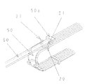
図1は本構成のプリンタの主要部を示した斜視図で、記録ヘッド100は主走査ガイド103によって主走査可能に支持されたヘッドキャリッジ102に搭載されている。
Example 1
FIG. 1 is a perspective view showing a main part of a printer having this configuration. A recording head 100 is mounted on a
ヘッドキャリッジ102は不図示の主走査モータにより図中矢印A方向の往復動し、不図示のプラテン上に搬送された記録用紙Pに画像を形成する。
The
記録ヘッド100にはインク供給チューブ13を介してインクタンク11内のインクが供給される。 The ink in the ink tank 11 is supplied to the recording head 100 via the ink supply tube 13.
インク供給チューブ13はチューブ支持板50とクランプ20によって、チューブ支持板50の本体端50a側はプリンタ天井板70の裏面に固定されている。また同じくヘッドキャリッジ端50bはヘッドキャリッジ102に水平に固定されている。チューブ支持板50は0.1mm程度の厚みで磁性体であるスチール帯板で作られており、適度な剛性と弾性力でインクチューブ13を支持している。
The ink supply tube 13 is fixed to the back surface of the
プリンタ天井板70の裏面には、図1に示したように、クランプ20の爪部21の間に爪部とこすれないように適切な隙間をあけて磁石60が固定されている。
As shown in FIG. 1, a
以上の構成において、図2に示したように、ヘッドキャリッジ102が画像の記録動作によって左端に走査されると、順次チューブ支持板50が磁石60に吸着されて、プリンタ天井板70の裏面に安定的に支持される。
In the above configuration, as shown in FIG. 2, when the
再び図1の位置に向かってヘッドキャリッジ102が走査されると、今度はチューブ支持板50が順次磁石60から引き剥がされながら移動していく。
When the
これらの、吸着、引き剥がしを順次繰り返しつつ、主走査の往復動が繰り返されて、インクチューブは常に安定的に支持さるので、画像品位の乱れのないプリントが可能になる。 The ink tube is always supported in a stable manner by repeating the main scanning reciprocating motion while repeating the suction and peeling in sequence, so that printing without any disturbance in image quality becomes possible.
以上のように、インクチューブを磁力によって安定的に支持するようにしたので、比較的重量の重い可撓性保護管(いわゆるキャタピラ)にインクチューブを支持させる必要もなくなり、軽量化および主走査不可の軽減による主走査駆動手段のコストダウンも達成できる。 As described above, since the ink tube is stably supported by magnetic force, it is not necessary to support the ink tube with a relatively heavy flexible protective tube (so-called caterpillar), and the weight is reduced and main scanning is not possible. It is also possible to reduce the cost of the main scanning driving means by reducing the above.
(実施例2)
図3、図4は第2の実施形態を示すもので、チューブ支持板50のキャリッジ端50bから突出した部分を、プリンタ本体に設けたコロ80で支えられるようにしてある。コロ80の幅は、磁石60と同程度としてあり、クランプ20とぶつからないようにしているのは、言うまでもない。
(Example 2)
3 and 4 show a second embodiment, in which a portion of the
このように、チューブ支持板50の下面を支えることで、図中右端から左端にキャリッジが移動する際のチューブの安定度をさらに向上できる。
Thus, by supporting the lower surface of the
(実施例3)
第1、2の実施形態で配置している磁石60を、ゴム磁石とすることで、チューブ支持板50が磁石に吸着する際に生じる接触音を低くすることができる。
(Example 3)
By using the
(実施例4)
第1、2の実施形態で用いたクランプを磁石で加工し、プリンタ天井板をスチール板としても、同様の効果を得られる。
Example 4
The same effect can be obtained by processing the clamp used in the first and second embodiments with a magnet and using the printer ceiling plate as a steel plate.
11 インクタンク
13 インク供給チューブ
20 クランプ
50 チューブ支持板
60 磁石
100 記録ヘッド
102 ヘッドキャリッジ
11 Ink tank
13 Ink supply tube
20 Clamp
50 Tube support plate
60 magnets
100 recording head
102 Head carriage
Claims (1)
前記記録ヘッドにインクを供給するために前記ヘッドキャリッジに接続された複数のインクチューブと、
前記インクチューブを束ねた状態で保持し、インクチューブの束の位置を規制する磁性材料で形成された可撓性の板状部材と、
前記キャリッジが所定方向に移動する際に近づいてくる前記板状部材を吸着する磁石を有することを特徴とする記録装置。 A head carriage that holds a recording head that performs recording by ejecting ink and scans in a direction perpendicular to the conveyance direction of the recording sheet conveyed on the platen;
A plurality of ink tubes connected to the head carriage for supplying ink to the recording head;
A flexible plate-like member formed of a magnetic material that holds the ink tubes in a bundled state and regulates the position of the bundle of ink tubes;
A recording apparatus comprising: a magnet that attracts the plate-like member approaching when the carriage moves in a predetermined direction.
Priority Applications (1)
| Application Number | Priority Date | Filing Date | Title |
|---|---|---|---|
| JP2005331756A JP2007136785A (en) | 2005-11-16 | 2005-11-16 | Recording device |
Applications Claiming Priority (1)
| Application Number | Priority Date | Filing Date | Title |
|---|---|---|---|
| JP2005331756A JP2007136785A (en) | 2005-11-16 | 2005-11-16 | Recording device |
Publications (1)
| Publication Number | Publication Date |
|---|---|
| JP2007136785A true JP2007136785A (en) | 2007-06-07 |
Family
ID=38200225
Family Applications (1)
| Application Number | Title | Priority Date | Filing Date |
|---|---|---|---|
| JP2005331756A Withdrawn JP2007136785A (en) | 2005-11-16 | 2005-11-16 | Recording device |
Country Status (1)
| Country | Link |
|---|---|
| JP (1) | JP2007136785A (en) |
Cited By (5)
| Publication number | Priority date | Publication date | Assignee | Title |
|---|---|---|---|---|
| CN104080614A (en) * | 2012-01-30 | 2014-10-01 | 精工爱普生株式会社 | inkjet recording device |
| US9162504B2 (en) | 2013-03-29 | 2015-10-20 | Seiko Epson Corporation | Recording apparatus |
| JP2015199264A (en) * | 2014-04-08 | 2015-11-12 | ブラザー工業株式会社 | Liquid discharge device |
| JP2016172455A (en) * | 2016-07-04 | 2016-09-29 | セイコーエプソン株式会社 | Liquid jet device |
| US12441111B2 (en) | 2022-02-01 | 2025-10-14 | Seiko Epson Corporation | Recording device |
-
2005
- 2005-11-16 JP JP2005331756A patent/JP2007136785A/en not_active Withdrawn
Cited By (6)
| Publication number | Priority date | Publication date | Assignee | Title |
|---|---|---|---|---|
| CN104080614A (en) * | 2012-01-30 | 2014-10-01 | 精工爱普生株式会社 | inkjet recording device |
| CN104080614B (en) * | 2012-01-30 | 2016-08-24 | 精工爱普生株式会社 | inkjet recording device |
| US9162504B2 (en) | 2013-03-29 | 2015-10-20 | Seiko Epson Corporation | Recording apparatus |
| JP2015199264A (en) * | 2014-04-08 | 2015-11-12 | ブラザー工業株式会社 | Liquid discharge device |
| JP2016172455A (en) * | 2016-07-04 | 2016-09-29 | セイコーエプソン株式会社 | Liquid jet device |
| US12441111B2 (en) | 2022-02-01 | 2025-10-14 | Seiko Epson Corporation | Recording device |
Similar Documents
| Publication | Publication Date | Title |
|---|---|---|
| CN107264077B (en) | Liquid ejecting apparatus and medium pressing method | |
| JP5282499B2 (en) | Image forming apparatus and sheet conveying apparatus | |
| US8882108B2 (en) | Ink-jet printer | |
| US8075130B2 (en) | Work device and image recording apparatus equipped with the work device | |
| JP5880183B2 (en) | Bearing for conveying roller, conveying apparatus using the bearing, image forming apparatus, and image processing apparatus | |
| JP6860052B2 (en) | Liquid discharge device | |
| JP2007136785A (en) | Recording device | |
| JP5056232B2 (en) | Recording apparatus and liquid ejecting apparatus | |
| JPH10217496A (en) | Ink jet recording device | |
| JP4481699B2 (en) | Printing machine sheet discharge device | |
| US7246962B2 (en) | Exit roller system for an imaging apparatus | |
| JP2012152996A (en) | Tube guide and inkjet recorder | |
| US11059307B2 (en) | Printing apparatus and moving method for support portion | |
| JP2009078415A (en) | Liquid ejector | |
| JP4390508B2 (en) | Carriage transport mechanism, recording head transport apparatus, image forming apparatus, document reading apparatus, and copying machine | |
| JP2005329547A (en) | Carriage scanning mechanism, image input apparatus, and inkjet recording apparatus | |
| JP5731172B2 (en) | Image forming apparatus | |
| JP2009249162A (en) | Transporting device and image recording device | |
| JP2006175860A (en) | Printer with reciprocating carriage and two-stage frame structure | |
| JP2005319721A (en) | Inkjet recording apparatus and recording medium carrying method therefor | |
| JP2010023988A (en) | Ink-jet recording device | |
| JP2010013258A (en) | Ink jet recording device | |
| JP2022139558A (en) | printer | |
| JP4862725B2 (en) | Image recording device | |
| JP4186803B2 (en) | Printing apparatus and printing method |
Legal Events
| Date | Code | Title | Description |
|---|---|---|---|
| A300 | Withdrawal of application because of no request for examination |
Free format text: JAPANESE INTERMEDIATE CODE: A300 Effective date: 20090203 |