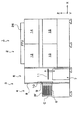
JP2007103956A - Substrate processing equipment - Google Patents

Substrate processing equipment Download PDF

Info

Publication number
JP2007103956A
JP2007103956A JP2006300391A JP2006300391A JP2007103956A JP 2007103956 A JP2007103956 A JP 2007103956A JP 2006300391 A JP2006300391 A JP 2006300391A JP 2006300391 A JP2006300391 A JP 2006300391A JP 2007103956 A JP2007103956 A JP 2007103956A
Authority
JP
Japan
Prior art keywords
wafer
supply nozzle
substrate
pure water
supplied
Prior art date
Legal status (The legal status is an assumption and is not a legal conclusion. Google has not performed a legal analysis and makes no representation as to the accuracy of the status listed.)
Pending
Application number
JP2006300391A
Other languages
Japanese (ja)
Inventor
Takehiko Orii
武彦 折居
Tatsuya Nishida
辰也 西田
Osamu Kuroda
黒田  修
Current Assignee (The listed assignees may be inaccurate. Google has not performed a legal analysis and makes no representation or warranty as to the accuracy of the list.)
Tokyo Electron Ltd
Original Assignee
Tokyo Electron Ltd
Priority date (The priority date is an assumption and is not a legal conclusion. Google has not performed a legal analysis and makes no representation as to the accuracy of the date listed.)
Filing date
Publication date
Application filed by Tokyo Electron Ltd filed Critical Tokyo Electron Ltd
Priority to JP2006300391A priority Critical patent/JP2007103956A/en
Publication of JP2007103956A publication Critical patent/JP2007103956A/en
Pending legal-status Critical Current

Links

Images

Landscapes

  • Weting (AREA)
  • Cleaning Or Drying Semiconductors (AREA)
  • Liquid Crystal (AREA)
  • Cleaning By Liquid Or Steam (AREA)

Abstract

【課題】処理する必要のない面に薬液が飛散することを防止でき、処理のスループットを向上させることができる基板処理装置を提供する。
【解決手段】基板Wを処理する基板処理装置であって、基板Wの周辺部に薬液を供給する薬液供給ノズル61と、基板W上面に近接した位置と基板W上面から離れた位置との間で相対的に移動するトッププレート72を備え、薬液供給ノズル61を移動自在に構成したことを特徴とする。例えば処理中にトッププレート72を基板W上面に近接した位置に移動して、処理する必要のない面を覆うようにすれば、処理する必要のない面に薬液が飛散することを防止することができる。
【選択図】図7
Disclosed is a substrate processing apparatus that can prevent chemicals from splashing on a surface that does not need to be processed and can improve processing throughput.
A substrate processing apparatus for processing a substrate W, comprising: a chemical solution supply nozzle 61 for supplying a chemical solution to a peripheral portion of the substrate W; and a position close to the upper surface of the substrate W and a position away from the upper surface of the substrate W. And a top plate 72 that moves relatively, and the chemical supply nozzle 61 is configured to be movable. For example, when the top plate 72 is moved to a position close to the upper surface of the substrate W during processing so as to cover a surface that does not need to be processed, it is possible to prevent the chemical solution from being scattered on the surface that does not need to be processed. it can.
[Selection] Figure 7

Description

本発明は、例えば半導体ウェハやLCD基板用ガラス等の基板を洗浄処理などする基板処理装置及び基板処理方法に関する。   The present invention relates to a substrate processing apparatus and a substrate processing method for cleaning a substrate such as a semiconductor wafer or glass for an LCD substrate.

半導体デバイスの製造プロセスにおいては、半導体ウェハ(以下、「ウェハ」という。)に銅などの金属膜を積層すると、ウェハの周辺で金属膜が剥離しやすいという問題がある。ウェハの周辺で剥離が起こると、そこから徐々に剥離が進行して、半導体デバイスを形成する領域まで進行する可能性がある。このような現象を防止するために、ウェハ周辺部の金属膜をあらかじめ除去する周辺部除去処理が行われている。図21は、従来の基板処理装置によって周辺部除去処理をする方法の説明図である。保持手段によってウェハWを回転させ、ウェハWの周辺部にノズルなどの供給装置140によって処理液を供給して、金属膜141の隅を斜めに除去する。一方、ウェハWの中央上部から供給装置142によって純水を供給して、処理液が供給されている部分以外に処理液が付着することを防止するとともに、処理液をウェハWの外周に押し流している。   In the manufacturing process of a semiconductor device, when a metal film such as copper is laminated on a semiconductor wafer (hereinafter referred to as “wafer”), there is a problem that the metal film is easily peeled around the wafer. When peeling occurs around the wafer, peeling may gradually progress from there to a region where a semiconductor device is formed. In order to prevent such a phenomenon, peripheral portion removal processing is performed in which the metal film on the peripheral portion of the wafer is removed in advance. FIG. 21 is an explanatory diagram of a method for performing peripheral portion removal processing by a conventional substrate processing apparatus. The wafer W is rotated by the holding means, and the processing liquid is supplied to the peripheral portion of the wafer W by the supply device 140 such as a nozzle, and the corners of the metal film 141 are removed obliquely. On the other hand, pure water is supplied from the center upper portion of the wafer W by the supply device 142 to prevent the processing liquid from adhering to a portion other than the portion to which the processing liquid is supplied, and the processing liquid is pushed to the outer periphery of the wafer W. Yes.

しかしながら、従来の基板処理装置にあっては、処理液をウェハの外周に押し流す遠心力を得るために、相当に高い回転数が必要であった。また、ウェハ全体に純水を供給するので、周辺のみの処理であるにもかかわらず、ウェハ全体の乾燥処理が必要であった。そのため、ウェハ処理のスループットが低下していた。   However, in the conventional substrate processing apparatus, in order to obtain a centrifugal force that pushes the processing liquid to the outer periphery of the wafer, a considerably high rotational speed is required. In addition, since pure water is supplied to the entire wafer, the entire wafer needs to be dried in spite of the peripheral processing alone. As a result, the throughput of wafer processing has been reduced.

従って本発明の目的は、低速回転でも安定した処理が可能であるとともに、処理のスループットを向上させることができる基板処理装置を提供することにある。   Accordingly, an object of the present invention is to provide a substrate processing apparatus capable of performing stable processing even at low speed rotation and improving processing throughput.

上記課題を解決するために、本発明によれば、基板を処理する基板処理装置であって、基板の周辺部に薬液を供給する薬液供給ノズルと、基板上面に近接した位置と基板上面から離れた位置との間で相対的に移動するトッププレートを備え、前記薬液供給ノズルを移動自在に構成したことを特徴とする、基板処理装置が提供される。例えば処理中にトッププレートを基板上面に近接した位置に移動して、処理する必要のない面を覆うようにすれば、処理する必要のない面に薬液が飛散することを防止することができる。   In order to solve the above problems, according to the present invention, there is provided a substrate processing apparatus for processing a substrate, a chemical supply nozzle for supplying a chemical to a peripheral portion of the substrate, a position close to the substrate upper surface, and a position away from the substrate upper surface A substrate processing apparatus is provided, comprising a top plate that moves relative to a position where the chemical solution supply nozzle is movable. For example, if the top plate is moved to a position close to the upper surface of the substrate during processing so as to cover a surface that does not need to be processed, it is possible to prevent the chemical solution from being scattered on the surface that does not need to be processed.

前記トッププレートには、不活性ガスを供給する上面供給路が設けられていても良い。また、前記薬液供給ノズルは、前記薬液供給ノズルから基板に供給された薬液の飛散を防止する遮蔽板に保持されていても良い。また、前記薬液供給ノズルを、基板の中心から離れる方向に傾斜させて指向させても良い。   The top plate may be provided with an upper surface supply path for supplying an inert gas. The chemical solution supply nozzle may be held by a shielding plate that prevents the chemical solution supplied to the substrate from the chemical solution supply nozzle from being scattered. Further, the chemical solution supply nozzle may be oriented so as to be inclined in a direction away from the center of the substrate.

また、前記薬液供給ノズルよりも基板の内側に純水供給ノズルが配置されていても良い。この場合、前記薬液供給ノズルによって供給される薬液は、例えば、前記純水供給ノズルによって供給されて基板の表面を流れる純水の領域内に供給される。また、前記純水供給ノズルは、前記薬液供給ノズルよりも早いタイミングで純水を供給するように制御されても良い。   Further, a pure water supply nozzle may be disposed inside the substrate with respect to the chemical solution supply nozzle. In this case, the chemical solution supplied by the chemical solution supply nozzle is supplied into, for example, an area of pure water supplied by the pure water supply nozzle and flowing on the surface of the substrate. The pure water supply nozzle may be controlled to supply pure water at an earlier timing than the chemical liquid supply nozzle.

また、前記薬液供給ノズルよりも基板の内側に純水供給ノズルが配置され、前記純水供給ノズルよりも基板の内側に不活性ガス供給ノズルが配置されていても良い。この場合、前記薬液供給ノズルによって供給される薬液は、例えば、前記純水供給ノズルによって供給されて基板の表面を流れる純水の領域内に供給され、前記純水供給ノズルによって供給される純水は、例えば、前記不活性ガス供給ノズルによって供給されて基板の表面を流れる不活性ガスの領域内に供給される。また、前記純水供給ノズルは、前記薬液供給ノズルよりも早いタイミングで純水を供給するように制御され、前記不活性ガス供給ノズルは、前記純水供給ノズルよりも早いタイミングで不活性ガスを供給するように制御されても良い。   Further, a pure water supply nozzle may be disposed inside the substrate with respect to the chemical solution supply nozzle, and an inert gas supply nozzle may be disposed within the substrate with respect to the pure water supply nozzle. In this case, the chemical liquid supplied by the chemical liquid supply nozzle is supplied, for example, in an area of pure water supplied by the pure water supply nozzle and flowing on the surface of the substrate, and supplied by the pure water supply nozzle. Is supplied, for example, in the region of the inert gas supplied by the inert gas supply nozzle and flowing on the surface of the substrate. The pure water supply nozzle is controlled to supply pure water at an earlier timing than the chemical solution supply nozzle, and the inert gas supply nozzle supplies an inert gas at an earlier timing than the pure water supply nozzle. It may be controlled to supply.

なお、異なる処理流体を供給する複数の供給手段を基板の周辺部に沿って相対的に移動させて、基板を処理する基板処理装置であって、前記複数の供給手段を、周辺から内側に向かう方向に並べて配置したことを特徴とする、基板処理装置が提供される。この基板処理装置にあっては、内側に配置された供給手段から供給する処理流体によって、外側に配置された供給手段から供給する例えば薬液などの処理流体を、基板の中心から離れる方向に押し流すことができる。また、前記複数の供給手段を、基板の中心と周辺とを結ぶ線上に並べて配置することが好ましい。   A substrate processing apparatus for processing a substrate by relatively moving a plurality of supply means for supplying different processing fluids along the peripheral portion of the substrate, wherein the plurality of supply means are directed from the periphery to the inside. A substrate processing apparatus is provided, which is arranged side by side in a direction. In this substrate processing apparatus, the processing fluid supplied from the supply means arranged outside is pushed away from the center of the substrate by the processing fluid supplied from the supply means arranged inside. Can do. The plurality of supply means are preferably arranged side by side on a line connecting the center and the periphery of the substrate.

前記複数の供給手段のうち、最も外側に配置された供給手段は、基板に対して薬液を供給し、最も内側に配置された供給手段は、基板に対して不活性の処理流体を供給することが好ましい。不活性の処理流体とは、例えばN2ガス等である。また、前記複数の供給手段のうち最も内側に配置された供給手段は、基板に対して純水を供給してもよい。この場合、最も内側に配置された供給手段は基板を処理しないので、基板の中心側の面を処理せずに周辺部に供給された処理液などを押し流すことができる。   Of the plurality of supply means, the supply means arranged on the outermost side supplies a chemical solution to the substrate, and the supply means arranged on the innermost side supplies an inert processing fluid to the substrate. Is preferred. The inert processing fluid is, for example, N2 gas. Moreover, the supply means arranged at the innermost side among the plurality of supply means may supply pure water to the substrate. In this case, since the supply means arranged at the innermost side does not process the substrate, the processing liquid supplied to the peripheral portion can be swept away without processing the surface on the center side of the substrate.

前記複数の供給手段を、基板の中心から離れる方向に傾斜させて指向させることが好ましい。この場合、内側に配置された供給手段から供給した処理流体によって、外側に配置された供給手段から供給した処理流体を基板の中心から離れる方向に効果的に押し流すことができる。   It is preferable that the plurality of supply units are oriented so as to be inclined in a direction away from the center of the substrate. In this case, the processing fluid supplied from the supply means arranged outside can be effectively swept away in the direction away from the center of the substrate by the processing fluid supplied from the supply means arranged inside.

前記複数の供給手段において、外側に配置された供給手段によって供給される処理流体は、内側に配置された供給手段によって供給されて基板の表面を流れる処理流体の領域内に供給されることが好ましい。さらに、前記複数の供給手段において、内側に配置された供給手段は、外側に配置された供給手段よりも早いタイミングで処理流体を供給するように制御されることが好ましい。この場合、内側に配置された供給手段が供給する処理流体によって、外側に配置された供給手段から供給される処理流体が、内側に配置された供給手段が供給する処理流体が流れる面より外側に流れ込むことを防止できる。   In the plurality of supply means, it is preferable that the processing fluid supplied by the supply means arranged outside is supplied into the region of the processing fluid supplied by the supply means arranged inside and flowing on the surface of the substrate. . Further, in the plurality of supply means, it is preferable that the supply means arranged on the inner side is controlled so as to supply the processing fluid at an earlier timing than the supply means arranged on the outer side. In this case, the processing fluid supplied from the supply means arranged outside by the processing fluid supplied from the supply means arranged inside causes the processing fluid supplied from the supply means arranged inside to be outside the surface through which the processing fluid supplied by the supply means arranged inside flows. It can be prevented from flowing in.

前記複数の供給手段を、基板の中心と周辺とを結ぶ線上に沿って移動自在に構成することが好ましい。この場合、例えば処理面の幅を変化させることができる。そして、前記異なる処理流体による基板の処理を基板の周辺からの距離に応じて段階的に行うことが好ましい。   It is preferable that the plurality of supply units be configured to be movable along a line connecting the center and the periphery of the substrate. In this case, for example, the width of the processing surface can be changed. Then, it is preferable that the processing of the substrate with the different processing fluid is performed stepwise according to the distance from the periphery of the substrate.

前記複数の供給手段から基板に供給された処理流体を吸引する吸引手段を備えることが好ましい。また、前記複数の供給手段から基板に供給された処理流体の飛散を防止する遮蔽板を備えることが好ましい。この場合、前記複数の供給手段を、前記遮蔽板に保持することが好ましい。   It is preferable to include a suction unit that sucks the processing fluid supplied to the substrate from the plurality of supply units. Moreover, it is preferable to provide a shielding plate that prevents scattering of the processing fluid supplied to the substrate from the plurality of supply means. In this case, it is preferable to hold the plurality of supply units on the shielding plate.

さらに、前記基板を囲むアウターチャンバーを設け、前記複数の供給手段を、アウターチャンバーの内外に移動自在にしても良い。この場合、前記複数の供給手段を格納する供給手段格納部を、前記アウターチャンバーの外に設けることが好ましい。   Furthermore, an outer chamber surrounding the substrate may be provided, and the plurality of supply means may be movable in and out of the outer chamber. In this case, it is preferable that a supply means storage section for storing the plurality of supply means is provided outside the outer chamber.

さらに、前記トッププレートと基板の間に不活性雰囲気を吐出することが好ましい。また、前記複数の供給手段を受容する凹欠部を前記トッププレートの周辺部に形成しても良い。この場合、例えば処理中に複数の供給手段は凹欠部に受容された状態で供給を行うようにすれば、他の面をすべてトッププレートによって覆うことができる。さらに、前記トッププレートは回転自在に構成されていることが好ましい。   Furthermore, it is preferable to discharge an inert atmosphere between the top plate and the substrate. Moreover, you may form the recessed part which receives the said several supply means in the peripheral part of the said top plate. In this case, for example, if the supply is performed in a state where the plurality of supply means are received in the recesses during the processing, all other surfaces can be covered with the top plate. Furthermore, it is preferable that the top plate is configured to be rotatable.

また、基板の周辺から内側に向かう方向に並べて配置された複数の供給手段を基板の周辺部に沿って相対的に移動させ、前記複数の供給手段から、基板の周辺部にそれぞれ異なる処理流体を供給して基板を処理するにあたり、内側に配置された供給手段から供給した処理流体によって、外側に配置された供給手段から供給した処理流体を基板の中心から離れる方向に押し流すことを特徴とする、基板処理方法が提供される。   Further, a plurality of supply means arranged side by side in the direction from the periphery of the substrate toward the inside are relatively moved along the peripheral portion of the substrate, and different processing fluids are respectively supplied from the plurality of supply means to the peripheral portion of the substrate. When processing the substrate by supplying, the processing fluid supplied from the supply means arranged outside is pushed away from the center of the substrate by the processing fluid supplied from the supply means arranged inside. A substrate processing method is provided.

前記複数の供給手段のうち、最も外側に配置された供給手段は、基板に対して薬液を供給し、最も内側に配置された供給手段は、基板に対して不活性の処理流体を供給することが好ましい。また、前記複数の供給手段のうち、最も内側に配置された供給手段は、基板に対して純水を供給してもよい。   Of the plurality of supply means, the supply means arranged on the outermost side supplies a chemical solution to the substrate, and the supply means arranged on the innermost side supplies an inert processing fluid to the substrate. Is preferred. Moreover, the supply means arranged at the innermost side among the plurality of supply means may supply pure water to the substrate.

前記複数の供給手段において、内側に配置された供給手段は外側に配置された供給手段よりも早いタイミングで処理流体を供給するように制御されることが好ましい。   In the plurality of supply means, the supply means arranged on the inner side is preferably controlled so as to supply the processing fluid at an earlier timing than the supply means arranged on the outer side.

また、前記複数の供給手段を並べた方向に沿って、前記複数の供給手段を移動させることことが好ましい。この場合、処理面の幅を変化させることができる。さらに、前記複数の供給手段を移動させるに際し、前記異なる処理流体による基板の処理を、基板の周辺からの距離に応じて段階的に行うことが好ましい。   Moreover, it is preferable to move the plurality of supply means along a direction in which the plurality of supply means are arranged. In this case, the width of the processing surface can be changed. Further, when moving the plurality of supply means, it is preferable to perform the processing of the substrate with the different processing fluid in a stepwise manner in accordance with the distance from the periphery of the substrate.

本発明の基板処理装置によれば、例えば処理中にトッププレートを基板上面に近接した位置に移動して、処理する必要のない面を覆うようにすれば、処理する必要のない面に薬液が飛散することを防止することができる。
なお、内側に配置された供給手段から供給する処理流体によって、外側に配置された供給手段から供給する例えば薬液などの処理流体を、基板の中心から離れる方向に押し流すことができる。基板の中心側の面を処理せずに周辺部の処理をすることができる。処理面の幅を変化させることができる。処理する必要のない面に処理流体が飛散することを防止することができる。
According to the substrate processing apparatus of the present invention, for example, if the top plate is moved to a position close to the upper surface of the substrate during the processing so as to cover the surface that does not need to be processed, the chemical solution is applied to the surface that does not need to be processed. It is possible to prevent scattering.
Note that the processing fluid supplied from the supply means arranged on the inside can push away the processing fluid such as a chemical solution supplied from the supply means arranged on the outside in the direction away from the center of the substrate. The peripheral portion can be processed without processing the surface on the center side of the substrate. The width of the processing surface can be changed. It is possible to prevent the processing fluid from splashing on a surface that does not need to be processed.

以下、本発明の好ましい実施の形態を、基板の一例としてウェハの周辺部と裏面を洗浄処理するように構成された基板処理装置としての基板処理ユニットに基づいて説明する。ここでいう洗浄処理とは、基板に積層された膜の除去洗浄を含む。図1は、本実施の形態にかかる基板処理ユニット12、13を組み込んだ洗浄処理システム1の平面図である。図2は、その側面図である。この洗浄処理システム1は、ウェハWに洗浄処理及び洗浄処理後の熱的処理を施す洗浄処理部2と、洗浄処理部2に対してウェハWを搬入出する搬入出部3から構成されている。   Hereinafter, a preferred embodiment of the present invention will be described based on a substrate processing unit as a substrate processing apparatus configured to clean a peripheral portion and a back surface of a wafer as an example of a substrate. The cleaning treatment here includes removal and cleaning of the film stacked on the substrate. FIG. 1 is a plan view of a cleaning processing system 1 incorporating substrate processing units 12 and 13 according to the present embodiment. FIG. 2 is a side view thereof. The cleaning processing system 1 includes a cleaning processing unit 2 that performs a cleaning process on the wafer W and a thermal process after the cleaning process, and a loading / unloading unit 3 that loads the wafer W into and out of the cleaning processing unit 2. .

搬入出部3は、複数枚、例えば25枚のウェハWが所定の間隔で略水平に収容可能な容器(キャリアC)を載置するための載置台6が設けられたイン・アウトポート4と、載置台6に載置されたキャリアCと洗浄処理部2との間でウェハの受け渡しを行うウェハ搬送装置7が備えられたウェハ搬送部5と、から構成されている。   The carry-in / out unit 3 includes an in / out port 4 provided with a mounting table 6 on which a plurality of, for example, 25 wafers W, on which containers (carriers C) that can be accommodated substantially horizontally at predetermined intervals, are mounted. The wafer transfer unit 5 is provided with a wafer transfer unit 7 that transfers a wafer between the carrier C mounted on the mounting table 6 and the cleaning processing unit 2.

ウェハWはキャリアCの一側面を通して搬入出され、キャリアCの側面には開閉可能な蓋体が設けられている。また、キャリアCには、ウェハWを所定間隔で保持するための棚板が内壁に設けられており、ウェハWを収容する25個のスロットが形成されている。ウェハWは表面(半導体デバイスを形成する面)が上面(ウェハWを水平に保持した場合に上側となっている面)となっている状態で各スロットに1枚ずつ収容される。   The wafer W is carried in and out through one side surface of the carrier C, and a lid body that can be opened and closed is provided on the side surface of the carrier C. Further, the carrier C is provided with shelf boards for holding the wafers W at predetermined intervals on the inner wall, and 25 slots for accommodating the wafers W are formed. One wafer W is accommodated in each slot in a state where the surface (surface on which the semiconductor device is formed) is the upper surface (the surface that is the upper side when the wafer W is held horizontally).

イン・アウトポート4の載置台6上には、例えば、3個のキャリアCを水平面のY方向に並べて所定位置に載置することができるようになっている。キャリアCは蓋体が設けられた側面をイン・アウトポート4とウェハ搬送部5との境界壁8側に向けて載置される。境界壁8においてキャリアCの載置場所に対応する位置には窓部9が形成されており、窓部9のウェハ搬送部5側には、窓部9をシャッター等により開閉する窓部開閉機構10が設けられている。   On the mounting table 6 of the in / out port 4, for example, three carriers C can be placed in a predetermined position in the Y direction on the horizontal plane. The carrier C is placed with the side surface on which the lid is provided facing toward the boundary wall 8 between the in / out port 4 and the wafer transfer unit 5. A window portion 9 is formed in the boundary wall 8 at a position corresponding to the place where the carrier C is placed, and a window portion opening / closing mechanism that opens and closes the window portion 9 by a shutter or the like on the wafer transfer portion 5 side of the window portion 9. 10 is provided.

この窓部開閉機構10は、キャリアCに設けられた蓋体もまた開閉可能であり、窓部9の開閉と同時にキャリアCの蓋体も開閉する。窓部開閉機構10は、キャリアCが載置台の所定位置に載置されていないときは動作しないように、インターロックを設けることが好ましい。窓部9を開口してキャリアCのウェハ搬入出口とウェハ搬送部5とを連通させると、ウェハ搬送部5に配設されたウエハ搬送装置7のキャリアCへのアクセスが可能となり、ウェハWの搬送を行うことが可能な状態となる。窓部9の上部には図示しないウェハ検出装置が設けられており、キャリアC内に収容されたウェハWの枚数と状態をスロット毎に検出することができるようになっている。このようなウェハ検出装置は、窓部開閉機構10に装着させることも可能である。   The window opening / closing mechanism 10 can also open and close the lid provided on the carrier C, and simultaneously opens and closes the lid of the carrier C. The window opening / closing mechanism 10 is preferably provided with an interlock so that it does not operate when the carrier C is not placed at a predetermined position of the placement table. When the window 9 is opened to allow the wafer loading / unloading port of the carrier C to communicate with the wafer transfer unit 5, it becomes possible to access the carrier C of the wafer transfer device 7 disposed in the wafer transfer unit 5. It is in a state where it can be transported. A wafer detection device (not shown) is provided above the window 9 so that the number and state of the wafers W accommodated in the carrier C can be detected for each slot. Such a wafer detection apparatus can be mounted on the window opening / closing mechanism 10.

ウェハ搬送部5に配設されたウエハ搬送装置7は、Y方向とZ方向に移動可能であり、かつ、X―Y平面内(θ方向)で回転自在に構成されている。また、ウェハ搬送装置7は、ウェハWを把持する取出収納アーム11を有し、この取出収納アーム11はX方向にスライド自在となっている。こうして、ウェハ搬送装置7は、載置台6に載置された全てのキャリアCの任意の高さのスロットにアクセスし、また、洗浄処理部2に配設された上下2台のウェハ受け渡しユニット16、17にアクセスして、イン・アウトポート4側から洗浄処理部2側へ、逆に洗浄処理部2側からイン・アウトポート4側へウェハWを搬送することができるようになっている。   A wafer transfer device 7 disposed in the wafer transfer unit 5 is movable in the Y direction and the Z direction, and is configured to be rotatable in the XY plane (θ direction). Further, the wafer transfer device 7 has an extraction / accommodating arm 11 for gripping the wafer W, and the extraction / accommodating arm 11 is slidable in the X direction. In this way, the wafer transfer device 7 accesses the slots of any height of all the carriers C mounted on the mounting table 6, and the upper and lower two wafer transfer units 16 disposed in the cleaning processing unit 2. , 17, the wafer W can be transferred from the in / out port 4 side to the cleaning processing unit 2 side, and conversely from the cleaning processing unit 2 side to the in / out port 4 side.

洗浄処理部2は、主ウェハ搬送装置18と、2台のウェハ受け渡しユニット16、17と、本実施の形態にかかる2台の基板処理ユニット12、13と、基板洗浄ユニット14、15と、ウェハWを加熱して乾燥させる3台の加熱ユニット19、20、21と、加熱されたウェハWを冷却する冷却ユニット22とを備えている。主ウェハ搬送装置18は、ウェハ受け渡しユニット16、17、基板処理ユニット12、13、基板洗浄ユニット14、15、加熱ユニット19、20、21、冷却ユニット22の全てのユニットにアクセス可能に配設されている。ウェハ受け渡しユニット16、17は、ウェハ搬送部5との間でウェハWの受け渡しを行うためにウェハWを一時的に載置する。   The cleaning processing unit 2 includes a main wafer transfer device 18, two wafer transfer units 16 and 17, two substrate processing units 12 and 13 according to the present embodiment, a substrate cleaning unit 14 and 15, and a wafer Three heating units 19, 20, and 21 for heating and drying W and a cooling unit 22 for cooling the heated wafer W are provided. The main wafer transfer device 18 is disposed so as to be accessible to all of the wafer transfer units 16 and 17, the substrate processing units 12 and 13, the substrate cleaning units 14 and 15, the heating units 19, 20 and 21, and the cooling unit 22. ing. The wafer delivery units 16 and 17 temporarily place the wafer W in order to deliver the wafer W to and from the wafer transfer unit 5.

また、洗浄処理部2は、洗浄処理システム1全体を稼働させるための電源である電装ユニット23と、洗浄処理システム1内に配設された各種装置及び洗浄処理システム1全体の動作制御を行う機械制御ユニット24と、基板処理ユニット12、13及び基板洗浄ユニット14、15に送液する所定の洗浄液を貯蔵する薬液貯蔵ユニット25とが配設されている。電装ユニット23は図示しない主電源と接続される。洗浄処理部2の天井部には、各ユニット及び主ウェハ搬送装置18に、清浄な空気をダウンフローするためのファンフィルターユニット(FFU)26が配設されている。   The cleaning processing unit 2 includes an electrical unit 23 that is a power source for operating the entire cleaning processing system 1, various devices disposed in the cleaning processing system 1, and a machine that controls the operation of the entire cleaning processing system 1. A control unit 24 and a chemical solution storage unit 25 for storing a predetermined cleaning solution to be fed to the substrate processing units 12 and 13 and the substrate cleaning units 14 and 15 are disposed. The electrical unit 23 is connected to a main power source (not shown). A fan filter unit (FFU) 26 for downflowing clean air is disposed on each unit and the main wafer transfer device 18 on the ceiling portion of the cleaning processing unit 2.

電装ユニット23と薬液貯蔵ユニット25と機械制御ユニット24を洗浄処理部2の外側に設置することによって、又は外部に引き出すことによって、この面(Y方向)からウェハ受け渡しユニット16、17、主ウェハ搬送装置18、加熱ユニット19、20、21、冷却ユニット22のメンテナンスを容易に行うことが可能である。   By installing the electrical unit 23, the chemical storage unit 25, and the machine control unit 24 outside the cleaning processing unit 2 or by pulling them out, the wafer transfer units 16, 17 and the main wafer transfer from this surface (Y direction) Maintenance of the apparatus 18, the heating units 19, 20, 21 and the cooling unit 22 can be easily performed.

図3は、ウェハ受け渡しユニット16、17と、ウェハ受け渡しユニット16、17のX方向に隣接する主ウェハ搬送装置18及び加熱ユニット19、20、21、冷却ユニット22の概略配置を示す断面図である。ウェハ受け渡しユニット16、17は上下2段に積み重ねられて配置されており、例えば、下段のウェハ受け渡しユニット17は、イン・アウトポート4側から洗浄処理部2側へ搬送するウェハWを載置するために用い、上段のウェハ受け渡しユニット16は、洗浄処理部2側からイン・アウトポート4側へ搬送するウェハWを載置するために用いることができる。   FIG. 3 is a cross-sectional view showing a schematic arrangement of the wafer transfer units 16 and 17 and the main wafer transfer device 18 and the heating units 19, 20 and 21 and the cooling unit 22 adjacent to each other in the X direction of the wafer transfer units 16 and 17. . The wafer transfer units 16 and 17 are arranged to be stacked in two upper and lower stages. For example, the lower wafer transfer unit 17 places a wafer W to be transferred from the in / out port 4 side to the cleaning processing unit 2 side. Therefore, the upper wafer transfer unit 16 can be used to place the wafer W to be transferred from the cleaning processing unit 2 side to the in / out port 4 side.

ファンフィルターユニット(FFU)26からのダウンフローの一部は、ウェハ受け渡しユニット16、17と、その上部の空間を通ってウェハ搬送部5に向けて流出する構造となっている。これにより、ウェハ搬送部5から洗浄処理部2へのパーティクル等の侵入が防止され、洗浄処理部2の清浄度が保持されるようになっている。   A part of the down flow from the fan filter unit (FFU) 26 is structured to flow out toward the wafer transfer unit 5 through the wafer transfer units 16 and 17 and the space above the wafer transfer units 16 and 17. This prevents particles and the like from entering the cleaning processing unit 2 from the wafer transfer unit 5 and maintains the cleanliness of the cleaning processing unit 2.

主ウェハ搬送装置7は、Z方向に配置された、垂直壁27、28及びこれらの間の側面開口部29を有する筒状保持体30と、その内側に筒状保持体30に沿ってZ方向に昇降自在に設けられたウェハ搬送体31とを有している。筒状保持体30はモータ32の回転駆動力によって回転可能となっており、それに伴ってウェハ搬送体31も一体的に回転されるようになっている。   The main wafer transfer device 7 includes a cylindrical holder 30 having vertical walls 27 and 28 and a side opening 29 between them disposed in the Z direction, and a Z direction along the cylindrical holder 30 inside thereof. And a wafer carrier 31 provided so as to be movable up and down. The cylindrical holder 30 can be rotated by the rotational driving force of the motor 32, and the wafer carrier 31 is also rotated integrally with the cylindrical holder 30.

ウェハ搬送体31は、搬送基台33と、搬送基台33に沿って前後に移動可能な3本の搬送アーム34、35、36とを備えており、搬送アーム34、35、36は、筒状保持体30の側面開口部29を通過可能な大きさを有している。これら搬送アーム34、35、36は、搬送基台33内に内蔵されたモータ及びベルト機構によってそれぞれ独立して進退移動することが可能となっている。ウェハ搬送体31は、モータ37によってベルト38を駆動させることにより昇降するようになっている。なお、符号39は駆動プーリ、40は従動プーリである。   The wafer transfer body 31 includes a transfer base 33 and three transfer arms 34, 35, and 36 that can move back and forth along the transfer base 33. It has a size capable of passing through the side opening 29 of the shape holding body 30. The transport arms 34, 35, and 36 can be moved forward and backward independently by a motor and a belt mechanism built in the transport base 33. The wafer carrier 31 is moved up and down by driving a belt 38 by a motor 37. Reference numeral 39 is a drive pulley, and 40 is a driven pulley.

ウェハWの強制冷却を行う冷却ユニット22の上には、加熱ユニット19、20、21が3台積み重ねられて配設されている。なお、ウェハ受け渡しユニット16、17の上部の空間に冷却ユニット22、加熱ユニット19、20、21を設けることも可能である。この場合には、図1に示される冷却ユニット22、加熱ユニット19、20、21の位置をその他のユーティリティ空間として利用することができる。   On the cooling unit 22 for forcibly cooling the wafer W, three heating units 19, 20, and 21 are stacked and arranged. It is also possible to provide the cooling unit 22 and the heating units 19, 20, 21 in the space above the wafer transfer units 16, 17. In this case, the positions of the cooling unit 22 and the heating units 19, 20, and 21 shown in FIG. 1 can be used as other utility spaces.

基板処理ユニット12、13は、上下2段に配設されている。また、基板処理ユニット12、13は、ウェハW裏面の洗浄と、ウェハW表面の周辺部の除去処理と洗浄(Back−Bevel洗浄処理)をすることができ、同様の構成を有する。そこで、本実施の形態にかかる基板処理ユニット12を例として、その構造について以下に詳細に説明することとする。   The substrate processing units 12 and 13 are arranged in two upper and lower stages. Further, the substrate processing units 12 and 13 can perform cleaning of the back surface of the wafer W and removal processing and cleaning (Back-Bevel cleaning processing) of the peripheral portion of the front surface of the wafer W, and have the same configuration. Therefore, the structure of the substrate processing unit 12 according to the present embodiment will be described in detail below as an example.

図4は、基板処理ユニット12の平面図である。基板処理ユニット12のユニットチャンバー42内には、ウェハWを収納する密閉構造のアウターチャンバー43と、エッジアーム格納部44を備えている。ユニットチャンバー42には開口45が形成され、開口45を図示しない開閉機構によって開閉するユニットチャンバー用メカシャッター46が設けられており、搬送アームによって基板処理ユニット12に対して開口45からウェハWが搬入出される際には、このユニットチャンバー用メカシャッター46が開くようになっている。ユニットチャンバー用メカシャッター46はユニットチャンバー42の内部から開口45を開閉するようになっており、ユニットチャンバー42内が陽圧になったような場合でも、ユニットチャンバー42内部の雰囲気が外部に漏れ出ない。   FIG. 4 is a plan view of the substrate processing unit 12. The unit chamber 42 of the substrate processing unit 12 includes an outer chamber 43 having a sealed structure for storing the wafer W and an edge arm storage portion 44. An opening 45 is formed in the unit chamber 42, and a unit chamber mechanical shutter 46 that opens and closes the opening 45 by an opening / closing mechanism (not shown) is provided. A wafer W is loaded into the substrate processing unit 12 from the opening 45 by a transfer arm. When being taken out, the unit chamber mechanical shutter 46 is opened. The mechanical shutter 46 for the unit chamber opens and closes the opening 45 from the inside of the unit chamber 42. Even when the inside of the unit chamber 42 becomes positive pressure, the atmosphere inside the unit chamber 42 leaks to the outside. Absent.

アウターチャンバー43には開口47が形成され、開口47を図示しないシリンダ駆動機構によって開閉するアウターチャンバー用メカシャッター48が設けられており、例えば搬送アーム34によってアウターチャンバー43に対して開口47からウェハWが搬入出される際には、このアウターチャンバー用メカシャッター48が開くようになっている。アウターチャンバー用メカシャッター48は、ユニットチャンバー用メカシャッター46と共通の開閉機構によって開閉するようにしても良い。アウターチャンバー用メカシャッター48はアウターチャンバー43の内部から開口47を開閉するようになっており、アウターチャンバー43内が陽圧になったような場合でも、アウターチャンバー43内部の雰囲気が外部に漏れ出ない。   An opening 47 is formed in the outer chamber 43, and an outer chamber mechanical shutter 48 that opens and closes the opening 47 by a cylinder drive mechanism (not shown) is provided. For example, the wafer W is opened from the opening 47 to the outer chamber 43 by the transfer arm 34. The outer chamber mechanical shutter 48 is opened when the is carried in and out. The outer chamber mechanical shutter 48 may be opened and closed by an opening / closing mechanism common to the unit chamber mechanical shutter 46. The outer chamber mechanical shutter 48 opens and closes the opening 47 from the inside of the outer chamber 43. Even when the pressure in the outer chamber 43 becomes positive, the atmosphere inside the outer chamber 43 leaks to the outside. Absent.

また、エッジアーム格納部44には開口49が形成され、開口49を図示しない駆動機構によって開閉するエッジアーム格納部用シャッター50が設けられている。エッジアーム格納部44をアウターチャンバー43と雰囲気隔離するときは、このエッジアーム格納部用シャッター50を閉じる。エッジアーム格納部用シャッター50はアウターチャンバー43の内部から開口49を開閉するようになっており、ユニットチャンバー42内が陽圧になったような場合でも、ユニットチャンバー42内部の雰囲気が外部に漏れ出ない。   The edge arm storage portion 44 is provided with an opening 49, and an edge arm storage portion shutter 50 that opens and closes the opening 49 by a driving mechanism (not shown) is provided. When the edge arm storage portion 44 is isolated from the outer chamber 43 in an atmosphere, the edge arm storage portion shutter 50 is closed. The edge arm shutter 50 opens and closes the opening 49 from the inside of the outer chamber 43, so that the atmosphere inside the unit chamber 42 leaks to the outside even when the inside of the unit chamber 42 becomes positive pressure. Does not appear.

エッジアーム格納部44内には、薬液、純水、及び不活性ガスとしてのN2を吐出可能なエッジアーム60が格納されている。エッジアーム60は、アウターチャンバー43内に収納されており、後述のスピンチャック71で保持されたウェハWの周辺部に移動可能である。エッジアーム60は、処理時以外はエッジアーム格納部44にて待避する。エッジアーム60が開口49からアウターチャンバー43内に移動するときは、エッジアーム格納部用シャッター50が開くようになっている。   In the edge arm storage unit 44, an edge arm 60 capable of discharging chemical liquid, pure water, and N2 as an inert gas is stored. The edge arm 60 is housed in the outer chamber 43 and is movable to the peripheral portion of the wafer W held by a spin chuck 71 described later. The edge arm 60 is retracted in the edge arm storage unit 44 except during processing. When the edge arm 60 moves from the opening 49 into the outer chamber 43, the edge arm storage portion shutter 50 is opened.

エッジアーム60は、図5に示すように、ウェハW(金属膜141)に対して薬液を供給する薬液供給ノズル61、不活性の液体としての純水を供給する純水供給ノズル62、不活性のガスとしてのN2ガスを供給するN2ガス供給ノズル63を備えている。薬液供給ノズル61、純水供給ノズル62、N2ガス供給ノズル63は、ウェハWの中心と周辺部とを結ぶ線上に並べて配置されている。即ち、図示の例では、円形状をなすウェハWの半径方向に並べて配置されている。ウェハW表面には、銅などの金属膜141が積層されており、薬液供給ノズル61は、金属膜141を除去する薬液を供給する。薬液供給ノズル61に隣接して、薬液供給ノズル61よりも内側に配置された純水供給ノズル62は、周辺部のリンス処理を施す純水を供給する。純水供給ノズル62に隣接して、純水供給ノズル62よりも内側に配置されたN2ガス供給ノズル63は、周辺部の乾燥処理を施すN2ガスを供給する。   As shown in FIG. 5, the edge arm 60 includes a chemical solution supply nozzle 61 that supplies a chemical solution to the wafer W (metal film 141), a pure water supply nozzle 62 that supplies pure water as an inactive liquid, and an inactive state. N2 gas supply nozzle 63 for supplying N2 gas as the gas is provided. The chemical solution supply nozzle 61, the pure water supply nozzle 62, and the N 2 gas supply nozzle 63 are arranged side by side on a line connecting the center and the peripheral portion of the wafer W. That is, in the illustrated example, the wafers W having a circular shape are arranged side by side in the radial direction. A metal film 141 such as copper is laminated on the surface of the wafer W, and the chemical solution supply nozzle 61 supplies a chemical solution for removing the metal film 141. A pure water supply nozzle 62 disposed adjacent to the chemical liquid supply nozzle 61 and inside the chemical liquid supply nozzle 61 supplies pure water for rinsing the peripheral portion. An N 2 gas supply nozzle 63 disposed adjacent to the pure water supply nozzle 62 and inside the pure water supply nozzle 62 supplies N 2 gas for performing a drying process on the peripheral portion.

薬液供給ノズル61、純水供給ノズル62、N2ガス供給ノズル63は、遮蔽板64に保持されており、薬液供給ノズル61、純水供給ノズル62、N2ガス供給ノズル63からウェハWに供給された薬液、純水及びN2ガスの飛散を遮蔽板64によって防止するようになっている。薬液供給ノズル61、純水供給ノズル62、N2ガス供給ノズル63は、ウェハWの中心から離れる方向に傾斜して指向している。即ち、薬液供給ノズル61、純水供給ノズル62、N2ガス供給ノズル63の先端はウェハWの外周方向に向かっている。また、薬液供給ノズル61よりもウェハWの外周側に、吸引ノズル65が備えられ、薬液供給ノズル61、純水供給ノズル62、N2ガス供給ノズル63からウェハWに供給された薬液、純水、N2ガス及び処理中に発生する雰囲気を吸引するようになっている。   The chemical solution supply nozzle 61, the pure water supply nozzle 62, and the N2 gas supply nozzle 63 are held by the shielding plate 64, and are supplied to the wafer W from the chemical solution supply nozzle 61, the pure water supply nozzle 62, and the N2 gas supply nozzle 63. The shielding plate 64 prevents the chemical liquid, pure water, and N2 gas from scattering. The chemical solution supply nozzle 61, the pure water supply nozzle 62, and the N 2 gas supply nozzle 63 are inclined and directed in a direction away from the center of the wafer W. That is, the tips of the chemical solution supply nozzle 61, the pure water supply nozzle 62, and the N 2 gas supply nozzle 63 are directed toward the outer periphery of the wafer W. Further, a suction nozzle 65 is provided on the outer peripheral side of the wafer W with respect to the chemical solution supply nozzle 61, and the chemical solution, pure water supplied to the wafer W from the chemical solution supply nozzle 61, the pure water supply nozzle 62, and the N 2 gas supply nozzle 63, N2 gas and the atmosphere generated during processing are sucked.

ウェハWに対して薬液供給ノズル61が薬液を供給する時は、薬液の供給を開始する前に、N2ガス供給ノズル63がN2ガスの供給を開始する。この場合、図6に示すように、N2ガス供給ノズル63はN2ガスを領域68の位置に供給する。領域68に供給されたN2ガスはウェハWの表面(金属膜141の表面)に沿って外周方向に向かって扇状に流れ、領域68’ の形状に流れる。一方、薬液供給ノズル61は薬液を領域66の位置に供給し、領域66に供給された薬液はウェハWの表面に沿って外周方向に向かい、扇状の領域66’に流れることとなる。これら領域66、領域66’はいずれも領域68’の範囲内にあり、前述のように薬液供給ノズル61による薬液の供給が開始される前に、N2ガス供給ノズル63がN2ガスの供給を開始することにより、確実に薬液が領域66に供給され、領域68’ の形状に流れるN2ガスによってウェハWの外周方向に押し流されることとなる。このように、薬液供給ノズル61から供給された薬液がウェハWの中心側に流れる心配がない。また、ウェハWに対して純水供給ノズル62によって純水を供給する時は、純水の供給を開始する前に、N2ガス供給ノズル63がN2ガスの供給を開始する。この場合、図6に示すように、N2ガス供給ノズル63はN2ガスを領域68の位置に供給する。領域68に供給されたN2ガスはウェハWの表面に沿って外周方向に向かって扇状に流れ、領域68’の形状に流れる。一方、純水供給ノズル62は純水を領域67の位置に供給し、領域67に供給された純水はウェハWの表面に沿って外周方向に向かい、扇状の領域67’に流れることとなる。これら領域67、領域67’はいずれも領域68’の範囲内にあり、前述のように純水供給ノズル62による純水の供給が開始される前に、N2ガス供給ノズル63がN2ガスの供給を開始することにより、確実に純水が領域67に供給され、領域68’ の形状に流れるN2ガスによってウェハWの外周方向に押し流されることとなる。このように、純水供給ノズル62から供給された純水がウェハWの中心側に流れる心配がない。なお、領域68’の形状に流れるN2ガスによって薬液と純水を確実に押し流すために、N2ガスが供給される領域68は、領域66と領域67より広い面積を有することが好ましい。即ち、図6に示すように、ウェハWの円周方向における領域68’の幅が、領域66’と領域67’よりも確実に広くなるように供給することができる。   When the chemical solution supply nozzle 61 supplies the chemical solution to the wafer W, the N2 gas supply nozzle 63 starts supplying N2 gas before starting the supply of the chemical solution. In this case, the N 2 gas supply nozzle 63 supplies N 2 gas to the position of the region 68 as shown in FIG. The N 2 gas supplied to the region 68 flows in a fan shape toward the outer periphery along the surface of the wafer W (the surface of the metal film 141), and flows in the shape of the region 68 '. On the other hand, the chemical solution supply nozzle 61 supplies the chemical solution to the position of the region 66, and the chemical solution supplied to the region 66 flows in the outer peripheral direction along the surface of the wafer W and flows into the fan-shaped region 66 ′. These regions 66 and 66 ′ are both within the region 68 ′, and the N2 gas supply nozzle 63 starts supplying N2 gas before the supply of the chemical solution by the chemical solution supply nozzle 61 is started as described above. By doing so, the chemical solution is surely supplied to the region 66 and is pushed away in the outer peripheral direction of the wafer W by the N 2 gas flowing in the shape of the region 68 ′. In this way, there is no concern that the chemical liquid supplied from the chemical liquid supply nozzle 61 flows to the center side of the wafer W. When pure water is supplied to the wafer W by the pure water supply nozzle 62, the N2 gas supply nozzle 63 starts to supply N2 gas before starting the supply of pure water. In this case, the N 2 gas supply nozzle 63 supplies N 2 gas to the position of the region 68 as shown in FIG. The N2 gas supplied to the region 68 flows in a fan shape along the surface of the wafer W toward the outer periphery, and flows in the shape of the region 68 '. On the other hand, the pure water supply nozzle 62 supplies pure water to the position of the region 67, and the pure water supplied to the region 67 flows toward the outer periphery along the surface of the wafer W and flows into the fan-shaped region 67 ′. . These regions 67 and 67 ′ are both within the region 68 ′, and before the supply of pure water by the pure water supply nozzle 62 is started as described above, the N2 gas supply nozzle 63 supplies the N2 gas. As a result, the pure water is surely supplied to the region 67 and is swept away in the outer peripheral direction of the wafer W by the N 2 gas flowing in the shape of the region 68 ′. In this way, there is no concern that the pure water supplied from the pure water supply nozzle 62 flows to the center side of the wafer W. Note that the region 68 to which the N2 gas is supplied preferably has a larger area than the regions 66 and 67 in order to surely push the chemical solution and pure water by the N2 gas flowing in the shape of the region 68 ′. That is, as shown in FIG. 6, the width of the region 68 ′ in the circumferential direction of the wafer W can be supplied so as to be surely wider than the regions 66 ′ and 67 ′.

図7に示すように、アウターチャンバー43内には、ウェハWを収納するインナーカップ70と、このインナーカップ70内で、例えばウェハW表面を上面にして、ウェハWを回転自在に保持する保持手段としてのスピンチャック71と、スピンチャック71により保持されたウェハW上面(ウェハW表面)に対して相対的に昇降移動するトッププレート72を備えている。   As shown in FIG. 7, in the outer chamber 43, an inner cup 70 for storing the wafer W, and a holding means for rotatably holding the wafer W in the inner cup 70 with the surface of the wafer W as an upper surface, for example. And a top plate 72 that moves up and down relatively with respect to the upper surface of the wafer W (wafer W surface) held by the spin chuck 71.

スピンチャック71は、ウェハWを保持するチャック本体73と、このチャック本体73の底部に接続された回転筒体74とを備える。チャック本体73内には、スピンチャック71により保持されたウェハW下面(ウェハW裏面)に対して相対的に昇降移動するアンダープレート75が配置されている。   The spin chuck 71 includes a chuck body 73 that holds the wafer W and a rotating cylinder 74 that is connected to the bottom of the chuck body 73. An under plate 75 that moves up and down relative to the lower surface of the wafer W (back surface of the wafer W) held by the spin chuck 71 is disposed in the chuck body 73.

チャック本体73の上部には、ウェハWの裏面の周縁部を支持するための図示しない支持ピンと、ウェハWを周縁部から保持するための保持部材63がそれぞれ複数箇所に装着されている。図示の例では、チャック本体73の周囲において、中心角が120°となるように、3箇所に保持部材80が配置されており、それら3つの保持部材80により、ウェハWを周りから保持できるようになっている。また、図示はしないが、ウェハWの周縁部を同様に中心角が120°となる位置で下面側から支持できるように、3つの支持ピンがチャック本体73に設けられている。回転筒体74の外周面には、ベルト77が巻回されており、ベルト77をモータ78によって周動させることにより、スピンチャック71全体が回転するようになっている。各保持部材80は、スピンチャック71が回転したときの遠心力を利用して、図4に示すように、ウェハWの周縁部を外側から保持するように構成されている。スピンチャック71が静止しているときは、ウェハWの裏面を支持ピンで支持し、スピンチャック71が回転しているときは、ウェハWの周縁部を保持部材80によって保持する。   On the upper portion of the chuck body 73, support pins (not shown) for supporting the peripheral edge of the back surface of the wafer W and holding members 63 for holding the wafer W from the peripheral edge are mounted at a plurality of locations. In the illustrated example, holding members 80 are arranged at three locations around the chuck main body 73 so that the central angle is 120 °, and the three holding members 80 can hold the wafer W from the periphery. It has become. Although not shown, three support pins are provided on the chuck body 73 so that the peripheral edge of the wafer W can be similarly supported from the lower surface side at a position where the central angle is 120 °. A belt 77 is wound around the outer peripheral surface of the rotating cylinder 74, and the entire spin chuck 71 is rotated by rotating the belt 77 by a motor 78. Each holding member 80 is configured to hold the peripheral edge portion of the wafer W from the outside as shown in FIG. 4 using a centrifugal force when the spin chuck 71 rotates. When the spin chuck 71 is stationary, the back surface of the wafer W is supported by the support pins, and when the spin chuck 71 is rotating, the peripheral portion of the wafer W is held by the holding member 80.

ウェハWを保持する3つの保持部材76は、それぞれ図8に示す構成となっている。保持部材76は把持アーム80、押えアーム81、ばね82によって構成されている。把持アーム80及び押えアーム81はいずれも軸83を中心に回転可能であり、かつ、把持アーム80と押えアーム81の間にばね82が介在している。軸83はチャック本体73に固定されている。押えアーム81の下部には重錘84が設けられている。スピンチャック71が回転すると、図9に示すように、重錘84に遠心力が働いて外側へ移動し、把持アーム80の上部が内側に移動するので、ウェハWを周りから保持することができる。このとき、ばね82は発生したエネルギーを吸収するので、ウェハWを周縁から押える力(保持力)が過度に大きくなるのを防ぐことができる。スピンチャック71の回転が高速になると、図10に示すように、重錘84がチャック本体73内のストッパ85に当接し、ばね82が発生したエネルギーを吸収するので、保持力が過度に大きくなるのを防ぐことができる。   Each of the three holding members 76 that hold the wafer W has a configuration shown in FIG. The holding member 76 includes a grip arm 80, a presser arm 81, and a spring 82. The grip arm 80 and the presser arm 81 are both rotatable about the shaft 83, and a spring 82 is interposed between the grip arm 80 and the presser arm 81. The shaft 83 is fixed to the chuck body 73. A weight 84 is provided below the presser arm 81. When the spin chuck 71 rotates, as shown in FIG. 9, centrifugal force acts on the weight 84 to move outward, and the upper portion of the gripping arm 80 moves inward, so that the wafer W can be held from around. . At this time, since the spring 82 absorbs the generated energy, the force (holding force) for pressing the wafer W from the peripheral edge can be prevented from becoming excessively large. When the spin chuck 71 rotates at a high speed, the weight 84 abuts against the stopper 85 in the chuck body 73 and absorbs the energy generated by the spring 82, as shown in FIG. Can be prevented.

アンダープレート75は、チャック本体73内及び回転筒体74内を貫挿するアンダープレートシャフト90上に接続されている。アンダープレートシャフト90は、水平板91の上面に固着されており、この水平板91は、アンダープレートシャフト90と一体的に、エアシリンダー等からなる昇降機構92により鉛直方向に昇降させられる。従って、アンダープレート75は、図7に示すようにチャック本体73内の下方に下降して、スピンチャック71により保持されたウェハW下面から離れて待機している状態(退避位置)と、図18に示すようにチャック本体73内の上方に上昇して、スピンチャック71により保持されたウェハW下面に対して洗浄処理を施している状態(処理位置)とに上下に移動自在である。なお、アンダープレート75を所定高さに固定する一方で、回転筒体74に図示しない昇降機構を接続させて、スピンチャック71全体を鉛直方向に昇降させることにより、アンダープレート75を処理位置と退避位置に上下に移動自在にしても良い。   The under plate 75 is connected to an under plate shaft 90 that is inserted through the chuck body 73 and the rotating cylinder 74. The under plate shaft 90 is fixed to the upper surface of the horizontal plate 91, and the horizontal plate 91 is moved up and down in the vertical direction integrally with the under plate shaft 90 by an elevating mechanism 92 formed of an air cylinder or the like. Therefore, as shown in FIG. 7, the under plate 75 descends downward in the chuck main body 73 and is in a standby state away from the lower surface of the wafer W held by the spin chuck 71 (retracted position). As shown in FIG. 4, the chuck body 73 moves upward and can move up and down to a state (processing position) where the lower surface of the wafer W held by the spin chuck 71 is subjected to a cleaning process. While the under plate 75 is fixed at a predetermined height, an elevator mechanism (not shown) is connected to the rotating cylinder 74 and the entire spin chuck 71 is moved up and down in the vertical direction, whereby the under plate 75 is retracted from the processing position. The position may be freely movable up and down.

トッププレート72は、トッププレート回転軸95の下端に接続されており、水平板96に設置された回転軸モータ97によって回転する。トッププレート回転軸95は、水平板96の下面に回転自在に保持され、この水平板96は、アウターチャンバー上部に固着されたエアシリンダー等からなる回転軸昇降機構98により鉛直方向に昇降する。従って、トッププレート72は、回転軸昇降機構98の稼動により、図7に示すようにスピンチャック71により保持されたウェハW上面から離れて待機している状態(退避位置)と、図17に示すようにスピンチャック71により保持されたウェハW上面に近接した状態(処理位置)とに上下に移動自在である。また、図4に示すように、トッププレート72の直径はウェハWの直径より小さいので、エッジアーム60がウェハWの周辺部を処理できるようになっている。   The top plate 72 is connected to the lower end of the top plate rotating shaft 95 and is rotated by a rotating shaft motor 97 installed on the horizontal plate 96. The top plate rotating shaft 95 is rotatably held on the lower surface of the horizontal plate 96, and the horizontal plate 96 is moved up and down in the vertical direction by a rotating shaft lifting mechanism 98 composed of an air cylinder or the like fixed to the upper portion of the outer chamber. Therefore, as shown in FIG. 7, the top plate 72 is in a standby state (retracted position) away from the upper surface of the wafer W held by the spin chuck 71 as shown in FIG. Thus, it can move up and down to a state (processing position) close to the upper surface of the wafer W held by the spin chuck 71. As shown in FIG. 4, the diameter of the top plate 72 is smaller than the diameter of the wafer W, so that the edge arm 60 can process the peripheral portion of the wafer W.

インナーカップ70は、図7に示す位置に下降して、スピンチャック71をインナーカップ70の上端よりも上方に突出させてウェハWを授受させる状態と、図17に示す位置に上昇して、スピンチャック71及びウェハWを包囲し、ウェハW両面に供給した洗浄薬液や処理流体等が周囲に飛び散ることを防止する状態とに上下に移動自在である。   The inner cup 70 is lowered to the position shown in FIG. 7, and the spin chuck 71 protrudes above the upper end of the inner cup 70 to transfer the wafer W, and the inner cup 70 is raised to the position shown in FIG. It surrounds the chuck 71 and the wafer W, and is movable up and down to a state in which cleaning chemicals and processing fluid supplied to both surfaces of the wafer W are prevented from scattering around.

インナーカップ70を図7に示した位置に下降させてスピンチャック71を対してウェハWを授受させる場合、アンダープレート75を退避位置に位置させ、トッププレート72を退避位置に位置させておく。そうすれば、アンダープレート75とスピンチャック71により保持されるウェハWの位置との間には、十分な隙間が形成される。また、トッププレート72とウェハWの上面との位置との間にも、十分な隙間が形成される。このようにして、スピンチャック71に対するウェハWの授受が円滑に行われるようになっている。   When the inner cup 70 is lowered to the position shown in FIG. 7 and the wafer W is transferred to the spin chuck 71, the under plate 75 is positioned at the retracted position and the top plate 72 is positioned at the retracted position. Then, a sufficient gap is formed between the under plate 75 and the position of the wafer W held by the spin chuck 71. A sufficient gap is also formed between the position of the top plate 72 and the upper surface of the wafer W. In this way, the transfer of the wafer W to the spin chuck 71 is smoothly performed.

図11に示すように、アンダープレート75には、例えば洗浄薬液や純水などの処理液や乾燥ガスを供給する下面供給路100が、アンダープレートシャフト90内を貫通して設けられている。図12に示すように、アンダープレート75の中心及び周辺部4箇所には、洗浄薬液/純水/N2を吐出する下面吐出口101〜105が設けられている。周辺部の下面吐出口101〜104は、ウェハW周辺に向かって傾斜し、中央の下面吐出口105は、ウェハWの中心に上向きに指向している。   As shown in FIG. 11, the under plate 75 is provided with a lower surface supply path 100 for supplying a treatment liquid such as cleaning chemical liquid or pure water and a dry gas, for example, through the under plate shaft 90. As shown in FIG. 12, lower surface discharge ports 101 to 105 for discharging the cleaning chemical solution / pure water / N 2 are provided at the center and four peripheral portions of the under plate 75. The peripheral lower surface discharge ports 101 to 104 are inclined toward the periphery of the wafer W, and the central lower surface discharge port 105 is directed upward toward the center of the wafer W.

図13に示すように、トッププレート72には、例えばN2ガスを供給する上面供給路106が、トッププレート回転軸95内を貫通して設けられている。アウターチャンバー43上部には、トッププレート72上面とアウターチャンバー内部との間にN2ガスを吐出するN2ガス供給手段107が備えられている。   As shown in FIG. 13, the top plate 72 is provided with an upper surface supply path 106 for supplying, for example, N 2 gas, penetrating through the top plate rotation shaft 95. Above the outer chamber 43, an N2 gas supply means 107 for discharging N2 gas is provided between the upper surface of the top plate 72 and the inside of the outer chamber.

図14に示すように、インナーカップ70の底部には、インナーカップ70内の液滴を排液するインナーカップ排出管110が接続されている。インナーカップ排出管110は、アウターチャンバー43の底部に設けられた貫通口111内を上下動自在である。インナーカップ排出管110の下端は、インナーカップミストトラップ112内に挿入されている。このインナーカップミストトラップ112により、インナーカップ70から排液された液滴中から気泡などを除去するようになっている。除去された気泡は、インナーカップミストトラップ112に接続されたインナーカップミストトラップ排気管113により外部に排気される。気泡を除去された液滴は、インナーカップミストトラップ112に接続されたインナーカップ排液回収ライン114により回収される。   As shown in FIG. 14, an inner cup discharge pipe 110 that discharges droplets in the inner cup 70 is connected to the bottom of the inner cup 70. The inner cup discharge pipe 110 is movable up and down in the through-hole 111 provided at the bottom of the outer chamber 43. The lower end of the inner cup discharge pipe 110 is inserted into the inner cup mist trap 112. The inner cup mist trap 112 removes bubbles from the liquid drained from the inner cup 70. The removed bubbles are exhausted to the outside through an inner cup mist trap exhaust pipe 113 connected to the inner cup mist trap 112. The droplets from which the bubbles have been removed are collected by the inner cup drain collection line 114 connected to the inner cup mist trap 112.

アウターチャンバー43の底部には、アウターチャンバー43内の液滴を排液するアウターチャンバー排出管115が接続されている。アウターチャンバー排出管115には、アウターチャンバーミストトラップ116が設けられ、このアウターチャンバーミストトラップ116により排液された液滴中から気泡などを除去するようになっている。除去された気泡は、アウターチャンバーミストトラップ116に接続されたアウターチャンバーミストトラップ排気管117により外部に排気される。気泡を除去された液滴は、アウターチャンバーミストトラップ116に接続されたアウターチャンバー排液回収ライン118により回収される。   An outer chamber discharge pipe 115 that drains liquid droplets in the outer chamber 43 is connected to the bottom of the outer chamber 43. The outer chamber discharge pipe 115 is provided with an outer chamber mist trap 116 for removing bubbles and the like from liquid droplets discharged by the outer chamber mist trap 116. The removed bubbles are exhausted to the outside by an outer chamber mist trap exhaust pipe 117 connected to the outer chamber mist trap 116. The droplets from which the bubbles have been removed are collected by an outer chamber drainage collection line 118 connected to the outer chamber mist trap 116.

インナーカップ70が下降すると、図15に示すように、スピンチャック71及びこれに保持されたウェハWがインナーカップ70の上端よりも上方に突出した状態となる。この場合は、アウターチャンバー43内の液滴は、インナーカップ70の外側を下降し、アウターチャンバー排出管115によって排液されるようになる。一方、図14に示すように、インナーカップ70が上昇すると、インナーカップ70がスピンチャック71及びウェハWを包囲して、ウェハW両面に供給した洗浄液等が周囲に飛び散ることを防止する状態となる。この場合は、インナーカップ70上部がアウターチャンバー43の内壁に近接し、インナーカップ70内の液滴はインナーカップ排出管110によって排液されるようになる。   When the inner cup 70 is lowered, as shown in FIG. 15, the spin chuck 71 and the wafer W held thereon are projected upward from the upper end of the inner cup 70. In this case, the droplet in the outer chamber 43 descends outside the inner cup 70 and is drained by the outer chamber discharge pipe 115. On the other hand, as shown in FIG. 14, when the inner cup 70 is raised, the inner cup 70 surrounds the spin chuck 71 and the wafer W, and the cleaning liquid or the like supplied to both surfaces of the wafer W is prevented from being scattered around. . In this case, the upper part of the inner cup 70 is close to the inner wall of the outer chamber 43, and the liquid droplets in the inner cup 70 are drained by the inner cup discharge pipe 110.

なお、洗浄処理システム1に備えられた基板処理ユニット13も、基板処理ユニット12と同様の構成を有し、ウェハW裏面の洗浄と、ウェハW表面の周辺部除去処理と周辺部の洗浄(Back−Bevel洗浄処理)をすることができる。   The substrate processing unit 13 provided in the cleaning processing system 1 has the same configuration as that of the substrate processing unit 12, and cleans the back surface of the wafer W, removes the peripheral portion of the front surface of the wafer W, and cleans the peripheral portion (Back). -Bevel washing process).

また、洗浄処理システム1に備えられた基板洗浄ユニット14、15は、各種の洗浄液によりウェハW両面を洗浄し、乾燥処理をすることができるように構成されている。   The substrate cleaning units 14 and 15 provided in the cleaning processing system 1 are configured to clean both surfaces of the wafer W with various cleaning liquids and perform a drying process.

さて、この洗浄処理システム1において、先ず図示しない搬送ロボットにより未だ洗浄されていないウェハWを例えば25枚ずつ収納したキャリアCがイン・アウトポート4に載置される。そして、このイン・アウトポート4に載置されたキャリアCから取出収納アーム11によって一枚ずつウェハWが取り出され、取出収納アーム3から主ウェハ搬送装置7にウェハWが受け渡される。そして、搬送アーム34によってウェハWは基板処理ユニット12又は13に適宜搬入され、ウェハW裏面の洗浄と、ウェハW表面の周辺部除去処理と周辺部の洗浄が行われる。又、基板洗浄ユニット14又は15に適宜搬入され、ウェハWに付着しているパーティクルなどの汚染物質が洗浄、除去される。こうして所定の洗浄処理が終了したウェハWは、再び主ウェハ搬送装置7によって基板処理ユニット12、13又は基板洗浄ユニット14、15から適宜搬出され、取出収納アーム11に受け渡されて、再びキャリアCに収納される。   In this cleaning processing system 1, first, a carrier C storing, for example, 25 wafers W each not yet cleaned by a transfer robot (not shown) is placed on the in / out port 4. Then, the wafers W are taken out one by one from the carrier C placed on the in / out port 4 by the take-out / storage arm 11, and the wafers W are transferred from the take-out / storage arm 3 to the main wafer transfer device 7. Then, the wafer W is appropriately carried into the substrate processing unit 12 or 13 by the transfer arm 34, and the rear surface of the wafer W, the peripheral portion removal processing on the front surface of the wafer W, and the peripheral portion are cleaned. Further, contaminants such as particles that are appropriately carried into the substrate cleaning unit 14 or 15 and adhered to the wafer W are cleaned and removed. The wafer W which has been subjected to the predetermined cleaning process is again unloaded from the substrate processing units 12 and 13 or the substrate cleaning units 14 and 15 by the main wafer transfer device 7 again, transferred to the take-out storage arm 11 and again transferred to the carrier C. It is stored in.

ここで、基板処理ユニット12、13について代表して基板処理ユニット12での処理について説明する。図7に示すように、先ず基板処理ユニット12のユニットチャンバー用メカシャッター46が開き、また、アウターチャンバー43のアウターチャンバー用メカシャッター47が開く。そして、ウェハWを保持した例えば搬送アーム34を装置内に進入させる。インナーカップ70は下降してチャック本体73を上方に相対的に突出させる。アンダープレート75は予め下降してチャック本体73内の退避位置に位置している。トッププレート72は予め上昇して退避位置に位置している。また、エッジアーム格納部用シャッター50は閉じている。   Here, the processing in the substrate processing unit 12 will be described as a representative of the substrate processing units 12 and 13. As shown in FIG. 7, first, the unit chamber mechanical shutter 46 of the substrate processing unit 12 is opened, and the outer chamber mechanical shutter 47 of the outer chamber 43 is opened. Then, for example, the transfer arm 34 holding the wafer W is moved into the apparatus. The inner cup 70 is lowered to cause the chuck body 73 to relatively protrude upward. The under plate 75 is lowered in advance and is located at a retracted position in the chuck body 73. The top plate 72 is raised in advance and located at the retracted position. Further, the edge arm storage portion shutter 50 is closed.

主ウェハ搬送装置18は、搬送アーム34を降ろして保持部材76にウェハWを渡し、スピンチャック71は、図示しない支持ピンによって、半導体デバイスが形成されるウェハW表面を上面にしてウェハWを支持する。この場合、アンダープレート75を退避位置に位置させ、スピンチャック71により保持されるウェハWの位置(高さ)から十分に離すので、搬送アーム34は、余裕をもってウェハWをスピンチャック71に渡すことができる。ウェハWをスピンチャック71に受け渡した後、搬送アーム34はアウターチャンバー43及びユニットチャンバー用メカシャッター46の内部から退出し、退出後、基板処理ユニット12のユニットチャンバー用メカシャッター46とアウターチャンバー43のアウターチャンバー用メカシャッター47が閉じられる。   The main wafer transfer device 18 lowers the transfer arm 34 and transfers the wafer W to the holding member 76, and the spin chuck 71 supports the wafer W with a support pin (not shown) with the surface of the wafer W on which the semiconductor device is formed as the upper surface. To do. In this case, since the under plate 75 is positioned at the retracted position and sufficiently separated from the position (height) of the wafer W held by the spin chuck 71, the transfer arm 34 passes the wafer W to the spin chuck 71 with a margin. Can do. After the wafer W is transferred to the spin chuck 71, the transfer arm 34 moves out of the outer chamber 43 and the unit chamber mechanical shutter 46, and after leaving, the unit chamber mechanical shutter 46 and the outer chamber 43 of the substrate processing unit 12 are moved. The outer chamber mechanical shutter 47 is closed.

インナーカップ70が上昇し、チャック本体73とウェハWを囲んだ状態となる。アンダープレート75は、チャック本体73内の処理位置に上昇する。図17に示すように、処理位置に移動したアンダープレート75とスピンチャック71により保持されたウェハW下面(ウェハW裏面)の間には、例えば0.5〜3mm程度の隙間L1が形成される。   The inner cup 70 is raised, and the chuck body 73 and the wafer W are surrounded. The under plate 75 rises to the processing position in the chuck body 73. As shown in FIG. 17, a gap L1 of, for example, about 0.5 to 3 mm is formed between the under plate 75 moved to the processing position and the lower surface of the wafer W (back surface of the wafer W) held by the spin chuck 71. .

次いで、ウェハW裏面の洗浄処理が行われる。アンダープレート75上では、下面供給路100から洗浄薬液を例えば静かに染み出させて隙間L1に洗浄薬液を供給する。狭い隙間L1において、洗浄薬液をウェハW下面の全体に押し広げ、ウェハW下面全体に均一に接触する洗浄薬液の液膜を形成する。隙間L1全体に洗浄薬液の液膜を形成すると、洗浄薬液の供給を停止してウェハW下面を洗浄処理する。隙間L1に洗浄薬液を液盛りして液膜を形成すると表面張力により洗浄薬液の液膜の形状崩れを防ぐことができる。例えば洗浄薬液の液膜の形状が崩れてしまうと、ウェハW下面において洗浄薬液の液膜に非接触の部分が発生したり、又は液膜中に気泡が混合してしまい洗浄不良を起こしてしまうが、このようにアンダープレート75とウェハW下面の間の狭い隙間L1で洗浄薬液を液盛りすることにより、洗浄薬液の液膜の形状を保って洗浄不良を防止することができる。   Next, a cleaning process for the back surface of the wafer W is performed. On the under plate 75, for example, the cleaning chemical solution is gently exuded from the lower surface supply path 100 and supplied to the gap L <b> 1. In the narrow gap L1, the cleaning chemical is spread over the entire lower surface of the wafer W to form a liquid film of the cleaning chemical that uniformly contacts the entire lower surface of the wafer W. When the cleaning chemical liquid film is formed over the entire gap L1, the supply of the cleaning chemical liquid is stopped and the lower surface of the wafer W is cleaned. When the cleaning chemical liquid is deposited in the gap L1 to form a liquid film, it is possible to prevent the liquid film of the cleaning chemical liquid from being deformed by surface tension. For example, if the shape of the cleaning chemical liquid film collapses, a non-contact portion of the cleaning chemical liquid film occurs on the lower surface of the wafer W, or bubbles are mixed in the liquid film, resulting in poor cleaning. However, by depositing the cleaning chemical liquid in the narrow gap L1 between the under plate 75 and the lower surface of the wafer W in this way, it is possible to maintain the shape of the cleaning chemical liquid film and prevent poor cleaning.

この場合、スピンチャック71は、洗浄薬液の液膜の形状が崩れない程度の比較的低速の回転速度(例えば10〜30rpm程度)でウェハWを回転させる。ウェハWの回転により洗浄薬液の液膜内に液流が発生し、この液流により、洗浄薬液の液膜内の淀みを防止するとともに洗浄効率が向上する。また、ウェハWの回転を間欠的に行っても良い。例えば所定時間若しくは所定回転数、ウェハWを回転させた後、スピンチャック71の回転稼動を所定時間停止させてウェハWを静止させ、その後に再びウェハWを回転させる。このようにウェハWの回転と回転停止を繰り返すと、洗浄薬液をウェハW下面全体に容易に拡散させることができる。もちろん、ウェハWを全く回転させずに静止した状態に保って洗浄処理を施すことも可能である。また、液膜を形成した後では新しい洗浄薬液を供給する必要が無くなる。洗浄薬液の液膜の形状が崩れない限り、ウェハW下面全体を、既にアンダープレート75とウェハW下面の間に供給された洗浄薬液により洗浄できるからである。一方、洗浄薬液の液膜の形状が崩れそうになった場合等には、新液を供給して洗浄薬液の液膜の形状を適宜修復する。このように洗浄薬液の消費量を節約する。なお、ウェハWの回転により洗浄薬液の液膜の液滴をアンダープレート75の周縁から滴り落とす一方で、下面供給路100により洗浄薬液を継続的に供給することにより、洗浄薬液の液膜内を常に真新しい洗浄薬液に置換して好適な洗浄薬液処理を実施することも可能である。この場合も、新液をなるべく静かに供給して洗浄薬液の省液化を図ると良い。   In this case, the spin chuck 71 rotates the wafer W at a relatively low rotational speed (for example, about 10 to 30 rpm) such that the shape of the liquid film of the cleaning chemical solution is not broken. As the wafer W rotates, a liquid flow is generated in the liquid film of the cleaning chemical liquid. This liquid flow prevents stagnation in the liquid film of the cleaning chemical liquid and improves the cleaning efficiency. Further, the wafer W may be rotated intermittently. For example, after rotating the wafer W for a predetermined time or a predetermined number of rotations, the rotation operation of the spin chuck 71 is stopped for a predetermined time, the wafer W is stopped, and then the wafer W is rotated again. If the rotation and stop of the wafer W are repeated in this way, the cleaning chemical can be easily diffused over the entire lower surface of the wafer W. Of course, it is also possible to perform the cleaning process while keeping the wafer W stationary without rotating it at all. Further, it is not necessary to supply a new cleaning chemical after the liquid film is formed. This is because the entire lower surface of the wafer W can be cleaned with the cleaning chemical already supplied between the under plate 75 and the lower surface of the wafer W as long as the shape of the liquid film of the cleaning chemical does not collapse. On the other hand, when the shape of the liquid film of the cleaning chemical liquid is about to collapse, a new liquid is supplied to appropriately repair the shape of the liquid film of the cleaning chemical liquid. In this way, consumption of cleaning chemicals is saved. In addition, while the droplet of the liquid film of the cleaning chemical liquid is dropped from the peripheral edge of the under plate 75 by the rotation of the wafer W, the cleaning chemical liquid is continuously supplied through the lower surface supply path 100, thereby allowing the inside of the liquid film of the cleaning chemical liquid to flow. It is also possible to always carry out a suitable cleaning chemical treatment by replacing with a brand new cleaning chemical. In this case as well, it is preferable to supply the new solution as gently as possible to save the cleaning chemical.

一方、隙間L1に洗浄薬液を液盛りして液膜を形成する際に、洗浄薬液をウェハWの裏面の周囲からウェハWの表面(金属膜141の表面)側へ回り込ませて、後述する周辺部除去が行われるウェハW表面の周辺部にまで洗浄薬液を供給する。そして、ウェハW裏面の洗浄処理と同時に、ウェハW表面の周辺部洗浄処理が行われる。   On the other hand, when forming the liquid film by depositing the cleaning chemical liquid in the gap L1, the cleaning chemical liquid is circulated from the periphery of the back surface of the wafer W to the surface of the wafer W (the surface of the metal film 141) to be described later. The cleaning chemical is supplied to the peripheral portion of the surface of the wafer W where the portion removal is performed. Then, simultaneously with the cleaning process on the back surface of the wafer W, the peripheral part cleaning process on the front surface of the wafer W is performed.

その後、スピンチャック71が例えば2000rpmにて5秒間回転する。即ち、ウェハWに液盛りされた洗浄薬液が振り落とされて、インナーカップ排出管110へ排液される。スピンチャック71が高速回転すると、チャック本体73に設けられた3つの保持部材76は、それぞれ図10に示す状態となる。即ち、押えアーム81の下部がチャック本体73の内部に当接する。従って、高速回転時においては、ウェハWが受ける把持力はばね82によって発生するので、ウェハWに過剰な保持力を与えないようになっている。   Thereafter, the spin chuck 71 rotates, for example, at 2000 rpm for 5 seconds. That is, the cleaning chemical liquid accumulated on the wafer W is shaken off and discharged to the inner cup discharge pipe 110. When the spin chuck 71 rotates at a high speed, the three holding members 76 provided on the chuck main body 73 are in the state shown in FIG. That is, the lower part of the presser arm 81 contacts the inside of the chuck body 73. Accordingly, during high-speed rotation, the gripping force received by the wafer W is generated by the spring 82, so that an excessive holding force is not applied to the wafer W.

次に、アンダープレート75とウェハW下面の間に、下面供給路100から例えば10秒間、N2ガスを供給し、ウェハW下部の洗浄薬液雰囲気を排出する。N2ガスの供給によって、ウェハWの裏面から洗浄薬液の液滴を取り除くことができる。   Next, N 2 gas is supplied between the under plate 75 and the lower surface of the wafer W from the lower surface supply path 100 for 10 seconds, for example, and the cleaning chemical liquid atmosphere below the wafer W is discharged. By supplying the N 2 gas, the droplets of the cleaning chemical liquid can be removed from the back surface of the wafer W.

次いで、トッププレート72がウェハW上面に対して近接した位置まで移動する。エッジアーム格納部用シャッター50が開き、エッジアーム60がスピンチャック71で保持されたウェハWの周辺部上方に移動する。エッジアーム60が所定の位置まで移動すると、エッジアーム60に設けられたN2ガス供給ノズル63がN2ガスの供給を開始し、次いで薬液供給ノズル61が薬液の供給を開始する。そして、ウェハWの表面に積層された金属膜141の隅を薬液によって除去する周辺部除去処理を行う。   Next, the top plate 72 moves to a position close to the upper surface of the wafer W. The edge arm storage unit shutter 50 is opened, and the edge arm 60 is moved above the periphery of the wafer W held by the spin chuck 71. When the edge arm 60 moves to a predetermined position, the N 2 gas supply nozzle 63 provided in the edge arm 60 starts supplying N 2 gas, and then the chemical liquid supply nozzle 61 starts supplying chemical liquid. Then, peripheral portion removal processing is performed in which the corners of the metal film 141 laminated on the surface of the wafer W are removed with a chemical solution.

周辺部除去処理中は、スピンチャック71は例えば300rpm程度の回転数で回転する。この場合、先に説明したように、3つの保持部材76はそれぞれ図9に示す状態となるので、ウェハWに対する適度な保持力が発生して、スピンチャック71はウェハWを回転させることができる。   During the peripheral portion removal process, the spin chuck 71 rotates at a rotation speed of about 300 rpm, for example. In this case, as described above, since the three holding members 76 are in the state shown in FIG. 9, an appropriate holding force for the wafer W is generated, and the spin chuck 71 can rotate the wafer W. .

薬液供給ノズル61の先端はウェハWの外周に向かっているので、薬液はウェハWの外側へスムーズに流れ出る。また、薬液供給ノズル61が供給する薬液は、N2ガス供給ノズル63が供給するN2ガスによって、ウェハWの外周方向へ押し流される。N2ガス供給ノズル63の先端はウェハWの外周方向に向かっているので、N2ガス供給ノズル63が供給するN2ガスによって、薬液をウェハWの外側に効果的に押し流すことができる。ウェハWの表面(金属膜141の表面)において、薬液が供給される領域66と流れる領域66’はいずれも領域68’の範囲内にあり、また、薬液供給ノズル61による薬液の供給が開始される前にN2ガス供給ノズル63がN2ガスの供給を開始するので、薬液供給ノズル61から供給された薬液がウェハWの中心側に流れる心配がない。一方、押し流された薬液、N2ガス及び処理中に発生する薬液雰囲気は、ウェハWの周縁において吸引ノズル65によって吸引、排出される。さらに、薬液供給ノズル61とN2ガス供給ノズル63が保持されている遮蔽板64が、薬液がウェハWの内側の面に飛散することを防止する。また、N2ガスによって押し流される薬液は、回収して適宜の処理を施すことにより容易に再利用が可能である。   Since the tip of the chemical solution supply nozzle 61 is directed toward the outer periphery of the wafer W, the chemical solution flows smoothly out of the wafer W. Further, the chemical solution supplied by the chemical solution supply nozzle 61 is pushed away toward the outer periphery of the wafer W by the N2 gas supplied by the N2 gas supply nozzle 63. Since the tip of the N 2 gas supply nozzle 63 is directed toward the outer periphery of the wafer W, the chemical liquid can be effectively pushed out of the wafer W by the N 2 gas supplied from the N 2 gas supply nozzle 63. On the surface of the wafer W (surface of the metal film 141), both the region 66 to which the chemical solution is supplied and the flowing region 66 ′ are within the region 68 ′, and the supply of the chemical solution by the chemical solution supply nozzle 61 is started. Since the N2 gas supply nozzle 63 starts supplying the N2 gas before the start of the cleaning, there is no concern that the chemical liquid supplied from the chemical liquid supply nozzle 61 flows to the center side of the wafer W. On the other hand, the pushed chemical solution, N 2 gas, and the chemical solution atmosphere generated during the processing are sucked and discharged by the suction nozzle 65 at the periphery of the wafer W. Further, the shielding plate 64 holding the chemical solution supply nozzle 61 and the N2 gas supply nozzle 63 prevents the chemical solution from splashing on the inner surface of the wafer W. Moreover, the chemical liquid swept away by the N2 gas can be easily reused by collecting it and performing an appropriate treatment.

周辺部除去処理中は、トッププレート72は図17に示す位置(処理位置)に下降して、上面供給路106からN2ガスを供給する。上面供給路106が供給するN2ガスは、薬液供給ノズル61が供給する薬液及び周辺部除去処理中に発生する薬液雰囲気が、ウェハWの中心側の面に流れ込むことを防止する。こうして、N2ガス供給ノズル63が供給するN2ガスによって、N2ガスが供給される面と流れる面より外側に薬液が流れることを防止して、さらに上面供給路106が供給するN2ガスによって、薬液がウェハWの中心側の面に流れ込むことを防止するので、薬液がウェハWの内側の面に流れ込むことを効果的に防止できる。また、上面供給路106からN2ガスを供給すると、ウェハW表面のウォーターマーク発生を防止する効果がある。   During the peripheral portion removal process, the top plate 72 descends to the position (processing position) shown in FIG. 17 and supplies N 2 gas from the upper surface supply path 106. The N 2 gas supplied by the upper surface supply path 106 prevents the chemical solution supplied by the chemical solution supply nozzle 61 and the chemical solution atmosphere generated during the peripheral portion removal process from flowing into the central surface of the wafer W. Thus, the N2 gas supplied from the N2 gas supply nozzle 63 prevents the chemical liquid from flowing outside the surface to which the N2 gas is supplied and the flowing surface, and the chemical liquid is further supplied by the N2 gas supplied from the upper surface supply path 106. Since it prevents flowing into the center side surface of the wafer W, it is possible to effectively prevent the chemical solution from flowing into the inner surface of the wafer W. Further, supplying N 2 gas from the upper surface supply path 106 has an effect of preventing the generation of watermarks on the surface of the wafer W.

また、周辺部除去処理中は、アウターチャンバー43上部に備えられたN2ガス供給手段107より、トッププレート72の上部にN2ガスを供給し、ダウンフローを形成する。トッププレート72上面とアウターチャンバー43の間の空間はN2ガスによって満たされるので、薬液の液膜から蒸発してトッププレート72の周囲から上昇する薬液雰囲気が、トッププレート72の上部の空間に回り込まない。従って、周辺部除去処理後、アウターチャンバー43内の上部に薬液が残留することを防ぐことができる。   Further, during the peripheral portion removal process, N2 gas is supplied to the upper portion of the top plate 72 from the N2 gas supply means 107 provided at the upper portion of the outer chamber 43 to form a down flow. Since the space between the top surface of the top plate 72 and the outer chamber 43 is filled with N 2 gas, the chemical liquid atmosphere that evaporates from the liquid film of the chemical liquid and rises from the periphery of the top plate 72 does not enter the space above the top plate 72. . Therefore, it is possible to prevent the chemical liquid from remaining in the upper portion of the outer chamber 43 after the peripheral portion removing process.

周辺部除去処理が終了すると、薬液供給ノズル61は薬液の供給を停止する。N2ガス供給ノズル63はN2ガスの供給を続け、次いで純水供給ノズル62が純水の供給を開始する。そして、ウェハWの周辺部に純水を供給して、周辺部リンス処理を行う。純水供給ノズル62の先端はウェハWの外周に向かっているので、純水はウェハWの外側へスムーズに流れ出る。また、純水供給ノズル62が供給する純水は、N2ガス供給ノズル63が供給するN2ガスによって、ウェハWの外周方向へ押し流される。N2ガス供給ノズル63の先端はウェハWの外周方向に向かっているので、N2ガス供給ノズル63が供給するN2ガスによって、純水をウェハWの外側に効果的に押し流すことができる。ウェハWの表面(金属膜141の表面)において、純水が供給される領域66と流れる領域66’はいずれも領域68’の範囲内にあり、また、純水供給ノズル62による純水の供給が開始される前にN2ガス供給ノズル63がN2ガスの供給を開始するので、純水供給ノズル62から供給された純水がウェハWの中心側に流れる心配がない。さらに、押し流された純水、N2ガス及び処理中に発生する水蒸気雰囲気は、ウェハWの周縁において吸引ノズル65によって吸引、排出される。また、純水供給ノズル62とN2ガス供給ノズル63が保持されている遮蔽板64が、純水がウェハWの内側の面に飛散することを防止する。一方、下面供給路100からアンダープレート75とウェハW下面の間に純水を供給して、裏面リンス処理を行う。こうして、ウェハWの周辺部と裏面をリンス処理し、ウェハWから薬液を洗い流す。   When the peripheral portion removal process is completed, the chemical solution supply nozzle 61 stops supplying the chemical solution. The N2 gas supply nozzle 63 continues to supply N2 gas, and then the pure water supply nozzle 62 starts supplying pure water. Then, pure water is supplied to the peripheral portion of the wafer W to perform peripheral portion rinsing processing. Since the tip of the pure water supply nozzle 62 faces the outer periphery of the wafer W, the pure water smoothly flows out of the wafer W. The pure water supplied by the pure water supply nozzle 62 is pushed away toward the outer periphery of the wafer W by the N 2 gas supplied by the N 2 gas supply nozzle 63. Since the tip of the N 2 gas supply nozzle 63 is directed toward the outer periphery of the wafer W, pure water can be effectively pushed out of the wafer W by the N 2 gas supplied by the N 2 gas supply nozzle 63. On the surface of the wafer W (the surface of the metal film 141), the region 66 to which pure water is supplied and the region 66 ′ that flows are both within the region 68 ′, and pure water is supplied by the pure water supply nozzle 62. Since the N2 gas supply nozzle 63 starts supplying the N2 gas before the start of the process, there is no concern that the pure water supplied from the pure water supply nozzle 62 flows to the center side of the wafer W. Further, the pure water that has been swept away, the N 2 gas, and the water vapor atmosphere generated during the processing are sucked and discharged by the suction nozzle 65 at the periphery of the wafer W. Further, the shielding plate 64 holding the pure water supply nozzle 62 and the N2 gas supply nozzle 63 prevents the pure water from scattering on the inner surface of the wafer W. On the other hand, pure water is supplied from the lower surface supply path 100 between the under plate 75 and the lower surface of the wafer W to perform the back surface rinsing process. Thus, the peripheral portion and the back surface of the wafer W are rinsed, and the chemical solution is washed away from the wafer W.

リンス処理中においても、トッププレート72は処理位置に下降して、上面供給路106からN2ガスを供給する。上面供給路106が供給するN2ガスは、純水供給ノズル62が供給する純水及び周辺部リンス処理中に発生する水蒸気雰囲気が、ウェハWの中心側の面に流れ込むことを防止する。こうして、N2ガス供給ノズル63が供給するN2ガスによって、N2ガスが供給される面と流れる面より外側に純水が流れることを防止して、さらに上面供給路106が供給するN2ガスによって、純水がウェハWの中心側の面に流れ込むことを防止するので、純水がウェハWの内側の面に流れ込むことを効果的に防止できる。また、また、上面供給路106からN2ガスを供給すると、ウェハW表面のウォーターマーク発生を防止する効果がある。   Even during the rinsing process, the top plate 72 descends to the processing position and supplies N 2 gas from the upper surface supply path 106. The N 2 gas supplied from the upper surface supply path 106 prevents the pure water supplied from the pure water supply nozzle 62 and the water vapor atmosphere generated during the peripheral rinse process from flowing into the center side surface of the wafer W. Thus, the N2 gas supplied from the N2 gas supply nozzle 63 prevents pure water from flowing outside the surface to which the N2 gas is supplied and the flowing surface. Since water is prevented from flowing into the central surface of the wafer W, pure water can be effectively prevented from flowing into the inner surface of the wafer W. Further, supplying N 2 gas from the upper surface supply path 106 has an effect of preventing the generation of watermarks on the surface of the wafer W.

リンス処理が終了すると、純水供給ノズル62と下面供給路100による純水の供給を停止する。N2ガス供給ノズル63はウェハWの周辺部にN2ガスの供給を続け、周辺部乾燥処理を行う。N2ガス供給ノズル63の先端はウェハWの外周に向かっているので、N2ガスはウェハWの外側に流れやすくなっている。また、吸引ノズル65によって、N2ガスを吸引して排出する。一方、下面供給路100からアンダープレート75とウェハW下面の間にN2ガスを供給して、裏面乾燥処理を行う。こうして、ウェハWの周辺部と裏面を乾燥処理する。周辺部乾燥処理と裏面乾燥処理が終了すると、N2ガス供給ノズル63と下面供給路100によるN2ガスの供給を停止し、トッププレート72がウェハW上面から離れた位置に上昇する。次いで、ウェハWを乾燥処理するときよりも高速(例えば1500rpm程度)に回転させてウェハWをスピン乾燥させる。   When the rinsing process is completed, the supply of pure water through the pure water supply nozzle 62 and the lower surface supply path 100 is stopped. The N2 gas supply nozzle 63 continues to supply N2 gas to the peripheral portion of the wafer W and performs peripheral portion drying processing. Since the tip of the N 2 gas supply nozzle 63 is directed toward the outer periphery of the wafer W, the N 2 gas easily flows to the outside of the wafer W. Further, the N2 gas is sucked and discharged by the suction nozzle 65. On the other hand, N2 gas is supplied from the lower surface supply path 100 between the under plate 75 and the lower surface of the wafer W to perform the back surface drying process. Thus, the peripheral portion and the back surface of the wafer W are dried. When the peripheral portion drying process and the back surface drying process are completed, the supply of N2 gas by the N2 gas supply nozzle 63 and the lower surface supply path 100 is stopped, and the top plate 72 is raised to a position away from the upper surface of the wafer W. Next, the wafer W is spin-dried by rotating at a higher speed (for example, about 1500 rpm) than when the wafer W is dried.

乾燥処理後、エッジアーム60はエッジアーム格納部44内に移動し、エッジアーム格納部用シャッター50が閉じる。次いで、基板処理ユニット12内からウェハWを搬出する。基板処理ユニット12のユニットチャンバー用メカシャッター46が開き、アウターチャンバー43のアウターチャンバー用メカシャッター47が開く。そして、ウェハ搬送装置18が搬送アーム34を装置内に進入させてウェハW下面を保持させる。次いで、搬送アーム34がスピンチャック71の支持ピンからウェハWを離して受け取り、装置内から退出する。この場合、アンダープレート75は退避位置に位置しているので、搬入するときと同様にアンダープレート75とスピンチャック71により保持されるウェハWの位置との間には、十分な隙間が形成されることになり、搬送アーム34は、余裕をもってスピンチャック71からウェハWを受け取ることができる。   After the drying process, the edge arm 60 moves into the edge arm storage portion 44, and the edge arm storage portion shutter 50 is closed. Next, the wafer W is unloaded from the substrate processing unit 12. The unit chamber mechanical shutter 46 of the substrate processing unit 12 is opened, and the outer chamber mechanical shutter 47 of the outer chamber 43 is opened. Then, the wafer transfer apparatus 18 moves the transfer arm 34 into the apparatus and holds the lower surface of the wafer W. Next, the transfer arm 34 receives the wafer W away from the support pins of the spin chuck 71 and leaves the apparatus. In this case, since the under plate 75 is located at the retracted position, a sufficient gap is formed between the under plate 75 and the position of the wafer W held by the spin chuck 71 as in the case of carrying in. As a result, the transfer arm 34 can receive the wafer W from the spin chuck 71 with a margin.

かかる基板処理装置12によれば、周辺部除去処理中、薬液をウェハWの外側に効果的に押し流すことができる。さらに、薬液、純水、薬液雰囲気、水蒸気雰囲気がウェハWの中心側の面に流れ込むことを防止する。周辺部リンス処理中、純水をウェハWの外側に効果的に押し流すことができる。さらに、純水が供給された面を乾燥させることができる。スピンチャック71が高速回転しても、ウェハWに過剰な保持力を与えない。   According to the substrate processing apparatus 12, the chemical solution can be effectively swept out of the wafer W during the peripheral portion removing process. Further, the chemical solution, pure water, chemical solution atmosphere, and water vapor atmosphere are prevented from flowing into the central surface of the wafer W. Pure water can be effectively swept away from the wafer W during the peripheral rinse process. Furthermore, the surface supplied with pure water can be dried. Even if the spin chuck 71 rotates at a high speed, an excessive holding force is not applied to the wafer W.

以上、本発明の好適な実施の形態の一例を示したが、本発明はここで説明した形態に限定されない。例えば図18に示すように、ユニットチャンバー42上部にFFU122を設け、下部に排気機構123を設けても良い。この場合、アウターチャンバー43内の処理液雰囲気が漏出しても、FFU122によって形成されたダウンフローと排気機構によってユニットチャンバー42から排出される。従って処理後のウェハWを搬出させるとき、処理液雰囲気によってウェハWが汚染される心配が少なく、処理液雰囲気をユニットチャンバー42外に漏出させる心配が少ない。   As mentioned above, although an example of the suitable embodiment of the present invention was shown, the present invention is not limited to the form explained here. For example, as shown in FIG. 18, the FFU 122 may be provided on the upper part of the unit chamber 42, and the exhaust mechanism 123 may be provided on the lower part. In this case, even if the processing liquid atmosphere in the outer chamber 43 leaks, it is discharged from the unit chamber 42 by the downflow and exhaust mechanism formed by the FFU 122. Accordingly, when the processed wafer W is unloaded, there is little concern that the wafer W will be contaminated by the processing liquid atmosphere, and there is little concern that the processing liquid atmosphere will leak out of the unit chamber 42.

また、例えば図19に示すように、トッププレート72に凹欠部125を形成しても良い。この場合、処理中にエッジアーム60が凹欠部に受容された状態で周辺部除去処理、周辺部リンス処理及び周辺部乾燥処理を行うようにすれば、薬液又は純水供給中の面以外の面をすべてトッププレート72によって覆うことができる。従って、薬液又は純水が飛散しても、薬液又は純水供給中の面以外の面に、飛散した液滴が付着することを防止できる。   For example, as shown in FIG. 19, a recess 125 may be formed in the top plate 72. In this case, if the peripheral part removal process, the peripheral part rinse process, and the peripheral part drying process are performed in a state where the edge arm 60 is received in the recessed part during the process, the surface other than the surface that is supplying the chemical solution or the pure water is used. All surfaces can be covered by the top plate 72. Therefore, even if the chemical solution or pure water is scattered, it is possible to prevent the scattered droplets from adhering to a surface other than the surface where the chemical solution or pure water is being supplied.

周辺部除去処理中は、N2ガス供給ノズル63からN2ガスを供給せず、純水供給ノズル62から不活性の処理流体として純水を供給しても良い。この場合、例えば図6に示す領域67に供給された純水は、ウェハWの表面(金属膜141の表面)に沿って外周方向に向かって扇状に流れ、領域67’ の形状に流れる。ウェハWの表面(金属膜141の表面)において、薬液が供給される領域66と流れる領域66’はいずれも領域67’の範囲内にあり、また、薬液供給ノズル61による薬液の供給が開始される前に純水供給ノズル62が純水の供給を開始するので、薬液供給ノズル61から供給された薬液がウェハWの中心側に流れる心配がない。さらに、処理位置に下降したトッププレート72の上面供給路106が供給するN2ガスによって、薬液と純水がウェハWの内側の面に流れ込むことを効果的に防止できる。なお、領域67’ の形状に流れる純水によって薬液を確実に押し流すために、純水が供給される領域67は、領域66より広い面積を有することが好ましい。即ち、図6に示すように、ウェハWの円周方向における領域67’の幅が、領域66’よりも確実に広くなるように供給する。また、周辺部リンス処理中において、N2ガス供給ノズル63からN2ガスを供給せず、純水供給ノズル62から処理流体として純水を供給しても良い。この場合も、処理位置に下降したトッププレート72の上面供給路106が供給するN2ガスによって、純水がウェハWの内側の面に流れ込むことを防止できる。また、周辺部除去処理中に、トッププレート72の上面供給路106からN2ガスを供給せず、N2ガス供給ノズル63からN2ガスを、又は純水供給ノズル62から純水を供給しても良い。この場合、N2ガス供給ノズル63から供給されるN2ガス、又は純水供給ノズル62から供給される純水によって、薬液の流れを制御しながら押し流すことで、薬液がウェハWの内側の面に流れ込むことを防止できる。また、周辺部リンス処理中に、トッププレート72の上面供給路106からN2ガスを供給せず、N2ガス供給ノズル63からN2ガスを供給して、純水供給ノズル62から純水を供給しても良い。この場合も、N2ガス供給ノズル63から供給されるN2ガスによって、純水の流れを制御しながら押し流すことで、純水がウェハWの内側の面に流れむことを防止できる。   During the peripheral portion removal process, N2 gas may not be supplied from the N2 gas supply nozzle 63 and pure water may be supplied from the pure water supply nozzle 62 as an inert processing fluid. In this case, for example, the pure water supplied to the region 67 shown in FIG. 6 flows in a fan shape toward the outer peripheral direction along the surface of the wafer W (the surface of the metal film 141), and flows in the shape of the region 67 '. On the surface of the wafer W (surface of the metal film 141), both the region 66 to which the chemical solution is supplied and the flowing region 66 ′ are within the region 67 ′, and supply of the chemical solution by the chemical solution supply nozzle 61 is started. Since the pure water supply nozzle 62 starts supplying pure water before the cleaning, the chemical liquid supplied from the chemical liquid supply nozzle 61 does not have to worry about flowing toward the center of the wafer W. Furthermore, it is possible to effectively prevent the chemical solution and pure water from flowing into the inner surface of the wafer W by the N 2 gas supplied from the upper surface supply path 106 of the top plate 72 lowered to the processing position. Note that the region 67 to which pure water is supplied preferably has a larger area than the region 66 in order to surely push the chemical solution with the pure water flowing in the shape of the region 67 ′. That is, as shown in FIG. 6, the width of the region 67 ′ in the circumferential direction of the wafer W is supplied so as to be surely wider than the region 66 ′. Further, during the peripheral portion rinsing process, pure water may be supplied as a processing fluid from the pure water supply nozzle 62 without supplying the N2 gas from the N2 gas supply nozzle 63. Also in this case, pure water can be prevented from flowing into the inner surface of the wafer W by the N 2 gas supplied by the upper surface supply path 106 of the top plate 72 that has been lowered to the processing position. Further, during the peripheral portion removal process, N2 gas may not be supplied from the upper surface supply path 106 of the top plate 72, but N2 gas may be supplied from the N2 gas supply nozzle 63 or pure water may be supplied from the pure water supply nozzle 62. . In this case, the chemical liquid flows into the inner surface of the wafer W by pushing it away while controlling the flow of the chemical liquid with N2 gas supplied from the N2 gas supply nozzle 63 or pure water supplied from the pure water supply nozzle 62. Can be prevented. Also, during the peripheral portion rinsing process, N2 gas is not supplied from the upper surface supply path 106 of the top plate 72, N2 gas is supplied from the N2 gas supply nozzle 63, and pure water is supplied from the pure water supply nozzle 62. Also good. Also in this case, the pure water can be prevented from flowing to the inner surface of the wafer W by being pushed away while controlling the flow of the pure water by the N2 gas supplied from the N2 gas supply nozzle 63.

エッジアーム60は、N2ガス供給ノズル63を備えず、薬液供給ノズル61、純水供給ノズル62を備えても良い。この場合でも、周辺部除去処理中に薬液供給ノズル61から供給された薬液がウェハWの中心側に流れむことを防止できる。周辺部リンス処理中にトッププレート72の上面供給路106が供給するN2ガスによって、純水がウェハWの内側の面に流れ込むことを防止できる。また、エッジアーム60は、純水供給ノズル62を備えず、薬液供給ノズル61、N2ガス供給ノズル63を備えても良い。   The edge arm 60 may not include the N2 gas supply nozzle 63 but may include the chemical solution supply nozzle 61 and the pure water supply nozzle 62. Even in this case, it is possible to prevent the chemical liquid supplied from the chemical liquid supply nozzle 61 from flowing toward the center of the wafer W during the peripheral portion removal process. The pure water can be prevented from flowing into the inner surface of the wafer W by the N 2 gas supplied from the upper surface supply path 106 of the top plate 72 during the peripheral portion rinsing process. The edge arm 60 may not include the pure water supply nozzle 62 but may include the chemical solution supply nozzle 61 and the N 2 gas supply nozzle 63.

エッジアーム60を、ウェハWの半径方向に移動自在に構成しても良い。即ち、図6に示すようなそれぞれの処理流体の流れる領域の関係を維持しながら、エッジアーム60を移動させても良い。この場合、例えば周辺部の処理面の幅を変化させることができる。また、薬液によるウェハWの処理を、ウェハWの外周からの距離に応じて段階的に行うことができる。従って、例えば図20に示すように、金属膜141がウェハWの外周側ほど薄くなるように除去することができる。このとき、N2ガス又は純水によってウェハWの内側に薬液が流れ込むことを防止するので、エッジアーム60を内側から外周に向かって移動させることが可能である。このように金属膜141の隅を段状にすると、さらにウェハWから金属膜141が剥離しにくくなる。また、例えば図20に示す膜141a、141b、141cのように、デバイス構造上の膜が多層に積層されている場合は、ウェハWの外周からの除去幅が下層の積層膜ほど狭くなるように除去して、金属膜141がウェハWの外周側ほど薄くなるようにすることが望ましい。   The edge arm 60 may be configured to be movable in the radial direction of the wafer W. That is, the edge arm 60 may be moved while maintaining the relationship between the regions through which the respective processing fluids flow as shown in FIG. In this case, for example, the width of the processing surface in the peripheral portion can be changed. Further, the processing of the wafer W with the chemical solution can be performed in stages according to the distance from the outer periphery of the wafer W. Therefore, for example, as shown in FIG. 20, the metal film 141 can be removed so that the outer peripheral side of the wafer W becomes thinner. At this time, since the chemical liquid is prevented from flowing into the wafer W by the N2 gas or pure water, the edge arm 60 can be moved from the inner side toward the outer periphery. When the corners of the metal film 141 are stepped in this way, the metal film 141 is further difficult to peel from the wafer W. Further, for example, when films on the device structure are laminated in multiple layers like films 141a, 141b, and 141c shown in FIG. 20, the removal width from the outer periphery of the wafer W becomes narrower as the lower laminated film. It is desirable to remove the metal film 141 so that the outer peripheral side of the wafer W becomes thinner.

本発明は洗浄液が供給される基板処理装置に限定されず、その他の種々の処理液などを用いて、周辺部除去及び洗浄以外の他の処理を基板に対して施すものであっても良い。また、基板は半導体ウェハに限らず、その他のLCD基板用ガラスやCD基板、プリント基板、セラミック基板などであっても良い。   The present invention is not limited to the substrate processing apparatus to which the cleaning liquid is supplied, and other various processing liquids or the like may be used to perform processing other than peripheral portion removal and cleaning on the substrate. Further, the substrate is not limited to a semiconductor wafer, but may be another glass for an LCD substrate, a CD substrate, a printed substrate, a ceramic substrate, or the like.

洗浄処理システムの平面図である。It is a top view of a washing processing system. 洗浄処理システムの側面図である。It is a side view of a washing processing system. 洗浄処理システムのウェハ受け渡しユニット、主ウェハ搬送装置、加熱ユニット、冷却ユニットの概略配置を示す断面図である。It is sectional drawing which shows schematic arrangement | positioning of the wafer delivery unit of a cleaning processing system, a main wafer conveyance apparatus, a heating unit, and a cooling unit. 本発明の実施の形態にかかる基板処理ユニットの平面図である。It is a top view of the substrate processing unit concerning an embodiment of the invention. エッジアームの説明図である。It is explanatory drawing of an edge arm. 薬液供給ノズル61、純水供給ノズル62、N2ガス供給ノズル63から供給される各処理流体が供給されるウェハW上の面と、供給された処理流体の流れる面の説明図である。It is explanatory drawing of the surface on the wafer W to which each process fluid supplied from the chemical | medical solution supply nozzle 61, the pure water supply nozzle 62, and the N2 gas supply nozzle 63 is supplied, and the surface through which the supplied process fluid flows. 本発明の実施の形態にかかる処理システムの断面図である。It is sectional drawing of the processing system concerning embodiment of this invention. 静止時における保持部材の状態の説明図である。It is explanatory drawing of the state of the holding member at the time of stillness. 中速回転時における保持部材の状態の説明図である。It is explanatory drawing of the state of the holding member at the time of medium speed rotation. 高速回転時における保持部材の状態の説明図である。It is explanatory drawing of the state of the holding member at the time of high speed rotation. アンダープレート及びアンダープレートシャフトの縦断面図である。It is a longitudinal cross-sectional view of an underplate and an underplate shaft. アンダープレートの平面図である。It is a top view of an underplate. アウターチャンバーの上部を拡大して示した縦断面図である。It is the longitudinal cross-sectional view which expanded and showed the upper part of the outer chamber. インナーカップ内の液滴をミストトラップに排出する工程の説明図である。It is explanatory drawing of the process of discharging the droplet in an inner cup to a mist trap. アウターチャンバー内の液滴をミストトラップに排出する工程の説明図である。It is explanatory drawing of the process of discharging the droplet in an outer chamber to a mist trap. ウェハW裏面をパドル洗浄する工程の説明図である。It is explanatory drawing of the process of carrying out the paddle cleaning of the wafer W back surface. ウェハW周辺部を周辺部除去処理する工程の説明図である。It is explanatory drawing of the process of a peripheral part removal process of the wafer W peripheral part. トッププレートの変形例を示す説明図である。It is explanatory drawing which shows the modification of a top plate. 本発明の実施の形態にかかる基板処理ユニットにおいて、FFUと排気機構を設けた場合の説明図である。It is explanatory drawing at the time of providing FFU and an exhaust mechanism in the substrate processing unit concerning embodiment of this invention. 別の実施の形態における、ウェハW周辺部を周辺部除去処理する工程の説明図である。It is explanatory drawing of the process of carrying out the peripheral part removal process of the wafer W in another embodiment. 従来の基板処理装置において、ウェハW周辺部を周辺部除去処理する工程の説明図である。It is explanatory drawing of the process of carrying out the peripheral part removal process of the wafer W periphery in the conventional substrate processing apparatus.

符号の説明Explanation of symbols

C キャリア
W ウェハ
1 洗浄処理システム
2 洗浄処理部
3 搬入出部
4 イン・アウトポート
5 ウェハ搬送部
7 ウェハ搬送装置
12、13 基板処理ユニット
14、15 基板洗浄ユニット
18 主ウェハ搬送装置
34、35、36 搬送アーム
42 ユニットチャンバー
43 アウターチャンバー
44 エッジアーム格納部
49 開口
50 エッジアーム格納部用シャッター
60 エッジアーム
61 薬液供給ノズル
62 純水供給ノズル
63 N2ガス供給ノズル
64 遮蔽板
65 吸引ノズル
70 インナーカップ
71 スピンチャック
72 トッププレート
73 チャック本体
74 回転筒体
75 アンダープレート
76 保持部材
80 把持アーム
81 押えアーム
82 ばね
83 軸
84 重錘
100 下面供給路
106 上面供給路
107 N2ガス供給手段
125 凹欠部
140 供給装置
141 金属膜
142 供給装置
C carrier W wafer 1 cleaning processing system 2 cleaning processing unit 3 carry-in / out unit 4 in / out port 5 wafer transfer unit 7 wafer transfer unit 12, 13 substrate processing unit 14, 15 substrate cleaning unit 18 main wafer transfer unit 34, 35, 36 Transfer Arm 42 Unit Chamber 43 Outer Chamber 44 Edge Arm Storage 49 Open 50 Edge Arm Storage Shutter 60 Edge Arm 61 Chemical Supply Nozzle 62 Pure Water Supply Nozzle 63 N2 Gas Supply Nozzle 64 Shielding Plate 65 Suction Nozzle 70 Inner Cup 71 Spin chuck 72 Top plate 73 Chuck body 74 Rotating cylinder 75 Under plate 76 Holding member 80 Holding arm 81 Presser arm 82 Spring 83 Shaft 84 Weight 100 Lower surface supply path 106 Upper surface supply path 107 N Gas supply means 125 concave portion 140 feeder 141 metal film 142 feeder

Claims (10)

基板を処理する基板処理装置であって、
基板の周辺部に薬液を供給する薬液供給ノズルと、
基板上面に近接した位置と基板上面から離れた位置との間で相対的に移動するトッププレートを備え、
前記薬液供給ノズルを移動自在に構成したことを特徴とする、基板処理装置。
A substrate processing apparatus for processing a substrate,
A chemical supply nozzle for supplying a chemical to the periphery of the substrate;
A top plate that moves relatively between a position close to the substrate upper surface and a position away from the substrate upper surface;
A substrate processing apparatus, wherein the chemical solution supply nozzle is configured to be movable.
前記トッププレートには、不活性ガスを供給する上面供給路が設けられていることを特徴とする、請求項1に記載の基板処理装置。   The substrate processing apparatus according to claim 1, wherein the top plate is provided with an upper surface supply path for supplying an inert gas. 前記薬液供給ノズルは、前記薬液供給ノズルから基板に供給された薬液の飛散を防止する遮蔽板に保持されていることを特徴とする、請求項1または2に記載の基板処理装置。   The substrate processing apparatus according to claim 1, wherein the chemical solution supply nozzle is held by a shielding plate that prevents the chemical solution supplied to the substrate from the chemical solution supply nozzle from being scattered. 前記薬液供給ノズルを、基板の中心から離れる方向に傾斜させて指向させたことを特徴とする、請求項1〜3のいずれかに記載の基板処理装置。   The substrate processing apparatus according to claim 1, wherein the chemical liquid supply nozzle is inclined and directed in a direction away from the center of the substrate. 前記薬液供給ノズルよりも基板の内側に純水供給ノズルが配置されていることを特徴とする、請求項1〜4のいずれかに記載の基板処理装置。   The substrate processing apparatus according to claim 1, wherein a pure water supply nozzle is disposed inside the substrate with respect to the chemical solution supply nozzle. 前記薬液供給ノズルによって供給される薬液は、前記純水供給ノズルによって供給されて基板の表面を流れる純水の領域内に供給されることを特徴とする、請求項5に記載の基板処理装置。   6. The substrate processing apparatus according to claim 5, wherein the chemical solution supplied by the chemical solution supply nozzle is supplied into a region of pure water supplied by the pure water supply nozzle and flowing on the surface of the substrate. 前記純水供給ノズルは、前記薬液供給ノズルよりも早いタイミングで純水を供給するように制御されることを特徴とする、請求項5または6に記載の基板処理装置。   The substrate processing apparatus according to claim 5, wherein the pure water supply nozzle is controlled to supply pure water at an earlier timing than the chemical solution supply nozzle. 前記薬液供給ノズルよりも基板の内側に純水供給ノズルが配置され、前記純水供給ノズルよりも基板の内側に不活性ガス供給ノズルが配置されていることを特徴とする、請求項1〜4のいずれかに記載の基板処理装置。   The pure water supply nozzle is disposed inside the substrate with respect to the chemical liquid supply nozzle, and the inert gas supply nozzle is disposed within the substrate with respect to the pure water supply nozzle. The substrate processing apparatus according to any one of the above. 前記薬液供給ノズルによって供給される薬液は、前記純水供給ノズルによって供給されて基板の表面を流れる純水の領域内に供給され、前記純水供給ノズルによって供給される純水は、前記不活性ガス供給ノズルによって供給されて基板の表面を流れる不活性ガスの領域内に供給されることを特徴とする、請求項8に記載の基板処理装置。   The chemical liquid supplied by the chemical liquid supply nozzle is supplied by the pure water supply nozzle and supplied in the area of pure water flowing on the surface of the substrate, and the pure water supplied by the pure water supply nozzle is inactive. 9. The substrate processing apparatus according to claim 8, wherein the substrate processing apparatus is supplied into a region of an inert gas supplied by a gas supply nozzle and flowing on the surface of the substrate. 前記純水供給ノズルは、前記薬液供給ノズルよりも早いタイミングで純水を供給するように制御され、前記不活性ガス供給ノズルは、前記純水供給ノズルよりも早いタイミングで不活性ガスを供給するように制御されることを特徴とする、請求項8または9に記載の基板処理装置。   The pure water supply nozzle is controlled to supply pure water at an earlier timing than the chemical solution supply nozzle, and the inert gas supply nozzle supplies an inert gas at an earlier timing than the pure water supply nozzle. The substrate processing apparatus according to claim 8, wherein the substrate processing apparatus is controlled as follows.
JP2006300391A 2006-11-06 2006-11-06 Substrate processing equipment Pending JP2007103956A (en)

Priority Applications (1)

Application Number Priority Date Filing Date Title
JP2006300391A JP2007103956A (en) 2006-11-06 2006-11-06 Substrate processing equipment

Applications Claiming Priority (1)

Application Number Priority Date Filing Date Title
JP2006300391A JP2007103956A (en) 2006-11-06 2006-11-06 Substrate processing equipment

Related Parent Applications (1)

Application Number Title Priority Date Filing Date
JP2001234836A Division JP3958539B2 (en) 2001-08-02 2001-08-02 Substrate processing apparatus and substrate processing method

Publications (1)

Publication Number Publication Date
JP2007103956A true JP2007103956A (en) 2007-04-19

Family

ID=38030512

Family Applications (1)

Application Number Title Priority Date Filing Date
JP2006300391A Pending JP2007103956A (en) 2006-11-06 2006-11-06 Substrate processing equipment

Country Status (1)

Country Link
JP (1) JP2007103956A (en)

Cited By (8)

* Cited by examiner, † Cited by third party
Publication number Priority date Publication date Assignee Title
JP2011077244A (en) * 2009-09-30 2011-04-14 Dainippon Screen Mfg Co Ltd Substrate treatment apparatus
JP2013105974A (en) * 2011-11-16 2013-05-30 Tokyo Electron Ltd Cleaning device, peeling system, cleaning method, program, and computer storage medium
JP2015070015A (en) * 2013-09-27 2015-04-13 株式会社Screenホールディングス Substrate processing apparatus and method for processing substrate
KR101512560B1 (en) * 2012-08-31 2015-04-15 가부시키가이샤 스크린 홀딩스 Substrate processing apparatus
JP2017045836A (en) * 2015-08-26 2017-03-02 株式会社Screenホールディングス Substrate processing equipment
JP2018107292A (en) * 2016-12-27 2018-07-05 東京エレクトロン株式会社 Substrate processing method and substrate processing apparatus
US10199231B2 (en) 2013-09-27 2019-02-05 SCREEN Holdings Co., Ltd. Substrate processing apparatus and substrate processing method
KR20230025754A (en) * 2021-08-16 2023-02-23 가부시기가이샤 디스코 Apparatus for coating liquid resin

Citations (16)

* Cited by examiner, † Cited by third party
Publication number Priority date Publication date Assignee Title
JPH0294435A (en) * 1988-09-29 1990-04-05 Nec Corp Etching apparatus
JPH0541144U (en) * 1991-11-07 1993-06-01 ソニー株式会社 Dicing machine
JPH07153731A (en) * 1993-11-30 1995-06-16 Dainippon Screen Mfg Co Ltd Rotating substrate surface washing device
JPH07176509A (en) * 1993-10-29 1995-07-14 Tokyo Electron Ltd Cleaning device and cleaning method
JPH10229062A (en) * 1997-02-14 1998-08-25 Dainippon Screen Mfg Co Ltd Substrate processing system
JPH10303101A (en) * 1997-04-25 1998-11-13 Sony Corp Resist coating equipment
JPH10303169A (en) * 1997-04-30 1998-11-13 Shibaura Eng Works Co Ltd Spin processing device
JPH10314686A (en) * 1997-05-16 1998-12-02 Dainippon Screen Mfg Co Ltd Substrate cleaning method and substrate cleaning apparatus
JPH11102884A (en) * 1997-09-29 1999-04-13 Dainippon Screen Mfg Co Ltd Substrate processing apparatus and peripheral member cleaning method
JPH11329955A (en) * 1998-05-19 1999-11-30 Tokyo Electron Ltd Processing device and processing method
JP2000084503A (en) * 1998-07-13 2000-03-28 Kokusai Electric Co Ltd Method and apparatus for treating fluid to be processed
JP2000133625A (en) * 1998-10-23 2000-05-12 Dainippon Screen Mfg Co Ltd Substrate processor
JP2001053051A (en) * 1999-08-10 2001-02-23 Pre-Tech Co Ltd Device and method for drying and washing substrate
JP2001149843A (en) * 1999-11-25 2001-06-05 Shibaura Mechatronics Corp Spin processing apparatus and method
JP2001156032A (en) * 1999-11-26 2001-06-08 Shimada Phys & Chem Ind Co Ltd Cleaning device and cleaning method
JP2001196295A (en) * 2000-01-17 2001-07-19 Tokyo Electron Ltd Substrate processing equipment

Patent Citations (16)

* Cited by examiner, † Cited by third party
Publication number Priority date Publication date Assignee Title
JPH0294435A (en) * 1988-09-29 1990-04-05 Nec Corp Etching apparatus
JPH0541144U (en) * 1991-11-07 1993-06-01 ソニー株式会社 Dicing machine
JPH07176509A (en) * 1993-10-29 1995-07-14 Tokyo Electron Ltd Cleaning device and cleaning method
JPH07153731A (en) * 1993-11-30 1995-06-16 Dainippon Screen Mfg Co Ltd Rotating substrate surface washing device
JPH10229062A (en) * 1997-02-14 1998-08-25 Dainippon Screen Mfg Co Ltd Substrate processing system
JPH10303101A (en) * 1997-04-25 1998-11-13 Sony Corp Resist coating equipment
JPH10303169A (en) * 1997-04-30 1998-11-13 Shibaura Eng Works Co Ltd Spin processing device
JPH10314686A (en) * 1997-05-16 1998-12-02 Dainippon Screen Mfg Co Ltd Substrate cleaning method and substrate cleaning apparatus
JPH11102884A (en) * 1997-09-29 1999-04-13 Dainippon Screen Mfg Co Ltd Substrate processing apparatus and peripheral member cleaning method
JPH11329955A (en) * 1998-05-19 1999-11-30 Tokyo Electron Ltd Processing device and processing method
JP2000084503A (en) * 1998-07-13 2000-03-28 Kokusai Electric Co Ltd Method and apparatus for treating fluid to be processed
JP2000133625A (en) * 1998-10-23 2000-05-12 Dainippon Screen Mfg Co Ltd Substrate processor
JP2001053051A (en) * 1999-08-10 2001-02-23 Pre-Tech Co Ltd Device and method for drying and washing substrate
JP2001149843A (en) * 1999-11-25 2001-06-05 Shibaura Mechatronics Corp Spin processing apparatus and method
JP2001156032A (en) * 1999-11-26 2001-06-08 Shimada Phys & Chem Ind Co Ltd Cleaning device and cleaning method
JP2001196295A (en) * 2000-01-17 2001-07-19 Tokyo Electron Ltd Substrate processing equipment

Cited By (21)

* Cited by examiner, † Cited by third party
Publication number Priority date Publication date Assignee Title
US9165806B2 (en) 2009-09-30 2015-10-20 SCREEN Holdings Co., Ltd. Substrate treatment apparatus
JP2011077244A (en) * 2009-09-30 2011-04-14 Dainippon Screen Mfg Co Ltd Substrate treatment apparatus
JP2013105974A (en) * 2011-11-16 2013-05-30 Tokyo Electron Ltd Cleaning device, peeling system, cleaning method, program, and computer storage medium
US10707097B2 (en) 2012-08-31 2020-07-07 SCREEN Holdings Co., Ltd. Substrate processing apparatus
US10707096B2 (en) 2012-08-31 2020-07-07 SCREEN Holdings Co., Ltd. Substrate processing apparatus
US9555437B2 (en) 2012-08-31 2017-01-31 SCREEN Holdings Co., Ltd. Substrate processing apparatus
US10734252B2 (en) 2012-08-31 2020-08-04 SCREEN Holdings Co., Ltd. Substrate processing apparatus
KR101512560B1 (en) * 2012-08-31 2015-04-15 가부시키가이샤 스크린 홀딩스 Substrate processing apparatus
US10026627B2 (en) 2012-08-31 2018-07-17 SCREEN Holdings Co., Ltd. Substrate processing apparatus
US10720333B2 (en) 2013-09-27 2020-07-21 SCREEN Holdings Co., Ltd. Substrate processing apparatus and substrate processing method
JP2015070015A (en) * 2013-09-27 2015-04-13 株式会社Screenホールディングス Substrate processing apparatus and method for processing substrate
US10199231B2 (en) 2013-09-27 2019-02-05 SCREEN Holdings Co., Ltd. Substrate processing apparatus and substrate processing method
KR20220010753A (en) * 2013-09-27 2022-01-26 가부시키가이샤 스크린 홀딩스 Substrate processing apparatus and substrate processing method
US11342190B2 (en) 2013-09-27 2022-05-24 SCREEN Holdings Co., Ltd. Substrate processing apparatus and substrate processing method
KR102477452B1 (en) 2013-09-27 2022-12-14 가부시키가이샤 스크린 홀딩스 Substrate processing apparatus and substrate processing method
JP2017045836A (en) * 2015-08-26 2017-03-02 株式会社Screenホールディングス Substrate processing equipment
JP2018107292A (en) * 2016-12-27 2018-07-05 東京エレクトロン株式会社 Substrate processing method and substrate processing apparatus
KR20230025754A (en) * 2021-08-16 2023-02-23 가부시기가이샤 디스코 Apparatus for coating liquid resin
JP2023026854A (en) * 2021-08-16 2023-03-01 株式会社ディスコ Liquid resin coating device
JP7712141B2 (en) 2021-08-16 2025-07-23 株式会社ディスコ Liquid resin coating device
KR102886865B1 (en) 2021-08-16 2025-11-14 가부시기가이샤 디스코 Apparatus for coating liquid resin

Similar Documents

Publication Publication Date Title
JP3958539B2 (en) Substrate processing apparatus and substrate processing method
KR100914764B1 (en) Substrate processing apparatus and substrate processing method
JP4570008B2 (en) Liquid processing apparatus and liquid processing method
US7171973B2 (en) Substrate processing apparatus
US7063094B2 (en) Substrate processing apparatus
JP3837026B2 (en) Substrate cleaning apparatus and substrate cleaning method
JP3958594B2 (en) Substrate processing apparatus and substrate processing method
JP2017034235A (en) Substrate processing device, substrate processing method, and storage medium
KR20100138757A (en) Liquid treatment equipment
JP3984004B2 (en) Substrate processing apparatus and substrate processing method
JP3958572B2 (en) Substrate processing apparatus and substrate processing method
JP2007103956A (en) Substrate processing equipment
JP3892687B2 (en) Substrate processing apparatus and substrate processing method
JP2002110612A (en) Cleaning treatment method and cleaning treatment device
JP2003077808A (en) Substrate processing apparatus and substrate processing method
JP4067076B2 (en) Liquid processing method and liquid processing apparatus
JP4091335B2 (en) Liquid processing apparatus and liquid processing method
JP4777322B2 (en) Cleaning processing method and cleaning processing apparatus
JP2004303836A (en) Substrate processing equipment
JP4339026B2 (en) Substrate processing equipment
JP2003031537A (en) Substrate processing equipment
JP2008124503A (en) Liquid processing equipment
JP2001319919A5 (en)
JP2001319915A (en) Liquid processing system and liquid processing method

Legal Events

Date Code Title Description
A131 Notification of reasons for refusal

Free format text: JAPANESE INTERMEDIATE CODE: A131

Effective date: 20081216

A521 Written amendment

Free format text: JAPANESE INTERMEDIATE CODE: A523

Effective date: 20090210

A131 Notification of reasons for refusal

Effective date: 20090721

Free format text: JAPANESE INTERMEDIATE CODE: A131

A521 Written amendment

Effective date: 20090915

Free format text: JAPANESE INTERMEDIATE CODE: A523

A131 Notification of reasons for refusal

Free format text: JAPANESE INTERMEDIATE CODE: A131

Effective date: 20100223

A02 Decision of refusal

Effective date: 20100629

Free format text: JAPANESE INTERMEDIATE CODE: A02