JP2007094684A - Vending machine - Google Patents
Vending machine Download PDFInfo
- Publication number
- JP2007094684A JP2007094684A JP2005282242A JP2005282242A JP2007094684A JP 2007094684 A JP2007094684 A JP 2007094684A JP 2005282242 A JP2005282242 A JP 2005282242A JP 2005282242 A JP2005282242 A JP 2005282242A JP 2007094684 A JP2007094684 A JP 2007094684A
- Authority
- JP
- Japan
- Prior art keywords
- product
- transport mechanism
- receiving member
- merchandise
- column
- Prior art date
- Legal status (The legal status is an assumption and is not a legal conclusion. Google has not performed a legal analysis and makes no representation as to the accuracy of the status listed.)
- Pending
Links
- 230000007246 mechanism Effects 0.000 claims abstract description 30
- 230000007723 transport mechanism Effects 0.000 claims description 101
- 230000032258 transport Effects 0.000 claims description 37
- 238000005192 partition Methods 0.000 claims description 20
- 238000010438 heat treatment Methods 0.000 claims description 13
- 230000005856 abnormality Effects 0.000 claims description 11
- 238000001816 cooling Methods 0.000 claims description 7
- 238000000638 solvent extraction Methods 0.000 claims 2
- 230000000694 effects Effects 0.000 abstract description 5
- 230000000593 degrading effect Effects 0.000 abstract 1
- 238000010586 diagram Methods 0.000 description 3
- 238000007599 discharging Methods 0.000 description 2
- 238000003780 insertion Methods 0.000 description 2
- 230000037431 insertion Effects 0.000 description 2
- 235000013361 beverage Nutrition 0.000 description 1
- 235000009508 confectionery Nutrition 0.000 description 1
- 235000013365 dairy product Nutrition 0.000 description 1
- 239000011521 glass Substances 0.000 description 1
- 230000001771 impaired effect Effects 0.000 description 1
- 230000007257 malfunction Effects 0.000 description 1
- 238000000034 method Methods 0.000 description 1
- 230000003287 optical effect Effects 0.000 description 1
Images


Classifications
-
- G—PHYSICS
- G07—CHECKING-DEVICES
- G07F—COIN-FREED OR LIKE APPARATUS
- G07F11/00—Coin-freed apparatus for dispensing, or the like, discrete articles
- G07F11/46—Coin-freed apparatus for dispensing, or the like, discrete articles from movable storage containers or supports
- G07F11/58—Coin-freed apparatus for dispensing, or the like, discrete articles from movable storage containers or supports the articles being supported on or by endless belts or like conveyors
Landscapes
- Physics & Mathematics (AREA)
- General Physics & Mathematics (AREA)
- Vending Machines For Individual Products (AREA)
- Control Of Vending Devices And Auxiliary Devices For Vending Devices (AREA)
Abstract
Description
本発明は、缶、ビン、ペットボトル若しくは紙パック等に封入された飲料、カップ等の所定の容器に収容された乳製品、箱入りまたは袋入りの菓子等、多様な形状及び大きさを有する商品を販売可能な自動販売機に関するものである。 The present invention relates to products having various shapes and sizes, such as beverages enclosed in cans, bottles, plastic bottles or paper packs, dairy products stored in predetermined containers such as cups, confections in boxes or bags, etc. It is related with the vending machine which can sell.
従来、この種の自動販売機としては、前面に商品取出口を有する自動販売機本体と、自動販売機本体内に設けられた商品収納庫と、商品収納庫内の幅方向及び上下方向に配列された複数の商品コラムと、商品収納庫内の幅方向及び上下方向に移動自在に設けられた商品搬送機構とを備え、商品搬送機構を所定の待機位置から任意の商品コラムまで移動した後、商品コラムの商品を商品搬送機構によって商品取出口まで搬送するようにしたものが知られている(例えば、特許文献1参照。)。
ところで、前記自動販売機では、自動販売機本体の前面に設けられた外扉の一部が透明に形成され、商品収納庫内を外部から視認可能になっているが、商品収納庫の前方には商品取出口が設けられているため、商品取出口の後方に位置する商品コラムへの視認性が低下し、商品展示効果を損なうという問題点があった。また、前記自動販売機では、商品が選択された後、商品搬送機構が商品コラムまで移動し、商品搬送機構によって商品コラムの商品を商品取出口まで搬送するようにしているため、商品が搬出されるまでの利用者の待ち時間が長くなるという問題点もあった。 By the way, in the vending machine, a part of the outer door provided on the front surface of the vending machine main body is formed to be transparent so that the inside of the product storage is visible from the outside. Since the product outlet is provided, the visibility to the product column located behind the product outlet is lowered, and the product display effect is impaired. In the vending machine, after the product is selected, the product transport mechanism moves to the product column, and the product transport mechanism transports the product in the product column to the product take-out port. There was also a problem that the waiting time of the user until the time was long.
本発明は前記問題点に鑑みてなされたものであり、その目的とするところは、商品取出口によって商品収納庫内への視認性を低下させることのない自動販売機を提供することにある。また、他の目的とするところは、前記目的に加え、商品が搬出されるまでの利用者の待ち時間を短縮することのできる自動販売機を提供することにある。 This invention is made | formed in view of the said problem, The place made into the objective is to provide the vending machine which does not reduce the visibility to the inside of goods storage by a goods outlet. Another object of the present invention is to provide a vending machine capable of reducing the waiting time of the user until the product is carried out in addition to the above object.
本発明は前記目的を達成するために、前面に商品取出口を有する自動販売機本体と、自動販売機本体内に設けられた商品収納庫と、商品収納庫内の幅方向及び上下方向に配列された複数の商品コラムと、商品収納庫内の幅方向及び上下方向に移動自在に設けられた商品搬送機構とを備え、商品搬送機構を所定の待機位置から任意の商品コラムまで移動した後、商品コラムの商品を商品搬送機構によって所定の商品搬送位置まで搬送するようにした自動販売機において、前記商品収納庫の一側方に幅方向に開閉可能に設けられ、商品搬送機構によって前記商品搬送位置まで搬送された商品を受容して商品取出口に搬出する商品受容部材を備え、商品受容部材を、商品搬送機構から商品を受容可能な位置まで開放するように設けるとともに、上下方向に移動する商品搬送機構と接触しない位置まで閉鎖するように設けている。 In order to achieve the above object, the present invention provides a vending machine main body having a product outlet on the front surface, a product storage provided in the vending machine main body, and a width direction and a vertical direction in the product storage A plurality of product columns, and a product transport mechanism provided movably in the width direction and the vertical direction in the product storage, and after moving the product transport mechanism from a predetermined standby position to any product column, In a vending machine that transports products in a product column to a predetermined product transport position by a product transport mechanism, the product column is provided on one side of the product storage box so as to be openable and closable in the width direction. A product receiving member that receives the product transported to the position and takes it out to the product outlet is provided, and the product receiving member is provided so as to open from the product transport mechanism to a position where the product can be received, and It is provided so as to close to a position that is not in contact with the product transfer mechanism to move toward.
これにより、商品収納庫の一側方に設けられた商品受容部材を開放し、商品受容部材が商品搬送機構から商品を受容することにより、商品が商品取出口に搬出されることから、商品取出口を商品収納庫の外部に配置することができ、商品取出口によって商品収納庫内への視認性が低下することがない。この場合、商品受容部材を閉鎖することにより、商品搬送機構を商品受容部材に接触することなく移動させることができる。 As a result, the product receiving member provided on one side of the product storage is opened, and the product receiving member receives the product from the product transport mechanism so that the product is carried out to the product outlet. The exit can be arranged outside the product storage, and the visibility into the product storage is not lowered by the product take-out. In this case, by closing the product receiving member, the product transport mechanism can be moved without contacting the product receiving member.
また、本発明は前記他の目的を達成するために、請求項1記載の自動販売機において、前記商品搬送機構が前記待機位置から商品コラムを経て商品搬送位置に移動するまでの間に開放状態の商品受容部材と接触する場合は、商品搬送機構が商品受容部材との接触位置を通過した後、商品搬送機構が商品搬送位置に移動するまでの間に商品受容部材の開放動作を開始する制御手段を備えている。
According to another aspect of the present invention, there is provided the vending machine according to
これにより、請求項1の作用に加え、商品搬送機構が待機位置から商品コラムを経て商品搬送位置に移動するまでの間に開放状態の商品受容部材と接触する場合は、商品搬送機構が商品受容部材との接触位置を通過した後、商品搬送機構が商品搬送位置に移動するまでの間に商品受容部材の開放動作が開始することから、例えば商品搬送機構が商品搬送位置まで完全に移動してから商品受容部材の開放動作を開始するようにした場合に比べ、商品搬出動作を短時間で行うことができる。 Thus, in addition to the operation of the first aspect, when the merchandise transport mechanism comes into contact with the open merchandise receiving member from the standby position through the merchandise column to the merchandise transport position, the merchandise transport mechanism is Since the opening operation of the product receiving member starts after passing the contact position with the member and before the product transport mechanism moves to the product transport position, for example, the product transport mechanism completely moves to the product transport position. Compared to the case where the opening operation of the product receiving member is started, the product carry-out operation can be performed in a short time.
請求項1の発明によれば、商品取出口を商品収納庫の外部に配置することができるので、商品取出口によって商品収納庫内への視認性を低下させることがなく、商品展示効果の向上を図ることができる。
According to the invention of
また、請求項2の発明によれば、請求項1の効果に加え、商品搬出動作を短時間で行うことができるので、商品が搬出されるまでの利用者の待ち時間を短縮することができ、サービス性の向上を図ることができる。
Further, according to the invention of
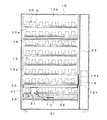
図1乃至図19は本発明の一実施形態を示すもので、図1は自動販売機の正面図、図2はその正面断面図、図3はその側面断面図、図4は商品把持機構の動作を示す平面図、図5は制御系を示すブロック図、図6は商品コラムの配列を示す概略図、図7は制御部の動作を示すフローチャート、図8及び図9は商品搬出動作を示す正面断面図、図10及び図11はその側面断面図、図12乃至図14は他の商品搬出動作を示す正面断面図、図15は異常時の制御部の動作を示すフローチャート、図16は商品コラムの配列を示す概略図、図17乃至図19は異常時の動作を示す側面断面図である。 1 to 19 show an embodiment of the present invention. FIG. 1 is a front view of a vending machine, FIG. 2 is a front sectional view thereof, FIG. 3 is a side sectional view thereof, and FIG. FIG. 5 is a block diagram showing the control system, FIG. 6 is a schematic diagram showing the arrangement of the product columns, FIG. 7 is a flowchart showing the operation of the control unit, and FIGS. 8 and 9 show the product carry-out operation. 10 and 11 are side cross-sectional views thereof, FIGS. 12 to 14 are front cross-sectional views illustrating other commodity carrying-out operations, FIG. 15 is a flowchart illustrating the operation of the control unit in the event of an abnormality, and FIG. FIG. 17 to FIG. 19 are side cross-sectional views showing the operation at the time of abnormality.
この自動販売機は、自動販売機本体10と、自動販売機本体10内に設けられた複数の商品収納装置20と、商品収納装置20の商品Aを搬送する商品搬送機構30と、商品搬出動作を制御する制御部40とを備えている。
The vending machine includes a
自動販売機本体10は前面の幅方向一端側を除く部分を外扉11によって開閉するようになっており、外扉11には透明のガラス窓11aが設けられている。自動販売機本体10の前面の幅方向一端側は補助扉12によって開閉するようになっており、補助扉12の前面には紙幣投入口12a、硬貨投入口12b、金額表示部12c、商品選択操作部12d、硬貨返却口12e及び商品取出口12fが設けられている。自動販売機本体10内の幅方向一端側を除く部分には断熱壁で囲まれた商品収納庫13が設けられ、その一側面には商品取出口12fに商品Aを搬出する商品搬出口13aが設けられている。商品搬出口13aは商品搬送機構30から商品を受容する商品受容部材としてのフラップ14によって開閉するようになっており、商品搬出口13aの側方には商品取出口12fが配置されている。フラップ14は下端を回動自在に支持されるとともに、図示しないモータや歯車からなるフラップ駆動機構15によって回動するようになっている。また、商品収納庫13内は断熱性の仕切板16によって上下方向に仕切られており、仕切板16の仕切位置の上方には図示しないヒータによって加熱される加熱室13bが形成され、仕切板16の下方には図示しない冷却器によって冷却される冷却室13cが形成されている。この場合、仕切板16の前端側には可動仕切板17が設けられ、可動仕切板17は商品搬送機構30と共に上方(加熱室13b側)に移動可能に設けられている。
The vending machine
各商品収納装置20は、前後方向に配列した商品Aを前方に移動させる周知の構成からなり、商品収納庫13内の幅方向及び上下方向にそれぞれ複数ずつ配列されている。各商品収納装置20は、前後方向に延びる装置本体21と、商品Aを前方に移動させるコンベア22と、装置本体21内の幅方向中央を仕切る仕切板23とを備え、装置本体21に商品Aを二列に収納するようになっている。即ち、各商品収納装置20には、商品Aを収納する商品コラム20aが幅方向に二つずつ設けられている。
Each of the
商品搬送機構30は、商品Aを把持する商品把持機構31と、商品把持機構31を商品収納庫13の幅方向に移動させる第1の移動機構32と、第1の移動機構32を上下方向に移動させる幅方向一対の第2の移動機構33とからなり、商品把持機構31は各商品収納装置20の前方を移動するようになっている。商品把持機構31は、幅方向に間隔をおいて設けられた一対の把持部31aを背面側に有し、各把持部31aを図示しない駆動機構によって前後方向及び幅方向にそれぞれ移動させるように構成されている。即ち、商品把持機構31は、図4(a) に示すように各把持部31aを後方に向かって移動して商品Aの両側に位置させた後、図4(b) に示すように各把持部31aを幅方向内側に向かって移動して商品Aを各把持部31aにより把持し、図4(c) に示すように各把持部31aを前方に向かって移動することにより、商品Aを商品コラム20aから取出すようになっている。第1の移動機構32は商品収納庫13内の幅方向に延びるように設けられ、商品把持機構31の上端を幅方向に移動自在に支持している。第2の移動機構33は商品収納庫13の幅方向両側にそれぞれ上下方向に延びるように設けられ、第1の移動機構32の両端をそれぞれ上下方向に移動自在に支持している。即ち、商品搬送機構30は、所定の待機位置(商品収納庫13の幅方向中央下部)から任意の商品コラム20aまで移動し、商品把持機構31によって商品コラム20aから商品Aを取出した後、所定の商品搬送位置(フラップ14の上方)まで移動し、商品Aをフラップ14に放出した後、前記待機位置に戻るようになっている。その際、商品搬送機構30の幅方向及び上下方向位置は、光センサまたはモータのパルスセンサからなる位置検知手段(図示せず)によって検知されるようになっている。尚、フラップ14が開放された状態では、上下方向に移動する第1の移動機構32がフラップ14に接触するため、フラップ14を閉鎖しておくことにより第1の移動機構32とフラップ14が接触しないようになっている。
The
制御部40はマイクロコンピュータによって構成され、商品選択操作部12d、フラップ駆動機構15、商品搬送機構30の商品把持機構31、第1の移動機構32及び第2の移動機構33に接続されている。また、制御部40には記憶部41が接続され、記憶部41には各商品コラム20aに関する情報が記憶されている。即ち、図6に示すように各商品コラム20aには図中左上から順に「1」から「64」までの識別番号が付与されており、記憶部41には各商品コラム20aの識別番号に対応する位置情報(幅方向及び上下方向の位置)が記憶されている。また、記憶部41には、商品搬送機構30が商品コラム20aまで移動した後にフラップ14の開放動作を開始させる場合の商品コラム20a、即ち商品搬送機構30が移動中に開放状態のフラップ14に接触しない位置にある商品コラム20aの番号が記憶されている。本実施形態の場合、図6の一点鎖線で囲まれた上から5段目までの商品コラム20aが対象となり、これらの番号「1」から「40」が記憶部41に記憶されている。また、記憶部41には、商品搬送機構30が商品コラム20aまで移動した後にフラップ14の開放動作を開始させる場合の商品コラム20aの番号を任意に設定可能な設定手段としての設定操作部42が接続されている。
The
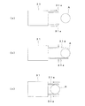
次に、前記制御部40の動作を図7のフローチャートを参照して説明する。まず、商品選択操作部12dによって商品の選択が行われると(S1)、記憶部41から選択商品の商品コラム20aに関する情報を読み取り(S2)、商品搬送機構30を商品コラム20aの位置情報に基づいて商品コラム20aまで移動する(S3)。次に、商品把持機構31による商品取出動作を開始するとともに(S4)、その商品コラム20aが、商品搬送機構30を商品搬送位置まで移動させる間に開放状態のフラップ14に接触する位置にある商品コラム20aに該当しない場合(S5)、即ち商品コラム20aの番号が「1」から「40」である場合には、フラップ14の開放動作を開始し(S6)、商品取出動作が完了した後(S7)、商品搬送機構30を商品搬送位置に向かって幅方向及び上下方向に同時に移動する(S8)。例えば、番号「27」の商品コラム20aの場合、図8に示すように商品搬送機構30が待機位置から商品コラム20aに移動した後、フラップ14の開放動作が開始し、図9に示すように商品搬送機構30がフラップ14へ移動する。
Next, the operation of the
また、前記ステップS5において、商品コラム20aが、商品搬送機構30を商品搬送位置まで移動させる間に開放状態のフラップ14に接触する位置にある商品コラム20aに該当する場合、即ち商品コラム20aの識別番号が「1」から「40」以外の番号である場合には、商品取出動作が完了した後(S9)、商品搬送機構30を上方の所定位置(商品搬送位置と同一の高さ位置)まで移動する(S10)。この後、フラップ14の開放動作を開始し(S11)、商品搬送機構30を幅方向に移動してフラップ14の商品搬送位置へ移動する(S12)。例えば、番号「58」の商品コラム20aの場合、図12に示すように商品搬送機構30が待機位置から商品コラム20に移動し、図13に示すように商品搬送機構30が上方に移動した後、フラップ14の開放動作が開始し、図14に示すように商品搬送機構30がフラップ14へ移動する。
In step S5, when the product column 20a corresponds to the product column 20a that is in contact with the
そして、フラップ14の開放動作が完了し(S13)、商品搬送機構30がフラップ14の商品搬送位置まで移動したならば(S14)、商品搬送機構30の商品把持機構31から商品Aを放出する(S15)。これにより、商品Aがフラップ14に受容され、商品取出口12fに搬出される。そして、フラップ14を閉鎖した後(S16)、商品搬送機構30を待機位置に移動し(S17)、前記ステップS1に戻る。
When the opening operation of the
次に、商品取出動作中に動作不良等の異常を生じた場合の制御部40の動作について、図15のフローチャートを参照して説明する。この場合、記憶部41には、商品収納庫13の加熱室13bにある商品コラム20a、即ち図16に示すように上から2段目までの商品コラム20aの番号「1」から「16」が記憶されている。尚、異常を生ずるまでの動作は前記動作と同様である。
Next, the operation of the
まず、商品把持機構31による商品取出動作中に異常を生ずると(S20)、フラップ14が開放されていない場合は(S21)、商品搬送機構30を待機位置に移動する(S22)。また、前記ステップS21においてフラップ14が開放されている場合には、商品コラム20aが加熱室13bにある商品コラム20a、即ち商品コラム20aの番号が「1」から「16」に該当するか否かを判定する(S23)、ここで、商品コラム20aが加熱室13bにある商品コラム20aでない場合は、フラップ14を閉鎖した後(S24)、商品搬送機構30を待機位置に移動する(S22)。
First, if an abnormality occurs during the product take-out operation by the product gripping mechanism 31 (S20), if the
また、前記ステップS23において商品コラム20aが加熱室13bにある商品コラム20aに該当する場合は、商品搬送機構30を冷却室13c内の所定位置(例えば、商品搬送位置と同一の高さ位置)まで下方に移動した後(S25)、フラップ14を閉鎖し(S24)、商品搬送機構30を待機位置に移動する(S22)。例えば、番号「11」の商品コラム20aの場合、図17に示すように商品搬送機構30が加熱室13b内の商品コラム20aの位置から、図18に示すように冷却室13c内の前記所定位置まで下方に移動した後、フラップ14が閉鎖され、図19に示すように商品搬送機構30が待機位置へ移動する。
When the product column 20a corresponds to the product column 20a in the heating chamber 13b in step S23, the
このように、本実施形態の自動販売機によれば、商品収納庫13の一側方に幅方向に開閉可能に設けられたフラップ14を開放し、フラップ14の上方に移動した商品搬送機構30から商品Aを放出することにより、商品Aをフラップ14により受容して商品取出口12fに搬出するようにしたので、商品取出口12fを商品収納庫13の外部(側方)に配置することができる。これにより、商品取出口12fによって商品収納庫13内への視認性を低下させることがなく、商品展示効果の向上を図ることができる。この場合、フラップ14を閉鎖することにより、商品搬送機構30がフラップ14に接触しないようにしたので、商品搬送機構30による商品搬送動作を支障なく行うことができる。
As described above, according to the vending machine of the present embodiment, the
また、商品搬送機構30が商品コラム20aから商品搬送位置まで移動する間に開放状態のフラップ14と接触しない場合は、商品搬送機構30が商品コラム20aに移動した後にフラップ14の開放動作を開始し、商品搬送機構30が商品コラム20aから商品搬送位置まで移動する間に開放状態のフラップ14と接触する場合は、商品搬送機構30がフラップ14との接触位置を通過した後にフラップ14の開放動作を開始するようにしたので、例えば商品搬送機構30が商品搬送位置まで完全に移動してからフラップ14の開放動作を開始するようにした場合に比べ、商品搬出動作を短時間で行うことができる。従って、商品が搬出されるまでの利用者の待ち時間を短縮することができ、サービス性の向上を図ることができる。
In addition, when the
更に、商品搬送機構30が商品コラム20aから商品搬送位置まで移動する間に開放状態のフラップ14と接触する場合は、まず商品搬送機構30をフラップ14と接触しない上方の所定位置まで移動した後、フラップ14の開放動作を開始し、商品搬送機構30を商品搬送位置まで幅方向に移動するするようにしたので、商品搬送機構30を上下方向及び幅方向に同時に移動させるようにした場合に比べ、より速くフラップ14との接触位置を通過させることができ、商品搬出動作の短縮を図ることができる。
Furthermore, when the
また、商品搬送機構30が商品コラム20aまで移動した後にフラップ14の開放動作を開始させる場合の商品コラム20aの番号を記憶部41に記憶し、これらの商品コラム20aの番号を商品搬送動作を開始する際に読み取るようにしたので、選択商品の商品コラム20aに応じた商品搬送機構30及びフラップ14の動作を商品コラム20aの番号に基づいて制御することができ、商品搬出動作を常に的確に行うことができる。尚、商品搬送機構30が商品コラム20aまで移動した後にフラップ14の開放動作を開始させない場合の商品コラム20aの番号を記憶部41に記憶するようにしてもよい。
Further, the number of the product column 20a in the case where the opening operation of the
更に、商品搬送機構30が商品コラム20aまで移動した後にフラップ14の開放動作を開始させる場合の商品コラム20aの番号を設定操作部42によって任意に設定可能にしたので、商品搬送機構30がフラップ14に接触する位置にある商品コラム20aを任意に設定することができ、例えば販売商品の大きさに応じて商品収納装置20の個数や上下位置を変えた場合でも的確に対応することができる。
Furthermore, since the number of the product column 20a when starting the opening operation of the
また、商品取出動作中に異常が生じ、商品搬送機構30を待機位置に移動させる際、商品搬送機構30が加熱室の商品コラム20aに移動していた場合には、商品搬送機構30を下方の所定位置まで移動した後、フラップ14を閉鎖し、商品搬送機構30を待機位置に移動するようにしたので、例えばフラップ14を閉鎖してから商品搬送機構30を移動させるようにした場合に比べ、速やかに可動仕切板17を仕切板16の仕切位置に戻すことができ、可動仕切板17の開放による加熱室及び冷却室間の熱の移動を少なくすることができる。
Further, when an abnormality occurs during the product take-out operation and the
尚、前記実施形態では、商品受容部材として下端を中心に回動するようにしたフラップ14を示したが、例えば商品受容部材を商品収納庫13の幅方向にスライドするように構成してもよい。
In the above-described embodiment, the
また、前記実施形態では、商品コラム20aまで移動した後にフラップ14の開放動作を開始させる場合の商品コラム20aの番号を商品コラム20aごとに記憶部41に記憶するようにしたものを示したが、例えば図20に示すように複数ずつの商品コラム20aからなる複数の領域G1 〜G3 ごとに領域番号を付与し、これらの領域番号を記憶するようにしてもよい。
In the above embodiment, the number of the product column 20a when starting the opening operation of the
更に、前記実施形態では、商品搬送機構30をフラップ14よりも下方に待機させるようにしているため、商品搬送機構30が待機位置から商品コラム20aを経て商品搬送位置に移動するまでの間に開放状態のフラップ14と必ず接触するが、商品搬送機構30の待機位置をフラップ14よりも上方に配置するようにすれば、商品搬送位置よりも上方の商品コラム20aの商品を搬出する場合は、商品搬送機構30が待機位置から商品コラム20aを経て商品搬送位置に移動するまでの間に開放状態のフラップ14と接触することがないので、商品搬送機構30が待機位置から移動を開始した後にフラップ14の開放動作を開始させることができる。
Further, in the embodiment, since the
10…自動販売機本体、12f…商品取出口、13…商品収納庫、13b…加熱室、13c…冷却室、14…フラップ、16…仕切板、17…可動仕切板、20a…商品コラム、30…商品搬送機構、40…制御部、41…記憶部、42…設定操作部、A…商品。
DESCRIPTION OF
Claims (8)
前記商品収納庫の一側方に幅方向に開閉可能に設けられ、商品搬送機構によって前記商品搬送位置まで搬送された商品を受容して商品取出口に搬出する商品受容部材を備え、
商品受容部材を、商品搬送機構から商品を受容可能な位置まで開放するように設けるとともに、上下方向に移動する商品搬送機構と接触しない位置まで閉鎖するように設けた
ことを特徴とする自動販売機。 A vending machine body having a product outlet on the front surface, a product storage provided in the vending machine body, a plurality of product columns arranged in the width direction and the vertical direction in the product storage, and a product storage And a product transport mechanism movably provided in the width direction and the vertical direction inside the product, and after moving the product transport mechanism from a predetermined standby position to an arbitrary product column, the products in the product column are In a vending machine that transports to the product transport position,
A product receiving member that is provided on one side of the product storage box so as to be openable and closable in a width direction, receives a product transported to the product transport position by a product transport mechanism, and transports the product to a product outlet.
A vending machine characterized in that the product receiving member is provided so as to open to a position where the product can be received from the product transport mechanism, and is closed to a position where it does not contact the product transport mechanism moving in the vertical direction. .
ことを特徴とする請求項1記載の自動販売機。 When the product transport mechanism contacts the open product receiving member from the standby position to the product transport position through the product column, after the product transport mechanism passes the contact position with the product receiving member. The vending machine according to claim 1, further comprising a control unit that starts an opening operation of the product receiving member before the product transport mechanism moves to the product transport position.
ことを特徴とする請求項2記載の自動販売機。 If the control means does not come into contact with the opened product receiving member while the product transport mechanism moves from the product column to the product transport position, the product receiving member starts to open after the product transport mechanism moves to the product column. When the product transport mechanism contacts the open product receiving member while moving from the product column to the product transport position, the product receiving member opens after the product transport mechanism passes through the contact position with the product receiving member. The vending machine according to claim 2, wherein the vending machine is configured to start.
ことを特徴とする請求項3記載の自動販売機。 When the control means is in contact with the open product receiving member while the product transport mechanism is moving from the product column to the product transport position, the product transport mechanism is moved up and down to a position where it does not contact the product receiving member. 4. The vending machine according to claim 3, wherein an opening operation of the product receiving member is started and the product transport mechanism is moved in the width direction to the product transport position.
前記制御手段を、記憶手段の情報に基づいて商品搬送機構及び商品受容部材の動作を制御するように構成した
ことを特徴とする請求項2、3または4記載の自動販売機。 Storage means for storing for each product column information whether or not the product transport mechanism is in contact with an open product receiving member during movement,
The vending machine according to claim 2, 3 or 4, wherein the control means is configured to control the operations of the merchandise transport mechanism and the merchandise receiving member based on information in the storage means.
前記制御手段を、記憶手段の情報に基づいて商品搬送機構及び商品受容部材の動作を制御するように構成した
ことを特徴とする請求項2、3または4記載の自動販売機。 Storage means for storing information on whether or not the product transport mechanism is in contact with the product receiving member in an open state during movement for each of a plurality of regions composed of a plurality of product columns;
The vending machine according to claim 2, 3 or 4, wherein the control means is configured to control the operations of the merchandise transport mechanism and the merchandise receiving member based on information in the storage means.
ことを特徴とする請求項5または6記載の自動販売機。 The vending machine according to claim 5 or 6, further comprising setting means capable of arbitrarily setting information as to whether or not to contact the commodity receiving member.
仕切板の仕切位置の上方に形成された加熱室と、
仕切板の仕切位置の下方に形成され、商品搬送機構の待機位置及びその上方に位置する商品搬送位置がそれぞれ配置される冷却室と、
仕切板の仕切位置に設けられ、商品搬送機構と共に加熱室側に移動可能な可動仕切板と、
商品搬送機構が商品コラムの位置にあるときに異常が生じたことを検知すると、商品搬送機構が加熱室の商品コラムに移動していた場合には、商品搬送機構を冷却室内の所定位置まで移動した後、商品受容部材を閉鎖し、商品搬送機構を待機位置に移動する制御手段とを備えた
ことを特徴とする請求項1、2、3、4、5、6または7記載の自動販売機。 A partition plate for vertically dividing the inside of the product storage;
A heating chamber formed above the partitioning position of the partition plate;
A cooling chamber formed below the partitioning position of the partition plate, in which the standby position of the product transporting mechanism and the product transporting position located above the standby position are respectively disposed;
A movable partition plate provided at a partition position of the partition plate and movable to the heating chamber side together with the product transport mechanism;
When it is detected that an abnormality has occurred while the product transport mechanism is at the product column, if the product transport mechanism has been moved to the product column in the heating chamber, the product transport mechanism is moved to a predetermined position in the cooling chamber. 8. A vending machine according to claim 1, further comprising a control means for closing the product receiving member and moving the product transport mechanism to the standby position. .
Priority Applications (2)
| Application Number | Priority Date | Filing Date | Title |
|---|---|---|---|
| JP2005282242A JP2007094684A (en) | 2005-09-28 | 2005-09-28 | Vending machine |
| US11/532,579 US20070073440A1 (en) | 2005-09-28 | 2006-09-18 | Vending Machine |
Applications Claiming Priority (1)
| Application Number | Priority Date | Filing Date | Title |
|---|---|---|---|
| JP2005282242A JP2007094684A (en) | 2005-09-28 | 2005-09-28 | Vending machine |
Publications (1)
| Publication Number | Publication Date |
|---|---|
| JP2007094684A true JP2007094684A (en) | 2007-04-12 |
Family
ID=37895211
Family Applications (1)
| Application Number | Title | Priority Date | Filing Date |
|---|---|---|---|
| JP2005282242A Pending JP2007094684A (en) | 2005-09-28 | 2005-09-28 | Vending machine |
Country Status (2)
| Country | Link |
|---|---|
| US (1) | US20070073440A1 (en) |
| JP (1) | JP2007094684A (en) |
Families Citing this family (3)
| Publication number | Priority date | Publication date | Assignee | Title |
|---|---|---|---|---|
| USD915512S1 (en) * | 2019-06-20 | 2021-04-06 | Yopoint Smart Retail Technology Ltd | Vending machine |
| CN112447005B (en) * | 2019-08-30 | 2022-11-08 | 北京京东振世信息技术有限公司 | Unmanned vending device and vending machine |
| US11335154B1 (en) * | 2021-07-14 | 2022-05-17 | Roboburger Enterprises, Inc. | Apparatus, methods and systems for storing and conveying items within a food delivery apparatus |
Family Cites Families (5)
| Publication number | Priority date | Publication date | Assignee | Title |
|---|---|---|---|---|
| US4687119A (en) * | 1985-10-23 | 1987-08-18 | Hubert Juillet | Dispenser for hot and cold products |
| US6755322B1 (en) * | 2000-02-22 | 2004-06-29 | Hettie J. Herzog | Automated shopping system and apparatus |
| BE1014322A6 (en) * | 2001-07-31 | 2003-08-05 | New Distrib Systems Nv | Transport device for a distribution device for products. |
| US7222748B2 (en) * | 2003-09-26 | 2007-05-29 | Royal Vendors, Inc. | Clear door vending machine |
| WO2005084237A2 (en) * | 2004-02-27 | 2005-09-15 | Sandenvendo America, Inc. | Vending machine and component parts |
-
2005
- 2005-09-28 JP JP2005282242A patent/JP2007094684A/en active Pending
-
2006
- 2006-09-18 US US11/532,579 patent/US20070073440A1/en not_active Abandoned
Also Published As
| Publication number | Publication date |
|---|---|
| US20070073440A1 (en) | 2007-03-29 |
Similar Documents
| Publication | Publication Date | Title |
|---|---|---|
| CN102804235B (en) | vending machine | |
| JP2007094684A (en) | Vending machine | |
| JP4835619B2 (en) | vending machine | |
| KR100374758B1 (en) | Goods Dispensing Device for Vending Machine | |
| JP4560496B2 (en) | Vending machine product column | |
| JP7420509B2 (en) | Goods storage | |
| JP4973123B2 (en) | vending machine | |
| JP5164607B2 (en) | vending machine | |
| JP2007148632A (en) | Vending machine | |
| JP2007108897A (en) | Automatic vending machine | |
| JP4903428B2 (en) | vending machine | |
| JP4433839B2 (en) | vending machine | |
| JP2007108899A (en) | Automatic vending machine | |
| JP2007094868A (en) | Vending machine | |
| JP4715721B2 (en) | vending machine | |
| JP4737034B2 (en) | vending machine | |
| KR20010095123A (en) | Goods Dispensing Device for Vending Machine | |
| JP3199635B2 (en) | vending machine | |
| JP4844540B2 (en) | vending machine | |
| JP6003114B2 (en) | Vending machine product unloading device | |
| JP3624669B2 (en) | Vending machine sales control method and apparatus | |
| JP4715665B2 (en) | vending machine | |
| JP2010277280A (en) | Merchandise storage device | |
| JP2006235684A (en) | Vending machine | |
| JP5283304B2 (en) | vending machine |