JP2007041895A - Operation device, electronic book apparatus, and electronic apparatus - Google Patents
Operation device, electronic book apparatus, and electronic apparatus Download PDFInfo
- Publication number
- JP2007041895A JP2007041895A JP2005226186A JP2005226186A JP2007041895A JP 2007041895 A JP2007041895 A JP 2007041895A JP 2005226186 A JP2005226186 A JP 2005226186A JP 2005226186 A JP2005226186 A JP 2005226186A JP 2007041895 A JP2007041895 A JP 2007041895A
- Authority
- JP
- Japan
- Prior art keywords
- operated
- operating
- operation device
- contact body
- electronic book
- Prior art date
- Legal status (The legal status is an assumption and is not a legal conclusion. Google has not performed a legal analysis and makes no representation as to the accuracy of the status listed.)
- Granted
Links
Images


Classifications
-
- G—PHYSICS
- G06—COMPUTING OR CALCULATING; COUNTING
- G06F—ELECTRIC DIGITAL DATA PROCESSING
- G06F3/00—Input arrangements for transferring data to be processed into a form capable of being handled by the computer; Output arrangements for transferring data from processing unit to output unit, e.g. interface arrangements
- G06F3/01—Input arrangements or combined input and output arrangements for interaction between user and computer
- G06F3/016—Input arrangements with force or tactile feedback as computer generated output to the user
Landscapes
- Engineering & Computer Science (AREA)
- General Engineering & Computer Science (AREA)
- Theoretical Computer Science (AREA)
- Human Computer Interaction (AREA)
- Physics & Mathematics (AREA)
- General Physics & Mathematics (AREA)
- User Interface Of Digital Computer (AREA)
- Slide Switches (AREA)
- Tumbler Switches (AREA)
- Switch Cases, Indication, And Locking (AREA)
- Position Input By Displaying (AREA)
Abstract
Description
本発明は、オペレータによる操作に応じて電子機器に対する操作信号を形成すると共に各種情報を触覚的にオペレータへ提示可能な操作デバイス、これを備えた電子書籍装置及び電子機器に関する。 The present invention relates to an operation device capable of forming an operation signal for an electronic device in response to an operation by an operator and tactilely presenting various information to the operator, and an electronic book apparatus and an electronic device provided with the operation device.
電子書籍装置は、携帯可能に形成されると共に、記憶装置に記憶された書籍データをディスプレイに表示するもである(例えば、特許文献1等参照)。
電子書籍装置では、電子書籍のページを捲るためには、装置に備わる操作ボタン等を操作する必要がある。また、ページが実際に捲られたか、あるいは、現在開いているページが電子書籍全体におけるどの位置にあるか等の状態を認識するには、ディスプレイに表示されたページ情報から視覚的に認識する必要がある。
一方、実際の書籍においては、書籍を保持したり触ったりする手、指の触覚を通じて、ページが捲られたことや、現在開いているページが電子書籍全体におけるどの位置にあるか等の状態が認識される。
特許文献1は、電子書籍装置に振動子を設けて、この振動子を書籍データのページ位置に応じた振動数で振動させ、装置を把持しているオペレータへ触覚を通じて情報を提示する技術を開示している。
In the electronic book device, in order to turn the page of the electronic book, it is necessary to operate an operation button or the like provided in the device. In addition, it is necessary to visually recognize the page from the page information displayed on the display in order to recognize the state such as whether the page was actually beaten or where the currently opened page is in the entire electronic book. There is.
On the other hand, in an actual book, there are states such as the page being flipped through the tactile sensation of holding and touching the book and the position of the currently opened page in the entire electronic book. Be recognized.
ところで、特許文献1に開示された技術では、操作ボタンと振動子とは別々に設けられているため、電子書籍装置全体を手で持ちながら操作ボタンを操作しないと、振動情報が得られない。また、操作ボタンを操作する指先に振動が直接伝達されるわけではないので、指先による操作に応じた触覚的情報を的確に把握するのが難しい。
By the way, in the technique disclosed in
本発明は、上記の事情に鑑みて成されたものであり、その目的とするところは、電子書籍装置等の電子機器に対する操作信号を形成するための操作デバイスにおいて、電子機器側からの触覚的情報をオペレータの手や指に的確に提示可能な操作デバイスを提供することにある。 The present invention has been made in view of the above circumstances, and an object of the present invention is to provide a tactile sensor from an electronic device side in an operation device for forming an operation signal for an electronic device such as an electronic book apparatus. An object of the present invention is to provide an operation device capable of accurately presenting information to an operator's hand or finger.
本発明に係る操作デバイスは、操作体により操作を受ける被操作体と、被操作体に対する操作に応じた操作信号を形成するための操作信号形成手段と、被操作体を操作する操作体に対して触覚的情報を提示する触覚情報提示手段と、有することを特徴としている。
この構成によれば、オペレータの指等の操作体により被操作体が操作を受けると、触覚情報提示手段は、被操作体を操作する操作体に触覚的情報を直接提示するので、触覚的情報が的確に操作体に伝達される。
An operation device according to the present invention provides an operation object to be operated by an operation object, an operation signal forming unit for forming an operation signal according to an operation on the operation object, and an operation object for operating the operation object. And tactile information presenting means for presenting tactile information.
According to this configuration, when the operated body is operated by an operating body such as an operator's finger, the tactile information presenting means directly presents the tactile information to the operating body that operates the operated body. Is accurately transmitted to the operating body.
上記構成において、触覚情報提示手段は、被操作体に設けられると共に操作体に対して接触可能に設けられた接触体と、接触体を動かす駆動手段と、を有する、構成を採用できる。
この構成によれば、被操作体を操作するオペレータの指等に接触体が接触しながら動くので、触覚的情報を提示することが可能となる。
In the above configuration, the tactile information presenting unit may be configured to include a contact body that is provided on the operated body and is provided so as to be able to contact the operating body, and a driving unit that moves the contact body.
According to this configuration, since the contact body moves while contacting the finger or the like of the operator who operates the operated body, tactile information can be presented.
上記構成において、被操作体は、接触体を保持している、構成を採用でき、また、接触体は、被操作体に内蔵されている、構成を採用できる。
この構成によれば、装置の小型化、集約化が可能となると共に、電子機器等へのデバイスの組み込みが容易となる。
In the above configuration, the operated body can be configured to hold the contact body, and the contact body can be configured to be built in the operated body.
According to this configuration, the apparatus can be reduced in size and concentrated, and the device can be easily incorporated into an electronic device or the like.
上記構成において、被操作体は、駆動手段を保持している、構成を採用でき、また、被操作体は、駆動手段を内蔵している、構成を採用できる。
この構成によれば、装置の小型化、集約化が可能となると共に、電子機器等へのデバイスの組み込みが容易となる。
In the above configuration, the operated body can adopt a configuration in which the driving means is held, and the operated body can adopt a configuration in which the driving means is incorporated.
According to this configuration, the apparatus can be reduced in size and concentrated, and the device can be easily incorporated into an electronic device or the like.
上記構成において、接触体は、被操作体に対して複数設けられている、構成を採用できる。
この構成によれば、一の被操作体において複数の触覚的情報を提示できる。
In the above configuration, a configuration in which a plurality of contact bodies are provided with respect to the operated body can be adopted.
According to this configuration, it is possible to present a plurality of tactile information on one operated object.
上記構成において、接触体は、被操作体の表面に形成された開口を通じて突出可能に設けられている、構成を採用できる、さらに、接触体は、被操作体に内蔵されていると共に開口を通じて突出する突起を備えている、構成を採用できる。
この構成によれば、被操作体の表面にオペレータの手の指を置くと、指の腹に突起が接触する。これにより、オペレータは触覚的情報を認識できる。
In the above configuration, the contact body may be provided so as to protrude through an opening formed on the surface of the operated body. Further, the contact body is incorporated in the operated body and protrudes through the opening. It is possible to adopt a configuration that includes a protrusion to be used.
According to this configuration, when the finger of the operator's hand is placed on the surface of the operated body, the protrusion comes into contact with the belly of the finger. Thereby, the operator can recognize tactile information.
上記構成において、接触体は、被操作体の表面に露出するように設けられている、構成を採用できる。
この構成によれば、接触体が被操作体の表面に露出しているので、オペレータは容易にアクセスできる。
The said structure WHEREIN: The structure provided so that the contact body may be exposed to the surface of a to-be-operated body is employable.
According to this configuration, since the contact body is exposed on the surface of the operated body, the operator can easily access it.
上記構成において、駆動手段は、被操作体に設けられた圧電素子からなり、接触体は、フィルム状に形成されていると共に圧電素子に固着されている、構成を採用できる。
この構成によれば、圧電素子を駆動することにより触覚的情報を提供できると共に被操作体の薄型化が可能となる。
In the above configuration, the driving means may be composed of a piezoelectric element provided on the operated body, and the contact body may be formed in a film shape and fixed to the piezoelectric element.
According to this configuration, tactile information can be provided by driving the piezoelectric element, and the object to be operated can be made thinner.
上記構成において、接触体は、被操作体の表面に形成された開口を通じて一部が露出するように設けられている、構成を採用でき、特に、上記構成において、接触体は、羽根車状に形成されており、駆動手段は、羽根車状の接触体を回動させるモータを含む、構成を採用でき、また、接触体は、その外周面に複数の突起を備える無端ベルト状に形成されており、駆動手段は、無端ベルト状の接触体を双方向に走行させるためのモータを含む、構成を採用することもできる。
この構成によれば、羽根車状の接触体を双方向に回動させ、又、無端ベルト状の接触体を双方向に走行させることで、方向を示す触覚的情報を提供できる。
In the above configuration, the contact body may be configured to be partially exposed through an opening formed on the surface of the operated body. In particular, in the above configuration, the contact body has an impeller shape. The drive means can be configured to include a motor that rotates the impeller-like contact body, and the contact body is formed in an endless belt shape having a plurality of protrusions on the outer peripheral surface thereof. In addition, the drive means may employ a configuration including a motor for causing the endless belt-like contact body to travel in both directions.
According to this configuration, the tactile information indicating the direction can be provided by rotating the impeller-like contact body in both directions and running the endless belt-like contact body in both directions.
上記構成において、操作信号形成手段は、被操作体の操作に応じてスイッチング信号を形成するためのスイッチ回路を含む、構成を採用でき、また、上記構成において、被操作体は、所定軸を中心に揺動自在に支持されており、スイッチ回路は、被操作体の揺動方向に応じて接続状態が変化する、構成を採用でき、さらに、上記構成において、被操作体は、所定方向にスライド自在に案内されており、スイッチ回路は、被操作体のスライド方向に応じて接続状態が変化する、構成を採用できる。
この構成によれば、いわゆるシーソータイプのスイッチやスライドタイプのスイッチへ本発明を適用可能となる。
In the above configuration, the operation signal forming means can adopt a configuration including a switch circuit for forming a switching signal according to the operation of the operated body. In the above configuration, the operated body is centered on a predetermined axis. The switch circuit can adopt a configuration in which the connection state changes according to the swing direction of the operated body, and in the above configuration, the operated body slides in a predetermined direction. The switch circuit is freely guided, and the switch circuit can adopt a configuration in which the connection state changes according to the sliding direction of the operated body.
According to this configuration, the present invention can be applied to so-called seesaw type switches and slide type switches.
上記構成において、操作信号形成手段は、被操作体の操作量を検出する検出素子を含む、構成を採用できる。
この構成によれば、被操作体の操作量を検出できるので、この操作量に応じた駆動手段の制御が可能となる。
In the above configuration, the operation signal forming means may employ a configuration including a detection element that detects an operation amount of the operated object.
According to this configuration, since the operation amount of the operated object can be detected, it is possible to control the driving unit in accordance with the operation amount.
上記構成において、操作信号形成手段は、被操作体の操作方向を特定すべく、複数の検出素子を含む、構成を採用できる。
この構成によれば、、被操作体の操作方向を特定できるので、この操作方向に応じた駆動手段の制御が可能となる。
In the above configuration, the operation signal forming means may employ a configuration including a plurality of detection elements in order to specify the operation direction of the operated object.
According to this configuration, since the operation direction of the object to be operated can be specified, it is possible to control the driving unit according to the operation direction.
上記構成において、検出素子は、被操作体に設けられた発光素子と、発光素子から受光する受光量を電気信号に変換する受光素子とを含む、構成を採用できる。
この構成によれば、被接触で被操作体の操作量を検出できる。
In the above-described configuration, the detection element can include a configuration including a light emitting element provided on the object to be operated and a light receiving element that converts the amount of light received from the light emitting element into an electrical signal.
According to this configuration, it is possible to detect the operation amount of the operated body in contact.
上記構成において、検出素子は、駆動手段の発生する磁束を検出する磁電変換素子を含む、構成を採用できる。
この構成によれば、被接触で被操作体の操作量を検出できると共に、駆動手段の発生する磁束を利用するので、デバイスの小型化、集約化が可能となる。
In the above configuration, the detection element may include a magnetoelectric conversion element that detects a magnetic flux generated by the driving unit.
According to this configuration, it is possible to detect the amount of operation of the operated body by being contacted, and use the magnetic flux generated by the driving means, so that the device can be downsized and integrated.
上記構成において、駆動手段は、互いに対向配置されたコイル及び磁石を含む電磁アクチュエータからなり、コイル及び磁石の一方が接触体と連結されており、他方が被操作体に固定されている、構成を採用できる。
この構成によれば、駆動手段を一対のコイル及び磁石により構成できるので、デバイスの小型化が可能になると共に、コイルに印加する電圧の周波数に応じて種々の周波数の振動を接触体へ与えることができる。
In the above-described configuration, the driving unit includes an electromagnetic actuator including a coil and a magnet arranged to face each other, and one of the coil and the magnet is connected to the contact body, and the other is fixed to the operated body. Can be adopted.
According to this configuration, since the driving means can be configured by a pair of coils and magnets, the device can be miniaturized and vibrations of various frequencies can be applied to the contact body according to the frequency of the voltage applied to the coils. Can do.
上記構成において、駆動手段は、接触体と係合するように設けられたカム部材と、カム部材を回動させるモータとを含む、構成を採用できる。
この構成によれば、モータの回動により接触体を振動させることができると共に、モータの回転数に応じて接触体の振動数を変更できる。
In the above-described configuration, the drive unit may include a cam member provided so as to engage with the contact body and a motor that rotates the cam member.
According to this configuration, the contact body can be vibrated by the rotation of the motor, and the frequency of the contact body can be changed according to the number of rotations of the motor.
上記構成において、触覚情報提示手段は、被操作体の操作に要する操作力を変更するために、被操作体に対して操作方向に反する向きに力を作用させる操作力変更用アクチュエータを有する、構成を採用できる。
この構成によれば、被操作体の操作に要する操作力を任意に変更できるので、操作力の変化を触覚的情報として提示できる。
In the above configuration, the tactile information presenting means includes an operation force changing actuator that applies a force to the operated object in a direction opposite to the operation direction in order to change the operation force required for operating the operated object. Can be adopted.
According to this configuration, since the operating force required for operating the operated object can be arbitrarily changed, a change in the operating force can be presented as tactile information.
上記構成において、被操作体は、所定軸を中心に揺動自在に支持されており、操作力変更用アクチュエータは、被操作体の各々の揺動方向に対応して設けられた2つの電磁ソレノイドアクチュエータを含む、構成を採用できる。
この構成によれば、被操作体がいわゆるシーソー式のスイッチの場合に、操作力の変化を触覚的情報として提示できる。
In the above configuration, the operated body is supported so as to be swingable about a predetermined axis, and the operating force changing actuator includes two electromagnetic solenoids provided corresponding to the swing directions of the operated body. Configurations including actuators can be employed.
According to this configuration, when the operated body is a so-called seesaw type switch, a change in the operating force can be presented as tactile information.
上記構成において、被操作体は、所定のスライド方向にスライド自在に案内されており、操作力変更用アクチュエータは、スライド方向に沿って磁極の向きが反対になるように並列された磁石と、磁石に対向配置されたコイルとを含み、磁石及びコイルの一方が被操作体に連結されている、構成を採用できる。
この構成によれば、被操作体がいわゆるスライド式のスイッチの場合に、操作力の変化を触覚的情報として提示できる。
In the above configuration, the object to be operated is guided so as to be slidable in a predetermined sliding direction, and the operating force changing actuator includes a magnet and a magnet arranged in parallel so that the magnetic poles have opposite directions along the sliding direction. A configuration in which one of the magnet and the coil is coupled to the operated body can be employed.
According to this configuration, when the object to be operated is a so-called slide switch, a change in the operation force can be presented as tactile information.
本発明に係る電子書籍装置は、電子書籍データを表示画面に表示する電子書籍装置であって、電子書籍データのページを送戻するための操作デバイスを備え、この操作デバイスは、操作体によりページ送戻操作を受ける被操作体と、被操作体に対するページ送戻操作に応じた信号を形成するための操作信号形成手段と、被操作体を操作する操作体に対してページ送戻操作に応じた触覚的情報を提示する触覚情報提示手段と、を有することを特徴としている。
この構成によれば、例えば、被操作体としてのオペレータの指がページ送戻操作をした場合に、その操作に応じてオペレータの指に触覚的情報を提示できるので、オペレータはページ捲りがなされた等の情報を触覚的に認識できる。
An electronic book apparatus according to the present invention is an electronic book apparatus that displays electronic book data on a display screen, and includes an operation device for sending back a page of the electronic book data. An operation object that receives a return operation, an operation signal forming means for forming a signal according to a page return operation for the operated object, and a page return operation for an operation object that operates the operated object And tactile information presenting means for presenting the tactile information.
According to this configuration, for example, when an operator's finger as an object to be operated performs a page feed back operation, tactile information can be presented to the operator's finger according to the operation, so the operator has turned the page. Can be recognized tactilely.
上記構成において、触覚情報提示手段は、被操作体に設けられると共に操作体に対して接触可能に設けられた接触体と、接触体を動かす駆動手段と、を有し、被操作体に対するページ送戻操作に応じて駆動手段を制御する、構成を採用できる。
この構成によれば、ページ送戻操作に応じて駆動手段を制御するので、接触体を通じて種々の触覚的情報を提示できる。
In the above configuration, the tactile information presenting means includes a contact body that is provided on the operated body and is provided so as to be able to contact the operating body, and a drive unit that moves the contact body, and provides page feed to the operated body. A configuration in which the driving means is controlled in accordance with the return operation can be employed.
According to this configuration, since the driving unit is controlled according to the page sending back operation, various tactile information can be presented through the contact body.
上記構成において、接触体及び駆動手段は、被操作体に対して、ページ送り操作及びページ戻し操作に対応して設けられており、ページ送戻操作に応じて、制御する駆動手段を切替える切替手段を有する構成を採用できる。
この構成によれば、オペレータの操作に応じてにページ送りとページ戻しに関する触覚的情報を別々に提示できる。
In the above configuration, the contact body and the driving means are provided corresponding to the page turning operation and the page returning operation with respect to the operated body, and the switching means for switching the driving means to be controlled according to the page sending back operation. A configuration having
According to this configuration, tactile information regarding page turning and page returning can be presented separately according to the operation of the operator.
上記構成において、ページ送戻操作により電子書籍データのページが捲られる毎に接触体を動かす、構成を採用できる。
この構成によれば、ページ捲り毎に被操作体としてのオペレータの手や指へ触覚的情報を提示できる。
In the above configuration, a configuration in which the contact body is moved each time the page of the electronic book data is turned by the page sending back operation can be adopted.
According to this configuration, tactile information can be presented to the operator's hand or finger as the operated body for each page turn.
上記構成において、ページ送戻操作の操作方向に応じて接触体を動かす方向を変更する、構成を採用できる。
この構成によれば、ページ送り操作かページ戻し操作かをオペレータに触覚的に認識させることができる。
The said structure WHEREIN: The structure which changes the direction which moves a contact body according to the operation direction of page sending-back operation is employable.
According to this configuration, it is possible to make the operator tactilely recognize whether the page turning operation or the page returning operation.
上記構成において、被操作体に対するページ送戻操作の操作量に応じて接触体の動作パターンを変更する、構成を採用できる。
この構成によれば、被操作体に対してなした操作量をオペレータに触覚的に認識っせることができる。
In the above configuration, a configuration in which the operation pattern of the contact body is changed in accordance with the operation amount of the page feed back operation on the operated body can be adopted.
According to this configuration, it is possible to make the operator tactilely recognize the amount of operation performed on the object to be operated.
上記構成において、触覚情報提示手段は、被操作体のページ送戻操作に要する操作力を変更するために、被操作体に対して操作方向に反する向きに力を作用させる操作力変更用アクチュエータを有し、ページ送戻操作に応じて操作力変更用アクチュエータを制御する構成を採用できる。
この構成によれば、操作力の変更を通じてオペレータにページ送戻操作に関する情報を認識させることが可能となる。
In the above configuration, the tactile information presenting means includes an operation force changing actuator that applies a force to the operated object in a direction opposite to the operation direction in order to change the operation force required for the page return operation of the operated object. It is possible to employ a configuration in which the operating force changing actuator is controlled according to the page feed back operation.
According to this configuration, it is possible to make the operator recognize information related to the page return operation through a change in the operation force.
上記構成において、被操作体に対する操作量に応じて操作力変更用アクチュエータに発生させる力を制御する、構成を採用できる。
この構成によれば、ページ数、ページ残量等の情報を、操作力を通じてオペレータに触覚的に認識させることができる。
In the above configuration, it is possible to employ a configuration that controls the force generated by the operating force changing actuator in accordance with the amount of operation with respect to the operated body.
According to this configuration, information such as the number of pages and the remaining amount of pages can be tactilely recognized by the operator through the operation force.
本発明に係る電子機器は、操作体による操作に応じた操作信号を形成するための操作デバイスを備える電子機器であって、操作デバイスは、被操作体に対する操作に応じた信号を形成するための操作信号形成手段と、被操作体を操作する操作体に対して操作に応じた触覚的情報を提示する触覚情報提示手段と、を有することを特徴としている。 An electronic device according to the present invention is an electronic device including an operation device for forming an operation signal according to an operation by an operation body, and the operation device is for forming a signal according to an operation on an operated body. It is characterized by comprising operation signal forming means and tactile information presenting means for presenting tactile information corresponding to the operation to the operating body for operating the operated body.
上記構成において、触覚情報提示手段は、被操作体に設けられると共に操作体に対して接触可能に設けられた接触体と、接触体を動かす駆動手段と、を有し、被操作体に対する操作に応じて駆動手段を制御する、構成を採用できる。 In the above configuration, the tactile information presenting means includes a contact body that is provided on the operated body and is provided so as to be able to contact the operating body, and a driving unit that moves the contact body. A configuration in which the driving means is controlled accordingly can be adopted.
上記構成において、触覚情報提示手段は、被操作体の操作に要する操作力を変更するために、被操作体に対して操作方向に反する向きに力を作用させる操作力変更用アクチュエータを有し、操作に応じて操作力変更用アクチュエータを制御する、構成を採用できる。 In the above configuration, the tactile information presentation means has an operation force changing actuator that applies a force in a direction opposite to the operation direction to the operated body in order to change the operating force required for operating the operated body. A configuration in which the operating force changing actuator is controlled according to the operation can be employed.
本発明によれば、操作信号を形成するためのオペレータの操作に応じて、触覚的情報をオペレータに確実に提示することができる操作デバイスとこれを備えた電子書籍装置及び電子機器が提供される。 ADVANTAGE OF THE INVENTION According to this invention, the operation device which can show a tactile information to an operator reliably according to the operation of the operator for forming an operation signal, an electronic book apparatus provided with this, and an electronic device are provided. .
以下、本発明の実施例について、添付図面を参照しつつ説明する。 Embodiments of the present invention will be described below with reference to the accompanying drawings.
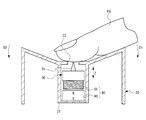
図1ないし図5は本発明の実施例1を示す図であって、図1は本発明の実施例1に係る操作デバイスの外観斜視図、図2は操作デバイスの断面図、図3は操作デバイスが適用された電子機器としての電子書籍装置の外観斜視図、図4は電子書籍装置の機能ブロック図、及び、図5は操作デバイスの作用を説明するための断面図である。
この操作デバイス10は、図1及び図2に示すように、オペレータの指等の操作体により操作される被操作体20、被操作体20を揺動自在に支持するケース40、接触体50、接触体50を動かす駆動手段としてのアクチュエータ60、操作信号形成手段としてのスイッチ回路70等から構成されており、シーソースイッチ状に形成されている。尚、アクチュエータ60及び接触体50が触覚情報提示手段を構成している。
1 to 5 are
As shown in FIGS. 1 and 2, the
被操作体20は、樹脂材料等で形成され、中央部に形成されて接触体50及びアクチュエータ60を内蔵すると共に保持する保持部21、凹状に湾曲する上面(表面)20fに形成された開口部22、その両側に突出して形成された所定軸としての支軸23、その下端側に形成されて後述するスプリング30を受け止める受け部24等を備える。この被操作体20は、その支軸23がケース40に形成された支持孔41にそれぞれ挿入されることにより、支軸23を中心に揺動方向D1及びD2に揺動自在に支持されている。
The operated
接触体50は、樹脂材料等で形成され、図1及び図2に示すように、操作体20の保持部21に内蔵されると共にz方向に移動自在に案内保持されており、被操作体20の開口部22から突出してオペレータの指の腹に接触する突起51を備えている。
As shown in FIGS. 1 and 2, the
アクチュエータ60は、図1及び図2に示すように、コイル61、磁石62等から構成される電磁アクチュエータであり、コイル61は、接触体50の下端面に固着されていると共に磁石62に対向配置され、磁石62は、保持部21の底部に固定されている。このアクチュエータ60は、ケース40内に設けられた基板75に固定されると共に電気的接続のためにケース40の外部に一部が突出するコイル端子80を通じて電圧が印加される。これにより、アクチュエータ60は、コイル61と磁石62との間に電圧印加方向に応じた力が発生して、接触体50をz方向に振動させる(動かす)。尚、本実施例では、磁石62を保持部21に固定しコイル61を可動としたが、コイル61を保持部21に固定して磁石62を可動とすることも可能である。
As shown in FIGS. 1 and 2, the
スイッチ回路70は、図1及び図2に示すように、導電性材料で形成された、可動端子71、共通端子72、固定端子73,74等から構成され、被操作体20の操作に応じてスイッチング信号を形成するためのものである。
As shown in FIGS. 1 and 2, the
可動端子71は、可撓性を有しかつ共通端子72と電気的に接続されており、梁状に支持されていると共に押圧部材31により押圧されている。この押圧部材31は、被操作体20の受け部24に対向配置され、スプリング30により可動端子71に向けて付勢されている。
可動端子71は、被操作体20が操作されて押圧部材31が支軸23を中心にいずれかの向きに傾斜すると、傾斜した押圧部材31により一端部が押圧されて撓むように形成されている。
共通端子72は、基板75に固定されていると共に、電気的接続のためにケース40の外部に一部が突出するように設けられている。
固定端子73,74は、可動端子71の両端部にそれぞれ対向するように基板75に固定されていると共に電気的接続のためにケース40の外部に一部が突出するように設けられている。
The
The
The
The fixed
このスイッチ回路70では、図2において、被操作体20を揺動方向D1に揺動させると、押圧部材31が可動端子71の一端を押圧し、可動端子71と固定端子73とが電気的に接続され、被操作体20を揺動方向D2に揺動させると、押圧部材31が可動端子71の他端を押圧し、可動端子71と固定端子74とが電気的に接続される。すなわち、スイッチ回路70は、被操作体20の揺動方向に応じて接続状態が変化し、この接続状態の変化に応じてスイッチング信号が形成される。
In the
電子書籍装置800は、図3に示すように、電子書籍データを表示するための液晶表示装置等の表示部810を備えており、その前面に操作デバイス10が電子書籍データのページ送戻用スイッチとして設けられている。
また、電子書籍装置800は、図4に示すように、表示部810及び操作デバイス10に加えて、駆動回路830、プロセッサ840、メモリ850等を備えている。
As shown in FIG. 3, the electronic book device 800 includes a
In addition to the
駆動回路830は、プロセッサ840からの制御指令に応じてアクチュエータ60を駆動する。
メモリ850は、例えば、表示部810に表示すべき電子書籍データや制御プログラムを記憶している。
The
The
プロセッサ840は、所定の制御プログラムに基づいて、電子書籍データを表示部810に表示させる等、電子書籍装置800を総合的に制御する。
また、プロセッサ840は、スイッチ回路70及び駆動回路830と接続されており、操作デバイス10の被操作体20の操作に応じてスイッチ回路70で形成されたスイッチング信号に基づいて、表示部810に表示される電子書籍データのページの送り戻しを制御する。さらに、プロセッサ840は、被操作体20を操作するオペレータの指等に対してページ送戻操作に応じた触覚的情報を提示するために、ページの送り戻し操作に応じて、アクチュエータ60を制御する。
The
The
次に、オペレータによるページの送り戻し操作の一例について説明する。
先ず、図5に示すように、操作デバイス10における被操作体20の揺動方向D1をページ送り方向とし、揺動方向D2をページ戻し方向とする。
オペレータは、例えば、図5に示すように、操作デバイス10における被操作体20の上面20fに指FGを置いた状態で、被操作体20をページ送り方向D1又はページ戻し方向D2に操作することにより、表示部810に表示される電子書籍データのページを捲る。
Next, an example of a page return operation by the operator will be described.
First, as shown in FIG. 5, the swing direction D1 of the operated
For example, as shown in FIG. 5, the operator operates the operated
このとき、電子書籍装置800のプロセッサ840は、被操作体20がページ送り方向D1又はページ戻し方向D2に操作されたことをスイッチ回路70が形成するスイッチング信号から認識すると共に、ページが捲られる毎にアクチュエータ60を駆動して接触体50を上下動させる。
接触体50が上下動すると、図5に示すように、その突起51が被操作体20の開口部22を通じて突出してオペレータの指FGの腹に当たる。これにより、オペレータは触覚を通じてページが捲られたことを認識する。
At this time, the
When the
図6ないし図8は実施例1に係るタイプの操作デバイスの変形例を示す図であって、図6は操作デバイスの外観斜視図、図7は操作デバイスの断面図、及び図8は操作デバイスが適用された電子書籍装置の機能ブロック図である。尚、図6ないし図8において実施例1と同一構成部分については同一の符号を使用している。
この例に示す操作デバイス10Aは、図6及び図7に示すように、被操作体20Aに複数(2つ)の保持部21A,21Bを形成すると共に、保持部21Aに接触体50A及び第1アクチュエータ60A、保持部21Bに接触体50B及び第2アクチュエータ60Bをそれぞれ内蔵するように保持させており、被操作体20Aの上面(表面)20fに形成された2つの開口部22A,22Bを通じて接触体50A,50Bの突起51A,51Bがそれぞれ突出するように形成されている。
すなわち、本例では、接触体50A,50B及び第1及び第2アクチュエータ60A,60Bは、被操作体20に対して、ページ送り操作及びページ戻し操作に対応してそれぞれ設けられている。尚、その他の構成については実施例1と同一である。
FIGS. 6 to 8 are views showing modifications of the operation device of the type according to the first embodiment. FIG. 6 is an external perspective view of the operation device, FIG. 7 is a cross-sectional view of the operation device, and FIG. It is a functional block diagram of an electronic book device to which is applied. 6 to 8, the same reference numerals are used for the same components as those in the first embodiment.
As shown in FIGS. 6 and 7, the
That is, in this example, the
この操作デバイス10Aが適用された電子書籍装置は、図8に示すように、第1アクチュエータ60A及び第2アクチュエータ60Bとこれらを駆動する駆動回路830との間に切替手段としての切替回路870を備えている。
この切替回路870は、ページ送戻操作に応じてプロセッサ840から指令を受けて、第1及び第2アクチュエータ60A,60Bのうち駆動回路830が駆動するアクチュエータを選択的に切替える。具体的には、被操作体20Aがページ送り方向D1に操作された場合には、第2アクチュエータ60Bが選択され、被操作体20Aがページ戻し方向D2に操作された場合には、第1アクチュエータ60Aが選択される。
As shown in FIG. 8, the electronic book apparatus to which the
The
上記構成では、ページ送り時に動く接触体50Bと、ページ戻し時に動く接触体50Bが別々に設けられているので、オペレータはページ送り時には開口部51B上に指を置き、ページ戻し時には開口部51A上に指を置いて操作することができると共に、各々の場合に突起51A,51Bにより触覚的情報を認識できる。これにより、操作性が向上する。
In the above configuration, the
図9は実施例1に係るタイプの操作デバイスのさらに他の変形例を示す断面図である。
図9に示す操作デバイス9は、被操作体20Bに2つの保持部21A,21Bが形成されていると共に、これらの保持部21A,21Bに駆動手段としての2つの圧電素子60−1A,60−1Bが保持されている。そして、2つの圧電素子60−1A,60−1Bには、フィルム状の接触体50−1A,50−1Bが固着されて被操作体20Bの上面(表面)20fから露出している。
FIG. 9 is a cross-sectional view showing still another modification of the operation device of the type according to the first embodiment.
In the operation device 9 shown in FIG. 9, two holding
本例では、2つの圧電素子60−1A,60−1Bに電圧を印加することにより、接触体50−1A,50−1Bを振動させることができ、図6ないし図8において説明した操作デバイス及び電子書籍装置と同様の作用、効果が得られると共に、操作デバイスの小型化、集約化が可能である。 In this example, by applying a voltage to the two piezoelectric elements 60-1A and 60-1B, the contact bodies 50-1A and 50-1B can be vibrated, and the operation device described in FIGS. The same operation and effect as the electronic book apparatus can be obtained, and the operation device can be downsized and integrated.
図10及び図11は実施例1に係るタイプの操作デバイスのさらに他の変形例を示す図であって、図10は断面図であり、図11は駆動手段としての駆動機構の構成図である。
本例に係る操作デバイスは、被操作体20の保持部21に保持された接触体50は、その下端部に突出して形成された係合部52を備えている。一方、駆動機構60−1は、接触体50の係合部52に係合するように配置されたカム部材61−1、カム部材61−1を回動させるモータ62−1等を備えており、この駆動機構60−1は、図示しないケース40に保持されている。
この操作デバイスでは、モータ62−1を回動させることにより、カム部材61−1と接触体50が係合し、接触体50が上下動する。これにより、突起51が被操作体20の開口部22を通じて突出する。
10 and 11 are diagrams showing still another modification of the operation device of the type according to the first embodiment. FIG. 10 is a cross-sectional view, and FIG. 11 is a configuration diagram of a drive mechanism as a drive unit. .
In the operation device according to this example, the
In this operation device, by rotating the motor 62-1, the cam member 61-1 and the
図12及び図13は実施例1に係るタイプの操作デバイスのさらに他の変形例を示す図であって、図12は断面図であり、図13は駆動手段の構成図である。
本例に係る操作デバイスは、接触体50−1が羽根車状に形成されており、接触体50−1の一部としての各羽根51−1が被操作体20の開口部22を通じて露出(あるいは突出)するように設けられている。また、接触体51−2は、図13に示すように、駆動手段としてのモータ60−2によって回動される。
12 and 13 are diagrams showing still another modified example of the operation device of the type according to the first embodiment. FIG. 12 is a cross-sectional view, and FIG. 13 is a configuration diagram of a driving unit.
In the operation device according to this example, the contact body 50-1 is formed in an impeller shape, and each blade 51-1 as a part of the contact body 50-1 is exposed through the
本例の操作デバイスでは、接触体50−1が回動すると、その羽根51−1が開口部22から露出してオペレータの指の腹に接触する。これにより、オペレータは触覚的情報を認識できる。また、上記したように、電子書籍装置におけるページ送戻操作の操作方向に応じて接触体50−1の回動方向を変更すれば、オペレータに対してページ送りとページ戻しに対応する触覚的情報を提示できる。
In the operation device of this example, when the contact body 50-1 rotates, the blade 51-1 is exposed from the
図14は本発明の実施例2に係る操作デバイスの外観斜視図であり、図15は操作デバイスの断面図である。尚、図14及び図15において、上記実施例1と同一構成部分については同一の符号を使用している。
この操作デバイス110は、図14及び図15に示すように、接触体50、接触体50を動かす駆動手段としてのアクチュエータ60と共に、オペレータの指等の操作体により操作される被操作体120、被操作体120をスライド方向S1及びS2にスライド自在に支持するケース140、操作信号形成手段としてのスイッチ回路170等から構成されており、スライドスイッチ状に形成されている。
FIG. 14 is an external perspective view of the operating device according to the second embodiment of the present invention, and FIG. 15 is a cross-sectional view of the operating device. 14 and 15, the same reference numerals are used for the same components as those in the first embodiment.
As shown in FIGS. 14 and 15, the
この被操作体120は、図示しない案内機構によりスライド方向S1及びS2にスライド自在に支持されており、その保持部121に接触体50及びアクチュエータ60を内蔵するように保持している。
接触体50は、その突起51が被操作体120の上面(表面)120fに形成された開口部122を通じて突出可能に設けられている。
The operated
The
スイッチ回路170は、被操作体120の保持部121の下端部に設けられたばね部材130により下方に向けて付勢された接続部材171、基板175に固定されてその一部がそれぞれケース140の外部に突出するように設けられた共通端子172、固定端子173,174等から構成される。
このスイッチ回路170は、被操作体120をスライド方向S1にスライドさせると、共通端子172と固定端子173とが接続部材171により電気的に接続され、被操作体120をスライド方向S2にスライドさせると、共通端子172と固定端子174とが接続部材171により電気的に接続され、スライド方向に応じて接続状態が変化する。
The
When the operated
上記構成の操作デバイス110を電子書籍装置へ適用することにより、実施例1と同様の作用、効果が得られる。
By applying the
図16は実施例2に係る操作デバイスの他の例を示す斜視図であり、図17は図16の被操作体の断面図である。尚、図16及び図17において、上記実施例2と同一構成部分については同一の符号を使用している。
本例の操作デバイス110Aは、図16及び図17に示すように、操作体120Aの上面(表面)120fに露出するように設けられたフィルム状の接触体150と、操作体120Aに保持されると共に接触体150が固着された駆動手段としの圧電素子160とを備えている。
圧電素子160に電圧を印加すれば、フィルム状の接触体150を振動させることができ、フィルム状の接触体150に触れるオペレータに触覚的情報を提示できる。
FIG. 16 is a perspective view illustrating another example of the operation device according to the second embodiment, and FIG. 17 is a cross-sectional view of the operated object of FIG. 16 and 17, the same reference numerals are used for the same components as those in the second embodiment.
As shown in FIGS. 16 and 17, the
When a voltage is applied to the
図18は実施例2に係るタイプの操作デバイスのさらに他の例を示す斜視図であり、図19は図18の操作デバイスにおける接触体及び駆動手段を示す斜視図である。
本例の操作デバイス110Bは、図18に示すように、操作体120Bの上面(表面)120fに形成された開口部122Bから一部が露出するように設けられた羽根車状(あるいは歯車状)の接触体150−1を備えている。
羽根車状の接触体150−1を回動させる駆動手段としての駆動機構160−1は、図19に示すように、モータ161、モータ161と接続されたプーリ162、羽根車状の接触体150−1と連結されたプーリ164、プーリ162とプーリ164との巻回されたベルト163等から構成される。
FIG. 18 is a perspective view showing still another example of the operation device of the type according to the second embodiment, and FIG. 19 is a perspective view showing a contact body and driving means in the operation device of FIG.
As shown in FIG. 18, the
As shown in FIG. 19, a driving mechanism 160-1 as a driving unit that rotates the impeller-shaped contact body 150-1 includes a
本例の操作デバイス110Bでは、接触体150−1が回動すると、その羽根150−1aがオペレータの指の腹に接触する。これにより、オペレータは触覚的情報を認識できる。また、被操作体120Bのスライド方向S1,S2に応じて接触体150−1の回動方向を変更すれば、オペレータに対して操作方向に対応する触覚的情報を提示できる。
In the
図20は実施例2に係るタイプの操作デバイスのさらに他の例を示す斜視図であり、図21は図20の操作デバイスにおける接触体及び駆動手段を示す斜視図である。
本例の操作デバイス110Cは、図20に示すように、操作体120Cの上面(表面)120fに形成された開口部122Cから一部が露出するように設けられた無端ベルト状に形成された接触体150−2を備えている。
無端ベルト状に形成された接触体150−2は、図21に示すように、その外周面に複数の突起150−2aが略等間隔で形成されている。
FIG. 20 is a perspective view showing still another example of the operation device of the type according to the second embodiment, and FIG. 21 is a perspective view showing a contact body and driving means in the operation device of FIG.
As shown in FIG. 20, the
As shown in FIG. 21, the contact body 150-2 formed in an endless belt shape has a plurality of protrusions 150-2a formed at substantially equal intervals on the outer peripheral surface thereof.
無端ベルト状の接触体150−1を走行させる駆動手段としての駆動機構160−2は、図21に示すように、モータ161、プーリ162、163、ベルト164、無端ベルト状の接触体150−2が巻回されるプーリ165,166等から構成される。
As shown in FIG. 21, a driving mechanism 160-2 as a driving means for causing the endless belt-shaped contact body 150-1 to travel includes a
本例の操作デバイス110Cでは、モータ161を回動させると、その回動方向に応じて接触体150−2が走行し、突起150−2aがオペレータの指の腹に接触する。これにより、オペレータは触覚的情報を認識できる。また、被操作体120Cのスライド方向S1,S2に応じて接触体150−2の走行方向を変更すれば、オペレータに対して操作方向に対応する触覚的情報を提示できる。
In the operation device 110C of this example, when the
図22ないし図25は本発明の実施例3を示す図であって、図22は操作デバイスの要部断面図、図23は操作デバイスの動作状態を示す断面図、図24は検出素子の出力電圧を示すグラフ、及び、図25は電子書籍装置の機能ブロック図である。尚、図22ないし図25において、上記実施例1と同一構成部分については同一の符号を使用している。
本実施例に係る操作デバイス210は、実施例1におけるスイッチ回路70に代えて、複数の磁電変換素子(検出素子)300(300A,300B)を備えている。尚、磁電変換素子300A,300Bは、図示しないケース40に固定されている。
この磁電変換素子300は、被操作体20の操作量を検出するために設けられていると共に、被操作体20の操作方向を特定するために複数設けられており、被操作体20に対する操作に応じた操作信号を形成する操作信号形成手段を構成している。
22 to 25 are diagrams showing a third embodiment of the present invention, in which FIG. 22 is a cross-sectional view of the main part of the operating device, FIG. 23 is a cross-sectional view showing the operating state of the operating device, and FIG. FIG. 25 is a functional block diagram of the electronic book device. 22 to 25, the same reference numerals are used for the same components as those in the first embodiment.
The
The
磁電変換素子300A,300Bは、アクチュエータ60の磁石62の発生する磁束を検出し、その強さに応じた電圧を出力する。
具体的には、図23(A)に示すように、被操作体20が傾斜して磁石62が磁電変換素子300Aに近づくと、磁電変換素子300Aの出力電圧が増加すると共に磁電変換素子300Bの出力電圧が減少し、図23(B)に示すように、被操作体20が傾斜して磁石62が磁電変換素子300Bに近づくと、磁電変換素子300Bの出力電圧が増加すると共に磁電変換素子300Aの出力電圧が減少する。
すなわち、図24に示すように、被操作体20の操作量に応じて、磁電変換素子300Aの出力電圧はグラフ(1)のように変化し、磁電変換素子300Bの出力電圧はグラフ(2)のように変化する。
The
Specifically, as shown in FIG. 23A, when the
That is, as shown in FIG. 24, the output voltage of the
操作デバイス210を備えた電子書籍装置は、図25に示すように、磁電変換素子300A,300Bのアナログ信号からなる出力電圧をディジタル信号に変換するA/D変換器880を備えており、A/D変換器880で変換された信号はプロセッサ840へ出力される。
As shown in FIG. 25, the electronic book apparatus including the
この電子書籍装置では、被操作体20の操作量に応じてアクチュエータ60の動作パターンを制御する。具体的には、例えば、被操作体20の操作量が比較的小さい場合には、アクチュエータ60の駆動時間を短くし、被操作体20の操作量が比較的大きい場合には、アクチュエータ60の駆動時間を長くするなどの制御を実行する。これにより、オペレータに操作量に応じた触覚的情報を提示可能となる。
また、アクチュエータ60の駆動時間以外にも、アクチュエータ60の駆動周波数、アクチュエータ60の駆動量(振幅)等を被操作体20の操作量に応じて制御してもよい。
さらに、被操作体20の操作量と送戻すべきページ数とを対応付けることにより、操作量が小さいうちは捲ったページ数が少なく、操作量が大きくなると捲ったページ数も増えたことをオペレータに認識させることができる。
In this electronic book apparatus, the operation pattern of the
In addition to the drive time of the
Further, by associating the operation amount of the operated
図26は実施例3に係る操作デバイスの変形例の要部断面図である。尚、図26において、上記実施例1と同一構成部分については同一の符号を使用している。
図26に示す操作デバイスは、保持部21の下端部に設けられた光線Lを出力する発光素子300−1と、図示しないケース40に設けられた複数の受光素子300−2A,300−2Bとを備えている。
この操作デバイスでは、受光素子300−2A,300−2Bは、発光素子300−1から受光する受光量を電気信号に変換してA/D変換器880に出力する。このとき、受光素子300−2A,300−2Bの受光量は、被操作体20の操作量に応じて変化する。これにより、実施例3と同様に被操作体20の操作量及び操作方向を特定できる。
FIG. 26 is a cross-sectional view of main parts of a modification of the operation device according to the third embodiment. In FIG. 26, the same reference numerals are used for the same components as in the first embodiment.
The operation device shown in FIG. 26 includes a light emitting element 300-1 that outputs a light beam L provided at the lower end of the holding
In this operation device, the light receiving elements 300-2A and 300-2B convert the amount of received light received from the light emitting element 300-1 into an electrical signal and output it to the A /
図27及び図28は本発明の実施例4を示す図であって、図27は本発明の実施例4にに係る操作デバイスの要部断面図、及び図28は図27の操作デバイスが適用された電子書籍装置の機能ブロック図である。尚、図27及び図28において、実施例3と同じ構成については同一符号を使用している。
本実施例に係る操作デバイス310は、被操作体20Eの操作に要する操作力を変更するために、被操作体20に対して操作方向D1,D2に反する向きに力を作用させる操作力変更用アクチュエータとしての2つの電磁ソレノイドアクチュエータ400A,400Bを備える。
電磁ソレノイドアクチュエータ400A,400Bは、図示しないケース40と被操作体20Eとの間に配置されていると共に、被操作体20Eの各々の操作方向(揺動方向)D1,D2に対応して設けられている。
27 and 28 are diagrams showing a fourth embodiment of the present invention. FIG. 27 is a cross-sectional view of an essential part of the operation device according to the fourth embodiment of the present invention, and FIG. 28 is applied to the operation device of FIG. It is a functional block diagram of the made electronic book apparatus. 27 and 28, the same reference numerals are used for the same configurations as those in the third embodiment.
The
The
電磁ソレノイドアクチュエータ400A,400Bは、それぞれソレノイドコイル401A,401Bと可動鉄心402A,402Bとを備えており、ソレノイドコイル401A,401Bに通電することにより、可動鉄心402A,402Bがz方向に直動する。
The
操作デバイス310を備えた電子書籍装置は、図28に示すように、電磁ソレノイドアクチュエータ400A,400Bを駆動する駆動回路890を備えている。
この電子書籍装置では、例えば、被操作体20Eが操作方向D1に操作される場合には、電磁ソレノイドアクチュエータ400Bを駆動して操作方向D1に反する向きの力を被操作体20に作用させ、被操作体20Eが操作方向D2に操作される場合には、電磁ソレノイドアクチュエータ400Aを駆動して操作方向D2に反する向きの力を被操作体20に作用させる。そして、電磁ソレノイドアクチュエータ400A,400Bに発生させる力を制御することにより、被操作体20Eの操作に要する操作力を制御(変更)する。
電子書籍装置は、具体的には、例えば、被操作体20Eの操作量に応じて操作力を制御し、操作量が小さい状態(捲ったページが少ない状態)では大きな操作力が必要になるように制御し、操作量の増加(捲ったページが増加)すると共に小さな操作力となるように制御する。このように制御すれば、捲るべきページ数情報を被操作体20Eに要する操作力に変えてオペレータに提示することができる。
As shown in FIG. 28, the electronic book apparatus including the
In this electronic book apparatus, for example, when the operated
Specifically, for example, the electronic book device controls the operation force in accordance with the operation amount of the operated
図29は実施例4に係るタイプにおける操作デバイスの他の例の要部断面図である。尚、図29において、実施例2ないし実施例4と同一構成部分については同一の符号を使用している。
上記実施例4では、揺動自在に支持された被操作体を備える操作デバイスの場合について説明したが、図29に示す操作デバイスは、スライド自在に支持された被操作体120に対して操作力変更用アクチュエータを適用した例を示している。
図29において、操作力変更用アクチュエータ500は、スライド方向S1,S2に沿って磁極の向きが反対になるようにヨーク505上に並列された磁石502,503と、保持部121の下端部に固定されたヨーク504上に磁石502,503に対向するように配置されたコイル501等から構成されている。尚、ヨーク504,505は磁気回路を形成するために設置されており、また、ヨーク504上には被操作体120のスライド方向における位置を検出するための磁電変換素子300が設置されている。
FIG. 29 is a cross-sectional view of main parts of another example of the operation device of the type according to the fourth embodiment. In FIG. 29, the same reference numerals are used for the same components as those in the second to fourth embodiments.
In the above-described fourth embodiment, the case of the operation device including the operated body that is swingably supported has been described. However, the operation device illustrated in FIG. 29 has an operating force applied to the operated
In FIG. 29, the operating
この操作デバイスでは、コイル501への通電制御を実行することにより、コイル501と磁石502,503との間に電磁力が生じ、被操作体120の操作方向S1,S2に反する向きの力を発生させ、被操作体120の操作によるする操作力を制御(変更)できる。
In this operation device, by performing energization control on the
上記実施例においては、スイッチ回路70に代えて磁電変換素子300を使用した場合について説明したが、スイッチ回路170に代えて磁電変換素子300を使用することも可能である。
In the above-described embodiment, the case where the
上記実施例においては、本発明の操作デバイスが適用される電子機器として電子書籍装置を例に挙げて説明したが、これに限定されるわけではなく、例えば、携帯情報端末など様々な電子機器に適用できる。 In the above embodiment, an electronic book apparatus has been described as an example of an electronic apparatus to which the operation device of the present invention is applied. However, the present invention is not limited to this, for example, various electronic apparatuses such as a portable information terminal. Applicable.
10,10A…操作デバイス
20,20A〜20D…被操作体
21…保持部
22…開口部
23…支軸
24…受け部
30…スプリング
31…押圧部材
40…ケース
41…支持孔
50…接触体
51…突起
60…電磁アクチュエータ(駆動手段)
60A…第1アクチュエータ
60B…第2アクチュエータ
61…コイル
62…磁石
70…スイッチ回路
71…可動端子
72…共通端子
73,74…固定端子
80…コイル端子
110,210,310…操作デバイス
120…被操作体
121…保持部
122…開口部
170…スイッチ回路
171…接続部材
172…共通端子
173,74…固定端子
300…磁電変換素子
400A,400B…電磁ソレノイドアクチュエータ(操作力変更用アクチュエータ)
500…操作力変更用アクチュエータ
800…電子書籍装置
810…表示部
830…駆動回路
840…プロセッサ
850…メモリ
870…切替回路(切替手段)
880…A/D変換器
890…駆動回路
FG…指(操作体)
DESCRIPTION OF
60A ...
500 ... Actuating force changing actuator 800 ...
880 ... A /
Claims (37)
前記被操作体に対する操作に応じた操作信号を形成するための操作信号形成手段と、
前記被操作体を操作する前記操作体に対して触覚的情報を提示する触覚情報提示手段と、
を有することを特徴とする操作デバイス。 An object to be operated by the operation body;
An operation signal forming means for forming an operation signal according to an operation on the object to be operated;
Tactile information presentation means for presenting tactile information to the operating body that operates the operated body;
An operating device comprising:
前記接触体を動かす駆動手段と、
を有することを特徴とする請求項1に記載の操作デバイス。 The tactile information presenting means is provided on the operated body and is provided so as to be able to contact the operating body;
Drive means for moving the contact body;
The operating device according to claim 1, comprising:
ことを特徴とする請求項2に記載の操作デバイス。 The operated object holds the contact body,
The operating device according to claim 2.
ことを特徴とする請求項3に記載の操作デバイス。 The contact body is built in the operated body.
The operation device according to claim 3.
ことを特徴とする請求項2ないし4のいずれかに記載の操作デバイス。 The operated body holds the driving means,
The operating device according to any one of claims 2 to 4, wherein
ことを特徴とする請求項2ないし5のいずれかに記載の操作デバイス。 The operated body incorporates the driving means.
The operation device according to claim 2, wherein the operation device is a device.
ことを特徴とする請求項2ないし6のいずれかに記載の操作デバイス。 A plurality of the contact bodies are provided for the operated body.
The operation device according to claim 2, wherein the operation device is a device.
ことを特徴とする請求項2ないし7のいずれかに記載の操作デバイス。 The contact body is provided so as to protrude through an opening formed on the surface of the operated body.
The operation device according to claim 2, wherein the operation device is a device.
ことを特徴とする請求項8に記載の操作デバイス。 The contact body includes a protrusion that is built in the object to be operated and protrudes through the opening.
The operating device according to claim 8.
ことを特徴とする請求項2ないし7のいずれかに記載の操作デバイス。 The contact body is provided so as to be exposed on the surface of the operated body.
The operation device according to claim 2, wherein the operation device is a device.
前記接触体は、フィルム状に形成されていると共に前記圧電素子に固着されている、
ことを特徴とする請求項10に記載の操作デバイス。 The driving means is composed of a piezoelectric element provided on the operated body,
The contact body is formed in a film shape and is fixed to the piezoelectric element.
The operation device according to claim 10.
ことを特徴とする請求項2ないし7のいずれかに記載の操作デバイス。 The contact body is provided so that a part thereof is exposed through an opening formed on a surface of the operated body.
The operation device according to claim 2, wherein the operation device is a device.
前記駆動手段は、前記羽根車状の接触体を回動させるモータを含む、
ことを特徴とする請求項12に記載の操作デバイス。 The contact body is formed in an impeller shape,
The drive means includes a motor that rotates the impeller-like contact body.
The operation device according to claim 12.
前記駆動手段は、前記無端ベルト状の接触体を双方向に走行させるためのモータを含む、
ことを特徴とする請求項12に記載の操作デバイス。 The contact body is formed in an endless belt shape having a plurality of protrusions on its outer peripheral surface,
The driving means includes a motor for causing the endless belt-like contact body to travel in both directions,
The operation device according to claim 12.
ことを特徴とする請求項2に記載の操作デバイス。 The operation signal forming means includes a switch circuit for forming a switching signal according to the operation of the operated object.
The operating device according to claim 2.
前記スイッチ回路は、前記被操作体の揺動方向に応じて接続状態が変化する、
ことを特徴とする請求項15に記載の操作デバイス。 The operated body is supported to be swingable about a predetermined axis,
The switch circuit changes a connection state according to a swinging direction of the operated body.
The operation device according to claim 15.
前記スイッチ回路は、前記被操作体のスライド方向に応じて接続状態が変化する、
ことを特徴とする請求項15に記載の操作デバイス。 The operated object is guided to be slidable in a predetermined direction,
The switch circuit changes a connection state according to a sliding direction of the operated body.
The operation device according to claim 15.
ことを特徴とする請求項2に記載の操作デバイス。 The operation signal forming means includes a detection element for detecting an operation amount of the operated object.
The operating device according to claim 2.
ことを特徴とする請求項18に記載の操作デバイス。 The operation signal forming means includes a plurality of the detection elements to specify an operation direction of the operated body.
The operation device according to claim 18.
ことを特徴とする請求項18又は19に記載の操作デバイス。 The detection element includes a light-emitting element provided in the object to be operated, and a light-receiving element that converts the amount of light received from the light-emitting element into an electrical signal.
The operation device according to claim 18 or 19, characterized in that
ことを特徴とする請求項18又は19に記載の操作デバイス。 The detection element includes a magnetoelectric conversion element that detects a magnetic flux generated by the driving means.
The operation device according to claim 18 or 19, characterized in that
前記コイル及び磁石の一方が接触体と連結されており、他方が前記被操作体に固定されている、
ことを特徴とする請求項2ないし7のいずれかに記載の操作デバイス。 The drive means is composed of an electromagnetic actuator including a coil and a magnet arranged to face each other,
One of the coil and magnet is connected to a contact body, and the other is fixed to the operated body.
The operation device according to claim 2, wherein the operation device is a device.
ことを特徴とする請求項2ないし7のいずれかに記載の操作デバイス。 The driving means includes a cam member provided so as to engage with the contact body, and a motor for rotating the cam member.
The operation device according to claim 2, wherein the operation device is a device.
ことを特徴とする操作デバイス。 The tactile information presentation means includes an operation force changing actuator that applies a force in a direction opposite to an operation direction to the operated body in order to change an operating force required for operating the operated body.
An operation device characterized by that.
前記操作力変更用アクチュエータは、前記被操作体の各々の揺動方向に対応して設けられた2つの電磁ソレノイドアクチュエータを含む、
ことを特徴とする請求項24に記載の操作デバイス。 The operated body is supported to be swingable about a predetermined axis,
The operating force changing actuator includes two electromagnetic solenoid actuators provided corresponding to the swing directions of the operated body,
25. The operating device according to claim 24.
前記操作力変更用アクチュエータは、前記スライド方向に沿って磁極の向きが反対になるように並列された磁石と、前記磁石に対向配置されたコイルとを含み、
前記コイルが前記被操作体に連結されている、
ことを特徴とする請求項24に記載の操作デバイス。 The operated body is guided to be slidable in a predetermined sliding direction,
The operating force changing actuator includes a magnet arranged in parallel so that the direction of the magnetic poles is opposite along the sliding direction, and a coil disposed to face the magnet,
The coil is connected to the object to be operated;
25. The operating device according to claim 24.
前記電子書籍データのページを送戻するための操作デバイスを備え、
前記操作デバイスは、操作体によりページ送戻操作を受ける被操作体と、
前記被操作体に対するページ送戻操作に応じた信号を形成するための操作信号形成手段と、
前記被操作体を操作する前記操作体に対して前記ページ送戻操作に応じた触覚的情報を提示する触覚情報提示手段と、
を有することを特徴とする電子書籍装置。 An electronic book device that displays electronic book data on a display screen,
An operation device for sending back the electronic book data page;
The operation device includes an operated body that receives a page return operation by the operating body,
An operation signal forming means for forming a signal according to a page feed back operation on the operated object;
Tactile information presenting means for presenting tactile information corresponding to the page feed back operation to the operating body for operating the operated body;
An electronic book device comprising:
前記被操作体に対するページ送戻操作に応じて前記駆動手段を制御する
ことを特徴とする請求項27に記載の電子書籍装置。 The tactile information presenting means includes a contact body provided on the operated body and capable of contacting the operating body, and a driving unit that moves the contact body.
28. The electronic book apparatus according to claim 27, wherein the driving unit is controlled in accordance with a page feed back operation on the operated body.
ページ送戻操作に応じて、制御する駆動手段を切替える切替手段を有することを特徴とする請求項28に記載の電子書籍装置。 The contact body and the driving means are provided corresponding to a page turning operation and a page returning operation with respect to the operated body,
29. The electronic book apparatus according to claim 28, further comprising a switching unit that switches a driving unit to be controlled in accordance with a page sending back operation.
ことを特徴とする請求項28又は29に記載の電子書籍装置。 Each time the page of the electronic book data is turned by the page return operation, the contact body is moved.
30. The electronic book apparatus according to claim 28 or 29.
ことを特徴とする請求項28に記載の電子書籍装置。 Changing the direction of moving the contact body according to the operation direction of the page feed back operation;
29. The electronic book apparatus according to claim 28, wherein:
ことを特徴とする請求項28ないし31のいずれかに記載の電子書籍装置。 Changing an operation pattern of the contact body according to an operation amount of a page feed back operation on the operated body;
32. The electronic book apparatus according to any one of claims 28 to 31, wherein
前記ページ送戻操作に応じて操作力変更用アクチュエータを制御する
ことを特徴とする請求項27に記載の電子書籍装置。 The tactile sensation information presenting means includes an operation force changing actuator that applies a force to the operated object in a direction opposite to the operation direction in order to change the operation force required for the page return operation of the operated object. And
28. The electronic book apparatus according to claim 27, wherein an actuator for changing an operating force is controlled in accordance with the page feed back operation.
ことを特徴とする請求項33に記載の電子書籍装置。 Controlling the force generated by the operating force changing actuator according to the amount of operation with respect to the object to be operated;
34. The electronic book apparatus according to claim 33.
前記操作デバイスは、前記被操作体に対する操作に応じた信号を形成するための操作信号形成手段と、
前記被操作体を操作する前記操作体に対して操作に応じた触覚的情報を提示する触覚情報提示手段と、
を有することを特徴とする電子機器。 An electronic device including an operation device for forming an operation signal according to an operation by an operation body,
The operation device includes an operation signal forming means for forming a signal according to an operation on the operated object;
Tactile information presenting means for presenting tactile information corresponding to the operation to the operating body for operating the operated body;
An electronic device comprising:
前記被操作体に対する操作に応じて前記駆動手段を制御する、
ことを特徴とする請求項35に記載の電子機器。 The tactile information presenting means includes a contact body provided on the operated body and capable of contacting the operating body, and a driving unit that moves the contact body.
Controlling the driving means according to an operation on the object to be operated;
36. The electronic device according to claim 35.
前記操作に応じて操作力変更用アクチュエータを制御する、
ことを特徴とする請求項35に記載の電子機器。
The tactile information presentation means includes an operation force changing actuator that applies a force in a direction opposite to an operation direction to the operated body in order to change an operating force required for operating the operated body.
Controlling the operating force changing actuator according to the operation,
36. The electronic device according to claim 35.
Priority Applications (2)
| Application Number | Priority Date | Filing Date | Title |
|---|---|---|---|
| JP2005226186A JP4684794B2 (en) | 2005-08-04 | 2005-08-04 | Operation device, electronic book apparatus, and electronic apparatus |
| US11/497,289 US8077165B2 (en) | 2005-08-04 | 2006-08-02 | Operation device, electronic book device and electronic apparatus |
Applications Claiming Priority (1)
| Application Number | Priority Date | Filing Date | Title |
|---|---|---|---|
| JP2005226186A JP4684794B2 (en) | 2005-08-04 | 2005-08-04 | Operation device, electronic book apparatus, and electronic apparatus |
Publications (2)
| Publication Number | Publication Date |
|---|---|
| JP2007041895A true JP2007041895A (en) | 2007-02-15 |
| JP4684794B2 JP4684794B2 (en) | 2011-05-18 |
Family
ID=37718974
Family Applications (1)
| Application Number | Title | Priority Date | Filing Date |
|---|---|---|---|
| JP2005226186A Expired - Fee Related JP4684794B2 (en) | 2005-08-04 | 2005-08-04 | Operation device, electronic book apparatus, and electronic apparatus |
Country Status (2)
| Country | Link |
|---|---|
| US (1) | US8077165B2 (en) |
| JP (1) | JP4684794B2 (en) |
Cited By (8)
| Publication number | Priority date | Publication date | Assignee | Title |
|---|---|---|---|---|
| KR100958908B1 (en) | 2008-09-24 | 2010-05-19 | 한국과학기술연구원 | Tactile presentation device and tactile presentation method using the same |
| JP2017073100A (en) * | 2015-10-05 | 2017-04-13 | 株式会社ミライセンス | Tactile and force information providing system |
| JP2019125425A (en) * | 2018-01-12 | 2019-07-25 | アルプスアルパイン株式会社 | Input device |
| JP2020102279A (en) * | 2020-04-06 | 2020-07-02 | 株式会社ミライセンス | Tactile force information display system |
| US11287892B2 (en) | 2015-10-05 | 2022-03-29 | Murata Manufacturing Co., Ltd. | Haptic information presentation system |
| US11287888B2 (en) | 2003-11-20 | 2022-03-29 | National Institute Of Advanced Industrial Science And Technology | Haptic information presentation system and method |
| US11385723B2 (en) | 2003-11-20 | 2022-07-12 | National Institute Of Advanced Industrial Science And Technology | Haptic information presentation system and method |
| JP7487071B2 (en) | 2020-05-28 | 2024-05-20 | 株式会社東海理化電機製作所 | Operating device |
Families Citing this family (6)
| Publication number | Priority date | Publication date | Assignee | Title |
|---|---|---|---|---|
| JP4916900B2 (en) * | 2007-01-25 | 2012-04-18 | 富士通コンポーネント株式会社 | Direction presenting system, and electric wheelchair, cane and game controller to which the direction presenting system is applied |
| DE102009026214B4 (en) * | 2009-07-21 | 2012-04-26 | Gbs Holding Gmbh | slide switches |
| FR2962566B1 (en) * | 2010-07-06 | 2013-05-17 | Commissariat Energie Atomique | SIMULATION SYSTEM FOR CONTACT WITH A SURFACE BY TOUCH STIMULATION |
| CN102022281A (en) * | 2010-12-22 | 2011-04-20 | 鸿富锦精密工业(深圳)有限公司 | Electronic device with wind power control function |
| DE102011079863A1 (en) * | 2011-07-26 | 2013-01-31 | Continental Automotive Gmbh | operating device |
| CN105975111A (en) * | 2016-06-16 | 2016-09-28 | 乐视控股(北京)有限公司 | Touch operation method and device and terminal |
Citations (15)
| Publication number | Priority date | Publication date | Assignee | Title |
|---|---|---|---|---|
| JPH06259189A (en) * | 1993-02-05 | 1994-09-16 | Federico G Gilligan | Mouse and method for simultaneous control of cursor position and scrolling |
| JPH06278056A (en) * | 1993-03-26 | 1994-10-04 | Olympus Optical Co Ltd | Touch indicator |
| JPH07146751A (en) * | 1993-05-11 | 1995-06-06 | Matsushita Electric Ind Co Ltd | Force display device, data input device, and data input device |
| JPH07244558A (en) * | 1994-03-07 | 1995-09-19 | Sharp Corp | Tactile presentation device |
| JPH11312041A (en) * | 1998-04-28 | 1999-11-09 | Nippon Telegr & Teleph Corp <Ntt> | Input device, page turning device, and book type electronic information browsing device |
| JP2000181428A (en) * | 1996-12-03 | 2000-06-30 | Nec Corp | Information display device |
| JP2000267784A (en) * | 1999-03-16 | 2000-09-29 | Fuji Xerox Co Ltd | Device for presenting tactile sense |
| JP2000330688A (en) * | 1999-03-17 | 2000-11-30 | Fuji Xerox Co Ltd | Information sensing device, information transmitting system and storage medium for storing program for controlling the device |
| JP2002007065A (en) * | 2000-06-23 | 2002-01-11 | Fuji Xerox Co Ltd | Pointing device and information processor |
| JP2003097964A (en) * | 2001-09-26 | 2003-04-03 | Nissan Motor Co Ltd | Input control device |
| JP2003331674A (en) * | 2002-05-14 | 2003-11-21 | Konica Minolta Holdings Inc | Switch and image forming device |
| JP2004157944A (en) * | 2002-11-08 | 2004-06-03 | Denso Corp | Input device |
| JP2005004365A (en) * | 2003-06-10 | 2005-01-06 | Fujitsu Component Ltd | Input device |
| JP2005010729A (en) * | 2002-12-10 | 2005-01-13 | Ask:Kk | Tactile pin holding device and tactile pin display device |
| JP2005514681A (en) * | 2001-10-23 | 2005-05-19 | イマージョン コーポレーション | Method of using haptic feedback by communicating a static state to a user of an electronic device |
Family Cites Families (17)
| Publication number | Priority date | Publication date | Assignee | Title |
|---|---|---|---|---|
| US4324958A (en) * | 1980-08-18 | 1982-04-13 | Switchcraft, Inc. | Tactile switch device |
| JPH08249344A (en) | 1995-03-10 | 1996-09-27 | N T T Data Tsushin Kk | E-book device |
| US6128006A (en) * | 1998-03-26 | 2000-10-03 | Immersion Corporation | Force feedback mouse wheel and other control wheels |
| US6686911B1 (en) * | 1996-11-26 | 2004-02-03 | Immersion Corporation | Control knob with control modes and force feedback |
| KR100405018B1 (en) * | 1998-02-25 | 2003-11-07 | 샤프 가부시키가이샤 | Display device |
| US6429846B2 (en) * | 1998-06-23 | 2002-08-06 | Immersion Corporation | Haptic feedback for touchpads and other touch controls |
| JP2000123678A (en) | 1998-10-16 | 2000-04-28 | Horiba Ltd | Switch |
| JP2000173397A (en) | 1998-12-07 | 2000-06-23 | Sony Corp | Switch device |
| US6692255B2 (en) * | 1999-05-19 | 2004-02-17 | The United States Of America | Apparatus and method utilizing bi-directional relative movement for refreshable tactile display |
| JP3766251B2 (en) * | 2000-02-16 | 2006-04-12 | アルプス電気株式会社 | Switch device |
| JP3858642B2 (en) * | 2001-08-17 | 2006-12-20 | 富士ゼロックス株式会社 | Operation switch device |
| US7071915B2 (en) | 2001-09-13 | 2006-07-04 | E-Book Systems Pte Ltd. | Method for displaying flipping pages via electromechanical information browsing device |
| JP3934394B2 (en) * | 2001-10-30 | 2007-06-20 | アルプス電気株式会社 | Haptic input device |
| EP1429307B1 (en) * | 2002-12-10 | 2005-06-22 | Askk Co.,Ltd. | Rotating braille display device |
| US7081884B2 (en) * | 2003-04-25 | 2006-07-25 | Microsoft Corporation | Computer input device with angular displacement detection capabilities |
| EP1503277B1 (en) * | 2003-07-28 | 2007-12-19 | Alps Electric Co., Ltd. | Coordinate input device |
| US7499040B2 (en) * | 2003-08-18 | 2009-03-03 | Apple Inc. | Movable touch pad with added functionality |
-
2005
- 2005-08-04 JP JP2005226186A patent/JP4684794B2/en not_active Expired - Fee Related
-
2006
- 2006-08-02 US US11/497,289 patent/US8077165B2/en not_active Expired - Fee Related
Patent Citations (15)
| Publication number | Priority date | Publication date | Assignee | Title |
|---|---|---|---|---|
| JPH06259189A (en) * | 1993-02-05 | 1994-09-16 | Federico G Gilligan | Mouse and method for simultaneous control of cursor position and scrolling |
| JPH06278056A (en) * | 1993-03-26 | 1994-10-04 | Olympus Optical Co Ltd | Touch indicator |
| JPH07146751A (en) * | 1993-05-11 | 1995-06-06 | Matsushita Electric Ind Co Ltd | Force display device, data input device, and data input device |
| JPH07244558A (en) * | 1994-03-07 | 1995-09-19 | Sharp Corp | Tactile presentation device |
| JP2000181428A (en) * | 1996-12-03 | 2000-06-30 | Nec Corp | Information display device |
| JPH11312041A (en) * | 1998-04-28 | 1999-11-09 | Nippon Telegr & Teleph Corp <Ntt> | Input device, page turning device, and book type electronic information browsing device |
| JP2000267784A (en) * | 1999-03-16 | 2000-09-29 | Fuji Xerox Co Ltd | Device for presenting tactile sense |
| JP2000330688A (en) * | 1999-03-17 | 2000-11-30 | Fuji Xerox Co Ltd | Information sensing device, information transmitting system and storage medium for storing program for controlling the device |
| JP2002007065A (en) * | 2000-06-23 | 2002-01-11 | Fuji Xerox Co Ltd | Pointing device and information processor |
| JP2003097964A (en) * | 2001-09-26 | 2003-04-03 | Nissan Motor Co Ltd | Input control device |
| JP2005514681A (en) * | 2001-10-23 | 2005-05-19 | イマージョン コーポレーション | Method of using haptic feedback by communicating a static state to a user of an electronic device |
| JP2003331674A (en) * | 2002-05-14 | 2003-11-21 | Konica Minolta Holdings Inc | Switch and image forming device |
| JP2004157944A (en) * | 2002-11-08 | 2004-06-03 | Denso Corp | Input device |
| JP2005010729A (en) * | 2002-12-10 | 2005-01-13 | Ask:Kk | Tactile pin holding device and tactile pin display device |
| JP2005004365A (en) * | 2003-06-10 | 2005-01-06 | Fujitsu Component Ltd | Input device |
Cited By (11)
| Publication number | Priority date | Publication date | Assignee | Title |
|---|---|---|---|---|
| US11287888B2 (en) | 2003-11-20 | 2022-03-29 | National Institute Of Advanced Industrial Science And Technology | Haptic information presentation system and method |
| US11385723B2 (en) | 2003-11-20 | 2022-07-12 | National Institute Of Advanced Industrial Science And Technology | Haptic information presentation system and method |
| KR100958908B1 (en) | 2008-09-24 | 2010-05-19 | 한국과학기술연구원 | Tactile presentation device and tactile presentation method using the same |
| JP2017073100A (en) * | 2015-10-05 | 2017-04-13 | 株式会社ミライセンス | Tactile and force information providing system |
| US11287892B2 (en) | 2015-10-05 | 2022-03-29 | Murata Manufacturing Co., Ltd. | Haptic information presentation system |
| US11308772B2 (en) | 2015-10-05 | 2022-04-19 | Murata Manufacturing Co., Ltd. | Haptic information presentation system |
| US11361632B2 (en) | 2015-10-05 | 2022-06-14 | Murata Manufacturing Co., Ltd. | Haptic information presentation system |
| JP2019125425A (en) * | 2018-01-12 | 2019-07-25 | アルプスアルパイン株式会社 | Input device |
| JP2020102279A (en) * | 2020-04-06 | 2020-07-02 | 株式会社ミライセンス | Tactile force information display system |
| JP7064177B2 (en) | 2020-04-06 | 2022-05-10 | 株式会社村田製作所 | Tactile information presentation system |
| JP7487071B2 (en) | 2020-05-28 | 2024-05-20 | 株式会社東海理化電機製作所 | Operating device |
Also Published As
| Publication number | Publication date |
|---|---|
| JP4684794B2 (en) | 2011-05-18 |
| US20070033541A1 (en) | 2007-02-08 |
| US8077165B2 (en) | 2011-12-13 |
Similar Documents
| Publication | Publication Date | Title |
|---|---|---|
| JP4684794B2 (en) | Operation device, electronic book apparatus, and electronic apparatus | |
| KR102290143B1 (en) | Controlling method of tactile actuator and device | |
| US9829981B1 (en) | Haptic output device | |
| KR101114603B1 (en) | Haptic feedback device for portable terminal | |
| CN102741783B (en) | Operating means | |
| JP5707606B2 (en) | Rotary input device and electronic device | |
| US10671166B2 (en) | Electronic device including Halbach array based haptic actuator and related methods | |
| US10864436B2 (en) | Game controller | |
| CN210776606U (en) | Touch panel module | |
| JP2010262561A (en) | Haptic feedback device and electronic apparatus | |
| US20130314355A1 (en) | Electronic device | |
| JP2013161384A (en) | Input device | |
| JP5930226B2 (en) | Multi-directional input operation device and vehicular shift device using the multi-directional input operation device | |
| JP2007129678A (en) | Actuator, touch panel display device and electronic device | |
| KR20110061227A (en) | Haptic Device | |
| JPH09167541A (en) | Thin-type switch and display panel with switch | |
| JPH09115379A (en) | Thin type switch and display panel with switch | |
| WO2012169138A1 (en) | Input device | |
| JP4289960B2 (en) | Input device and electronic device | |
| JP2006139371A (en) | Input device | |
| JP5871340B2 (en) | Multi-directional input operation device and vehicular shift device using the multi-directional input operation device | |
| KR20100049154A (en) | Handheld providing haptic feedback with hybrid actuator and providing method thereof | |
| JP2007075751A (en) | Tactile sense providing mechanism and electronic device provided with tactile sense providing mechanism | |
| JP6117075B2 (en) | Tactile presentation device | |
| JP2013105192A (en) | Touch panel device |
Legal Events
| Date | Code | Title | Description |
|---|---|---|---|
| A621 | Written request for application examination |
Free format text: JAPANESE INTERMEDIATE CODE: A621 Effective date: 20080516 |
|
| A977 | Report on retrieval |
Free format text: JAPANESE INTERMEDIATE CODE: A971007 Effective date: 20100527 |
|
| A131 | Notification of reasons for refusal |
Free format text: JAPANESE INTERMEDIATE CODE: A131 Effective date: 20100608 |
|
| A521 | Request for written amendment filed |
Free format text: JAPANESE INTERMEDIATE CODE: A523 Effective date: 20100730 |
|
| A131 | Notification of reasons for refusal |
Free format text: JAPANESE INTERMEDIATE CODE: A131 Effective date: 20101116 |
|
| A521 | Request for written amendment filed |
Free format text: JAPANESE INTERMEDIATE CODE: A523 Effective date: 20110117 |
|
| TRDD | Decision of grant or rejection written | ||
| A01 | Written decision to grant a patent or to grant a registration (utility model) |
Free format text: JAPANESE INTERMEDIATE CODE: A01 Effective date: 20110208 |
|
| A01 | Written decision to grant a patent or to grant a registration (utility model) |
Free format text: JAPANESE INTERMEDIATE CODE: A01 |
|
| A61 | First payment of annual fees (during grant procedure) |
Free format text: JAPANESE INTERMEDIATE CODE: A61 Effective date: 20110209 |
|
| FPAY | Renewal fee payment (event date is renewal date of database) |
Free format text: PAYMENT UNTIL: 20140218 Year of fee payment: 3 |
|
| R150 | Certificate of patent or registration of utility model |
Free format text: JAPANESE INTERMEDIATE CODE: R150 |
|
| LAPS | Cancellation because of no payment of annual fees |