JP2007040136A - Exhaust gas recirculation device for an internal combustion engine with a supercharger - Google Patents
Exhaust gas recirculation device for an internal combustion engine with a supercharger Download PDFInfo
- Publication number
- JP2007040136A JP2007040136A JP2005223607A JP2005223607A JP2007040136A JP 2007040136 A JP2007040136 A JP 2007040136A JP 2005223607 A JP2005223607 A JP 2005223607A JP 2005223607 A JP2005223607 A JP 2005223607A JP 2007040136 A JP2007040136 A JP 2007040136A
- Authority
- JP
- Japan
- Prior art keywords
- exhaust gas
- gas recirculation
- exhaust
- valve
- pair
- Prior art date
- Legal status (The legal status is an assumption and is not a legal conclusion. Google has not performed a legal analysis and makes no representation as to the accuracy of the status listed.)
- Pending
Links
Images


Classifications
-
- F—MECHANICAL ENGINEERING; LIGHTING; HEATING; WEAPONS; BLASTING
- F02—COMBUSTION ENGINES; HOT-GAS OR COMBUSTION-PRODUCT ENGINE PLANTS
- F02M—SUPPLYING COMBUSTION ENGINES IN GENERAL WITH COMBUSTIBLE MIXTURES OR CONSTITUENTS THEREOF
- F02M26/00—Engine-pertinent apparatus for adding exhaust gases to combustion-air, main fuel or fuel-air mixture, e.g. by exhaust gas recirculation [EGR] systems
- F02M26/13—Arrangement or layout of EGR passages, e.g. in relation to specific engine parts or for incorporation of accessories
- F02M26/38—Arrangement or layout of EGR passages, e.g. in relation to specific engine parts or for incorporation of accessories with two or more EGR valves disposed in parallel
-
- F—MECHANICAL ENGINEERING; LIGHTING; HEATING; WEAPONS; BLASTING
- F02—COMBUSTION ENGINES; HOT-GAS OR COMBUSTION-PRODUCT ENGINE PLANTS
- F02M—SUPPLYING COMBUSTION ENGINES IN GENERAL WITH COMBUSTIBLE MIXTURES OR CONSTITUENTS THEREOF
- F02M26/00—Engine-pertinent apparatus for adding exhaust gases to combustion-air, main fuel or fuel-air mixture, e.g. by exhaust gas recirculation [EGR] systems
- F02M26/02—EGR systems specially adapted for supercharged engines
- F02M26/08—EGR systems specially adapted for supercharged engines for engines having two or more intake charge compressors or exhaust gas turbines, e.g. a turbocharger combined with an additional compressor
-
- F—MECHANICAL ENGINEERING; LIGHTING; HEATING; WEAPONS; BLASTING
- F02—COMBUSTION ENGINES; HOT-GAS OR COMBUSTION-PRODUCT ENGINE PLANTS
- F02M—SUPPLYING COMBUSTION ENGINES IN GENERAL WITH COMBUSTIBLE MIXTURES OR CONSTITUENTS THEREOF
- F02M26/00—Engine-pertinent apparatus for adding exhaust gases to combustion-air, main fuel or fuel-air mixture, e.g. by exhaust gas recirculation [EGR] systems
- F02M26/13—Arrangement or layout of EGR passages, e.g. in relation to specific engine parts or for incorporation of accessories
- F02M26/22—Arrangement or layout of EGR passages, e.g. in relation to specific engine parts or for incorporation of accessories with coolers in the recirculation passage
- F02M26/23—Layout, e.g. schematics
-
- F—MECHANICAL ENGINEERING; LIGHTING; HEATING; WEAPONS; BLASTING
- F02—COMBUSTION ENGINES; HOT-GAS OR COMBUSTION-PRODUCT ENGINE PLANTS
- F02M—SUPPLYING COMBUSTION ENGINES IN GENERAL WITH COMBUSTIBLE MIXTURES OR CONSTITUENTS THEREOF
- F02M26/00—Engine-pertinent apparatus for adding exhaust gases to combustion-air, main fuel or fuel-air mixture, e.g. by exhaust gas recirculation [EGR] systems
- F02M26/13—Arrangement or layout of EGR passages, e.g. in relation to specific engine parts or for incorporation of accessories
- F02M26/40—Arrangement or layout of EGR passages, e.g. in relation to specific engine parts or for incorporation of accessories with timing means in the recirculation passage, e.g. cyclically operating valves or regenerators; with arrangements involving pressure pulsations
Landscapes
- Engineering & Computer Science (AREA)
- Chemical & Material Sciences (AREA)
- Combustion & Propulsion (AREA)
- Mechanical Engineering (AREA)
- General Engineering & Computer Science (AREA)
- Exhaust-Gas Circulating Devices (AREA)
- Supercharger (AREA)
Abstract
【課題】 ターボ過給機付きV型エンジンEにおける吸入空気の充填効率の向上および一対の第1、第2ターボ過給機1、2の過給効率の向上を図ることを課題とする。
【解決手段】 排気ガス還流管3の一対の第1、第2排気ガス還流管41、42の下流側端部とEGRガスクーラ6の入口部との間に設けられる合流管43のバルブ室の内部に三方切替弁7を設置しているので、V型エンジンEの第1、第2バンク11、12毎に発生した排気脈動圧が、仮に逆位相であっても干渉することはなく、V型エンジンEの第1、第2バンク11、12毎に発生した排気脈動圧が互いに影響を受けなくなる。これによって、一対の第1、第2ターボ過給機1、2の各第1、第2タービン35、36に作用する排気圧力が高くなり、過給効率の高い運転状態を維持できる。そして、一対の第1、第2ターボ過給機1、2の過給効率に応じて吸入空気の充填効率も高くなる。
【選択図】 図1PROBLEM TO BE SOLVED: To improve the charging efficiency of intake air in a V-type engine E with a turbocharger and to improve the supercharging efficiency of a pair of first and second turbochargers 1 and 2.
SOLUTION: The inside of a valve chamber of a merging pipe 43 provided between a downstream end of a pair of first and second exhaust gas reflux pipes 41 and 42 and an inlet part of an EGR gas cooler 6 is provided. Since the three-way switching valve 7 is installed in the V-type engine E, the exhaust pulsation pressure generated for each of the first and second banks 11 and 12 of the V-type engine E will not interfere even if it is in the opposite phase. The exhaust pulsation pressure generated for each of the first and second banks 11 and 12 of the engine E is not affected by each other. As a result, the exhaust pressure acting on each of the first and second turbines 35 and 36 of the pair of first and second turbochargers 1 and 2 becomes high, and an operation state with high supercharging efficiency can be maintained. And the charging efficiency of intake air also becomes high according to the supercharging efficiency of a pair of 1st, 2nd turbocharger 1,2.
[Selection] Figure 1
Description
本発明は、過給機付き内燃機関の排気ガス再循環装置に関するもので、特に複数のバンク毎に独立して設けられた複数の排気ガス還流量制御弁の耐熱性能の向上と、複数のバンク毎に独立して設けられた複数のターボ過給機の過給効率の向上とを図ることが可能な過給機付き内燃機関の排気ガス再循環装置に係わる。 The present invention relates to an exhaust gas recirculation device for an internal combustion engine with a supercharger, and in particular, to improve the heat resistance performance of a plurality of exhaust gas recirculation amount control valves provided independently for each of a plurality of banks, and to a plurality of banks The present invention relates to an exhaust gas recirculation device for an internal combustion engine with a supercharger capable of improving the supercharging efficiency of a plurality of turbochargers provided independently for each.
[従来の技術]
従来より、例えば気筒が群配置された複数のバンクを有するV型エンジン搭載車において、1組のターボチャージャーと、複数のバンク毎に独立して設けられた複数の排気ガス還流管(所謂EGRパイプ)と、これらのEGRパイプ内に形成される各排気ガス還流路をそれぞれ開閉する複数の排気ガス還流量制御弁(所謂EGR制御バルブ)とを備えた過給機付きV型エンジンの排気ガス再循環装置が公知である(例えば、特許文献1及び2参照)。一方、複数のバンク毎に独立して設けられた複数のターボチャージャーと、複数のバンク毎に独立して設けられた排気通路から共通の吸気通路に排気ガスの一部を還流させるEGRパイプと、このEGRパイプ内に形成される排気ガス還流路を開閉する1つのEGR制御バルブとを備えた過給機付きV型エンジンの排気ガス再循環装置が公知である(例えば、特許文献3参照)。
[Conventional technology]
Conventionally, for example, in a V-type engine-equipped vehicle having a plurality of banks in which cylinders are arranged in groups, a set of turbochargers and a plurality of exhaust gas recirculation pipes (so-called EGR pipes) provided independently for each of the plurality of banks. ) And a plurality of exhaust gas recirculation amount control valves (so-called EGR control valves) for opening and closing each exhaust gas recirculation path formed in these EGR pipes. Circulators are known (see, for example, Patent Documents 1 and 2). On the other hand, a plurality of turbochargers provided independently for each of the plurality of banks, an EGR pipe for recirculating a part of the exhaust gas from the exhaust passage provided independently for each of the plurality of banks to the common intake passage, An exhaust gas recirculation device for a V-type engine with a supercharger provided with one EGR control valve that opens and closes an exhaust gas recirculation path formed in the EGR pipe is known (for example, see Patent Document 3).
ここで、複数のバンク毎に独立して設けられた複数のターボチャージャーと、複数のバンク毎に独立して設けられた複数のEGRパイプと、これらの各EGRパイプ内に形成される排気ガス還流路を開閉する複数のEGR制御バルブとを備えた過給機付き多気筒V型エンジンの排気ガス再循環装置が考えられる。この種の排気ガス再循環装置を図3に示す。ここで、図3中の101、102は複数のバンク103、104毎に独立して設けられた複数のターボチャージャーで、105、106は複数のバンク103、104毎に独立して設けられた複数のEGRパイプで、111、112は各排気ガス還流路を開閉する複数のEGR制御バルブである。
Here, a plurality of turbochargers provided independently for each of a plurality of banks, a plurality of EGR pipes provided independently for each of a plurality of banks, and exhaust gas recirculation formed in each of these EGR pipes An exhaust gas recirculation device for a multi-cylinder V-type engine with a supercharger having a plurality of EGR control valves for opening and closing the road is conceivable. This type of exhaust gas recirculation device is shown in FIG. Here, 101 and 102 in FIG. 3 are a plurality of turbochargers provided independently for each of the plurality of
[従来の技術の不具合]
ところが、過給機付きV型エンジンの排気ガス再循環装置においては、高温の排気ガスをそのまま多気筒エンジンの吸気側に再循環させると、吸入空気の充填効率が低下するために、混合気の燃焼が悪化してエンジン出力が低下するという可能性がある。また、複数のEGR制御バルブ111、112の弁体として、ポペットバルブやバタフライバルブを採用した場合には、EGR制御バルブ111、112と一体的に動作するバルブ軸をバルブハウジングのバルブ軸受部にて軸支する必要がある。
[Conventional technical problems]
However, in the exhaust gas recirculation device for a V-type engine with a supercharger, if the high-temperature exhaust gas is directly recirculated to the intake side of the multi-cylinder engine, the charging efficiency of the intake air is reduced. There is a possibility that engine output will decrease due to worsening of combustion. Further, when a poppet valve or a butterfly valve is adopted as the valve body of the plurality of
この場合、バルブ軸受部を循環する潤滑油がバルブ側に流出するのを防止するシールゴム等のオイルシール、あるいは排気ガス流路からバルブ軸受部を介してバルブハウジングの外部に排気ガスが漏洩するのを防止するシールゴム等のパッキンがバルブ軸受部とバルブ軸との間に装着されていると、複数のEGR制御バルブ111、112の内部に流入する高温の排気ガスの熱によりオイルシールまたはパッキンが劣化する可能性がある。したがって、EGR制御バルブ111、112の内蔵部品の耐熱性を考慮する必要がある。
In this case, the exhaust gas leaks to the outside of the valve housing from the oil seal such as a seal rubber that prevents the lubricating oil circulating in the valve bearing portion from flowing out to the valve side or from the exhaust gas passage through the valve bearing portion. If a seal rubber or other packing is installed between the valve bearing and the valve shaft, the oil seal or packing deteriorates due to the heat of the high-temperature exhaust gas flowing into the plurality of
そこで、図3の排気ガス再循環装置においては、複数のEGR制御バルブ111、112よりも排気ガスの流れ方向の上流側に、複数のEGR制御バルブ111、112に向かう排気ガスをエンジン冷却水を利用して冷却する排気ガス冷却装置(所謂EGRガスクーラ)107を搭載する必要がある。これにより、吸入空気の充填効率を向上でき、且つ複数のEGR制御バルブ111、112の内蔵部品(オイルシールまたはパッキン等)の耐熱性を向上できる。
Therefore, in the exhaust gas recirculation device of FIG. 3, the exhaust gas directed to the plurality of
しかるに、過給機付きV型エンジンの排気ガス再循環装置にEGRガスクーラ107を搭載し、更に複数のEGR制御バルブ111、112よりも排気ガスの流れ方向の上流側にEGRガスクーラ107を搭載した場合、EGRガスクーラ107の内部への排気ガスの取り込みを各バンク103、104毎に独立して設けられた複数のエキゾーストマニホールド113、114に接続する複数のEGRパイプ105、106内に形成される各排気ガス還流路を介して行うことになる。この場合には、複数のEGR制御バルブ111、112が全閉状態であっても、過給機付きV型エンジンの高負荷運転領域の際に、各排気ガス還流路がEGRガスクーラ107よりも上流側の合流部115で連通してしまう。
However, when the EGR
このように合流部115で連通することで、各バンク103、104毎に発生した排気脈動圧が干渉し合い排気エネルギー、特に排気圧力が減少する。ここで、複数のターボチャージャー101、102は、エンジンの排気エネルギーを利用してタービンを回し、このタービンに同軸的に設けられたコンプレッサを駆動して吸入空気を過給する過給機であるため、複数のターボチャージャー101、102の各タービンに作用する排気圧力が減少すると、複数のターボチャージャー101、102の各タービンによる排気エネルギーの回収効率が低くなり、複数のターボチャージャー101、102の過給効率が低下するという問題が生じてしまう。
本発明の目的は、吸入空気の充填効率の向上および複数のターボ過給機の過給効率の向上を図ることのできる過給機付き内燃機関の排気ガス再循環装置を提供することにある。 An object of the present invention is to provide an exhaust gas recirculation device for an internal combustion engine with a supercharger that can improve the charging efficiency of intake air and the supercharging efficiency of a plurality of turbochargers.
請求項1に記載の発明によれば、排気ガス還流量制御弁よりも排気ガスの流れ方向の上流側に、複数のバンク毎に独立して接続される複数の排気通路から複数の排気ガス還流路内に流入した排気ガスを冷却する排気ガス冷却装置を設置しているので、排気ガス還流管に設置された排気ガス還流量制御弁を開弁すると、排気ガス冷却装置を通過する際に冷却された低温の排気ガスが内燃機関の吸気側に再循環される。これにより、吸入空気の充填効率が向上するので、内燃機関の各バンク毎の気筒内における混合気の燃焼が改善されて内燃機関の出力が向上する。 According to the first aspect of the present invention, a plurality of exhaust gas recirculations from a plurality of exhaust passages connected independently for each of a plurality of banks upstream of the exhaust gas recirculation amount control valve in the exhaust gas flow direction. Since the exhaust gas cooling device that cools the exhaust gas flowing into the passage is installed, if the exhaust gas recirculation amount control valve installed in the exhaust gas recirculation pipe is opened, the exhaust gas cooling device is cooled when passing through the exhaust gas cooling device. The low temperature exhaust gas is recirculated to the intake side of the internal combustion engine. As a result, the charging efficiency of the intake air is improved, so that the combustion of the air-fuel mixture in the cylinder for each bank of the internal combustion engine is improved and the output of the internal combustion engine is improved.
また、排気ガス冷却装置よりも排気ガスの流れ方向の上流側に、排気ガス還流量制御弁が全閉状態の時に複数の排気ガス還流路の連通状態を遮断する還流路遮断弁を設置しているので、内燃機関の各バンク毎に発生した排気脈動圧が干渉することはなく、複数のターボ過給機の各タービンに作用する排気圧力が高くなり、過給効率の高い運転状態を維持できる。そして、複数のターボ過給機の過給効率に応じて吸入空気の充填効率も高くなり、それに伴い排気ガス量が増加して排気圧力が更に高くなるので、複数のターボ過給機の過給効率が更に向上する。したがって、吸入空気の充填効率の向上および複数のターボ過給機の過給効率の向上を図ることができる。 In addition, on the upstream side of the exhaust gas cooling device in the exhaust gas flow direction, a reflux path shut-off valve that shuts off the communication state of the plurality of exhaust gas reflux paths when the exhaust gas recirculation amount control valve is fully closed is installed. Therefore, the exhaust pulsation pressure generated for each bank of the internal combustion engine does not interfere with each other, the exhaust pressure acting on each turbine of the plurality of turbochargers increases, and the operation state with high supercharging efficiency can be maintained. . In addition, the charging efficiency of the intake air is increased according to the supercharging efficiency of the plurality of turbochargers, and the exhaust gas amount is increased accordingly, and the exhaust pressure is further increased. Efficiency is further improved. Therefore, it is possible to improve the charging efficiency of intake air and the supercharging efficiency of a plurality of turbochargers.
請求項2に記載の発明によれば、複数のターボ過給機を備えた内燃機関を、気筒が群配置された一対の第1、第2バンク、およびこれらの第1、第2バンクの各気筒毎に対応して接続される一対の第1、第2排気通路を有する過給機付き内燃機関(過給エンジン)としても良い。また、排気ガス還流管に、過給機付き内燃機関の一対の第1、第2排気通路毎に対応して接続される一対の第1、第2排気ガス還流路を設けても良い。なお、内部に第1排気ガス還流路を形成する第1排気ガス還流管と、内部に第2排気ガス還流路を形成する第2排気ガス還流管とを別体で製造した後に、第1排気ガス還流管と第2排気ガス還流管とを接続しても良い。 According to the second aspect of the present invention, an internal combustion engine including a plurality of turbochargers includes a pair of first and second banks in which cylinders are arranged in groups, and each of the first and second banks. It is good also as an internal combustion engine with a supercharger (supercharged engine) which has a pair of 1st, 2nd exhaust passage connected correspondingly for every cylinder. Further, the exhaust gas recirculation pipe may be provided with a pair of first and second exhaust gas recirculation paths connected corresponding to each of the pair of first and second exhaust paths of the supercharged internal combustion engine. The first exhaust gas recirculation pipe that forms the first exhaust gas recirculation path inside and the second exhaust gas recirculation pipe that forms the second exhaust gas recirculation path inside are manufactured separately, and then the first exhaust gas is recirculated. The gas reflux pipe and the second exhaust gas reflux pipe may be connected.
請求項3に記載の発明によれば、排気ガス還流管に、第1排気ガス還流路から排気ガス冷却装置側に向かう排気ガスと、第2排気ガス還流路から排気ガス冷却装置側に向かう排気ガスとを合流させる合流部を設けても良い。また、請求項4に記載の発明によれば、還流路遮断弁として、一対の第1、第2排気ガス還流路を連通させる連通状態と一対の第1、第2排気ガス還流路を遮断する遮断状態とを選択的に切り替える切替弁を用いても良い。なお、切替弁は、合流部に設置することが望ましい。また、請求項5に記載の発明によれば、還流路遮断弁として、一対の第1、第2排気ガス還流路のうちの少なくとも一方の排気ガス還流路を開閉する開閉弁を用いても良い。 According to the third aspect of the present invention, the exhaust gas recirculation pipe includes exhaust gas directed from the first exhaust gas recirculation path toward the exhaust gas cooling device, and exhaust gas directed from the second exhaust gas recirculation path toward the exhaust gas cooling device. You may provide the confluence | merging part which merges gas. According to the fourth aspect of the present invention, as the reflux path cutoff valve, the communication state in which the pair of first and second exhaust gas reflux paths are communicated and the pair of first and second exhaust gas reflux paths are shut off. A switching valve that selectively switches between the shut-off states may be used. In addition, it is desirable to install the switching valve at the junction. According to the fifth aspect of the present invention, an open / close valve that opens and closes at least one of the pair of first and second exhaust gas recirculation paths may be used as the recirculation path cutoff valve. .
請求項6に記載の発明によれば、排気ガス還流量制御弁を、排気ガス還流管の一部を成すハウジングと、このハウジングの内部に開閉自在に収容されたバルブと、このバルブと一体的に動作するバルブ軸とによって構成しても良い。そして、ハウジングに、バルブ軸を摺動自在または回転自在に軸支するバルブ軸受部を設けても良い。この場合には、排気ガス還流量制御弁よりも排気ガスの流れ方向の上流側に、複数のバンクの気筒から流入した排気ガスを冷却する排気ガス冷却装置を設置することで、高温の排気ガスの熱が、ハウジングのバルブ軸受部側に伝わり難くなり、ハウジングのバルブ軸受部の熱影響を減らすことが可能となる。特に、ハウジングのバルブ軸受部を潤滑する潤滑油が排気ガス還流量制御弁の弁体側に流出するのを防止するシールゴム等のオイルシール、あるいはバルブ軸受部からハウジングの外部に排気ガスが漏洩するのを防止するシールゴム等のパッキンを設けた場合には、オイルシールまたはパッキンが高温の排気ガスの熱により劣化するのを抑えることができる。したがって、排気ガス還流量制御弁の内蔵部品の耐熱性の向上を図ることができる。 According to the sixth aspect of the present invention, the exhaust gas recirculation amount control valve includes a housing forming a part of the exhaust gas recirculation pipe, a valve housed in the housing so as to be openable and closable, and an integral with the valve. And a valve shaft that operates in a non-linear manner. The housing may be provided with a valve bearing portion that supports the valve shaft in a slidable or rotatable manner. In this case, by installing an exhaust gas cooling device that cools the exhaust gas flowing in from the cylinders of the plurality of banks upstream of the exhaust gas recirculation amount control valve in the exhaust gas flow direction, This makes it difficult for the heat to be transmitted to the valve bearing portion side of the housing, and it is possible to reduce the thermal effect of the valve bearing portion of the housing. In particular, the exhaust gas leaks out of the housing from an oil seal such as a seal rubber that prevents the lubricating oil that lubricates the valve bearing portion of the housing from flowing out to the valve body side of the exhaust gas recirculation amount control valve, or from the valve bearing portion. When a seal rubber or other packing is provided to prevent the oil seal or packing from deteriorating due to the heat of the high-temperature exhaust gas. Therefore, it is possible to improve the heat resistance of the internal parts of the exhaust gas recirculation amount control valve.
本発明を実施するための最良の形態は、吸入空気の充填効率の向上および複数のターボ過給機の過給効率の向上を図るという目的を、複数のバンクの気筒から流入した排気ガスを冷却する排気ガス冷却装置を、排気ガス還流量制御弁よりも排気ガスの流れ方向の上流側に設置し、更に、排気ガス還流量制御弁が全閉状態の時に複数の排気ガス還流路の連通状態を遮断する還流路遮断弁を、排気ガス冷却装置よりも排気ガスの流れ方向の上流側に設置することで実現した。 The best mode for carrying out the present invention is to cool the exhaust gas flowing from the cylinders of a plurality of banks in order to improve the charging efficiency of intake air and the supercharging efficiency of a plurality of turbochargers. The exhaust gas cooling device is installed upstream of the exhaust gas recirculation amount control valve in the exhaust gas flow direction. Further, when the exhaust gas recirculation amount control valve is fully closed, a plurality of exhaust gas recirculation passages are in communication. This is realized by installing a reflux path shut-off valve that shuts off the exhaust gas upstream of the exhaust gas cooling device in the exhaust gas flow direction.
[実施例1の構成]
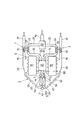
図1および図2は本発明の実施例1を示したもので、図1はターボ過給機付き多気筒内燃機関の排気ガス再循環装置の全体構成を示した図である。
[Configuration of Example 1]
1 and 2 show a first embodiment of the present invention, and FIG. 1 is a diagram showing an overall configuration of an exhaust gas recirculation device of a multi-cylinder internal combustion engine with a turbocharger.
本実施例のターボ過給機付き多気筒内燃機関の排気ガス再循環装置(以下排気ガス再循環装置と略す)は、複数のターボチャージャー(以下一対の第1、第2ターボ過給機と呼ぶ)1、2を備えたV型多気筒エンジン(ターボ過給機付き多気筒内燃機関:以下V型エンジンと呼ぶ)Eに使用されるもので、V型エンジンEの各気筒より排出される排気ガスの一部(排気再循環ガス:以下EGRガスと呼ぶ)を、V型エンジンEの複数の排気通路から複数の吸気通路に再循環(還流)させるための排気ガス還流管(EGRパイプ)3と、この排気ガス還流管3内を流れるEGRガスの還流量(排気ガス還流量、EGR量)を連続的または段階的に調整する複数の排気ガス還流量制御弁(以下一対の第1、第2EGR制御弁と呼ぶ)4、5とを備えている。そして、排気ガス還流管3には、一対の第1、第2EGR制御弁4、5よりもEGRガスの流れ方向の上流側に接続された排気ガス冷却装置(以下EGRガスクーラと呼ぶ)6、およびこのEGRガスクーラ6よりもEGRガスの流れ方向の上流側に接続された三方切替弁7とが設置されている。
An exhaust gas recirculation device (hereinafter abbreviated as an exhaust gas recirculation device) of a multi-cylinder internal combustion engine with a turbocharger according to the present embodiment is referred to as a plurality of turbochargers (hereinafter referred to as a pair of first and second turbochargers). ) Used for V-type multi-cylinder engine 1 and 2 (multi-cylinder internal combustion engine with turbocharger: hereinafter referred to as V-type engine) E, exhaust exhausted from each cylinder of V-type engine E An exhaust gas recirculation pipe (EGR pipe) 3 for recirculating (recirculating) a part of the gas (exhaust gas recirculation gas: hereinafter referred to as EGR gas) from a plurality of exhaust passages of the V-type engine E to a plurality of intake passages And a plurality of exhaust gas recirculation amount control valves (hereinafter referred to as a pair of first and second control valves) for adjusting the recirculation amount (exhaust gas recirculation amount, EGR amount) of the EGR gas flowing in the exhaust
ここで、V型エンジンEは、例えば自動車等の車両のエンジンルームに搭載されて、燃料が直接燃焼室内に噴射供給される直接噴射式ディーゼルエンジンである。そして、V型エンジンEは、気筒が群配置された複数のバンク(以下一対の第1、第2バンクと呼ぶ)11、12を有し、これらの第1、第2バンク11、12の各気筒がクランクシャフトを中心にしてV字型に配置されている。なお、気筒が群配置された複数のバンクを有する内燃機関としては、V型エンジンに限定されず、水平型エンジン、水平対向型エンジン等の多気筒エンジンを用いても良い。
Here, the V-type engine E is a direct-injection diesel engine that is mounted in an engine room of a vehicle such as an automobile and in which fuel is directly injected into the combustion chamber. The V-type engine E has a plurality of banks (hereinafter referred to as a pair of first and second banks) 11 and 12 in which cylinders are arranged in groups, and each of the first and
このV型エンジンEの第1バンク11の各気筒(シリンダ)には、各吸気ポートを開閉する吸気バルブ(図示せず)、および各排気ポートを開閉する排気バルブ(図示せず)が取り付けられている。また、第2バンク12の各気筒(シリンダ)には、第1バンク11と同様に、各吸気ポートを開閉する吸気バルブ(図示せず)、および各排気ポートを開閉する排気バルブ(図示せず)が取り付けられている。また、V型エンジンEは、一対の第1、第2バンク11、12毎に対応して接続される複数の吸気通路(以下一対の第1、第2吸気通路と呼ぶ)13、14、および一対の第1、第2バンク11、12毎に独立して接続される複数の排気通路(以下一対の第1、第2排気通路と呼ぶ)15、16を備えている。
An intake valve (not shown) for opening and closing each intake port and an exhaust valve (not shown) for opening and closing each exhaust port are attached to each cylinder (cylinder) of the
一対の第1、第2吸気通路13、14は、共通部19から吸い込んだ吸入空気を濾過するエアクリーナ20と、このエアクリーナ20で分岐されて、一対の第1、第2バンク11、12毎に独立して設けられる一対の第1、第2エンジン吸気管21、22と、これらの第1、第2エンジン吸気管21、22より流入する吸入空気が合流するサージタンク23と、このサージタンク23で分岐されて、一対の第1、第2バンク11、12毎に独立して設けられる一対の第1、第2インテークマニホールド(吸気多岐管)24、25とによって形成されている。また、一対の第1、第2排気通路15、16は、一対の第1、第2バンク11、12毎に独立して設けられる一対の第1、第2エキゾーストマニホールド(排気多岐管)29、30と、これらの第1、第2エキゾーストマニホールド29、30よりも下流側に接続される一対の第1、第2エンジン排気管31、32とによって形成されている。
The pair of first and
また、本実施例のV型エンジンEは、一対の第1、第2バンク11、12の各気筒より流出した排気ガスの排気エネルギーを利用して、V型エンジンEの全気筒の燃焼室内に吸入される吸入空気を過給する一対のターボ過給機1、2と、一対の第1、第2バンク11、12の各気筒より排出された排気ガスの一部をV型エンジンEの吸気側(本例ではサージタンク23)に再循環させる排気ガス再循環装置(EGR装置)とを備えている。
Further, the V-type engine E of the present embodiment uses the exhaust energy of the exhaust gas flowing out from the cylinders of the pair of first and
一対の第1、第2ターボ過給機1、2は、一対の第1、第2エンジン吸気管21、22の途中に設けられた第1、第2コンプレッサ33、34と、一対の第1、第2エンジン排気管31、32の途中に設けられた第1、第2タービン35、36とを備えている。そして、第1、第2コンプレッサ33、34および第1、第2タービン35、36には、それぞれ第1、第2タービン軸(ロータシャフト)37、38が組み付けられている。ここで、一対の第1、第2エンジン吸気管21、22の途中に、一対の第1、第2ターボ過給機1、2の第1、第2コンプレッサ33、34によって圧縮(過給)されて昇温した新規吸入空気を冷却するための空冷式または水冷式のインタークーラを設置しても良い。
The pair of first and second turbochargers 1 and 2 includes a first and
第1、第2コンプレッサ33、34は、第1、第2タービン軸37、38の中心軸線方向(軸方向)の一端部に取り付けられて、一対の第1、第2吸気通路13、14毎に対応して接続される複数のコンプレッサを構成している。これらの各第1、第2コンプレッサ33、34には、複数のコンプレッサブレードを有するコンプレッサホイールがそれぞれ設けられている。これらの各コンプレッサホイールは、一対の第1、第2エンジン吸気管21、22内を流れる吸入空気を過給するように、各コンプレッサハウジング内に回転自在に収容されている。なお、各コンプレッサハウジング内に形成される吸入空気供給経路は、各コンプレッサホイールの外周を囲むように、各コンプレッサホイールの回転方向に沿って渦巻き状に形成されている。
The first and
第1、第2タービン35、36は、第1、第2タービン軸37、38の軸方向の他端部に取り付けられて、一対の第1、第2排気通路15、16毎に対応して接続される複数のタービンを構成している。これらの各第1、第2タービン35、36には、複数のタービンブレードを有するタービンホイールがそれぞれ設けられている。これらの各タービンホイールは、一対の第1、第2エンジン排気管31、32内を流れる排気ガスによって回転するように、各タービンハウジング内に回転自在に収容されている。なお、各タービンハウジング内に形成される排気ガス排出経路は、各タービンホイールの外周を囲むように、各タービンホイールの回転方向に沿って渦巻き状に形成されている。
The first and
本実施例の排気ガス還流管3は、一対の第1、第2エキゾーストマニホールド29、30よりそれぞれ分岐する複数の排気ガス還流管(以下一対の第1、第2排気ガス還流管と呼ぶ)41、42、これらの第1、第2排気ガス還流管41、42の下流側端部が接続する合流管(合流部)43、およびこの合流管43より再度分岐する複数の排気ガス還流管(以下一対の第1、第2排気ガス還流管と呼ぶ)44、45を有し、EGRガスの流れ方向の下流端部が一対の第1、第2バンク共通のサージタンク23に接続している。一対の第1、第2排気ガス還流管41、42の内部には、一対の第1、第2排気通路15、16毎に独立して接続される複数の排気ガス還流路(以下一対の第1、第2排気ガス還流路と呼ぶ)51、52が形成されている。
The exhaust
合流管43は、三方管であって、内部に三方切替弁7を回転自在に収容するバルブ室を有している。また、合流管43には、第1排気ガス還流路51からバルブ室内にEGRガスを導入するための第1入口側ポート(第1排気導入孔)、第2排気ガス還流路52からバルブ室内にEGRガスを導入するための第2入口側ポート(第2排気導入孔)、およびバルブ室からEGRガスクーラ側にEGRガスを流出させるための出口側ポート(排気出口孔)が形成されている。
The
一対の第1、第2排気ガス還流管44、45の内部には、一対の第1、第2排気ガス還流管41、42毎に独立して接続される複数の排気ガス還流路(以下一対の第1、第2排気ガス還流路と呼ぶ)54、55が形成されている。また、一対の第1、第2排気ガス還流管44、45の下流側端部は、一対の第1、第2排気ガス還流路54、55からEGRガスを合流させた後にサージタンク23に流入させる集合流路(出口側流路)56とを備えている。なお、排気ガス還流管3の各第1、第2排気ガス還流管44、45の下流端部をサージタンク23(または第1、第2インテークマニホールド24、25)に直接接続しても良い。
Inside the pair of first and second exhaust
一対の第1、第2EGR制御弁4、5は、排気ガス還流管3の一対の第1、第2排気ガス還流管44、45の一部を成すハウジングと、このハウジングの内部に開閉自在に収容されたバルブ(ポペットバルブまたはバタフライバルブ:第1、第2EGR制御弁4、5の弁体)と、このバルブと一体的に直線運動または回転運動を行うバルブ軸(バルブシャフト)と、バルブを閉弁方向または開弁方向に付勢するスプリング等のバルブ付勢手段とをそれぞれ備えている。なお、各バルブを開弁駆動または閉弁駆動する複数のバルブ駆動装置は、電力によって運転される電動モータと、この電動モータの回転運動をバルブ軸に伝達するための動力伝達機構(例えば歯車減速機構)とを備えた電動式アクチュエータによって構成されている。ここで、複数のバルブ駆動装置、特に各電動モータは、エンジン制御ユニット(以下ECUと呼ぶ)によって通電制御されるように構成されている。
The pair of first and second
また、ハウジングの内部には、一対の第1、第2排気ガス還流路54、55がそれぞれ形成されており、一対の第1、第2EGR制御弁4、5の各バルブは、それぞれに対応する第1、第2排気ガス還流路54、55の開口面積を変更することが可能なようにハウジングの内部に配設されている。また、ハウジングの内部には、各バルブ軸をブッシングやボールベアリング(軸受部品)、オイルシールを介して、摺動自在または回転自在に軸支するバルブ軸受部が一体的に形成されている。なお、オイルシールは、ハウジングのバルブ軸受部を潤滑する潤滑油が第1、第2EGR制御弁4、5のバルブ側に流出するのを防止するシールゴム等である。また、ハウジングのバルブ軸受部を介して、ハウジングの内部(第1、第2連通路)からハウジングの外部に排気ガスが漏洩するのを防止するシールゴム等のパッキンを設置しても良い。なお、内部に第1、第2排気ガス還流路54、55を形成するハウジングを1個のハウジングによって構成しても構わないし、内部に各第1、第2排気ガス還流路54、55を形成するハウジングを複数個のハウジングによって構成しても構わない。
In addition, a pair of first and second exhaust
EGRガスクーラ6は、一対の第1、第2排気ガス還流管44、45よりもEGRガスの流れ方向の上流側(合流管側)設置されて、入口側タンク部が合流管43の出口側ポートに直接接続している。そして、EGRガスクーラ6は、合流管43のバルブ室を介して、各第1、第2排気ガス還流路51、52から導入される高温のEGRガスと低温のエンジン冷却水とを熱交換させることで、EGRガスを所望の排気温度以下に冷却する水冷式の排気熱交換器である。
The
このEGRガスクーラ6は、排気ガス還流管3の途中、すなわち、合流管43の出口側ポートと一対の第1、第2排気ガス還流管44、45の上流側端部との間に直列的に直接結合されるケーシング(図示せず)を有している。このケーシングの上流端部には、仕切り板により複数(本例では2つ)の入口側タンク室に区画された入口側タンク部が設けられ、また、ケーシングの下流端部には、仕切り板により複数(本例では2つ)の出口側タンク室に区画された出口側タンク部が設けられている。そして、入口側タンク部と出口側タンク部との間には、複数の排気チューブ(図示せず)が接続され、これらの排気チューブは、ケーシングの内部に収容されている。また、ケーシングの内部には、複数の排気チューブの周囲にエンジン冷却水が循環する冷却水流路(図示せず)が形成されている。
This
複数の排気チューブは、2本以上の第1排気チューブ群と、これらの第1排気チューブ群に並列して配置される2本以上の第2排気チューブ群とによって構成されている。そして、第1排気チューブ群を構成する各排気チューブの内部には、複数の入口側タンク室のうちの一方の入口側タンク室を介して、合流管43の出口側ポートから流入する高温のEGRガスを、冷却水流路内を流れるエンジン冷却水と熱交換させて冷却する第1排気ガス冷却流路61が形成されている。この第1排気ガス冷却流路61の下流端部は、複数の出口側タンク室のうちの一方の出口側タンク室を介して、第1排気ガス還流路54に連通している。
The plurality of exhaust tubes are constituted by two or more first exhaust tube groups and two or more second exhaust tube groups arranged in parallel with these first exhaust tube groups. And inside each exhaust tube which comprises the 1st exhaust tube group, the high temperature EGR which flows in from the exit side port of the
また、第2排気チューブ群を構成する各排気チューブの内部には、複数の入口側タンク室のうちの他方の入口側タンク室を介して、合流管43の出口側ポートから流入する高温のEGRガスを、冷却水流路内を流れるエンジン冷却水と熱交換させて冷却する第2排気ガス冷却流路62が形成されている。この第2排気ガス冷却流路62の下流端部は、複数の出口側タンク室のうちの他方の出口側タンク室を介して、第2排気ガス還流路55に連通している。ここで、複数の入口側タンク室、第1、第2排気ガス冷却流路61、62、複数の出口側タンク室は、一対の第1、第2排気ガス還流路54、55毎に対応して接続する複数の排気ガス冷却流路を構成する。
Further, inside each exhaust tube constituting the second exhaust tube group, high-temperature EGR flowing from the outlet side port of the
なお、複数の排気チューブの内部には、EGRガスとの伝熱面積を増加してEGRガスとエンジン冷却水との熱交換効率を向上させるための矩形波状のインナーフィン(図示せず)が配設されている。また、ケーシング、複数の排気チューブおよびインナーフィンは、硫化物、硝酸、硫酸、アンモニウムイオン、酢酸等を含む400〜500℃以上の高温EGRガスおよびその凝縮水に排気ガス冷却流路側が晒されるので、耐熱性および耐腐食性に優れた金属材料(例えばステンレス鋼)を一体ろう付け接合することによって製造され、EGRガスクーラ6が一体化されている。
Inside the plurality of exhaust tubes, rectangular wave-shaped inner fins (not shown) for increasing the heat transfer area with the EGR gas and improving the heat exchange efficiency between the EGR gas and the engine coolant are arranged. It is installed. Further, the casing, the plurality of exhaust tubes, and the inner fin are exposed to the high temperature EGR gas at 400 to 500 ° C. or higher containing sulfide, nitric acid, sulfuric acid, ammonium ions, acetic acid, and the like, and the exhaust gas cooling channel side thereof. The
ここで、本実施例のV型エンジンEには、EGRガスクーラ6にエンジン冷却水を循環供給するためのエンジン冷却水回路(冷却水循環路)が設けられている。このエンジン冷却水回路は、V型エンジンEのウォータジャケット(図示せず)からEGRガスクーラ6の冷却水入口部へエンジン冷却水を循環供給するための冷却水配管(図示せず)と、EGRガスクーラ6の冷却水出口部からラジエータ(図示せず)を経てV型エンジンEのウォータジャケットにエンジン冷却水を循環供給する(戻す)ための冷却水配管(図示せず)と、エンジン冷却水回路中にエンジン冷却水の循環流を発生させるウォータポンプ(図示せず)とを備えている。なお、本実施例では、ラジエータでエンジン冷却水と室外空気(外気)とを熱交換させることで、所定の温度範囲(例えば75〜80℃)のエンジン冷却水をV型エンジンEのウォータジャケットに戻すように構成されている。
Here, the V-type engine E of the present embodiment is provided with an engine cooling water circuit (cooling water circulation path) for circulatingly supplying engine cooling water to the
また、排気ガス還流管3の一対の第1、第2排気ガス還流管41、42の下流側端部とEGRガスクーラ6の入口部(複数の入口側タンク部)との間に設けられる合流管43のバルブ室の内部には、三方切替弁7が回転自在に収容されている。この三方切替弁7は、排気ガス還流管3の一部を成すハウジングと、このハウジングの内部(合流管43のバルブ室)に回転自在に収容されたロータリー型のバルブ(三方切替弁7の弁体)と、このバルブと一体的に回転運動を行うバルブ軸(バルブシャフト)とを備えている。なお、バルブを回転駆動するバルブ駆動装置は、電力によって運転される電動モータ、およびこの電動モータの回転運動をバルブ軸に伝達するための動力伝達機構(例えば歯車減速機構)等によって構成されている。ここで、バルブ駆動装置、特に電動モータは、ECUによって通電制御されるように構成されている。
Further, a merging pipe provided between the downstream end of the pair of first and second exhaust
ここで、三方切替弁7の構成要素の1つであるハウジングは、EGRガスクーラ6の入口部よりも排気ガスの流れ方向の上流側に設置されている。また、三方切替弁7の構成要素の1つであるバルブは、ハウジングの内部(バルブ室)を3つの空間に仕切るY字型の回転弁が用いられている。また、三方切替弁7は、一対の第1、第2EGR制御弁4、5が共に非作動時、つまり一対の第1、第2EGR制御弁4、5が共に全閉状態の時に、排気ガス還流管3の一対の第1、第2排気ガス還流管41、42内に形成される各第1、第2排気ガス還流路51、52の下流側端部同士の連通状態を遮断する還流路遮断弁を構成している。
Here, the housing, which is one of the components of the three-
そして、三方切替弁7は、一対の第1、第2EGR制御弁4、5が共に非作動時、つまり一対の第1、第2EGR制御弁4、5が共に全閉状態の時に、一対の第1、第2排気ガス還流路51、52の下流側端部同士の連通状態を遮断する遮断状態(第1切替モード:図1参照)と、一対の第1、第2EGR制御弁4、5が共に作動時、つまり一対の第1、第2EGR制御弁4、5が共に半開弁状態および全開状態の時に、一対の第1、第2排気ガス還流路51、52の下流側端部とEGRガスクーラ6の入口部(複数の入口側タンク部)とを連通する連通状態(第2切替モード:図2参照)とを切り替える。
The three-
ここで、ECUには、制御処理、演算処理を行うCPU、各種プログラムおよびデータを保存する記憶装置(ROMやRAM等のメモリ)、入力回路、出力回路等の機能を含んで構成される周知の構造のマイクロコンピュータが設けられている。また、ECUは、図示しないイグニッションスイッチをオン(IG・ON)すると、メモリ内に格納された制御プログラムに基づいて、一対の第1、第2EGR制御弁4、5の弁開度および三方切替弁7の制御位置を電子制御するように構成されている。なお、ECUは、イグニッションスイッチがオフ(IG・OFF)されると、メモリ内に格納された制御プログラムに基づく上記の制御が強制的に終了されるように構成されている。そして、各種センサからのセンサ信号は、A/D変換器でA/D変換された後に、ECUに内蔵されたマイクロコンピュータに入力されるように構成されている。そして、マイクロコンピュータには、EGR量センサ、クランク角度センサ、アクセル開度センサ、エアフロメータおよび冷却水温度センサ等が接続されている。
Here, the ECU includes a CPU that performs control processing, arithmetic processing, a storage device (memory such as ROM and RAM) that stores various programs and data, an input circuit, an output circuit, and the like. A microcomputer having a structure is provided. Further, when an ignition switch (not shown) is turned on (IG / ON), the ECU opens and opens the pair of first and second
[実施例1の作用]
次に、本実施例の排気ガス再循環装置の作用を図1および図2に基づいて簡単に説明する。
[Operation of Example 1]
Next, the operation of the exhaust gas recirculation device of this embodiment will be briefly described with reference to FIGS.
V型エンジンEが始動することにより、V型エンジンEの第1、第2バンク11、12の各気筒の吸気ポートが開かれると、エアクリーナ20で濾過された吸入空気が一対の第1、第2吸気通路13、14に分配して流れ、V型エンジンEの第1、第2バンク11、12の各気筒内に吸入される。そして、V型エンジンEでは、燃料が燃える温度よりも高い温度になるまで空気を圧縮し、そこに燃料を噴霧して燃焼が成される。そして、V型エンジンEの第1、第2バンク11、12の各気筒内で燃えた燃焼ガスは、各排気ポートから排出され、一対の第1、第2排気通路15、16を経て排出される。
When the intake port of each cylinder of the first and
このとき、一対の第1、第2ターボ過給機1、2は、一対の第1、第2エンジン排気管31、32内に形成される各第1、第2排気通路15、16を流れる排気ガスの排気エネルギーを利用して各第1、第2タービン35、36が回転駆動される。そして、各第1、第2タービン35、36に各第1、第2タービン軸37、38を介して連結された各第1、第2コンプレッサ33、34が回転駆動される。これにより、第1、第2吸気通路13、14を通過する吸入空気が過給されて、V型エンジンEの第1、第2バンク11、12の各気筒内に吸入される。
At this time, the pair of first and second turbochargers 1 and 2 flows through the first and
このとき、ECUは、エンジン回転速度およびエンジン負荷(例えばアクセル開度)に応じて、一対の第1、第2EGR制御弁4、5の弁開度および三方切替弁7の制御位置を制御する。ここで、一対の第1、第2EGR制御弁4、5は、高負荷領域では全閉状態とされ、また、低負荷領域および中負荷領域では全開状態または半開弁状態とされる。そして、三方切替弁7は、高負荷領域では一対の第1、第2排気ガス還流路51、52の下流側端部同士の連通状態を遮断する遮断状態(第1切替モード:図1参照)とされ、また、低負荷領域および中負荷領域では一対の第1、第2排気ガス還流路51、52の下流側端部とEGRガスクーラ6の入口部(複数の入口側タンク部)とを連通する連通状態(第2切替モード:図2参照)とされる。
At this time, the ECU controls the valve openings of the pair of first and second
したがって、低負荷領域および中負荷領域では、一対の第1、第2EGR制御弁4、5が全開状態または半開弁状態とされ、三方切替弁7が第2切替モードに切り替えられるので、図2に示したように、V型エンジンEの第1、第2バンク11、12毎に独立して接続された第1、第2エキゾーストマニホールド29、30内に形成される各第1、第2排気通路15、16から排気ガス還流管3の一対の第1、第2排気ガス還流管41、42内に形成される各第1、第2排気ガス還流路51、52、合流管43のバルブ室を通ってEGRガスクーラ6の内部にEGRガスが流入する。
Therefore, in the low load region and the medium load region, the pair of first and second
そして、EGRガスクーラ6の内部に流入したEGRガスは、各第1、第2排気ガス冷却流路61、62を通過する際に、冷却水流路内を循環するエンジン冷却水によって十分に冷却された後に、排気ガス還流管3の一対の第1、第2排気ガス還流管44、45内に形成される各第1、第2排気ガス還流路54、55を通って第1、第2EGR制御弁4、5の内部に流入する。そして、第1、第2EGR制御弁4、5から流出したEGRガスは、一対の第1、第2排気ガス還流管44、45内に形成される各第1、第2排気ガス還流路54、55、集合流路(出口側流路)56を通って、V型エンジンEの第1、第2バンク共通のサージタンク23に流れ込む。これによって、温度が低く、体積の小さい低温のEGRガスが吸入空気と混入し、更に第1、第2EGR制御弁4、5の弁開度を調整することで所望のEGR率を確保できるので、V型エンジンEの出力を低下させることなく、燃焼温度を低下して効果的にNOxの発生を低減させることができる。
The EGR gas that has flowed into the
また、高負荷領域では、一対の第1、第2EGR制御弁4、5が全閉状態とされ、三方切替弁7が第1切替モードに切り替えられるので、図1に示したように、排気ガス還流管3の一対の第1、第2排気ガス還流管44、45内に形成される各第1、第2排気ガス還流路51、52の下流側端部同士が気密的に遮断される。これにより、V型エンジンEの第1、第2バンク11、12毎に独立して接続された第1、第2エキゾーストマニホールド29、30内に形成される各第1、第2排気通路15、16で発生する排気脈動圧が互いに影響を受けなくなる。
Further, in the high load region, the pair of first and second
[実施例1の効果]
本実施例の排気ガス再循環装置においては、排気ガス還流管3の一対の第1、第2排気ガス還流管41、42の下流側端部とEGRガスクーラ6の入口部との間に設けられる合流管43のバルブ室の内部に三方切替弁7を設置しているので、V型エンジンEの第1、第2バンク11、12毎に発生した排気脈動圧が、図1に示したように仮に逆位相であっても干渉することはなく、V型エンジンEの第1、第2バンク11、12毎に発生した排気脈動圧が互いに影響を受けなくなる。これによって、V型エンジンEの第1、第2バンク11、12毎に独立して接続される一対のターボ過給機1、2の各第1、第2タービン35、36が排気脈動圧の影響を受けない配管レイアウトとなるので、一対の第1、第2ターボ過給機1、2の各第1、第2タービン35、36に作用する排気圧力が高くなり、過給効率の高い運転状態を維持できる。そして、一対の第1、第2ターボ過給機1、2の過給効率に応じて吸入空気の充填効率も高くなり、それに伴い排気ガス量が増加して排気圧力が更に高くなるので、一対の第1、第2ターボ過給機1、2の過給効率が更に向上する。したがって、吸入空気の充填効率の向上および一対の第1、第2ターボ過給機1、2の過給効率の向上を図ることができる。
[Effect of Example 1]
In the exhaust gas recirculation apparatus of the present embodiment, the exhaust
また、一対の第1、第2EGR制御弁4、5よりもEGRガスの流れ方向の上流側に、V型エンジンEの第1、第2バンク11、12毎に独立して接続された一対の第1、第2排気通路15、16から排気ガス還流管3の一対の第1、第2排気ガス還流管41、42内に形成される各第1、第2排気ガス還流路51、52、合流管43のバルブ室を経由して流入したEGRガスをエンジン冷却水を利用して冷却するEGRガスクーラ6を設置している。これによって、低負荷領域および中負荷領域の時に、一対の第1、第2EGR制御弁4、5を全開状態または半開弁状態とし、また、三方切替弁7を第2切替モードに切り替えることにより、EGRガスクーラ6の各第1、第2排気ガス冷却流路61、62を通過する際に、冷却水流路内を循環するエンジン冷却水によって十分に冷却された低温のEGRガスがV型エンジンEの第1、第2バンク11、12の吸気側(サージタンク23)に再循環(還流)される。これにより、吸入空気の充填効率が向上するので、V型エンジンEの各第1、第2バンク11、12毎の気筒内における混合気の燃焼が改善されてV型エンジンEの出力が向上する。
Further, a pair of independently connected each of the first and
また、一対の第1、第2EGR制御弁4、5よりもEGRガスの流れ方向の上流側に、各第1、第2EGR制御弁4、5に向かうEGRガスを冷却するEGRガスクーラ6を設置している。これによって、高温のEGRガスの熱が、一対の第1、第2EGR制御弁4、5のハウジングのバルブ軸受部側に伝わり難くなり、ハウジングのバルブ軸受部の熱影響を減らすことが可能となる。特に、一対の第1、第2EGR制御弁4、5のハウジングのバルブ軸受部とバルブ軸との間にシールゴム等のオイルシールまたはシールゴム等のパッキンを設けた場合には、オイルシールまたはパッキンが高温のEGRガスの熱により劣化するのを抑えることができる。したがって、一対の第1、第2EGR制御弁4、5の内蔵部品(オイルシールまたはパッキン等のゴム製品)の耐熱性の向上を図ることができる。
Further, an
[変形例]
本実施例では、一対の第1、第2EGR制御弁4、5のバルブを開弁駆動または閉弁駆動するバルブ駆動装置を、電動モータと動力伝達機構(例えば歯車減速機構等)とを備えた電動式アクチュエータによって構成したが、一対の第1、第2EGR制御弁4、5のバルブを開弁駆動(または閉弁駆動)するバルブ駆動装置を、電磁式または電動式負圧制御弁を備えた負圧作動式アクチュエータや、電磁式流量制御弁等の電磁式アクチュエータによって構成しても良い。また、三方切替弁7のバルブ駆動装置を、電磁式または電動式負圧制御弁を備えた負圧作動式アクチュエータや、電磁式流路切替弁等の電磁式アクチュエータによって構成しても良い。
[Modification]
In this embodiment, the valve driving device for opening or closing the pair of first and second
本実施例では、EGRガスクーラ6のみによって排気ガス冷却装置を構成しているが、EGRガスクーラ6と、このEGRガスクーラ6内に形成される排気ガス冷却流路を迂回するバイパス流路を有するバイパス配管とによって排気ガス冷却装置を構成しても良い。また、本実施例では、還流路遮断弁として、排気ガス還流管3の合流管43のバルブ室内に回転自在に収容された三方切替弁7を用いたが、還流路遮断弁として、排気ガス還流管3の一対の第1、第2排気ガス還流管41、42内に形成される各第1、第2排気ガス還流路51、52のうちの少なくとも一方の排気ガス還流路を開閉する開閉弁を用いても良い。この場合には、開閉弁の駆動装置を、電動式アクチュエータ、負圧作動式アクチュエータ、電磁式アクチュエータによって構成しても良い。
In the present embodiment, the exhaust gas cooling device is configured only by the
本実施例では、排気ガス還流量制御弁を、複数の排気ガス還流量制御弁(一対の第1、第2EGR制御弁4、5)によって構成しているが、排気ガス還流量制御弁を、1個の排気ガス還流量制御弁(EGR制御弁)によって構成しても良く、また、3個以上の排気ガス還流量制御弁(EGR制御弁)によって構成しても良い。また、排気ガス還流管3の一対の第1、第2排気ガス還流管44、45を1本または3本以上の排気ガス還流管によって構成しても良い。さらに、本実施例では、排気ガス冷却装置を、一対の排気ガス冷却流路61、62を有するEGRガスクーラ6によって構成しているが、排気ガス冷却装置を、合流部より排気ガスの全量が導入される複数の排気ガス冷却流路を有するEGRガスクーラによって構成しても良い。また、EGRガスクーラを2分割以上のセパレートタイプとしても良い。
In this embodiment, the exhaust gas recirculation amount control valve is constituted by a plurality of exhaust gas recirculation amount control valves (a pair of first and second
E V型エンジン(内燃機関)
1 第1ターボ過給機
2 第2ターボ過給機
3 排気ガス還流管
4 第1EGR制御弁(排気ガス還流量制御弁)
5 第2EGR制御弁(排気ガス還流量制御弁)
6 EGRガスクーラ(排気ガス冷却装置)
7 三方切替弁(還流路遮断弁)
11 第1バンク
12 第2バンク
13 第1吸気通路
14 第2吸気通路
15 第1排気通路
16 第2排気通路
33 第1ターボ過給機の第1コンプレッサ
34 第2ターボ過給機の第2コンプレッサ
35 第1ターボ過給機の第1タービン
36 第2ターボ過給機の第2タービン
41 第1排気ガス還流管
42 第2排気ガス還流管
43 合流管(合流部)
44 第1排気ガス還流管
45 第2排気ガス還流管
51 第1排気ガス還流路
52 第2排気ガス還流路
54 第1排気ガス還流路
55 第2排気ガス還流路
61 EGRガスクーラの第1排気ガス冷却流路
62 EGRガスクーラの第2排気ガス冷却流路
EV type engine (internal combustion engine)
DESCRIPTION OF SYMBOLS 1 1st turbocharger 2
5 Second EGR control valve (exhaust gas recirculation amount control valve)
6 EGR gas cooler (exhaust gas cooling device)
7 Three-way switching valve (reflux passage shut-off valve)
DESCRIPTION OF
44 First exhaust
Claims (6)
(b)前記複数の排気通路毎に対応して接続される複数のタービンを有し、
前記複数のバンクの気筒より流出した排気ガスの排気エネルギーを利用して、前記内燃機関の気筒内に吸入される吸入空気を過給する複数のターボ過給機と、
(c)前記複数の排気通路毎に独立して接続される複数の排気ガス還流路を有し、
前記内燃機関の複数のバンク毎より流出した排気ガスの一部を、前記複数の排気通路から前記内燃機関の吸気側に還流させる排気ガス還流管と、
(d)この排気ガス還流管に開閉自在に設置されて、前記内燃機関の吸気側に還流する排気ガス還流量を調整する排気ガス還流量制御弁と
を備えた過給機付き内燃機関の排気ガス再循環装置において、
前記排気ガス還流管は、
前記排気ガス還流量制御弁よりも排気ガスの流れ方向の上流側に設置されて、前記複数のバンクの気筒から流入した排気ガスを冷却する排気ガス冷却装置と、
この排気ガス冷却装置よりも排気ガスの流れ方向の上流側に設置されて、前記排気ガス還流量制御弁が全閉状態の時に前記複数の排気ガス還流路の連通状態を遮断する還流路遮断弁と
を備えたことを特徴とする過給機付き内燃機関の排気ガス再循環装置。 (A) an internal combustion engine having a plurality of banks each having at least one or more cylinders disposed therein, and a plurality of exhaust passages connected independently for each bank;
(B) having a plurality of turbines connected corresponding to each of the plurality of exhaust passages;
A plurality of turbochargers that supercharge intake air drawn into the cylinders of the internal combustion engine using exhaust energy of exhaust gas flowing out from the cylinders of the plurality of banks;
(C) having a plurality of exhaust gas recirculation paths connected independently for each of the plurality of exhaust passages;
An exhaust gas recirculation pipe for recirculating a part of the exhaust gas flowing out from each bank of the internal combustion engine to the intake side of the internal combustion engine from the plurality of exhaust passages;
(D) Exhaust of an internal combustion engine with a supercharger, which is installed in the exhaust gas recirculation pipe so as to be freely opened and closed, and has an exhaust gas recirculation amount control valve for adjusting an exhaust gas recirculation amount that recirculates to the intake side of the internal combustion engine. In the gas recirculation device,
The exhaust gas recirculation pipe is
An exhaust gas cooling device that is disposed upstream of the exhaust gas recirculation amount control valve in the exhaust gas flow direction and cools the exhaust gas flowing in from the cylinders of the plurality of banks;
A reflux path shut-off valve that is installed upstream of the exhaust gas cooling device in the exhaust gas flow direction and shuts off the communication state of the plurality of exhaust gas reflux paths when the exhaust gas recirculation amount control valve is in a fully closed state. An exhaust gas recirculation device for an internal combustion engine with a supercharger.
前記複数のバンクは、前記気筒が群配置された一対の第1、第2バンクを有し、
前記複数の排気通路は、前記一対の第1、第2バンクの各気筒毎に対応して接続される一対の第1、第2排気通路を有し、
前記複数の排気ガス還流路は、前記一対の第1、第2排気通路毎に対応して接続される一対の第1、第2排気ガス還流路を有していることを特徴とする過給機付き内燃機関の排気ガス再循環装置。 The exhaust gas recirculation device for an internal combustion engine with a supercharger according to claim 1,
The plurality of banks have a pair of first and second banks in which the cylinders are arranged in groups,
The plurality of exhaust passages have a pair of first and second exhaust passages connected corresponding to each cylinder of the pair of first and second banks,
The plurality of exhaust gas recirculation paths have a pair of first and second exhaust gas recirculation paths connected corresponding to the pair of first and second exhaust paths. Exhaust gas recirculation device for internal combustion engine with a machine.
前記排気ガス還流管は、前記第1排気ガス還流路から前記排気ガス冷却装置側に向かう排気ガスと、前記第2排気ガス還流路から前記排気ガス冷却装置側に向かう排気ガスとを合流させる合流部を有していることを特徴とする過給機付き内燃機関の排気ガス再循環装置。 The exhaust gas recirculation device for an internal combustion engine with a supercharger according to claim 2,
The exhaust gas recirculation pipe joins the exhaust gas from the first exhaust gas recirculation path toward the exhaust gas cooling device and the exhaust gas from the second exhaust gas recirculation path toward the exhaust gas cooling device. The exhaust-gas recirculation apparatus of the internal combustion engine with a supercharger characterized by having a part.
前記還流路遮断弁は、前記一対の第1、第2排気ガス還流路を連通させる連通状態と前記一対の第1、第2排気ガス還流路を遮断する遮断状態とを選択的に切り替える切替弁であることを特徴とする過給機付き内燃機関の排気ガス再循環装置。 The exhaust gas recirculation device for an internal combustion engine with a supercharger according to claim 3,
The recirculation path shut-off valve is a switching valve that selectively switches between a communication state in which the pair of first and second exhaust gas recirculation paths are in communication and a shut-off state in which the pair of first and second exhaust gas recirculation paths is shut off. An exhaust gas recirculation device for an internal combustion engine with a supercharger, characterized in that:
前記還流路遮断弁は、前記一対の第1、第2排気ガス還流路のうちの少なくとも一方の排気ガス還流路を開閉する開閉弁であることを特徴とする過給機付き内燃機関の排気ガス再循環装置。 The exhaust gas recirculation device for an internal combustion engine with a supercharger according to claim 3,
The exhaust gas of an internal combustion engine with a supercharger, wherein the reflux path shut-off valve is an on-off valve that opens and closes at least one exhaust gas reflux path of the pair of first and second exhaust gas reflux paths. Recirculation device.
前記排気ガス還流量制御弁は、前記排気ガス還流管の一部を成すハウジングと、このハウジングの内部に開閉自在に収容されたバルブと、このバルブと一体的に動作するバルブ軸とを備え、
前記ハウジングは、前記バルブ軸を摺動自在または回転自在に軸支するバルブ軸受部を有していることを特徴とする過給機付き内燃機関の排気ガス再循環装置。
The exhaust gas recirculation device for an internal combustion engine with a supercharger according to any one of claims 1 to 5,
The exhaust gas recirculation amount control valve includes a housing that forms a part of the exhaust gas recirculation pipe, a valve that is housed in the housing so as to be openable and closable, and a valve shaft that operates integrally with the valve.
The exhaust gas recirculation device for an internal combustion engine with a supercharger, wherein the housing has a valve bearing portion that rotatably or rotatably supports the valve shaft.
Priority Applications (4)
| Application Number | Priority Date | Filing Date | Title |
|---|---|---|---|
| JP2005223607A JP2007040136A (en) | 2005-08-02 | 2005-08-02 | Exhaust gas recirculation device for an internal combustion engine with a supercharger |
| US11/489,439 US20070028901A1 (en) | 2005-08-02 | 2006-07-20 | Exhaust gas recirculation system for internal combustion engine having superchargers |
| FR0606837A FR2889563A1 (en) | 2005-08-02 | 2006-07-26 | EXHAUST GAS RECYCLING SYSTEM FOR INTERNAL COMBUSTION ENGINE HAVING EXHAUST COMPRESSORS |
| DE102006000383A DE102006000383A1 (en) | 2005-08-02 | 2006-08-01 | Exhaust gas recirculation system for an internal combustion engine with charging devices |
Applications Claiming Priority (1)
| Application Number | Priority Date | Filing Date | Title |
|---|---|---|---|
| JP2005223607A JP2007040136A (en) | 2005-08-02 | 2005-08-02 | Exhaust gas recirculation device for an internal combustion engine with a supercharger |
Publications (1)
| Publication Number | Publication Date |
|---|---|
| JP2007040136A true JP2007040136A (en) | 2007-02-15 |
Family
ID=37669699
Family Applications (1)
| Application Number | Title | Priority Date | Filing Date |
|---|---|---|---|
| JP2005223607A Pending JP2007040136A (en) | 2005-08-02 | 2005-08-02 | Exhaust gas recirculation device for an internal combustion engine with a supercharger |
Country Status (4)
| Country | Link |
|---|---|
| US (1) | US20070028901A1 (en) |
| JP (1) | JP2007040136A (en) |
| DE (1) | DE102006000383A1 (en) |
| FR (1) | FR2889563A1 (en) |
Cited By (6)
| Publication number | Priority date | Publication date | Assignee | Title |
|---|---|---|---|---|
| JP2010065601A (en) * | 2008-09-10 | 2010-03-25 | Fuji Heavy Ind Ltd | Exhaust gas recirculating device of diesel engine |
| JP2011106369A (en) * | 2009-11-18 | 2011-06-02 | Toyota Motor Corp | Internal combustion engine |
| CN103511133A (en) * | 2012-06-25 | 2014-01-15 | 通用汽车环球科技运作有限责任公司 | Engine including low pressure EGR system and internal EGR |
| JP5692235B2 (en) * | 2010-11-19 | 2015-04-01 | トヨタ自動車株式会社 | Control device for internal combustion engine |
| JP2018096297A (en) * | 2016-12-14 | 2018-06-21 | いすゞ自動車株式会社 | Internal combustion engine intake and exhaust structure |
| KR20220138407A (en) * | 2020-02-18 | 2022-10-12 | 인니오 워케샤 가스 엔진스 인크. | Systems and methods for management of a plurality of exhaust gas recirculation coolers |
Families Citing this family (26)
| Publication number | Priority date | Publication date | Assignee | Title |
|---|---|---|---|---|
| JP4300364B2 (en) * | 2004-09-29 | 2009-07-22 | 日産自動車株式会社 | Supercharging pressure regulator for variable supercharging system |
| JP4461074B2 (en) * | 2005-07-14 | 2010-05-12 | 株式会社豊田自動織機 | Exhaust gas purification device in internal combustion engine |
| US7740007B2 (en) * | 2006-09-07 | 2010-06-22 | Ford Global Technologies, Llc | Alternative left/right bank EGR loop operation to improve fouling resistance during low mass flow engine mode |
| WO2008129404A2 (en) * | 2007-04-18 | 2008-10-30 | Continental Automotive Canada Inc. | Dual exhaust gas recirculation valve |
| US20090260605A1 (en) * | 2007-11-01 | 2009-10-22 | Cummins Intellectual Properties, Inc. | Staged arrangement of egr coolers to optimize performance |
| US20090139500A1 (en) * | 2007-12-03 | 2009-06-04 | International Engine Intellectual Property Company, Llc | Exhaust gas recirculation system |
| FR2926113A1 (en) * | 2008-01-03 | 2009-07-10 | Valeo Sys Controle Moteur Sas | EGR LOOP OF AN INTERNAL COMBUSTION ENGINE OF A MOTOR VEHICLE |
| WO2010008961A2 (en) * | 2008-07-16 | 2010-01-21 | Borgwarner Inc. | Diagnosing a cooling subsystem of an engine system in response to dynamic pressure sensed in the subsystem |
| US8176737B2 (en) * | 2008-07-31 | 2012-05-15 | Caterpillar Inc. | Exhaust system having 3-way valve |
| US8196403B2 (en) * | 2008-07-31 | 2012-06-12 | Caterpillar Inc. | Turbocharger having balance valve, wastegate, and common actuator |
| US8161747B2 (en) | 2008-07-31 | 2012-04-24 | Caterpillar Inc. | Exhaust system having series turbochargers and EGR |
| US8297053B2 (en) * | 2008-07-31 | 2012-10-30 | Caterpillar Inc. | Exhaust system having parallel asymmetric turbochargers and EGR |
| DE102008048681B4 (en) * | 2008-09-24 | 2019-08-08 | Audi Ag | Internal combustion engine with two loaders and method for operating the same |
| DE102010036946A1 (en) * | 2010-08-11 | 2012-02-16 | Ford Global Technologies, Llc. | High pressure exhaust gas recirculation system with heat recovery |
| US8944034B2 (en) * | 2011-02-11 | 2015-02-03 | Southwest Research Institute | Dedicated EGR control strategy for improved EGR distribution and engine performance |
| JP2013167166A (en) * | 2012-02-14 | 2013-08-29 | Aisan Industry Co Ltd | Exhaust gas recirculation apparatus for engine |
| US9657689B2 (en) * | 2012-05-10 | 2017-05-23 | International Engine Intellectual Property Comapny, LLC. | Modulating bypass valve |
| US9169794B2 (en) * | 2012-12-10 | 2015-10-27 | Caterpillar Inc. | Temperature-controlled exhaust gas recirculation system and method for dual fuel engine |
| US9243547B2 (en) * | 2014-02-13 | 2016-01-26 | Ford Global Technologies, Llc | Dual inlet and outlet exhaust gas recirculation cooler for turbocharged engine |
| US10233809B2 (en) | 2014-09-16 | 2019-03-19 | Southwest Research Institute | Apparatus and methods for exhaust gas recirculation for an internal combustion engine powered by a hydrocarbon fuel |
| US10125726B2 (en) | 2015-02-25 | 2018-11-13 | Southwest Research Institute | Apparatus and methods for exhaust gas recirculation for an internal combustion engine utilizing at least two hydrocarbon fuels |
| US9797349B2 (en) | 2015-05-21 | 2017-10-24 | Southwest Research Institute | Combined steam reformation reactions and water gas shift reactions for on-board hydrogen production in an internal combustion engine |
| US9657692B2 (en) | 2015-09-11 | 2017-05-23 | Southwest Research Institute | Internal combustion engine utilizing two independent flow paths to a dedicated exhaust gas recirculation cylinder |
| US9874193B2 (en) | 2016-06-16 | 2018-01-23 | Southwest Research Institute | Dedicated exhaust gas recirculation engine fueling control |
| US10495035B2 (en) | 2017-02-07 | 2019-12-03 | Southwest Research Institute | Dedicated exhaust gas recirculation configuration for reduced EGR and fresh air backflow |
| WO2020200448A1 (en) * | 2019-04-04 | 2020-10-08 | Volvo Truck Corporation | An internal combustion engine system and a method of operating an internal combustion system |
Family Cites Families (8)
| Publication number | Priority date | Publication date | Assignee | Title |
|---|---|---|---|---|
| US4496291A (en) * | 1981-11-13 | 1985-01-29 | Grimmer John E | Compound turbocharger system for an internal combustion engine |
| DE19618868C2 (en) * | 1996-05-10 | 1998-07-02 | Daimler Benz Ag | Internal combustion engine with an exhaust gas recirculation system |
| DE19835978C1 (en) * | 1998-08-08 | 1999-11-25 | Daimler Chrysler Ag | Motor vehicle twin turbocharger internal combustion engine with exhaust gas recycling |
| US6089019A (en) * | 1999-01-15 | 2000-07-18 | Borgwarner Inc. | Turbocharger and EGR system |
| DE19960998C1 (en) * | 1999-12-17 | 2001-02-15 | Mtu Friedrichshafen Gmbh | Exhaust gas recycling device, with self-operating no-return valve in exhaust gas collector line |
| US6408833B1 (en) * | 2000-12-07 | 2002-06-25 | Caterpillar Inc. | Venturi bypass exhaust gas recirculation system |
| JP3937791B2 (en) * | 2001-10-15 | 2007-06-27 | 日産自動車株式会社 | Control device for multi-cylinder diesel engine |
| FI116802B (en) * | 2002-01-17 | 2006-02-28 | Waertsilae Finland Oy | Suction air arrangement for piston engine |
-
2005
- 2005-08-02 JP JP2005223607A patent/JP2007040136A/en active Pending
-
2006
- 2006-07-20 US US11/489,439 patent/US20070028901A1/en not_active Abandoned
- 2006-07-26 FR FR0606837A patent/FR2889563A1/en not_active Withdrawn
- 2006-08-01 DE DE102006000383A patent/DE102006000383A1/en not_active Withdrawn
Cited By (8)
| Publication number | Priority date | Publication date | Assignee | Title |
|---|---|---|---|---|
| JP2010065601A (en) * | 2008-09-10 | 2010-03-25 | Fuji Heavy Ind Ltd | Exhaust gas recirculating device of diesel engine |
| JP2011106369A (en) * | 2009-11-18 | 2011-06-02 | Toyota Motor Corp | Internal combustion engine |
| JP5692235B2 (en) * | 2010-11-19 | 2015-04-01 | トヨタ自動車株式会社 | Control device for internal combustion engine |
| CN103511133A (en) * | 2012-06-25 | 2014-01-15 | 通用汽车环球科技运作有限责任公司 | Engine including low pressure EGR system and internal EGR |
| JP2018096297A (en) * | 2016-12-14 | 2018-06-21 | いすゞ自動車株式会社 | Internal combustion engine intake and exhaust structure |
| KR20220138407A (en) * | 2020-02-18 | 2022-10-12 | 인니오 워케샤 가스 엔진스 인크. | Systems and methods for management of a plurality of exhaust gas recirculation coolers |
| JP2023519498A (en) * | 2020-02-18 | 2023-05-11 | インニオ ワウケシャ ガス エンジンズ インコーポレイテッド | System and method for managing multiple exhaust gas recirculation coolers |
| KR102696582B1 (en) * | 2020-02-18 | 2024-08-20 | 인니오 워케샤 가스 엔진스 인크. | Systems and methods for managing multiple exhaust gas recirculation coolers |
Also Published As
| Publication number | Publication date |
|---|---|
| DE102006000383A1 (en) | 2007-02-15 |
| US20070028901A1 (en) | 2007-02-08 |
| FR2889563A1 (en) | 2007-02-09 |
Similar Documents
| Publication | Publication Date | Title |
|---|---|---|
| JP2007040136A (en) | Exhaust gas recirculation device for an internal combustion engine with a supercharger | |
| US7958874B2 (en) | Exhaust gas recirculation apparatus | |
| US8720421B2 (en) | Turbo-charging apparatus for vehicle engine | |
| CN102459841B (en) | Charge air ducts for internal combustion engines | |
| JP2007023911A (en) | Exhaust gas recirculation device | |
| JP6026825B2 (en) | Intake device for internal combustion engine | |
| CN102362054A (en) | Charge air cooler, cooling system, and intake control system | |
| US8615998B2 (en) | Lubrication device of turbocharger of engine for vehicle | |
| JP2008215336A (en) | Exhaust gas recirculation device | |
| WO2017169982A1 (en) | Engine with turbo supercharger | |
| US20180171845A1 (en) | Turbocharged Engine Assembly With Two Exhaust Pipes And Regulating Valve | |
| WO2007117369A1 (en) | A multi-stage jacket water aftercooler system | |
| JP2012107599A (en) | Exhaust heat recovery device | |
| US20180058340A1 (en) | Supercharged internal combustion engine with compressor, exhaust-gas recirculation arrangement and flap | |
| JP4840282B2 (en) | Exhaust gas switching valve | |
| JP6384512B2 (en) | Vehicle with turbocharged engine | |
| CN218624403U (en) | Exhaust assembly, engine and vehicle | |
| CN107489565B (en) | Exhaust gas recirculation system and engine with same | |
| JP6399032B2 (en) | Turbocharged engine | |
| JP3550694B2 (en) | Engine exhaust gas recirculation system | |
| JP2017214872A (en) | Turbocharged engine | |
| JP6399028B2 (en) | Turbocharged engine | |
| CN119572348B (en) | Control device for engine intercooler bypass and EGR cooler bypass | |
| CN113227538A (en) | Rotary piston engine with optimized intake internal cooling | |
| CN119572381B (en) | Engine air inlet system and vehicle |