JP2007022538A - Glass bottle - Google Patents
Glass bottle Download PDFInfo
- Publication number
- JP2007022538A JP2007022538A JP2005202468A JP2005202468A JP2007022538A JP 2007022538 A JP2007022538 A JP 2007022538A JP 2005202468 A JP2005202468 A JP 2005202468A JP 2005202468 A JP2005202468 A JP 2005202468A JP 2007022538 A JP2007022538 A JP 2007022538A
- Authority
- JP
- Japan
- Prior art keywords
- shape
- screw
- mold
- glass bottle
- glass
- Prior art date
- Legal status (The legal status is an assumption and is not a legal conclusion. Google has not performed a legal analysis and makes no representation as to the accuracy of the status listed.)
- Granted
Links
Images


Landscapes
- Containers Having Bodies Formed In One Piece (AREA)
Abstract
【課題】 型開きの際に、ネジ部分のガラスと型との干渉量を小さくすることで、「びり」の発生する確率を低くする。
【解決手段】 ガラスびん口部の合目部分のやせネジの断面形状を、一般部分のネジの断面形状aと、該形状aを所定量引き込んだ形状bの間の両山裾に接線cを形成し、接線cと前記形状aとの接点をp、前記形状bとの接点をqとしたときに、接点q、qの間の形状が前記形状b、接点pとqの間の形状が前記接線c、接点p、pの両側の形状が前記形状aとなるように形成することで、型開きの際のネジ部分のガラスと型との干渉量を小さくし、「びり」の発生を抑制できる。
【選択図】 図5PROBLEM TO BE SOLVED: To reduce the probability of occurrence of "chatter" by reducing the amount of interference between a screw portion glass and the mold when the mold is opened.
SOLUTION: The cross-sectional shape of a thin screw at a joint portion of a glass bottle mouth portion is formed by forming a tangent line c at both mountain hems between a cross-sectional shape a of a general portion screw and a shape b in which the shape a is drawn by a predetermined amount. When the contact point between the tangent line c and the shape a is p and the contact point with the shape b is q, the shape between the contact points q and q is the shape b, and the shape between the contact points p and q is the above-described shape. By forming the shape of both sides of the tangent c, contact p, and p to be the shape a, the amount of interference between the glass of the screw portion and the mold at the time of mold opening is reduced, and the occurrence of “chatter” is suppressed. it can.
[Selection] Figure 5
Description
本発明は、口部にキャップを螺合するためのネジを有するガラスびんに関する。 The present invention relates to a glass bottle having a screw for screwing a cap into a mouth portion.
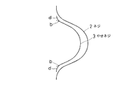
図1に示すように、ガラスびん1の口部のネジ2は、成形型の合目eの付近において、その他の部分よりも小さく形成されている。この小さく形成されている部分を「やせネジ」という。成形型は概略半円形の2つの割型を合わせることによって形成されるが、その割型の合わせ目が「合目」である。合目においては、ガラスがわずかの隙間からはみ出して、小さな突条が形成されるので、その部分のネジを若干小さく形成し、キャップのネジが損傷するのを防いでいる。
As shown in FIG. 1, the
図2は、一般部分のネジ2とやせネジ3の大きさ及び形状を比較したものである。成形型のネジ部分は、当該部分をドリルで切削して形成する。やせネジ部分は、型に対してドリルの刃を浅く入れて形成する。したがって、やせネジの基本形状は、一般部分のネジを所定量引き込んだ形状bと等しくなっている。しかし、そのままだとやせネジの裾部分が尖った形になり、その部分に欠点が生じやすくなるので、裾部分が曲線dとなるように型を2次加工している。
FIG. 2 is a comparison of the size and shape of the
成形型は、ガラスびん成形後に両側に開いて製品を脱型する。図1において、ガラスびんの口部を成形する口型は、合目から矢印方向に左右に開く。その際、ネジ2が水平であれば問題ないのであるが、ネジは傾斜しているものであるため、ネジと型とが干渉して、いわゆる「無理抜き」の状態となる。図3は、合目部分をやせネジとせず、一般部分と同じネジにした場合の、型開きの様子を表している。型開きすると、ネジ部分のガラスは型に対して、相対的に、矢印B方向に傾斜して離れていくことになる。そしてネジ部分のガラスと型が干渉する干渉部Aが生じる。干渉部における干渉量が大きいと、その部分に「びり」と呼ばれる傷が生じ、ガラスの強度が著しく低下する。
The mold is opened on both sides after the glass bottle is molded to remove the product. In FIG. 1, the mouth mold for forming the mouth portion of the glass bottle opens left and right in the direction of the arrow from the joint. At that time, if the
従来、合目部分をやせネジとすることは、型開きにおける干渉量を少なくする効果もあると信じられていた。しかし、発明者らは、図2に示す一般部分のネジ2と従来のやせネジ3について、型開きの際の干渉量を計算した。図3は一般部分のネジ、図4はやせネジの場合である。驚いたことに、一般部分のネジとやせネジでは干渉量が0.075mmで等しい値であった。すなわち、従来のやせネジは干渉量を小さくする効果は全くなかったのである。
Conventionally, it has been believed that using a thin screw at the joint portion has an effect of reducing the amount of interference in mold opening. However, the inventors calculated the amount of interference at the time of mold opening for the
従来、ガラスびんのネジの合目には、ある程度の確率で「びり」が発生し、それは避けられないものと思われていた。本発明は、型開きの際に、ネジ部分のガラスと型との干渉量を小さくすることで、「びり」の発生する確率を低くすることを課題としてなされたものである。 Conventionally, it has been thought that a “chatter” occurs at a certain probability at the joint of the screw of the glass bottle, which is unavoidable. An object of the present invention is to reduce the probability of occurrence of “chatter” by reducing the amount of interference between the screw portion glass and the mold when the mold is opened.
本発明は、ガラスびん口部の合目部分のやせネジの断面形状を、一般部分のネジの断面形状aと、該形状aを所定量引き込んだ形状bの間の両山裾に接線cを形成し、接線cと前記形状aとの接点をp、前記形状bとの接点をqとしたときに、接点q、qの間の形状が前記形状b、接点pとqの間の形状が前記接線c、接点p、pの両側の形状が前記形状aとなるように形成したことを特徴とするガラスびんである。 In the present invention, the cross-sectional shape of the thin screw at the seam portion of the glass bottle mouth portion is formed by forming a tangent line c at both mountain hems between the cross-sectional shape a of the screw of the general portion and the shape b in which the shape a is drawn by a predetermined amount When the contact point between the tangent line c and the shape a is p and the contact point with the shape b is q, the shape between the contact points q and q is the shape b, and the shape between the contact points p and q is the above-described shape. The glass bottle is characterized in that the shape on both sides of the tangential line c and the contact points p and p is the shape a.
図5は実施例のガラスびんのやせネジ3の形状を示している。同図において、aは一般部分のネジ形状(断面形状)で、ネジ高さは1.3mmである。bはネジ形状aを0.3mm水平に引き込んでネジ高さ1.0mmとした形状である。形状aとbの間の上下両山裾の間に2本の接線cを引き、各接線cと形状aとの接点をp、形状bとの接点をqとする。やせネジ3の断面形状は、2つの接点qの間を形状bとし、接点pと接点qの間を接線cとし、2つの接点pの両側を形状aとし、これらの形状を合成した形状(実線で示す形状)となっている。
FIG. 5 shows the shape of the
図6は、上記実施例のやせネジの型開きの様子を表している。この場合、ネジ部分のガラスと型の干渉量は0.035mmとなり、干渉量は従来の半分以下となっている。したがって、ネジの合目部分のびりの発生を著しく低減することができる。 FIG. 6 shows how the thin screw of the above embodiment is opened. In this case, the amount of interference between the screw portion glass and the mold is 0.035 mm, and the amount of interference is less than half of the conventional amount. Therefore, the occurrence of chatter at the joint portion of the screw can be remarkably reduced.
1 ガラスびん
2 ネジ
3 やせネジ
1
Claims (1)
一般部分のネジの断面形状(a)と、該形状(a)を所定量引き込んだ形状(b)の間の両山裾に接線(c)を形成し、接線(c)と前記形状(a)との接点を(p)、前記形状(b)との接点を(q)としたときに、接点(q)、(q)の間の形状が前記形状(b)、接点(p)と(q)の間の形状が前記接線(c)、接点(p)、(p)の両側の形状が前記形状(a)となるように形成したことを特徴とするガラスびん。 The cross-sectional shape of the thin screw at the joint of the glass bottle mouth
A tangent (c) is formed at both mountain hems between the cross-sectional shape (a) of the screw of the general portion and the shape (b) in which the shape (a) is pulled in a predetermined amount, and the tangent (c) and the shape (a) (P), and the contact point with the shape (b) is (q), the shape between the contact points (q) and (q) is the shape (b), the contact points (p) and ( The glass bottle is formed so that the shape between q) is the tangent (c), and the shapes on both sides of the contacts (p) and (p) are the shape (a).
Priority Applications (1)
| Application Number | Priority Date | Filing Date | Title |
|---|---|---|---|
| JP2005202468A JP4180586B2 (en) | 2005-07-12 | 2005-07-12 | Glass bottle |
Applications Claiming Priority (1)
| Application Number | Priority Date | Filing Date | Title |
|---|---|---|---|
| JP2005202468A JP4180586B2 (en) | 2005-07-12 | 2005-07-12 | Glass bottle |
Publications (2)
| Publication Number | Publication Date |
|---|---|
| JP2007022538A true JP2007022538A (en) | 2007-02-01 |
| JP4180586B2 JP4180586B2 (en) | 2008-11-12 |
Family
ID=37783825
Family Applications (1)
| Application Number | Title | Priority Date | Filing Date |
|---|---|---|---|
| JP2005202468A Expired - Lifetime JP4180586B2 (en) | 2005-07-12 | 2005-07-12 | Glass bottle |
Country Status (1)
| Country | Link |
|---|---|
| JP (1) | JP4180586B2 (en) |
Cited By (6)
| Publication number | Priority date | Publication date | Assignee | Title |
|---|---|---|---|---|
| JP2007076336A (en) * | 2005-09-16 | 2007-03-29 | Toyo Seikan Kaisha Ltd | Mouth and neck structure of resin molded products |
| JP2010260765A (en) * | 2009-05-07 | 2010-11-18 | Kirin Brewery Co Ltd | Glass bottle with contour pattern and method for producing the same |
| JP2010260764A (en) * | 2009-05-07 | 2010-11-18 | Kirin Brewery Co Ltd | Uneven pattern glass bottle and method for producing the same |
| CN104071407A (en) * | 2014-06-26 | 2014-10-01 | 德清才府玻璃股份有限公司 | Thread mouth glass bottle |
| CN104096925A (en) * | 2014-06-26 | 2014-10-15 | 德清才府玻璃股份有限公司 | Threaded opening glass bottle machining method capable of preventing bottle cap from being scraped |
| JP2022085524A (en) * | 2020-11-27 | 2022-06-08 | 凸版印刷株式会社 | container |
-
2005
- 2005-07-12 JP JP2005202468A patent/JP4180586B2/en not_active Expired - Lifetime
Cited By (7)
| Publication number | Priority date | Publication date | Assignee | Title |
|---|---|---|---|---|
| JP2007076336A (en) * | 2005-09-16 | 2007-03-29 | Toyo Seikan Kaisha Ltd | Mouth and neck structure of resin molded products |
| JP2010260765A (en) * | 2009-05-07 | 2010-11-18 | Kirin Brewery Co Ltd | Glass bottle with contour pattern and method for producing the same |
| JP2010260764A (en) * | 2009-05-07 | 2010-11-18 | Kirin Brewery Co Ltd | Uneven pattern glass bottle and method for producing the same |
| CN104071407A (en) * | 2014-06-26 | 2014-10-01 | 德清才府玻璃股份有限公司 | Thread mouth glass bottle |
| CN104096925A (en) * | 2014-06-26 | 2014-10-15 | 德清才府玻璃股份有限公司 | Threaded opening glass bottle machining method capable of preventing bottle cap from being scraped |
| JP2022085524A (en) * | 2020-11-27 | 2022-06-08 | 凸版印刷株式会社 | container |
| JP2025032359A (en) * | 2020-11-27 | 2025-03-11 | Toppanホールディングス株式会社 | container |
Also Published As
| Publication number | Publication date |
|---|---|
| JP4180586B2 (en) | 2008-11-12 |
Similar Documents
| Publication | Publication Date | Title |
|---|---|---|
| JP4180586B2 (en) | Glass bottle | |
| US10675675B2 (en) | Water-cooled mold for low-pressure casting of aluminum alloy wheel | |
| JP4180599B2 (en) | Glass bottle | |
| JP2009202923A (en) | Glass bottle | |
| CN205829722U (en) | A kind of terminal | |
| CN105852153B (en) | Shell opening machine adaptively opens shell track | |
| CN105834271A (en) | Deep drawing process for keeping inner circular bead unchanged and shrinking outer circular bead of cup bottom | |
| CN114211208B (en) | Method for processing arc surface of permanent ferrite magnetic shoe alloy die | |
| CN207479529U (en) | A kind of hub of motorcycle mold equipped with insert | |
| JP7366774B2 (en) | Rough mold and method for manufacturing glass containers using the rough mold | |
| JP5889011B2 (en) | Mold cap for screw cap with seal | |
| CN103185061B (en) | Shaft-hole matching mechanism and its rotating shaft | |
| CN208788674U (en) | Silent roll-in cutting off bumper structure | |
| CN110303109A (en) | A kind of high temperature alloy disk forging embryo material | |
| CN206373344U (en) | A kind of aluminum alloy die-casting die | |
| CN210560061U (en) | Screw type pressure blowing glass forming die | |
| CN106825356B (en) | A kind of method of precision forged blade molded line finishing | |
| CN211101439U (en) | Blank pressing riser with step | |
| CN112570659B (en) | Parting method for overturning guide rail | |
| CN104163559B (en) | Improved glass bottle bottle neck mould | |
| CN201736904U (en) | Opening stop structure of glove box | |
| CN206863370U (en) | Unilateral flush picture frame metal wire rod | |
| CN206416439U (en) | A square hole splicing mold for socket parts | |
| CN205661527U (en) | Car parcel shelf backplate | |
| CN106623852A (en) | Aluminum alloy pressure casting die |
Legal Events
| Date | Code | Title | Description |
|---|---|---|---|
| A977 | Report on retrieval |
Free format text: JAPANESE INTERMEDIATE CODE: A971007 Effective date: 20080722 |
|
| TRDD | Decision of grant or rejection written | ||
| A01 | Written decision to grant a patent or to grant a registration (utility model) |
Free format text: JAPANESE INTERMEDIATE CODE: A01 Effective date: 20080826 |
|
| A01 | Written decision to grant a patent or to grant a registration (utility model) |
Free format text: JAPANESE INTERMEDIATE CODE: A01 |
|
| A61 | First payment of annual fees (during grant procedure) |
Free format text: JAPANESE INTERMEDIATE CODE: A61 Effective date: 20080827 |
|
| R150 | Certificate of patent or registration of utility model |
Ref document number: 4180586 Country of ref document: JP Free format text: JAPANESE INTERMEDIATE CODE: R150 Free format text: JAPANESE INTERMEDIATE CODE: R150 |
|
| FPAY | Renewal fee payment (event date is renewal date of database) |
Free format text: PAYMENT UNTIL: 20110905 Year of fee payment: 3 |
|
| FPAY | Renewal fee payment (event date is renewal date of database) |
Free format text: PAYMENT UNTIL: 20120905 Year of fee payment: 4 |
|
| FPAY | Renewal fee payment (event date is renewal date of database) |
Free format text: PAYMENT UNTIL: 20120905 Year of fee payment: 4 |
|
| FPAY | Renewal fee payment (event date is renewal date of database) |
Free format text: PAYMENT UNTIL: 20130905 Year of fee payment: 5 |
|
| FPAY | Renewal fee payment (event date is renewal date of database) |
Free format text: PAYMENT UNTIL: 20130905 Year of fee payment: 5 |
|
| S531 | Written request for registration of change of domicile |
Free format text: JAPANESE INTERMEDIATE CODE: R313531 |
|
| FPAY | Renewal fee payment (event date is renewal date of database) |
Free format text: PAYMENT UNTIL: 20130905 Year of fee payment: 5 |
|
| R350 | Written notification of registration of transfer |
Free format text: JAPANESE INTERMEDIATE CODE: R350 |
|
| EXPY | Cancellation because of completion of term |