JP2007021807A - Method and device for processing image, and image recorder - Google Patents
Method and device for processing image, and image recorder Download PDFInfo
- Publication number
- JP2007021807A JP2007021807A JP2005204467A JP2005204467A JP2007021807A JP 2007021807 A JP2007021807 A JP 2007021807A JP 2005204467 A JP2005204467 A JP 2005204467A JP 2005204467 A JP2005204467 A JP 2005204467A JP 2007021807 A JP2007021807 A JP 2007021807A
- Authority
- JP
- Japan
- Prior art keywords
- landing position
- distance
- droplet
- recording
- position deviation
- Prior art date
- Legal status (The legal status is an assumption and is not a legal conclusion. Google has not performed a legal analysis and makes no representation as to the accuracy of the status listed.)
- Pending
Links
Images


Classifications
-
- B—PERFORMING OPERATIONS; TRANSPORTING
- B41—PRINTING; LINING MACHINES; TYPEWRITERS; STAMPS
- B41J—TYPEWRITERS; SELECTIVE PRINTING MECHANISMS, i.e. MECHANISMS PRINTING OTHERWISE THAN FROM A FORME; CORRECTION OF TYPOGRAPHICAL ERRORS
- B41J2/00—Typewriters or selective printing mechanisms characterised by the printing or marking process for which they are designed
- B41J2/005—Typewriters or selective printing mechanisms characterised by the printing or marking process for which they are designed characterised by bringing liquid or particles selectively into contact with a printing material
- B41J2/01—Ink jet
- B41J2/21—Ink jet for multi-colour printing
- B41J2/2132—Print quality control characterised by dot disposition, e.g. for reducing white stripes or banding
- B41J2/2135—Alignment of dots
-
- B—PERFORMING OPERATIONS; TRANSPORTING
- B41—PRINTING; LINING MACHINES; TYPEWRITERS; STAMPS
- B41J—TYPEWRITERS; SELECTIVE PRINTING MECHANISMS, i.e. MECHANISMS PRINTING OTHERWISE THAN FROM A FORME; CORRECTION OF TYPOGRAPHICAL ERRORS
- B41J2/00—Typewriters or selective printing mechanisms characterised by the printing or marking process for which they are designed
- B41J2/005—Typewriters or selective printing mechanisms characterised by the printing or marking process for which they are designed characterised by bringing liquid or particles selectively into contact with a printing material
- B41J2/01—Ink jet
- B41J2/21—Ink jet for multi-colour printing
- B41J2/2132—Print quality control characterised by dot disposition, e.g. for reducing white stripes or banding
- B41J2/2146—Print quality control characterised by dot disposition, e.g. for reducing white stripes or banding for line print heads
Landscapes
- Engineering & Computer Science (AREA)
- Quality & Reliability (AREA)
- Ink Jet (AREA)
- Particle Formation And Scattering Control In Inkjet Printers (AREA)
Abstract
Description
本発明は画像処理方法及び装置並びに画像記録装置に係り、特に複数の液滴吐出口(ノズル)を有する記録ヘッドを用いるインクジェット記録装置における打滴の着弾位置ばらつきによるスジムラの発生を抑制するのに好適な画像処理技術、並びにこれを用いた画像記録装置に関する。 The present invention relates to an image processing method and apparatus, and an image recording apparatus, and more particularly to suppressing the occurrence of unevenness due to variations in the landing positions of droplets in an ink jet recording apparatus using a recording head having a plurality of droplet discharge ports (nozzles). The present invention relates to a suitable image processing technique and an image recording apparatus using the same.
インクジェット記録装置では、ノズルから吐出されるインクの着弾位置が所望の位置からずれることにより、記録画像にスジムラ(スジ状の濃度ムラ)が発生し、画質の劣化が生じる。とりわけ、1回の走査で画像記録を行うラインヘッド方式(Full Width Array)の記録では、ノズル固有の着弾位置ずれによるスジムラは顕著となり大きな問題となる。 In the ink jet recording apparatus, the landing position of the ink ejected from the nozzles is deviated from a desired position, thereby causing unevenness in the recorded image (streaky density unevenness) and degradation of image quality. In particular, in a line head type (Full Width Array) recording in which an image is recorded by one scan, the unevenness due to the deviation of the landing position unique to the nozzle becomes significant and becomes a serious problem.
この着弾位置ずれの主たる要因は、ノズル近傍の撥水膜の劣化や傷、ノズル近傍へのインクミストやゴミの付着による打滴の斜め方向飛翔である。したがって、ノズルと媒体面(記録面)の距離が変化すると、打滴の着弾位置が変化し、スジムラの程度が変わってしまう。図18の表は、ノズル−媒体間距離と着弾位置ずれ量の関係を例示したものであり、斜め飛翔角度が1度の場合(正常な飛翔方向に対して1度ずれた場合)と、2度の場合の例が示されている。図示のように、着弾位置ずれ量は、ノズル−媒体間距離と斜め飛翔角度とに応じて変化する。なお、ノズル−媒体間距離は、媒体の厚みなどによって変化する。 The main causes of this landing position deviation are the deterioration and scratches of the water-repellent film near the nozzle, and the slanting flight of the droplets due to ink mist and dust adhering to the vicinity of the nozzle. Therefore, when the distance between the nozzle and the medium surface (recording surface) changes, the landing position of the droplets changes and the degree of unevenness changes. The table in FIG. 18 exemplifies the relationship between the nozzle-medium distance and the landing position deviation amount. When the oblique flight angle is 1 degree (when it is deviated 1 degree from the normal flight direction), 2 An example of degrees is shown. As shown in the drawing, the amount of landing position deviation changes according to the nozzle-medium distance and the oblique flight angle. The nozzle-medium distance varies depending on the thickness of the medium.
特許文献1は、記録材の厚み(すなわち、ノズル−媒体間の距離)により、着弾位置のばらつきが縮小されたり、拡大されたりして画質のばらつきが発生することを課題とし、その解決手段として、媒体の厚みに応じてノズル面と媒体間の距離を一定に保つよう距離の制御手段を設けている。 Japanese Patent Laid-Open No. 2004-260688 has a problem that variations in landing positions are reduced or expanded depending on the thickness of the recording material (that is, the distance between the nozzle and the medium), resulting in variations in image quality. The distance control means is provided so as to keep the distance between the nozzle surface and the medium constant according to the thickness of the medium.
特許文献2は、スジムラの視認性を低下させる手段として、打滴の飛翔方向を制御する飛翔偏向手段を具備し、ノズル面と媒体間の距離に応じて偏向量を可変する構成を開示している。
しかしながら、特許文献1で提案されている構成は、メカ的な距離の制御機構を必要とし、高コストである。また、特許文献2で提案されている構成は、飛翔偏向手段として、1ノズルに2つの駆動素子(サーマル素子)を設ける必要があるために、その分コストがかかる。
However, the configuration proposed in
更にまた、スジムラの補正を行うためには、着弾位置ずれ状態を測定することが必要であるが、図18の表からも明らかなように、そのずれ量は、およそ数μm〜20μmの範囲で変化する。したがって、このμmオーダーのずれ量を精度よく測定することも要求される。 Furthermore, in order to correct the unevenness, it is necessary to measure the landing position deviation state. As is apparent from the table of FIG. 18, the deviation amount is in the range of about several μm to 20 μm. Change. Therefore, it is also required to accurately measure the deviation amount on the order of μm.
本発明はこのような事情に鑑みてなされたもので、ノズル面と記録面の間の距離に応じて変化する打滴の斜め飛翔による着弾位置ずれを精度よく補正することができる画像処理方法及び装置、並びにこれを用いた画像記録装置を提供することを目的とする。 The present invention has been made in view of such circumstances, and an image processing method capable of accurately correcting a landing position deviation due to oblique flight of droplet ejection that changes according to a distance between a nozzle surface and a recording surface, and It is an object to provide an apparatus and an image recording apparatus using the apparatus.
前記目的を達成するために、請求項1に係る画像処理方法は、複数の液滴吐出口が形成された液体吐出ヘッドの吐出面と、前記液滴吐出口から吐出される液体が着弾する記録面との間の距離を把握し、前記距離に基づいて前記記録面上での前記液滴吐出口から吐出される液滴の着弾位置ずれ量を特定し、前記特定した着弾位置ずれ量に応じて画像データを補正して中間階調処理を行うことにより打滴配置データを生成することを特徴とする。
In order to achieve the above object, an image processing method according to
本発明によれば、液体吐出ヘッドの吐出面と記録面との間の距離に応じて変化する着弾位置ずれ(例えば、打滴の斜め飛翔による着弾位置ずれ)を、その距離との相関に基づいて特定し、特定した着弾位置ずれ量に基づいて、当該着弾位置ずれに起因するスジムラの発生を抑える観点から画像データの補正を行い、中間階調処理(ハーフトーニング処理)を経て打滴配置(ドット配置)データを得る。これにより、吐出面と記録面との間の距離の変化に伴う着弾位置ずれに対して適応的に対応した高精度の補正が可能であり、着弾位置ずれに起因するスジムラの視認性を低減し得る打滴配置を実現することができる。 According to the present invention, the landing position deviation (for example, landing position deviation due to slanted droplet ejection) that changes according to the distance between the ejection surface of the liquid ejection head and the recording surface is based on the correlation with the distance. Based on the specified landing position deviation amount, the image data is corrected from the viewpoint of suppressing the occurrence of unevenness due to the landing position deviation, and the droplet placement arrangement (through halftoning process) is performed. Dot arrangement) data. This makes it possible to perform high-accuracy correction that adaptively responds to landing position deviations due to changes in the distance between the ejection surface and the recording surface, and reduces the visibility of uneven stripes due to landing position deviations. The resulting droplet placement arrangement can be realized.
本発明は、打滴配置を決定する際の画像信号処理の段階で着弾位置ずれを考慮した補正が行われるため、特許文献1,2に開示の技術と比較して、メカ的な制御機構や飛翔偏向用の駆動素子の追加などが不要であり、比較的低コストで補正効果を得ることができる。
Since the present invention performs correction in consideration of the landing position deviation at the stage of image signal processing when determining the droplet placement, compared to the techniques disclosed in
請求項2に係る画像処理方法は、複数の液滴吐出口が形成された液体吐出ヘッドの吐出面から第1の距離にある第1の記録面上で測定される前記液滴吐出口から吐出される液滴の着弾位置ずれ量の情報を取得する第1の着弾位置誤差情報取得工程と、前記吐出面から前記第1の距離とは異なる第2の距離にある第2の記録面について、前記第2の距離の情報を取得する第2の距離情報取得工程と、前記第1及び第2の距離と前記第1の記録面上で測定された前記着弾位置ずれ量に基づいて、前記第2の記録面上における着弾位置ずれ量を求める第2の着弾位置誤差演算工程と、前記第2の着弾位置ずれ量演算工程で求めた前記第2の記録面上における着弾位置ずれ量に応じて画像データを補正して中間階調処理を行うことにより打滴配置データを生成する打滴配置決定工程と、を含むことを特徴とする。
The image processing method according to
本発明によれば、吐出面から第1の距離を隔てた第1の記録面における着弾位置ずれ量の情報を基にして、吐出面から第2の距離にある第2の記録面における着弾位置ずれ量を推定(計算により算出)することができる。この第2の着弾位置誤差演算工程では、吐出面−記録面間の距離と着弾位置ずれ量の相関を示す関数を用いてもよいし、ルックアップテーブルなどを用いてもよい。このため、第2の記録面については着弾位置ずれ量の測定(実測)が不要となる。すなわち、本発明によれば、吐出面からの距離が異なる複数種の記録面について、記録面ごとに着弾位置ずれ量を毎回測定する必要がなく、基準となる第1の距離にある第1の記録面における着弾位置ずれ量を測定した後は、対象とする記録面と吐出面の距離を特定するだけで、当該記録面における着弾位置ずれを求めることができ、多様な記録面に対して容易に高精度の補正を実現できる。また、測定用のテストプリントを省略でき、無駄な記録媒体の消費を抑制できる。なお、第2の記録面における着弾位置ずれ量の推定(第2の着弾位置誤差演算工程)に際しては、吐出面−記録面間の距離と着弾位置ずれ量との相関を示す関数(或いは演算式)を用いてもよいし、ルックアップテーブルなどを用いてもよい。 According to the present invention, the landing position on the second recording surface at the second distance from the ejection surface based on the information on the amount of landing position deviation on the first recording surface that is separated from the ejection surface by the first distance. The amount of deviation can be estimated (calculated by calculation). In the second landing position error calculation step, a function indicating a correlation between the distance between the ejection surface and the recording surface and the landing position deviation amount may be used, or a lookup table may be used. For this reason, it is not necessary to measure (actually measure) the amount of landing position deviation for the second recording surface. That is, according to the present invention, it is not necessary to measure the amount of landing position deviation for each recording surface for a plurality of types of recording surfaces having different distances from the ejection surface, and the first distance at the first reference distance is used. After measuring the amount of landing position deviation on the recording surface, it is possible to determine the landing position deviation on the recording surface simply by specifying the distance between the target recording surface and the ejection surface. Highly accurate correction can be realized. Further, the test print for measurement can be omitted, and the consumption of useless recording media can be suppressed. In estimating the landing position deviation amount on the second recording surface (second landing position error calculation step), a function (or a calculation formula) indicating the correlation between the distance between the ejection surface and the recording surface and the landing position deviation amount. ) Or a lookup table or the like.
請求項3に係る発明は、請求項2記載の画像処理方法の一態様であり、前記第1の距離は、前記第2の距離よりも長いことを特徴とする。 A third aspect of the present invention is an aspect of the image processing method according to the second aspect, wherein the first distance is longer than the second distance.
打滴の斜め飛翔による着弾位置のずれ量(記録面上での理想の着弾位置からの誤差)は、吐出面と記録面間の距離(飛翔距離)が長いほど大きくなるので、飛翔距離の長い第1の距離における第1の記録面上での着弾位置ずれ量を測定することにより、ずれ量の測定が容易となり、ずれ量測定手段に要求される精度を下げることができる。 The amount of deviation in the landing position due to slanted droplet ejection (error from the ideal landing position on the recording surface) increases as the distance between the ejection surface and the recording surface (flying distance) increases. By measuring the landing position deviation amount on the first recording surface at the first distance, the deviation amount can be easily measured, and the accuracy required for the deviation amount measuring means can be lowered.
請求項4に係る発明は、前記目的を達成する画像処理装置を提供する。すなわち、請求項4に係る画像処理装置は、複数の液滴吐出口が形成された液体吐出ヘッドの吐出面と、前記液滴吐出口から吐出される液体が着弾する記録面との距離を特定する距離特定手段と、前記距離に基づいて前記記録面上での前記液滴吐出口から吐出される液滴の着弾位置ずれ量を求める着弾位置誤差演算手段と、前記着弾位置誤差演算手段によって求めた着弾位置ずれ量に応じて画像データを補正して中間階調処理を行うことにより打滴配置データを生成する打滴配置決定手段と、を備えたことを特徴とする。 The invention according to claim 4 provides an image processing apparatus that achieves the object. That is, the image processing apparatus according to claim 4 specifies a distance between a discharge surface of a liquid discharge head formed with a plurality of droplet discharge ports and a recording surface on which liquid discharged from the droplet discharge ports lands. A distance specifying means for determining the amount of landing position deviation of a droplet discharged from the droplet discharge port on the recording surface based on the distance, and a landing position error calculating means for calculating a landing position error calculating means for calculating the landing position error calculating means. And a droplet placement determination means for generating droplet placement data by correcting the image data in accordance with the amount of landing position deviation and performing intermediate gradation processing.
吐出面と記録面間の距離を特定する手段(距離特定手段)としては、実際にその距離を測定する測定手段を用いてもよいし、使用される記録媒体の厚みの情報を獲得する手段を用いてもよい。なお、記録媒体の厚みの情報を獲得する手段としては、実際に厚みを測定する手段の他、ユーザインターフェースを利用して厚み情報を入力する態様、記録媒体を収容している容器(マガジン、カセットなど)に付した情報記録部から読み取る態様などがあり得る。 As a means for specifying the distance between the ejection surface and the recording surface (distance specifying means), a measuring means for actually measuring the distance may be used, or a means for acquiring information on the thickness of the recording medium used. It may be used. As a means for acquiring information on the thickness of the recording medium, in addition to means for actually measuring the thickness, a mode in which the thickness information is input using a user interface, a container (magazine, cassette) containing the recording medium is used. And the like may be read from the information recording unit attached to the above.
請求項5に係る画像処理装置は、複数の液滴吐出口が形成された液体吐出ヘッドの吐出面から第1の距離にある第1の記録面上で測定される前記液滴吐出口から吐出される液滴の着弾位置ずれ量の情報を取得する第1の着弾位置誤差情報取得手段と、前記吐出面から前記第1の距離とは異なる第2の距離にある第2の記録面について、前記第2の距離の情報を取得する第2の距離情報取得手段と、前記第1及び第2の距離と前記第1の記録面上で測定された前記着弾位置ずれ量に基づいて、前記第2の記録面上における着弾位置ずれ量を求める第2の着弾位置誤差演算手段と、前記第2の着弾位置誤差演算手段で求めた前記第2の記録面上における着弾位置ずれ量に応じて画像データを補正して中間階調処理を行うことにより打滴配置データを生成する打滴配置決定手段と、を備えたことを特徴とする。 According to a fifth aspect of the present invention, there is provided an image processing apparatus for ejecting from the droplet ejection port measured on the first recording surface at a first distance from the ejection surface of the liquid ejection head in which a plurality of droplet ejection ports are formed. First landing position error information acquisition means for acquiring information on the amount of landing position deviation of the liquid droplets, and a second recording surface at a second distance different from the first distance from the ejection surface, Based on second distance information acquisition means for acquiring information on the second distance, the first and second distances, and the amount of landing position deviation measured on the first recording surface, Second landing position error calculation means for obtaining a landing position deviation amount on the second recording surface, and an image corresponding to the landing position deviation amount on the second recording surface obtained by the second landing position error calculation means. Droplet placement data by correcting the data and performing halftone processing A droplet deposition arrangement determining means for generating, and further comprising a.
第1の距離にある第1の記録面上における着弾位置ずれ量の情報を取得する手段(第1の着弾位置誤差情報取得手段)は、予め測定しておいた着弾位置ずれ量に関する情報をメモリ等の記憶手段に格納しておき、必要な情報を読み出すことによって情報を取得してもよいし、実際にテストパターン等を印字してその印字結果を読み取り、解析処理を行って着弾位置ずれ量の情報を取得してもよい。着弾位置のずれ量が状況によって変化することに鑑み、適宜のタイミングで情報を更新する態様が好ましい。 Means (first landing position error information acquisition means) for acquiring information on the landing position deviation amount on the first recording surface at the first distance stores information on the landing position deviation amount measured in advance. The information may be obtained by reading the necessary information in advance by storing it in a storage means such as a test pattern. May be obtained. In view of the fact that the displacement amount of the landing position varies depending on the situation, an aspect in which information is updated at an appropriate timing is preferable.
第2の距離の情報を取得する手段(第2の距離情報取得手段)としては、実際にその距離を測定する測定手段を用いてもよいし、使用される記録媒体の厚みの情報を獲得する手段を用いてもよい。なお、記録媒体の厚みの情報を獲得する手段としては、実際に厚みを測定する手段の他、ユーザインターフェースを利用して厚み情報を入力する態様、記録媒体を収容している容器(マガジン、カセットなど)に付した情報記録部から読み取る態様などがあり得る。 As the means for acquiring the second distance information (second distance information acquiring means), a measuring means for actually measuring the distance may be used, or information on the thickness of the recording medium to be used is acquired. Means may be used. As a means for acquiring information on the thickness of the recording medium, in addition to means for actually measuring the thickness, a mode in which the thickness information is input using a user interface, a container (magazine, cassette) containing the recording medium is used. And the like may be read from the information recording unit attached to the above.
請求項6に係る発明は、請求項4又は5記載の画像処理装置の一態様であり、前記打滴配置決定手段は、前記複数の液滴吐出口のうち、出力濃度の補正に用いるN個(ただし、Nは2以上の整数)の液滴吐出口を設定する補正範囲設定手段と、前記液滴吐出口から吐出される液滴の着弾位置誤差に起因する濃度ムラの空間周波数特性を表すパワースペクトルの周波数原点(f=0)における微分係数が略0となる条件を含む補正条件に基づいて前記N個の液滴吐出口から吐出される液滴の濃度補正係数を決定する補正係数決定手段と、前記補正係数決定手段で決定された濃度補正係数を用いて出力濃度を補正する演算を行う補正処理手段と、を含むことを特徴とする。 A sixth aspect of the present invention is an aspect of the image processing apparatus according to the fourth or fifth aspect, wherein the droplet ejection arrangement determining unit includes N of the plurality of droplet discharge ports used for correcting the output density. (Where N is an integer of 2 or more) correction range setting means for setting droplet discharge ports, and spatial frequency characteristics of density unevenness caused by landing position errors of droplets discharged from the droplet discharge ports Determination of correction coefficient for determining density correction coefficient of droplets discharged from the N droplet discharge ports based on correction conditions including a condition that the differential coefficient at the frequency origin (f = 0) of the power spectrum is substantially zero. And correction processing means for performing a calculation for correcting the output density using the density correction coefficient determined by the correction coefficient determination means.
記録画像における濃度の不均一性(濃度ムラ)は、空間周波数特性(パワースペクトル)での強度で表すことができるが、人間の視覚では高周波成分を視認できないため、濃度ムラの視認性はパワースペクトルの低周波成分で評価できる。濃度補正係数を用いた補正後のパワースペクトルの周波数原点(f=0)における微分係数が略0となる条件を用いて濃度補正係数を決めるようにしたことで、周波数原点でのパワースペクトルの強度が最小となり、原点付近(すなわち、低周波領域)のパワースペクトルを小さく抑えることができる。これにより、精度のよいムラ補正を実現できる。 The density non-uniformity (density unevenness) in the recorded image can be expressed by the intensity in the spatial frequency characteristic (power spectrum), but since the high frequency component cannot be visually recognized by human vision, the density unevenness visibility is the power spectrum. It can be evaluated with the low frequency component. Since the density correction coefficient is determined using the condition that the differential coefficient at the frequency origin (f = 0) of the power spectrum after correction using the density correction coefficient is approximately 0, the intensity of the power spectrum at the frequency origin Is minimized, and the power spectrum near the origin (that is, in the low frequency region) can be kept small. Thereby, accurate unevenness correction can be realized.
また、請求項6に係る発明の一態様によれば、前記補正条件は、空間周波数の直流成分の保存条件と、N−1次までの微分係数が略0となる条件より得られるN本の連立方程式で表されることを特徴とする。 According to an aspect of the invention relating to claim 6, the correction condition is obtained by N storage conditions obtained from a storage condition of a direct current component of spatial frequency and a condition in which a differential coefficient up to the N−1 order is substantially zero. It is expressed by simultaneous equations.
N個の補正ノズルについてそれぞれ濃度補正係数を求める場合、未知数はN個あるため、直流(DC)成分の保存条件と、N−1次までの微分係数が略0となる条件を用いることで、N本の方程式を得て、これを解くことにより、全ての未知数を決定することができる。 When obtaining density correction coefficients for each of N correction nozzles, since there are N unknowns, by using a condition for storing a direct current (DC) component and a condition in which differential coefficients up to the (N−1) th order are substantially zero, All unknowns can be determined by obtaining N equations and solving them.
また、より高次の微分係数が略0となる条件を満たすことにより、周波数原点からの周波数の増加に対してパワースペクトルの増加の程度が一層低く抑えられ、低周波成分の強度がより小さい値に保たれる。 Further, by satisfying the condition that the higher-order differential coefficient is substantially 0, the degree of increase in the power spectrum is further suppressed with respect to the increase in frequency from the frequency origin, and the intensity of the low frequency component is smaller. To be kept.
濃度補正係数diについては、例えば、ノズル(液滴吐出口)の位置を特定するインデックスをiとし、ノズルiの記録位置をxiとするとき、ノズルiの濃度補正係数diは、次式 Regarding the density correction coefficient di, for example, when the index for specifying the position of the nozzle (droplet ejection port) is i and the recording position of the nozzle i is x i, the density correction coefficient di for the nozzle i is given by

を用いて決定される。 Is determined.
濃度プロファイルの重心位置に注目して、プロファイルをδ関数で近似するδ関数型印字モデルを用いた数学的取り扱いによって濃度補正係数の計算式を得ることができる。なお、実際の装置への適用については、上記計算式〔数1〕で求めた厳密解をそのまま利用する態様に限定されず、厳密解に対して適宜の補正を行って実用的な値への修正を行ってもよい。 Focusing on the position of the center of gravity of the density profile, a formula for calculating the density correction coefficient can be obtained by mathematical handling using a δ function type printing model that approximates the profile with a δ function. Note that application to an actual apparatus is not limited to an embodiment in which the exact solution obtained by the above calculation formula [Equation 1] is used as it is, and an appropriate correction is performed on the exact solution to obtain a practical value. Corrections may be made.
また、前記複数のノズルのうち、インデックスkで表されるノズルの持つ着弾位置誤差に対して、当該ノズルkを含む周囲N個の補正ノズルの範囲でそれぞれ濃度補正係数が求められ、ノズルkの持つ着弾位置誤差に対するノズルiの濃度補正係数をd(i,k)とするとき、ノズルiのトータルの濃度補正係数diは、kを変えて求めたd(i,k)の線形結合として求められることを特徴とする。 In addition, with respect to the landing position error of the nozzle represented by the index k among the plurality of nozzles, density correction coefficients are respectively obtained in a range of N correction nozzles including the nozzle k. When the density correction coefficient of the nozzle i for the landing position error is d (i, k), the total density correction coefficient di of the nozzle i is obtained as a linear combination of d (i, k) obtained by changing k. It is characterized by being able to.
あるノズルiに対して複数のノズルの着弾位置誤差に対する濃度補正係数がそれぞれ独立的に求められ、当該ノズルiのトータルの濃度補正係数は、独立に算出された濃度補正係数の重ね合わせ(線形結合)として求められる。 Density correction coefficients for the landing position errors of a plurality of nozzles are independently obtained for a certain nozzle i, and the total density correction coefficient for the nozzle i is superimposed on the density correction coefficients calculated independently (linear combination) ).
このとき、全ての記録素子(全てのk)の着弾位置誤差を補正対象として、全てのd(i,k)の線形結合を求めてもよいし、所定の閾値を超える着弾位置誤差をもつノズルのみを補正対象とするなど、ある条件で選択された一部のインデックスkに係るd(i,k)の線形結合を求めてもよい。 At this time, the landing position error of all the printing elements (all k) may be corrected, and the linear combination of all d (i, k) may be obtained, or the nozzle having the landing position error exceeding a predetermined threshold value. Alternatively, a linear combination of d (i, k) related to a part of the indexes k selected under a certain condition may be obtained.
請求項7に係る発明は前記目的を達成する画像記録装置を提供する。すなわち、請求項7に係る画像記録装置は、複数の液滴吐出口が形成された液体吐出ヘッドと、前記液体吐出ヘッド及び被記録媒体のうち少なくとも一方を搬送して前記液体吐出ヘッドと前記被記録媒体を相対移動させる搬送手段と、前記液体吐出ヘッドの吐出面から第1の距離にある第1の記録面上で測定された前記液滴吐出口から吐出される液滴の着弾位置ずれ量と前記第1の距離の情報を記憶しておく記憶手段と、前記吐出面から前記第1の距離とは異なる第2の距離にある第2の記録面について、前記第2の距離の情報を取得する第2の距離情報取得手段と、前記記憶手段に記憶されている前記第1の距離及び前記第1の記録面上における前記着弾位置ずれ量、並びに前記第2の距離情報取得手段で取得された前記第2の距離に基づいて、前記第2の記録面上における着弾位置ずれ量を求める第2の着弾位置誤差演算手段と、前記第2の着弾位置誤差演算手段で求めた前記第2の記録面上における着弾位置ずれ量に応じて画像データを補正して中間階調処理を行うことで打滴配置データを生成する打滴配置決定手段と、前記打滴配置決定手段によって生成された打滴配置データに基づいて前記液滴吐出口からの吐出動作を制御する吐出制御手段と、を備えたことを特徴とする。 The invention according to claim 7 provides an image recording apparatus that achieves the object. That is, an image recording apparatus according to a seventh aspect transports at least one of the liquid discharge head in which a plurality of liquid droplet discharge ports are formed and the liquid discharge head and the recording medium, and the liquid discharge head and the target recording medium. Landing position deviation amount of droplets ejected from the droplet ejection port measured on a first recording surface at a first distance from the ejection surface of the liquid ejection head, and a conveying unit that relatively moves the recording medium Storage means for storing information on the first distance, and information on the second distance for a second recording surface at a second distance different from the first distance from the ejection surface. Acquired by the second distance information acquisition means to be acquired, the first distance stored in the storage means, the amount of landing position deviation on the first recording surface, and the second distance information acquisition means Based on the second distance The second landing position error calculating means for obtaining the landing position deviation amount on the second recording surface, and the landing position deviation amount obtained by the second landing position error calculating means. The droplet ejection arrangement determining means for generating droplet ejection arrangement data by correcting the image data in accordance with the image data and performing the halftone process, and the liquid ejection based on the droplet ejection arrangement data generated by the droplet ejection arrangement determining means And a discharge control means for controlling a discharge operation from the droplet discharge port.
本発明に係る画像記録装置の一態様としてのインクジェット記録装置は、ドットを形成するためのインク液滴を吐出するノズル及び吐出圧を発生させる圧力発生手段(圧電素子や加熱素子など)を含む液滴吐出素子を複数配列させた液滴吐出素子列を有する液体吐出ヘッド(「記録ヘッド」に相当)と、画像データから生成された打滴配置データに基づいて記録ヘッドからの液滴の吐出を制御する吐出制御手段とを備え、前記ノズルから吐出した液滴によって記録媒体上に画像を形成する。 An ink jet recording apparatus as an aspect of an image recording apparatus according to the present invention includes a nozzle that discharges ink droplets for forming dots and a pressure generation unit (such as a piezoelectric element or a heating element) that generates discharge pressure. A liquid ejection head (corresponding to a “recording head”) having a droplet ejection element array in which a plurality of droplet ejection elements are arranged, and ejection of droplets from the recording head based on droplet placement data generated from image data An ejection control means for controlling, and an image is formed on the recording medium by droplets ejected from the nozzle.
記録ヘッドの構成例として、記録媒体の全幅に対応する長さにわたって複数のノズルを配列させたフルライン型のヘッドを用いることができる。この場合、記録媒体の全幅に対応する長さに満たないノズル列を有する比較的短尺の記録ヘッドモジュールを複数個組み合わせ、これらを繋ぎ合わせることで全体として記録媒体の全幅に対応する長さのノズル列を構成する態様がある。 As a configuration example of the recording head, a full line type head in which a plurality of nozzles are arranged over a length corresponding to the entire width of the recording medium can be used. In this case, a combination of a plurality of relatively short recording head modules having nozzle rows that are less than the length corresponding to the entire width of the recording medium, and connecting them together, the nozzle having a length corresponding to the entire width of the recording medium as a whole. There is an aspect that constitutes a column.
フルライン型のヘッドは、通常、記録媒体の相対的な送り方向(相対的搬送方向)と直交する方向に沿って配置されるが、搬送方向と直交する方向に対して、ある所定の角度を持たせた斜め方向に沿って記録ヘッドを配置する態様もあり得る。 A full-line type head is usually arranged along a direction perpendicular to the relative feeding direction (relative conveyance direction) of the recording medium, but has a certain angle with respect to the direction perpendicular to the conveyance direction. There may be a mode in which the recording head is arranged along the oblique direction.
「記録媒体」は、液体吐出ヘッド(記録ヘッド)から吐出される液が付着する媒体であり、記録ヘッドの作用によって画像の記録を受ける。すなわち、「記録媒体」は、印字媒体、被画像形成媒体、被記録媒体、受像媒体、被吐出媒体など呼ばれ得るものであり、連続用紙、カット紙、シール用紙、OHPシート等の樹脂シート、フイルム、布、配線パターン等が形成されるプリント基板、中間転写媒体、その他材質や形状を問わず、様々な媒体を含む。 The “recording medium” is a medium to which liquid ejected from a liquid ejection head (recording head) adheres, and receives an image recording by the action of the recording head. That is, the “recording medium” can be called a printing medium, an image forming medium, a recording medium, an image receiving medium, an ejected medium, and the like, a continuous sheet, a cut sheet, a seal sheet, a resin sheet such as an OHP sheet, Various media are included regardless of the material and shape, such as a printed board on which a film, cloth, wiring pattern, or the like is formed, an intermediate transfer medium, and the like.
「搬送手段」は、停止した(固定された)記録ヘッドに対して記録媒体を搬送する態様、停止した記録媒体に対して記録ヘッドを移動させる態様、或いは、記録ヘッドと記録媒体の両方を移動させる態様のいずれをも含む。 “Conveyance means” means a mode in which the recording medium is transported to a stopped (fixed) recording head, a mode in which the recording head is moved relative to the stopped recording medium, or a movement of both the recording head and the recording medium Any of the embodiments are included.
インクジェットヘッドによって、カラー画像を形成する場合は、複数色のインク(記録液)の色別に記録ヘッドを配置してもよいし、1つの記録ヘッドから複数色のインクを吐出可能な構成としてもよい。 When a color image is formed by an inkjet head, a recording head may be arranged for each color of a plurality of colors (recording liquids), or a configuration in which a plurality of colors of ink can be discharged from one recording head may be adopted. .
また、本発明は、上記のフルライン型のヘッドに限らず、シャトルスキャン方式の記録ヘッド(記録媒体の搬送方向に略直交する方向に往復移動しながら打滴を行う記録ヘッド)についても適用可能である。 The present invention is not limited to the full-line head described above, but can also be applied to shuttle scan type recording heads (recording heads that perform droplet ejection while reciprocating in a direction substantially perpendicular to the recording medium conveyance direction). It is.
請求項8に係る発明は、請求項7記載の画像記録装置の一態様であり、前記第1の記録面上に所定のテストパターンを記録するように前記液体吐出ヘッドの吐出駆動を制御するテストパターン記録制御手段と、前記第1の記録面上に記録された前記テストパターンから着弾位置ずれ量を測定する測定手段と、を備え、前記測定手段で測定した着弾位置ずれ量の情報が前記記憶手段に記憶されることを特徴とする。 The invention according to an eighth aspect is an aspect of the image recording apparatus according to the seventh aspect, wherein the test for controlling the ejection drive of the liquid ejection head so as to record a predetermined test pattern on the first recording surface. Pattern recording control means, and measuring means for measuring the amount of landing position deviation from the test pattern recorded on the first recording surface, information on the amount of landing position deviation measured by the measuring means is stored in the memory It is stored in the means.
請求項8の態様によれば、予め記憶手段に記憶されている第1の距離の着弾位置ずれ量の情報を基にして、吐出面から第2の距離にある第1の記録面における着弾位置ずれ量を推定(計算により算出)することができるため、第2の記録面については着弾位置ずれ量の測定(実測)が不要となる。 According to the aspect of the eighth aspect, the landing position on the first recording surface at the second distance from the ejection surface based on the information on the landing position deviation amount at the first distance stored in the storage unit in advance. Since the deviation amount can be estimated (calculated by calculation), it is not necessary to measure (actually measure) the landing position deviation amount for the second recording surface.
請求項9に係る発明は、請求項7又は8記載の画像記録装置の一態様であり、前記第1の記録面は、前記記録媒体を搬送するための搬送ベルトの表面であることを特徴とする。 The invention according to claim 9 is an aspect of the image recording apparatus according to claim 7 or 8, wherein the first recording surface is a surface of a conveying belt for conveying the recording medium. To do.
かかる態様によれば、テストプリント用の記録媒体が不要となり、記録媒体の消費を抑制できるという利点がある。また、搬送ベルト上に保持した記録媒体を第1の記録面とする場合と比較して、搬送ベルトを直に第1の記録面とする場合は、打滴の飛翔距離が長くなるため、斜め飛翔に起因する着弾位置ずれ量も大きくなり、ずれ量の測定が容易となる。 According to this aspect, there is an advantage that a test print recording medium is not required and consumption of the recording medium can be suppressed. Further, compared to the case where the recording medium held on the conveying belt is used as the first recording surface, when the conveying belt is directly used as the first recording surface, the flying distance of the droplets is increased, so The amount of landing position deviation due to flight also increases, and the deviation amount can be easily measured.
本発明によれば、液体吐出ヘッドの吐出面と記録面の間の距離に応じて変化する着弾位置ずれを非常に精度よく補正することができる。 According to the present invention, it is possible to correct the landing position deviation that changes in accordance with the distance between the ejection surface of the liquid ejection head and the recording surface with very high accuracy.
以下添付図面に従って本発明の好ましい実施の形態について詳説する。 Hereinafter, preferred embodiments of the present invention will be described in detail with reference to the accompanying drawings.
〔着弾位置ずれ量を把握する方法〕
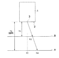
まず、図1を用いて各ノズルの着弾位置ずれ量を把握する方法を説明する。図1において、符号1は記録ヘッド、2はインク吐出面(ノズル面)を表す。ここでは、1つのノズル3(i番目のノズル)に注目して、その着弾位置ずれを考察するが、記録ヘッド1のノズル面2には、複数のノズルが形成されている。また、図1中符号Aは測定の基準となる媒体の記録面(第1の記録面に相当)を示し、符号Bは記録しようとする媒体の記録面(第2の記録面に相当)を示す。
[How to determine the amount of landing position deviation]
First, a method of grasping the landing position deviation amount of each nozzle will be described with reference to FIG. In FIG. 1,
テストパターンの印刷を実施する媒体Aとノズル面2間の距離(第1の距離に相当)をYaとし、媒体Aに対して所定のテスト印刷を行い、その印刷結果を測定する。i番目のノズル3の媒体Aに対する理想着弾位置をX0とし、ノズル3からの打滴の斜め飛翔によって生じる着弾位置のずれ量(理想着弾位置X0からの着弾位置誤差)をXaiとする。こうして、ノズル面2−媒体A間距離Yaと、着弾位置ずれ量Xaiの情報を得る。
A distance between the medium A on which the test pattern is printed and the nozzle surface 2 (corresponding to the first distance) is set to Ya, a predetermined test printing is performed on the medium A, and the printing result is measured. The ideal landing position of the i-
実際に記録しようとする媒体Bとノズル面2間の距離(第2の距離に相当)をYbとすると(ただし、Yb<Ya)、媒体Bで予測される着弾位置ずれ量Xbiは、次式
[数2] Xbi=(Yb/Ya)×Xai
として求められる。
When the distance between the medium B to be actually recorded and the nozzle surface 2 (corresponding to the second distance) is Yb (where Yb <Ya), the landing position deviation amount Xbi predicted by the medium B is expressed by the following equation: [Formula 2] Xbi = (Yb / Ya) × Xai
As required.
このXbiに基づいて打滴配置の補正(詳細は後述)を行う。 Based on this Xbi, the droplet ejection arrangement is corrected (details will be described later).
着弾位置ずれの測定用テストパターンをプリントし、これを測定するタイミングとしては、例えば、記録ヘッドのメンテナンス動作後に実施する態様がある。メンテナンス動作では、ノズル3の吸引やノズル面2のワイピングによって、ノズル面2のインクミストやゴミが取り除かれるため、メンテナンス作業の前後で着弾位置ずれが大きく変化することがある。したがって、メンテナンス動作後に着弾位置ずれの測定を行う態様が好ましい。
As a timing for printing a test pattern for measuring landing position deviation and measuring it, for example, there is an embodiment in which it is performed after a maintenance operation of the recording head. In the maintenance operation, because the ink mist and dust on the
ただし、必ずしも毎回のメンテナンス動作後の測定は必要とされない。ノズル近傍の撥水膜の劣化や傷による斜め飛翔は固定的な現象(時間による変動の少ない現象)であるため、これらが支配要因である場合は、装置の起動時、或いは1日〜1週間間隔程度で測定を実施する態様でもよい。なお、インクの特性や環境の影響によってノズル近傍へのインクミストやゴミの付着が顕著な場合は、測定頻度を上げることが好ましい。 However, measurement after every maintenance operation is not necessarily required. Diagonal flight due to deterioration or scratches in the water-repellent film near the nozzle is a fixed phenomenon (a phenomenon with little fluctuation due to time), so when these are the controlling factors, when the apparatus is started or from 1 day to 1 week An embodiment in which measurement is performed at intervals is also possible. In the case where ink mist or dust adheres to the vicinity of the nozzle due to ink characteristics or environmental influences, it is preferable to increase the measurement frequency.
着弾位置ずれ量の測定には、テストプリントの印字結果を撮像するためのイメージセンサ(ラインセンサ又はエリアセンサ)を具備する印字検出手段(例えば、CCDスキャナー)を用いる。印字検出手段にてテストパターンを読み取り、得られた画像信号を解析(処理)して、着弾位置ずれ量Xaiを求める。 For the measurement of the amount of landing position deviation, a print detection means (for example, a CCD scanner) including an image sensor (line sensor or area sensor) for imaging the print result of the test print is used. The test pattern is read by the print detecting means, and the obtained image signal is analyzed (processed) to obtain the landing position deviation amount Xai.
テストパターン印字用の媒体Aは、にじみの程度が弱い媒体(例えば多孔質の受像層を有する媒体、インクジェット専用写真用紙など)とすることが好ましい。このような、媒体を用いることで、きれいなドット形状が媒体状で再現されるため、着弾位置ずれの測定精度が上がる。 The test pattern printing medium A is preferably a medium with a low degree of bleeding (for example, a medium having a porous image receiving layer, an inkjet-dedicated photographic paper, or the like). By using such a medium, a beautiful dot shape is reproduced in a medium shape, so that the measurement accuracy of the landing position deviation is increased.
或いはまた、記録媒体を保持・搬送するための搬送ベルト自体を媒体Aとして兼用する態様も可能である。すなわち、テストパターンを搬送ベルト上に直接プリントする態様も可能である。この場合、無駄な媒体が消費されないという利点があることに加え、次のような利点もある。搬送ベルト上にテストパターンをプリントする態様は、打滴の飛翔距離が最も長くなるため、斜め飛翔による着弾位置ずれ量も大きくなる(搬送ベルト上にテスト印刷用の媒体を載せる場合、媒体の厚み分だけ飛翔距離は短くなるので、何も載せない搬送ベルト上にプリントする場合にYaは最大となる)。したがって、印字検出部での着弾位置ずれ量の測定が容易となる。また、装置の所定位置に印字検出手段を取り付けた構成の場合、当該印字検出手段のセンサによる観察距離が固定値(センサ−ベルト間距離が固定値)になるため、印字検出手段における光学式センサの焦点深度は浅くてよい。 Alternatively, a mode in which the conveyance belt for holding and conveying the recording medium is also used as the medium A is possible. That is, a mode in which the test pattern is directly printed on the conveyance belt is also possible. In this case, in addition to the advantage that a useless medium is not consumed, there are also the following advantages. Since the test pattern is printed on the conveyor belt, the landing distance of the droplets is the longest, so the amount of landing position deviation due to oblique flight also increases (if a test print medium is placed on the conveyor belt, the thickness of the medium Since the flight distance is shortened by that amount, Ya is maximized when printing on a transport belt on which nothing is placed. Accordingly, it is easy to measure the amount of landing position deviation in the print detection unit. In the case where the print detection means is mounted at a predetermined position of the apparatus, the observation distance by the sensor of the print detection means is a fixed value (the distance between the sensor and the belt is a fixed value). The depth of focus may be shallow.
ノズル面−媒体間距離の測定には、例えば、パルスレーザによって距離測定を行う測距手段を用いることができる。また、媒体の厚み情報をユーザインターフェースから与えてもよい。この場合、更に、テストパターンを搬送ベルト上にプリントすればYaを固定値に設計できることから、距離の測定が不要となり(Yaと媒体の厚みからYbを計算できるため)、ノズル面−媒体間距離を測定するための測定手段(測定装置)を省略する装置構成も可能である。 For the measurement of the distance between the nozzle surface and the medium, for example, a distance measuring unit that performs distance measurement using a pulse laser can be used. Further, the thickness information of the medium may be given from the user interface. In this case, if the test pattern is further printed on the conveyance belt, Ya can be designed to be a fixed value, so that measurement of the distance becomes unnecessary (because Yb can be calculated from Ya and the thickness of the medium), and the distance between the nozzle surface and the medium It is also possible to adopt a device configuration in which measurement means (measuring device) for measuring is omitted.
〔処理フロー〕
図2は、画像処理の手順を示したフローチャートである。なお、処理の前提として、予めYaとXaiは過去に測定されていて、その情報はメモリ等の記憶手段に記憶されているものとする。
[Process flow]
FIG. 2 is a flowchart showing a procedure of image processing. As a premise of processing, it is assumed that Ya and Xai have been measured in the past in advance and the information is stored in storage means such as a memory.
図示のように、まず、印字しようとする媒体(プリント媒体)Bとノズル面間の距離Ybの情報を獲得する(ステップS11)。既述のとおり、レーザを利用した測距手段などによって実際に距離の測定を行うことでYbの情報を取得してもよいし、ユーザインターフェースから媒体Bの厚み情報を入力することで距離Ybの情報を与えてもよい。 As shown in the figure, first, information on the distance Yb between the medium (print medium) B to be printed and the nozzle surface is acquired (step S11). As described above, Yb information may be acquired by actually measuring the distance by a distance measuring means using a laser, or the thickness information of the medium B is input from the user interface. Information may be given.
次いで、注目するノズル番号を表すパラメータiの値を1に設定(初期化)する(ステップS12)。その後、ステップS13に進み、iの値が記録ヘッドの総ノズル数nを超えたか否かを判定する。 Next, the value of the parameter i indicating the nozzle number of interest is set to 1 (initialized) (step S12). Thereafter, the process proceeds to step S13, and it is determined whether or not the value of i exceeds the total number n of nozzles of the print head.
iの値がnを超えていない場合には、ステップS14に進み、媒体Bでの着弾位置ずれ量Xbiを、上述の〔数2〕で示した計算式に従って求める演算を行う。このとき、予め記憶されているYa、Xaiの情報が活用される。ステップS14で求めたXbiの情報はメモリ等の記憶手段に記憶(保存)される。その後、ステップS15で注目ノズル番号iの値を「1」増加させて(iの値をインクリメントして)から、ステップS13に戻る。 When the value of i does not exceed n, the process proceeds to step S14, and the calculation for obtaining the landing position deviation amount Xbi on the medium B is performed according to the calculation formula shown in the above [Equation 2]. At this time, pre-stored information on Ya and Xai is utilized. The Xbi information obtained in step S14 is stored (saved) in storage means such as a memory. Thereafter, in step S15, the value of the nozzle number i of interest is increased by “1” (the value of i is incremented), and then the process returns to step S13.
ステップS13〜S15の処理を繰り返し、全てのノズル(i=1〜n)について着弾位置ずれ量Xbiを計算する。全てのノズル(i=1〜n)について着弾位置ずれ量Xbiを計算し終えると、ステップS13の判定においてi>nとなり、ステップS16に進む。 The processes of steps S13 to S15 are repeated, and the landing position deviation amount Xbi is calculated for all nozzles (i = 1 to n). When calculation of the landing position deviation amount Xbi is completed for all nozzles (i = 1 to n), i> n in the determination of step S13, and the process proceeds to step S16.
ステップS16では、上記求めたXbi(i=1〜n)を用いて各ノズルの濃度補正係数di(i=1〜n)を求める。次いで、プリント対象の入力画像のデータを濃度補正係数di(i=1〜n)に基づいて補正し(ステップS17)、その補正後のデータを用いて中間階調処理(ハーフトーニング処理)を行い、打滴配置データを求める(ステップS18)。 In step S16, the density correction coefficient di (i = 1 to n) of each nozzle is obtained using the obtained Xbi (i = 1 to n). Next, the input image data to be printed is corrected based on the density correction coefficient di (i = 1 to n) (step S17), and halftone processing (halftoning processing) is performed using the corrected data. Then, droplet placement data is obtained (step S18).
こうして、求めた打滴配置データに基づいて記録ヘッドの各ノズルの吐出動作が制御される。 Thus, the ejection operation of each nozzle of the recording head is controlled based on the obtained droplet placement data.
ここで、上記ステップS16〜S18の補正処理の一例について、以下に説明する。 Here, an example of the correction process in steps S16 to S18 will be described below.
〔打滴配置の補正原理〕
本実施形態による打滴配置の補正処理では、あるノズルが持つ着弾位置誤差(着弾位置ずれ)を補正する際に、そのノズルを含む周囲のノズルN本を用いて補正する。詳細は後述するが、補正に用いるノズル数Nが大きいほど、より補正精度が高くなる。
[Droplet placement correction principle]
In the droplet placement correction process according to the present embodiment, when a landing position error (landing position deviation) of a nozzle is corrected, correction is performed using N surrounding nozzles including the nozzle. Although details will be described later, the correction accuracy increases as the number N of nozzles used for correction increases.
図3は補正前の様子を示す図である。同図は、ラインヘッド(記録ヘッドに相当)10の左から3番目のノズル(nzl3)が着弾位置誤差を持っており、理想的な着弾位置(原点O)から図上で右方向(X軸で示した主走査方向)に着弾位置がずれて着弾する。また、図3の下側に示したグラフは、ノズルからの打滴による印字濃度を被記録媒体搬送方向(副走査方向)に平均化して得られる、ノズル列方向(主走査方向)の濃度プロファイルを示したものである。ただし、図3ではノズルnzl3の印字に対する補正を考察するので、ノズルnzl3以外の濃度出力は図示を省略した。 FIG. 3 shows a state before correction. The figure shows that the third nozzle (nzl3) from the left of the line head (corresponding to the recording head) 10 has a landing position error, and it moves to the right (X axis) from the ideal landing position (origin O). The landing position is shifted in the main scanning direction shown in FIG. 3 is a density profile in the nozzle row direction (main scanning direction) obtained by averaging the print density due to droplet ejection from the nozzles in the recording medium conveyance direction (sub-scanning direction). Is shown. However, in FIG. 3, since correction for printing of the nozzle nzl3 is considered, the density output other than the nozzle nzl3 is not shown.
各ノズルnzl1〜5の初期出力濃度をDi=Dini(ただし、iはノズル番号1〜5、Diniは一定値を表す)、ノズルnzl3の理想着弾位置を原点O、各ノズルnzl1〜5の着弾位置をXi とする。 The initial output density of each nozzle nzl1-5 is Di = Dini (where i is the nozzle number 1-5, Dini is a constant value), the ideal landing position of nozzle nzl3 is the origin O, and the landing position of each nozzle nzl1-5 Is Xi.
ここでDi は、物理的には記録媒体搬送方向に平均化したノズルの出力光学濃度を表し、データ処理上は各画素が持つ濃度データD(i,j) (ただし、iはノズル番号、jは記録媒体搬送方向の画素番号を表す)に対して「j」について平均化したものを表している。 Here, Di represents the output optical density of the nozzles physically averaged in the recording medium conveyance direction, and in data processing, density data D (i, j) (where i is the nozzle number, j Represents an average of “j” with respect to the pixel number in the recording medium conveyance direction).
図3に示したように、ノズルnzl3の着弾位置誤差は、ノズルnzl3の濃度出力(太線)の原点Oからのズレとして表される。今、この出力濃度のズレを補正することを考える。 As shown in FIG. 3, the landing position error of the nozzle nzl3 is expressed as a deviation from the origin O of the density output (thick line) of the nozzle nzl3. Now, let us consider correcting this deviation in output density.
図4は補正後の様子を示す図である。ただし、ノズルnzl3以外は補正分のみを図示した。図4の場合、補正に用いるノズル数はN=3であり、ノズルnzl2, nzl3, nzl4 に濃度補正係数d2, d3, d4 が乗ぜられている。ここでいう濃度補正係数di は、補正後の出力濃度をDi’とするとき、Di’=Di+di×Diで定義される係数である。 FIG. 4 is a diagram showing a state after correction. However, only the correction amount is illustrated except for the nozzle nzl3. In the case of FIG. 4, the number of nozzles used for correction is N = 3, and density correction coefficients d2, d3, d4 are multiplied by the nozzles nzl2, nzl3, nzl4. The density correction coefficient di here is a coefficient defined by Di '= Di + di * Di, where Di' is the corrected output density.
本実施形態では、濃度ムラの視認性が最小となるよう、各ノズルの濃度補正係数di が決定される。印字画像の濃度ムラは、空間周波数特性(パワースペクトル)での強度で表される。人間の視覚的には高周波成分は視認できないため、濃度ムラ野視認性は、パワースペクトルの低周波成分に等しい。そのため、パワースペクトルの低周波成分を最小とするよう、各ノズルの濃度補正係数di が決定される。 In the present embodiment, the density correction coefficient di for each nozzle is determined so that the visibility of density unevenness is minimized. The density unevenness of the printed image is expressed by the intensity in the spatial frequency characteristic (power spectrum). Since the high frequency component cannot be visually recognized by humans, the density unevenness visibility is equal to the low frequency component of the power spectrum. Therefore, the density correction coefficient di of each nozzle is determined so as to minimize the low frequency component of the power spectrum.
濃度補正係数diを決定する式の導出について詳細は後述するが、結果のみを先に示すと、特定のノズルの着弾位置誤差に対する濃度補正係数diは、以下の式より決定される。 Although the details of the derivation of the equation for determining the density correction coefficient di will be described later, when only the result is shown first, the density correction coefficient di for the landing position error of a specific nozzle is determined by the following formula.
ここで、xi はそれぞれ補正対象ノズルの理想着弾位置を原点とした各ノズルの着弾位置である。本実施形態の場合、図1〜2で説明した「Xbi」がこれに相当する。〔数3〕の式中のΠは、補正に用いるN本のノズル内で積をとることを意味する。図4におけるN=3の場合について明示的に表すと、次のようになる。 Here, x i is the landing position of each nozzle with the ideal landing position of the correction target nozzle as the origin. In the present embodiment, “Xbi” described with reference to FIGS. Π in the equation (3) means that the product is taken in N nozzles used for correction. The case where N = 3 in FIG. 4 is explicitly expressed is as follows.
〔濃度補正係数の導出〕
濃度ムラのパワースペクトルの低周波成分を最小化するという条件から、理論的に各ノズルの濃度補正係数を導くことができる。
[Derivation of density correction coefficient]
From the condition of minimizing the low frequency component of the power spectrum of density unevenness, the density correction coefficient of each nozzle can be theoretically derived.
まず、各ノズルの誤差特性を取り込んだ濃度プロファイルを次式のように定義する。 First, a density profile incorporating the error characteristics of each nozzle is defined as follows:
画像の濃度プロファイルD(x)は、各ノズルが印字する濃度プロファイルの和であり、ノズルの印字を表すのが印字モデル(1ノズルが印字する濃度プロファイル)である。印字モデルはノズル出力濃度Diと標準濃度プロファイルz(x)に分離して表現される。 The density profile D (x) of the image is the sum of the density profiles printed by each nozzle, and the printing model (density profile printed by one nozzle) represents the printing of the nozzles. The print model is expressed separately as a nozzle output density Di and a standard density profile z (x).
標準濃度プロファイルz(x)は、厳密にはドット系に等しい有限の広がりを持つものであるが、位置誤差の補正を濃度ズレのバランシングの問題であると考えると、重要なのは濃度プロファイルの重心位置(着弾位置)であって、濃度プロファイルの広がりは副次的な要素である。そのため、プロファイルをδ関数で置き換える近似は妥当である。このような標準濃度プロファイルを仮定すると数学的な取り扱いが容易となり、補正係数の厳密解が得られる。 Strictly speaking, the standard density profile z (x) has a finite spread equal to that of the dot system. However, considering the correction of the position error as a problem of density deviation balancing, the important point is the position of the center of gravity of the density profile. The (landing position) and the spread of the density profile is a secondary factor. Therefore, an approximation that replaces the profile with a δ function is reasonable. Assuming such a standard concentration profile, mathematical handling becomes easy and an exact solution of the correction coefficient is obtained.
図5(a)は現実に即した印字モデルであり、図5(b)はδ関数型印字モデルである。δ関数モデルで近似する場合、標準濃度プロファイルは次式で表される。 FIG. 5A shows a printing model that is realistic, and FIG. 5B shows a δ function type printing model. When approximated by the δ function model, the standard concentration profile is expressed by the following equation.
![]()
![]()
補正係数を導出するにあたり、ある特定のノズル(i=0)の着弾位置誤差Δx0を、周辺ノズルN本によって補正することを考える。なお、ここでは補正対象ノズルの番号をi=0とした。また、周辺のノズルも、所定の着弾位置誤差を持ち得ることに注意する。 Upon deriving the correction factor, a depositing position error [Delta] x 0 of a particular nozzle (i = 0), considering that to correct by surrounding the nozzle N present. Here, the correction target nozzle number is i = 0. Note that peripheral nozzles can also have a predetermined landing position error.
補正対象ノズル(中心ノズル)を含むN本のノズルの番号(index)は、次式で表される。 The number (index) of the N nozzles including the correction target nozzle (center nozzle) is expressed by the following equation.
なお、この式においては、Nは奇数である必要があるが、本発明の実施に際しては、Nを奇数に限定する必要はない。 In this equation, N needs to be an odd number, but it is not necessary to limit N to an odd number when implementing the present invention.
初期出力濃度(補正前の出力濃度)はi=0のみ値を持つものとして、次式で表される。 The initial output density (output density before correction) is expressed by the following equation assuming that only i = 0 has a value.
濃度補正係数をdiとするとき、補正後出力濃度Di’は、次式で表される。 When the density correction coefficient is di, the corrected output density Di 'is expressed by the following equation.
つまり、i=0では初期出力濃度値と補正値(di×Dini)の和で表され、i≠0では補正値のみとなる。 That is, when i = 0, it is represented by the sum of the initial output density value and the correction value (di × Dini), and when i ≠ 0, only the correction value is obtained.
各ノズルiの着弾位置xiは、次式で表される。 Impact position x i of each nozzle i is expressed by the following equation.
δ関数型印字モデルを用いると、補正後の濃度プロファイルは、次式で表される。 When the δ function type printing model is used, the corrected density profile is expressed by the following equation.
これに対してFourier変換を行うと、次式、 On the other hand, when performing Fourier transform,
と表される。なお、Diniは共通の定数のため省略した。 It is expressed. Dini is omitted because it is a common constant.
濃度ムラの視認性を最小化することは、すなわち、次式のパワースペクトルの低周波成分を最小化することである。 Minimizing the visibility of density unevenness is to minimize the low frequency component of the power spectrum of the following equation.
これは、数学的にはT(f)の f=0における微分係数(1次、2次、…)がゼロであることで近似できる。今、未知数di’はN個であるから、DC成分の保存条件も含めると、N−1次までの微分係数がゼロの条件を用いれば、全ての(N個の)未知数di’が厳密に定まる。このようにして、以下の補正条件が定まる。 This can be mathematically approximated by the fact that the differential coefficient (first order, second order,...) Of T (f) at f = 0 is zero. Since the number of unknowns di ′ is now N, if the condition for storing the DC component is included, all (N) unknowns di ′ are strictly determined by using the condition that the differential coefficient up to the N−1 order is zero. Determined. In this way, the following correction conditions are determined.
δ関数モデルにおいては、各補正条件を展開していくと、容易な計算によってDiについてのN本の連立方程式に帰着する。各補正条件を展開したものを整理すると、以下の条件群(方程式群)が得られる。 In the δ function model, when each correction condition is developed, it is reduced to N simultaneous equations for Di by easy calculation. Arranging the development of each correction condition gives the following condition group (equation group).
これらの方程式群の意味するところは、1式目はDC成分の保存であり、2式目は重心位置の保存を表している。3式目以降は統計学におけるN−1次モーメントがゼロであることを表している。 The meaning of these equations is that the first equation represents preservation of the DC component, and the second equation represents preservation of the center of gravity. The third and subsequent formulas indicate that the N-1th moment in statistics is zero.
このようにして得られた条件式を行列形式で表すと、以下のように表すことができる。 When the conditional expression thus obtained is expressed in matrix form, it can be expressed as follows.
この係数行列Aは、いわゆるVandermonde型の行列であり、その行列式は差積を用いて次式となることが知られている。 This coefficient matrix A is a so-called Vandermonde type matrix, and its determinant is known to be the following expression using a difference product.
このため、Crammerの公式を用いてdi’の厳密解を求めることができる。計算の詳細な過程は省略するが、代数計算によって、その解は次式となることが示される。 For this reason, the exact solution of di 'can be obtained using Cramer's formula. The detailed process of the calculation is omitted, but the algebraic calculation shows that the solution is
よって、求めるべき補正係数diは、次式となる。 Therefore, the correction coefficient di to be obtained is as follows.
以上のように、パワースペクトルの原点微分係数をゼロにするという条件から、濃度補正係数diの厳密解が導かれる。補正に用いる周辺ノズル数Nを増やすほど、より高次の微分係数をゼロにすることが可能になるため、低周波エネルギーがより小さくなり、ムラの視認性は一層低減する。 As described above, the exact solution of the density correction coefficient di is derived from the condition that the origin differential coefficient of the power spectrum is zero. As the number N of peripheral nozzles used for correction is increased, the higher-order differential coefficient can be made zero, so that the low frequency energy becomes smaller and the visibility of unevenness is further reduced.
本実施形態では、微分係数をゼロにする条件を用いたが、完全にゼロとせずとも、補正前の微分係数に比べて十分小さい値(例えば、補正前の1/10)に設定しても、ムラ低減可能である。 In the present embodiment, the condition for setting the differential coefficient to zero is used. However, even if it is not completely zero, it may be set to a value sufficiently smaller than the differential coefficient before correction (for example, 1/10 before correction). Unevenness can be reduced.
〔上記濃度補正係数を用いる補正の効果〕
図6は、図3に示した着弾位置誤差を持つノズルに対して、補正後の空間周波数特性(パワースペクトル)を示したものである。図6では補正無しの場合と、N=3のときの補正例1と、N=5のときの補正例2が示されている。計算上の共通の条件として、ドット密度:1200dpi、ドットの着弾径:32μm、ノズル位置誤差(着弾位置誤差):10μmを用いた。
[Effect of correction using the above density correction coefficient]
FIG. 6 shows the corrected spatial frequency characteristic (power spectrum) for the nozzle having the landing position error shown in FIG. FIG. 6 shows the case of no correction, correction example 1 when N = 3, and correction example 2 when N = 5. As common conditions for calculation, dot density: 1200 dpi, dot landing diameter: 32 μm, nozzle position error (landing position error): 10 μm were used.
人間の視覚特性を考慮すると、濃度ムラの視認性を示すのは、0〜8cycle/mmの低周波領域であり、この領域のパワースペクトルが小さいほど、補正精度が高いことを意味する。 Considering human visual characteristics, the visibility of density unevenness is in a low frequency region of 0 to 8 cycles / mm, and the smaller the power spectrum in this region, the higher the correction accuracy.
補正例1(N=3)は、0〜5cycle/mmでほぼパワースペクトルがゼロであり、補正無しの場合と比較して、十分に補正効果を有していることを示している。また、補正例2(N=5)は、補正例1(N=3)に比べてさらにパワースペクトルが低下している。このことより、補正に用いるノズル数Nを増やすほど、補正効果の向上が認められる。なお、本例(図3)の場合、図7に示すように、補正対象ノズルnzl3の出力濃度は、物理的にはarea1、area5にはみ出していないが、ノズルnzl1、nzl5も補正に用いることで、よりパワースペクトルを低下させることができる。 Correction example 1 (N = 3) shows that the power spectrum is almost zero at 0 to 5 cycle / mm, and has a sufficient correction effect as compared with the case without correction. In addition, the power spectrum of the correction example 2 (N = 5) is lower than that of the correction example 1 (N = 3). Accordingly, the correction effect is improved as the number N of nozzles used for correction is increased. In the case of this example (FIG. 3), as shown in FIG. 7, the output density of the correction target nozzle nzl3 does not physically protrude from area1 and area5, but the nozzles nzl1 and nzl5 are also used for correction. , The power spectrum can be further reduced.
図8は、補正に用いるノズル数を変えた各補正例1〜3の濃度補正係数を比較したものである。N=3のときの補正例1、N=5のときの補正例2、N=7のときの補正例3を比較するとわかるように、N値が増加するほど補正精度は向上するが、濃度補正係数の変化幅も大きくなる。また、当然ながらノズルの着弾位置誤差が増大するほど、濃度補正係数の変化幅も大きくなる。 FIG. 8 compares the density correction coefficients of correction examples 1 to 3 in which the number of nozzles used for correction is changed. As can be seen from a comparison between correction example 1 when N = 3, correction example 2 when N = 5, and correction example 3 when N = 7, the correction accuracy improves as the N value increases. The variation range of the correction coefficient is also increased. As a matter of course, as the landing position error of the nozzle increases, the variation range of the density correction coefficient increases.
濃度補正係数がある一定以上増加すると、入力画像の再現を破綻させる可能性があるため好ましくない。したがって、必要以上のN値の増加は好ましくない。補正精度と画像再現性の観点を踏まえて最適なN値を設定することが望ましい。なお、図8で示したN=3〜7の各補正例1〜3は、いずれの場合も濃度補正係数の変化幅(絶対値)は比較的小さいく、入力画像の再現を破綻させることなく、濃度ムラの補正が可能である。 If the density correction coefficient increases by a certain value or more, there is a possibility that the reproduction of the input image may be broken, which is not preferable. Therefore, an increase in N value more than necessary is not preferable. It is desirable to set an optimal N value in view of correction accuracy and image reproducibility. In each of the correction examples 1 to 3 with N = 3 to 7 shown in FIG. 8, the change width (absolute value) of the density correction coefficient is relatively small in any case, and the reproduction of the input image is not broken. The density unevenness can be corrected.
上記説明は、ある特定の1ノズル(例えば、図3におけるノズルnzl3)に対する濃度補正係数の決定方法である。実際には、ヘッド内の全てのノズルが何らかの着弾位置誤差を持っているため、全ての着弾位置誤差に対して補正を行うことが好ましい。 The above description is a method for determining the density correction coefficient for one specific nozzle (for example, the nozzle nzl3 in FIG. 3). Actually, since all the nozzles in the head have some landing position error, it is preferable to correct all the landing position errors.
すなわち、全てのノズルに対して、周囲N個のノズルにおける上記の濃度補正係数を求める。濃度補正係数を決定する際に用いる後述のパワースペクトル最小化方程式は線形なので、ノズルごとに重ね合わせが可能である。そのため、トータルの濃度補正係数は、上述のようにして得られた濃度補正係数の和を取れば求められる。 That is, the density correction coefficients for the N surrounding nozzles are obtained for all nozzles. Since a power spectrum minimization equation (to be described later) used for determining the density correction coefficient is linear, it can be superposed for each nozzle. Therefore, the total density correction coefficient can be obtained by taking the sum of the density correction coefficients obtained as described above.
つまり、ノズルkの持つ位置誤差に対するノズルiの濃度補正係数をd(i,k)とおくと、このd(i,k)は〔数3〕の方程式で求められる。そして、ノズルiのトータルの濃度補正係数diは、次式として求められる。 That is, if the density correction coefficient of the nozzle i with respect to the position error of the nozzle k is d (i, k), this d (i, k) is obtained by the equation [Equation 3]. The total density correction coefficient di of the nozzle i is obtained as the following equation.
なお、上記の例では、全ノズルの着弾位置誤差を補正対象としてインデックスkを足し合わせているが、ある値ΔX_threshを閾値として予め設定しておき、この閾値を超える着弾位置誤差をもつノズルのみを補正対象とするように選択的に補正する構成も可能である。 In the above example, the index k is added with the landing position errors of all nozzles as correction targets. However, a certain value ΔX_thresh is preset as a threshold value, and only nozzles having landing position errors exceeding this threshold value are set. A configuration in which correction is selectively performed so as to be a correction target is also possible.
前述のとおり、補正に用いるノズル数Nの値を増加させると補正精度が向上するが、濃度補正係数の変化幅も増加して再現画像の破綻を招く可能性がある。そのため、画像破綻を起こさないための補正係数制限範囲(上限値d_maxと下限値d_min)を定めておき、上記〔数20〕の式で求まるトータルの濃度補正係数が制限範囲内に収まるようにN値を設定することが望ましい。すなわち、d_min<di<d_maxを満たすようN値を定める。 As described above, when the number N of nozzles used for correction is increased, the correction accuracy is improved. However, the change width of the density correction coefficient is also increased, and there is a possibility that the reproduced image is broken. For this reason, a correction coefficient limit range (upper limit value d_max and lower limit value d_min) for preventing image corruption is determined, and N is set so that the total density correction coefficient obtained by the above equation (20) falls within the limit range. It is desirable to set a value. That is, the N value is determined so as to satisfy d_min <di <d_max.
実験的な知見によれば、d_min≧−1、d_max≦1を満たすならば画像破綻を起こさない。 According to experimental knowledge, image failure does not occur if d_min ≧ −1 and d_max ≦ 1.
〔画像処理フロー〕
本実施形態によるムラ補正処理の実装を含めた画像処理フローを図9に示す。
[Image processing flow]
FIG. 9 shows an image processing flow including implementation of unevenness correction processing according to the present embodiment.
入力画像20のデータ形態は、特に限定されないが、例えば、24bitのRGBデータとする。この入力画像20に対して、ルックアップテーブルによる濃度変換処理を行い(ステップS22)、プリンタの持つインク色に対応した濃度データD(i,j)に変換する。なお、(i,j)は画素の位置を表し、各画素について濃度データが割り当てられる。
The data format of the
ここでは、入力画像20の解像度とプリンタの解像度(ノズル解像度)は一致しているものとする。なお、両者が一致しない場合は、プリンタ解像度に合わせて、入力画像について画素数変換の処理が行われる。
Here, it is assumed that the resolution of the
ステップS22における濃度変換処理は一般的な処理であり、下色除去(UCR:Undercolor Removal)処理、或いはライトインク(同色系の淡インク)を使用するシステムの場合におけるライトインクへの分配処理などが含まれる。 The density conversion process in step S22 is a general process, such as an undercolor removal (UCR) process or a distribution process to light ink in the case of a system that uses light ink (same color light ink). included.
例えば、C(シアン)M(マゼンタ)Y(イエロー)の3色インクの構成の場合には、CMYの濃度データD(i,j)に変換される。或いはまた、上記3色に加えてK(黒),LC(ライトシアン),LM(ライトマゼンタ)などの他のインクを含むシステムの場合は、そのインク色を含む濃度データD(i,j)に変換される。 For example, in the case of a three-color ink configuration of C (cyan), M (magenta), and Y (yellow), it is converted into CMY density data D (i, j). Alternatively, in the case of a system including other inks such as K (black), LC (light cyan), and LM (light magenta) in addition to the above three colors, the density data D (i, j) including the ink color is included. Converted.
濃度変換処理を経て得られた濃度データD(i,j)(図9中の符号30)に対してムラ補正処理が行われる(ステップS32)。ここでは、対応するノズルに応じた濃度補正係数(打滴率補正係数)diを濃度データD(i,j)に乗ずる演算が行われる。 Unevenness correction processing is performed on the density data D (i, j) (reference numeral 30 in FIG. 9) obtained through the density conversion processing (step S32). Here, calculation is performed by multiplying the density data D (i, j) by the density correction coefficient (droplet ejection rate correction coefficient) di corresponding to the corresponding nozzle.
図10の模式図に示したように、ノズルnzliの位置(主走査方向位置)iと副走査方向位置jによって画像上の画素位置(i,j)が特定され、各画素について濃度データD(i,j)が与えられる。今、図10の斜線で示した画素列の打滴を受け持つノズルについてムラ補正処理を行う場合、補正後の濃度データD’(i,j)は次式、
D’(i,j)=D(i,j)+di×D(i,j)
で計算される。こうして、補正済みの濃度データD’(i,j)が得られる。
As shown in the schematic diagram of FIG. 10, the pixel position (i, j) on the image is specified by the position (main scanning direction position) i and the sub-scanning direction position j of the nozzle nzli, and density data D ( i, j). When the unevenness correction processing is performed for the nozzles responsible for droplet ejection in the pixel rows indicated by the diagonal lines in FIG. 10, the corrected density data D ′ (i, j) is expressed by the following equation:
D ′ (i, j) = D (i, j) + di × D (i, j)
Calculated by In this way, corrected density data D ′ (i, j) is obtained.
この補正済みの濃度データD’(i,j)(図9中の符号40)からハーフトーニング処理を行うことによって(ステップS42)、ドットのオン/オフ信号(2値データ)、または、ドットサイズ変調を含む場合はサイズの種類(ドットサイズの選択)を含んだ多値データに変換される。ハーフトーニングの手法は特に限定されず、誤差拡散法やディザ法など周知の2値(多値)化手法を用いることができる。
By performing halftoning processing from the corrected density data D ′ (i, j) (
このようにして得られた2値(多値)信号(図9の符号50)に基づいて各ノズルのインク吐出(打滴)データが生成され、吐出動作が制御される。これにより、濃度ムラが抑制され、高品位な画像形成が可能である。
Based on the binary (multilevel) signal (
図11は、濃度補正係数(補正データ)の更新処理の例を示したフローチャートである。補正データの更新処理は、例えば、以下のいずれかの条件で開始される。 FIG. 11 is a flowchart illustrating an example of a density correction coefficient (correction data) update process. The correction data update process is started, for example, under any of the following conditions.
すなわち、(a)印字結果を監視する自動チェック機構(センサ)によって印字画像にスジムラが生じていると判断された場合、(b)人間(オペレータ)が印字画像を見て画像内にスジムラが生じていると判断して所定の操作(更新処理を開始させる指令の入力など)を行った場合、(c)事前に設定していた更新タイミングに達した場合(タイマー等による時間管理やプリント枚数カウンタなどによる稼働実績管理などによって更新タイミングを設定並びに判断可能)、のいずれかの条件で図示の更新処理がスタートする。 That is, (a) when it is determined by the automatic check mechanism (sensor) that monitors the print result that the print image is uneven, (b) a human (operator) sees the print image and the image is uneven. (C) When the update timing set in advance is reached (time management by a timer or the like and a print sheet counter) The update process shown in the figure is started under any of the following conditions: the update timing can be set and determined by the operation result management or the like.
更新処理がスタートすると、まず、着弾誤差データを測定するためのテストパターン(予め定められている所定のパターン)のプリントが実行される(ステップS70)。 When the update process starts, first, a test pattern (predetermined predetermined pattern) for measuring the landing error data is printed (step S70).
次いで、そのテストパターンの印字結果から着弾誤差データを測定する(ステップS72)。着弾誤差データの測定には、イメージセンサ(撮像素子)を利用した画像読取装置(撮像信号を処理する信号処理手段を含む)を用いることができる。着弾誤差データには、着弾位置誤差の情報及び光学濃度情報などが含まれる。 Next, landing error data is measured from the printing result of the test pattern (step S72). For the measurement of the landing error data, an image reading apparatus (including a signal processing means for processing an imaging signal) using an image sensor (imaging element) can be used. The landing error data includes landing position error information and optical density information.
そして、ステップS72で得られた着弾誤差データから補正データ(濃度補正係数)が算出される(ステップS74)。濃度補正係数の算出方法については、既に説明した通りである。 Then, correction data (density correction coefficient) is calculated from the landing error data obtained in step S72 (step S74). The method for calculating the density correction coefficient has already been described.
こうして、求めた濃度補正係数の情報はEEPROM等の書き換え可能な記憶手段に記憶され、以後、最新の補正係数が用いられる。 Thus, the obtained density correction coefficient information is stored in a rewritable storage means such as an EEPROM, and the latest correction coefficient is used thereafter.
〔インクジェット記録装置の構成〕
次に、上述した濃度ムラの補正機能を備えた画像記録装置の具体的な適用例としてのインクジェット記録装置について説明する。
[Configuration of inkjet recording apparatus]
Next, an ink jet recording apparatus will be described as a specific application example of the image recording apparatus having the above-described density unevenness correction function.
図12は、本発明に係る画像記録装置の一実施形態を示すインクジェット記録装置の全体構成図である。同図に示すように、このインクジェット記録装置110は、黒(K),シアン(C),マゼンタ(M),イエロー(Y)の各インクに対応して設けられた複数のインクジェット記録ヘッド(以下、ヘッドという。)112K,112C,112M,112Yを有する印字部112と、各ヘッド112K,112C,112M,112Yに供給するインクを貯蔵しておくインク貯蔵/装填部114と、記録媒体たる記録紙116を供給する給紙部118と、記録紙116のカールを除去するデカール処理部120と、前記印字部112のノズル面(インク吐出面)に対向して配置され、記録紙116の平面性を保持しながら記録紙116を搬送するベルト搬送部122と、記録面までの距離を測定する距離測定部123と、印字部112による印字結果を読み取る印字検出部124と、記録済みの記録紙(プリント物)を外部に排紙する排紙部126とを備えている。
FIG. 12 is an overall configuration diagram of an ink jet recording apparatus showing an embodiment of an image recording apparatus according to the present invention. As shown in the figure, the ink
インク貯蔵/装填部114は、各ヘッド112K,112C,112M,112Yに対応する色のインクを貯蔵するインクタンクを有し、各タンクは所要の管路を介してヘッド112K,112C,112M,112Yと連通されている。また、インク貯蔵/装填部114は、インク残量が少なくなるとその旨を報知する報知手段(表示手段、警告音発生手段)を備えるとともに、色間の誤装填を防止するための機構を有している。
The ink storage /
図12では、給紙部118の一例としてロール紙(連続用紙)のマガジンが示されているが、紙幅や紙質等が異なる複数のマガジンを併設してもよい。また、ロール紙のマガジンに代えて、又はこれと併用して、カット紙が積層装填されたカセットによって用紙を供給してもよい。
In FIG. 12, a magazine for rolled paper (continuous paper) is shown as an example of the
複数種類の記録媒体(メディア)を利用可能な構成にした場合、メディアの種類情報を記録したバーコード或いは無線タグなどの情報記録体をマガジンに取り付け、その情報記録体の情報を所定の読取装置によって読み取ることで、使用される記録媒体の種類(メディア種)を自動的に判別し、メディア種に応じて適切なインク吐出を実現するようにインク吐出制御を行うことが好ましい。 When a plurality of types of recording media (media) can be used, an information recording body such as a barcode or a wireless tag that records media type information is attached to a magazine, and information on the information recording body is read by a predetermined reader. It is preferable to automatically determine the type of recording medium to be used (media type) and to perform ink ejection control so as to realize appropriate ink ejection according to the media type.
給紙部118から送り出される記録紙116はマガジンに装填されていたことによる巻きクセが残り、カールする。このカールを除去するために、デカール処理部120においてマガジンの巻きクセ方向と逆方向に加熱ドラム130で記録紙116に熱を与える。このとき、多少印字面が外側に弱いカールとなるように加熱温度を制御するとより好ましい。
The
ロール紙を使用する装置構成の場合、図12のように、裁断用のカッター(第1のカッター)128が設けられており、該カッター128によってロール紙は所望のサイズにカットされる。なお、カット紙を使用する場合には、カッター128は不要である。
In the case of an apparatus configuration using roll paper, a cutter (first cutter) 128 is provided as shown in FIG. 12, and the roll paper is cut into a desired size by the
デカール処理後、カットされた記録紙116は、ベルト搬送部122へと送られる。ベルト搬送部122は、ローラ131、132間に無端状のベルト(搬送ベルトに相当)133が巻き掛けられた構造を有し、少なくとも印字部112のノズル面及び印字検出部124のセンサ面に対向する部分が水平面(フラット面)をなすように構成されている。
After the decurling process, the
ベルト133は、記録紙116の幅よりも広い幅寸法を有しており、ベルト面には多数の吸引穴(不図示)が形成されている。また、着弾位置ずれ量を測定するためのテストパターンをベルト133上に直接記録する構成の場合には、当該ベルト133にテストパターン印字用の領域が設けられる。
The
図12に示したとおり、ローラ131、132間に掛け渡されたベルト133の内側において印字部112のノズル面及び印字検出部124のセンサ面に対向する位置には吸着チャンバ134が設けられており、この吸着チャンバ134をファン135で吸引して負圧にすることによって記録紙116がベルト133上に吸着保持される。なお、吸引吸着方式に代えて、静電吸着方式を採用してもよい。
As shown in FIG. 12, an
ベルト133が巻かれているローラ131、132の少なくとも一方にモータ(図17中符号188)の動力が伝達されることにより、ベルト133は図12上の時計回り方向に駆動され、ベルト133上に保持された記録紙116は図12の左から右へと搬送される。
When the power of the motor (
着弾位置ずれ量を測定するためのテストパターンをベルト133上の所定領域(テストパターン印字領域)に印字したり、縁無しプリント等を印字したりするとベルト133上にもインクが付着するので、ベルト133のクリーニング手段として、印字領域以外の所定位置にベルト清掃部136が設けられている。図12の例では、印字検出部124の後段において、且つ搬送用ローラ137の手前にベルト清掃部136が配置されている。ベルト清掃部136の構成について詳細は図示しないが、例えば、ブラシ・ロール、吸水ロール等をニップする方式、清浄エアーを吹き掛けるエアーブロー方式、或いはこれらの組合せなどがある。清掃用ロールをニップする方式の場合、ベルト線速度とローラ線速度を変えると清掃効果が大きい。
When a test pattern for measuring the amount of landing position deviation is printed in a predetermined area (test pattern printing area) on the
なお、ベルト搬送部122に代えて、ローラ・ニップ搬送機構を用いる態様も考えられるが、印字領域をローラ・ニップ搬送すると、印字直後に用紙の印字面をローラが接触するので画像が滲み易いという問題がある。したがって、本例のように、印字領域では画像面を接触させない吸着ベルト搬送が好ましい。
Although a mode using a roller / nip conveyance mechanism in place of the
ベルト搬送部122により形成される用紙搬送路上において印字部112の上流側には、加熱ファン140が設けられている。加熱ファン140は、印字前の記録紙116に加熱空気を吹き付け、記録紙116を加熱する。印字直前に記録紙116を加熱しておくことにより、インクが着弾後乾き易くなる。
A
印字部112の各ヘッド112K,112C,112M,112Yは、当該インクジェット記録装置110が対象とする記録紙116の最大紙幅に対応する長さを有し、そのノズル面には最大サイズの記録媒体の少なくとも一辺を超える長さ(描画可能範囲の全幅)にわたりインク吐出用のノズルが複数配列されたフルライン型のヘッドとなっている(図13参照)。
Each of the
ヘッド112K,112C,112M,112Yは、記録紙116の送り方向に沿って上流側から黒(K)、シアン(C)、マゼンタ(M)、イエロー(Y)の色順に配置され、それぞれのヘッド112K,112C,112M,112Yが記録紙116の搬送方向と略直交する方向に沿って延在するように固定設置される。
The
ベルト搬送部122により記録紙116を搬送しつつ各ヘッド112K,112C,112M,112Yからそれぞれ異色のインクを吐出することにより記録紙116上にカラー画像を形成し得る。
A color image can be formed on the
このように、紙幅の全域をカバーするノズル列を有するフルライン型のヘッド112K,112C,112M,112Yを色別に設ける構成によれば、紙送り方向(副走査方向)について記録紙116と印字部112を相対的に移動させる動作を1回行うだけで(すなわち1回の副走査で)、記録紙116の全面に画像を記録することができる。これにより、記録ヘッドが紙搬送方向と直交する方向に往復動作するシャトル型ヘッドに比べて高速印字が可能であり、生産性を向上させることができる。
As described above, according to the configuration in which the full-line heads 112K, 112C, 112M, and 112Y having nozzle rows that cover the entire width of the paper are provided for each color, the
本例では、KCMYの標準色(4色)の構成を例示したが、インク色や色数の組合せについては本実施形態に限定されず、必要に応じて淡インク、濃インク、特別色インクを追加してもよい。例えば、ライトシアン、ライトマゼンタなどのライト系インクを吐出するインクジェットヘッドを追加する構成も可能である。また、各色ヘッドの配置順序も特に限定はない。 In this example, the configuration of KCMY standard colors (four colors) is illustrated, but the combination of ink colors and the number of colors is not limited to this embodiment, and light ink, dark ink, and special color ink are used as necessary. May be added. For example, it is possible to add an ink jet head that discharges light ink such as light cyan and light magenta. Also, the arrangement order of the color heads is not particularly limited.
図12に示した距離測定部123は、パルスレーザによって記録面までの距離を測定する手段であり、その測定結果からヘッド112K,112C,112M,112Yのノズル面と記録面間の距離情報を得る。
The
印字検出部124は、印字部112の打滴結果を撮像するためのイメージセンサ(ラインセンサ又はエリアセンサ)を含み、該イメージセンサによって読み取った打滴画像からノズルの目詰まりや着弾位置誤差などの吐出特性をチェックする手段として機能する。各色のヘッド112K,112C,112M,112Yにより印字されたテストパターン又は実技画像が印字検出部124により読み取られ、各ヘッドの吐出判定が行われる。吐出判定は、吐出の有無、ドットサイズの測定、ドット着弾位置の測定などで構成される。
The
印字部112によって記録が行われたプリント物は排紙部126から排出される。本来プリントすべき本画像(目的の画像を印刷したもの)とテスト印字とは分けて排出することが好ましい。このインクジェット記録装置110では、本画像のプリント物と、テスト印字のプリント物とを選別してそれぞれの排出部126A、126Bへと送るために排紙経路を切り換える不図示の選別手段が設けられている。なお、大きめの用紙に本画像とテスト印字とを同時に並列に形成する場合は、カッター(第2のカッター)148によってテスト印字の部分を切り離す。また、図12には示さないが、本画像の排出部126Aには、オーダー別に画像を集積するソーターが設けられる。
The printed matter recorded by the
〔ヘッドの構造〕
次に、ヘッドの構造について説明する。色別の各ヘッド112K,112C,112M,112Yの構造は共通しているので、以下、これらを代表して符号150によってヘッドを示すものとする。
[Head structure]
Next, the structure of the head will be described. Since the structures of the
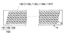
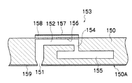
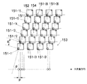
図14(a) はヘッド150の構造例を示す平面透視図であり、図14(b) はその一部の拡大図である。また、図14(c) はヘッド150の他の構造例を示す平面透視図、図15は1つの液滴吐出素子(1つのノズル151に対応したインク室ユニット)の立体的構成を示す断面図(図14(a) 中の15−15線に沿う断面図)である。
FIG. 14A is a plan perspective view showing an example of the structure of the
記録紙116上に印字されるドットピッチを高密度化するためには、ヘッド150におけるノズルピッチを高密度化する必要がある。本例のヘッド150は、図14(a),(b) に示したように、インク吐出口であるノズル151と、各ノズル151に対応する圧力室152等からなる複数のインク室ユニット(液滴吐出素子)153を千鳥でマトリクス状に(2次元的に)配置させた構造を有し、これにより、ヘッド長手方向(紙送り方向と直交する方向)に沿って並ぶように投影される実質的なノズル間隔(投影ノズルピッチ)の高密度化を達成している。
In order to increase the dot pitch printed on the
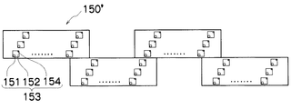
記録紙116の送り方向と略直交する方向に記録紙116の全幅に対応する長さにわたり1列以上のノズル列を構成する形態は本例に限定されない。例えば、図14(a) の構成に代えて、図14(c) に示すように、複数のノズル151が2次元に配列された短尺のヘッドモジュール150’を千鳥状に配列して繋ぎ合わせることで記録紙116の全幅に対応する長さのノズル列を有するラインヘッドを構成してもよい。
The configuration in which one or more nozzle rows are formed over a length corresponding to the entire width of the
各ノズル151に対応して設けられている圧力室152は、その平面形状が概略正方形となっており(図14(a),(b) 参照)、対角線上の両隅部の一方にノズル151への流出口が設けられ、他方に供給インクの流入口(供給口)154が設けられている。なお、圧力室152の形状は、本例に限定されず、平面形状が四角形(菱形、長方形など)、五角形、六角形その他の多角形、円形、楕円形など、多様な形態があり得る。
The
図15に示したように、各圧力室152は供給口154を介して共通流路155と連通されている。共通流路155はインク供給源たるインクタンク(不図示)と連通しており、インクタンクから供給されるインクは共通流路155を介して各圧力室152に分配供給される。
As shown in FIG. 15, each
圧力室152の一部の面(図15において天面)を構成している加圧板(共通電極と兼用される振動板)156には個別電極157を備えたアクチュエータ158が接合されている。個別電極157と共通電極間に駆動電圧を印加することによってアクチュエータ158が変形して圧力室152の容積が変化し、これに伴う圧力変化によりノズル151からインクが吐出される。なお、アクチュエータ158には、チタン酸ジルコン酸鉛やチタン酸バリウムなどの圧電体を用いた圧電素子が好適に用いられる。インク吐出後、アクチュエータ158の変位が元に戻る際に、共通流路155から供給口154を通って新しいインクが圧力室152に再充填される。
An
また、吐出安定性並びに吐出面(ノズル面150A)のクリーニング性を向上させる等の観点から、ヘッド150のノズル面150Aには撥液層159が設けられている。ノズル面150Aに撥液性を付与する方法(撥液処理方法)は、特に限定されず、例えば、フッ素系の撥液材を塗布する方法や、フッ素系高分子粒子(PTFE)等の撥液材を真空中で蒸着し表面に薄層を形成する方法等がある。
In addition, a
入力画像から生成さる打滴配置データに応じて各ノズル151に対応したアクチュエータ158の駆動を制御することにより、ノズル151からインク滴を吐出させることができる。図12で説明したように、記録媒体たる記録紙116を一定の速度で副走査方向に搬送しながら、その搬送速度に合わせて各ノズル151のインク吐出タイミングを制御することによって、記録紙116上に所望の画像を記録することができる。
By controlling the driving of the
上述した構造を有するインク室ユニット153を図16に示す如く主走査方向に沿う行方向及び主走査方向に対して直交しない一定の角度θを有する斜めの列方向とに沿って一定の配列パターンで格子状に多数配列させることにより、本例の高密度ノズルヘッドが実現されている。
As shown in FIG. 16, the
すなわち、主走査方向に対してある角度θの方向に沿ってインク室ユニット153を一定のピッチdで複数配列する構造により、主走査方向に並ぶように投影されたノズルのピッチPはd× cosθとなり、主走査方向については、各ノズル151が一定のピッチPで直線状に配列されたものと等価的に取り扱うことができる。このような構成により、主走査方向に並ぶように投影されるノズル列が1インチ当たり2400個(2400ノズル/インチ)におよぶ高密度のノズル構成を実現することが可能になる。
That is, with a structure in which a plurality of
なお、印字可能幅の全幅に対応した長さのノズル列を有するフルラインヘッドで、ノズルを駆動する時には、(1)全ノズルを同時に駆動する、(2)ノズルを片方から他方に向かって順次駆動する、(3)ノズルをブロックに分割して、ブロックごとに片方から他方に向かって順次駆動する等が行われ、用紙の幅方向(用紙の搬送方向と直交する方向)に1ライン(1列のドットによるライン又は複数列のドットから成るライン)を印字するようなノズルの駆動を主走査と定義する。 When the nozzles are driven by a full line head having a nozzle row having a length corresponding to the entire printable width, (1) all the nozzles are driven simultaneously, (2) the nozzles are sequentially moved from one side to the other. (3) The nozzles are divided into blocks, and the nozzles are sequentially driven from one side to the other for each block, etc., and one line (1 in the width direction of the paper (direction perpendicular to the paper conveyance direction)) Driving a nozzle that prints a line of dots in a row or a line consisting of dots in a plurality of rows is defined as main scanning.
特に、図16に示すようなマトリクス状に配置されたノズル151を駆動する場合は、上記(3)のような主走査が好ましい。すなわち、ノズル151-11 、151-12 、151-13 、151-14 、151-15 、151-16 を1つのブロックとし(他にはノズル151-21 、…、151-26 を1つのブロック、ノズル151-31 、…、151-36 を1つのブロック、…として)、記録紙116の搬送速度に応じてノズル151-11 、151-12 、…、151-16 を順次駆動することで記録紙116の幅方向に1ラインを印字する。
In particular, when driving the
一方、上述したフルラインヘッドと用紙とを相対移動することによって、上述した主走査で形成された1ライン(1列のドットによるライン又は複数列のドットから成るライン)の印字を繰り返し行うことを副走査と定義する。 On the other hand, by relatively moving the above-mentioned full line head and the paper, printing of one line (a line formed by one line of dots or a line composed of a plurality of lines) formed by the above-described main scanning is repeatedly performed. This is defined as sub-scanning.
そして、上述の主走査によって記録される1ライン(或いは帯状領域の長手方向)の示す方向を主走査方向といい、上述の副走査を行う方向を副走査方向という。すなわち、本実施形態では、記録紙116の搬送方向が副走査方向であり、それに直交する方向が主走査方向ということになる。
The direction indicated by one line (or the longitudinal direction of the belt-like region) recorded by the main scanning is referred to as a main scanning direction, and the direction in which the sub scanning is performed is referred to as a sub scanning direction. In other words, in the present embodiment, the conveyance direction of the
本発明の実施に際してノズルの配置構造は図示の例に限定されない。また、本実施形態では、ピエゾ素子(圧電素子)に代表されるアクチュエータ158の変形によってインク滴を飛ばす方式が採用されているが、本発明の実施に際して、インクを吐出させる方式は特に限定されず、ピエゾジェット方式に代えて、ヒータなどの発熱体によってインクを加熱して気泡を発生させ、その圧力でインク滴を飛ばすサーマルジェット方式など、各種方式を適用できる。
In implementing the present invention, the nozzle arrangement structure is not limited to the illustrated example. In this embodiment, a method of ejecting ink droplets by deformation of an
〔制御系の説明〕
図17は、インクジェット記録装置110のシステム構成を示すブロック図である。同図に示したように、インクジェット記録装置110は、通信インターフェース170、システムコントローラ172、ノズル面−媒体間距離情報取得部173、画像メモリ174、ROM175、モータドライバ176、ヒータドライバ178、プリント制御部180、画像バッファメモリ182、ヘッドドライバ184等を備えている。
[Explanation of control system]
FIG. 17 is a block diagram illustrating a system configuration of the
通信インターフェース170は、ホストコンピュータ186から送られてくる画像データを受信するインターフェース部(画像入力手段)である。通信インターフェース170にはUSB(Universal Serial Bus)、IEEE1394、イーサネット(登録商標)、無線ネットワークなどのシリアルインターフェースやセントロニクスなどのパラレルインターフェースを適用することができる。この部分には、通信を高速化するためのバッファメモリ(不図示)を搭載してもよい。
The
ホストコンピュータ186から送出された画像データは通信インターフェース170を介してインクジェット記録装置110に取り込まれ、一旦画像メモリ174に記憶される。画像メモリ174は、通信インターフェース170を介して入力された画像を格納する記憶手段であり、システムコントローラ172を通じてデータの読み書きが行われる。画像メモリ174は、半導体素子からなるメモリに限らず、ハードディスクなど磁気媒体を用いてもよい。
Image data sent from the
システムコントローラ172は、中央演算処理装置(CPU)及びその周辺回路等から構成され、所定のプログラムに従ってインクジェット記録装置110の全体を制御する制御装置として機能するとともに、各種演算を行う演算装置として機能する。すなわち、システムコントローラ172は、通信インターフェース170、画像メモリ174、モータドライバ176、ヒータドライバ178等の各部を制御し、ホストコンピュータ186との間の通信制御、画像メモリ174及びROM175の読み書き制御等を行うとともに、搬送系のモータ188やヒータ189を制御する制御信号を生成する。
The
また、システムコントローラ172は、ノズル面−媒体間距離情報取得部173から得た距離情報と印字検出部124から読み込んだテストパターンの読取データから着弾位置誤差のデータを生成する演算処理を行う着弾誤差測定演算部172Aと、測定された着弾位置誤差の情報から濃度補正係数を算出する濃度補正係数算出部172Bとを含んで構成される。なお、着弾誤差測定演算部172A及び濃度補正係数算出部172Bの処理機能はASICやソフトウエア又は適宜の組み合わせによって実現可能である。
Further, the
濃度補正係数算出部172Bにおいて求められた濃度補正係数のデータは、濃度補正係数記憶部190に記憶される。
The density correction coefficient data obtained by the density correction
ノズル面−媒体間距離情報取得部173は、図12で説明した距離測定部123、或いは、ユーザーが記録媒体(記録紙116)の厚み情報を入力するためのユーザーインターフェースなどの態様を含む。
The nozzle surface-medium distance
ROM175には、システムコントローラ172のCPUが実行するプログラム及び制御に必要な各種データ(例えば、着弾位置誤差測定用のテストパターンのデータ、着弾位置ずれ量の演算に必要な演算式、ルックアップテーブル、Ya ,Xai の値)などが格納されている。ROM175は、書換不能な記憶手段であってもよいが、Xaiの情報を更新する場合は、EEPROMのような書換可能な記憶手段を用いることが好ましい。また、このROM175の記憶領域を活用することで、ROM175を濃度補正係数記憶部190として兼用する構成も可能である。
The
画像メモリ174は、画像データの一時記憶領域として利用されるとともに、プログラムの展開領域及びCPUの演算作業領域としても利用される。
The
モータドライバ176は、システムコントローラ172からの指示に従って搬送系のモータ188を駆動するドライバ(駆動回路)である。ヒータドライバ178は、システムコントローラ172からの指示に従って後乾燥部142等のヒータ189を駆動するドライバである。
The
プリント制御部180は、システムコントローラ172の制御に従い、画像メモリ174内の画像データ(多値の入力画像のデータ) から打滴制御用の信号を生成するための各種加工、補正などの処理を行う信号処理手段として機能するとともに、生成したインク吐出データをヘッドドライバ184に供給してヘッド150の吐出駆動を制御する吐出制御手段として機能する。
In accordance with the control of the
すなわち、プリント制御部180は、濃度データ生成部180Aと、補正処理部180Bと、インク吐出データ生成部180Cと、駆動波形生成部180Dとを含んで構成される。これら各機能ブロック(180A〜D)は、ASICやソフトウエア又は適宜の組み合わせによって実現可能である。
That is, the
濃度データ生成部180Aは、入力画像のデータからインク色別の初期の濃度データを生成する信号処理手段であり、図9のステップS22で説明した濃度変換処理(UCR処理や色変換を含む)及び必要な場合には画素数変換処理を行う。
The density
図17の補正処理部180Bは、濃度補正係数記憶部190に格納されている濃度補正係数を用いて濃度補正の演算を行う処理手段であり、図9のステップS32で説明したムラ補正処理を行う。
The
図17のインク吐出データ生成部180Cは、補正処理部180Bで生成された補正後の濃度データから2値(又は多値)の打滴配置データ(ドットデータ)に変換するハーフトーニング処理(中間階調処理)手段を含む信号処理手段であり、図9のステップS42で説明した2値(多値)化処理を行う。インク吐出データ生成部180Cにて生成されたインク吐出データはヘッドドライバ184に与えられ、ヘッド150のインク吐出動作が制御される。
The ink ejection
駆動波形生成部180Dは、ヘッド150の各ノズル151に対応したアクチュエータ158(図12参照)を駆動するための駆動信号波形を生成する手段であり、該駆動波形生成部180Dにて生成された信号(駆動波形)は、ヘッドドライバ184に供給される。なお、駆動信号生成部180Dから出力される信号は、デジタル波形データであってもよいし、アナログ電圧信号であってもよい。
The drive waveform generation unit 180D is a unit that generates a drive signal waveform for driving the actuator 158 (see FIG. 12) corresponding to each
プリント制御部180には画像バッファメモリ182が備えられており、プリント制御部180における画像データ処理時に画像データやパラメータなどのデータが画像バッファメモリ182に一時的に格納される。なお、図17において画像バッファメモリ182はプリント制御部180に付随する態様で示されているが、画像メモリ174と兼用することも可能である。また、プリント制御部180とシステムコントローラ172とを統合して1つのプロセッサで構成する態様も可能である。
The
画像入力から印字出力までの処理の流れを概説すると、印刷すべき画像のデータは、通信インターフェース170を介して外部から入力され、画像メモリ174に蓄えられる。この段階では、例えば、RGBの多値の画像データが画像メモリ174に記憶される。
An outline of the flow of processing from image input to print output is as follows. Image data to be printed is input from the outside via the
インクジェット記録装置110では、インク(色材) による微細なドットの打滴密度やドットサイズを変えることによって、人の目に疑似的な連続階調の画像を形成するため、入力されたデジタル画像の階調(画像の濃淡)をできるだけ忠実に再現するようなドットパターンに変換する必要がある。そのため、画像メモリ174に蓄えられた元画像(RGB)のデータは、システムコントローラ172を介してプリント制御部180に送られ、該プリント制御部180の濃度データ生成部180A、補正処理部180B、インク吐出データ生成部180Cを経てインク色ごとのドットデータに変換される。
In the ink
すなわち、プリント制御部180は、入力されたRGB画像データをK,C,M,Yの4色のドットデータに変換する処理を行う。こうして、プリント制御部180で生成されたドットデータは、画像バッファメモリ182に蓄えられる。この色別ドットデータは、ヘッド150のノズルからインクを吐出するためのCMYK打滴配置データに変換され、印字されるインク吐出データが確定する。
That is, the
ヘッドドライバ184は、プリント制御部180から与えられるインク吐出データ及び駆動波形の信号に基づき、印字内容に応じてヘッド150の各ノズル151に対応するアクチュエータ158を駆動するための駆動信号を出力する。ヘッドドライバ184にはヘッドの駆動条件を一定に保つためのフィードバック制御系を含んでいてもよい。
The
こうして、ヘッドドライバ184から出力された駆動信号がヘッド150に加えられることによって、該当するノズル151からインクが吐出される。記録紙116の搬送速度に同期してヘッド150からのインク吐出を制御することにより、記録紙116上に画像が形成される。
In this way, when the drive signal output from the
上記のように、プリント制御部180における所要の信号処理を経て生成されたインク吐出データ及び駆動信号波形に基づき、ヘッドドライバ184を介して各ノズルからのインク液滴の吐出量や吐出タイミングの制御が行われる。これにより、所望のドットサイズやドット配置が実現される。
As described above, based on the ink discharge data and the drive signal waveform generated through the required signal processing in the
印字検出部124は、図12で説明したように、イメージセンサを含むブロックであり、記録紙116に印字された画像を読み取り、所要の信号処理などを行って印字状況(吐出の有無、打滴の着弾位置ばらつき、光学濃度など)を検出し、その検出結果をプリント制御部180及びシステムコントローラ172に提供する。
As described with reference to FIG. 12, the
プリント制御部180は、必要に応じて印字検出部124から得られる情報に基づいてヘッド150に対する各種補正を行うとともに、必要に応じて予備吐出や吸引、ワイピング等のクリーニング動作(ノズル回復動作)を実施する制御を行う。
The
本例の場合、ノズル面−媒体間距離情報取得部173が「距離特定手段」及び「第2の距離情報取得手段」並びに「測定手段」に相当し、着弾誤差測定演算部172Aが「着弾位置誤差演算手段」並びに「第2の着弾位置誤差演算手段」に相当する。また、ROM175が「記憶手段」に相当し、該ROM175に記憶されたYa,Xaiの情報を利用する構成が「第1の着弾位置誤差情報取得手段」に相当する。更に、濃度データ生成部180A,補正処理部180B,インク吐出データ生成部180Cを含むプリント制御部180の構成が「打滴配置決定手段」及び「吐出制御手段」に相当し、ROM175内のテストパターンデータに基づいてテストパターンの印字を実行するシステムコントローラ172及びプリント制御部180の組合せが「テストパターン記録制御手段」に相当する。
In the case of this example, the nozzle surface-medium distance
また、濃度補正係数算出部172Bが「補正範囲設定手段」及び「補正係数決定手段」に相当し、補正処理部180Bが「補正処理手段」に相当している。
The density correction
上記構成のインクジェット記録装置110によれば、ハーフトーニング処理(中間階調処理)の前段階で、ノズル面−媒体面間の距離に応じた着弾位置誤差を考慮して画像データの補正が行われるため、着弾位置誤差によるスジムラを精度よく補正できる。また、本例の補正機能は、メカ的な距離制御機構や飛翔偏向のための駆動素子の追加が不要なため、低コストで実現可能である。
According to the ink
〔変形例〕
図17で説明した着弾誤差測定演算部172A、濃度補正係数算出部172B、濃度データ生成部180A、補正処理部180Bが担う処理機能の全て又は一部をホストコンピュータ186側に搭載する態様も可能である。
[Modification]
A mode in which all or part of the processing functions of the landing error
更に、本発明の適用はラインヘッド方式のプリンタに限定されず、シャトルスキャン方式のプリンタにおけるスジムラに対しても有効な補正効果を得ることができる。 Further, the application of the present invention is not limited to a line head type printer, and an effective correction effect can be obtained even for stripe unevenness in a shuttle scan type printer.
また、本発明の実施に際して、着弾位置ずれ量Xbiの情報を利用した補正処理の方法は、図3乃至図11で詳述した例に限定されず、他の補正方法を適用することも可能である。 In the implementation of the present invention, the correction processing method using the information on the landing position deviation amount Xbi is not limited to the example described in detail with reference to FIGS. 3 to 11, and other correction methods may be applied. is there.
1…記録ヘッド、2…ノズル面、3…ノズル、10…ラインヘッド、110…インクジェット記録装置、112…印字部、112K,112C,112M,112Y…ヘッド、114…インク貯蔵/装填部、116…記録紙(記録媒体)、122…ベルト搬送部(搬送手段)、123…距離測定部、124…印字検出部、150…ヘッド、151…ノズル、152…圧力室、153…インク室ユニット、158…アクチュエータ、172…システムコントローラ、172A…着弾誤差測定演算部、172B…濃度補正係数算出部、173…ノズル面−媒体間距離情報取得部、175…ROM、180…プリント制御部、180A…濃度データ生成部、180B…補正処理部、180C…インク吐出データ生成部、180D…駆動波形生成部、184…ヘッドドライバ
DESCRIPTION OF
Claims (9)
前記距離に基づいて前記記録面上での前記液滴吐出口から吐出される液滴の着弾位置ずれ量を特定し、
前記特定した着弾位置ずれ量に応じて画像データを補正して中間階調処理を行うことにより打滴配置データを生成することを特徴とする画像処理方法。 Grasping the distance between the discharge surface of the liquid discharge head formed with a plurality of droplet discharge ports and the recording surface on which the liquid discharged from the droplet discharge ports lands,
Specify the amount of landing position deviation of the droplets discharged from the droplet discharge port on the recording surface based on the distance,
An image processing method comprising generating droplet ejection arrangement data by correcting image data in accordance with the specified landing position deviation amount and performing intermediate gradation processing.
前記吐出面から前記第1の距離とは異なる第2の距離にある第2の記録面について、前記第2の距離の情報を取得する第2の距離情報取得工程と、
前記第1及び第2の距離と前記第1の記録面上で測定された前記着弾位置ずれ量に基づいて、前記第2の記録面上における着弾位置ずれ量を求める第2の着弾位置誤差演算工程と、
前記第2の着弾位置ずれ量演算工程で求めた前記第2の記録面上における着弾位置ずれ量に応じて画像データを補正して中間階調処理を行うことにより打滴配置データを生成する打滴配置決定工程と、
を含むことを特徴とする画像処理方法。 The amount of landing position deviation of the droplets ejected from the droplet ejection port measured on the first recording surface at the first distance from the ejection surface of the liquid ejection head in which a plurality of droplet ejection ports are formed. A first landing position error information acquisition step of acquiring information;
A second distance information acquisition step of acquiring information of the second distance for a second recording surface at a second distance different from the first distance from the ejection surface;
A second landing position error calculation for obtaining a landing position deviation amount on the second recording surface based on the first and second distances and the landing position deviation amount measured on the first recording surface. Process,
The shot placement arrangement data is generated by correcting the image data according to the landing position deviation amount on the second recording surface obtained in the second landing position deviation amount calculation step and performing intermediate gradation processing. Drop placement determination process;
An image processing method comprising:
前記距離に基づいて前記記録面上での前記液滴吐出口から吐出される液滴の着弾位置ずれ量を求める着弾位置誤差演算手段と、
前記着弾位置誤差演算手段によって求めた着弾位置ずれ量に応じて画像データを補正して中間階調処理を行うことにより打滴配置データを生成する打滴配置決定手段と、
を備えたことを特徴とする画像処理装置。 Distance specifying means for specifying the distance between the discharge surface of the liquid discharge head formed with a plurality of droplet discharge ports and the recording surface on which the liquid discharged from the droplet discharge ports lands;
Landing position error calculation means for obtaining the landing position deviation amount of the droplets discharged from the droplet discharge port on the recording surface based on the distance;
Droplet placement determining means for generating droplet placement data by correcting the image data according to the landing position deviation amount obtained by the landing position error calculating means and performing halftone processing;
An image processing apparatus comprising:
前記吐出面から前記第1の距離とは異なる第2の距離にある第2の記録面について、前記第2の距離の情報を取得する第2の距離情報取得手段と、
前記第1及び第2の距離と前記第1の記録面上で測定された前記着弾位置ずれ量に基づいて、前記第2の記録面上における着弾位置ずれ量を求める第2の着弾位置誤差演算手段と、
前記第2の着弾位置誤差演算手段で求めた前記第2の記録面上における着弾位置ずれ量に応じて画像データを補正して中間階調処理を行うことにより打滴配置データを生成する打滴配置決定手段と、
を備えたことを特徴とする画像処理装置。 The amount of landing position deviation of the droplets ejected from the droplet ejection port measured on the first recording surface at the first distance from the ejection surface of the liquid ejection head in which a plurality of droplet ejection ports are formed. First landing position error information acquisition means for acquiring information;
Second distance information acquisition means for acquiring information of the second distance for a second recording surface at a second distance different from the first distance from the ejection surface;
A second landing position error calculation for obtaining a landing position deviation amount on the second recording surface based on the first and second distances and the landing position deviation amount measured on the first recording surface. Means,
Droplet generation for generating droplet placement arrangement data by correcting the image data according to the landing position deviation amount on the second recording surface obtained by the second landing position error calculating means and performing intermediate gradation processing An arrangement determining means;
An image processing apparatus comprising:
前記複数の液滴吐出口のうち、出力濃度の補正に用いるN個(ただし、Nは2以上の整数)の液滴吐出口を設定する補正範囲設定手段と、
前記液滴吐出口から吐出される液滴の着弾位置誤差に起因する濃度ムラの空間周波数特性を表すパワースペクトルの周波数原点(f=0)における微分係数が略0となる条件を含む補正条件に基づいて前記N個の液滴吐出口から吐出される液滴の濃度補正係数を決定する補正係数決定手段と、
前記補正係数決定手段で決定された濃度補正係数を用いて出力濃度を補正する演算を行う補正処理手段と、
を含むことを特徴とする請求項4又は5記載の画像処理装置。 The droplet placement arrangement determining means includes
A correction range setting means for setting N (N is an integer of 2 or more) droplet discharge ports to be used for output density correction among the plurality of droplet discharge ports;
Correction conditions including a condition that the differential coefficient at the frequency origin (f = 0) of the power spectrum representing the spatial frequency characteristic of density unevenness caused by the landing position error of the droplet discharged from the droplet discharge port is substantially zero. Correction coefficient determining means for determining a density correction coefficient of droplets ejected from the N droplet ejection ports based on the above,
Correction processing means for performing an operation of correcting the output density using the density correction coefficient determined by the correction coefficient determination means;
The image processing apparatus according to claim 4, further comprising:
前記液体吐出ヘッド及び被記録媒体のうち少なくとも一方を搬送して前記液体吐出ヘッドと前記被記録媒体を相対移動させる搬送手段と、
前記液体吐出ヘッドの吐出面から第1の距離にある第1の記録面上で測定された前記液滴吐出口から吐出される液滴の着弾位置ずれ量と前記第1の距離の情報を記憶しておく記憶手段と、
前記吐出面から前記第1の距離とは異なる第2の距離にある第2の記録面について、前記第2の距離の情報を取得する第2の距離情報取得手段と、
前記記憶手段に記憶されている前記第1の距離及び前記第1の記録面上における前記着弾位置ずれ量、並びに前記第2の距離情報取得手段で取得された前記第2の距離に基づいて、前記第2の記録面上における着弾位置ずれ量を求める第2の着弾位置誤差演算手段と、
前記第2の着弾位置誤差演算手段で求めた前記第2の記録面上における着弾位置ずれ量に応じて画像データを補正して中間階調処理を行うことで打滴配置データを生成する打滴配置決定手段と、
前記打滴配置決定手段によって生成された打滴配置データに基づいて前記液滴吐出口からの吐出動作を制御する吐出制御手段と、
を備えたことを特徴とする画像記録装置。 A liquid discharge head in which a plurality of droplet discharge ports are formed;
Transport means for transporting at least one of the liquid ejection head and the recording medium to relatively move the liquid ejection head and the recording medium;
Information on the amount of landing position deviation of the droplet ejected from the droplet ejection port measured on the first recording surface at a first distance from the ejection surface of the liquid ejection head and information on the first distance are stored. Storage means to keep,
Second distance information acquisition means for acquiring information of the second distance for a second recording surface at a second distance different from the first distance from the ejection surface;
Based on the first distance stored in the storage means and the amount of landing position deviation on the first recording surface, and the second distance acquired by the second distance information acquisition means, Second landing position error calculating means for obtaining a landing position deviation amount on the second recording surface;
Droplet generation for generating droplet placement arrangement data by correcting the image data in accordance with the amount of landing position deviation on the second recording surface obtained by the second landing position error calculating means and performing halftone processing An arrangement determining means;
Discharge control means for controlling the discharge operation from the droplet discharge port based on the droplet placement data generated by the droplet placement determination means;
An image recording apparatus comprising:
前記第1の記録面上に記録された前記テストパターンから着弾位置ずれ量を測定する測定手段と、
を備え、前記測定手段で測定した着弾位置ずれ量の情報が前記記憶手段に記憶されることを特徴とする請求項7記載の画像記録装置。 Test pattern recording control means for controlling ejection driving of the liquid ejection head so as to record a predetermined test pattern on the first recording surface;
Measuring means for measuring a landing position deviation amount from the test pattern recorded on the first recording surface;
The image recording apparatus according to claim 7, wherein information on a landing position deviation measured by the measuring unit is stored in the storage unit.
9. The image recording apparatus according to claim 7, wherein the first recording surface is a surface of a conveyance belt for conveying the recording medium.
Priority Applications (2)
| Application Number | Priority Date | Filing Date | Title |
|---|---|---|---|
| JP2005204467A JP2007021807A (en) | 2005-07-13 | 2005-07-13 | Method and device for processing image, and image recorder |
| US11/484,571 US7422306B2 (en) | 2005-07-13 | 2006-07-12 | Image processing method, image processing apparatus, and image recording apparatus |
Applications Claiming Priority (1)
| Application Number | Priority Date | Filing Date | Title |
|---|---|---|---|
| JP2005204467A JP2007021807A (en) | 2005-07-13 | 2005-07-13 | Method and device for processing image, and image recorder |
Publications (1)
| Publication Number | Publication Date |
|---|---|
| JP2007021807A true JP2007021807A (en) | 2007-02-01 |
Family
ID=37661275
Family Applications (1)
| Application Number | Title | Priority Date | Filing Date |
|---|---|---|---|
| JP2005204467A Pending JP2007021807A (en) | 2005-07-13 | 2005-07-13 | Method and device for processing image, and image recorder |
Country Status (2)
| Country | Link |
|---|---|
| US (1) | US7422306B2 (en) |
| JP (1) | JP2007021807A (en) |
Cited By (4)
| Publication number | Priority date | Publication date | Assignee | Title |
|---|---|---|---|---|
| JP2009172946A (en) * | 2008-01-28 | 2009-08-06 | Ricoh Co Ltd | Image forming apparatus |
| JP2020121504A (en) * | 2019-01-31 | 2020-08-13 | セイコーエプソン株式会社 | Working gap determination method, and recording device |
| JP2020142407A (en) * | 2019-03-05 | 2020-09-10 | コニカミノルタ株式会社 | Inkjet recording device and method for setting compensation for discharge failure nozzle |
| US11878509B2 (en) | 2021-01-28 | 2024-01-23 | Seiko Epson Corporation | Liquid ejecting apparatus, inspection method, and storage medium |
Families Citing this family (6)
| Publication number | Priority date | Publication date | Assignee | Title |
|---|---|---|---|---|
| US20080259126A1 (en) * | 2007-04-23 | 2008-10-23 | Hewlett-Packard Development Company Lp | Printing control |
| DE102008052421A1 (en) * | 2008-10-21 | 2010-04-22 | Giesecke & Devrient Gmbh | Apparatus and method for printing a banderole strip |
| EP3417813B1 (en) | 2011-08-05 | 2020-05-13 | Cardiovalve Ltd | Percutaneous mitral valve replacement |
| WO2013021374A2 (en) | 2011-08-05 | 2013-02-14 | Mitraltech Ltd. | Techniques for percutaneous mitral valve replacement and sealing |
| JP6769732B2 (en) * | 2016-04-22 | 2020-10-14 | 東芝テック株式会社 | Correction data setting device and inkjet printer |
| JP6613214B2 (en) * | 2016-07-29 | 2019-11-27 | 富士フイルム株式会社 | Printed matter inspection apparatus, printed matter inspection method and program |
Family Cites Families (5)
| Publication number | Priority date | Publication date | Assignee | Title |
|---|---|---|---|---|
| JPH0286457A (en) | 1988-09-22 | 1990-03-27 | Canon Inc | liquid jet recording device |
| JP2001130112A (en) * | 1999-11-04 | 2001-05-15 | Seiko Epson Corp | Printing device that adjusts the formation position deviation between dots |
| US6764156B2 (en) * | 2000-12-12 | 2004-07-20 | Xerox Corporation | Head signature correction in a high resolution printer |
| JP4528481B2 (en) * | 2002-04-05 | 2010-08-18 | セイコーエプソン株式会社 | Printing that changes the dot recording rate according to the ink droplet size error |
| JP3695537B2 (en) | 2002-10-18 | 2005-09-14 | ソニー株式会社 | Liquid ejection apparatus and liquid ejection method |
-
2005
- 2005-07-13 JP JP2005204467A patent/JP2007021807A/en active Pending
-
2006
- 2006-07-12 US US11/484,571 patent/US7422306B2/en not_active Expired - Fee Related
Cited By (6)
| Publication number | Priority date | Publication date | Assignee | Title |
|---|---|---|---|---|
| JP2009172946A (en) * | 2008-01-28 | 2009-08-06 | Ricoh Co Ltd | Image forming apparatus |
| JP2020121504A (en) * | 2019-01-31 | 2020-08-13 | セイコーエプソン株式会社 | Working gap determination method, and recording device |
| JP7172665B2 (en) | 2019-01-31 | 2022-11-16 | セイコーエプソン株式会社 | Working gap determination method and recording device |
| JP2020142407A (en) * | 2019-03-05 | 2020-09-10 | コニカミノルタ株式会社 | Inkjet recording device and method for setting compensation for discharge failure nozzle |
| JP7293732B2 (en) | 2019-03-05 | 2023-06-20 | コニカミノルタ株式会社 | Inkjet recording apparatus and complementary setting method for defective ejection nozzles |
| US11878509B2 (en) | 2021-01-28 | 2024-01-23 | Seiko Epson Corporation | Liquid ejecting apparatus, inspection method, and storage medium |
Also Published As
| Publication number | Publication date |
|---|---|
| US20070013731A1 (en) | 2007-01-18 |
| US7422306B2 (en) | 2008-09-09 |
Similar Documents
| Publication | Publication Date | Title |
|---|---|---|
| JP5131931B2 (en) | Image recording apparatus, image processing apparatus, image processing method, and program | |
| JP5101008B2 (en) | Image recording apparatus and method | |
| US8292401B2 (en) | Image recording apparatus and image recording method | |
| JP4823599B2 (en) | Method for adjusting droplet ejection position error, droplet ejection control method, and image forming apparatus | |
| US20110227988A1 (en) | Fine pattern position detection method and apparatus, defective nozzle detection method and apparatus, and liquid ejection method and apparatus | |
| JP4810618B2 (en) | Image processing method and image recording apparatus | |
| JP2010083007A (en) | Apparatus, method and program for processing image, and image recording apparatus | |
| JP5398300B2 (en) | Image recording apparatus, image processing apparatus, image processing method, and program | |
| JP5094504B2 (en) | Image forming apparatus | |
| JP4721118B2 (en) | Image processing apparatus and method, and image forming apparatus and method | |
| JP2008092191A (en) | Image processing method and apparatus, and image forming method and apparatus | |
| JP2012066516A (en) | Image recording apparatus, and device, method, and program for calculating correction value | |
| US7484824B2 (en) | Image recording apparatus and method, and method of specifying density correction coefficients | |
| US8243291B2 (en) | Image forming apparatus with correction device for defect correction | |
| JP4868937B2 (en) | Image recording apparatus and method, and density correction coefficient determination method | |
| JP5117242B2 (en) | Image recording apparatus and method, and image processing program | |
| JP2007021807A (en) | Method and device for processing image, and image recorder | |
| JP2009078390A (en) | Image recording apparatus and method, density correction coefficient determination method and program | |
| JP2010082989A (en) | Apparatus, method and program for processing image, and image recording apparatus | |
| JP2007237398A (en) | Image recording system and method | |
| JP2009226800A (en) | Image processing method and image forming apparatus | |
| JP4596174B2 (en) | Image processing method and image recording apparatus | |
| JP5469796B2 (en) | Image forming apparatus | |
| JP2012066457A (en) | Image forming apparatus, correction value calculator, test chart for density measurement, and correction value calculation method | |
| JP2009241271A (en) | Image recorder, method for recording image and image processing program |
Legal Events
| Date | Code | Title | Description |
|---|---|---|---|
| A711 | Notification of change in applicant |
Free format text: JAPANESE INTERMEDIATE CODE: A712 Effective date: 20070116 |