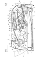
JP2007017488A - Image forming apparatus - Google Patents

Image forming apparatus Download PDF

Info

Publication number
JP2007017488A
JP2007017488A JP2005195948A JP2005195948A JP2007017488A JP 2007017488 A JP2007017488 A JP 2007017488A JP 2005195948 A JP2005195948 A JP 2005195948A JP 2005195948 A JP2005195948 A JP 2005195948A JP 2007017488 A JP2007017488 A JP 2007017488A
Authority
JP
Japan
Prior art keywords
fixing unit
recording medium
tray member
tray
forming apparatus
Prior art date
Legal status (The legal status is an assumption and is not a legal conclusion. Google has not performed a legal analysis and makes no representation as to the accuracy of the status listed.)
Pending
Application number
JP2005195948A
Other languages
Japanese (ja)
Inventor
Takahiro Ikeno
孝宏 池野
Masatoshi Shiraki
雅敏 白木
Current Assignee (The listed assignees may be inaccurate. Google has not performed a legal analysis and makes no representation or warranty as to the accuracy of the list.)
Brother Industries Ltd
Original Assignee
Brother Industries Ltd
Priority date (The priority date is an assumption and is not a legal conclusion. Google has not performed a legal analysis and makes no representation as to the accuracy of the date listed.)
Filing date
Publication date
Application filed by Brother Industries Ltd filed Critical Brother Industries Ltd
Priority to JP2005195948A priority Critical patent/JP2007017488A/en
Priority to DE602005014911T priority patent/DE602005014911D1/en
Priority to EP05015036A priority patent/EP1619563B1/en
Priority to AT05015036T priority patent/ATE434204T1/en
Priority to US11/178,675 priority patent/US7437096B2/en
Publication of JP2007017488A publication Critical patent/JP2007017488A/en
Priority to US12/212,392 priority patent/US7555239B2/en
Pending legal-status Critical Current

Links

Images

Landscapes

  • Electrophotography Configuration And Component (AREA)

Abstract

【課題】 定着ユニットの取り替えを容易に行える構成でありながら、より小型化を図ることのできる画像形成装置を提供する。
【解決手段】 定着ユニット170がシート排出トレイ152の下方に配置されている状態において、定着ユニット170の外殻となるユニットカバー173と、シート排出トレイ152に形成される凹部の最下部を構成するトレイ部材154とが一体として構成されるように、ユニットカバー173とシート排出トレイ152とを形成する。定着ユニット170を筐体102から取り出す場合には、トレイ部材154も定着ユニット170と同時に取り出すことができるため、定着ユニット170を取り出す際にシート排出トレイ152が邪魔にならない。よって容易に定着ユニット170の取り替えを行うことができる。
【選択図】図11
PROBLEM TO BE SOLVED: To provide an image forming apparatus which can be further miniaturized while having a configuration capable of easily replacing a fixing unit.
In a state in which a fixing unit 170 is disposed below a sheet discharge tray 152, a unit cover 173 serving as an outer shell of the fixing unit 170 and a lowermost portion of a recess formed in the sheet discharge tray 152 are configured. The unit cover 173 and the sheet discharge tray 152 are formed so that the tray member 154 is configured integrally. When removing the fixing unit 170 from the housing 102, the tray member 154 can also be removed simultaneously with the fixing unit 170, so that the sheet discharge tray 152 does not get in the way when the fixing unit 170 is removed. Therefore, the fixing unit 170 can be easily replaced.
[Selection] Figure 11

Description

本発明は、画像形成装置に関する。   The present invention relates to an image forming apparatus.

レーザプリンタ等の電子写真方式の画像形成装置においては、レーザダイオード等を含む発光部から射出される光ビームにより、一様に帯電された感光体表面を露光して静電潜像を形成し、静電潜像をトナーにより可視化した後、当該可視像を記録用紙等の記録媒体上に転写することにより、記録媒体上に可視像を形成する。   In an electrophotographic image forming apparatus such as a laser printer, an electrostatic latent image is formed by exposing a uniformly charged photoreceptor surface with a light beam emitted from a light emitting unit including a laser diode, After the electrostatic latent image is visualized with toner, the visible image is transferred onto a recording medium such as recording paper, thereby forming a visible image on the recording medium.

しかし、単に転写された後の画像は静電気力や分散力により記録媒体に付着しているにすぎず、そのままでは容易に記録媒体から剥がれてしまうため、加熱等の処理により可視像を記録媒体上に固定させる定着処理を行う必要がある。   However, the image after being simply transferred is only attached to the recording medium by electrostatic force or dispersion force, and can easily be peeled off from the recording medium as it is. It is necessary to perform a fixing process for fixing the top.

熱定着を行う定着装置は一般的に定着ローラとしての加熱ローラ及び加圧ローラを備えており、当該加熱ローラと加圧ローラとの間を記録媒体等の記録媒体が通過する際に、加熱により半融・合体したトナー等の現像材が記録媒体中に浸透して定着される。加熱ローラは、内部にハロゲンランプ等の熱源を備えており、当該ハロゲンランプの故障などは画像形成装置としての機能を喪失させる致命的なものであるため、定着装置は取替え容易な構造としておく必要があり、前記加熱ローラや加圧ローラなどを一体とした定着ユニットとして、故障の際に容易に取替えができるようにしている(例えば特許文献1参照)。
特開平8−305205号公報 特開平7−210023号公報
A fixing device that performs heat fixing generally includes a heating roller and a pressure roller as a fixing roller. When a recording medium such as a recording medium passes between the heating roller and the pressure roller, the fixing device is heated. A semi-fused and united developer such as toner penetrates into the recording medium and is fixed. The heating roller has a heat source such as a halogen lamp inside, and failure of the halogen lamp is fatal to lose its function as an image forming apparatus. As a fixing unit in which the heating roller, the pressure roller, and the like are integrated, they can be easily replaced in the event of a failure (for example, see Patent Document 1).
JP-A-8-305205 Japanese Patent Laid-Open No. 7-210023

一般家庭でプリンタを使用するユーザにとって、例えば本棚等の余り広くないスペースにプリンタを設置することができれば便利であるから、レーザプリンタ等の画像形成装置の小型化の要請は相当に強い。しかしながら、上記したように定着ユニットを取替え容易とするためには、取替えの際に当該定着ユニットが通過可能なスペースを確保する必要があり(例えば特許文献2の図8参照)、これは一定以上の装置の小型化(特に高さを低くすること)を困難にする方向に働く。   For users who use printers in ordinary homes, it is convenient if the printer can be installed in a not-so-large space such as a bookshelf, for example. Therefore, there is a strong demand for downsizing an image forming apparatus such as a laser printer. However, in order to make it easy to replace the fixing unit as described above, it is necessary to secure a space through which the fixing unit can pass during replacement (for example, see FIG. 8 of Patent Document 2), which is above a certain level. This works in the direction that makes it difficult to reduce the size of the device (especially to reduce the height).

本発明は、係る問題点に鑑みてなされたものであって、定着ユニットの取替えを容易に行える構成でありながら、より小型化を図ることのできる画像形成装置、及び定着ユニットを提供することを目的としている。   SUMMARY An advantage of some aspects of the invention is that it provides an image forming apparatus and a fixing unit that can be further reduced in size while being configured to easily replace the fixing unit. It is aimed.

上記問題を解決するために本発明は、表面にトナー画像が形成される像担持体を備えるプロセスカートリッジと、前記像担持体を露光走査する走査ユニットと、像担持体から記録媒体に転写されるトナー画像を定着する定着ローラが回動可能に支持されている定着ユニットとが、上面と前記上面に連なる正面側側面と背面側側面とを有する筐体内に配され、前記筐体は、その上面に筐体内方へ凹んだシート排出トレイが形成されるとともに、定着ローラの回動軸と直交する方向にある正面側側面および背面側側面のうち定着ユニットに近い背面側側面に定着ユニットを取り出すための開口が設けられ、前記定着ユニットは、前記シート排出トレイ下方位置に配され、前記シート排出トレイは、前記定着ユニットと一体に構成されるトレイ部材を備え、前記定着ユニット及び前記トレイ部材は、前記開口から一体に挿抜可能である画像形成装置を提供する。   In order to solve the above problems, the present invention provides a process cartridge including an image carrier on which a toner image is formed on a surface, a scanning unit for exposing and scanning the image carrier, and the image carrier to be transferred to a recording medium. A fixing unit on which a fixing roller for fixing a toner image is rotatably supported is disposed in a casing having an upper surface, a front side surface and a rear side surface connected to the upper surface, and the casing is arranged on the upper surface. A sheet discharge tray recessed inward of the housing is formed, and the fixing unit is taken out from the front side surface and the rear side surface in the direction orthogonal to the rotation axis of the fixing roller to the rear side surface close to the fixing unit. The fixing unit is disposed below the sheet discharge tray, and the sheet discharge tray is a tray member configured integrally with the fixing unit. Wherein the fixing unit and the tray member is also directed to an image forming apparatus can be inserted into and removed together from the opening.

上記画像形成装置において、前記定着ローラは、加熱ローラ及び当該加熱ローラと対向して設けられる加圧ローラを含み、前記定着ユニットは、前記加熱ローラの上部を覆うとともに当該加熱ローラを回動可能に支持するユニットカバーを備え、前記ユニットカバーと前記トレイ部材とは樹脂から一体成形されていることが好ましく、前記樹脂は耐熱性樹脂であることが好ましい。   In the image forming apparatus, the fixing roller includes a heating roller and a pressure roller provided to face the heating roller, and the fixing unit covers the upper portion of the heating roller and allows the heating roller to rotate. It is preferable that a unit cover to be supported is provided, and that the unit cover and the tray member are integrally formed from a resin, and the resin is preferably a heat resistant resin.

また上記画像形成装置において、前記筐体は、前記背面の開口を塞ぐ揺動自在なカバーを備えることが好ましい。   In the image forming apparatus, it is preferable that the housing includes a swingable cover that closes the opening on the back surface.

また上記画像形成装置において、前記筐体内における前記定着ユニットよりも記録媒体搬送方向下流側であって前記背面側側面の開口から露出する位置には、記録媒体搬送路を形成する内側ガイド部材が配されていることが好ましく、前記内側ガイド部材は、前記背面側側面の開口から挿抜自在に配されていることが好ましい。   In the image forming apparatus, an inner guide member that forms a recording medium conveyance path is arranged at a position downstream of the fixing unit in the casing in the recording medium conveyance direction and exposed from the opening on the back side surface. It is preferable that the inner guide member is disposed so as to be freely inserted and removed from the opening on the rear side surface.

また上記画像形成装置において、前記トレイ部材は、前記筐体上面に設けられたトレイ部材設置開口部に挿嵌されて前記シート排出トレイの凹みの一部を形成するとともに、前記内側ガイド部材と一体的に形成されていることが好ましい。   In the image forming apparatus, the tray member is inserted into a tray member installation opening provided on the upper surface of the housing to form a part of a recess of the sheet discharge tray, and is integrated with the inner guide member. Preferably, it is formed.

また上記画像形成装置において、前記トレイ部材は、前記筐体上面に設けられたトレイ部材設置開口部に挿嵌されて前記シート排出トレイの凹みの一部を形成し、その記録媒体搬送方向下流側端部上側の高さが、それよりも記録媒体搬送方向下流側にある前記トレイ部材設置開口部のトレイ部材側端部上側の高さよりも高いことが好ましい。   Further, in the image forming apparatus, the tray member is inserted into a tray member installation opening provided on the upper surface of the housing to form a part of the recess of the sheet discharge tray, and the downstream side in the recording medium conveyance direction It is preferable that the height on the upper side of the end is higher than the height on the upper side of the tray member side end of the tray member installation opening located further downstream in the recording medium conveyance direction.

また上記画像形成装置において、前記シート排出トレイ上には、記録媒体搬送方向と平行な向きに複数のリブが設けられていることが好ましい。   In the image forming apparatus, it is preferable that a plurality of ribs are provided on the sheet discharge tray in a direction parallel to the recording medium conveyance direction.

また上記画像形成装置において、前記画像形成装置は、前記定着ユニットの下部に記録媒体を積層給紙する給紙カセットを備え、当該給紙カセットから給紙された記録媒体は、当該給紙カセット上側で前記プロセスカートリッジ下側に設けられた記録媒体搬送路に沿って搬送されることが好ましい。   In the image forming apparatus, the image forming apparatus includes a sheet feeding cassette that stacks and feeds recording media below the fixing unit, and the recording medium fed from the sheet feeding cassette is located above the sheet feeding cassette. It is preferable that the sheet is conveyed along a recording medium conveyance path provided below the process cartridge.

また上記画像形成装置において、前記給紙カセットは、前記筐体における正面側側面から挿抜されることが好ましい。   In the image forming apparatus, it is preferable that the paper feeding cassette is inserted and removed from a front side surface of the housing.

また上記画像形成装置において、前記筐体には、正面側側面にも開口が設けられており、前記プロセスカートリッジは、前記正面側側面の開口から取り外し自在に設けられることが好ましい。   In the image forming apparatus, it is preferable that the housing has an opening on a front side surface, and the process cartridge is detachably provided from the opening on the front side surface.

また上記問題を解決するために、表面にトナー画像が形成される像担持体を備えるプロセスカートリッジと、前記像担持体を露光走査する走査ユニットと、像担持体から記録媒体に転写されるトナー画像を定着する定着ローラが回動可能に支持されている定着ユニットとが、上面と前記上面に連なる正面側側面と背面側側面とを有する筐体内に配され、前記筐体は、その上面に筐体内方へ凹んだシート排出トレイが形成されるとともに、定着ローラの回動軸と直交する方向にある正面側側面および背面側側面のうち定着ユニットに近い背面側側面に定着ユニットを取り出すための開口が設けられ、前記定着ユニットは、前記シート排出トレイ下方位置に配され、前記シート排出トレイは、トレイ部材を備えた画像形成装置から定着ユニットを取り出す定着ユニット取り出し方法であって、前記定着ユニットと前記トレイ部材とを前記開口より一体に取り出す工程を備えている定着ユニット取り出し方法を提供する。   In order to solve the above problems, a process cartridge including an image carrier on which a toner image is formed, a scanning unit for exposing and scanning the image carrier, and a toner image transferred from the image carrier to a recording medium A fixing unit rotatably supported by a fixing roller is disposed in a housing having an upper surface, a front side surface connected to the upper surface, and a rear side surface, and the housing is disposed on the upper surface. An opening for taking out the fixing unit to the rear side surface close to the fixing unit among the front side surface and the rear side surface in a direction orthogonal to the rotation axis of the fixing roller, while forming a sheet discharge tray recessed toward the inside of the body The fixing unit is disposed at a lower position of the sheet discharge tray, and the sheet discharge tray removes the fixing unit from an image forming apparatus including a tray member. A fixing unit accessing method issuing Ri, providing a said fixing unit and said tray member METHOD extraction fixing unit comprising a step of taking out the integrally from the opening.

請求項1に記載の画像形成装置又は請求項13に記載の定着ユニット取り出し方法によれば、定着ユニットと定着ユニットを取り出す開口との間に位置するトレイ部材が、定着ユニットと一体に構成されているため、定着ユニットを開口より取り出す際には、必ずシート排出トレイも一緒に取り出される。よってトレイ部材が定着ユニットを取り出す際の障害物とはならず、定着ユニットを開口から容易に取り出すことができる。また定着ユニットとトレイ部材とが一体に設けられているため、定着ユニットを取り出した際に、トレイ部材と定着ユニットとがバラバラになることが無く、トレイ部材の離散、紛失を防止することができる。   According to the image forming apparatus according to claim 1 or the fixing unit taking-out method according to claim 13, the tray member positioned between the fixing unit and the opening for taking out the fixing unit is configured integrally with the fixing unit. Therefore, when the fixing unit is taken out from the opening, the sheet discharge tray is always taken out together. Therefore, the tray member does not become an obstacle when the fixing unit is taken out, and the fixing unit can be easily taken out from the opening. Further, since the fixing unit and the tray member are integrally provided, the tray member and the fixing unit do not fall apart when the fixing unit is taken out, and the tray member can be prevented from being separated or lost. .

請求項2に記載の画像形成装置によれば、一体成型されていることによって、別部材を固定する必要が無いので、製造時の工数を低減できると共に、コストも削減することができる。   According to the image forming apparatus of the second aspect, since it is not necessary to fix another member by being integrally molded, it is possible to reduce the man-hours at the time of manufacture and also to reduce the cost.

請求項3に記載の画像形成装置によれば、少なくとも最も加熱される箇所であるユニットカバー及びトレイ部材のみを耐熱性樹脂により構成することにより、高価な部材である耐熱性樹脂の使用量を必要最小限とすることができ、製造コストの低下を図ることができる。   According to the image forming apparatus of claim 3, at least the unit cover and the tray member, which are the most heated portions, are made of the heat resistant resin, so that the amount of the heat resistant resin that is an expensive member is required. It can be minimized, and the manufacturing cost can be reduced.

請求項4に記載の画像形成装置によれば、定着ユニットの取り替えに際して作業箇所を集約でき、より定着ユニットの取り替えが容易になる。   According to the image forming apparatus of the fourth aspect, it is possible to consolidate work places when replacing the fixing unit, and it becomes easier to replace the fixing unit.

請求項5及び請求項6に記載の画像形成装置によれば、内側ガイド部材が設けられていることにより、定着ユニットを通過した記録媒体をシート排出トレイへと導く記録媒体搬送通路を形成することができる。   According to the image forming apparatus of the fifth and sixth aspects, the inner guide member is provided, thereby forming the recording medium conveyance path for guiding the recording medium that has passed through the fixing unit to the sheet discharge tray. Can do.

請求項7に記載の画像形成装置によれば、内側ガイド部材とトレイ部材が一体に構成されているため、トレイ部材を取り出すときに内側ガイド部材も一体に取り出される。よって内側ガイド部材は、定着ユニットを取り出す時の障害とはならない。   According to the image forming apparatus of the seventh aspect, since the inner guide member and the tray member are integrally formed, the inner guide member is also integrally taken out when the tray member is taken out. Therefore, the inner guide member does not become an obstacle when taking out the fixing unit.

請求項8及び請求項9に記載の画像形成装置によれば、シート排出口から排紙される記録媒体の排紙方向先端が、トレイ部材と筐体上面の開口部との境目部分に引っ掛かるような事態の発生を抑制することができ、スムーズな排紙を行うことができる。またリブが設けられていることにより、更にスムーズに排紙を行うことができる。   According to the image forming apparatus of the eighth aspect and the ninth aspect, the leading end in the paper discharge direction of the recording medium discharged from the sheet discharge port is caught on the boundary portion between the tray member and the opening on the upper surface of the housing. The occurrence of a serious situation can be suppressed, and smooth paper discharge can be performed. Further, by providing the rib, the paper can be discharged more smoothly.

請求項10に記載の画像形成装置によれば、記録媒体搬送通路をいわゆるS字型搬送路とすることができ、画像形成装置の構成をコンパクトにすることができる。   According to the image forming apparatus of the tenth aspect, the recording medium conveyance path can be a so-called S-shaped conveyance path, and the configuration of the image forming apparatus can be made compact.

請求項11及び請求項12に記載の画像形成装置によれば、記録媒体の給紙カセットへの供給及びプロセスカートリッジへのトナーの供給等を容易に行うことができる。   According to the image forming apparatus of the eleventh and twelfth aspects, it is possible to easily supply the recording medium to the paper feed cassette and the toner to the process cartridge.

以下、本発明の実施の形態について図面を参照しながら説明する。   Hereinafter, embodiments of the present invention will be described with reference to the drawings.

(第1の実施の形態)
(1)レーザプリンタの全体構成
図1は、画像形成装置の一例としてのレーザプリンタ1の外観を表す斜視図である。同図のレーザプリンタ1は、上面となるトップカバー18、及び四つの側面2a、2b、2c、2d(側面2c及び2dは図1では見えない位置にある。)を有する筐体2を備えており、トップカバー18が筐体2の内方に凹んでシート排出トレイ52が形成されている。筐体2の下部には、記録紙等の記録媒体を複数枚収納可能な給紙カセット6が、筐体2の正面側側面2aから挿抜自在に設けられている。なお正面側側面2aには、記録媒体を個別にセットする手差しトレイ部11が設けられているとともに、開閉可能なフロントカバー16が設けられている。
(First embodiment)
(1) Overall Configuration of Laser Printer FIG. 1 is a perspective view showing the appearance of a laser printer 1 as an example of an image forming apparatus. The laser printer 1 in FIG. 1 includes a housing 2 having a top cover 18 as an upper surface and four side surfaces 2a, 2b, 2c, and 2d (the side surfaces 2c and 2d are in a position that cannot be seen in FIG. 1). The top cover 18 is recessed inward of the housing 2 to form a sheet discharge tray 52. A paper feed cassette 6 capable of storing a plurality of recording media such as recording paper is provided at the lower portion of the housing 2 so as to be freely inserted and removed from the front side surface 2 a of the housing 2. The front side surface 2a is provided with a manual tray portion 11 for individually setting recording media, and a front cover 16 that can be opened and closed.

以下、図2を参照して、レーザプリンタ1の構成をさらに詳細に説明する。図2は、側面2d側から見たレーザプリンタ1の概略側断面図である。なお、定着ユニット70は、分かりやすくするため簡略化して示している。レーザプリンタ1は、上面のトップカバー18、正面側側面2aに設けられるフロントカバー16、及び背面側側面2cに設けられるリアカバー60等が備えられる筐体2内に、記録媒体としての記録紙等(図中記録媒体搬送路が仮想線Pで表されている。)を給紙するための給紙部3や、給紙された記録媒体上に可視像であるトナー画像を形成するプロセスカートリッジ4、記録媒体上に形成されたトナー画像を記録媒体上に定着させる定着ユニット70、定着ユニット70を通過した記録媒体を排紙する排紙部80などを備えている。なお、本明細書では、筐体2の四つの側面2a〜2dの中で、定着ユニット70に備えられる定着ローラ(後述)の回転軸に直交する方向前後の側面のうち、定着ユニット70に近い側の側面(図2の左側側面)を背面側側面2c、逆側を正面側側面2aとする。   Hereinafter, the configuration of the laser printer 1 will be described in more detail with reference to FIG. FIG. 2 is a schematic sectional side view of the laser printer 1 as viewed from the side surface 2d. Note that the fixing unit 70 is shown in a simplified manner for easy understanding. The laser printer 1 includes a recording paper or the like as a recording medium in a housing 2 provided with a top cover 18 on the top surface, a front cover 16 provided on the front side surface 2a, a rear cover 60 provided on the back side surface 2c, and the like ( In the drawing, a recording medium conveyance path is represented by a virtual line P.) A sheet feeding unit 3 for feeding a sheet) and a process cartridge 4 for forming a visible toner image on the fed recording medium. A fixing unit 70 for fixing the toner image formed on the recording medium onto the recording medium, a paper discharge unit 80 for discharging the recording medium that has passed through the fixing unit 70, and the like. In the present specification, of the four side surfaces 2 a to 2 d of the housing 2, of the side surfaces before and after the direction orthogonal to the rotation axis of a fixing roller (described later) provided in the fixing unit 70, it is close to the fixing unit 70. The side surface on the side (the left side surface in FIG. 2) is the back side surface 2c, and the opposite side is the front side surface 2a.

給紙部3は、給紙カセット6と、給紙カセット6内に積層された記録媒体のシート搬送方向先端側(正面側)端部の上方に設けられた給紙ローラ7、8及び給紙パット9とを含む。給紙部3には、給紙カセット6から給紙された記録媒体を反転させてプロセスカートリッジ4の下部へと搬送する記録媒体搬送路である給紙パス10が形成されており、給紙部3には、給紙パス10に臨むレジストローラ対12を備えている。なお、給紙パス10には、給紙カセット6内の記録媒体の他、手差しトレイ部11に手差しにてセットされた記録媒体(記録紙等)も給紙されるが、いずれの場合も一旦レジストローラ対12にて停止した後、プロセスカートリッジ4における画像形成タイミングに合わせてプロセスカートリッジ4の画像形成部へと供給される。   The paper feed unit 3 includes a paper feed cassette 6 and paper feed rollers 7 and 8 provided above the front end (front side) end of the recording medium stacked in the paper feed cassette 6 in the sheet conveying direction. Including pad 9. The paper feed unit 3 is formed with a paper feed path 10 which is a recording medium transport path for inverting the recording medium fed from the paper feed cassette 6 and transporting it to the lower part of the process cartridge 4. 3 includes a registration roller pair 12 facing the paper feed path 10. In addition to the recording medium in the paper feeding cassette 6, a recording medium (recording paper or the like) manually set on the manual feed tray unit 11 is also fed into the paper feeding path 10. After stopping at the registration roller pair 12, the toner is supplied to the image forming unit of the process cartridge 4 in accordance with the image forming timing in the process cartridge 4.

給紙カセット6は、プロセスカートリッジ4及び定着ユニット70の下部に配され、筐体2の正面側側面から挿抜可能に装着されている。この給紙カセット6内には、用紙押圧板13及びばね14が設けられている。用紙押圧板13は、記録媒体を積層状にスタック可能とされ、給紙ローラ7等から遠い方の端部において揺動可能に支持されることによって、近い方の端部が上下方向に移動可能とされている。また、ばね14は、用紙押圧板13における給紙ローラ7等に近い方の端部の裏面を、上方向に付勢するように設けられている。そのため、用紙押圧板13は、記録媒体の積層量が増えるに従って、給紙ローラ7等に対して遠い方の端部を支点として、ばね14の付勢力に抗して下向きに揺動される。   The paper feed cassette 6 is disposed below the process cartridge 4 and the fixing unit 70 and is detachably mounted from the front side surface of the housing 2. A paper pressing plate 13 and a spring 14 are provided in the paper feeding cassette 6. The sheet pressing plate 13 is capable of stacking recording media in a stacked form, and is supported so as to be swingable at the end far from the paper feed roller 7 and the like, so that the near end can move in the vertical direction. It is said that. The spring 14 is provided so as to urge the back surface of the end of the paper pressing plate 13 closer to the paper feed roller 7 and the like upward. Therefore, the sheet pressing plate 13 is swung downward against the urging force of the spring 14 with the end farther from the sheet feed roller 7 and the like as a fulcrum as the amount of recording medium stacked increases.

給紙ローラ8及び給紙パット9は、互いに対向して配設され、給紙パット9の裏側に設けられるばね15によって、給紙パット9が給紙ローラ8に向かって押圧されている。用紙押圧板13上に積層された中で最上位にある記録媒体は、用紙押圧板13の裏側からばね14によって給紙ローラ7に当接して押圧されており、当該最上位の記録媒体が給紙ローラ7により給紙され、給紙ローラ8と給紙パット9とで挟まれた後、給紙ローラ8が回転することにより、給紙ローラ8及び給紙パット9とで1枚毎に分離されながら、給紙パス10に向かって給紙される。   The paper feed roller 8 and the paper feed pad 9 are disposed to face each other, and the paper feed pad 9 is pressed toward the paper feed roller 8 by a spring 15 provided on the back side of the paper feed pad 9. The uppermost recording medium stacked on the paper pressing plate 13 is pressed against the paper feed roller 7 by a spring 14 from the back side of the paper pressing plate 13, and the uppermost recording medium is fed. After being fed by the paper roller 7 and sandwiched between the paper feed roller 8 and the paper feed pad 9, the paper feed roller 8 is rotated and separated by the paper feed roller 8 and the paper feed pad 9 one by one. However, the paper is fed toward the paper feed path 10.

給紙カセット6、あるいは手差しトレイ部11から給紙された記録媒体は、給紙ローラ7等の上方部に配置されたレジストローラ対12に送られる。レジストローラ対12は、給紙された記録媒体をレジスト後に、プロセスカートリッジ4内の画像形成位置(感光体ドラム37と転写ローラ39との接触位置)へと搬送する。なお、筐体2の正面側側面2aにはフロントカバー16が設けられている。フロントカバー16は筐体2に対して開閉自在に設けられており、フロントカバー16が開放状態となった際に現れる開口からプロセスカートリッジ4の挿抜交換が可能な構成となっている。   The recording medium fed from the paper feed cassette 6 or the manual feed tray unit 11 is sent to a pair of registration rollers 12 arranged above the paper feed roller 7 and the like. The registration roller pair 12 conveys the fed recording medium to the image forming position (contact position between the photosensitive drum 37 and the transfer roller 39) in the process cartridge 4 after registration. A front cover 16 is provided on the front side surface 2 a of the housing 2. The front cover 16 is provided so as to be openable and closable with respect to the housing 2. The process cartridge 4 can be inserted and removed through an opening that appears when the front cover 16 is opened.

プロセスカートリッジ4の上部に設けられる走査ユニット26は、不図示のレーザ発光部、高速回転駆動されるポリゴンミラー29、第1走査レンズ(fθレンズ)30、第2走査レンズ(シリンドリカルレンズ)31、折り返しミラー32及び33などを備えており、レーザ発光部から射出される画像情報に基づいて変調された光ビームを、一点鎖線で示すように、ポリゴンミラー29、第1走査レンズ30、折り返しミラー32、第2走査レンズ31、折り返しミラー33の順に通過あるいは反射させて、プロセスカートリッジ4内の感光体ドラム37の表面上を露光走査させている。   A scanning unit 26 provided on the upper part of the process cartridge 4 includes a laser light emitting unit (not shown), a polygon mirror 29 that is driven to rotate at high speed, a first scanning lens (fθ lens) 30, a second scanning lens (cylindrical lens) 31, and a folding back. Mirrors 32 and 33, etc., and a light beam modulated based on image information emitted from the laser light emitting unit, as indicated by a one-dot chain line, a polygon mirror 29, a first scanning lens 30, a folding mirror 32, The surface of the photosensitive drum 37 in the process cartridge 4 is exposed and scanned by passing or reflecting in the order of the second scanning lens 31 and the folding mirror 33.

プロセスカートリッジ4は、ドラムカートリッジ35及び現像カートリッジ36を含んでいる。ドラムカートリッジ35内には、感光体ドラム37、帯電器38及び転写ローラ39などを備えている。プロセスカートリッジ4は、前記したように、フロントカバー16を開放した際の開口から筐体2内部に着脱自在とされている。現像カートリッジ36は、ドラムカートリッジ35に対して着脱自在に装着されており、現像ローラ40、層厚規制ブレード41、供給ローラ42、トナーホッパー43などを備えている。   The process cartridge 4 includes a drum cartridge 35 and a developing cartridge 36. The drum cartridge 35 includes a photosensitive drum 37, a charger 38, a transfer roller 39, and the like. As described above, the process cartridge 4 is detachable inside the housing 2 from the opening when the front cover 16 is opened. The developing cartridge 36 is detachably attached to the drum cartridge 35, and includes a developing roller 40, a layer thickness regulating blade 41, a supply roller 42, a toner hopper 43, and the like.

トナーホッパー43内のトナーは、回転軸44により支持されるアジテータ45の矢印方向への回転により攪拌され、トナーホッパー43の側部に開口されたトナー供給口46から放出される。トナー供給口46の側方位置に前記供給ローラ42が回転可能に配設されており、また、この供給ローラ42に対向して、現像ローラ40が回転可能に配されている。なお、供給ローラ42と現像ローラ40とは、そのそれぞれがある程度圧縮するような状態で互いに当接されている。   The toner in the toner hopper 43 is agitated by the rotation of the agitator 45 supported by the rotating shaft 44 in the direction of the arrow, and is discharged from the toner supply port 46 opened at the side of the toner hopper 43. The supply roller 42 is rotatably disposed at a side position of the toner supply port 46, and the developing roller 40 is rotatably disposed so as to face the supply roller 42. The supply roller 42 and the developing roller 40 are in contact with each other in a state where each of them is compressed to some extent.

現像ローラ40は、金属製のローラ軸に、導電性のゴム材料からなるローラが被覆されており、矢印方向(反時計方向)に回転駆動される。なお、現像ローラ40には、現像バイアスが印加されるように構成されている。また、現像ローラ40の近傍には、層厚規制ブレード41が配されている。この層厚規制ブレード41は、金属の板ばね材からなるブレード本体の先端部に、絶縁性のシリコーンゴムからなる断面半円形状の押圧部を備えており、現像ローラ40の近くにおいて現像カートリッジ36に支持されて、押圧部がブレード本体の弾性力によって現像ローラ40上に圧接されるように構成されている。   The developing roller 40 has a metal roller shaft covered with a roller made of a conductive rubber material, and is driven to rotate in the direction of the arrow (counterclockwise). The developing roller 40 is configured to be applied with a developing bias. A layer thickness regulating blade 41 is disposed in the vicinity of the developing roller 40. This layer thickness regulating blade 41 is provided with a pressing portion having a semicircular cross section made of insulating silicone rubber at the tip of a blade body made of a metal leaf spring material. The pressing portion is configured to be pressed against the developing roller 40 by the elastic force of the blade body.

トナー供給口46から放出されるトナーは、供給ローラ42の回転により、現像ローラ40に供給され、この時、供給ローラ42と現像ローラ40との間で正に摩擦帯電され、さらに、現像ローラ40上に供給されたトナーは、現像ローラ40の回転に伴って、層厚規制ブレード41の押圧部と現像ローラ40との間に進入し、一定厚さの薄層として現像ローラ40上に担持される。   The toner discharged from the toner supply port 46 is supplied to the developing roller 40 by the rotation of the supplying roller 42. At this time, the toner is positively frictionally charged between the supplying roller 42 and the developing roller 40. The toner supplied above enters between the pressing portion of the layer thickness regulating blade 41 and the developing roller 40 as the developing roller 40 rotates, and is carried on the developing roller 40 as a thin layer having a constant thickness. The

感光体ドラム37は、現像ローラ40の側方位置において、その現像ローラ40と対向するような状態で、ドラムカートリッジ35において、矢印方向(時計方向)に回転可能に支持されている。この感光体ドラム37は、ドラム本体が接地され、その表面がポリカーボネートなどから構成される正帯電性の感光層により形成されている。   The photosensitive drum 37 is supported by the drum cartridge 35 so as to be rotatable in the arrow direction (clockwise) in a state facing the developing roller 40 at a side position of the developing roller 40. The photoreceptor drum 37 is formed of a positively chargeable photosensitive layer whose drum body is grounded and whose surface is made of polycarbonate or the like.

帯電器38は、感光体ドラム37の左斜め方向上方に、所定間隔を隔てて対向配置されている。この帯電器38は、タングステンなどの帯電用ワイヤからコロナ放電を発生させる正帯電用のスコロトロン型の帯電器であり、感光体ドラム37の表面を一様に正極性に帯電させるように構成されている。   The charger 38 is disposed to face the photosensitive drum 37 in the diagonally left direction with a predetermined interval. The charger 38 is a scorotron charger for positive charging that generates corona discharge from a charging wire such as tungsten, and is configured to uniformly charge the surface of the photosensitive drum 37 to a positive polarity. Yes.

転写ローラ39は、感光体ドラム37の下方において、感光体ドラム37に対向配置され、ドラムカートリッジ35に矢印方向(反時計方向)に回転可能に支持されている。この転写ローラ39は、金属製のローラ軸に、導電性のゴム材料からなるローラが被覆されており、転写時には、転写バイアスが印加されるように構成されている。   The transfer roller 39 is disposed below the photoconductive drum 37 so as to face the photoconductive drum 37 and is supported by the drum cartridge 35 so as to be rotatable in an arrow direction (counterclockwise). The transfer roller 39 is configured such that a metal roller shaft is covered with a roller made of a conductive rubber material, and a transfer bias is applied during transfer.

感光体ドラム37の表面は、当該感光体ドラム37の回転に伴ない、まず、帯電器38によって一様に正極性に帯電される。次いで、走査ユニット26からのレーザビームにより露光されて静電潜像が形成される。その後、現像ローラ40と対向し、現像ローラ40上に担持されかつ正帯電されているトナーが感光体ドラム37に対向して接触する時に、現像ローラ40に印加される現像バイアスにより、感光体ドラム37の表面上に形成される静電潜像、すなわち、一様に正帯電されている感光体ドラム37の表面のうち、レーザビームによって露光され電位が下がっている露光部分に供給され、選択的に担持されることによってトナー画像が形成される(反転現像)。   As the photosensitive drum 37 rotates, the surface of the photosensitive drum 37 is first uniformly charged to a positive polarity by the charger 38. Next, exposure is performed with a laser beam from the scanning unit 26 to form an electrostatic latent image. After that, when the toner which is opposed to the developing roller 40 and is positively charged and held on the developing roller 40 comes into contact with the photosensitive drum 37, the developing bias applied to the developing roller 40 causes the photosensitive drum The electrostatic latent image formed on the surface of the photoconductor 37, that is, the surface of the photoconductive drum 37 that is uniformly positively charged, is supplied to the exposed portion of the surface exposed to the laser beam and lowered in potential. A toner image is formed by being carried on (reversal development).

その後、感光体ドラム37の表面上に担持されたトナー画像は、記録媒体が感光体ドラム37と転写ローラ39との間を通る間に、転写ローラ39に印加される転写バイアスによって、記録媒体に転写される。   Thereafter, the toner image carried on the surface of the photosensitive drum 37 is transferred to the recording medium by a transfer bias applied to the transfer roller 39 while the recording medium passes between the photosensitive drum 37 and the transfer roller 39. Transcribed.

定着ユニット70は、給紙カセット6の上部、プロセスカートリッジ4の側方であって、プロセスカートリッジ4よりも記録媒体搬送方向下流側に配設される。本実施の形態の定着ユニット70として、後述するの定着ユニットが備えられる。定着ユニット70は、定着ローラとして、内部にヒータを備える加熱ローラ71、加熱ローラ71と対向して設けられ加熱ローラを押圧するように付勢された加圧ローラ72を含んでいる。   The fixing unit 70 is disposed on the upper side of the sheet feeding cassette 6 and on the side of the process cartridge 4 and on the downstream side of the process cartridge 4 in the recording medium conveyance direction. As the fixing unit 70 of the present embodiment, a fixing unit described later is provided. The fixing unit 70 includes, as a fixing roller, a heating roller 71 provided with a heater therein, and a pressure roller 72 provided to face the heating roller 71 and urged so as to press the heating roller.

加熱ローラ71は金属筒状をなし、例えばハロゲンランプからなるヒータを内装しており、そのヒータによって加熱されるように構成されている。また、加圧ローラ72は、この加熱ローラ71を押圧した状態で、加熱ローラ71に従動して回転される。定着ユニット70の構成については後に詳細に説明する。   The heating roller 71 is in the form of a metal cylinder and includes a heater made of, for example, a halogen lamp, and is configured to be heated by the heater. The pressure roller 72 is rotated by being driven by the heating roller 71 in a state where the heating roller 71 is pressed. The configuration of the fixing unit 70 will be described in detail later.

定着ユニット70においては、プロセスカートリッジ4において記録媒体上に転写された可視像であるトナー画像を、当該記録媒体が加熱ローラ71と加圧ローラ72との間を通過する間に熱定着させ、その後、記録媒体を排紙部80に形成される記録媒体搬送路である排紙パス50へと送出するようにしている。   In the fixing unit 70, the toner image, which is a visible image transferred onto the recording medium in the process cartridge 4, is thermally fixed while the recording medium passes between the heating roller 71 and the pressure roller 72. Thereafter, the recording medium is sent to a paper discharge path 50 that is a recording medium conveyance path formed in the paper discharge unit 80.

排紙部80は、排紙パス50を構成する内側ガイド部材51と外側ガイド部材62、記録媒体をトップカバー18に設けられたシート排出トレイ52上へと排出する排出口に設けられる排紙ローラ対のうち、下側の排紙ローラ53、上側の排紙ローラ55、さらにシート排出トレイ52の一部を構成する部分を備えたトレイ部材54を含んでいる。排紙パス50を構成する外側ガイド部材62は、筐体2の背面側側面に設けられるリアカバー60の開閉と連動するように構成されており、ヒンジ61を介して揺動自在に取り付けられたリアカバー60を開放状態とした場合に、それに連動して外側ガイド部材62上部が背面側へと揺動する。このようにして、リアカバー60の開放により、筐体2の背面側側面2cに形成される開口から排紙パス50が臨むように構成されている。なおリアカバー60には定着ユニット70からの熱を放出するための放熱孔60aが穿設されている。これにより、定着ユニット70から発せられる熱が上昇しながら放熱孔60aを通過し、そこから、それよりも上部に設けられたリアカバー60と筐体2との間の隙間を通過して外部に放出されるため、筐体2内部に熱がこもることが抑制される。   The paper discharge unit 80 includes an inner guide member 51 and an outer guide member 62 that constitute the paper discharge path 50, and a paper discharge roller provided at a discharge port for discharging the recording medium onto a sheet discharge tray 52 provided on the top cover 18. The pair includes a lower discharge roller 53, an upper discharge roller 55, and a tray member 54 having a portion constituting a part of the sheet discharge tray 52. The outer guide member 62 constituting the paper discharge path 50 is configured to be interlocked with the opening and closing of the rear cover 60 provided on the back side surface of the housing 2, and the rear cover is swingably attached via the hinge 61. When 60 is opened, the upper part of the outer guide member 62 swings toward the back side in conjunction with it. In this manner, the discharge path 50 is configured to face the opening formed in the rear side surface 2c of the housing 2 when the rear cover 60 is opened. The rear cover 60 is provided with a heat radiating hole 60 a for releasing heat from the fixing unit 70. As a result, the heat generated from the fixing unit 70 rises and passes through the heat radiating hole 60a, and then passes through the gap between the rear cover 60 and the casing 2 provided above the heat radiating hole 60a and is released to the outside. Therefore, it is possible to prevent heat from being trapped inside the housing 2.

シート排出トレイ52は、平面視略矩形板状をなし、背面側端部が筐体2内部へと凹んで凹部が形成されるとともに、背面側端部から正面側へ向けて徐々に上方に傾斜する構成となっている。本実施の形態では、シート排出トレイ52の背面側端部から徐々に上方へと傾斜する途中部分までがトレイ部材54により構成されており、トレイ部材54の正面側(記録媒体搬送方向先端側)先端部の上面が、トップカバー18のトレイ部材54側端部の下面と当接するように構成している。シート排出トレイ52等の構成の詳細については後述する。   The sheet discharge tray 52 has a substantially rectangular plate shape in plan view, and a rear end is recessed into the housing 2 to form a recess, and is gradually inclined upward from the rear end to the front. It is the composition to do. In the present embodiment, the tray member 54 is configured from the rear side end portion of the sheet discharge tray 52 to the middle portion that gradually inclines upward, and the front side of the tray member 54 (front end side in the recording medium conveyance direction). The top surface of the tip portion is configured to abut the bottom surface of the end portion of the top cover 18 on the tray member 54 side. Details of the configuration of the sheet discharge tray 52 and the like will be described later.

定着ユニット70を通過し、排紙パス50へと送られた記録媒体は、内側ガイド部材51及び外側ガイド部材62により用紙進行方向が反転されて、排紙ローラ対へと送られ、当該排紙ローラ対(53及び55)を介して、シート排出トレイ52上に正面側に向かって排紙される。   The recording medium that has passed through the fixing unit 70 and sent to the paper discharge path 50 is sent to a pair of paper discharge rollers after the paper traveling direction is reversed by the inner guide member 51 and the outer guide member 62. The sheet is discharged on the sheet discharge tray 52 toward the front side through the roller pair (53 and 55).

(2)定着ユニット70の詳細構成
次に本実施の形態の定着ユニット70の構成について詳細に説明する。図3は、定着ユニット70の構成について説明するための斜視図である。なお、説明のためユニットカバー73の端部を切断している。本実施の形態の定着ユニット70は、内部にハロゲンランプ71A等の加熱手段(ヒータ)を備える加熱ローラ71と、加熱ローラ71に対向して設けられ、加熱ローラ71の下方から加熱ローラ71表面を押圧する加圧ローラ72とを備えている。
(2) Detailed Configuration of Fixing Unit 70 Next, the configuration of the fixing unit 70 of the present embodiment will be described in detail. FIG. 3 is a perspective view for explaining the configuration of the fixing unit 70. In addition, the edge part of the unit cover 73 is cut | disconnected for description. The fixing unit 70 according to the present embodiment is provided with a heating roller 71 having a heating means (heater) such as a halogen lamp 71 </ b> A inside and the heating roller 71 facing the heating roller 71. And a pressure roller 72 for pressing.

そして、加熱ローラ71の上部がポリエチレンテレフタレート(PET)等の樹脂を成型したユニットカバー73により覆われているとともに、加圧ローラ72側はユニットカバー73に覆われることなく開放された構成となっており、これによって、定着ユニット70の小型化を介して画像形成装置全体の小型化を図る構成となっている。なお、加圧ローラ72は、その一端の支持部74がユニットカバー73に設けられた支持軸73Aと掛合し、ユニットカバー73に対して回動可能に支持された支持部材としての支持レバー75に回動可能に軸支されている。支持レバー75には、加圧ローラ72の回動軸72Aから見て支持部74とは反対側(記録媒体搬送方向先端側)において、一端がユニットカバー73に係止した弾性体としてのバネ76が係止している。   The upper portion of the heating roller 71 is covered with a unit cover 73 formed by molding a resin such as polyethylene terephthalate (PET), and the pressure roller 72 side is opened without being covered by the unit cover 73. As a result, the entire image forming apparatus is reduced in size through the downsizing of the fixing unit 70. The pressure roller 72 has a support portion 74 at one end engaged with a support shaft 73 </ b> A provided on the unit cover 73, and a support lever 75 as a support member supported rotatably with respect to the unit cover 73. It is pivotally supported so that it can rotate. The support lever 75 has a spring 76 as an elastic body with one end locked to the unit cover 73 on the side opposite to the support portion 74 (front end side in the recording medium conveyance direction) when viewed from the rotation shaft 72A of the pressure roller 72. Is locked.

加圧ローラ72は、バネ76の復元力により加熱ローラ71側へと付勢されており、このため、加圧ローラ72の下部に付勢手段を設ける必要がなく、加圧ローラ72をユニットカバー73にて覆う必要がなくなっている。   The pressure roller 72 is biased toward the heating roller 71 by the restoring force of the spring 76. Therefore, it is not necessary to provide a biasing means below the pressure roller 72, and the pressure roller 72 is covered with the unit cover. No need to cover at 73.

さらに、支持レバー75の記録媒体搬送方向先端側に取っ手75Aが設けられている。ユーザは、定着ユニット70で紙詰まり等が発生した場合に、リアカバー60を開放状態として取っ手75Aを押し下げることにより、容易に対応することができる。   Further, a handle 75A is provided on the front end side of the support lever 75 in the recording medium conveyance direction. When a paper jam or the like occurs in the fixing unit 70, the user can easily cope with the problem by pressing down the handle 75A with the rear cover 60 open.

さらに、ユニットカバー73には、支持レバー75を、バネ76の復元力に抗して一定の位置で当接停止させるストッパ部73Bと、加熱ローラ71に近接するようにリブ73Cとが設けられており、それぞれが一体的に形成されている。このようにストッパ部73Bが設けられることにより、加圧ローラ72が必要以上に加熱ローラ71側へと押圧され、トナー画像が形成された記録媒体の定着処理を行うに際してのニップ幅が広くなりすぎることが防止される。図4は定着ユニット70の側面のカバーを除いて側面から見た図であるが、同図に示される当接位置73Dにて支持レバー75が当接停止する構成である。   Further, the unit cover 73 is provided with a stopper portion 73B for stopping and supporting the support lever 75 at a fixed position against the restoring force of the spring 76, and a rib 73C so as to be close to the heating roller 71. Each is formed integrally. By providing the stopper portion 73B in this manner, the pressure roller 72 is pressed more than necessary toward the heating roller 71, and the nip width when performing the fixing process of the recording medium on which the toner image is formed becomes too wide. It is prevented. FIG. 4 is a side view of the fixing unit 70 except for the side cover. The support lever 75 stops contacting at the contact position 73D shown in FIG.

通常、加圧ローラ72にはシリコーンゴム等の弾性体が用いられており、特に量産時にもニップ幅を適切に保つために、加圧ローラ72の硬度のバラツキを抑制する必要がある。しかし、上記のようにストッパ部73Bを設けることにより、多少加圧ローラ72の硬度が低下しているような場合であっても適切なニップ幅とすることができ、即ち加圧ローラ72の硬度にバラツキがあっても使用可能となり、加圧ローラ72の歩留まりを上げることができるため、これによって画像形成装置の製造コストの削減に寄与する。   Normally, an elastic body such as silicone rubber is used for the pressure roller 72, and it is necessary to suppress variations in the hardness of the pressure roller 72 in order to keep the nip width appropriate even during mass production. However, by providing the stopper portion 73B as described above, an appropriate nip width can be obtained even if the hardness of the pressure roller 72 is somewhat lowered, that is, the hardness of the pressure roller 72. Can be used even if there is variation, and the yield of the pressure roller 72 can be increased. This contributes to a reduction in the manufacturing cost of the image forming apparatus.

(3)排紙部80の詳細構成
以上に説明したような定着ユニット70を通過した記録媒体は、排紙部80へと搬送される。次に排紙部80の構成について詳細に説明する。図2に示されるように本実施の形態のレーザプリンタ1においては、シート排出トレイ52の下方近傍に定着ユニット70が配されており、そのままの状態では、リアカバー60を開放状態としても、トップカバー18に凹部として形成されたシート排出トレイ52と定着ユニット70とが干渉するため、定着ユニット70を交換することはできない。
(3) Detailed Configuration of Paper Discharge Unit 80 The recording medium that has passed through the fixing unit 70 as described above is conveyed to the paper discharge unit 80. Next, the configuration of the paper discharge unit 80 will be described in detail. As shown in FIG. 2, in the laser printer 1 of the present embodiment, the fixing unit 70 is disposed near the lower portion of the sheet discharge tray 52, and in this state, the top cover can be opened even if the rear cover 60 is opened. Since the sheet discharge tray 52 formed as a recess in 18 and the fixing unit 70 interfere with each other, the fixing unit 70 cannot be replaced.

そこで本実施の形態では、シート排出トレイ52の背面側の一部を着脱自在なトレイ部材54にて構成し、トレイ部材54を取り外したときに定着ユニット70の挿抜交換のための空間が確保される構成としている。図5はトップカバー18の上面図であるが、シート排出トレイ52の排出口側(図中実線で示された部分より背面側側面2c側)がトレイ部材54により構成されている。なお、シート排出トレイ52の全体には、記録媒体搬送方向と平行に複数のリブ18B及び54Bが設けられている。同図では、トップカバー18側に設けられたリブを18Bで表し、トレイ部材54に設けられたリブを54Bで表している。このようにリブを設けることで、記録媒体排紙の際の摩擦抵抗の軽減を図り、排紙がスムーズに行われるようにしている。   Therefore, in the present embodiment, a part of the back side of the sheet discharge tray 52 is configured with a detachable tray member 54, and a space for inserting and removing the fixing unit 70 is secured when the tray member 54 is removed. The configuration is as follows. FIG. 5 is a top view of the top cover 18, and the discharge port side of the sheet discharge tray 52 (on the back side 2 c side from the portion indicated by the solid line in the drawing) is constituted by the tray member 54. Note that the entire sheet discharge tray 52 is provided with a plurality of ribs 18B and 54B in parallel with the recording medium conveyance direction. In the figure, the rib provided on the top cover 18 side is represented by 18B, and the rib provided on the tray member 54 is represented by 54B. By providing the ribs in this way, the frictional resistance when the recording medium is discharged is reduced, so that the discharge is performed smoothly.

図6は、本実施の形態におけるトレイ部材54の構成について説明するための斜視図である。本実施の形態では、シート排出トレイ52の一部を構成するトレイ部材54と記録媒体搬送経路を形成する内側ガイド部材51とが一体的に成型されている。また、トレイ部材54の正面側(記録媒体搬送方向下流側)先端部には突出部54Aが設けられている。図7は、図5におけるA−A線断面矢視拡大図である。同図に示されるように、トレイ部材54はトップカバー18に設けられた開口に挿嵌された際の、トレイ部材54の記録媒体搬送方向下流側端部上側(リブ54Bの端部上側)は、トップカバー18に設けられたトレイ部材設置開口のトレイ部材54側端部上側(リブ18Bの端部上側)の高さよりも高い。   FIG. 6 is a perspective view for explaining the configuration of the tray member 54 in the present embodiment. In the present embodiment, a tray member 54 that constitutes a part of the sheet discharge tray 52 and an inner guide member 51 that forms a recording medium conveyance path are integrally molded. Further, a protrusion 54A is provided at the front end of the tray member 54 (downstream in the recording medium conveyance direction). FIG. 7 is an enlarged view taken along line AA in FIG. As shown in the figure, when the tray member 54 is inserted into the opening provided in the top cover 18, the upper end of the tray member 54 on the downstream side in the recording medium conveyance direction (the upper end of the rib 54B) is The height of the tray member installation opening provided on the top cover 18 is higher than the upper end of the tray member 54 side (upper end of the rib 18B).

このように、トレイ部材54とトップカバー18の当接部分に段差54aが設けられることにより、排出口から排紙される記録媒体の先端がトップカバー18とトレイ部材54との境界部分で引っ掛かることが防止され、排紙がスムーズとなる。同図では段差54aが視覚できるようにしているが、実際には、段差54aの大きさは、これほど大きくなくても実用上は充分である。   As described above, the step 54 a is provided at the contact portion between the tray member 54 and the top cover 18, so that the leading edge of the recording medium discharged from the discharge port is caught at the boundary portion between the top cover 18 and the tray member 54. Is prevented, and the paper discharge becomes smooth. Although the step 54a is visible in the figure, in practice, the size of the step 54a is not so large, but is practically sufficient.

また、トレイ部材54をトップカバー18に設けられたトレイ部材設置開口に挿嵌した際に、突出部54Aの上面がトップカバー18のトレイ部材54側端部18Aの下面にもぐりこんで当接する構成となっている。このような構成とすることにより、記録媒体の一例として記録紙を定着した場合に発生する水蒸気がシート排出トレイ52上に漏れ出ることが抑制できる。   Further, when the tray member 54 is inserted into the tray member installation opening provided in the top cover 18, the upper surface of the projecting portion 54A is brought into contact with the lower surface of the end portion 18A of the top cover 18 on the tray member 54 side. It has become. By adopting such a configuration, it is possible to suppress water vapor generated when recording paper is fixed as an example of the recording medium from leaking onto the sheet discharge tray 52.

なお、トレイ部材54など定着ユニット70に近接して配される部材、特にトレイ部材54においてシート排出トレイ52の凹部を形成する部分は耐熱性樹脂を用いて成型することが好ましい。定着ユニット70は百℃以上まで昇温することがあるためである。耐熱性樹脂の一例として、PC−ABS(ポリカーボネートとABSとのアロイ)を用いることができるが、材料はこれに限定されず、例えばポリブチレンテレフタレート(PBT)等を用いることもできる。一部の部材のみ耐熱性樹脂を用いるようにすると、用いる耐熱性樹脂の量を減少させることができ、製造コスト削減の効果も得られる。   In addition, it is preferable that a member such as the tray member 54 disposed close to the fixing unit 70, particularly a portion of the tray member 54 where the concave portion of the sheet discharge tray 52 is formed is molded using a heat resistant resin. This is because the fixing unit 70 may be heated up to 100 ° C. or higher. As an example of the heat resistant resin, PC-ABS (alloy of polycarbonate and ABS) can be used, but the material is not limited to this, and for example, polybutylene terephthalate (PBT) or the like can be used. When the heat resistant resin is used only for some members, the amount of the heat resistant resin to be used can be reduced, and the effect of reducing the manufacturing cost can be obtained.

なお、本実施の形態では、シート排出トレイ52上にリブを設けているが、リブを設けない場合、トレイ部材54とトップカバー18の境界部分においては、トレイ部材54の表面よりもトップカバー18の表面の方を低くすることで同様の効果が得られる。   In the present embodiment, ribs are provided on the sheet discharge tray 52, but when no ribs are provided, the top cover 18 is located at the boundary between the tray member 54 and the top cover 18 rather than the surface of the tray member 54. The same effect can be obtained by lowering the surface of.

また、図8に示されるように、リアカバー60を開放状態とした場合に背面側側面にできる開口からトレイ部材54及び内側ガイド部材51を一体的に取り外すことが可能となっており、これらを取り外した際に同じ開口から定着ユニット70を取り外すことができるように構成されている。図8は、背面側側面2c側から見たレーザプリンタ1の斜視図である。前記した定着ユニット70の昇温に対処するための放熱孔60aがリアカバー60の五箇所に穿設されている。以下、トレイ部材54の取り外し、及び定着ユニット70の取り外しについて具体的に説明する。   Further, as shown in FIG. 8, when the rear cover 60 is in an open state, the tray member 54 and the inner guide member 51 can be integrally removed from the opening that can be formed on the rear side surface. In this case, the fixing unit 70 can be removed from the same opening. FIG. 8 is a perspective view of the laser printer 1 as seen from the back side surface 2c side. Heat radiating holes 60 a for coping with the temperature rise of the fixing unit 70 described above are formed at five locations on the rear cover 60. Hereinafter, removal of the tray member 54 and removal of the fixing unit 70 will be specifically described.

図8に示されるように、定着ユニット70を交換する際には、ユーザがまずリアカバー60を開放する。なお、本実施の形態では、リアカバー60の開放と連動して外側ガイド部材62が背面側へと揺動される。より具体的には、リアカバー60の同図右側端部に設けられた板状の案内部材63に設けられた長孔64に、外側ガイド部材62の右側端部に設けられた板状の部材65に設けられた突起66が滑合されている。リアカバー60が開放され長孔64がより背面側へと移動するにつれて長孔64内を突起66が滑動することにより、外側ガイド部材62も徐々に背面側へと揺動し、定着ユニット70の取り外しのための開口が形成される。なお、図8にも示されるように、ユーザは、このように開口が形成された状態で取っ手75Aを下方向に押し下げることが可能となっており、定着ユニット70にて紙詰まり等が発生した場合に容易に対処できる   As shown in FIG. 8, when replacing the fixing unit 70, the user first opens the rear cover 60. In the present embodiment, the outer guide member 62 is swung to the back side in conjunction with the opening of the rear cover 60. More specifically, a plate-like member 65 provided at the right end of the outer guide member 62 is inserted into a long hole 64 provided in the plate-like guide member 63 provided at the right end of the rear cover 60 in the figure. The projection 66 provided on the slidably slides. As the rear cover 60 is opened and the long hole 64 moves further to the back side, the projection 66 slides in the long hole 64, so that the outer guide member 62 also gradually swings to the back side, and the fixing unit 70 is removed. An opening for is formed. As shown in FIG. 8, the user can push down the handle 75 </ b> A in a state where the opening is formed as described above, and a paper jam or the like has occurred in the fixing unit 70. Can easily cope with the case

図9は、リアカバー60を開放した状態にてトップカバー18の一部を切り欠いた斜視図である。同図に示されるように、内側ガイド部材51と一体となったトレイ部材54がネジ56a及び56b(不図示図6参照)にて筐体2内部に締着されており、このネジ56a及び56bを外すことにより、トレイ部材54をリアカバー60を開放した開口から取り外すことが可能となる。   FIG. 9 is a perspective view in which a part of the top cover 18 is cut away with the rear cover 60 opened. As shown in the figure, a tray member 54 integrated with the inner guide member 51 is fastened inside the housing 2 by screws 56a and 56b (see FIG. 6), and the screws 56a and 56b. By removing the, the tray member 54 can be removed from the opening in which the rear cover 60 is opened.

図10はトレイ部材54を取り外した状態を示す斜視図である。同図に示されるように、内側ガイド部材51及びトレイ部材54が矢印G方向に取り外されることにより、ユニットカバー73と一体的に形成されたリブ73Cが露出し、リアカバー60側から定着ユニット70の全体が通過可能な空間が形成される。定着ユニット70はユーザが段部67上を摺動させながら矢印H方向に取り外すことが可能となっており、これによって定着ユニット70の挿抜交換を容易に行うことができる。なお、トレイ部材54の突出部54Aは、図7に示されるようにトップカバー18の下面にもぐりこんで配されているため、トレイ部材54等を背面側側面2cの開口から取り外す際の引っ掛かりは生じない。   FIG. 10 is a perspective view showing a state in which the tray member 54 is removed. As shown in the figure, when the inner guide member 51 and the tray member 54 are removed in the direction of arrow G, a rib 73C formed integrally with the unit cover 73 is exposed, and the fixing unit 70 is exposed from the rear cover 60 side. A space through which the entirety can pass is formed. The fixing unit 70 can be removed in the direction of the arrow H while the user slides on the stepped portion 67, whereby the fixing unit 70 can be easily inserted and removed. Since the protruding portion 54A of the tray member 54 is provided so as to be embedded in the lower surface of the top cover 18 as shown in FIG. 7, a catch when removing the tray member 54 and the like from the opening of the rear side surface 2c occurs. Absent.

以上に説明したように、第1の実施の形態の画像形成装置によると、着脱自在なトレイ部材54によりシート排出トレイ52の凹部の一部を構成し、当該トレイ部材54を取り外した場合に定着ユニット70の挿抜交換のための空間が確保される構成としているので、定着ユニット70をシート排出トレイ52下方に近接して配することができ、もって装置の小型化(特に高さを低くすること)を図りながら、定着ユニット70の挿抜交換も容易に行うことが可能とされている。   As described above, according to the image forming apparatus of the first embodiment, the detachable tray member 54 forms a part of the concave portion of the sheet discharge tray 52 and is fixed when the tray member 54 is removed. Since the space for inserting and removing the unit 70 is secured, the fixing unit 70 can be arranged close to the lower side of the sheet discharge tray 52, thereby reducing the size of the apparatus (particularly, reducing the height). ), The fixing unit 70 can be easily inserted and removed.

(第2の実施の形態)
次に第2の実施の形態に係る画像形成装置ついて図面を参照しながら説明する。図11は、側面側から見たレーザプリンタ101の概略縦断面図である。なお、後述する定着ユニット170及びトレイ部材154は、分かり易くするため簡略化して示されている。図11に示されるように、第2の実施の形態に係る画像形成装置であるレーザプリンタ301の主な全体構成及び外形は、第1の実施の形態に係るレーザプリンタ1と同様である。よって、第2の実施の形態では、レーザプリンタ301の構成について特徴部分のみ詳細に説明し、レーザプリンタ1と同じ構成の部分については詳細な説明を省略する。
(Second Embodiment)
Next, an image forming apparatus according to a second embodiment will be described with reference to the drawings. FIG. 11 is a schematic longitudinal sectional view of the laser printer 101 viewed from the side. Note that a fixing unit 170 and a tray member 154, which will be described later, are shown in a simplified manner for easy understanding. As shown in FIG. 11, the main overall configuration and outline of a laser printer 301 that is an image forming apparatus according to the second embodiment are the same as those of the laser printer 1 according to the first embodiment. Therefore, in the second embodiment, only the characteristic part of the configuration of the laser printer 301 will be described in detail, and the detailed description of the same configuration as the laser printer 1 will be omitted.

レーザプリンタ101は、図1に示される第1の実施の形態に係るレーザプリンタ1と同様に、上面となるトップカバー118と、正面側側面102a及び背面側側面102cを含む四つの側面とを有する筐体102を備えており、トップカバー118が筐体102の内方に凹んでシート排出トレイ152が形成されている。なお、本実施の形態では、筐体102の四つの側面の中で、後述の定着ユニット170に備えられる定着ローラの回転軸に直交する方向前後の側面のうち、定着ユニット170に近い側の側面(図11の左側側面)を背面側側面102c、逆側を正面側側面102aと定義する。   As with the laser printer 1 according to the first embodiment shown in FIG. 1, the laser printer 101 has a top cover 118 serving as an upper surface, and four side surfaces including a front side surface 102 a and a back side surface 102 c. A case 102 is provided, and a top cover 118 is recessed inward of the case 102 to form a sheet discharge tray 152. In the present exemplary embodiment, of the four side surfaces of the housing 102, the side surface closer to the fixing unit 170 among the front and rear side surfaces in the direction orthogonal to the rotation axis of the fixing roller provided in the fixing unit 170 described later. The left side surface in FIG. 11 is defined as the back side surface 102c, and the opposite side is defined as the front side surface 102a.

シート排出トレイ152は、平面視略矩形形状をなし、筐体102の内部に凹んだ凹部となっており、当該凹部の深さは正面側から背面側に向かって徐々に浅くなっている。本実施の形態では、第1の実施の形態と同様に、シート排出トレイ152の背面側端部から正面側に向かう一定長部分がトレイ部材154により構成されており、トレイ部材154の正面側(記録媒体搬送方向先端側)先端部(後述の突出部154A)が、トップカバー118のトレイ部材154側の端部である側端部118Aと当接するように構成されている。トレイ部材154は、定着ユニット170を覆う枠体となる後述のユニットカバー173と一体に成形されている。   The sheet discharge tray 152 has a substantially rectangular shape in plan view, and is a recessed portion recessed inside the housing 102. The depth of the recessed portion gradually decreases from the front side toward the back side. In the present embodiment, as in the first embodiment, a fixed length portion from the rear side end portion of the sheet discharge tray 152 toward the front side is configured by the tray member 154, and the front side of the tray member 154 ( The leading end portion (projecting portion 154A described later) of the recording medium conveyance direction is configured to come into contact with a side end portion 118A that is an end portion of the top cover 118 on the tray member 154 side. The tray member 154 is formed integrally with a unit cover 173 (to be described later) serving as a frame that covers the fixing unit 170.

筐体102の下部には、記録紙等の記録媒体を複数枚収納可能な給紙カセット106が、筐体102の正面側側面102aから挿抜自在に設けられている。なお、正面側側面102aには、記録媒体を個別にセットする手差しトレイ部111が設けられているとともに、開閉可能なフロントカバー116が設けられている。フロントカバー116は筐体102に対して開閉自在に設けられており、フロントカバー116が開放状態となった際に現れる開口からプロセスカートリッジ104の挿抜交換が可能な構成となっている。   A paper feed cassette 106 capable of storing a plurality of recording media such as recording paper is provided at the lower portion of the housing 102 so as to be freely inserted and removed from the front side surface 102 a of the housing 102. The front side surface 102a is provided with a manual feed tray portion 111 for individually setting recording media, and a front cover 116 that can be opened and closed. The front cover 116 is provided so as to be openable and closable with respect to the housing 102, and the process cartridge 104 can be inserted and removed through an opening that appears when the front cover 116 is opened.

レーザプリンタ101は、筐体102内に記録媒体としての記録紙等を給紙するための給紙部103や、給紙された記録媒体上に可視像であるトナー画像を形成するプロセスカートリッジ104、記録媒体上に形成されたトナー画像を記録媒体上に定着させる定着ユニット170、定着ユニット170を通過した記録媒体を排紙する排紙部180などを備えている。   The laser printer 101 includes a paper feeding unit 103 for feeding recording paper or the like as a recording medium in a housing 102, and a process cartridge 104 for forming a visible toner image on the fed recording medium. A fixing unit 170 for fixing the toner image formed on the recording medium onto the recording medium, a paper discharge unit 180 for discharging the recording medium that has passed through the fixing unit 170, and the like.

給紙部103は、給紙カセット106と、給紙カセット106内に積層された記録媒体のシート搬送方向先端側(正面側)端部の上方に設けられた給紙ローラ107、108及び給紙パット109とを主に含んで構成されている。給紙カセット106は、プロセスカートリッジ104及び定着ユニット170の下部に配され、筐体102の正面側側面102aから挿抜可能に装着されている。給紙部103は、給紙カセット106から給紙された記録媒体を反転させてプロセスカートリッジ104の下部へと搬送している。   The sheet feeding unit 103 includes a sheet feeding cassette 106, sheet feeding rollers 107 and 108 provided above the leading end (front side) end of the recording medium stacked in the sheet feeding cassette 106 in the sheet conveying direction, and sheet feeding. The pad 109 is mainly included. The paper feed cassette 106 is disposed below the process cartridge 104 and the fixing unit 170, and is mounted so as to be able to be inserted and removed from the front side surface 102a of the housing 102. The paper feed unit 103 reverses the recording medium fed from the paper feed cassette 106 and conveys it to the lower part of the process cartridge 104.

給紙カセット106、あるいは手差しトレイ部111から給紙された記録媒体は、給紙ローラ107等の上方部に配置されたレジストローラ対112に送られる。レジストローラ対112は、給紙された記録媒体をレジスト後に、プロセスカートリッジ104内の画像形成位置(後述の感光体ドラム137と転写ローラ139との接触位置)へと搬送する。   The recording medium fed from the paper feed cassette 106 or the manual feed tray unit 111 is sent to a pair of registration rollers 112 arranged above the paper feed roller 107 and the like. The registration roller pair 112 conveys the fed recording medium to an image forming position (contact position between a photosensitive drum 137 and a transfer roller 139 described later) in the process cartridge 104 after registration.

プロセスカートリッジ104の上部には走査ユニット126が設けられており、プロセスカートリッジ104内の感光体ドラム137の表面上を露光走査させてトナー画像を形成している。   A scanning unit 126 is provided on the upper part of the process cartridge 104, and a toner image is formed by exposing and scanning the surface of the photosensitive drum 137 in the process cartridge 104.

プロセスカートリッジ104は、ドラムカートリッジ135及び現像カートリッジ136を含んで構成されている。ドラムカートリッジ135内には、感光体ドラム137、帯電器138及び転写ローラ139などを備えている。現像カートリッジ136は、ドラムカートリッジ135に対して着脱自在に装着されており、現像ローラ140、層厚規制ブレード141、供給ローラ142、トナーホッパー143などを備えている。   The process cartridge 104 includes a drum cartridge 135 and a developing cartridge 136. The drum cartridge 135 includes a photosensitive drum 137, a charger 138, a transfer roller 139, and the like. The developing cartridge 136 is detachably attached to the drum cartridge 135, and includes a developing roller 140, a layer thickness regulating blade 141, a supply roller 142, a toner hopper 143, and the like.

プロセスカートリッジ104では、感光体ドラム137の表面上に形成されたトナー画像を、記録媒体が感光体ドラム137と転写ローラ139との間を通る間に、転写ローラ139に印加される転写バイアスによって、記録媒体に転写される。   In the process cartridge 104, the toner image formed on the surface of the photosensitive drum 137 is transferred by a transfer bias applied to the transfer roller 139 while the recording medium passes between the photosensitive drum 137 and the transfer roller 139. Transferred to a recording medium.

定着ユニット170は、給紙カセット106の上部、プロセスカートリッジ104の側方であって、プロセスカートリッジ104よりも記録媒体搬送方向下流側に配設される。定着ユニット170においては、プロセスカートリッジ104において記録媒体上に転写された可視像であるトナー画像を、当該記録媒体が加熱ローラ171と加圧ローラ172との間を通過する間に熱定着させ、その後、記録媒体を排紙部180に形成される記録媒体搬送路である排紙パス150へと送出している。   The fixing unit 170 is disposed on the upper side of the paper feed cassette 106, on the side of the process cartridge 104, on the downstream side of the process cartridge 104 in the recording medium conveyance direction. In the fixing unit 170, the toner image, which is a visible image transferred onto the recording medium in the process cartridge 104, is thermally fixed while the recording medium passes between the heating roller 171 and the pressure roller 172, Thereafter, the recording medium is sent to a paper discharge path 150 which is a recording medium conveyance path formed in the paper discharge unit 180.

図12は、定着ユニット170及びトレイ部材154の構成について説明するための斜視図である。定着ユニット170は、内部に加熱手段(ヒータ)を備える加熱ローラ171と、加熱ローラ171と並設され、加熱ローラ171の下方から加熱ローラ171周面を押圧する加圧ローラ172とを備えている。   FIG. 12 is a perspective view for explaining the configuration of the fixing unit 170 and the tray member 154. The fixing unit 170 includes a heating roller 171 having a heating means (heater) therein, and a pressure roller 172 that is provided in parallel with the heating roller 171 and presses the peripheral surface of the heating roller 171 from below the heating roller 171. .

加熱ローラ171の上部は、ポリエチレンテレフタレート(PET)等の樹脂を成型したユニットカバー173により覆われているのに対して、加圧ローラ172の下側略半分はユニットカバー173に覆われることなく開放された構成となっている。また、加熱ローラ171の上方部分において、ユニットカバー173はトレイ部材154と一体に形成されている。   The upper part of the heating roller 171 is covered with a unit cover 173 formed by molding a resin such as polyethylene terephthalate (PET), whereas the lower half of the pressure roller 172 is opened without being covered by the unit cover 173. It has been configured. Further, the unit cover 173 is formed integrally with the tray member 154 in the upper part of the heating roller 171.

図11及び図12に示されるように、トレイ部材154は、シート排出トレイ152の一部をなし、トップカバー118に形成される凹部の最も凹んだ位置に配される。また、その凹部内には、リブ154Bが形成されている。リブ154Bを形成したことで、記録媒体排紙の際の摩擦抵抗を軽減することができ、排紙をスムーズに行うことができる。   As shown in FIGS. 11 and 12, the tray member 154 forms a part of the sheet discharge tray 152 and is disposed at the most recessed position of the recess formed in the top cover 118. A rib 154B is formed in the recess. By forming the rib 154B, it is possible to reduce the frictional resistance when the recording medium is discharged, and it is possible to discharge the sheet smoothly.

図11に示されるように、背面側側面102c側位置でトップカバー118の下方には内側ガイド部材151が配設されており、記録媒体搬送経路を形成している。内側ガイド部材151の記録媒体搬送方向下流側には、複数の排紙ローラ153が右面側から左面側に向かう方向に整列して設けられている。また、トレイ部材154の正面側(記録媒体搬送方向下流側)先端部には突出部154Aが設けられている。トレイ部材154がトップカバー118に設けられた開口に挿嵌された際の、トレイ部材154の記録媒体搬送方向下流側端部上側(突出部154Aであってリブ154Bの端部上側)は、トップカバー118のトレイ部材設置開口の上側(側端部118Aであってリブ118Bの端部上側)の高さよりも高くなるように構成されている。   As shown in FIG. 11, an inner guide member 151 is disposed below the top cover 118 at the position on the back side surface 102c side, and forms a recording medium conveyance path. On the downstream side of the inner guide member 151 in the recording medium conveyance direction, a plurality of paper discharge rollers 153 are arranged in a direction from the right surface side to the left surface side. Further, a protrusion 154A is provided on the front end of the tray member 154 (downstream in the recording medium conveyance direction). When the tray member 154 is inserted into the opening provided in the top cover 118, the upper end of the tray member 154 on the downstream side in the recording medium conveyance direction (the upper side of the protruding portion 154A and the end of the rib 154B) is the top. The cover 118 is configured to be higher than the height above the tray member installation opening (on the side end 118A and above the end of the rib 118B).

このように、トレイ部材154とトップカバー118の当接部分に段差154aを形成することにより、排出口から排紙される記録媒体の先端がトップカバー118とトレイ部材154との境界部分で引っ掛からないようにし、排紙をスムーズに行えるようにしている。図11は段差154aを視認できるように描画しているが、実際には、段差154aの大きさは、図示した程度まで大きくなくても実用上は充分である。   As described above, by forming the step 154 a at the contact portion between the tray member 154 and the top cover 118, the leading edge of the recording medium discharged from the discharge port is not caught at the boundary between the top cover 118 and the tray member 154. So that the paper can be discharged smoothly. Although FIG. 11 is drawn so that the step 154a can be visually recognized, in practice, the size of the step 154a is not practically large even if it is not as large as shown.

またトレイ部材154は、ネジ156a及び156bにより筐体102に締着されている。よって、トレイ部材154と一体の定着ユニット170は、筐体102内でトレイ部材154と共に強固に固定されている。故に、レーザプリンタ101の使用中において定着ユニット170のズレ等は発生し難くなっている。   The tray member 154 is fastened to the housing 102 by screws 156a and 156b. Therefore, the fixing unit 170 integrated with the tray member 154 is firmly fixed together with the tray member 154 in the housing 102. Therefore, misalignment of the fixing unit 170 is less likely to occur during use of the laser printer 101.

これらトレイ部材154及びユニットカバー173のように定着ユニット170に近接して配される部材、特にトレイ部材154を含むシート排出トレイ152は耐熱性樹脂を用いて成型することが好ましい。定着ユニット170は100℃以上まで昇温することがあるためである。耐熱性樹脂の一例として、PC−ABS(ポリカーボネートとABSとのアロイ)を用いることができるが、材料はこれに限定されず、例えばポリブチレンテレフタレート(PBT)等を用いることもできる。定着ユニット170を通過した記録媒体は、排紙部180へと搬送される。   Members such as the tray member 154 and the unit cover 173 arranged close to the fixing unit 170, particularly the sheet discharge tray 152 including the tray member 154, are preferably molded using a heat-resistant resin. This is because the fixing unit 170 may be heated to 100 ° C. or higher. As an example of the heat resistant resin, PC-ABS (alloy of polycarbonate and ABS) can be used, but the material is not limited to this, and for example, polybutylene terephthalate (PBT) or the like can be used. The recording medium that has passed through the fixing unit 170 is conveyed to the paper discharge unit 180.

排紙部180は、排紙パス150を構成する内側ガイド部材151と外側ガイド部材162、記録媒体をトップカバー118に設けられたシート排出トレイ152上へと排出する排出口に設けられる排紙ローラ対のうち、下側の排紙ローラ153、上側の排紙ローラ155、さらにシート排出トレイ152の一部を構成する部分を備えたトレイ部材154を含んで構成されている。排紙パス150を構成する外側ガイド部材162は、筐体102の背面側側面に設けられるリアカバー160の開閉と連動するように構成されており、ヒンジ161を介して揺動自在に取り付けられたリアカバー160を開放状態とした場合に、それに連動して外側ガイド部材162上部が背面側へと揺動する。このようにして、リアカバー160の開放により、筐体102の背面側側面102cに形成される開口から排紙パス150が臨むように構成されている。   The paper discharge unit 180 includes an inner guide member 151 and an outer guide member 162 that constitute the paper discharge path 150, and a paper discharge roller provided at a discharge port for discharging the recording medium onto a sheet discharge tray 152 provided on the top cover 118. The pair includes a lower discharge roller 153, an upper discharge roller 155, and a tray member 154 including a portion constituting a part of the sheet discharge tray 152. The outer guide member 162 constituting the paper discharge path 150 is configured to be interlocked with the opening and closing of the rear cover 160 provided on the rear side surface of the housing 102, and the rear cover is swingably attached via the hinge 161. When 160 is opened, the upper part of the outer guide member 162 swings to the back side in conjunction with it. In this way, the discharge path 150 is configured to face the opening formed in the rear side surface 102c of the housing 102 when the rear cover 160 is opened.

排紙部180を通過した記録媒体は、シート排出トレイ152に形成された凹部内に排出されて印刷が完了する。また、図13に示されるように、リアカバー160を開放状態とした場合に背面側側面にできる開口からトレイ部材154及び定着ユニット170を一体的に取り外すことが可能となっている。以下、トレイ部材154及び定着ユニット170の取り外しについて具体的に説明する。   The recording medium that has passed through the paper discharge unit 180 is discharged into a recess formed in the sheet discharge tray 152 to complete printing. Further, as shown in FIG. 13, when the rear cover 160 is opened, the tray member 154 and the fixing unit 170 can be integrally removed from the opening formed on the rear side surface. Hereinafter, the removal of the tray member 154 and the fixing unit 170 will be specifically described.

図13に示されるように、定着ユニット170を取り出したり交換する際には、ユーザは先ずリアカバー160を開放する。リアカバー160の開放に連動して外側ガイド部材162が背面側へと揺動される。この動作により、開口と、リアカバー160側からトレイ部材154及び定着ユニット170の全体が通過可能な空間が形成される。トレイ部材154は、ネジ156a及び156b(図12)にて筐体102内部に締着されているため、このネジ156a及び156bを外すことによってトレイ部材154及び定着ユニット170は、リアカバー160を開放した開口から取り外すことが可能となる。   As shown in FIG. 13, when taking out or replacing the fixing unit 170, the user first opens the rear cover 160. As the rear cover 160 is opened, the outer guide member 162 is swung back. By this operation, an opening and a space through which the entire tray member 154 and the fixing unit 170 can pass from the rear cover 160 side are formed. Since the tray member 154 is fastened inside the housing 102 with screws 156a and 156b (FIG. 12), the tray member 154 and the fixing unit 170 open the rear cover 160 by removing the screws 156a and 156b. It can be removed from the opening.

ネジ156a及び156bが外されたトレイ部材154及び定着ユニット170は、図11において、一旦時計回り方向に回動されて、トレイ部材154とトップカバー118との嵌合が解かれる。その後にトレイ部材154及び定着ユニット170を図11中で時計回り、反時計回りに随時回動させながらリアカバー160を開放した開口から引き出し、トレイ部材154及び定着ユニット170の取り外しが完了する。   The tray member 154 and the fixing unit 170 from which the screws 156a and 156b are removed are once rotated clockwise in FIG. 11, and the fitting between the tray member 154 and the top cover 118 is released. Thereafter, the tray member 154 and the fixing unit 170 are pulled out from the opening in which the rear cover 160 is opened while being rotated clockwise and counterclockwise as needed in FIG. 11, and the removal of the tray member 154 and the fixing unit 170 is completed.

またトレイ部材154及び定着ユニット170を取り付ける際には、上述した取り外しの工程とは逆の工程を行うことにより容易に取付を行うことができる。   Further, when attaching the tray member 154 and the fixing unit 170, the attachment can be easily performed by performing a process opposite to the above-described removal process.

以上に説明したように、第2の実施の形態に係る画像形成装置によると、トレイ部材154と定着ユニット170とを一体として着脱することができるため、取り外した際にも部品が散らかることもなく、かつスムーズに脱着することができる。また定着ユニット170をシート排出トレイ152下方に近接して配することができ、もって装置の小型化(特に高さを低くすること)を図ることもできる。   As described above, according to the image forming apparatus according to the second embodiment, since the tray member 154 and the fixing unit 170 can be attached and detached as a unit, the components are not scattered even when the tray member 154 is removed. And can be removed smoothly. Further, the fixing unit 170 can be arranged close to the lower side of the sheet discharge tray 152, and thus the apparatus can be downsized (particularly, the height can be reduced).

(第3の実施の形態)
次に第3の実施の形態に係る画像形成装置ついて図面を参照しながら説明する。図14に示されるように、第3の実施の形態に係る画像形成装置であるレーザプリンタ201の主な全体構成及び外形ついては、第1の実施の形態に係るレーザプリンタ1と同様である。よって、第3の実施の形態では、レーザプリンタ201の構成について特徴部分のみ詳細に説明し、レーザプリンタ1と同じ構成の部分については詳細な説明を省略する。
(Third embodiment)
Next, an image forming apparatus according to a third embodiment will be described with reference to the drawings. As shown in FIG. 14, the main overall configuration and outer shape of a laser printer 201 which is an image forming apparatus according to the third embodiment are the same as those of the laser printer 1 according to the first embodiment. Therefore, in the third embodiment, only the characteristic part of the configuration of the laser printer 201 will be described in detail, and the detailed description of the same configuration as the laser printer 1 will be omitted.

レーザプリンタ201は、図1に示される第1の実施の形態に係るレーザプリンタ1と同様に、上面となるトップカバー218と、正面側側面202a及び背面側側面202cを含む四つの側面とを有する筐体202を備えており、トップカバー218が筐体202の内方に凹んでシート排出トレイ252が形成されている。なお、本実施の形態では、筐体202の四つの側面の中で、後述の定着ユニット270に備えられる定着ローラの回転軸に直交する方向前後の側面のうち、定着ユニット270に近い側の側面(図14の左側側面)を背面側側面202c、逆側を正面側側面202aと定義する。   As with the laser printer 1 according to the first embodiment shown in FIG. 1, the laser printer 201 has a top cover 218 serving as an upper surface and four side surfaces including a front side surface 202a and a back side surface 202c. A housing 202 is provided, and a top cover 218 is recessed inward of the housing 202 to form a sheet discharge tray 252. In the present embodiment, among the four side surfaces of the housing 202, the side surface near the fixing unit 270 among the front and rear side surfaces in the direction orthogonal to the rotation axis of the fixing roller provided in the fixing unit 270 described later. The left side surface in FIG. 14 is defined as the back side surface 202c, and the opposite side is defined as the front side surface 202a.

シート排出トレイ252は、平面視略矩形板状をなし、背面側端部が筐体202内部へと凹んで凹部が形成されるとともに、背面側端部から正面側へ向けて徐々に上方に傾斜する構成となっている。本実施の形態では、シート排出トレイ252の背面側端部から徐々に上方へと傾斜する途中部分までがトレイ部材254により構成されており、トレイ部材254の正面側(記録媒体搬送方向先端側)先端部の上面が、トップカバー218のトレイ部材254側端部の下面と当接するように構成されている。   The sheet discharge tray 252 has a substantially rectangular plate shape in plan view, and a rear end is recessed into the housing 202 to form a recess, and is gradually inclined upward from the rear end to the front. It is the composition to do. In the present embodiment, the tray member 254 is configured from the rear side end portion of the sheet discharge tray 252 to a middle portion that gradually inclines upward, and the front side of the tray member 254 (front end side in the recording medium conveyance direction). The top surface of the tip portion is configured to contact the bottom surface of the end portion of the top cover 218 on the tray member 254 side.

筐体202の下部には、記録紙等の記録媒体を複数枚収納可能な給紙カセット206が、筐体202の正面側側面202aから挿抜自在に設けられている。なお、正面側側面202aには、記録媒体を個別にセットする手差しトレイ部211が設けられているとともに、開閉可能なフロントカバー216が設けられている。フロントカバー216は筐体202に対して開閉自在に設けられており、フロントカバー216が開放状態となった際に現れる開口からプロセスカートリッジ204の挿抜交換が可能な構成となっている。   A paper feed cassette 206 capable of storing a plurality of recording media such as recording paper is provided at the lower part of the housing 202 so as to be freely inserted and removed from the front side surface 202 a of the housing 202. The front side surface 202a is provided with a manual tray portion 211 for individually setting recording media, and a front cover 216 that can be opened and closed. The front cover 216 is provided so as to be openable and closable with respect to the housing 202. The process cartridge 204 can be inserted and removed through an opening that appears when the front cover 216 is opened.

図14は、側面側から見たレーザプリンタ201の概略縦断面図である。なお、定着ユニット270及び後述のトレイ部材254は、分かり易くするため簡略化して示されている。レーザプリンタ201は、筐体202内に記録媒体としての記録紙等を給紙するための給紙部203や、給紙された記録媒体上に可視像であるトナー画像を形成するプロセスカートリッジ204、記録媒体上に形成されたトナー画像を記録媒体上に定着させる定着ユニット270、定着ユニット270を通過した記録媒体を排紙する排紙部280などを備えている。   FIG. 14 is a schematic longitudinal sectional view of the laser printer 201 viewed from the side. Note that the fixing unit 270 and a tray member 254 described later are shown in a simplified manner for easy understanding. The laser printer 201 includes a paper feeding unit 203 for feeding recording paper or the like as a recording medium in a housing 202, and a process cartridge 204 for forming a visible toner image on the fed recording medium. A fixing unit 270 for fixing the toner image formed on the recording medium onto the recording medium, a paper discharge unit 280 for discharging the recording medium that has passed through the fixing unit 270, and the like.

また図16において、背面側側面202cから正面側側面202aに向かう方向に対して左側に位置する左面側側面202bには後述のトレイ部材254を支持する係合溝291aを画成する溝形成部291が設けられている。溝部形成部291は、係合溝291aが背面側から正面側に向かう方向に向かって上方に傾くように設けられており、その係合溝291a内には後述の係合突起254Cが配される。よって、溝形成部291を構成する壁であって、下側に位置する壁に係合突起254Cを担持する担持面291Aを備えることになる。この担持面291A上であって、係合溝291aの最背面側近傍位置には、凸部291Bが形成されている。また、担持面291Aの最正面側位置は、下方へ落ち込んだ形状の凹部291Cが形成されており、凹部291Cから担持面291Aに連なる箇所には段部291Eが規定されている。この溝形成部291は、図示しない右面側側面にも同様な形状で設けられている(図15)。尚、以下右面側側面202bの溝形成部291及び左面側側面の溝形成部291について説明する際に、特に言及しない限りは溝形成部291のみを代表として説明する。   In FIG. 16, a groove forming portion 291 that defines an engaging groove 291a for supporting a tray member 254 described later is formed on the left side surface 202b that is located on the left side in the direction from the back surface 202c to the front surface 202a. Is provided. The groove forming portion 291 is provided such that the engaging groove 291a is inclined upward in the direction from the back side to the front side, and an engaging protrusion 254C described later is disposed in the engaging groove 291a. . Therefore, the wall constituting the groove forming portion 291 and the supporting surface 291A for supporting the engaging protrusion 254C is provided on the lower wall. A convex portion 291B is formed on the carrying surface 291A and in the vicinity of the rearmost side of the engagement groove 291a. In addition, a concave portion 291C having a shape that falls downward is formed at the frontmost side position of the carrying surface 291A, and a step portion 291E is defined at a location that extends from the concave portion 291C to the carrying surface 291A. The groove forming portion 291 is also provided in the same shape on the right side surface (not shown) (FIG. 15). In the following description, when describing the groove forming portion 291 on the right side surface 202b and the groove forming portion 291 on the left side surface, only the groove forming portion 291 will be described as a representative unless otherwise specified.

給紙部203は、給紙カセット206と、給紙カセット206内に積層された記録媒体のシート搬送方向先端側(正面側)端部の上方に設けられた給紙ローラ207、208及び給紙パット209とを主に含んで構成されている。給紙カセット206は、プロセスカートリッジ204及び定着ユニット270の下部に配され、筐体202の正面側側面202aから挿抜可能に装着されている。給紙部203は、給紙カセット206から給紙された記録媒体を反転させてプロセスカートリッジ204の下部へと搬送している。   The sheet feeding unit 203 includes a sheet feeding cassette 206, sheet feeding rollers 207 and 208 provided above the leading end (front side) end of the recording medium stacked in the sheet feeding cassette 206 in the sheet conveyance direction, and sheet feeding. It mainly includes a pad 209. The paper feed cassette 206 is disposed below the process cartridge 204 and the fixing unit 270 and is mounted so as to be insertable / removable from the front side surface 202 a of the housing 202. The paper feed unit 203 reverses the recording medium fed from the paper feed cassette 206 and conveys it to the lower part of the process cartridge 204.

給紙カセット206、あるいは手差しトレイ部211から給紙された記録媒体は、給紙ローラ207等の上方部に配置されたレジストローラ対212に送られる。レジストローラ対212は、給紙された記録媒体をレジスト後に、プロセスカートリッジ204内の画像形成位置(後述の感光体ドラム237と転写ローラ239との接触位置)へと搬送する。   The recording medium fed from the paper feed cassette 206 or the manual feed tray unit 211 is sent to a registration roller pair 212 arranged above the paper feed roller 207 and the like. The registration roller pair 212 conveys the fed recording medium to an image forming position (contact position between a photosensitive drum 237 and a transfer roller 239 described later) in the process cartridge 204 after registration.

プロセスカートリッジ204の上部には走査ユニット226が設けられており、プロセスカートリッジ204内の感光体ドラム237の表面上を露光走査させてトナー画像を形成している。   A scanning unit 226 is provided above the process cartridge 204, and a toner image is formed by exposing and scanning the surface of the photosensitive drum 237 in the process cartridge 204.

プロセスカートリッジ204は、ドラムカートリッジ235及び現像カートリッジ236を含んで構成されている。ドラムカートリッジ235内には、感光体ドラム237、帯電器238及び転写ローラ239などを備えている。現像カートリッジ236は、ドラムカートリッジ235に対して着脱自在に装着されており、現像ローラ240、層厚規制ブレード241、供給ローラ242、トナーホッパー243などを備えている。   The process cartridge 204 includes a drum cartridge 235 and a developing cartridge 236. The drum cartridge 235 includes a photosensitive drum 237, a charger 238, a transfer roller 239, and the like. The developing cartridge 236 is detachably attached to the drum cartridge 235, and includes a developing roller 240, a layer thickness regulating blade 241, a supply roller 242, a toner hopper 243, and the like.

プロセスカートリッジ204では、感光体ドラム237の表面上に形成されたトナー画像を、記録媒体が感光体ドラム237と転写ローラ239との間を通る間に、転写ローラ239に印加される転写バイアスによって、記録媒体に転写される。   In the process cartridge 204, the toner image formed on the surface of the photosensitive drum 237 is transferred by a transfer bias applied to the transfer roller 239 while the recording medium passes between the photosensitive drum 237 and the transfer roller 239. Transferred to a recording medium.

定着ユニット270は、給紙カセット206の上部、プロセスカートリッジ204の側方であって、プロセスカートリッジ204よりも記録媒体搬送方向下流側に配設される。定着ユニット270においては、プロセスカートリッジ204において記録媒体上に転写された可視像であるトナー画像を、当該記録媒体が加熱ローラ271と加圧ローラ272との間を通過する間に熱定着させ、その後、記録媒体を排紙部280に形成される記録媒体搬送路である排紙パス250へと送出している。   The fixing unit 270 is disposed on the upper side of the sheet feeding cassette 206 and on the side of the process cartridge 204 and on the downstream side of the process cartridge 204 in the recording medium conveyance direction. In the fixing unit 270, the toner image, which is a visible image transferred onto the recording medium in the process cartridge 204, is thermally fixed while the recording medium passes between the heating roller 271 and the pressure roller 272, Thereafter, the recording medium is sent to a paper discharge path 250 that is a recording medium conveyance path formed in the paper discharge unit 280.

本実施の形態の定着ユニット270は、内部に加熱手段(ヒータ)を備える加熱ローラ271と、加熱ローラ271と並設され、加熱ローラ271の下方から加熱ローラ271周面を押圧する加圧ローラ272とを備えている。   The fixing unit 270 according to the present embodiment includes a heating roller 271 having a heating unit (heater) therein, and a pressure roller 272 that is arranged in parallel with the heating roller 271 and presses the peripheral surface of the heating roller 271 from below the heating roller 271. And.

加熱ローラ271の上部は、ポリエチレンテレフタレート(PET)等の樹脂を成型したユニットカバー273により覆われているのに対して、加圧ローラ272の下部略半分はユニットカバー273に覆われることなく開放された構成となっている。この加熱ローラ271の上方部分には、トレイ部材254が設けられている。   The upper part of the heating roller 271 is covered with a unit cover 273 molded from a resin such as polyethylene terephthalate (PET), whereas the lower half of the pressure roller 272 is opened without being covered by the unit cover 273. It becomes the composition. A tray member 254 is provided above the heating roller 271.

図14に示されるように、トレイ部材254は、シート排出トレイ252と一体となった状態でトップカバー218に形成される凹部の最も凹んだ位置に配される。よって、トレイ部材254の最も下方に位置する部分は、定着ユニット270の最も上方に位置する部分よりも下側の位置に配置され、かつ定着ユニット270の最も上方に位置する部分よりも背面202C側の位置に配置されている(この位置を第1位置と定義する)。   As shown in FIG. 14, the tray member 254 is disposed at the most recessed position of the recess formed in the top cover 218 in a state of being integrated with the sheet discharge tray 252. Accordingly, the lowermost portion of the tray member 254 is disposed at a lower position than the uppermost portion of the fixing unit 270 and is on the back surface 202C side of the uppermost portion of the fixing unit 270. (This position is defined as the first position).

トレイ部材254の凹部内には、リブ254Bが設けられている。リブ254Bが設けられることで、記録媒体排紙の際の摩擦抵抗の軽減を図り、排紙がスムーズに行われるようにしている。   A rib 254 </ b> B is provided in the recess of the tray member 254. By providing the ribs 254B, the frictional resistance when the recording medium is discharged is reduced, so that the discharge is performed smoothly.

トレイ部材254がシート排出トレイ252と一体となった状態で、背面側側面202c側位置であって記録媒体搬送経路を形成する箇所には、内側ガイド部材251が配設されている。また内側ガイド部材251の記録媒体搬送方向下流側には、複数の排紙ローラ253が右面側から左面側に向かう方向に整列して設けられている。また、トレイ部材254の正面側(記録媒体搬送方向下流側)先端部には突出部254Aが設けられている。トレイ部材254がトップカバー218に設けられた開口に挿嵌された際の、トレイ部材254の記録媒体搬送方向下流側端部上側(突出部254Aであってリブ254Bの端部上側)は、トップカバー218の側端部218Aに設けられたトレイ部材設置開口の上側(側端部218Aであってリブ218Bの端部上側)の高さよりも高くなるように構成されている。   In a state where the tray member 254 is integrated with the sheet discharge tray 252, an inner guide member 251 is disposed at a position on the back side surface 202 c side to form a recording medium conveyance path. A plurality of paper discharge rollers 253 are arranged in the direction from the right side to the left side on the downstream side of the inner guide member 251 in the recording medium conveyance direction. Further, a protrusion 254A is provided at the front end of the tray member 254 (on the downstream side in the recording medium conveyance direction). When the tray member 254 is inserted into the opening provided in the top cover 218, the upper end of the tray member 254 on the downstream side in the recording medium conveyance direction (the upper side of the protruding portion 254A and the end of the rib 254B) is the top. It is configured to be higher than the height above the tray member installation opening provided at the side end 218A of the cover 218 (on the side end 218A and above the end of the rib 218B).

このように、トレイ部材254とトップカバー218の当接部分に段差254aが設けられることにより、排出口から排紙される記録媒体の先端がトップカバー218とトレイ部材254との境界部分で引っ掛かることが防止され、排紙がスムーズとなる。同図では段差254aが視覚できるようにしているが、実際には、段差254aの大きさは、これほど大きくなくても実用上は充分である。   As described above, the step 254 a is provided at the contact portion between the tray member 254 and the top cover 218, so that the leading edge of the recording medium discharged from the discharge port is caught at the boundary portion between the top cover 218 and the tray member 254. Is prevented, and the paper discharge becomes smooth. Although the step 254a is visible in the figure, in practice, the size of the step 254a is not so large, but is practically sufficient.

トレイ部材254が、トップカバー218に設けられた開口に挿嵌された状態で、トレイ部材254の左面側端部であってトレイ部材254のシート排出最下方位置には、係合突起254Cが左面に向かって突出して設けられている。この係合突起254Cは、係合溝291a内に挿入されている。トレイ部材254の右面側端部にも係合突起254Cと同様の図示せぬ係合突起が右面に向かって突出して設けられており、同様に図示しない右面側側面に形成された係合溝内に挿入されている。よってトレイ部材254は、係合突起254C及び図示せぬ係合突起により筐体202と係合した状態になり、かつ筐体202と係合した状態で、係合溝291a内をスライドすることができる。また溝形成部291は、トレイ部材254がトップカバー218に設けられた開口に挿嵌された状態の時に係合突起254Cが担持面291A上で係合溝291aの最も背面側位置に配されるように構成されている。担持面291A上で係合溝291aの最も背面側位置近傍には、段差である凸部291Dが設けられているため、係合溝291aの最も背面側位置にある係合突起254Cは、凸部291Dにより係合溝291a方向のスライドが規制される。よって凸部291Dにより、トレイ部材254が不意にスライドすることを防止している。   With the tray member 254 being inserted into the opening provided in the top cover 218, the engagement protrusion 254C is located on the left side end of the tray member 254 and at the lowermost sheet discharge position of the tray member 254. It protrudes toward. The engagement protrusion 254C is inserted into the engagement groove 291a. An engagement projection (not shown) similar to the engagement projection 254C is provided at the right surface side end of the tray member 254 so as to protrude toward the right surface. Similarly, in the engagement groove formed on the right side surface (not shown). Has been inserted. Accordingly, the tray member 254 is engaged with the housing 202 by the engagement protrusion 254C and an engagement protrusion (not shown), and can slide in the engagement groove 291a while being engaged with the housing 202. it can. Further, in the groove forming portion 291, the engaging protrusion 254 </ b> C is disposed on the carrying surface 291 </ b> A at the most back side position of the engaging groove 291 a when the tray member 254 is inserted into the opening provided in the top cover 218. It is configured as follows. Since a convex portion 291D that is a step is provided in the vicinity of the rearmost position of the engaging groove 291a on the carrying surface 291A, the engaging protrusion 254C at the rearmost position of the engaging groove 291a is provided with a convex portion. The sliding in the direction of the engagement groove 291a is restricted by 291D. Therefore, the convex portion 291D prevents the tray member 254 from sliding unexpectedly.

これらトレイ部材254及びユニットカバー273のように定着ユニット270に近接して配される部材、特にトレイ部材254においてシート排出トレイ252の凹部を形成する部分は耐熱性樹脂を用いて成型することが好ましい。定着ユニット270は百℃以上まで昇温することがあるためである。耐熱性樹脂の一例として、PC−ABS(ポリカーボネートとABSとのアロイ)を用いることができるが、材料はこれに限定されず、例えばポリブチレンテレフタレート(PBT)等を用いることもできる。定着ユニット270を通過した記録媒体は、排紙部280へと搬送される。   Members such as the tray member 254 and the unit cover 273 that are disposed in the vicinity of the fixing unit 270, particularly the portion of the tray member 254 where the concave portion of the sheet discharge tray 252 is formed are preferably molded using a heat resistant resin. . This is because the fixing unit 270 may be heated up to 100 ° C. or more. As an example of the heat resistant resin, PC-ABS (alloy of polycarbonate and ABS) can be used, but the material is not limited to this, and for example, polybutylene terephthalate (PBT) or the like can be used. The recording medium that has passed through the fixing unit 270 is conveyed to the paper discharge unit 280.

排紙部280は、排紙パス250を構成する内側ガイド部材251と外側ガイド部材262、記録媒体をトップカバー218に設けられたシート排出トレイ252上へと排出する排出口に設けられる排紙ローラ対のうち、下側の排紙ローラ253、上側の排紙ローラ255、さらにシート排出トレイ252の一部を構成する部分を備えたトレイ部材254を含んで構成されている。排紙パス250を構成する外側ガイド部材262は、筐体202の背面側側面に設けられるリアカバー260の開閉と連動するように構成されており、ヒンジ261を介して揺動自在に取り付けられたリアカバー260を開放状態とした場合に、それに連動して外側ガイド部材262上部が背面側へと揺動する。このようにして、リアカバー260の開放により、筐体202の背面側側面202cに形成される開口から排紙パス250が臨むように構成されている。   The paper discharge unit 280 includes a paper discharge roller provided at a discharge port that discharges the inner guide member 251 and the outer guide member 262 constituting the paper discharge path 250 onto a sheet discharge tray 252 provided on the top cover 218. The pair includes a lower discharge roller 253, an upper discharge roller 255, and a tray member 254 including a portion constituting a part of the sheet discharge tray 252. The outer guide member 262 constituting the paper discharge path 250 is configured to be interlocked with the opening and closing of the rear cover 260 provided on the rear side surface of the housing 202, and the rear cover is swingably attached via the hinge 261. When 260 is opened, the upper part of the outer guide member 262 swings to the back side in conjunction with it. In this way, the discharge path 250 is configured to face the opening formed in the rear side surface 202c of the housing 202 when the rear cover 260 is opened.

排紙部280を通過した記録媒体は、シート排出トレイ252に形成された凹部内に排出されて印刷が完了する。また、図16に示されるように、リアカバー260を開放状態とした場合に背面側側面にできる開口から定着ユニット270を取り外すことが可能となっている。以下、定着ユニット270の取り外しについて具体的に説明する。   The recording medium that has passed through the paper discharge unit 280 is discharged into a recess formed in the sheet discharge tray 252 to complete printing. Also, as shown in FIG. 16, when the rear cover 260 is opened, the fixing unit 270 can be removed from the opening formed on the back side surface. Hereinafter, the removal of the fixing unit 270 will be specifically described.

図16に示されるように、定着ユニット270を交換する際には、ユーザが先ずリアカバー260を開放し、これに連動して外側ガイド部材262が背面側へと揺動される。この動作により、開口と、リアカバー260側から定着ユニット270の全体が通過可能な空間とが形成される。   As shown in FIG. 16, when replacing the fixing unit 270, the user first opens the rear cover 260, and the outer guide member 262 is swung to the back side in conjunction with this. By this operation, an opening and a space through which the entire fixing unit 270 can pass from the rear cover 260 side are formed.

しかし、トレイ部材254は第1位置に配置されているため、定着ユニット270が通過する通路S1内には、トレイ部材254の最も下方に位置する部分が位置し、定着ユニット270の取り出しを阻んでいる。従ってトレイ部材254を通路S1外の位置(第2位置と定義する)に移動させる。   However, since the tray member 254 is disposed at the first position, the lowermost portion of the tray member 254 is located in the passage S1 through which the fixing unit 270 passes, preventing the fixing unit 270 from being taken out. Yes. Accordingly, the tray member 254 is moved to a position outside the passage S1 (defined as the second position).

トレイ部材254を第2位置に移動させる際には、先ずトレイ部材254が第1位置に有る状態でトレイ部材254を図14上で持ち上げるようにして上方に移動させ、突出部254Aとトップカバー218の側端部218Aとの突き合わせを解離させると共に係合突起294Cが凸部291Dを乗り越えられる様にして、係合突起294Cが担持面291A上を摺動するようにトレイ部材254を係合溝291aに沿ってスライドさせる。係合突起294Cが担持面291A上を摺動した結果、最終的に係合突起294は、凹部291C内へと入り、この時にトレイ部材254は、通路S1外である第2位置への移動(第2位置移動工程)を完了する。   When the tray member 254 is moved to the second position, the tray member 254 is first moved upward in the state where the tray member 254 is in the first position as shown in FIG. 14, and the protrusion 254A and the top cover 218 are moved upward. The tray member 254 is engaged with the engaging groove 291a so that the engaging protrusion 294C slides on the carrying surface 291A so that the engaging protrusion 294C can get over the protruding portion 291D. Slide along. As a result of the engagement protrusion 294C sliding on the carrying surface 291A, the engagement protrusion 294 finally enters the recess 291C, and at this time, the tray member 254 moves to the second position outside the passage S1 ( 2nd position movement process) is completed.

その後に定着ユニット270を通路S1に沿って引き出し、定着ユニット270の筐体202からの取り出し(取り出し工程)が完了する。   Thereafter, the fixing unit 270 is pulled out along the path S1, and the removal of the fixing unit 270 from the housing 202 (the removal step) is completed.

尚、トレイ部材254を第2位置に移動させた後は、係合突起294Cが凹部291C内に入っているため、人為的に係合突起294Cが段部291Eを乗り越えない限りは係合突起294が担持面291A上に配置されることはない。故に定着ユニット270を取り出している際にトレイ部材254が第1位置に戻って定着ユニットの取り出しを阻害することは防がれる。   Note that after the tray member 254 is moved to the second position, the engagement protrusion 294C is in the recess 291C. Therefore, the engagement protrusion 294C is not artificially moved over the step 291E. Is not arranged on the carrying surface 291A. Therefore, it is possible to prevent the tray member 254 from returning to the first position while taking out the fixing unit 270 and hindering removal of the fixing unit.

またトレイ部材254及び定着ユニット270を取り付ける際には、上述した取り外しの工程とは逆の工程を行うことにより容易に取付を行うことができる。   Further, when attaching the tray member 254 and the fixing unit 270, the attachment can be easily performed by performing a process opposite to the above-described removal process.

以上に説明したように、第3の実施の形態に係る画像形成装置によると、トレイ部材254を筐体202と係合させた状態で定着ユニット270を取り出し可能な位置に移動することができるため、定着ユニット270の取り外し時に、トレイ部材254を外す必要が無くなる。故にトレイ部材254を外したことにより、トレイ部材254が紛失することを防止することができる。また定着ユニット270をシート排出トレイ252下方に近接して配することができ、もって装置の小型化(特に高さを低くすること)を図ることもできる。   As described above, according to the image forming apparatus according to the third embodiment, the fixing unit 270 can be moved to a position where it can be taken out with the tray member 254 engaged with the housing 202. When removing the fixing unit 270, it is not necessary to remove the tray member 254. Therefore, by removing the tray member 254, it is possible to prevent the tray member 254 from being lost. In addition, the fixing unit 270 can be disposed close to the lower side of the sheet discharge tray 252, thereby reducing the size of the apparatus (particularly, reducing the height).

(第4の実施の形態)
次に第4の実施の形態に係る画像形成装置ついて図面を参照しながら説明する。図17に示されるように、第4の実施の形態に係る画像形成装置であるレーザプリンタ301の主な全体構成及び外形ついては、第1の実施の形態に係るレーザプリンタ1と同様である。よって、第4の実施の形態では、レーザプリンタ301の構成について特徴部分のみ詳細に説明し、レーザプリンタ1と同じ構成の部分については詳細な説明を省略する。
(Fourth embodiment)
Next, an image forming apparatus according to a fourth embodiment will be described with reference to the drawings. As shown in FIG. 17, the main overall configuration and outline of a laser printer 301 that is an image forming apparatus according to the fourth embodiment are the same as those of the laser printer 1 according to the first embodiment. Therefore, in the fourth embodiment, only the characteristic part of the configuration of the laser printer 301 will be described in detail, and the detailed description of the same configuration as the laser printer 1 will be omitted.

レーザプリンタ301は、図1に示される第1の実施の形態に係るレーザプリンタ1と同様に、上面となるトップカバー318と、正面側側面302a及び背面側側面302cを含む四つの側面と、を有する筐体302を備えており、トップカバー318が筐体302の内方に凹んでシート排出トレイ352が形成されている。なお、本実施の形態では、筐体302の四つの側面の中で、後述の定着ユニット370に備えられる定着ローラの回転軸に直交する方向前後の側面のうち、定着ユニット370に近い側の側面(図17の左側側面)を背面側側面302c、逆側を正面側側面302aと定義する。   As with the laser printer 1 according to the first embodiment shown in FIG. 1, the laser printer 301 includes a top cover 318 serving as an upper surface, and four side surfaces including a front side surface 302a and a back side surface 302c. A sheet discharge tray 352 is formed with a top cover 318 recessed inward of the casing 302. In the present embodiment, of the four side surfaces of the housing 302, the side surface near the fixing unit 370 among the front and rear side surfaces in the direction orthogonal to the rotation axis of the fixing roller provided in the fixing unit 370 described later. The left side surface in FIG. 17 is defined as the back side surface 302c, and the opposite side is defined as the front side surface 302a.

シート排出トレイ352は、平面視略矩形板状をなし、背面側端部が筐体302内部へと凹んで凹部が形成されるとともに、背面側端部から正面側へ向けて徐々に上方に傾斜する構成となっている。本実施の形態では、第1の実施の形態と同様に、シート排出トレイ352の背面側端部から徐々に上方へと傾斜する途中部分までがトレイ部材354により構成されており、トレイ部材354の正面側(記録媒体搬送方向先端側)先端部(後述の突出部354A)が、トップカバー318のトレイ部材354側の端部である側端部318Aと略当接するように構成されている。   The sheet discharge tray 352 has a substantially rectangular plate shape in plan view, and a rear end is recessed into the housing 302 to form a recess, and is gradually inclined upward from the rear end to the front. It is the composition to do. In the present embodiment, similarly to the first embodiment, the tray member 354 is configured from the rear side end portion of the sheet discharge tray 352 to a middle portion that is gradually inclined upward. A front end (front end side in the recording medium conveyance direction) front end portion (a protruding portion 354A described later) is configured to substantially abut on a side end portion 318A that is an end portion of the top cover 318 on the tray member 354 side.

筐体302の下部には、記録紙等の記録媒体を複数枚収納可能な給紙カセット306が、筐体302の正面側側面302aから挿抜自在に設けられている。なお正面側側面302aには、記録媒体を個別にセットする手差しトレイ部311が設けられているとともに、開閉可能なフロントカバー316が設けられている。フロントカバー316は筐体302に対して開閉自在に設けられており、フロントカバー316が開放状態となった際に現れる開口からプロセスカートリッジ304の挿抜交換が可能な構成となっている。   A paper feed cassette 306 capable of storing a plurality of recording media such as recording paper is provided at the bottom of the housing 302 so as to be freely inserted and removed from the front side surface 302 a of the housing 302. The front side surface 302a is provided with a manual tray portion 311 for individually setting recording media and a front cover 316 that can be opened and closed. The front cover 316 is provided so as to be openable and closable with respect to the housing 302. The process cartridge 304 can be inserted and removed through an opening that appears when the front cover 316 is opened.

図17は、側面側から見たレーザプリンタ301の概略側断面図である。なお、定着ユニット370及び後述のトレイ部材354は、分かり易くするため簡略化して示されている。レーザプリンタ301は、筐体302内に記録媒体としての記録紙等を給紙するための給紙部303や、給紙された記録媒体上に可視像であるトナー画像を形成するプロセスカートリッジ304、記録媒体上に形成されたトナー画像を記録媒体上に定着させる定着ユニット370、定着ユニット370を通過した記録媒体を排紙する排紙部380などを備えている。   FIG. 17 is a schematic sectional side view of the laser printer 301 viewed from the side. Note that the fixing unit 370 and a tray member 354 described later are shown in a simplified manner for easy understanding. A laser printer 301 includes a paper feeding unit 303 for feeding recording paper or the like as a recording medium in a housing 302, and a process cartridge 304 for forming a visible toner image on the fed recording medium. A fixing unit 370 for fixing the toner image formed on the recording medium onto the recording medium, a paper discharge unit 380 for discharging the recording medium that has passed through the fixing unit 370, and the like.

また背面側側面302cから正面側側面302aに向かう方向に対して左側に位置する左面側側面302bには後述のトレイ部材354を回動可能に支持する図示せぬ回動支持部が設けられている。この回動支持部は、図示しない右面側側面にも同様な形状で設けられている。   Further, a rotation support portion (not shown) that rotatably supports a tray member 354 described later is provided on the left side surface 302b located on the left side in the direction from the back side surface 302c to the front side surface 302a. . This rotation support portion is also provided in the same shape on the right side surface (not shown).

給紙部303は、給紙カセット306と、給紙カセット306内に積層された記録媒体のシート搬送方向先端側(正面側)端部の上方に設けられた給紙ローラ307、308及び給紙パット309とを主に含んで構成されている。給紙カセット306は、プロセスカートリッジ304及び定着ユニット370の下部に配され、筐体302の正面側側面302aから挿抜可能に装着されている。給紙部303は、給紙カセット306から給紙された記録媒体を反転させてプロセスカートリッジ304の下部へと搬送している。   The sheet feeding unit 303 includes a sheet feeding cassette 306, sheet feeding rollers 307 and 308 provided above the leading end (front side) end of the recording medium stacked in the sheet feeding cassette 306 in the sheet conveyance direction, and sheet feeding. A pad 309 is mainly included. The paper feed cassette 306 is disposed below the process cartridge 304 and the fixing unit 370 and is detachably mounted from the front side surface 302 a of the housing 302. The paper feed unit 303 reverses the recording medium fed from the paper feed cassette 306 and conveys it to the lower part of the process cartridge 304.

給紙カセット306、あるいは手差しトレイ部311から給紙された記録媒体は、給紙ローラ307等の上方部に配置されたレジストローラ対312に送られる。レジストローラ対312は、給紙された記録媒体をレジスト後に、プロセスカートリッジ304内の画像形成位置(後述の感光体ドラム337と転写ローラ339との接触位置)へと搬送する。   The recording medium fed from the paper feed cassette 306 or the manual feed tray unit 311 is sent to a registration roller pair 312 disposed above the paper feed roller 307 and the like. The registration roller pair 312 conveys the fed recording medium to an image forming position (contact position between a photosensitive drum 337 and a transfer roller 339 described later) in the process cartridge 304 after registration.

プロセスカートリッジ304の上部には走査ユニット326が設けられており、プロセスカートリッジ304内の感光体ドラム337の表面上を露光走査させてトナー画像を形成している。   A scanning unit 326 is provided above the process cartridge 304, and a toner image is formed by exposing and scanning the surface of the photosensitive drum 337 in the process cartridge 304.

プロセスカートリッジ304は、ドラムカートリッジ335及び現像カートリッジ336を含んで構成されている。ドラムカートリッジ335内には、感光体ドラム337、帯電器338及び転写ローラ339などを備えている。現像カートリッジ336は、ドラムカートリッジ335に対して着脱自在に装着されており、現像ローラ340、層厚規制ブレード341、供給ローラ342、トナーホッパー343などを備えている。   The process cartridge 304 includes a drum cartridge 335 and a developing cartridge 336. The drum cartridge 335 includes a photosensitive drum 337, a charger 338, a transfer roller 339, and the like. The developing cartridge 336 is detachably attached to the drum cartridge 335, and includes a developing roller 340, a layer thickness regulating blade 341, a supply roller 342, a toner hopper 343, and the like.

プロセスカートリッジ304では、感光体ドラム337の表面上に形成されたトナー画像を、記録媒体が感光体ドラム337と転写ローラ339との間を通る間に、転写ローラ339に印加される転写バイアスによって、記録媒体に転写される。   In the process cartridge 304, the toner image formed on the surface of the photosensitive drum 337 is transferred by a transfer bias applied to the transfer roller 339 while the recording medium passes between the photosensitive drum 337 and the transfer roller 339. Transferred to a recording medium.

定着ユニット370は、給紙カセット306の上部、プロセスカートリッジ304の側方であって、プロセスカートリッジ304よりも記録媒体搬送方向下流側に配設される。定着ユニット370においては、プロセスカートリッジ304において記録媒体上に転写された可視像であるトナー画像を、当該記録媒体が加熱ローラ371と加圧ローラ372との間を通過する間に熱定着させ、その後、記録媒体を排紙部380に形成される記録媒体搬送路である排紙パス350へと送出している。   The fixing unit 370 is disposed on the upper side of the paper feed cassette 306, on the side of the process cartridge 304, on the downstream side of the process cartridge 304 in the recording medium conveyance direction. In the fixing unit 370, the toner image, which is a visible image transferred onto the recording medium in the process cartridge 304, is thermally fixed while the recording medium passes between the heating roller 371 and the pressure roller 372, Thereafter, the recording medium is sent to a paper discharge path 350 that is a recording medium conveyance path formed in the paper discharge unit 380.

本実施の形態の定着ユニット370は、定着ローラとして、内部に加熱手段(ヒータ)を備える加熱ローラ371と、加熱ローラ371に対向して設けられ、加熱ローラ371の下方から加熱ローラ371表面を押圧する加圧ローラ372とを備えている。   The fixing unit 370 of the present embodiment is provided with a heating roller 371 having a heating means (heater) inside as a fixing roller, and opposed to the heating roller 371, and presses the surface of the heating roller 371 from below the heating roller 371. And a pressure roller 372.

加熱ローラ371の上部は、ポリエチレンテレフタレート(PET)等の樹脂を成型したユニットカバー373により覆われているとともに、加圧ローラ372側はユニットカバー373に覆われることなく開放された構成となっている。この加熱ローラ371の上方部分には、トレイ部材354が設けられている。   The upper portion of the heating roller 371 is covered with a unit cover 373 molded from a resin such as polyethylene terephthalate (PET), and the pressure roller 372 side is open without being covered by the unit cover 373. . A tray member 354 is provided above the heating roller 371.

図17に示されるように、トレイ部材354は、シート排出トレイ352と一体となった状態でトップカバー318に形成される凹部の最も凹んだ位置に配される。よってトレイ部材354の最も下方に位置する部分は、定着ユニット370の最も上方に位置する部分よりも下側の位置に配置され、かつ定着ユニット370の最も上方に位置する部分よりも背面302C側の位置に配置されている(この位置を第1位置と定義する)。   As shown in FIG. 17, the tray member 354 is disposed at the most recessed position of the recess formed in the top cover 318 in a state integrated with the sheet discharge tray 352. Accordingly, the lowermost portion of the tray member 354 is disposed at a lower position than the uppermost portion of the fixing unit 370 and is closer to the back surface 302C than the uppermost portion of the fixing unit 370. It is arranged at a position (this position is defined as a first position).

トレイ部材354の凹部内には、リブ354Bが設けられている。リブ354Bが設けられることで、記録媒体排紙の際の摩擦抵抗の軽減を図り、排紙がスムーズに行われるようにしている。   A rib 354 </ b> B is provided in the recess of the tray member 354. By providing the ribs 354B, the frictional resistance when the recording medium is discharged is reduced, and the discharge is performed smoothly.

トレイ部材354がシート排出トレイ352と一体となった状態で、背面側側面302c側位置であって記録媒体搬送経路を形成する箇所には、内側ガイド部材351が一成型されている。内側ガイド部材351の上部には、複数の排紙ローラ353が右面側から左面側に向かう方向に整列して設けられている。また、トレイ部材354の正面側(記録媒体搬送方向下流側)先端部には突出部354Aが設けられている。トレイ部材354がトップカバー318に設けられた開口に挿嵌された際の、トレイ部材354の記録媒体搬送方向下流側端部上側(リブ354Bの端部上側)は、トップカバー318の側端部318Aに設けられたトレイ部材設置開口のトレイ部材354側端部上側(リブ318Bの端部上側)の高さよりも高くなるように構成されている。   In a state where the tray member 354 is integrated with the sheet discharge tray 352, an inner guide member 351 is molded at a position on the rear side surface 302c side and forming the recording medium conveyance path. A plurality of paper discharge rollers 353 are arranged on the upper side of the inner guide member 351 in a direction from the right surface side to the left surface side. Further, a protruding portion 354A is provided at the front end of the tray member 354 (downstream side in the recording medium conveyance direction). When the tray member 354 is inserted into the opening provided in the top cover 318, the upper end of the tray member 354 on the downstream side in the recording medium conveyance direction (the upper end of the rib 354 B) is the side end of the top cover 318. The tray member installation opening provided at 318A is configured to be higher than the height of the upper end of the tray member 354 side (upper end of the rib 318B).

このように、トレイ部材354とトップカバー318の当接部分に段差354aが設けられることにより、排出口から排紙される記録媒体の先端がトップカバー318とトレイ部材354との境界部分で引っ掛かることが防止され、排紙がスムーズとなる。同図では段差354aが視覚できるようにしているが、実際には、段差354aの大きさは、これほど大きくなくても実用上は充分である。   As described above, the step 354 a is provided at the contact portion between the tray member 354 and the top cover 318, so that the leading edge of the recording medium discharged from the discharge port is caught at the boundary between the top cover 318 and the tray member 354. Is prevented, and the paper discharge becomes smooth. Although the step 354a is visible in the figure, in practice, the size of the step 354a is not so large but is practically sufficient.

図18に示されるように、トレイ部材354左面側及び右面側端部であって排紙ローラ353整列している軸と略同軸上に、それぞれ回動軸354C、354Cが設けられている。この回動軸354C、354Cが図示せぬ回動支持部に支持されることによりトレイ部材354は、筐体202に対して回動することができる。   As shown in FIG. 18, rotation shafts 354 </ b> C and 354 </ b> C are provided on the left and right end portions of the tray member 354 and substantially coaxial with the shafts aligned with the paper discharge rollers 353, respectively. The tray member 354 can be rotated with respect to the casing 202 by the rotation shafts 354C and 354C being supported by a rotation support portion (not shown).

これらトレイ部材354及びユニットカバー373のように定着ユニット370に近接して配される部材、特にトレイ部材354においてシート排出トレイ352の凹部を形成する部分は耐熱性樹脂を用いて成型することが好ましい。定着ユニット370は百℃以上まで昇温することがあるためである。耐熱性樹脂の一例として、PC−ABS(ポリカーボネートとABSとのアロイ)を用いることができるが、材料はこれに限定されず、例えばポリブチレンテレフタレート(PBT)等を用いることもできる。定着ユニット370を通過した記録媒体は、排紙部380へと搬送される。   Members such as the tray member 354 and the unit cover 373 that are arranged in the vicinity of the fixing unit 370, in particular, the portion of the tray member 354 that forms the concave portion of the sheet discharge tray 352 are preferably molded using a heat-resistant resin. . This is because the temperature of the fixing unit 370 may rise to 100 ° C. or higher. As an example of the heat resistant resin, PC-ABS (alloy of polycarbonate and ABS) can be used, but the material is not limited to this, and for example, polybutylene terephthalate (PBT) or the like can be used. The recording medium that has passed through the fixing unit 370 is conveyed to the paper discharge unit 380.

排紙部380は、排紙パス350を構成する内側ガイド部材351と外側ガイド部材362、記録媒体をトップカバー318に設けられたシート排出トレイ352上へと排出する排出口に設けられる排紙ローラ対のうち、下側の排紙ローラ353、上側の排紙ローラ355、さらにシート排出トレイ352の一部を構成する部分を備えたトレイ部材354を含んで構成されている。排紙パス350を構成する外側ガイド部材362は、筐体302の背面側側面に設けられるリアカバー360の開閉と連動するように構成されており、ヒンジ361を介して揺動自在に取り付けられたリアカバー360を開放状態とした場合に、それに連動して外側ガイド部材362上部が背面側へと揺動する。このようにして、リアカバー360の開放により、筐体302の背面側側面302cに形成される開口から排紙パス350が臨むように構成されている。   A paper discharge unit 380 includes an inner guide member 351 and an outer guide member 362 that constitute a paper discharge path 350, and a paper discharge roller provided at a discharge port that discharges the recording medium onto a sheet discharge tray 352 provided on the top cover 318. The pair includes a lower discharge roller 353, an upper discharge roller 355, and a tray member 354 including a portion constituting a part of the sheet discharge tray 352. The outer guide member 362 constituting the paper discharge path 350 is configured to be interlocked with the opening and closing of the rear cover 360 provided on the rear side surface of the housing 302, and the rear cover is swingably attached via the hinge 361. When 360 is opened, the upper part of the outer guide member 362 is swung to the back side in conjunction with it. In this way, the discharge path 350 is configured to face the opening formed in the rear side surface 302c of the housing 302 when the rear cover 360 is opened.

排紙部380を通過した記録媒体は、シート排出トレイ352に形成された凹部内に排出されて印刷が完了する。また、図19に示されるように、リアカバー360を開放状態とした場合に背面側側面にできる開口から定着ユニット370を取り外すことが可能となっている。以下、定着ユニット370の取り外しについて具体的に説明する。   The recording medium that has passed through the paper discharge unit 380 is discharged into a recess formed in the sheet discharge tray 352, and printing is completed. Further, as shown in FIG. 19, when the rear cover 360 is opened, the fixing unit 370 can be removed from the opening formed on the side surface on the back side. Hereinafter, the removal of the fixing unit 370 will be specifically described.

図19に示されるように、定着ユニット370を交換する際には、ユーザーが先ずリアカバー360を開放し、これに連動して外側ガイド部材362が背面側へと揺動される。この動作により、開口と、リアカバー360側から定着ユニット370の全体が通過可能な空間とが形成される。   As shown in FIG. 19, when replacing the fixing unit 370, the user first opens the rear cover 360, and the outer guide member 362 is swung to the back side in conjunction with this. By this operation, an opening and a space through which the entire fixing unit 370 can pass from the rear cover 360 side are formed.

しかし、トレイ部材354は第1位置に配置されているため、定着ユニット370が通過する通路S2内には、トレイ部材354の最も下方に位置する部分が位置し、定着ユニット370の取り出しを阻んでいる。従ってトレイ部材354を通路S2外の位置(第2位置と定義する)に移動させる。   However, since the tray member 354 is disposed at the first position, the lowermost portion of the tray member 354 is positioned in the passage S2 through which the fixing unit 370 passes, preventing the fixing unit 370 from being taken out. Yes. Accordingly, the tray member 354 is moved to a position outside the passage S2 (defined as the second position).

トレイ部材354を第2位置に移動させる際には、先ずトレイ部材354が第1位置に有る状態でトレイ部材354を図17上で時計回りに回動させ、突出部354Aとトップカバー318の側端部318Aとの突き合わせを解離させると共に突出部354Aを回動軸354C(図18)上方まで移動させる。この時にトレイ部材354は、通路S2外である第2位置への移動(第2位置移動工程)を完了する。   When the tray member 354 is moved to the second position, the tray member 354 is first rotated clockwise in FIG. 17 with the tray member 354 in the first position, and the side of the projecting portion 354A and the top cover 318 is moved. The butting with the end portion 318A is dissociated and the projecting portion 354A is moved above the rotation shaft 354C (FIG. 18). At this time, the tray member 354 completes the movement to the second position outside the passage S2 (second position movement process).

その後に定着ユニット370を通路S2に沿って引き出し、定着ユニット370の筐体302からの取り出し(取り出し工程)が完了する。   Thereafter, the fixing unit 370 is pulled out along the path S2, and the removal of the fixing unit 370 from the housing 302 (the removal step) is completed.

またトレイ部材354及び定着ユニット370を取り付ける際には、上述した取り外しの工程とは逆の工程を行うことにより容易に取付を行うことができる。   Further, when attaching the tray member 354 and the fixing unit 370, the attachment can be easily performed by performing a process opposite to the above-described removal process.

以上に説明したように、第4の実施の形態に係る画像形成装置によると、トレイ部材354を筐体302と係合させた状態で定着ユニット370を取り出し可能な位置に移動することができるため、定着ユニット370の取り外し時に、トレイ部材354を外す必要が無くなる。故にトレイ部材354を外したことにより、トレイ部材354が紛失することを防止することができる。単にトレイ部材354を回動することのみでトレイ部材354を第2位置に移動することができるため、定着ユニットを取り外す手順が簡単で分かりやすい。また定着ユニット370をシート排出トレイ352下方に近接して配することができ、もって装置の小型化(特に高さを低くすること)を図ることもできる。   As described above, according to the image forming apparatus of the fourth embodiment, the fixing unit 370 can be moved to a position where it can be taken out with the tray member 354 engaged with the housing 302. When removing the fixing unit 370, it is not necessary to remove the tray member 354. Therefore, by removing the tray member 354, it is possible to prevent the tray member 354 from being lost. Since the tray member 354 can be moved to the second position simply by rotating the tray member 354, the procedure for removing the fixing unit is simple and easy to understand. Further, the fixing unit 370 can be arranged close to the lower side of the sheet discharge tray 352, and thus the apparatus can be downsized (particularly, the height can be reduced).

(変形例)
以上、本発明の種々の実施の形態について説明したが、本発明の内容が上記実施の形態において説明された具体例に限定されないことは勿論であり、例えば、以下のような変形例を実施することができる。
(Modification)
Although various embodiments of the present invention have been described above, it is a matter of course that the content of the present invention is not limited to the specific examples described in the above embodiments. For example, the following modifications are implemented. be able to.

上記第1の実施の形態では、シート排出トレイ52の一部を構成するトレイ部材54と、内側ガイド部材51とを一体的に形成するようにしたが、これらは別体として構成することも可能である。また、リアカバー60と外側ガイド部材62とを別体として構成し、リアカバー60の開放と連動して外側ガイド部材62も背面側へと揺動する構成としたが、外側ガイド部材62はリアカバー60と一体成型とすることもできる。   In the first embodiment, the tray member 54 that constitutes a part of the sheet discharge tray 52 and the inner guide member 51 are integrally formed. However, they may be configured separately. It is. In addition, the rear cover 60 and the outer guide member 62 are configured separately, and the outer guide member 62 swings toward the back side in conjunction with the opening of the rear cover 60. However, the outer guide member 62 is separated from the rear cover 60. It can also be integrally molded.

上記第2の実施の形態では、一体のトレイ部材154と定着ユニット170と取り出すが、この場合にトレイ部材154の突出部154A付近が定着ユニット170より突出しているため、筐体102内の部材と接触してトレイ部材154と定着ユニット170と取り出す際の邪魔になる場合がある。よって突出部154Aを含む部分を図11の点B付近を屈曲点として定着ユニット170側に回動可能としても良い。これにより、トレイ部材154と定着ユニット170とを取り出す際に突出部分が無くなり、より容易に取り出すことができる。   In the second embodiment, the integrated tray member 154 and the fixing unit 170 are taken out. In this case, the vicinity of the protruding portion 154A of the tray member 154 protrudes from the fixing unit 170. In some cases, the tray member 154 and the fixing unit 170 may come in contact with each other and become an obstacle when taking out. Therefore, the portion including the protruding portion 154A may be rotatable toward the fixing unit 170 with the vicinity of the point B in FIG. Accordingly, when the tray member 154 and the fixing unit 170 are taken out, there is no protruding portion, and the tray member 154 and the fixing unit 170 can be taken out more easily.

上記第3の実施の形態及び第4の実施の形態においては、係合溝及び回動支持部を筐体側に設けたが、これに限らずトレイ部材側に係合溝及び回動支持部を設けても良い。この場合に筐体側に係合突起及び回動軸を設けることにより第3及び第4の実施の形態と同様の効果を得ることができる。   In the third embodiment and the fourth embodiment, the engagement groove and the rotation support portion are provided on the housing side. However, the present invention is not limited thereto, and the engagement groove and the rotation support portion are provided on the tray member side. It may be provided. In this case, the same effects as those of the third and fourth embodiments can be obtained by providing the engagement protrusion and the rotation shaft on the housing side.

また第3の実施の形態ではトレイ部材をスライドさせ、第4の実施の形態ではトレイ部材を回動させることにより第1位置と第2位置との間を移動させたが、例えば第1位置から移動する際に、最初はトレイ部材をスライドさせ、その後にトレイ部材を回動して第2位置に移動させても良いし、逆に最初はトレイ部材を回動させ、その後にトレイ部材をスライドして第2位置に移動させても良い。   In the third embodiment, the tray member is slid. In the fourth embodiment, the tray member is rotated to move between the first position and the second position. When moving, the tray member may be slid first, and then the tray member may be rotated and moved to the second position, or conversely, the tray member may be initially rotated and then the tray member is slid. Then, it may be moved to the second position.

また第3の実施の形態及び第4の実施の形態においては、トレイ部材は常に筐体と係合した状態で第1位置と第2位置との間を移動したが、これに限らず、筐体から脱した状態で移動しても良い。予め第2位置にトレイ部材を固定する部材を配して置くことにより、第2位置に移動したトレイ部材が筐体から離散することがなく、少なくともトレイ部材が紛失することを防止することができる。また画像形成装置が配置されている所に物を置くスペースがない場合などでは、第2位置にトレイ部材を固定する部材を配して置くことにより、定着ユニットの脱着に係る作業の作業性が向上する。   In the third embodiment and the fourth embodiment, the tray member always moves between the first position and the second position while being engaged with the casing. You may move away from your body. By placing a member for fixing the tray member in the second position in advance, the tray member moved to the second position is not separated from the housing, and at least the tray member can be prevented from being lost. . In addition, when there is no space for placing an object in the place where the image forming apparatus is disposed, by placing a member for fixing the tray member in the second position, the workability of the work related to the attachment / detachment of the fixing unit can be improved. improves.

本発明は、例えば、記録紙等の記録媒体上に転写されたトナー画像を定着ユニットにて定着させる画像形成装置に適用することができる。   The present invention can be applied to, for example, an image forming apparatus in which a toner image transferred onto a recording medium such as recording paper is fixed by a fixing unit.

第1の実施の形態に係る本発明の一適用対象である画像形成装置の一例としてのレーザプリンタの外観を表す斜視図である。1 is a perspective view illustrating an appearance of a laser printer as an example of an image forming apparatus to which the present invention according to a first embodiment is applied. 第1の実施の形態に係るレーザプリンタ1の概略側断面図である。1 is a schematic sectional side view of a laser printer 1 according to a first embodiment. 第1の実施の形態に係る定着ユニット70の構成について説明するための斜視図である。FIG. 3 is a perspective view for explaining a configuration of a fixing unit 70 according to the first embodiment. 第1の実施の形態に係る定着ユニット70を側面から見た図である。FIG. 3 is a side view of the fixing unit 70 according to the first embodiment. 第1の実施の形態に係るトップカバー18の上面図である。It is a top view of the top cover 18 which concerns on 1st Embodiment. 第1の実施の形態に係るトレイ部材54の構成について説明するための斜視図である。It is a perspective view for demonstrating the structure of the tray member 54 which concerns on 1st Embodiment. 第1の実施の形態に係るトレイ部材54をトップカバー18に装着した際の両者の境界部分の拡大断面図である。FIG. 3 is an enlarged cross-sectional view of a boundary portion between the tray member 54 according to the first embodiment and the top cover 18 when the tray member 54 is mounted on the top cover 18. 第1の実施の形態に係るリアカバー60を開放状態とした場合に筐体2の背面側側面にできる開口を示す図である。It is a figure which shows the opening which can be made in the back side surface of the housing | casing 2 when the rear cover 60 which concerns on 1st Embodiment is made into an open state. 第1の実施の形態に係るトレイ部材54の筐体2内部での取付け状態を示す一部切り欠き斜視図である。It is a partially cutaway perspective view showing an attachment state of the tray member 54 according to the first embodiment inside the housing 2. 第1の実施の形態に係る定着ユニット70の取り外しについて説明するための斜視図である。FIG. 6 is a perspective view for explaining removal of the fixing unit 70 according to the first embodiment. 第2の実施の形態に係るレーザプリンタ101の概略側断面図である。It is a schematic sectional side view of the laser printer 101 which concerns on 2nd Embodiment. 第2の実施の形態に係る定着ユニット170及びトレイ部材154の構成について説明するための斜視図である。FIG. 10 is a perspective view for explaining a configuration of a fixing unit 170 and a tray member 154 according to a second embodiment. 第2の実施の形態に係るレーザプリンタ101において定着ユニット170及びトレイ部材154を取り外した状態の概略側断面図である。6 is a schematic cross-sectional side view of a laser printer 101 according to a second embodiment with a fixing unit 170 and a tray member 154 removed. FIG. 第3の実施の形態に係るレーザプリンタ201の概略側断面図である。It is a schematic sectional side view of the laser printer 201 which concerns on 3rd Embodiment. 第3の実施の形態に係る定着ユニット270の構成について説明するための斜視図である。FIG. 10 is a perspective view for explaining a configuration of a fixing unit 270 according to a third embodiment. 第3の実施の形態に係るレーザプリンタ201において定着ユニット270を取り外した状態の概略側断面図である。10 is a schematic cross-sectional side view of a laser printer 201 according to a third embodiment with a fixing unit 270 removed. FIG. 第4の実施の形態に係るレーザプリンタ301の概略側断面図である。It is a schematic sectional side view of the laser printer 301 which concerns on 4th Embodiment. 第4の実施の形態に係る定着ユニット370の構成について説明するための斜視図である。FIG. 10 is a perspective view for explaining a configuration of a fixing unit 370 according to a fourth embodiment. 第4の実施の形態に係るレーザプリンタ301において定着ユニット370を取り外した状態の概略側断面図である。FIG. 10 is a schematic sectional side view of a laser printer 301 according to a fourth embodiment with a fixing unit 370 removed.

符号の説明Explanation of symbols

2 筐体
16 フロントカバー
18 トップカバー
51 内側ガイド部材
54 トレイ部材
54A 突出部
54a 段差
56a、56b ネジ
60 リアカバー
60a 放熱孔
62 外側ガイド部材
67 段部
70 定着ユニット
71 加熱ローラ
72 加圧ローラ
73 ユニットカバー
74 支持部
75 支持レバー
76 バネ
75A 取っ手
73B ストッパ部
73D 当接位置
80 排紙部
73C リブ
2 Housing 16 Front cover 18 Top cover 51 Inner guide member 54 Tray member 54A Projection 54a Step 56a, 56b Screw 60 Rear cover 60a Heat radiation hole 62 Outer guide member 67 Step 70 Fixing unit 71 Heating roller 72 Pressure roller 73 Unit cover 74 Support portion 75 Support lever 76 Spring 75A Handle 73B Stopper portion 73D Contact position 80 Paper discharge portion 73C Rib

Claims (13)

表面にトナー画像が形成される像担持体を備えるプロセスカートリッジと、
前記像担持体を露光走査する走査ユニットと、
像担持体から記録媒体に転写されるトナー画像を定着する定着ローラが回動可能に支持されている定着ユニットとが、上面と前記上面に連なる正面側側面と背面側側面とを有する筐体内に配され、
前記筐体は、その上面に筐体内方へ凹んだシート排出トレイが形成されるとともに、定着ローラの回動軸と直交する方向にある正面側側面および背面側側面のうち定着ユニットに近い背面側側面に定着ユニットを取り出すための開口が設けられ、
前記定着ユニットは、前記シート排出トレイ下方位置に配され、
前記シート排出トレイは、前記定着ユニットと一体に構成されるトレイ部材を備え、
前記定着ユニット及び前記トレイ部材は、前記開口から一体に.挿抜可能であることを特徴とする画像形成装置。
A process cartridge including an image carrier on which a toner image is formed;
A scanning unit for exposing and scanning the image carrier;
A fixing unit in which a fixing roller for fixing a toner image transferred from an image carrier to a recording medium is rotatably supported is in a housing having an upper surface, a front side surface connected to the upper surface, and a rear side surface. Arranged,
The housing has a sheet discharge tray that is recessed inwardly on the top surface of the housing, and a rear side close to the fixing unit among a front side surface and a rear side surface that are perpendicular to the rotation axis of the fixing roller. An opening for taking out the fixing unit is provided on the side,
The fixing unit is disposed at a lower position of the sheet discharge tray,
The sheet discharge tray includes a tray member configured integrally with the fixing unit,
The fixing unit and the tray member are integrally formed from the opening. An image forming apparatus capable of being inserted and removed.
前記定着ローラは、加熱ローラ及び当該加熱ローラと対向して設けられる加圧ローラを含み、
前記定着ユニットは、前記加熱ローラの上部を覆うとともに当該加熱ローラを回動可能に支持するユニットカバーを備え、
前記ユニットカバーと前記トレイ部材とは樹脂から一体成形されていることを特徴とする請求項1に記載の画像形成装置。
The fixing roller includes a heating roller and a pressure roller provided to face the heating roller,
The fixing unit includes a unit cover that covers an upper portion of the heating roller and rotatably supports the heating roller.
The image forming apparatus according to claim 1, wherein the unit cover and the tray member are integrally formed from a resin.
前記樹脂は耐熱性樹脂であることを特徴とする請求項2に記載の画像形成装置。   The image forming apparatus according to claim 2, wherein the resin is a heat resistant resin. 前記筐体は、前記背面の開口を塞ぐ揺動自在なカバーを備えることを特徴とする請求項1又は請求項3のいずれか一に記載の画像形成装置。   The image forming apparatus according to claim 1, wherein the housing includes a swingable cover that closes the opening on the back surface. 前記筐体内における前記定着ユニットよりも記録媒体搬送方向下流側であって前記背面側側面の開口から露出する位置には、記録媒体搬送路を形成する内側ガイド部材が配されていることを特徴とする請求項1から請求項4のいずれか一に記載の画像形成装置。   An inner guide member that forms a recording medium conveyance path is disposed at a position that is downstream of the fixing unit in the casing in the recording medium conveyance direction and exposed from the opening on the back side surface. The image forming apparatus according to claim 1, wherein the image forming apparatus is an image forming apparatus. 前記内側ガイド部材は、前記背面側側面の開口から挿抜自在に配されていることを特徴とする請求項5に記載の画像形成装置。   The image forming apparatus according to claim 5, wherein the inner guide member is detachably disposed from an opening on the rear side surface. 前記トレイ部材は、前記筐体上面に設けられたトレイ部材設置開口部に挿嵌されて前記シート排出トレイの凹みの一部を形成するとともに、前記内側ガイド部材と一体的に形成されていることを特徴とする請求項4又は5に記載の画像形成装置。   The tray member is inserted into a tray member installation opening provided on the upper surface of the housing to form a part of a recess of the sheet discharge tray, and is formed integrally with the inner guide member. The image forming apparatus according to claim 4, wherein: 前記トレイ部材は、前記筐体上面に設けられたトレイ部材設置開口部に挿嵌されて前記シート排出トレイの凹みの一部を形成し、その記録媒体搬送方向下流側端部上側の高さが、それよりも記録媒体搬送方向下流側にある前記トレイ部材設置開口部のトレイ部材側端部上側の高さよりも高いことを特徴とする請求項1から請求項7のいずれか一に記載の画像形成装置。   The tray member is inserted into a tray member installation opening provided on the upper surface of the housing to form a part of a recess of the sheet discharge tray, and the height above the downstream end in the recording medium conveyance direction is The image according to any one of claims 1 to 7, wherein the height is higher than the height above the tray member side end of the tray member installation opening located downstream in the recording medium conveyance direction. Forming equipment. 前記シート排出トレイ上には、記録媒体搬送方向と平行な向きに複数のリブが設けられていることを特徴とする請求項1から8のいずれかに記載の画像形成装置。   The image forming apparatus according to claim 1, wherein a plurality of ribs are provided on the sheet discharge tray in a direction parallel to a recording medium conveyance direction. 前記画像形成装置は、前記定着ユニットの下部に記録媒体を積層給紙する給紙カセットを備え、
当該給紙カセットから給紙された記録媒体は、当該給紙カセット上側で前記プロセスカートリッジ下側に設けられた記録媒体搬送路に沿って搬送されることを特徴とする請求項1から9のいずれかに記載の画像形成装置。
The image forming apparatus includes a paper feed cassette that stacks and feeds recording media under the fixing unit,
10. The recording medium fed from the paper feeding cassette is transported along a recording medium transporting path provided on the upper side of the paper feeding cassette and on the lower side of the process cartridge. An image forming apparatus according to claim 1.
前記給紙カセットは、前記筐体における正面側側面から挿抜されることを特徴とする請求項10に記載の画像形成装置。   The image forming apparatus according to claim 10, wherein the paper feed cassette is inserted and removed from a front side surface of the housing. 前記筐体には、正面側側面にも開口が設けられており、
前記プロセスカートリッジは、前記正面側側面の開口から取り外し自在に設けられることを特徴とする請求項1から11のいずれかに記載の画像形成装置。
The housing is provided with an opening on the front side surface,
The image forming apparatus according to claim 1, wherein the process cartridge is detachably provided from an opening on the front side surface.
表面にトナー画像が形成される像担持体を備えるプロセスカートリッジと、前記像担持体を露光走査する走査ユニットと、像担持体から記録媒体に転写されるトナー画像を定着する定着ローラが回動可能に支持されている定着ユニットとが、上面と前記上面に連なる正面側側面と背面側側面とを有する筐体内に配され、前記筐体は、その上面に筐体内方へ凹んだシート排出トレイが形成されるとともに、定着ローラの回動軸と直交する方向にある正面側側面および背面側側面のうち定着ユニットに近い背面側側面に定着ユニットを取り出すための開口が設けられ、前記定着ユニットは、前記シート排出トレイ下方位置に配され、前記シート排出トレイは、トレイ部材を備えた画像形成装置から定着ユニットを取り出す定着ユニット取り出し方法であって、
前記定着ユニットと前記トレイ部材とを前記開口より一体に取り出す工程を備えていることを特徴とする定着ユニット取り出し方法。
A process cartridge including an image carrier on which a toner image is formed, a scanning unit for exposing and scanning the image carrier, and a fixing roller for fixing a toner image transferred from the image carrier to a recording medium are rotatable. And a fixing unit supported by an upper surface, a front side surface continuous to the upper surface, and a rear side surface are arranged in a housing, and the housing has a sheet discharge tray recessed inwardly on the upper surface. An opening for taking out the fixing unit is provided on the rear side surface close to the fixing unit among the front side surface and the rear side surface in a direction orthogonal to the rotation axis of the fixing roller. The sheet discharge tray is disposed at a lower position of the sheet discharge tray, and the sheet discharge tray is for removing the fixing unit from the image forming apparatus having a tray member. There is,
A fixing unit taking-out method comprising a step of taking out the fixing unit and the tray member integrally from the opening.
JP2005195948A 2004-07-12 2005-07-05 Image forming apparatus Pending JP2007017488A (en)

Priority Applications (6)

Application Number Priority Date Filing Date Title
JP2005195948A JP2007017488A (en) 2005-07-05 2005-07-05 Image forming apparatus
DE602005014911T DE602005014911D1 (en) 2004-07-12 2005-07-11 Image forming apparatus and fixing device
EP05015036A EP1619563B1 (en) 2004-07-12 2005-07-11 Image forming device and fixing unit
AT05015036T ATE434204T1 (en) 2004-07-12 2005-07-11 IMAGE PRODUCING APPARATUS AND FIXATION DEVICE
US11/178,675 US7437096B2 (en) 2004-07-12 2005-07-12 Image forming device and fixing unit
US12/212,392 US7555239B2 (en) 2004-07-12 2008-09-17 Image forming device and fixing unit

Applications Claiming Priority (1)

Application Number Priority Date Filing Date Title
JP2005195948A JP2007017488A (en) 2005-07-05 2005-07-05 Image forming apparatus

Publications (1)

Publication Number Publication Date
JP2007017488A true JP2007017488A (en) 2007-01-25

Family

ID=37754739

Family Applications (1)

Application Number Title Priority Date Filing Date
JP2005195948A Pending JP2007017488A (en) 2004-07-12 2005-07-05 Image forming apparatus

Country Status (1)

Country Link
JP (1) JP2007017488A (en)

Cited By (5)

* Cited by examiner, † Cited by third party
Publication number Priority date Publication date Assignee Title
US8041254B2 (en) 2007-09-05 2011-10-18 Brother Kogyo Kabushiki Kaisha Image forming apparatus medium guide configuration and method
JP2011252982A (en) * 2010-05-31 2011-12-15 Kyocera Mita Corp Image forming apparatus
JP2014016653A (en) * 2013-10-29 2014-01-30 Kyocera Document Solutions Inc Image forming device
JP2020038342A (en) * 2018-08-29 2020-03-12 株式会社沖データ Image forming apparatus
JP2021063910A (en) * 2019-10-15 2021-04-22 株式会社沖データ Image forming apparatus

Cited By (7)

* Cited by examiner, † Cited by third party
Publication number Priority date Publication date Assignee Title
US8041254B2 (en) 2007-09-05 2011-10-18 Brother Kogyo Kabushiki Kaisha Image forming apparatus medium guide configuration and method
JP2011252982A (en) * 2010-05-31 2011-12-15 Kyocera Mita Corp Image forming apparatus
JP2014016653A (en) * 2013-10-29 2014-01-30 Kyocera Document Solutions Inc Image forming device
JP2020038342A (en) * 2018-08-29 2020-03-12 株式会社沖データ Image forming apparatus
JP7283206B2 (en) 2018-08-29 2023-05-30 沖電気工業株式会社 image forming device
JP2021063910A (en) * 2019-10-15 2021-04-22 株式会社沖データ Image forming apparatus
JP7294050B2 (en) 2019-10-15 2023-06-20 沖電気工業株式会社 image forming device

Similar Documents

Publication Publication Date Title
US7555239B2 (en) Image forming device and fixing unit
CN100560458C (en) imaging device
JP3981888B2 (en) Image forming apparatus
CN2911743Y (en) Process cartridge for image-forming device
JP5309541B2 (en) Fixing device
JP4798253B2 (en) Developer cartridge
JP4274220B2 (en) Image forming apparatus
US7639966B2 (en) Image forming apparatus having an image scanning unit
JP4513928B2 (en) Process unit
US9637331B2 (en) Image forming apparatus
US7463848B2 (en) Image forming apparatus having a state in which a conveying roller is pressed toward a recording medium
JP2007017488A (en) Image forming apparatus
JP2006021857A (en) Image forming apparatus
JP2007017489A (en) Image forming apparatus
JP2006030418A (en) Image forming apparatus
JP4013159B2 (en) Automatic document feeder, reading unit including the automatic document feeder, and image forming apparatus
JP2006267620A (en) Image forming apparatus, drawer cartridge, roller unit, and recording medium accommodating cartridge
JP2006030643A (en) Image forming apparatus
CN100507730C (en) Electrophotographic image forming apparatus and fixing unit
JP2007199747A (en) Fixing unit and image forming apparatus
JP2008052142A (en) Fixing apparatus and image forming apparatus
JP5807449B2 (en) Image forming apparatus
JP4158786B2 (en) Image forming apparatus and recording medium storage cassette
JP4158785B2 (en) Image forming apparatus
JP4872689B2 (en) Development device