JP2006518931A - Method and apparatus for dispensing semiconductor processing solutions using a multi-syringe fluid dispensing system - Google Patents
Method and apparatus for dispensing semiconductor processing solutions using a multi-syringe fluid dispensing system Download PDFInfo
- Publication number
- JP2006518931A JP2006518931A JP2006501184A JP2006501184A JP2006518931A JP 2006518931 A JP2006518931 A JP 2006518931A JP 2006501184 A JP2006501184 A JP 2006501184A JP 2006501184 A JP2006501184 A JP 2006501184A JP 2006518931 A JP2006518931 A JP 2006518931A
- Authority
- JP
- Japan
- Prior art keywords
- fluid
- syringe
- dispensing
- wafer
- module
- Prior art date
- Legal status (The legal status is an assumption and is not a legal conclusion. Google has not performed a legal analysis and makes no representation as to the accuracy of the status listed.)
- Granted
Links
Images


Classifications
-
- H—ELECTRICITY
- H10—SEMICONDUCTOR DEVICES; ELECTRIC SOLID-STATE DEVICES NOT OTHERWISE PROVIDED FOR
- H10P—GENERIC PROCESSES OR APPARATUS FOR THE MANUFACTURE OR TREATMENT OF DEVICES COVERED BY CLASS H10
- H10P72/00—Handling or holding of wafers, substrates or devices during manufacture or treatment thereof
- H10P72/04—Apparatus for manufacture or treatment
- H10P72/0448—Apparatus for applying a liquid, a resin, an ink or the like
-
- B—PERFORMING OPERATIONS; TRANSPORTING
- B05—SPRAYING OR ATOMISING IN GENERAL; APPLYING FLUENT MATERIALS TO SURFACES, IN GENERAL
- B05C—APPARATUS FOR APPLYING FLUENT MATERIALS TO SURFACES, IN GENERAL
- B05C5/00—Apparatus in which liquid or other fluent material is projected, poured or allowed to flow on to the surface of the work
- B05C5/001—Apparatus in which liquid or other fluent material is projected, poured or allowed to flow on to the surface of the work incorporating means for heating or cooling the liquid or other fluent material
-
- B—PERFORMING OPERATIONS; TRANSPORTING
- B05—SPRAYING OR ATOMISING IN GENERAL; APPLYING FLUENT MATERIALS TO SURFACES, IN GENERAL
- B05C—APPARATUS FOR APPLYING FLUENT MATERIALS TO SURFACES, IN GENERAL
- B05C5/00—Apparatus in which liquid or other fluent material is projected, poured or allowed to flow on to the surface of the work
- B05C5/02—Apparatus in which liquid or other fluent material is projected, poured or allowed to flow on to the surface of the work the liquid or other fluent material being discharged through an outlet orifice by pressure, e.g. from an outlet device in contact or almost in contact, with the work
- B05C5/0208—Apparatus in which liquid or other fluent material is projected, poured or allowed to flow on to the surface of the work the liquid or other fluent material being discharged through an outlet orifice by pressure, e.g. from an outlet device in contact or almost in contact, with the work for applying liquid or other fluent material to separate articles
-
- H—ELECTRICITY
- H10—SEMICONDUCTOR DEVICES; ELECTRIC SOLID-STATE DEVICES NOT OTHERWISE PROVIDED FOR
- H10P—GENERIC PROCESSES OR APPARATUS FOR THE MANUFACTURE OR TREATMENT OF DEVICES COVERED BY CLASS H10
- H10P72/00—Handling or holding of wafers, substrates or devices during manufacture or treatment thereof
- H10P72/70—Handling or holding of wafers, substrates or devices during manufacture or treatment thereof for supporting or gripping
- H10P72/76—Handling or holding of wafers, substrates or devices during manufacture or treatment thereof for supporting or gripping using mechanical means, e.g. clamps or pinches
Landscapes
- Coating Apparatus (AREA)
- Exposure Of Semiconductors, Excluding Electron Or Ion Beam Exposure (AREA)
Abstract
【課題】半導体処理において使用される流体を分配するための装置及び方法を提供する。
【解決手段】シリンジベースの流体ディスペンサのアレイから半導体製造機器にフォトレジスト溶液及び他の流体を制御可能に分配する方法及び装置。ウェーハトラックコーティングモジュール内のフォトレジストコーティングのためにマルチシリンジ流体分配システムが提供される。コーティングモジュールは、捕捉カップ内に置かれた回転チャックを収容することができる。流体シリンジを把持して位置決めするために、コーティングモジュール内にロボット分配アームと把持部のアセンブリを配置することができる。フォトレジスト溶液を収容する複数の流体シリンジを保持するために、ウェーハトラックコーティングモジュール内の溶液トレイ上にシリンジのアレイを格納することができる。An apparatus and method for dispensing fluids used in semiconductor processing.
A method and apparatus for controllably dispensing photoresist solutions and other fluids from an array of syringe-based fluid dispensers to semiconductor manufacturing equipment. A multi-syringe fluid dispensing system is provided for photoresist coating in a wafer track coating module. The coating module can house a rotating chuck placed in the capture cup. A robot dispensing arm and gripper assembly can be placed in the coating module to grip and position the fluid syringe. An array of syringes can be stored on a solution tray in the wafer track coating module to hold a plurality of fluid syringes containing the photoresist solution.
Description
本発明は、半導体処理において使用される流体を分配するための装置及び方法に関する。より具体的には、本発明は、個々の流体ディスペンサを使用してフォトレジスト及び他の流体を分配することに関する。 The present invention relates to an apparatus and method for dispensing fluids used in semiconductor processing. More specifically, the present invention relates to dispensing photoresist and other fluids using individual fluid dispensers.
フォトリソグラフィ処理は、半導体ウェーハ上に選択された回路パターンを形成する際に使用される重要な技術である。この処理を行う時、一般的に、フォトレジストフィルムを基板ウェーハ上に堆積させ、次に、選択された回路パターンを転写するためにリソグラフィ機器にパターン露光することができる。次に、転写されたパターンに対応するレジストパターンを得るために、フォトレジストが現像液を用いて現像される。現像液は、フォトレジストの比較的溶解し易い区域を除去して、基本的に複数の半導体ウェーハ層をエッチングするためのマスクとして働くパターン化された画像を後に残こすためのものである。 Photolithographic processing is an important technique used in forming selected circuit patterns on a semiconductor wafer. When performing this process, a photoresist film can generally be deposited on the substrate wafer and then pattern exposed to a lithographic apparatus to transfer the selected circuit pattern. Next, the photoresist is developed using a developer to obtain a resist pattern corresponding to the transferred pattern. The developer is intended to remove the relatively readily soluble areas of the photoresist, leaving behind a patterned image that essentially serves as a mask for etching multiple semiconductor wafer layers.
基板上に望ましいパターンを形成するために、フォトレジストは、現像段階中に高度に制御された方式で付加される溶液を用いて処理される。フォトレジスト又はレジストの現像は、半導体ウェーハが様々な速度で回転し、処理のために所定の時間間隔で断続的に停止する間に行われる。例えば、ウェーハは、現像液が現像装置ノズルの放出ポートからウェーハ上に分配される間に回転させることができる。従って、ウェーハの表面全体に亘って比較的均一な厚さを有するように意図された現像液フィルムを形成することができる。ウェーハとそこに形成された現像液フィルムの両方は、その後所定の時間間隔に亘って静止状態に保持され、そのために現像液は、レジスト被覆ウェーハに露光潜像を現像するために、レジスト被覆ウェーハと密接な接触を保つことになる。現像処理におけるこの段階が完了した時、洗浄液供給ノズルからウェーハ表面上に純水又は他の洗浄液を供給することができる。純水又は洗浄液は、ウェーハを比較的高速度で回転させることにより最終的に振り落とされてウェーハ表面をスピン乾燥させることができ、ウェーハ処理のこの段階を完了する。 In order to form the desired pattern on the substrate, the photoresist is processed with a solution that is applied in a highly controlled manner during the development stage. Development of the photoresist or resist is performed while the semiconductor wafer rotates at various speeds and stops intermittently at predetermined time intervals for processing. For example, the wafer may be rotated while the developer is dispensed from the developer nozzle discharge port onto the wafer. Thus, a developer film intended to have a relatively uniform thickness over the entire surface of the wafer can be formed. Both the wafer and the developer film formed thereon are then held stationary for a predetermined time interval so that the developer can resist the resist-coated wafer to develop the exposure latent image on the resist-coated wafer. Will keep in close contact with. When this stage in the development process is completed, pure water or other cleaning liquid can be supplied onto the wafer surface from the cleaning liquid supply nozzle. Pure water or cleaning liquid can be finally spun off by rotating the wafer at a relatively high speed to spin dry the wafer surface, completing this stage of wafer processing.
一般的に、スピンコーティング技術を用いて様々なフォトレジスト及び現像材料がウェーハに付加される。フォトレジスト又は現像液のいずれかは、ウェーハ表面上に噴霧されるか又は他の方法で付加され、回転チャック上で回転させられる。ウェーハのスピンは、基板表面上に流体を分配し、ウェーハから余分な流体を分離させることによってフォトレジスト、現像液、又は他の任意の種類の処理溶液の薄層又はコーティングをもたらす剪断力を及ぼすものである。多くの場合に、基板上に欠陥のない高度に均一な層を作り出すことは、その上に次の層の形成を精密に構成することを可能にするために望ましいものである。 In general, various photoresist and developer materials are applied to the wafer using spin coating techniques. Either photoresist or developer is sprayed or otherwise applied onto the wafer surface and rotated on a rotating chuck. Wafer spin exerts a shear force that distributes fluid over the substrate surface and separates excess fluid from the wafer, resulting in a thin layer or coating of photoresist, developer, or any other type of processing solution. Is. In many cases, creating a highly uniform layer free of defects on a substrate is desirable to allow the next layer formation to be precisely configured on it.
従来の溶液分配装置に関わる1つの大きな問題は、欠陥をもたらす可能性がある処理済みウェーハ又は基板上への流体の不用意な滴下を防止できないことである。従来の液体ノズルを使用したスピンコーティングによる溶液分配に続いて、フォトレジストのような流体の残留分が、下に重なるウェーハ上に頻繁に「滴下する」ことが公知である。溶液の滴下は、ノズル本体の表面上にある一定の添加不純物を含有することもあり、これがウェーハを更に汚染する可能性がある。滴下の発生は、不均一なレジストコーティング、現像欠陥、線幅欠陥、形状不良、及び他の望ましくない結果を招く場合がある。今日の一部の流体分配システムは、滴下を防止しようとして吸戻し弁のような装置を組み込んでいるが、そのような機器は、流体滴下の問題に対処するために余分な複雑さを加える傾向がある。多くの場合に使用される長い配管は、圧縮される可能性があり、これが弁の使用にも関わらず滴下を引き起こす可能性があるために、吸戻し弁の有効性にも限界がある。
今日使用されている利用可能な機器及び方法は、現在の処理溶液分配用途によって要求される高度な性能要求を十分に満たしていない。ウェーハ欠陥及び半導体処理コーティングの不均一な付加の発生を低減する改善された処理溶液分配装置及び方法に対する必要性が存在する。
One major problem with conventional solution dispensing devices is that they cannot prevent inadvertent dripping of fluid onto processed wafers or substrates that can lead to defects. Following solution dispensing by spin coating using a conventional liquid nozzle, it is known that residue of a fluid such as photoresist frequently “drops” onto the underlying wafer. The dripping of the solution may contain certain additive impurities on the surface of the nozzle body, which can further contaminate the wafer. The occurrence of dripping can lead to non-uniform resist coating, development defects, line width defects, shape defects, and other undesirable results. Some fluid distribution systems today incorporate devices such as suction valves in an attempt to prevent dripping, but such equipment tends to add extra complexity to address the problem of fluid dripping There is. The long piping used in many cases can be compressed, and the effectiveness of the suction valve is limited because it can cause dripping despite the use of the valve.
Available equipment and methods used today do not fully meet the high performance requirements required by current processing solution dispensing applications. There is a need for improved processing solution dispensing apparatus and methods that reduce the occurrence of wafer defects and non-uniform application of semiconductor processing coatings.
本明細書の発明は、個々の流体ディスペンサのアレイを用いて半導体処理溶液を分配する方法及び装置を提供する。本明細書の発明の説明する実施形態の具体的な特徴は、個々に又は本発明の他の変形例及び態様と組合せて考えることができることは理解されるものとする。
本発明の好ましい実施形態は、マルチシリンジ型フォトレジスト及び流体送出システムを提供する。ウェーハトラックモジュールは、シリンジトレイから流体シリンジを把持するように構成された把持部を有して形成された1つ又はそれ以上の分配アームを含むことができる。一定量の調製された流体を収容した個々のシリンジは、把持部と分配アームによって取り上げられ、その内容物を放出するためにウェーハの上に位置決めすることができる。シリンジは、次に、それ自体のホルダ内の定位置へ戻されてそこに格納することができる。ホルダは、レジスト溶液のような処理流体をリザーバ内へ給送するか又は直接シリンジ自体の中に給送するために、液体供給源と流体連通することができる。本明細書において提供されるマルチシリンジ構成は、吸戻し弁及びポンプに対する必要性を回避するものである。更に、複数の流体は、そうでなければ単一ヘッド上に複数のノズルを有する分配ヘッドで存在するであろう相互汚染の危険性を低減して基板上に送出することができる。本明細書に開示されるマルチシリンジ実施形態及びそれらの使用方法は、滴下を低減して様々な処理流体を分配する比較的単純で有効なソリューションを提供するものである。
The invention herein provides a method and apparatus for dispensing semiconductor processing solutions using an array of individual fluid dispensers. It is to be understood that the specific features of the described embodiments of the invention herein can be considered individually or in combination with other variations and aspects of the invention.
A preferred embodiment of the present invention provides a multi-syringe photoresist and fluid delivery system. The wafer track module can include one or more dispensing arms formed with a grip configured to grip a fluid syringe from a syringe tray. Individual syringes containing a quantity of prepared fluid can be picked up by the gripper and dispensing arm and positioned on the wafer to release its contents. The syringe can then be returned to a home position in its own holder and stored therein. The holder can be in fluid communication with a liquid source for delivering a processing fluid, such as a resist solution, into the reservoir or directly into the syringe itself. The multi-syringe configuration provided herein avoids the need for a suction return valve and pump. Furthermore, multiple fluids can be delivered onto the substrate with reduced risk of cross-contamination that would otherwise exist in a dispensing head having multiple nozzles on a single head. The multi-syringe embodiments disclosed herein and their methods of use provide a relatively simple and effective solution for reducing dripping and dispensing various processing fluids.
本発明の別の態様は、流体ラインのアレイから個々のノズルを把持するように構成された分配アームを使用して処理モジュール内で流体を分配する方法及び装置を提供する。アレイからの各ノズルは、様々な液体供給源と流体連通した別々の管に接続することができる。これらの管は、そこの流体を選択された温度に維持するために、分離されて熱交換ジャケットで覆うことができる。液体供給源の各々は、選択されたノズルを通じて分配される流体を管を通じて給送するために、シリンジポンプ又は一連の個々に制御されたシリンジポンプを含むことができる。ノズルは、分配アーム上に取り付けた把持部によって取り上げられ、それぞれのシリンジポンプの作動に続いてウェーハを通過する流体を誘導するためにウェーハの上に位置決めされ、次に、流体ラインのアレイ内の定位置に戻すことができる。 Another aspect of the invention provides a method and apparatus for dispensing fluid within a processing module using a dispensing arm configured to grip individual nozzles from an array of fluid lines. Each nozzle from the array can be connected to a separate tube in fluid communication with various liquid sources. These tubes can be separated and covered with a heat exchange jacket to maintain the fluid therein at a selected temperature. Each of the liquid sources can include a syringe pump or a series of individually controlled syringe pumps to deliver fluid dispensed through a selected nozzle through a tube. The nozzle is picked up by a grip mounted on the dispensing arm and positioned on the wafer to direct the fluid passing through the wafer following actuation of each syringe pump, and then in the array of fluid lines It can be returned to a fixed position.
本発明の他の目的及び利点は、以下の説明及び添付図面に関連して考察すると更に評価されて理解されるであろう。以下の説明は、本発明の特定的な実施形態を説明した具体的な詳細を含む場合があるが、これは本発明の範囲を限定するのではなく、好ましい実施形態の例示であると解釈されるべきである。本発明の各態様に対して、当業者に公知の本明細書に示唆するような多くの変形が可能である。本発明の範囲内でその精神から逸脱することなく多くの変更及び修正を行うことができる。
本明細書に含まれた図面は、本発明の利点と特徴を説明するものである。図面中の同様又は同じ参照番号及び文字は、本発明の同じ又は同様な特徴を示すことは理解されるものとする。更に、本明細書に示す図面は、必ずしも縮尺通りに描かれていないことも注意すべきである。
Other objects and advantages of the present invention will be further appreciated and understood when considered in conjunction with the following description and the accompanying drawings. The following description may include specific details for describing particular embodiments of the invention, but is not intended to limit the scope of the invention and is to be construed as an illustration of the preferred embodiments. Should be. For each embodiment of the invention, many variations are possible as suggested herein which are known to those skilled in the art. Many changes and modifications may be made within the scope of the present invention without departing from the spirit thereof.
The drawings contained herein illustrate the advantages and features of the present invention. It should be understood that like or similar reference numerals and characters in the drawings indicate the same or similar features of the present invention. It should also be noted that the drawings shown herein are not necessarily drawn to scale.
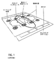
本発明は、図1に全体的に示すウェーハトラックシステムのような半導体処理装置に適用することができる。ウェーハトラックシステムは、基本的に3つの部分、つまり、カセットエンドインタフェース部分、スキャナインタフェース部分、及び処理部分を含む。カセットエンドインタフェース部分は、ウェーハをそれらが格納されているカセットからトラックシステムへ、また反対に、処理後にトラックシステムからカセットへ移送する装置を含む。スキャナインタフェース部分は、トラックシステムとフォトリソグラフィ装置との間でウェーハを移送するための装置を収容する別の移行区域であると考えることができる。他方、ウェーハトラックの処理部分は、基本的にレジストコーティングスピンモジュール、焼付け/冷却モジュール、及びレジスト現像スピンモジュールのようないくつかのウェーハ処理モジュールを含む。図1のシステムレイアウトに示すように、ウェーハトラック内の様々な処理スタックは、ある一定の利益とウェーハ処理効率を実現するために、組織的又は最適構成に配置することができる。例えば、いくつかの処理ステーションは、レジストコート及び現像処理のための処理モジュールのスタックを有する処理部分内に構成することができる。ウェーハを加熱及び冷却するために、焼付け/冷却プレートのような熱交換装置を有する熱モジュールのスタックを含むこともできる。図1に示す処理ステーションは、ウェーハ上に初期レジストコーティングを付加するための処理モジュールのスタックである一対のフォトレジストコーティング部分と、パターン化してレジストコーティングされたウェーハを現像するためのモジュールを備えた一対の現像部分とを含むことができる。ウェーハは、望ましいプログラムに従って又は所定の処理順序と合致した一組の命令に従って、一連のロボットアーム又は他のウェーハ操作装置を用いてトラックシステム内の処理ステーション間で配送及び移送することができる。 The present invention can be applied to a semiconductor processing apparatus such as a wafer track system shown generally in FIG. The wafer track system basically includes three parts: a cassette end interface part, a scanner interface part, and a processing part. The cassette end interface portion includes a device for transferring wafers from the cassette in which they are stored to the track system and vice versa. The scanner interface portion can be thought of as another transition area that houses an apparatus for transferring a wafer between the track system and the photolithographic apparatus. On the other hand, the processing portion of the wafer track basically includes several wafer processing modules such as a resist coating spin module, a bake / cool module, and a resist development spin module. As shown in the system layout of FIG. 1, the various processing stacks in a wafer track can be arranged in an organized or optimal configuration to achieve certain benefits and wafer processing efficiencies. For example, some processing stations can be configured in a processing section having a stack of processing modules for resist coating and development processing. It may also include a stack of thermal modules with heat exchange devices such as baking / cooling plates to heat and cool the wafer. The processing station shown in FIG. 1 includes a pair of photoresist coating portions that are a stack of processing modules for applying an initial resist coating on the wafer, and a module for developing the patterned and resist-coated wafer. A pair of development portions. Wafers can be delivered and transported between processing stations in the track system using a series of robotic arms or other wafer handling devices according to a desired program or according to a set of instructions consistent with a predetermined processing sequence.
半導体ウェーハ処理工程は、一組の高度に組織化された手順を含んでいる。ウェーハは、最初に、カセットエンドステーションに局所的に格納された1つ又はそれ以上のカセットからウェーハトラック内へ給送することができる。図1の平面図に示すように、一連のウェーハカセットは、カセット取付テーブル上で支持された4つの個別の縦列の組に配置することができる。ウェーハ運搬ロボットは、コントローラ(図示せず)から受け取った命令に応答して、ウェーハトラックシステム内の選択された処理モジュールから選択された処理モジュールへウェーハを移送するために望ましいカセットにアクセス可能である。ウェーハ又は基板上にフォトレジストフィルム層を形成する前に、ウェーハは、最初に準備モジュールに移送することができ、そこで、その表面は、水分の存在を取り除いて確実に疎水性の表面にするために熱処理又は化学処理をすることができる。次に、ウェーハは、冷却プレートのような熱装置を用いて冷却することができ、次にアプリケータへと搬送され、そこで、フォトレジストポリマーが、ウェーハ表面上に均一に分配される。フォトレジスト被覆ウェーハは、次に、フォトレジストポリマーを加熱してこれを安定なフィルムに変えるために、加熱装置又は焼成プレートへ移送することができる。加熱処理が完了した時、処理されたウェーハは冷却され、格納のためにカセットへ搬送されるか、又は、多くの場合にそうであるようにステッパ又はスキャナインタフェースを通じて付随するステッパ装置へ直接移送することができる。ウェーハ上のフォトレジストコーティング又はフィルムは、次に、ステッパ装置内で適用可能なフォトリソグラフィにより回路パターンに露光される。安定フィルムの露光後に、ウェーハは、トラックシステムへ戻され、フィルム上に回路パターンを定着させるために焼成モジュール内で加熱することができる。次に、ウェーハは、冷却モジュール内で冷却されて現像モジュールへ送られる。現像モジュール内では、フィルムの一部分を現像するためにフィルム上に溶液が加えられ、次に、ウェーハ表面から現像液を除去するためにウェーハ上に洗浄液が注がれる。次に、ウェーハは、焼成モジュール内で熱処理され、冷房モジュール内で冷却され、次に、格納のためにカセットへ戻すことができる。本発明によって提供される流体分配装置及び方法は、本明細書に説明したものを含む今日利用可能な多くの現像システムに適用することができる。 The semiconductor wafer processing process includes a set of highly organized procedures. Wafers can be initially fed into the wafer track from one or more cassettes stored locally at the cassette end station. As shown in the plan view of FIG. 1, a series of wafer cassettes can be arranged in sets of four individual columns supported on a cassette mounting table. A wafer handling robot can access a desired cassette for transferring wafers from a selected processing module in a wafer track system to a selected processing module in response to a command received from a controller (not shown). . Prior to forming the photoresist film layer on the wafer or substrate, the wafer can first be transferred to a preparatory module, where its surface is made hydrophobic by removing the presence of moisture. Can be heat treated or chemically treated. The wafer can then be cooled using a thermal device such as a cooling plate and then transferred to an applicator where the photoresist polymer is evenly distributed over the wafer surface. The photoresist-coated wafer can then be transferred to a heating device or baking plate to heat the photoresist polymer and convert it into a stable film. When the heat treatment is complete, the processed wafer is cooled and transported to a cassette for storage, or transferred directly to an associated stepper device through a stepper or scanner interface as is often the case. be able to. The photoresist coating or film on the wafer is then exposed to a circuit pattern by photolithography applicable in a stepper apparatus. After exposure of the stable film, the wafer can be returned to the track system and heated in a firing module to fix the circuit pattern on the film. The wafer is then cooled in the cooling module and sent to the development module. Within the development module, a solution is added on the film to develop a portion of the film, and then a cleaning solution is poured onto the wafer to remove the developer from the wafer surface. The wafer can then be heat treated in the firing module, cooled in the cooling module, and then returned to the cassette for storage. The fluid dispensing apparatus and method provided by the present invention can be applied to many development systems available today, including those described herein.
図2及び3に示すように、ウェーハトラックシステム内のレジストコーティングモジュールは、様々な流体分配アームを含むことができる。図2に示す構成は、直線レジストアーム、つまり、規定されたX軸線方向に沿って移動可能な直線運動をすることができるアーム20を示している。直線アーム20は、モジュール25内の様々な位置に沿って前後に運動するために一組のレールに沿って摺るように作られ、従来の電気的に作動するモータ24又は他の駆動機構によって駆動される。アーム20は、ウェーハWとレジスト溶液及び/又は流体供給ノズル26との間の距離を制御するために、相対的に垂直方向に動くようにも作ることができる。直線アーム20は、フォトレジスト溶液及び/又は洗浄液のような流体を分配するために、2つの別々のノズル26を含むことができる。ノズル26が図に示す定位置で休止している時にノズル26が乾燥するのを防止するために、ノズル浴槽27を設けることができる。更に、直線アーム20は、カップ又は格納容器29内に置かれた回転チャック28上に比較的平らに取り付けられたウェーハWの上方の選択された領域の上の分配位置へと移動させることができる。このように、様々な1つ又はそれ以上の流体をノズル26を通じてウェーハ上に分配することができる。これに加えて、様々な種類のレジスト溶液又は処理溶液を分配するために、ラジアル流体分配アーム30をモジュール25内に取り付けることができる。ラジアルアーム30が定位置又は待機位置に置かれている時、このアーム上に取り付けられた付加的なノズル36に対して別のノズル浴槽37を選択することができる。ラジアルアーム30は、本明細書に説明されているようなレジストコーティング処理中に所定の時間間隔で規定されたX−Y平面に沿って水平に、かつ下に重なるウェーハWの上方でこれを横切って選択的に掃引されるように、回転カップ29の近くにおいてレジストモジュール25内にピボット式に取り付けることができる。代替的に、図3に示すように、レジストコーティング又は処理モジュール35は、複数のラジアル流体分配アーム32を含むことができ、これらの各アームは、下に重なる半導体ウェーハのような基板S上に分配される流体を誘導するために、これらのアーム上に取り付けられた1つのノズル34を有する。各ラジアルアーム32は、回転カップ39の互いに相反する側に取り付けることができ、定位置又は休止位置に置かれた時に専用のノズル浴槽33を有することができる。1つ又はそれ以上の液体供給源に接続することができるノズル34を通じて基板S上に選択された流体を分配するために、一方又は両方のアーム32は、ウェーハ処理中に選択された時間間隔で基板Sの上方で遥動することができる。流体分配アーム32は、本明細書に説明した他の流体分配アームの場合と同様に、利用可能な駆動手段38によって駆動され、かつ制御することができる。
As shown in FIGS. 2 and 3, a resist coating module in a wafer track system can include various fluid distribution arms. The configuration shown in FIG. 2 shows a linear resist arm, that is, an
様々なコーティング処理は、図2及び3に示すような従来の装置を使用して行うことができる。例えば、ウェーハ又は基板のレジストコーティング時に、ウェーハは、最初に回転チャック又はプラットフォーム上に取り付けられる。通常はウェーハWの直上の区域の外側である待機位置又は定位置に保持することのできるレジストコーティング溶液供給ノズルは、フォトレジスト溶液を供給しながらウェーハの上方で掃引又は走査することができる。このノズルは、所定の期間中又は所望量の流体が放出された後に、一定のウェーハ位置に亘って溶液を誘導することができる。次に、供給ノズルは、待機位置又は定位置へ戻ることができる。所定量の時間が経過した後、コーティング処理は、実質的な完了に進むことができる。しかし、今日使用されている種類の処理装置を用いた場合には、供給ノズルは、ウェーハの上方を再び通過することがあるので、コーティングし終えたウェーハ上にレジスト溶液が滴下するかなり高い危険性がある。加圧された比較的大量の溶液は、多くの場合に比較的短時間の間にウェーハW上に迅速に分配されるので、滴下の危険性は更に増大する。レジスト溶液がウェーハ上に滴下する時、ウェーハの欠陥、線幅不良、ウェーハの形状不良、及び他の望ましくないウェーハ特性を含む多くの問題が生じる可能性がある。本明細書に説明する発明は、ウェーハ処理時における上述の限界を回避又は最小にするために、そのようなウェーハトラックシステム及びレジストコーティングモジュールに適用することができるものである。レジストコーティングの形成に関連した本発明の説明は、現像液及び他の処理溶液の分配にも同様に適用することができるということも更に理解されるものとする。 Various coating processes can be performed using conventional equipment as shown in FIGS. For example, during resist coating of a wafer or substrate, the wafer is first mounted on a rotating chuck or platform. A resist coating solution supply nozzle, which can be held in a standby or fixed position, usually outside the area directly above the wafer W, can sweep or scan over the wafer while supplying a photoresist solution. This nozzle can direct the solution over a certain wafer position for a predetermined period of time or after a desired amount of fluid has been released. The supply nozzle can then return to the standby position or home position. After a predetermined amount of time has elapsed, the coating process can proceed to substantial completion. However, with the type of processing equipment in use today, the supply nozzle may pass again over the wafer, so there is a fairly high risk that the resist solution will drip onto the coated wafer. There is. Since the relatively large amount of pressurized solution is often quickly distributed on the wafer W in a relatively short time, the risk of dripping is further increased. When the resist solution is dripped onto the wafer, a number of problems can occur, including wafer defects, linewidth defects, wafer shape defects, and other undesirable wafer characteristics. The invention described herein can be applied to such wafer track systems and resist coating modules to avoid or minimize the aforementioned limitations during wafer processing. It will be further understood that the description of the invention relating to the formation of a resist coating can be applied to the dispensing of developer and other processing solutions as well.
図4は、フォトレジストのような様々な処理溶液のコーティング又はフィルムを付加するために選択することができるウェーハトラックシステム内の処理モジュール40を示している。規定されたX−Y平面に沿って見た処理モジュール40のこの上面図に示すように、ウェーハW又は基板は、ロボットアーム42又は移送装置によってモジュール内へ移送されて回転チャック44上に置くことができる。回転チャック44は、捕捉カップ又はボウル46内に置かれ、モータ又は回転駆動機構によって駆動される。ウェーハWは、従来の真空吸引装置又は他の公知の装置を用いて回転チャック44上の定位置に保持することができる。更に、装置の底部又は側壁部分に沿って取り付けられた案内レール41上でX軸線方向に沿って摺動自在に動くように、1つ又はそれ以上の直線分配アームをモジュール40内に取り付けることができる。分配アーム42は、図に示すようにY軸線方向に沿って前後に延びる伸縮アームをもたらすために、伸張可能なセグメントA及びBで構成することができる。ラジアル又は直線分配アーム設計の場合、アーム42のいくつかの部分A及びBは、本発明のこの態様によれば、遠位側に取り付けられたシリンジ把持部50又はホルダを基板又は他の望ましい位置の上に位置決めするために、必要に応じて伸縮させることができる。ここに示したシリンジ把持部は、本明細書においてその全内容が引用により組み込まれている米国特許出願出願番号第10/320,994号に説明したアームのようなピボット回転可能ラジアルアームを含むモジュール内の他の種類の分配アーム上にも取付け可能であることは理解されるものとする。
FIG. 4 shows a
流体シリンジのトレイ48は、図4に示すように処理モジュール40内に置くことができる。流体シリンジ45は、ウェーハ又は基板上に配置されるレジスト溶液のような任意の様々な望ましい処理流体を収容することができる。各シリンジ45は、トレイ48内に形成された個々の区画47内に収容するか、又は同様な種類の流体を分配するために必要に応じてグループ毎にまとめることができる。更に、トレイ48又はシリンジの集合は、モジュール40の側壁又は他の部分に取り付けたトレイ軌道49上に摺動自在に取り付けることができる。シリンジトレイ48の可動性は、分配アーム42の要求された運動を助けるか又は低減することができる。トレイ48から望ましいシリンジが選択された時、分配アーム42は、その上に取り付けられた把持部50が望ましいシリンジと整列することができるように、トレイに向けて動くことができる。本発明のこの実施形態では、把持部50と望ましいシリンジの間の相互作用を妨げる処理流体配管は全くない。トレイ48は、静止位置に固定することができ、又はそうでなければ選択されたシリンジに対する把持部50の整列を助けるために動くことができる。分配アーム42と把持部50は、トレイ48から望ましいシリンジを把持し、スピンコーティングを形成するために、回転するウェーハ上方の望ましい位置にそのシリンジを位置決めすることができる。望ましい位置及び時点において、把持部50は、シリンジを作動させてその内容物を下に重なるウェーハ上に放出させることができる。シリンジ内の全所定量の流体を放出することにより、滴下の危険性が更に減少される。シリンジ内容物の分配に続いて、アーム42は、シリンジをトレイ48内の適正位置つまり定位置に戻すことができる。トレイ48から付加的なシリンジを選び、同様にウェーハW又は基板上に分配するために以上の諸作動を必要に応じて反復することができる。
The
本明細書において提供される調節可能な多重流体分配アレイは、ウェーハトラックモジュール内で使用されるレジスト溶液及び他の種類の処理流体を配置するために複数のシリンジを含むことができる。固定された長さ又は可変的な長さを有するロボット分配アームを用いることにより、流体分配装置を収容したトレイは、ロボットアームにより近く配置することができる。これによって、分配アームのみから要求される作業負荷を低減し、また時間を節減することができる。様々な公知のコントローラ(図示せず)は、アーム及び/又は流体分配トレイに要求される運動が最小となるように、アームとトレイの間の運動を調整することができる。分配アームとトレイに加わる共有の作業負荷は、ロボット分配アームのみによる運動を低減することにより、幾らかの時間節減をもたらすことになる。約2フィートx2フィートのレイアウトのような様々な寸法に形成することができるモジュール内で分配アームが限定された運動範囲を有する場合には、シリンジトレイは、そのような限度を補って、分配アーム把持部にアクセス可能なより多くのシリンジを保持することができる。多くの個々のシリンジを使用することができることは、いかなる流体ラインもアームを貫通して配管する必要がないという点で分配アームの構造を単純化させる。従って、分配される異なる流体の数は、流体分配アーム内に支持又は収容される流体ラインの数に限定されることはない。 The adjustable multi-fluid distribution array provided herein can include a plurality of syringes to place the resist solution and other types of processing fluids used in the wafer track module. By using a robot dispensing arm having a fixed or variable length, the tray containing the fluid dispensing device can be located closer to the robot arm. This reduces the workload required only from the dispensing arm and saves time. Various known controllers (not shown) can adjust the movement between the arm and tray so that the movement required for the arm and / or fluid distribution tray is minimized. The shared workload applied to the dispensing arm and tray will result in some time savings by reducing the motion by the robot dispensing arm alone. If the dispensing arm has a limited range of motion within a module that can be formed to various dimensions, such as a layout of about 2 feet x 2 feet, the syringe tray will compensate for such limitations and the dispensing arm More syringes accessible to the gripper can be held. The ability to use many individual syringes simplifies the structure of the dispensing arm in that no fluid lines need to be routed through the arm. Thus, the number of different fluids dispensed is not limited to the number of fluid lines supported or contained within the fluid dispensing arm.
図5は、ウェーハトラックモジュール40のX−Z平面に沿って見た時の図4に示す流体分配アーム及び把持部の別の図を示している。流体分配アーム42は、モジュール40の側壁部分上に取り付けられた軌道41に沿って置かれ、これに沿って摺ることができる。分配アーム42上に取り付けられた把持部50は、シリンジの主要本体部分55を把持又は固定することができるシリンジホルダ52を含むことができる。更に、把持部50は、シリンジのプランジャ部分56を固定するためにプランジャホルダ54を有するように形成される。プランジャホルダ54は、それ自体移動することができ、又は分配される流体を充填及び放出する指令に応じて、これを選択的に上下方向に上げ下げする可動的な作動部材51に取り付けることができる。本明細書に説明した処理モジュールのモータ駆動される他のアセンブリの場合と同様に、プランジャホルダ54の作動及び分配アーム42の全体的な移動は、1つ又はそれ以上のコントローラによって指令することができる。分配アーム42及び把持部50は、捕捉カップ46に隣接したモジュール40内の初期待機位置に保持することができる。指令された時、分配アーム42は、トレイ48から選択されたシリンジを取り出すことができる。選択されたシリンジは、他のシリンジと共用することができるそれぞれのリザーバ47の上方でトレイ48の一部分内に比較的直立した姿勢で格納することができる。異物の侵入を防止し、直立姿勢で立っている時にシリンジを容易に除去及び交換することができるように、可撓性フラップ蓋でリザーバ47を被うことができる。リザーバ47は、レジストのような処理流体を選択された分量だけ保持するようにトレイ48内に形成することができる。リザーバ47は、外部液体供給源に通じる供給管58に流体連通することができる。更に、トレイ48は、リザーバ47及び/又は供給管58の比較的近くに置かれた熱交換器53を含んでいる。この熱交換器は、シリンジによって分配される流体を望ましい温度に維持することができる。望ましい流体温度を得るために、ペルチェ素子及び熱抵抗器のような様々な公知の熱交換装置を選択することができる。従来のノズルとホースから成るアセンブリを備えた比較的長い供給管に熱交換流体を循環させるのではなく、選択された容積の流体を必要に応じて冷却又は加熱し、必要に応じてより小さな容積の流体で高度に効率的な熱交換を行うことができる。シリンジトレイ48は、様々な流体を異なる温度に維持するために、個々のリザーバに対して個々の熱交換器を含むことができる。本明細書に示す発明の他の実施形態は、流体をリザーバ内に中間的に格納することなく、トレイ内に格納されたシリンジ内に直接給送することができるものである。
FIG. 5 shows another view of the fluid distribution arm and gripper shown in FIG. 4 when viewed along the XZ plane of the
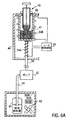
図6Aに示すように、流体分配シリンジ45は、液体供給源61に対して流体連通することができる。液体供給源61は、格納された溶液を望ましい温度に維持するために熱交換器63を含むことができる。液体供給源61は、液体供給源管64を通じて流体を給送するポンプ62に接続することができる。ポンプ62は、独立的に作動することができ、又は外部液体供給源からシリンジトレイ48内に流体を供給するように選択することができる他のポンプと連携して作動することができる。ポンプ62により給送される流体は、シリンジトレイ48内に形成された1つ又はそれ以上のリザーバ47にシリンジ管65を通じて送ることができる。代替的に、重力支援設計を用いて流体が上方からリザーバ47内に供給される場合、又はリザーバ47内に手動的に注入される場合には、いかなるポンプも必要とされない。複数のシリンジは、共通のリザーバを共用することができ、又は、各々は、分配される同一種類の流体を受け取ることができる。図6Bに示すような本発明の別の実施形態では、いかなるリザーバも必要とされない。ポンプ62からの流体は、直接シリンジ45に送ることができる。トレイ48内の開口部67は、流体をシリンジ管65を通じてシリンジ45内へ給送することを可能にする。シリンジ45に対する流体密封シ−ルを形成するように一連の弁又はシ−ル66を選択することができる。本発明の更に別の実施形態では、使い捨て可能な1回使用型シリンジをトレイ48内に密封して格納することができ、この場合、シリンジは、分配される一定量のフォトレジスト溶液又は処理溶液を前以って収容しており、使用後は廃棄することができる。処理溶液61は、必要とされるまで格納することができ、そのそれぞれの熱交換器63により望ましい温度に保つことができる。分配される流体のための望ましい温度制御に応じて、図示のシリンジトレイ熱交換器53A及び53Bのいずれか一方又は両方を一定の用途のために選択し、温度制御装置55により制御することができる。シリンジトレイに通じた流体ポンプ及び供給管の1つ又はそれ以上の組合せに接続した複数の処理溶液を分配することができるということは理解されるものとする。
As shown in FIG. 6A, the
図7は、処理溶液をシリンジに充填し又はシリンジから放出する分配アーム把持部の作動を示している。分配アーム把持部70は、シリンジ75のプランジャ部分76と本体部分77の両方と係合することができる。把持部70のホルダ部分72は、選択されたシリンジの本体部分77と係合することができ、同様に、プランジャホルダ部分74は、充填された位置又は充填されていない位置(仮想線で示す)に保つことのできるシリンジプランジャ76と係合することができる。充填された位置において、プランジャ76は、既に比較的上方に後退させられており、所定量の流体をシリンジ75内に収容している。他方、充填されていない位置において、シリンジ75は、分配される望ましい量の流体を未だ収容していないか又はその流体を既に分配し終えている。望ましい流体を充填する時、シリンジホルダ72は、シリンジ75を確実に保持することができ、他方、プランジャホルダ74は、流体をリザーバからシリンジ内へ流入させるためにプランジャ76を引き上げる、つまり後退させることができる。プランジャホルダ74は、シリンジ75に充填及び放出させるために上下動する分配アーム78に接続した作動部材71を含むことができる。今日では、バイオテクノロジー産業において利用されるものを含む様々なシリンジ及びピペットが利用可能なことは理解されるものとする。これらの流体分配装置の各々に対する作動機構に応じて、分配アーム把持部は、本発明によりそれぞれを選択的に把持して作動させるように構成することができる。更に、ここで選択されるシリンジは、充填されて再使用されるものではなく、比較的廉価で使用後に廃棄することができる使い捨ての1回使用型流体送出装置である。
FIG. 7 shows the operation of the dispensing arm gripper that fills or releases the treatment solution into the syringe. The dispensing
本発明の別の態様は、本明細書に説明した装置を用いて、実質的に滴下することなく半導体ウェーハをレジストコーティングする様々な方法を提供する。例えば、レジストコーティングモジュールには、少なくとも1つの流体シリンジを把持するために把持部をその遠位側に取り付けるように形成された分配アームを設けることができる。この分配アームは、モジュール内のトレイから望ましいシリンジを選択して把持するように指令することができる。次に、分配アーム及びシリンジは、回転チャック上に取り付けられた回転するウェーハを収容する捕捉カップの上方のようなモジュール内の望ましい位置に位置決めすることができる。次に、把持部は、シリンジの内容物をウェーハ上に分配してレジストコーティングを形成するために、シリンジのプランジャ部分を下降させることにより、シリンジを外すか又は作動させることができる。次に、分配アームは、シリンジをトレイの区画内に戻すように指令される。この区画は、シリンジを下降させて溶液を引き込むことができるように、レジスト溶液を収容することができる。分配アーム把持部は、シリンジを装填し、つまりプランジャを後退させ、シリンジが再び流体を直ちに分配することができるように、又はシリンジを待機装填位置に保つことができるように指令される。ここに説明したシリンジは、様々なサイズに形成することができ、約0.5から5.0cc又はそれ以上の範囲の流体容積を収容することができるということは理解されるものとする。 Another aspect of the present invention provides various methods for resist coating a semiconductor wafer without substantially dripping using the apparatus described herein. For example, the resist coating module can be provided with a dispensing arm configured to attach a gripping portion distally to grip at least one fluid syringe. The dispensing arm can be instructed to select and grasp the desired syringe from the tray in the module. The dispensing arm and syringe can then be positioned at a desired location within the module, such as above a capture cup that houses a rotating wafer mounted on a rotating chuck. The gripper can then remove or actuate the syringe by lowering the plunger portion of the syringe to dispense the syringe contents onto the wafer to form a resist coating. The dispensing arm is then commanded to return the syringe into the compartment of the tray. This compartment can contain the resist solution so that the syringe can be lowered to draw the solution. The dispensing arm grip is commanded to load the syringe, i.e., retract the plunger, so that the syringe can immediately dispense fluid again, or to keep the syringe in the standby loading position. It should be understood that the syringes described herein can be formed in a variety of sizes and can accommodate fluid volumes in the range of about 0.5 to 5.0 cc or more.
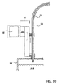
図8から11は、本発明の更に別の実施形態を示しており、この実施形態は、個々の流体分配ライン及びノズルのアレイを使用した流体分配システムを提供している。トレイに取り付けられた流体分配ライン85のアレイを近くに設けることにより、分配アーム82は、毎回全ての流体ラインに流体を充填して搬送するのではなく、必要に応じて個々の流体ラインを個別的に選択することができる。いくつかの流体ライン85は、一般的に、長さ3から6フィートであって、異なる種類の処理溶液を分配することができるように形成され、従って、分配アーム82の物理的パラメータによって限定されない。図8及び9に示すように、分配アーム82は、上述のような1つ又はそれ以上の把持部90を有する構造に作ることができる。一連のコントローラは、ウェーハW又は基板を取り付けた回転カップ86又はチャック84に対して分配アーム82をモジュール80内の様々な領域に沿って位置決めすることができる。分配アーム把持部90は、望ましい処理溶液を分配するために、トレイ88上の浴槽内に格納されている選択されたノズル95に整列することができる。トレイ88は、軌道89上に摺動可能に取り付けることができる。把持部90は、図10に示すように、必要に応じて選択されたノズル95を把持するために、1つ又はそれ以上のホルダ92及び94を有するように形成することができる。把持部90の上下運動を助けるために、別の作動部材101を設けることもできる。各ノズル95は、個々の管又は熱ジャケット93内に収容された供給管85に接続することができ、この場合、各供給管は、外部液体供給源91及び図11に示すような市販のシリンジポンプ100(カブロ・インコーポレーテッド、米国カルフォルニア州サンホセ)に接続することができる。これらのそれぞれ別々の弁機構96を含む一連又は一列の流体シリンジポンプ100は、流体を分配するために中央コントローラ110により独立的に作動又は制御することができる。代替的に、流体をシリンジ100に出入りさせるために受動弁を選択することができる。各管93は、供給管85及びこれに含まれた流体を望ましい温度又は望ましい温度範囲に維持するために、循環する熱交換媒体又は要素103を含むことができる。中央コントローラ110は、様々な弁102を用いて流体の温度及び流れを制御することができ、かつ媒体を冷却及び加熱することができる。滴下の危険性を更に低減するために、当業技術で公知のように、1つ又はそれ以上のシリンジポンプ100の組合せを流体ライン85の様々な部分に沿って取り付けることができる。本明細書において提供される単一管流体ディスペンサは、各ノズルと管のアセンブリに対して個々のポンプを使用して相互汚染の危険性を低減し、高度に制御された流体放出を行うことができるものである。
FIGS. 8 through 11 illustrate yet another embodiment of the present invention, which provides a fluid distribution system using an array of individual fluid distribution lines and nozzles. By providing a close array of
処理モジュール内の異なる位置において把持部を移動させるために、様々な流体分配アームを選択することができる。流体的に安定な環境内で極めて正確な処理手順を行うために、多くのウェーハトラック処理モジュールは、望ましい層流気流を備えている。ウェーハトラックモジュール内の従来の流体分配アームは、一般的に直線ハードエッジ設計形状を有し、単純な矩形設計形状を有するように形成され、アームの遠位端に取り付けられたノズル内に流体を供給する配管を収容するために中空である。逆U字形状の断面を有する分配アームが一般的に使用され、この場合、配管は、アームの下方に収容され、実質的に目に触れないようにアームの中空部分内に置かれる。しかし、分配アームの非空気力学的エッジは、回転する基板の近くに乱気流を作り出す可能性がある。アームが基板表面の近くで掃引される時、この従来のアーム形状は、空気流を分断してフォトレジストのような材料の平坦又は均一なコーティング厚に悪影響を及ぼすことになる。トラックモジュールを有するいくつかの構成要素が移動する速度と、密封された環境内で流体が分配される割合とを考慮した場合、実質的に直線的な空気流をモジュール内で維持することが望ましい。 Various fluid distribution arms can be selected to move the gripper at different locations within the processing module. Many wafer track processing modules have the desired laminar airflow in order to perform very accurate processing procedures in a fluidly stable environment. Conventional fluid distribution arms in a wafer track module generally have a straight hard edge design shape and are formed to have a simple rectangular design shape, with fluid flowing into a nozzle attached to the distal end of the arm. It is hollow to accommodate the supply piping. Distributing arms having an inverted U-shaped cross-section are commonly used, in which case the tubing is housed below the arms and placed within the hollow portion of the arms so that it is substantially invisible. However, the non-aerodynamic edge of the distribution arm can create turbulence near the rotating substrate. When the arm is swept near the substrate surface, this conventional arm shape will disrupt the air flow and adversely affect the flat or uniform coating thickness of materials such as photoresist. Considering the speed at which several components with track modules move and the rate at which fluid is distributed within the sealed environment, it is desirable to maintain a substantially linear air flow within the module. .
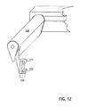
本発明の別の態様によれば、流体分配アームは、図12に示すような空気力学的な翼として構成することができる。空気力学的構造に作られた流体分配アームは、レジストコーティング及び現像ユニットのような様々なウェーハトラック処理モジュール内で使用することができる。分配アーム120は、テーパを付され、比較的小さな湾曲側面下側部分に対して比較的大きな湾曲側面上側部分を含んでいる。本明細書に説明した他の把持アセンブリ125の場合と同様に、分配アーム120の相対的に遠位側の端部部分に一対のホルダ122及び124を取り付けることができる。他の翼設計一般の場合と同様に、本実施例における流体分配アームは、モジュール内で意図される乱気流に悪影響を及ぼさないように滑らかな表面を有するように形成することができる。本明細書に説明した多重流体分配シリンジ又はノズル/管アレイに対して選択された分配アームを含む、分配アーム内の中空空洞を通して配管が延びていないいくつかの分配アームについては、回転する表面に対向したアームの下方領域は、空気を捕らえたり又はその他の方法でモジュール内に必要な望ましい滑らかな空気流を乱さないものである。従って、本明細書において提供される単純化された分配アーム設計は、流体のより均一な分布とウェーハ欠陥の可能性の低減とをもたらすことができる滑らかな流体分配結果を与えるものである。
According to another aspect of the invention, the fluid distribution arm can be configured as an aerodynamic wing as shown in FIG. Fluid distribution arms made to aerodynamic structures can be used in various wafer track processing modules such as resist coating and developing units. The dispensing
本明細書において提供される分配アームは、図13Aから13Eに示すような様々な把持部を有するように構成することができる。本明細書において使用される「把持部」という用語は、能動的把持機構と受動的把持機構の両方を含むということは理解されるものとする。能動的な把持機能を果たすために、様々な機械的及び磁力的に作動する把持アセンブリが本発明によって提供される。例えば、把持部は、処理流体又は溶液トレイから分配ノズル又はシリンジを把持するために、1つ又はそれ以上のホルダ部分を含むことができる。把持部は、図13Aから13Cに示すように、シリンジ130又はノズルをそれぞれ把持又は解放するために、近付けたり遠ざけたりすることができる2つの相対する部材132及び134を含むことができる。ここでは互いに相補的に摺動可能に係合する把持部ホルダの一部分及びシリンジ130のプランジャ又は本体部分上に、一連の溝及びスロットを形成することができる。代替的に、図13Dに示すように、複数の交互に相対する部材又はフィンガ部分135を機械的に作動させて開閉することができる。把持部はまた、図13Eに示すように、シリンジ又はノズル上の別のプレートと係合及び外れるように磁力によって作動するプレートを含むことができる。本発明の他の実施形態はまた、十分な力が加えられた時に物体を選択的に保持及び解除するバネ作動式部材のような受動的な把持装置を含むことができる。
The dispensing arms provided herein can be configured to have various grippers as shown in FIGS. 13A to 13E. It is to be understood that the term “grip” as used herein includes both active and passive gripping mechanisms. Various mechanically and magnetically actuated gripping assemblies are provided by the present invention to perform an active gripping function. For example, the gripper can include one or more holder portions to grip the dispensing nozzle or syringe from the processing fluid or solution tray. The gripper can include two opposing
本発明を以上の明細書に関連して説明したが、本明細書の好ましい実施形態の説明及び図面は、限定的な意味で解釈されないものとする。本発明の全ての態様は、様々な条件及び変数に依存する本明細書に示す特定の説明、構成、又は相対的な比率に限定されないことは理解されるものとする。本発明の実施形態の形式及び詳細の様々な変更、並びに本発明の他の変形は、本発明の開示内容を参照すると当業者には明らかであろう。従って、特許請求の範囲はまた、いかなるそのような修正、変形、又は均等物をも網羅するように意図するものである。 Although the invention has been described in connection with the foregoing specification, the description of the preferred embodiments and drawings in this specification are not to be construed in a limiting sense. It should be understood that all aspects of the invention are not limited to the specific descriptions, configurations, or relative proportions set forth herein which depend on various conditions and variables. Various modifications in form and detail of the embodiments of the invention, as well as other variations of the invention, will be apparent to those skilled in the art upon review of the disclosure of the invention. Accordingly, the claims are also intended to cover any such modifications, variations, or equivalents.
40 処理モジュール
42 ロボットアーム
44 回転チャック
45 流体シリンジ
W ウェーハ
40
Claims (7)
捕捉カップ内に置かれた回転チャックを収容したウェーハトラックコーティングモジュールと、
前記ウェーハトラックコーティングモジュール内の流体シリンジを把持して位置決めするための分配アーム及び把持部アセンブリと、
前記ウェーハトラックコーティングモジュール内に配置された、フォトレジスト溶液を収容する複数の流体シリンジを保持するための溶液トレイと、
を含むことを特徴とするシステム。 A multi-syringe fluid dispensing system for photoresist coating comprising:
A wafer track coating module containing a rotating chuck placed in a catch cup;
A dispensing arm and gripper assembly for gripping and positioning a fluid syringe in the wafer track coating module;
A solution tray disposed within the wafer track coating module for holding a plurality of fluid syringes containing a photoresist solution;
A system characterized by including.
処理モジュール内のトレイ上に取り付けられた流体ディスペンサのアレイ、
を含み、
各流体ディスペンサは、該流体ディスペンサの相対的に遠位側の領域に形成されたノズル部分、該流体ディスペンサの長さに沿って該ノズル部分まで延びる流体ライン、及び熱伝達媒体を循環させて該流体ライン内の流体の温度を制御するための該流体ラインを取り囲む熱ジャケットを含み、
選択された流体ディスペンサの選択されたノズル部分を把持するように構成された装着把持部を支持し、かつ該選択されたノズル部分を前記処理モジュール内の所定の位置へ誘導することができる分配アームと、
フォトレジスト溶液供給源と前記選択された流体ディスペンサの流体ラインとに流体連通した流体シリンジポンプアセンブリと、
前記流体シリンジポンプアセンブリと、前記選択された流体ディスペンサの前記選択されたノズル部分を通る前記フォトレジスト溶液供給源からの流体の分配とを制御するためのコントローラと、
を更に含むことを特徴とする装置。 An apparatus for dispensing a plurality of photoresist solutions,
An array of fluid dispensers mounted on a tray in a processing module;
Including
Each fluid dispenser circulates a nozzle portion formed in a relatively distal region of the fluid dispenser, a fluid line extending to the nozzle portion along the length of the fluid dispenser, and a heat transfer medium. A thermal jacket surrounding the fluid line for controlling the temperature of the fluid in the fluid line;
A dispensing arm capable of supporting a mounting grip configured to grip a selected nozzle portion of a selected fluid dispenser and directing the selected nozzle portion to a predetermined location within the processing module When,
A fluid syringe pump assembly in fluid communication with a photoresist solution source and a fluid line of the selected fluid dispenser;
A controller for controlling the fluid syringe pump assembly and the dispensing of fluid from the photoresist solution source through the selected nozzle portion of the selected fluid dispenser;
The apparatus further comprising:
流体シリンジと係合して作動させる把持部を支持するための分配アームと半導体ウェーハを支持するための回転チャックとを含むウェーハトラックシステム内のコーティングモジュールを選択する段階と、
フォトレジスト溶液を収容した流体シリンジを前記コートモジュール内に格納する段階と、
前記流体シリンジを選択して解除可能に係合するように前記分配アーム及び前記把持部に命令する段階と、
前記把持部を備えた前記分配アームと前記流体シリンジとを前記半導体ウェーハの上の前記コートモジュール内の所定位置に誘導する段階と、
前記流体シリンジをそこに収容された前記フォトレジスト溶液を前記半導体ウェーハ上に分配するために作動するように前記把持部に命令する段階と、
を含むことを特徴とする方法。 A method for dispensing photoresist in a wafer track module comprising:
Selecting a coating module in a wafer track system that includes a dispensing arm for supporting a gripper that engages and operates with a fluid syringe and a rotating chuck for supporting a semiconductor wafer;
Storing a fluid syringe containing a photoresist solution in the coat module;
Instructing the dispensing arm and the gripper to select and releasably engage the fluid syringe;
Guiding the dispensing arm with the gripping portion and the fluid syringe to a predetermined position in the coat module on the semiconductor wafer;
Instructing the gripper to operate the fluid syringe to dispense the photoresist solution contained therein onto the semiconductor wafer;
A method comprising the steps of:
を更に含むことを特徴とする請求項5に記載の方法。 Dispensing the photoresist solution as it rotates on a substantially central portion of the semiconductor wafer;
The method of claim 5, further comprising:
を更に含むことを特徴とする請求項5に記載の方法。 Returning the distribution arm and gripping portion to the standby position in the coat module;
The method of claim 5, further comprising:
Applications Claiming Priority (2)
| Application Number | Priority Date | Filing Date | Title |
|---|---|---|---|
| US10/372,028 US7041172B2 (en) | 2003-02-20 | 2003-02-20 | Methods and apparatus for dispensing semiconductor processing solutions with multi-syringe fluid delivery systems |
| PCT/US2004/005120 WO2004075264A2 (en) | 2003-02-20 | 2004-02-20 | Methods and apparatus for dispensing semiconductor processing solutions with multi-syringe fluid delivery systems |
Publications (2)
| Publication Number | Publication Date |
|---|---|
| JP2006518931A true JP2006518931A (en) | 2006-08-17 |
| JP4227171B2 JP4227171B2 (en) | 2009-02-18 |
Family
ID=32907686
Family Applications (1)
| Application Number | Title | Priority Date | Filing Date |
|---|---|---|---|
| JP2006501184A Expired - Fee Related JP4227171B2 (en) | 2003-02-20 | 2004-02-20 | Method and apparatus for dispensing semiconductor processing solutions using a multi-syringe fluid dispensing system |
Country Status (5)
| Country | Link |
|---|---|
| US (2) | US7041172B2 (en) |
| JP (1) | JP4227171B2 (en) |
| KR (1) | KR101028520B1 (en) |
| CN (1) | CN100399499C (en) |
| WO (1) | WO2004075264A2 (en) |
Cited By (3)
| Publication number | Priority date | Publication date | Assignee | Title |
|---|---|---|---|---|
| JP2007216148A (en) * | 2006-02-16 | 2007-08-30 | Fuji Mach Mfg Co Ltd | High viscosity fluid application system |
| JP2008194579A (en) * | 2007-02-09 | 2008-08-28 | Fuji Mach Mfg Co Ltd | Temperature controller for adhesive dispenser |
| JP2015115486A (en) * | 2013-12-12 | 2015-06-22 | 東京エレクトロン株式会社 | Liquid supply device |
Families Citing this family (26)
| Publication number | Priority date | Publication date | Assignee | Title |
|---|---|---|---|---|
| US7041172B2 (en) * | 2003-02-20 | 2006-05-09 | Asml Holding N.V. | Methods and apparatus for dispensing semiconductor processing solutions with multi-syringe fluid delivery systems |
| US8353634B2 (en) * | 2003-06-06 | 2013-01-15 | Intel Corporation | Mounting a planar light wave circuit in a housing |
| WO2006108280A1 (en) * | 2005-04-12 | 2006-10-19 | O'hara Technologies Inc. | Continuous feed tablet coating system |
| JP4341686B2 (en) * | 2007-02-23 | 2009-10-07 | セイコーエプソン株式会社 | Film forming apparatus and film forming method |
| KR100865475B1 (en) * | 2007-08-30 | 2008-10-27 | 세메스 주식회사 | Nozzle assembly, processing liquid supply apparatus having the same, and processing liquid supply method using the same |
| US7767025B2 (en) * | 2007-09-30 | 2010-08-03 | Intel Corporation | Nozzle array configuration to facilitate deflux process improvement in chip attach process |
| FR2938116B1 (en) * | 2008-11-04 | 2011-03-11 | Aplinov | METHOD AND DEVICE FOR HEATING A LAYER OF A PLATE BY PRIMING AND LUMINOUS FLUX |
| KR101036592B1 (en) * | 2008-11-28 | 2011-05-24 | 세메스 주식회사 | Processing liquid supply unit and substrate processing apparatus using the same |
| KR101337368B1 (en) | 2010-10-27 | 2013-12-05 | 엘지디스플레이 주식회사 | Coating apparatus and method of forming coating layer using the same |
| US8882919B2 (en) * | 2010-12-23 | 2014-11-11 | Intermolecular, Inc. | Combinatorial non-contact wet processing |
| JP5845633B2 (en) * | 2011-05-26 | 2016-01-20 | セイコーエプソン株式会社 | Droplet discharge device |
| JP2013004614A (en) * | 2011-06-14 | 2013-01-07 | Toshiba Corp | Coating film forming method and coating film forming device |
| RU2641123C2 (en) * | 2013-10-11 | 2018-01-16 | Трэнсиженс Оптикал, Инк. | Device for application of multi-layer coating to optical flat by centrifuging method |
| CN105319855B (en) * | 2014-06-25 | 2020-02-07 | 沈阳芯源微电子设备股份有限公司 | Glue head and rubber tube integrated motion structure |
| CN108321263A (en) * | 2014-07-15 | 2018-07-24 | 首尔半导体股份有限公司 | Wavelength conversion section manufacturing device |
| JP6352824B2 (en) * | 2015-01-23 | 2018-07-04 | 東芝メモリ株式会社 | Substrate processing apparatus, control program, and control method |
| JP6527716B2 (en) * | 2015-02-27 | 2019-06-05 | 株式会社Screenホールディングス | Substrate processing apparatus and control method of substrate processing apparatus |
| US9915633B2 (en) * | 2015-07-28 | 2018-03-13 | The Boeing Company | Two-dimensional array depression profiler and measurement device |
| KR102385264B1 (en) * | 2015-08-28 | 2022-04-13 | 세메스 주식회사 | Apparatus and method for treating a substrate |
| CN109314070B (en) * | 2016-07-01 | 2022-10-18 | 卡本有限公司 | Method and system for spin-coating multilayer thin films with liquid retention features |
| JP7073691B2 (en) * | 2017-11-30 | 2022-05-24 | 東京エレクトロン株式会社 | Liquid treatment equipment and liquid treatment method |
| IT201900016925A1 (en) * | 2019-09-23 | 2021-03-23 | Altergon Sa | Punch for syringe pump for soft capsule encapsulating machine, and syringe pump comprising one or more of said punches |
| DE102020126216A1 (en) * | 2020-04-29 | 2021-11-04 | Taiwan Semiconductor Manufacturing Co., Ltd. | Method and device for coating a substrate with photoresist |
| KR20210153298A (en) * | 2020-06-10 | 2021-12-17 | 실이엔지 주식회사 | Capsule type chemical solution supply apparatus and chemical solution supply method using the same |
| CN117321751A (en) * | 2021-04-25 | 2023-12-29 | 盛美半导体设备(上海)股份有限公司 | Substrate processing equipment |
| US20230259033A1 (en) * | 2022-02-11 | 2023-08-17 | STATS ChipPAC Pte. Ltd. | Semiconductor Device and Method of Applying a Single Liquid Photoresist Material to Semiconductor Wafer |
Citations (9)
| Publication number | Priority date | Publication date | Assignee | Title |
|---|---|---|---|---|
| JPS60251623A (en) * | 1984-05-28 | 1985-12-12 | Nec Corp | Liquid material discharging device for semiconductor device |
| JPH01146524U (en) * | 1988-03-31 | 1989-10-09 | ||
| JPH07283104A (en) * | 1994-04-06 | 1995-10-27 | Ryoden Semiconductor Syst Eng Kk | Chemical coating device |
| JPH08222498A (en) * | 1995-02-09 | 1996-08-30 | Oki Electric Ind Co Ltd | Chemical liquid ejection device in resist coater |
| JPH10289872A (en) * | 1997-04-14 | 1998-10-27 | Dainippon Screen Mfg Co Ltd | Chemical feeding device |
| JP2000167466A (en) * | 1998-12-01 | 2000-06-20 | Nec Corp | Liquid chemical coating machine and its usage |
| JP2001351847A (en) * | 2000-06-06 | 2001-12-21 | Nippon Foundry Inc | Semiconductor manufacturing equipment |
| JP2002153795A (en) * | 2000-11-16 | 2002-05-28 | Advanced Color Tec Kk | Single wafer substrate manufacturing method and coating apparatus |
| JP2004172201A (en) * | 2002-11-18 | 2004-06-17 | Tokyo Electron Ltd | Substrate processing apparatus and substrate processing method |
Family Cites Families (29)
| Publication number | Priority date | Publication date | Assignee | Title |
|---|---|---|---|---|
| US4030640A (en) * | 1975-11-10 | 1977-06-21 | Indicon Inc. | Method and apparatus for dispensing viscous materials |
| US4500247A (en) * | 1982-05-03 | 1985-02-19 | Eli Lilly And Company | Syringe inspection apparatus |
| US5002008A (en) * | 1988-05-27 | 1991-03-26 | Tokyo Electron Limited | Coating apparatus and method for applying a liquid to a semiconductor wafer, including selecting a nozzle in a stand-by state |
| US5212050A (en) * | 1988-11-14 | 1993-05-18 | Mier Randall M | Method of forming a permselective layer |
| US5033656A (en) * | 1989-02-21 | 1991-07-23 | Minnesota Mining And Manufacturing Company | Method and apparatus for precision squeeze tube valving, pumping and dispensing of work fluid (s) |
| EP0618504B1 (en) | 1993-03-25 | 2001-09-26 | Tokyo Electron Limited | Method of forming coating film and apparatus therefor |
| JPH06343979A (en) * | 1993-06-08 | 1994-12-20 | Meidensha Corp | Corrosion control device for water supply and distribution pipe |
| TW285779B (en) * | 1994-08-08 | 1996-09-11 | Tokyo Electron Co Ltd | |
| JP3275202B2 (en) | 1996-08-30 | 2002-04-15 | 東京エレクトロン株式会社 | Thin film forming equipment |
| JP3333121B2 (en) | 1996-12-25 | 2002-10-07 | 東京エレクトロン株式会社 | Coating device |
| JP3410342B2 (en) | 1997-01-31 | 2003-05-26 | 東京エレクトロン株式会社 | Coating device |
| US6045755A (en) * | 1997-03-10 | 2000-04-04 | Trega Biosciences,, Inc. | Apparatus and method for combinatorial chemistry synthesis |
| JPH1133471A (en) | 1997-07-23 | 1999-02-09 | Tokyo Electron Ltd | Coating device |
| KR100271759B1 (en) * | 1997-07-25 | 2000-12-01 | 윤종용 | Photoresist Coating Apparatus and Method |
| US6183810B1 (en) | 1998-01-21 | 2001-02-06 | Tokyo Electron Limited | Coating film forming method and coating apparatus |
| US6214117B1 (en) * | 1998-03-02 | 2001-04-10 | Speedline Technologies, Inc. | Dispensing system and method |
| JP3445937B2 (en) | 1998-06-24 | 2003-09-16 | 東京エレクトロン株式会社 | Multi-stage spin type substrate processing system |
| JP3461725B2 (en) | 1998-06-26 | 2003-10-27 | 東京エレクトロン株式会社 | Treatment liquid supply device and treatment liquid supply method |
| US6280799B1 (en) * | 1998-12-28 | 2001-08-28 | Dai Nippon Printing Co., Ltd. | Viscous substance discharging method using a viscous substance dispenser and pattern forming method using a viscous substance dispenser |
| KR100585448B1 (en) | 1999-04-08 | 2006-06-02 | 동경 엘렉트론 주식회사 | Film Formation Method and Film Forming Device |
| JP3616275B2 (en) | 1999-05-31 | 2005-02-02 | 東京エレクトロン株式会社 | Liquid treatment apparatus, treatment liquid supply nozzle used therefor, and liquid treatment method |
| US6364547B1 (en) | 1999-10-25 | 2002-04-02 | Tokyo Electron Limited | Solution processing apparatus |
| US6384894B2 (en) | 2000-01-21 | 2002-05-07 | Tokyo Electron Limited | Developing method and developing unit |
| US6598765B2 (en) * | 2000-06-30 | 2003-07-29 | Brewer Science, Inc. | Disposable syringe dispenser system |
| JP3587776B2 (en) * | 2000-10-10 | 2004-11-10 | 東京エレクトロン株式会社 | Coating device and coating method |
| US6706641B2 (en) * | 2001-09-13 | 2004-03-16 | Micell Technologies, Inc. | Spray member and method for using the same |
| US6770424B2 (en) | 2002-12-16 | 2004-08-03 | Asml Holding N.V. | Wafer track apparatus and methods for dispensing fluids with rotatable dispense arms |
| US7041172B2 (en) | 2003-02-20 | 2006-05-09 | Asml Holding N.V. | Methods and apparatus for dispensing semiconductor processing solutions with multi-syringe fluid delivery systems |
| DE102005023203B4 (en) * | 2005-05-20 | 2009-06-04 | Eppendorf Ag | pipette |
-
2003
- 2003-02-20 US US10/372,028 patent/US7041172B2/en not_active Expired - Lifetime
-
2004
- 2004-02-20 JP JP2006501184A patent/JP4227171B2/en not_active Expired - Fee Related
- 2004-02-20 CN CNB2004800048698A patent/CN100399499C/en not_active Expired - Fee Related
- 2004-02-20 WO PCT/US2004/005120 patent/WO2004075264A2/en not_active Ceased
- 2004-02-20 KR KR1020057015450A patent/KR101028520B1/en not_active Expired - Fee Related
-
2006
- 2006-01-30 US US11/343,368 patent/US7485346B2/en not_active Expired - Lifetime
Patent Citations (9)
| Publication number | Priority date | Publication date | Assignee | Title |
|---|---|---|---|---|
| JPS60251623A (en) * | 1984-05-28 | 1985-12-12 | Nec Corp | Liquid material discharging device for semiconductor device |
| JPH01146524U (en) * | 1988-03-31 | 1989-10-09 | ||
| JPH07283104A (en) * | 1994-04-06 | 1995-10-27 | Ryoden Semiconductor Syst Eng Kk | Chemical coating device |
| JPH08222498A (en) * | 1995-02-09 | 1996-08-30 | Oki Electric Ind Co Ltd | Chemical liquid ejection device in resist coater |
| JPH10289872A (en) * | 1997-04-14 | 1998-10-27 | Dainippon Screen Mfg Co Ltd | Chemical feeding device |
| JP2000167466A (en) * | 1998-12-01 | 2000-06-20 | Nec Corp | Liquid chemical coating machine and its usage |
| JP2001351847A (en) * | 2000-06-06 | 2001-12-21 | Nippon Foundry Inc | Semiconductor manufacturing equipment |
| JP2002153795A (en) * | 2000-11-16 | 2002-05-28 | Advanced Color Tec Kk | Single wafer substrate manufacturing method and coating apparatus |
| JP2004172201A (en) * | 2002-11-18 | 2004-06-17 | Tokyo Electron Ltd | Substrate processing apparatus and substrate processing method |
Cited By (3)
| Publication number | Priority date | Publication date | Assignee | Title |
|---|---|---|---|---|
| JP2007216148A (en) * | 2006-02-16 | 2007-08-30 | Fuji Mach Mfg Co Ltd | High viscosity fluid application system |
| JP2008194579A (en) * | 2007-02-09 | 2008-08-28 | Fuji Mach Mfg Co Ltd | Temperature controller for adhesive dispenser |
| JP2015115486A (en) * | 2013-12-12 | 2015-06-22 | 東京エレクトロン株式会社 | Liquid supply device |
Also Published As
| Publication number | Publication date |
|---|---|
| WO2004075264A3 (en) | 2005-01-13 |
| CN100399499C (en) | 2008-07-02 |
| KR101028520B1 (en) | 2011-04-11 |
| US20060127822A1 (en) | 2006-06-15 |
| WO2004075264A2 (en) | 2004-09-02 |
| US7041172B2 (en) | 2006-05-09 |
| US20040248425A1 (en) | 2004-12-09 |
| KR20050115864A (en) | 2005-12-08 |
| JP4227171B2 (en) | 2009-02-18 |
| US7485346B2 (en) | 2009-02-03 |
| CN1754247A (en) | 2006-03-29 |
Similar Documents
| Publication | Publication Date | Title |
|---|---|---|
| JP4227171B2 (en) | Method and apparatus for dispensing semiconductor processing solutions using a multi-syringe fluid dispensing system | |
| JP4616007B2 (en) | Apparatus and method for delivering fluid from a rotatable delivery arm | |
| TWI377095B (en) | Chemical liquid supply unit, and substrate treating apparatus and method using the same | |
| US6627263B2 (en) | Film forming apparatus and film forming method | |
| KR100923708B1 (en) | Substrate pocessing apparatus | |
| TW201029757A (en) | Nozzle cleaning for liquid process, method for preventing dryout of processing liquid and the apparatus thereof | |
| US20190317408A1 (en) | Method and apparatus for processing substrate | |
| JP2012142381A (en) | Coating method, coating apparatus, and storage medium | |
| JP2003324049A5 (en) | ||
| JP2000077326A (en) | Film forming apparatus and film forming method | |
| TW201014658A (en) | Treating liquid supplying unit and substrate treating apparatus and method using the same | |
| CN114678262B (en) | Substrate processing apparatus and substrate processing method | |
| JP5258999B2 (en) | Nozzle cleaning method and apparatus for liquid treatment | |
| JP4842280B2 (en) | Coat / development module with shared distribution | |
| JP3813777B2 (en) | Liquid processing equipment |
Legal Events
| Date | Code | Title | Description |
|---|---|---|---|
| RD03 | Notification of appointment of power of attorney |
Free format text: JAPANESE INTERMEDIATE CODE: A7423 Effective date: 20061214 |
|
| RD04 | Notification of resignation of power of attorney |
Free format text: JAPANESE INTERMEDIATE CODE: A7424 Effective date: 20070322 |
|
| A131 | Notification of reasons for refusal |
Free format text: JAPANESE INTERMEDIATE CODE: A131 Effective date: 20080707 |
|
| A521 | Request for written amendment filed |
Free format text: JAPANESE INTERMEDIATE CODE: A523 Effective date: 20081002 |
|
| TRDD | Decision of grant or rejection written | ||
| A01 | Written decision to grant a patent or to grant a registration (utility model) |
Free format text: JAPANESE INTERMEDIATE CODE: A01 Effective date: 20081031 |
|
| A01 | Written decision to grant a patent or to grant a registration (utility model) |
Free format text: JAPANESE INTERMEDIATE CODE: A01 |
|
| A61 | First payment of annual fees (during grant procedure) |
Free format text: JAPANESE INTERMEDIATE CODE: A61 Effective date: 20081127 |
|
| FPAY | Renewal fee payment (event date is renewal date of database) |
Free format text: PAYMENT UNTIL: 20111205 Year of fee payment: 3 |
|
| R150 | Certificate of patent or registration of utility model |
Ref document number: 4227171 Country of ref document: JP Free format text: JAPANESE INTERMEDIATE CODE: R150 Free format text: JAPANESE INTERMEDIATE CODE: R150 |
|
| FPAY | Renewal fee payment (event date is renewal date of database) |
Free format text: PAYMENT UNTIL: 20111205 Year of fee payment: 3 |
|
| FPAY | Renewal fee payment (event date is renewal date of database) |
Free format text: PAYMENT UNTIL: 20121205 Year of fee payment: 4 |
|
| R250 | Receipt of annual fees |
Free format text: JAPANESE INTERMEDIATE CODE: R250 |
|
| FPAY | Renewal fee payment (event date is renewal date of database) |
Free format text: PAYMENT UNTIL: 20121205 Year of fee payment: 4 |
|
| FPAY | Renewal fee payment (event date is renewal date of database) |
Free format text: PAYMENT UNTIL: 20131205 Year of fee payment: 5 |
|
| R250 | Receipt of annual fees |
Free format text: JAPANESE INTERMEDIATE CODE: R250 |
|
| R250 | Receipt of annual fees |
Free format text: JAPANESE INTERMEDIATE CODE: R250 |
|
| R250 | Receipt of annual fees |
Free format text: JAPANESE INTERMEDIATE CODE: R250 |
|
| R250 | Receipt of annual fees |
Free format text: JAPANESE INTERMEDIATE CODE: R250 |
|
| R250 | Receipt of annual fees |
Free format text: JAPANESE INTERMEDIATE CODE: R250 |
|
| R250 | Receipt of annual fees |
Free format text: JAPANESE INTERMEDIATE CODE: R250 |
|
| R250 | Receipt of annual fees |
Free format text: JAPANESE INTERMEDIATE CODE: R250 |
|
| R250 | Receipt of annual fees |
Free format text: JAPANESE INTERMEDIATE CODE: R250 |
|
| R250 | Receipt of annual fees |
Free format text: JAPANESE INTERMEDIATE CODE: R250 |
|
| R250 | Receipt of annual fees |
Free format text: JAPANESE INTERMEDIATE CODE: R250 |
|
| R250 | Receipt of annual fees |
Free format text: JAPANESE INTERMEDIATE CODE: R250 |
|
| LAPS | Cancellation because of no payment of annual fees |