JP2006500112A - Surgical fasteners especially for the treatment of gastroesophageal reflux disease - Google Patents
Surgical fasteners especially for the treatment of gastroesophageal reflux disease Download PDFInfo
- Publication number
- JP2006500112A JP2006500112A JP2004538250A JP2004538250A JP2006500112A JP 2006500112 A JP2006500112 A JP 2006500112A JP 2004538250 A JP2004538250 A JP 2004538250A JP 2004538250 A JP2004538250 A JP 2004538250A JP 2006500112 A JP2006500112 A JP 2006500112A
- Authority
- JP
- Japan
- Prior art keywords
- piece
- base
- surgical fastener
- main
- tissue
- Prior art date
- Legal status (The legal status is an assumption and is not a legal conclusion. Google has not performed a legal analysis and makes no representation as to the accuracy of the status listed.)
- Pending
Links
Images






Classifications
-
- A—HUMAN NECESSITIES
- A61—MEDICAL OR VETERINARY SCIENCE; HYGIENE
- A61B—DIAGNOSIS; SURGERY; IDENTIFICATION
- A61B17/00—Surgical instruments, devices or methods
- A61B17/064—Surgical staples, i.e. penetrating the tissue
- A61B17/0643—Surgical staples, i.e. penetrating the tissue with separate closing member, e.g. for interlocking with staple
-
- A—HUMAN NECESSITIES
- A61—MEDICAL OR VETERINARY SCIENCE; HYGIENE
- A61B—DIAGNOSIS; SURGERY; IDENTIFICATION
- A61B17/00—Surgical instruments, devices or methods
- A61B17/068—Surgical staplers, e.g. containing multiple staples or clamps
- A61B17/0682—Surgical staplers, e.g. containing multiple staples or clamps for applying U-shaped staples or clamps, e.g. without a forming anvil
-
- A—HUMAN NECESSITIES
- A61—MEDICAL OR VETERINARY SCIENCE; HYGIENE
- A61B—DIAGNOSIS; SURGERY; IDENTIFICATION
- A61B17/00—Surgical instruments, devices or methods
- A61B17/00234—Surgical instruments, devices or methods for minimally invasive surgery
-
- A—HUMAN NECESSITIES
- A61—MEDICAL OR VETERINARY SCIENCE; HYGIENE
- A61B—DIAGNOSIS; SURGERY; IDENTIFICATION
- A61B17/00—Surgical instruments, devices or methods
- A61B2017/00743—Type of operation; Specification of treatment sites
- A61B2017/00818—Treatment of the gastro-intestinal system
- A61B2017/00827—Treatment of gastro-esophageal reflux
-
- A—HUMAN NECESSITIES
- A61—MEDICAL OR VETERINARY SCIENCE; HYGIENE
- A61B—DIAGNOSIS; SURGERY; IDENTIFICATION
- A61B17/00—Surgical instruments, devices or methods
- A61B17/28—Surgical forceps
- A61B17/29—Forceps for use in minimally invasive surgery
- A61B2017/2926—Details of heads or jaws
-
- A—HUMAN NECESSITIES
- A61—MEDICAL OR VETERINARY SCIENCE; HYGIENE
- A61B—DIAGNOSIS; SURGERY; IDENTIFICATION
- A61B17/00—Surgical instruments, devices or methods
- A61B17/30—Surgical pincettes, i.e. surgical tweezers without pivotal connections
- A61B2017/301—Surgical pincettes, i.e. surgical tweezers without pivotal connections with three legs
Landscapes
- Health & Medical Sciences (AREA)
- Life Sciences & Earth Sciences (AREA)
- Surgery (AREA)
- Heart & Thoracic Surgery (AREA)
- Engineering & Computer Science (AREA)
- Biomedical Technology (AREA)
- Nuclear Medicine, Radiotherapy & Molecular Imaging (AREA)
- Medical Informatics (AREA)
- Molecular Biology (AREA)
- Animal Behavior & Ethology (AREA)
- General Health & Medical Sciences (AREA)
- Public Health (AREA)
- Veterinary Medicine (AREA)
- Surgical Instruments (AREA)
- Prostheses (AREA)
Abstract
クレビスを有する末端効果器と、開放位置と、閉止位置との間に相互に回転し得る第1ジョーと、第2ジョーとを外科機器は有する。これ等のジョーは基端の方に、即ち操作者の方に指向していて、この機器の制御軸の縦軸線に対し側方に移動する。これ等のジョーはそれぞれファスナーの第1部片、及び第2部片を保持する。第1部片は直立する組織挿通主柱を有するベースを有し、第2部片は組織挿通主柱を収容する孔を画成する他のベースを有すると共に、この第2ベースに対し相対的に、移動し得る部分を有する。直立する主柱を孔に挿入した時、移動し得る部分はファスナーの部片を合体してロックする第2形態に移動することができる。この機器は第2部片を第2形態に動かすようになっている。この装置を使用する方法、及びファスナーも提供されている。The surgical instrument has a distal effector having a clevis, a first jaw that can rotate relative to one another between an open position and a closed position, and a second jaw. These jaws are directed towards the proximal end, i.e. towards the operator, and move laterally with respect to the longitudinal axis of the control axis of the device. Each of these jaws holds a first piece and a second piece of the fastener. The first piece has a base with an upstanding tissue insertion main column, and the second piece has another base defining a hole for receiving the tissue insertion main column and is relative to the second base. Have a movable part. When the upstanding main pillar is inserted into the hole, the movable part can move to the second form in which the fastener pieces are combined and locked. This device is adapted to move the second piece into the second configuration. A method of using the device and fasteners are also provided.
Description
本発明は外科用ファスナー、内視鏡状外科用機器、及びその使用方法に関するものである。また、特に、本発明は胃食道逆流疾患の治療のため、経口で胃の一部にひだを付け固定するための外科用ファスナー、内視鏡状機器、及びその使用方法に関するものである。 The present invention relates to a surgical fastener, an endoscopic surgical instrument, and a method of using the same. In particular, the present invention relates to a surgical fastener, an endoscopic device, and a method of using the same for orally fold and fixing a portion of the stomach for the treatment of gastroesophageal reflux disease.
胃食道逆流疾患(GERD)、又は治りにくい胸やけは食道下部の括約筋(LES)の不適切な弛緩によって生ずるものであり、酸性の胃の内容物が食道に逆流することが多い。治療をせずに放置しておくと、慢性の逆流によって、食道狭窄症、出血性の潰瘍、穿孔、及び瘢痕を生ずる。逆流が続くと、バレット食道となり、食道を形成している細胞に変化を生じ、癌になるかも知れない。 Gastroesophageal reflux disease (GERD), or incurable heartburn, is caused by inadequate relaxation of the lower esophageal sphincter (LES), and the acid stomach contents often flow back into the esophagus. If left untreated, chronic reflux causes esophageal stenosis, hemorrhagic ulcers, perforations, and scarring. If reflux continues, it becomes Barrett's esophagus, which may cause changes in the cells that form the esophagus and cause cancer.
現在の治療の状態としては、最初に制酸剤による薬理療法で出発し、徐々にプロトンポンプ阻害薬(PPIs)で治療する。病気の進行は胃が胸腔内に押しつけられることによって生ずる裂孔ヘルニアの進行によって判断される。この薬理療法はPPIsの二重、三重の投薬によって終了する。患者がPPIsに対する効果を示さなくなった時点で、外科的治療が薦められることが多い。 The current state of treatment begins with pharmacotherapy with antacids and then gradually with proton pump inhibitors (PPIs). The progression of the disease is judged by the progression of hiatal hernia caused by the stomach being pushed into the thoracic cavity. This pharmacotherapy is terminated by double and triple dosing of PPIs. Surgical treatment is often recommended when patients no longer have an effect on PPIs.
外科的治療の現代の標準はニッセンの胃底ひだ形成術である。胃底ひだ形成術の手順には食道の下端の周りの胃の基底部を包み込み、所定位置に固定し、食道下部の括約筋(LES)が応動できないようにすることが行われる。昔から、この方法は開腹手術により、胃の中に貫入(切開)することなく、食道の周りに、胃のひだが付いた基底部を縫合によって取り付けていた。しかし、腹腔鏡外科療法の出現によって、対応する腹腔鏡ニッセン法が開発された。 The modern standard for surgical treatment is Nissen's fundoplication. The fundus plication procedure involves wrapping the base of the stomach around the lower end of the esophagus and securing it in place so that the lower esophageal sphincter (LES) cannot respond. Traditionally, this method used a laparotomy to attach the stomach fold base to the periphery of the esophagus without sutures (incision). However, with the advent of laparoscopic surgery, a corresponding laparoscopic Nissen method has been developed.
胃食道逆流疾患(GERD)に対する侵襲性を更に軽減するための努力が行われている間に、内視鏡の技術が探索されていた。現在、試みられている技術としては充填剤の移植、瘢痕を生ずる焼灼技術、及び内部組織の縫合、その他の固定法がある。 While efforts have been made to further reduce the invasiveness to gastroesophageal reflux disease (GERD), endoscopic techniques have been explored. Currently attempted techniques include filler implantation, cauterization techniques that produce scarring, and internal tissue suturing and other fixation methods.
例えばHarrison等に与えられた米国特許第5403326 号には外科用スティプル、又は2部片から成る外科用ファスナーを使用して、内視鏡的に、胃底ひだ形成術を行う方法が開示されている。この米国特許に開示された方法は2回の経皮内視鏡的な胃の切開(皮膚を通じての胃の中への切開)と、スティプル、内視鏡、及び食道のマニピュレータ(陥入装置)を挿入するための2個の開口の設置とを行う。内視鏡で見ながら、食道マニピュレータを使用して、食道の内部を胃の中に引っ張る。ひだが付いた胃の基底部で、食道が所定位置にある時は、食道の下端の周りの所定位置に、止め金を移動させ、ひだが付いた胃の基底部を食道に止める。この工程を種々の軸線方向位置、及び回転方向位置で繰り返して行い、希望する胃底ひだ形成術を完成する。また、この米国特許に開示された方法は観血療法で非常に発展したが、胃を2回、切開する必要があり、なお侵襲的である。 For example, US Pat. No. 5,403,326 to Harrison et al. Discloses a method for endoscopically performing fundoplication using a surgical stipple or two-piece surgical fastener. Yes. The method disclosed in this US patent consists of two percutaneous endoscopic gastric incisions (incisions into the stomach through the skin), stiples, endoscopes, and esophageal manipulators. And two openings for inserting the. While looking through the endoscope, use the esophageal manipulator to pull the interior of the esophagus into the stomach. When the esophagus is in place at the base of the stomach with folds, the clasp is moved to a predetermined position around the lower end of the esophagus and the base of the stomach with folds is stopped in the esophagus. This process is repeated at various axial and rotational positions to complete the desired fundus plication. Also, although the method disclosed in this US patent has developed greatly in open therapy, it requires two incisions in the stomach and is still invasive.
Bolanos 等に与えられた米国特許第5571116 号は胃食道逆流疾患の非侵襲的な治療法を開示しており、経口で食道内に挿入された遠方制御で作動する陥入装置、及び外科用スティプラーを利用している。この米国特許に開示された方法によれば、陥入装置をまず挿入して、胃と食道との継目をクランプするのに使用している。次に、この装置を末端側に、即ち患者側に動かして、クランプされた胃と食道との継目を胃の中に引っ張り、この継目を陥入させ、周囲の基底部壁を螺旋状に巻く。次に、スティプラーを経口で挿入し、陥入した継目にスティプラーを送り込み、ここで、スティプラーを使用して、基底部壁を止める。 U.S. Pat. No. 5,571,116 to Bolanos et al. Discloses a non-invasive treatment of gastroesophageal reflux disease, and is a remotely controlled invagination device inserted into the esophagus orally, and a surgical stapler Is used. According to the method disclosed in this US patent, the invagination device is first inserted and used to clamp the joint between the stomach and the esophagus. The device is then moved distally, i.e. to the patient, pulling the clamped stomach-esophagus seam into the stomach, causing the seam to indent and spiraling the surrounding base wall . The stapler is then inserted orally and the stapler is fed into the invaginated seam, where the stapler is used to stop the basal wall.
この米国特許は数個の異なる陥入装置、及び数個の異なるスティプラーを開示している。一般に、この米国特許に開示されたスティプラーは細長い本体と、ばねで押圧されるアンビルとを有し、本体とアンビルとの間に陥入した胃と食道との継目を設置するため、アンビルは本体から離れる方向に約15度、回転することができる。この本体は複数個のスティプルを保持するステープルカートリッジと、ステープル発射ナイフとを有していている。この米国特許によって開示された陥入装置はジョー部材を有しており、このジョー部材は胃と食道との継目を把持するため開放位置に少なくとも45度、或るケースでは90度以上、回転することができる。この米国特許によって開示された方法と、装置との主な欠点の一つはスティプラーと、陥入装置とが別々に挿入され、同時に食道内に共に存在しなければならないことである。開示された若干の実施例では、両方の機器の存在は食道の大きさによって著しく問題になることである。更に、食道は両方の機器の周りにシ−ルを形成することはできず、従って、処置を容易にするため胃に流体を吹き込むことが困難である。更に、この米国特許によって開示された装置の作動機構は非常に不合理なものである。特に、スティプラーのアンビルは開放位置に押圧されており、更に、レバーによって連続的に保持されておらず、スティプラーアンビルが閉止位置にロックされ得るのか否かも明らかでない。更に、アンビルが閉止位置に来る前に、ステープル発射トリガが不随意に作動する可能性がある。このため、不随意に、スティプルが患者の胃、又は食道に発射されることになる。 This US patent discloses several different intrusion devices and several different staplers. Generally, the stapler disclosed in this U.S. patent has an elongated body and a spring-pressed anvil, and the anvil is the body to install the invaginated stomach and esophagus seam between the body and the anvil. Can be rotated about 15 degrees in the direction away from. The main body has a staple cartridge for holding a plurality of staples and a staple firing knife. The invagination device disclosed by this US patent has a jaw member that rotates at least 45 degrees in an open position and in some cases more than 90 degrees to grasp the joint between the stomach and the esophagus. be able to. One of the major drawbacks of the method and device disclosed by this US patent is that the stapler and the invagination device must be inserted separately and at the same time present together in the esophagus. In some disclosed embodiments, the presence of both devices is a significant problem depending on the size of the esophagus. Furthermore, the esophagus cannot form a seal around both devices, and therefore it is difficult to infuse fluid into the stomach to facilitate the procedure. Moreover, the operating mechanism of the device disclosed by this US patent is very unreasonable. In particular, the stapler anvil is pressed to the open position and is not continuously held by the lever, and it is not clear whether the stapler anvil can be locked in the closed position. Further, the staple firing trigger can be involuntarily activated before the anvil is in the closed position. This involuntarily results in the stipple being fired into the patient's stomach or esophagus.
Kortenbachに与えられた米国特許第6086600 号は胃壁と食道との間で、胃底ひだ形成術を行うようにした内視鏡状の外科用機器を開示している。この機器は可撓性管と、この管の末端に結合された把持緊締末端効果器と、管の基端に結合された手動アクチュエータとを有している。手動アクチュエータは管に貫通する複数個の可撓性ケーブルによって、末端効果器に結合されている。この管は操作し得る内視鏡を収容する内腔を有し、末端効果器は内視鏡の末端のための通路を有している。末端効果器は複数個のおすファスナー部片のための保存部と、複数個のめすファスナー部片のための保存部と、回転可能な把持部と、間に組織を挟んでめすファスナー部片とおすファスナー部片とを配列する回転可能なファスナーヘッドと、把持部によって把持された組織を介しておすファスナー部片をめすファスナー部片内に押圧する発射部材とを有する。好適な実施例の説明によれば、可撓性管、及び末端効果器(開放位置に回転した時)の全体の直径は約20mmを超過することがなく、この機器を経口で、胃の基底部に送り込むことができる。 U.S. Pat. No. 6,866,600 to Kortenbach discloses an endoscopic surgical instrument adapted to perform fundoplication plication between the stomach wall and the esophagus. The instrument has a flexible tube, a gripping clamp end effector coupled to the distal end of the tube, and a manual actuator coupled to the proximal end of the tube. The manual actuator is coupled to the end effector by a plurality of flexible cables that penetrate the tube. The tube has a lumen that houses an operable endoscope, and the end effector has a passage for the end of the endoscope. The end effector is a storage part for a plurality of male fastener parts, a storage part for a plurality of female fastener parts, a rotatable gripping part, and a fastener part piece with a tissue sandwiched between them. It has a rotatable fastener head for arranging the fastener pieces, and a firing member that presses into the fastener piece that fits the fastener pieces through the tissue grasped by the grasping portion. According to the description of the preferred embodiment, the overall diameter of the flexible tube and the end effector (when rotated to the open position) does not exceed about 20 mm, and the device can be taken orally and the base of the stomach. Can be sent to the department.
経口の胃底ひだ形成装置、及び方法は期待できるが、経口で、必要な装置を送給し、操作するのはなお困難である。困難な一つの理由はこの器機の全体の直径、もっと正確に言えば横断面積が余りにも大きいことである。更に、このKortenbachの装置が直径を20mm(横断面積で314mm2 )まで減少させることができたとしても、操作はなお困難である。大形の機器は柔軟性に乏しく、ひだ付け、及び緊締操作にはほぼ180度のそり返りが必要であることは当業者には明らかである。更に、大きな機器では外科治療位置での内視鏡の視界がはっきりしない欠点がある。
Oral fundus plication devices and methods can be expected, but it is still difficult to deliver and operate the necessary devices orally. One reason for the difficulty is that the overall diameter of the device, or more precisely, the cross-sectional area is too large. Furthermore, even if this Kortenbach device can reduce the diameter to 20 mm (
最近、PCT WO 00/78227(NDO Surgical Inc.)は内視鏡を収容する大きさの装置を開示しており、この装置は胃壁の組織を癒着させるため、漿膜対漿膜接触を行わせるように、胃の一部にひだを付け、損傷させることができると主張している。このようにすると、食道の周りの組織伸展性が減少し、食道下部括約筋の周りにフラップ(即ち弁)が形成される。この目的のため、食道下部括約筋を包囲する胃の中の馬蹄形の組織にひだと、癒着を生ぜしめるのが好適である。Zライン(食道と胃との境界線)から、馬蹄形目標組織までの距離は胃の中へ約1〜3cmであり、この位置のひだは下部食道括約筋(LES)の周りの組織に最も大きな応力が加わる。この位置にあるひだに接近するため、この装置は特に複雑であり、組織を把持し、組織にひだを付け、組織を緊締するようにした末端効果器は取り扱いが面倒で、部片数も多い欠点がある。即ち、この装置は解決策を提供しているように見えるが、プロセス中に機械的に実施し、又は作動するのが現実的でない。更に、上述のこの装置は従来のものに比較し、比較的小さな直径(直径約18mm、横断面積で254mm2 )を有し、全長にわたって、その横断面を維持している点では優れている。しかし、可撓性が限定されていることに加えて、装置の大きさが気管食道の通路を横切るのを困難にしている。組織の伸展性を満足に減少させるためには、食道に平行な方向に胃壁にひだを付けるのが望ましいが、この装置は望ましい方向から目標組織に接近することができない。 Recently, PCT WO 00/78227 (NDO Surgical Inc.) has disclosed a device sized to accommodate an endoscope, which allows for serosal to serosal contact to fuse gastric wall tissue. Claims that it can pleat and damage part of the stomach. In this way, tissue extensibility around the esophagus is reduced and a flap (or valve) is formed around the lower esophageal sphincter. For this purpose, it is preferred that the folds in the horseshoe-shaped tissue in the stomach surrounding the lower esophageal sphincter cause adhesions. The distance from the Z line (between the esophagus and the stomach) to the horseshoe-shaped target tissue is about 1 to 3 cm into the stomach, and the folds at this position are the greatest stress on the tissue around the lower esophageal sphincter (LES) Will be added. The device is particularly complex because of the approach to the folds in this position, and end effectors designed to grip tissue, fold the tissue, and tighten the tissue are cumbersome to handle and have many pieces There are drawbacks. That is, this device appears to provide a solution, but it is not practical to perform or operate mechanically during the process. Furthermore, this device described above is superior in that it has a relatively small diameter (approximately 18 mm in diameter and 254 mm 2 in cross-sectional area) and maintains its cross-section over its entire length. However, in addition to limited flexibility, the size of the device makes it difficult to cross the tracheoesophageal passage. In order to satisfactorily reduce tissue extensibility, it is desirable to fold the stomach wall in a direction parallel to the esophagus, but this device cannot access the target tissue from the desired direction.
組織の虚血、迷走神経の刺激、又は逆流の継続の場合に、胃の内腔内の組織の並置のために使用されるいずれのファスナーも除去されるのが好適であり、またファスナーが装置から不随意に弛緩し、又は組織から外れている場合に、ファスナーが患者にとって、比較的有害でないことが好ましい。更に、取り除くため、ファスナーを見出すことが必要になる場合でも、現在使用されているファスナーは、内視鏡を介して、胃の中に設置するのが困難である。 In the case of tissue ischemia, vagal stimulation, or continued reflux, it is preferred that any fastener used for apposition of tissue within the stomach lumen is removed and the fastener is a device It is preferred that the fastener is relatively unharmful to the patient when involuntarily relaxed from or disengaged from the tissue. Furthermore, even if it is necessary to find a fastener for removal, currently used fasteners are difficult to place in the stomach via an endoscope.
従って、本発明の目的は胃壁の組織に、経口でひだを付け、緊締するための方法、及び装置を提供するにある。 Accordingly, it is an object of the present invention to provide a method and apparatus for orally pleating and tightening gastric wall tissue.
本発明の他の目的は下部食道括約筋(LES)にほぼ隣接する位置で、ひだを形成するように構成され、経口で、ひだを付け、この組織を緊締する装置を提供するにある。 Another object of the present invention is to provide a device that is configured to form a pleat at a position generally adjacent to the lower esophageal sphincter (LES), orally pleats and tightens the tissue.
また、本発明の目的は食道にほぼ平行な方向に、胃の組織に接近することができ、経口で組織にひだを付け、緊締する装置を提供するにある。 It is another object of the present invention to provide a device that can access stomach tissue in a direction substantially parallel to the esophagus, and folds and tightens the tissue orally.
本発明の付加的目的は比較的小さい横断面積を有し、経口で組織にひだを付け、組織を緊締する装置を提供するにある。 An additional object of the present invention is to provide a device that has a relatively small cross-sectional area and that folds the tissue orally and tightens the tissue.
本発明の更なる目的は内視鏡を胃の中に設置している間、内視鏡から取り外すことができ、経口で組織にひだを付け、組織を緊締する内視鏡装置を提供するにある。 It is a further object of the present invention to provide an endoscope apparatus that can be detached from an endoscope while the endoscope is placed in the stomach, orally folds the tissue and tightens the tissue. is there.
本発明の更なる目的は治療中、癒着が起きるように、組織を損傷させ、経口で組織にひだを付け、組織を緊締する方法、及び装置を提供するにある。 It is a further object of the present invention to provide a method and apparatus for damaging tissue, orally pleating and tightening tissue so that adhesions occur during treatment.
本発明の更なる他の目的は虚血を生ずることなく、必要なら、内視鏡のように比較的容易に除去し得る組織ファスナーを提供するにある。 Still another object of the present invention is to provide a tissue fastener that can be removed relatively easily, such as an endoscope, if necessary, without causing ischemia.
なお、本発明の更なる目的は、胃の中に不随意に釈放されたとしても、胃腸に損傷を生ずることのないファスナーを提供するにある。 It is a further object of the present invention to provide a fastener that does not damage the gastrointestinal tract even if it is involuntarily released into the stomach.
本発明の他の目的は内視鏡によって、胃の中で容易に確認され得るファスナーを提供するにある。 Another object of the present invention is to provide a fastener that can be easily confirmed in the stomach by an endoscope.
詳細に以下に説明するこれ等の目的に合致し、胃食道逆流疾患(GERD)を有効に治療するように、胃壁にファスナーを加えるための2部片から成るファスナー、及び機器、及びシステムを提供する。 Providing two-piece fasteners, devices, and systems for adding fasteners to the gastric wall to effectively treat gastroesophageal reflux disease (GERD), meeting these objectives described in detail below To do.
ファスナーはおす部片と、めす部片とを有し、両部片間に種々の空間を画成するよう相互に調整できるように、これ等部片を結合することができ、両部片間の組織の量に応じて、両部片間の組織に希望する量の力、即ち、組織が壊死しないような力をファスナーによって、加えることができる。おす部片は複数個の組織挿通主柱を有し、これ等の主柱はばねで押圧されて、おす部片のベース内に折り畳むことができ、めす部片に結合する前に、おす部片が不随意にそのジョーから分離した場合、又はめす部片に結合した後、おす部片がめす部片から分離した場合、主柱が折り畳むことができることによって、患者が損傷を受けるのを防止する。更に、めす部片にカバーを設け、おす部片とめす部片とを互いに結合した後、このカバーによって、主柱の挿通先端を遮蔽する。緊締した状態の時のファスナーはカバーの部分、部分を相互に動かすことによって、緊締を解くようにしてもよい。例えばこの装置を捕捉するスネアー装置を使用し、めす部片の部分、部分を相互に相対的に動かして、このことを達成することができる。 The fastener has a male piece and a female piece, and these pieces can be connected to each other so that various spaces can be defined between the pieces. Depending on the amount of tissue, a desired amount of force can be applied to the tissue between the two pieces, i.e., force that does not necrotize the tissue, with the fastener. The male piece has a plurality of tissue insertion main pillars, these main pillars are pressed by a spring and can be folded into the base of the male piece, and before being joined to the female piece, the male part Prevents the patient from being damaged by allowing the main column to fold when the piece is involuntarily separated from its jaws or after the male piece is separated from the female piece after being joined to the female piece To do. Further, a cover is provided on the female piece, and after the male piece and the female piece are coupled to each other, the insertion tip of the main pillar is shielded by this cover. The fasteners in the tightened state may be released from the tightening by moving the portions of the cover relative to each other. This can be accomplished, for example, by using a snare device that captures the device and moving the female piece portions relative to each other.
この機器は内視鏡の一部の上に結合されている比較的短い末端効果器と、基端操作ハンドルと、このハンドルと末端効果器との間に延在する比較的小さい直径の制御軸とを有する。使用中、制御軸のみが機器のハンドルから、末端効果器まで延在しているから、食道内にあるこのシステムの横断面積は機器の末端以外の全ての位置で、実質的に小さく(内視鏡の横断面積と制御軸の横断面積との合計)、即ち、他の提案されているシステムの半分より小さい。更に、この機器の末端では、このシステムの横断面積も従来のシステムの横断面積より小さい。 The device includes a relatively short end effector coupled over a portion of the endoscope, a proximal operating handle, and a relatively small diameter control shaft extending between the handle and the end effector. And have. In use, since only the control axis extends from the instrument handle to the end effector, the cross-sectional area of the system within the esophagus is substantially small (internal view) at all locations other than the instrument end. Less than half of the other proposed systems). Furthermore, at the end of the instrument, the cross-sectional area of the system is also smaller than the cross-sectional area of conventional systems.
また特に、末端効果器にスリーブを設け、このスリーブを内視鏡の端部上に摺動して位置し得るようにすると共に、同様にその場所から摺動して除去し得るようにする。このスリーブは基端側、及び末端側を先細にし、食道内に容易に挿入し、除去し得るようにする。また、末端効果器にクレビスを設け、このクレビスの周りに1対の回転自在のジョーを結合する。ジョーは制御軸に対し、相対的に側方に移動する。これ等のジョーはそれぞれ2部片から成るファスナーの一方の部片を保持する。ジョーがその間にファスナーの部片を設置して閉止位置にある時、ジョーは制御軸の縦軸線にほぼ平行に延在する。即ち、ジョー組立体は制御軸の末端から180度指向したそり返った配置、即ち「後方を振り返る」配置に固着される。更に、ジョーと、ファスナーの部片は主柱を画成していて、この主柱は胃の組織を把持し、胃の組織の漿膜に挿通して、損傷を与え、ジョーが開放位置から閉止位置に動いた時、胃の組織にひだを付ける。 In particular, the end effector is provided with a sleeve which can be slid over the end of the endoscope and similarly slidable away from that location. The sleeve is tapered on the proximal and distal sides so that it can be easily inserted and removed from the esophagus. Also, a clevis is provided on the end effector, and a pair of rotatable jaws are coupled around the clevis. The jaw moves sideways relative to the control axis. These jaws each hold one piece of a two piece fastener. When the jaw is in the closed position with the fastener pieces in between, the jaw extends substantially parallel to the longitudinal axis of the control shaft. That is, the jaw assembly is secured in a deflected configuration oriented 180 degrees from the end of the control shaft, i.e., a "turn back" configuration. In addition, the jaw and fastener pieces define a main column that grips the stomach tissue and penetrates into the serosa of the stomach tissue, causing damage and closing the jaw from the open position. When moved to position, fold the stomach tissue.
この機器はジョーを開放位置と、閉止位置との間に動かす第1制御素子と、ファスナーの部片を互いに結合し、ジョーから釈放する第2制御素子とを有する。 The device has a first control element that moves the jaws between an open position and a closed position, and a second control element that couples the fastener pieces together and releases them from the jaws.
このシステムを使用する一実施例は機器のスリーブを内視鏡の末端上に摺動させ、内視鏡上の中心位置までスリーブを動かす。次に気管食道を通じて、内視鏡を挿入し、胃の中に入れる。次に、閉じた低い輪郭にあるジョーを有する機器の末端を内視鏡上に摺動させ、気管食道を通じて、胃の中に入れ、内視鏡の末端から離す。機器の末端を挿入している期間の一部の間に、内視鏡をそり返らせて、内視鏡で見える状態で機器の挿入を行う。 One embodiment using this system is to slide the instrument sleeve over the distal end of the endoscope and move the sleeve to a central position on the endoscope. Next, an endoscope is inserted through the tracheoesophagus and placed in the stomach. Next, the end of the device with the closed low profile jaw is slid over the endoscope, through the tracheoesophagus, into the stomach and away from the end of the endoscope. During the part of the period during which the end of the device is inserted, the endoscope is turned over and the device is inserted while being visible with the endoscope.
次に、ハンドルの作用によって、機器のジョーを開き、ハンドル、及び/又は制御軸を戻すように引っ張り、ジョーを開き、下部食道括約筋を包囲している胃の組織に、即ち胃の中に1cm〜3cmの位置にある目標組織に、強制的に接触させる。ジョーが組織に接触すると、めすジョーの主柱と、ファスナーのおす部片の主柱とを粘膜、深い位置の筋肉、及び/又は組織の漿膜に挿通する。内視鏡に貫通する内視鏡状の把持機器を末端効果器に組み合わせて使用し、ジョーの間の目標組織を引っ張るのを助けてもよい。次に、ハンドルを作用させて、ジョーを閉止位置に動かし、組織の2個の部分を並置するように引っ張り、ひだを形成する。ファスナーのおす部片の主柱をひだの両端で、組織の両方の層に貫通し、ジョーを閉じ、ファスナーを組織の周りにロックはしないがクランプする際、おす部片の主柱をめす部片の対応する開口に入れる。必要なら、次にジョーを開き、異なるクランプ圧力を組織に加え、又はファスナーを全体的に移動させる。一旦、ファスナーが希望する位置にあって、組織に望ましい圧力を加えたなら、ハンドルを作動させて、ファスナーをロックし、ファスナーをジョーから釈放する。次に、この機器を内視鏡に再び結合し、内視鏡、及び機器を患者から引き出す。 The action of the handle then opens the instrument jaws and pulls back the handle and / or control axis to open the jaws and into the stomach tissue surrounding the lower esophageal sphincter, i.e. 1 cm into the stomach. Force the target tissue at a position of ~ 3 cm into contact. When the jaws contact the tissue, the main column of the female jaw and the main column of the male piece of the fastener are inserted through the mucous membrane, deep muscle and / or tissue serosa. An endoscopic gripping device that penetrates the endoscope may be used in combination with the end effector to help pull the target tissue between the jaws. The handle is then actuated to move the jaws to the closed position and pull the two portions of tissue in juxtaposition to form a pleat. The main column of the male piece of the fastener penetrates both layers of the tissue at both ends of the fold, closes the jaws, does not lock the fastener around the tissue, but clamps the main column of the male piece Place in the corresponding opening on the piece. If necessary, the jaws are then opened and a different clamping pressure is applied to the tissue or the fastener is moved globally. Once the fastener is in the desired position and the desired pressure is applied to the tissue, the handle is actuated to lock the fastener and release the fastener from the jaws. The device is then recoupled to the endoscope and the endoscope and device are withdrawn from the patient.
この機器と内視鏡との間を他の方法で結合している他の機器、及び方法を設けてもよく、また、機器を内視鏡に結合する必要がない他の機器、及び方法も可能である。 Other devices and methods may be provided that couple the device and endoscope in other ways, and other devices and methods that do not require the device to be coupled to the endoscope. Is possible.
添付図面を参照する次の詳細な説明によれば、本発明の付加的な目的、及び利点は当業者には明らかである。 Additional objects and advantages of the present invention will be apparent to those skilled in the art from the following detailed description, taken in conjunction with the accompanying drawings.
図1に本発明による2部片から成るファスナー10を示す。このファスナー10はおす部片12と、めす部片14とを有する。図1、及び図2において、おす部片12はベース18を有し、このベース18は貫通する2個の開口20、22を画成すると共に、一側には、2個の細長チャネル24、26と、2個のばね棚28、30とを画成している。2個の組織挿通主柱32、34はチャネル24、26に整列して、ベース18に回転可能に結合されている。各挿通主柱は直径に沿う孔(図示せず)を有する拡大部33、35を具えている。組織挿通主柱32、34が回転できるように、機軸36、38は開口20、22を横切って、上記の直径に沿う孔に通り、ベース18に圧入されている。主柱32、34は胃の組織の奨膜に貫入できるよう、少なくとも2mmの長さを有するのが好適であり、また、その直径は1.5mmより小さいのが好適であり、これにより、主柱32、34によって胃の組織にできた孔から漏洩を生じないようにする。更に、主柱32、34は組織に挿通するが、組織を切るのでなく、組織を好適に移動させるのに過ぎないように、その先端を僅かに丸くする。引張りばね40、42を主柱32、34に結合し、ばね棚28、30において、ベース18に引張りばね40、42が停止しているようにする。図1〜図3において、主柱32、34がチャネル24、26内にあって、倒されて収納された形態になるよう、主柱32、34を押圧するように、引張りばね40、42は作用する。ベース18の寸法に対して、最大長さの主柱32、34を収納できるように、チャネル24、26はベース18内に或る角度で方向が定められている。即ちベースの対角線になるような方向にある。各主柱32、34の上部には、そのほぼ側部に沿って、複数個の溝孔(切欠、又は溝)44を設け、各主柱の下端43、45には直径に沿う直径孔46、48を設ける。
FIG. 1 shows a two-
図1、図4、及び図5において、めす部片14はラッチ体50と、このラッチ体に対し摺動し得る摺動組立体52とを有する。特に図1において、ラッチ体50はベース部54と、単一ユニット、又は別個の素子の固定組立体として製作されたカバー部、又は遮蔽部56とを有する。ベース部54は貫通する主柱32、34を収容し得る大きさをそれぞれ有する2個の孔58、60を有しており、これ等の孔は面取りした開口を有するのが好適である。カバー部56はU字状であるのが好適であり、このカバー部56は端部62と、2個の側部64、66とを有し、側部64、66はベース部54の周縁の一部の周りに延在する。カバー部56の端部62は下部凹所68と、この凹所68の開口69とを画成している。
1, 4, and 5, the
摺動組立体52はラッチ摺動体70と、ラッチロック72と、摺動カバー(又は摺動遮蔽体)74とを有する。特に図5において、ラッチ摺動体70は2個の細長溝孔82、84と、下部凹所86と、このラッチ摺動体の残りの幅に比較して幅が広いヘッド部76と、このヘッド部76とラッチ摺動体のそれ以外の部分との間の切除部78とを画成している。ラッチロック72は凹所86内に位置し、この凹所はロック72の中心部88を安定的に保持すると共に、ロック72の細長部が側方に移動するための空間を提供するような形状である。また特に、ロック72はほぼZ字状の中心部88と、この中心部88の中心延長部91から延びる2個のアーム90、92とを有する。アーム90は中心側方突出止め94と、その終端の面取り止め96とを有する。アーム92は中心面取り止め98と、その終端の側方突出止め100とを有する。各アーム90、92はその止め94、100の突出方向に押圧されており、その止め96、98の斜面はそれぞれの溝孔82、84に向け指向している。内部にラッチロック72が位置しているラッチ摺動体70はラッチ体50のカバー部56の開口69に摺動挿入され、次にそれぞれの結合孔106、108(図4、及び図5参照)内に、ピン104が圧入されることにより、摺動カバー74はラッチ摺動体70に固着される。ラッチ体50のベース部54によって、ラッチロック72が凹所86内に保持されることは明らかである。摺動カバー74は中心空間110を画成している。更に、図5において、ラッチ摺動体70と、摺動カバー74とはセットバック部112を画成しており、以下に説明するように、ここで、めす部材14がアプリケータ機器200(図9参照)に掛合することができる。
The sliding
食道の部分と胃の組織の連結部とに通すように寸法を定めた一例のファスナーの好適な寸法を例として次に記載する。おす部片12は長さ15mm、幅6.25mm、高さ(組織挿通柱を除く)2mmである。めす部片14は長さ15mm、幅6.25mm、高さ4mmである。結合されたファスナー10は長さの全寸法が15mm、幅6.25mmであり、高さは6mmにおす部片とめす部片との間の組織の厚さがプラスされる。
The preferred dimensions of an example fastener dimensioned to pass through the esophagus portion and the gastric tissue connection will now be described by way of example. The
おす部片12、及びめす部片14はチタン、又はチタン合金で構成されるのが好適で、更に胃の内腔の自然の組織と区別できる色をこれ等の部片に与えるため、金属工学の分野で知られている方法に従って、陽極酸化させる。好適な色は紫、青、及び黒である。
The
以下に一層詳細に説明するように、ファスナー10のおす部片12と、めす部片14とを以下に説明する機器200(図9参照)によって、これ等部片の間に位置している組織の両側に、同格関係に配置する時(以下に説明するように、おす部片12の主柱32、34は引張りばね40、42の押圧力に抗して、直立するように保持されている)、おす部片12の主柱32、34は組織に挿通して、めす部材14のベース部54の孔58、60内に延びる(図1参照)。おす部材12とめす部材14とが僅かにずれていても、孔58、60の面取り開口は主柱を孔58、60内に案内することによって、この合体を容易にする。ファスナー10のおす部片12と、めす部片14とは次に、この組織の周りにクランプされる。めす部片14のベース部54に貫通するそれぞれの主柱32、34の鋭利な部分を摺動カバー74、及びカバー部56が遮蔽する。
As will be described in more detail below, the
図6、及び図7において、望ましいクランプ力(又は望ましい圧力)で、ファスナー10が組織の周りに一旦、クランプされると、ラッチ摺動体70のヘッド76が凹所68内のカバー部56に当接するまで、及びラッチロック72の止め96、98がそれ自身の押圧力に抗して、主柱32、34のそれぞれの溝孔44内に乗り入れるまで、摺動組立体52はラッチ体50に対し、相対的に縦方向に摺動することができ、これによりおす部材12と、めす部材14とを互いにロックする。複数個の溝孔44と、主柱32、34の相当な長さとによって、おす部片12のベース18と、めす部片14のベース部54とは相互に数箇所で結合される。更に、例えば主柱32の第3切欠、及び主柱34の第4切欠に止め96、98が入っており、ベース18と、ベース部54とはその間の組織の種々の形態を更に受け入れることができるよう、相互に斜めにずれることすらできる。この調整作用の結果、部片12、14間の組織が均一な厚さであっても、均一な厚さでなくとも、部片12、14間の組織に、希望する大きさの力を加えることができる。そのような力は組織の壊死を防止するよう限定されるのが好適である。
6 and 7, once the
更に、摺動組立体52がラッチ体50に対して、相対的に動いた時、ラッチロック72はばね負荷を受けていて、柔軟に動くので、止め96、98は自動的に適切な溝孔44を見つけ出す。即ち、ラッチロック72の止め96、98が溝孔が無い位置で、主柱32、34に最初に接触したとしても、ラッチロック72の柔軟性によって、付加的に僅かに動くだけで、止め96、98は隣接する溝孔44内にスナップして入り込む。
In addition, when the sliding
ラッチ体50に対し、相対的に摺動組立体52が動くと、摺動カバー74をラッチ体のカバー56から離間させる。これにより、摺動カバー74と、ラッチ体カバー56との間に空間108を開く。
When the sliding
おす部片12と、めす部片14とが互いにロックし終わった後でも、相互にこのロックを解くことができる。摺動組立体52をラッチ体50に対し、相対的に反対方向に動かすと、摺動カバー74と、カバー部56とは互いに接近するように動き、おす部片12と、めす部片14とのロックを解放するように作用し、おす部材と、めす部材とは相互に分離する。即ち、この機構はファスナーの結合を解くのを容易にし、これにより、外傷を起こすことなく、移植されたファスナーを回収することができる。この分離を行う一つの方法は標準の内視鏡捕捉装置によって行うことができる。この捕捉装置のループを摺動カバー74と、カバー部56との周り、及びその上に設け、この捕捉ループの寸法を減少させることにより、両者を互いに接近するように引っ張る。この捕捉ループの一部を凹所68の中に位置させて、ループがファスナー10から滑って外れるのを防止する。更に、胃の内腔の組織に対し、ファスナー10の色が不自然であることによって、このように回収ができるよう、移植されたファスナーを内視鏡のように設置するのを容易にする。
Even after the
上に説明したように、主柱32、34は押圧力に抗して保持されていない時、ばねで押圧されて、おす部片のベース内に倒された状態になる。このことは、おす部片12がアプリケータ機器200から不随意に分離するか、結合した後にめす部片14から分離した時、患者が傷つくのを防止するように作用する。おす部片、及びめす部片に適切な寸法を与えており、鋭い部分が身体に対し、露出しないので、これ等部片は胃腸系を安全に通過する。
As explained above, when the
おす部片12の主柱32、34に対して、めす部片14のラッチロック72をロックするための種々の他の形態を使用することができる。例えば、図8において、主柱32aに円周溝44aを設ける。この溝44a内にロックし得る止めを有効に提供するような他の形態をラッチロック72aに設けてもよい。図8においては、ラッチロック72aは主柱32aのための2個の弾性的な、離間するばね押圧アーム92a、93aを有し、これ等アーム92a、93aはそれぞれ主柱32aの溝の中に掛合するようにした止め98a、99aを有する。またラッチロック72aは第2の主柱(図示せず)のため、2個の弾性的な離間するばね押圧アーム90a、91aを有し、これ等アーム90a、91aはこの主柱の溝の中に掛合するようにした止め96a、97aを有する。
Various other forms for locking the
以下に一層詳細に説明し、関連する図面に明示するように、ファスナー10の部片12、14を長さ方向に食道に通して送給する。
The
図9において、胃腸管腔組織のひだ、及びファスナーアプリケータ機器200を示す。機器200は末端効果器202と、基端操作ハンドル204と、管状制御軸206とを有し、ハンドル204と、末端効果器202との間に延びる第1、及び第2の制御素子(ワイヤ、ケーブル、コイル、リボン等)208、210を管状制御軸206内に収納している。
In FIG. 9, a gastrointestinal lumen tissue fold and
制御軸206は滑らかなさやの中に収容された不透鋼の平坦なワイヤを巻いたコイルであるのが好適であり、この制御軸は通常の内視鏡より相当に直径が小さい。制御素子208、210の一方、又は他方が圧縮を受けていることに起因し、制御軸が張力を受けた時、この平坦なワイヤは制御軸が伸びるのを制限している。代案として、円形断面のワイヤコイルを使用することができ、平坦なワイヤのコイルの場合より、一層小さい半径に、制御軸を曲げることができる。更に、制御軸206は末端効果器202に対し、相対的に小さい直径を有し、その直径は5mmを越えないのが好適であり、約4mmが一層好適である。
The
末端効果器202は組織にひだを付け、ひだのついた組織の対向する部分に2部片から成るファスナー10を加え、数個の実施例によれば、以下に詳細に説明するように、この効果器を場合により、内視鏡に結合する。操作ハンドル204は制御素子208、210を作動させ、ジョー組立体218のクランプと、開放とを行い、以下に詳細に説明するように、ファスナー10のロックと釈放とを行う。
The
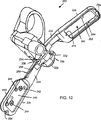
図10〜図12において、末端効果器202はクレビス224を有するジョー組立体218と、クレビス224の周りに、相互に回転し得る第1アーム220、及び第2アーム222と、ハウジング290と、ハウジング290と一体で、内視鏡の端部の周りに(又は、スリットがあれば、その上にスナップ嵌着して)摺動して位置するようにしたスリーブ(連続するスリーブ、又はスリット付き)320とを有する。
10-12, the
ジョー組立体218の第1アーム220は(ファスナー10のおす部材12を収容するようにした)おすジョー226と、ワイヤ状素子を収容するようにした結合孔232を有する対向タング230とを有する。第2アーム222は(ファスナー10のめす部片14を収容するようにした)めすジョー228と、結合孔236を有する対向タング234とを有する。
The
また特に、おすジョー226の内側にはファスナー10のおす部材12の後側を収容するようにした長方形凹所240と、2段貫通孔242、244と、2個のねじ孔248、250とを有する。図3、及び図13に於いて、おす部片12をめすジョー226の凹所240内に挿入し、この凹所内に保持した時、主柱32、34の下部43、45、及び拡大部33、35は段付き貫通孔242、244内に収容される。これにより、主柱32、34を直立状態に保持し、従って、これ等の主柱が倒れた状態に回転するのを防止する。図10、及び図12に戻り、おすジョー226の外側には、ねじ孔248、250に接近できる凹所246と、第1アーム220に延びていて、(以下に説明する釈放素子を支持する)軌道258に連通する出口開口252とを有する。また、おすジョー226の端部にはその機能を以下に説明する溝254を設ける。
In particular, a
第1釈放素子259はクレビス224のハウジング290から、第1アーム220の軌道258内に、出口開口252を通して延在している。第1釈放素子259はファスナーのおす部片の主柱32、34の下端43、45の孔46、48(図3参照)内にそれぞれ挿入される2個のU字状部261、263を画成する分割部分である操作端255を有する。ねじ孔248、250内に挿入されたねじ271、273によって、U字状部261、263上に摩擦板265、267を保持し、U字状部が孔46、48内から、不随意に抜け出すのを防止する摩擦抵抗を提供している。
The
図11〜図13において、めすジョー228はファスナー10のめす部片14のラッチ摺動カバー74、及びカバー部56を収容する寸法を有する比較的大きい、ほぼ長方形の開口260を有する。また、ジョー228は突条275(図16参照)、及び2個の止め金262、264を画成しており、これ等止め金は開口260内に突出している。めす部片14はジョー228内に、ロック位置に挿入され、次にアンロック位置に動かされ、その結果、ラッチ摺動体70(図5参照)のヘッド76が突条275の上にあり、止め金262、264がセットバック部112(図5参照)内に延在し、めす部片14をジョー228内にロックする。めすジョー228の終端に、組織挿通主柱256を設ける。図14、及び図15において、めすジョー226、及びおすジョー228がファスナーのおす部片12、めす部片14から離れていて、互いに密接している時(例えば、ファスナーが釈放されていて、機器が後退している間)、主柱256はおすジョー226の溝254内に位置しており、患者から機器を除去するのを助けるような一層、先細の形態となる。
11-13, the
図15、及び図16において、捩りばね266をめすジョー228に結合し、ファスナー10のめす部片14を強制的にめすジョーの終端に向け押圧する。このことは、ジョー226、228が相互に接近するように弧状に回転する際、おす部片12とめす部片14とが一線になるのを助けるように作用する。更に、ばね266は開口260内に、めす部片14が動くのを許容し、ファスナーのおす部片とめす部片との間にある組織の量に起因する配列の狂いに、応じることができるようにする。図16、及び図17において、また、めすジョー228はアーム222の側部に沿って、延びるワイヤ軌道270のための出口開口268を有する。第2釈放素子272は以下に説明するように、軌道270内に、ハウジング290から出口開口268を通じて延在する。
15 and 16, the
図18において、また、クレビス224は取付け部280を有し、この取付け部において、制御軸206(図9参照)を機器200の末端効果器202に取り付ける。取付け部280は枢着部284で、クレビス224に結合されたブラケット282を有する。また、クレビス224は機械組立体292のためのハウジング290を画成しており、この機械組立体は制御素子208、210上の入力を末端効果器202に伝え、ジョーアーム220、222を動かし、ファスナー10のロック、及び釈放を行う。
In FIG. 18, the
また特に、機械組立体292はハウジングと一体に形成するのが好適な枢着部296の周りに回転自在に結合された第1ベルクランク294を有するのが好適である。制御素子208の末端298を第1ベルクランク294に、その入力側で結合し、V字状ワイヤ300をベルクランクに、その出力側で取り付ける。V字状ワイヤ300は2個のジョーアーム220、222の両方のタング230、234の結合孔232、236(図12参照)に向け延び、この結合孔に連結されている。代案として、ベルクランクの出力側から、2個のタングまで延びる2個の別個のワイヤを使用することができる。図18、及び図19において、制御素子208を制御軸に対し、この医療機器を取り扱う操作者から遠い方向に動かす時、第1ベルクランク294を回転し、V字状ワイヤ300をジョーから離れるように引っ張り、これにより、ジョー226、228を閉止位置に回転する。なお、図18、及び図19において、ジョー226、228を強制的に、完全に閉止位置に動かした時、制御素子208に付加的な力を加えることによって、枢着部284の周りに、取付け部280を回転させ、ジョー226、228を制御軸206に一層近くなるように動かす。これにより、末端効果器の輪郭を減少させ、ファスナー10を機器200から取り外した後、機器を胃、及び食道から取り外すのを助ける。制御素子208を制御軸206に対し、操作者側に動かす時、第1ベルクランク294を回転させて、V字状ワイヤ300によって、強制的にジョー226、228を開放位置に回転させる。更に、図18において、ジョー226、228が完全開放位置にある時、制御素子208に加わる付加的力により、取付け部280を枢着部284の周りに回転させ、これにより、ジョー組立体218を制御軸206から離れるように押圧する。これにより、ジョー組立体218と、制御軸206との間に付加的空間を生ぜしめ、ジョー226、228間の組織を捕捉するのを容易にする。
More particularly, the
図18、及び図19において、また機械組立体292はハウジング290に一体に形成されるのが好適な枢着部304の周りに回転可能に結合された第2ベルクランク302を有する。制御素子210の末端306を第2ベルクランク302の一側に取り付ける。第2ベルクランク302の反対側は押棒310を画成している。ハウジング290内で終わる釈放素子259、272(図17参照)の端部は曲げるか、又はそうでなければ角度をなすように形成して、接触部312、314(図18、及び図19参照)を画成し、ジョーアーム220、222が閉止位置にある時(図19参照)、接触部312、314が押棒310の方向に対して、ほぼ垂直に指向するようにする。
18 and 19, and the
図19、及び図20において、ジョーが閉止位置にあって、制御素子210を制御軸206に対し、操作者から離れる方向に押圧し、第2ベルクランク302に押圧力を加える時、押棒310を強制的に接触部312、314に押し付けて、釈放素子259、272(図16参照)をそれぞれのジョー226、228内に動かす。これにより、ファスナー10のおす部片12、めす部片14を合体ロックし、次のように、ファスナー10をジョー226、228から釈放する。第1に、釈放素子272の端部を摺動組立体52に押し付ける時、摺動組立体はラッチ体50に対し、強制的に、相対的に動かされる。これにより、主柱32、34に対し、ラッチロック72の面取り止め96、98をロックし、これによりファスナーのおす部片12、及びめす部材14を合体ロックする。第2に、摺動組立体の移動によって、摺動カバー74を動かして、ラッチ摺動体のヘッド部76を突条275から釈放し、めすジョー228の止め金262、264を、(スペース108(図6参照)を止め金262、264に一線に配列している)セットバック部112から釈放し、これによりめす部片14をめすジョー228から釈放する。第3に、二又の釈放素子255のU字状端部261、263(図10参照)を主柱32、34の孔46、48の外に動かし、おす部片12をおすジョー226から釈放する。釈放素子255に加わる力は板265、267によって生ずる摩擦に打ち勝つのに十分である。
19 and 20, when the jaw is in the closed position and the
閉じたジョー226、228の間に大量の組織があるか、少量の組織があるか、更に、ジョーをどの程度、閉じるかに基づいて、釈放素子の接触部312、314を押棒310に対して、異なるように設置したいので、押棒310を釈放素子259、272から取り外すことに、注目すべきである。この切り離された調整機構は、正確に閉じたジョーの形態とは関係なく、釈放素子に適切な量の移動を達成させるように作動する。。
Based on whether there is a large amount of tissue between the
代案として、制御素子208を張力の作用下に置いて、ジョーを閉じ、制御素子210を圧縮力の作用下に置いて、ファスナーの部片をロックし、ファスナーをジョーから釈放するように制御素子210を作用させるベルクランクシステムを使用せず、それぞれ、制御素子208、210をジョー226、228に結合し、素子259、272を釈放するのに、他のシステムを使用してもよい。例えば、各制御素子にU字状の端部を設け、この制御素子の端部によって、反対方向に延び、制御素子の残りの部分と同軸ではないが、残りの部分に平行な復帰部を画成する。例えば、制御素子208のU字状端部はジョーに結合することができ、制御素子を圧縮状態にした時、U字状の復帰部はジョーを引っ張って、閉じさせる。同様に、制御素子210のU字状端部を釈放素子259、272に作用する形態にし、制御素子を張力が作用する状態にして、U字状部を釈放素子259、272に押圧する。他の機構も同様に使用することができる。
Alternatively, the
図10、及び図11に戻り、末端効果器218のスリーブ320は比較的小さな内視鏡の直径に対応する約9mmの直径の開口321を有するのが好適である。スリーブ320の外部の寸法は患者の気管食道の通路に末端効果器218が通り易くなるようにできるだけ輪郭が小さくなるように最小にする。また、スリーブ320には斜めの先端を設け、又はその他の先細の形状にし、又はそうでなければ流線の形状にし、気管食道に末端効果器202を導入し、後退させるのを容易にする。更に、スリーブ320は柔らかく、低摩擦で、滑らかな材料、例えばポリテトラフルオロエチレン(PTFE)、ナイロン、又はシリコンのような材料で構成するのが好適であり、内視鏡上に動かすのを助け、人体が損傷するのを防止する。スリーブ320をハウジング290上に結合し、機械組立体292を収容する(図18参照)。スリーブ320を末端効果器202に結合するのを容易にするため、スリーブ320に2個の孔322、324を設けるのが好適であり、第1、及び第2のベルクランク294、302のための枢着部296、及び304(図18参照)にめねじ(図18参照)を設けるのが好適である。ねじ326、328を孔322、324に挿入して、枢着部296、304内にねじ込み、スリーブをハウジング290にロックする。
Returning to FIGS. 10 and 11, the
図9、及び図21において、一実施例に従って、ピストルのグリップ部の形のハンドルである基端操作ハンドル204は固定ハンドル340と、この固定ハンドルに対し、相対的に回転できるレバー342とを有する。固定ハンドル340はハウジング344に一体であり、ハウジング344は縦溝孔346を画成している。制御軸206の基端356をハウジング344内に延長し、レバー342の上部に結合する。第1ベルクランク294を通じて、末端298をジョーアーム220、222に結合した第1制御素子208は基端358を有し、この基端358は制御軸206の基端356の外に突出していて、ハウジング344内の第2取付け部360に固着されている。第2ベルクランク302を通じて、ファスナー10をロックし、釈放するように作動する第2制御素子210は縦溝孔346内で移動し得るクロス棒364に結合された基端362を有する。クロス棒364はハウジング344の外側にあるハンドル部365(図9参照)を有する。レバー342は第1ばね350によって開放位置に押圧されており、このレバー342上のレバー取付け部352と、ハウジング344内の第1取付け部354との間に、第1ばね350は結合されている。また、レバー342にロックシステム366を設け、このロックシステムは、ハンドル340に対して相対的なレバーの位置をロックするように作用する。ロックシステム366はレバー上の複数個の歯368と、枢着部372に取り付けられて、第2ばね374によって歯368の方に押圧される爪370と、外部ノブ378(図9参照)によって手動で回転することができ、回転して爪370に接触し、爪を歯368から離脱させるカム376とを有する。
9 and 21, in accordance with one embodiment, a
作動に当たり、ハンドルレバー342を固定ハンドル340に向け回転した時、制御軸206を第1制御素子208に対し、相対的に末端方向に、即ち、操作者から離れるように動かし、ジョー226、228を閉じる。ジョーが閉止位置にある場合、第2ベルクランク302を作動させて(制御素子210を介して)、ファスナー10をロックし、また、釈放するため、クロス棒364を固定ハンドル340に対し、相対的に末端方向に動かすことができる。ファスナー10を釈放した後、カム376を作用させて、ハンドルロックシステム366を釈放することができ、ハンドルレバー342を固定ハンドル340に対し、相対的に回転することができ、これにより、ジョーを再び開く。
In operation, when the
機器200を作動させるように、ハンドル340のピストルグリップの実施例を示したが、このようなハンドルには顕著な機械的利点があるので、このような望ましい機械的利点を生ずるインライン形ハンドル、又は他のハンドルをも使用するのが好適である。
While an embodiment of a pistol grip for
機器200は一般に、ハンドルを操作することによって、末端効果器を指向させるための大きな能力を有し、大きなトルクを発揮することができる。即ち、機器200は特にその長さが少なくとも約150cm、それどころか、190cm以上の長さがあり、捩じりに対し、剛強な可撓性軸を有する。このトルク能力によって、約180°に過ぎない角度が好適なハンドルの回転を通じて、末端効果器組立体212を(目標の組織に向けいくらでも接近するため)180°にわたり回転させる。このことは、ハンドル340に固着されて、回転する制御素子208によって、或る程度、容易になる。制御素子208は直径が比較的大きく、約0.9 mm(0.035 インチ)の不銹鋼が最も好適である。約0.5 mm(0.020 インチ)と1.6 mm(0.062 インチ)との間の直径が好適な同様の溝のワイヤも適切である。
The
本発明の方法の一実施例によれば、胃食道逆流疾患(GERD)に関して、次のように、機器200を作動させることができる。図22において、末端効果器202のスリーブ320を内視鏡400の末端上に摺動するように結合し、末端効果器を内視鏡上に、基端側に、即ち操作者側に摺動させる。次にこの内視鏡400の末端を気管食道内に挿入し、食道を通して動かし、好適には内視鏡400の末端から、基端側に約20cmの位置に末端効果器を取り付けた状態で、機器200のを胃の中に入れる。次に、ハンドル204、及び/又は制御軸206を全体的に操作して、挿入された内視鏡400の末端上に、末端効果器202を摺動させて、スリーブ320のための案内ワイヤとして機能する内視鏡400と共に、末端効果器を胃の中に入れる。場合により、食道の下部食道括約筋(LES)402の方に振り向いて、末端効果器202の前進が見えるように、内視鏡400をそり返るものにしてもよい。
According to one embodiment of the method of the present invention, the
図23Aにおいて、内視鏡上の末端効果器を患者の身体に挿入し(そして、後に患者から、末端効果器を後退させ)ている間、このシステムの最大の横断面積が食道内に延在することが発生するが、その横断面積はスリーブ320の区域と、スリーブの専有面積の外側に伸びるクレビス224の部分とであって、現存する従来の提案されたいかなる装置よりも狭い約188mm2 である。食道内でのこのシステムの2番目に大きい横断面積はファスナー10が装填されたジョー226、228の位置である。図23Bにおいて、この面積にはファスナーが装填されたジョー組立体218、制御軸206、及び内視鏡400の専有面積であって、約178mm2 である。図23A、及び図23Bの横断面積を有するシステムの部分は患者の身体に末端効果器を挿入し、除去している間だけ、食道内にある。図24において、これ以外の、全ての時間に、本システムの基端から末端効果器までの他の全ての部分に沿う、食道内のシステムの横断面積は内視鏡400の横断面積(9mm内視鏡で、約63.6mm2 )と、制御軸206の横断面積(4mm制御軸で、約12.6mm2 )との結合された横断面積にほぼ限定され、これより少なく、即ち全横断面積で76.2mm2 、又はそれ以下である。
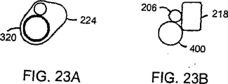
In FIG. 23A, the maximum cross-sectional area of the system extends into the esophagus while the end effector on the endoscope is inserted into the patient's body (and later retracted from the patient). The cross-sectional area of the
これに対して、従来技術の図25はこの明細書の背景技術で説明したNDO装置のような18mm直径(254mm2 )を有する従来の装置900に相当している横断面積の相対寸法を示している。この比較的大きな面積は操作の手順を行う期間を通じて、食道を詰まらせる。
In contrast, prior art FIG. 25 shows the relative dimensions of the cross-sectional area corresponding to a
末端効果器202の挿入中、内視鏡が湾曲して、そり返ると、末端効果器の胃への通過は内視鏡400で見ながら行われる。末端効果器が一旦、胃の中に位置すると、内視鏡は湾曲していたとすれば、真っ直ぐになるのが好ましく、末端効果器は内視鏡から離れて、末端側に動き、内視鏡400と、機器200とは完全に分離する。図26において、次に、内視鏡400は再び湾曲し、そり返り、上に述べたように、機器ハンドル204を操作すれば、末端効果器202のジョー226、228を開く。
If the endoscope bends and turns during insertion of the
図27において、例えば、鉗子、ヘリカルニードル、タッピング装置のような組織把持機器406を内視鏡400の作業チャネル408を通じて、挿入するのが好適であり、ひだの中心が位置しているはずのLES(下部食道括約筋)に隣接して胃の中に1〜3センチの位置の目標組織410に、組織把持器を指向させる。把持機器406は組織410に掛合し、機器200の末端効果器202のジョー226、228間に組織を引っ張る。更に、機器200のハンドル204、及び/又は制御軸206を全体として、戻るように引っ張り(即ち、機器を後退させる方向に引っ張り)、食道にほぼ平行な方向に、ジョーが組織410に接近するようにする。これは内視鏡のGERD治療器具では、今まで達成できなかった接近のための望ましい角度である。即ち、湾曲する、即ちそり返るいかなる装置も弓形に延在しなければならない。湾曲した装置は入口路に平行になることと、入口路から離れて、2cm移動することの両方が不可能である。
In FIG. 27, a
次に、基端操作ハンドル204を操作して、ジョー226、228を閉じる。ジョーの移動中、組織410の中心点は組織把持機器406によって、ジョーの間の固定位置に、保持されるから、組織のひだ412がジョーによって、形成されているとすれば、ファスナー10のおす部片12と、めす部片14とは両者間にクランプされたひだ412に合体する。ジョー226、228が組織のひだ412の周りに閉じた時、ファスナーのおす部片12の主柱32、34は奨膜まで、この組織に挿通するのが好適であり、めすジョー228の挿通主柱256が組織の深い位置の筋に挿通し、組織を十分に損傷させ、奨膜と奨膜とを接触させるのが好適である。実験を行った結果、この接触によって、治療後、組織の癒着を生ずる。即ち、ファスナー10を後に除去しても、組織は恒久的に再構成されることがわかった。このようにして、LESの周りに、減少した整合性の帯域が発生する。
Next, the proximal end operation handle 204 is operated to close the
ひだの位置、及び寸法、及びファスナーの部片の相対位置は内視鏡を通じて、観察される。更に、基端操作ハンドル204の制御によって、一層高い、又は一層低いクランプ圧力をひだが付いた組織に加えることができる。
The position and size of the pleats and the relative position of the fastener pieces are observed through the endoscope. In addition, higher or lower clamping pressure can be applied to the pleated tissue by control of the
図29において、ひだ412が満足に現れていれば、そこで、上述したように、基端操作ハンドル204を操作し、ファスナー10のおす部片12、めす部片14をロックし、結合されたファスナーをジョー226、228から釈放する。もしも、ひだ、又はファスナー位置が満足でなければ、ロック、及び釈放の前に、ジョーを開くことができ、必要ならば、新しい方向を与え、他のひだを形成することができる。
In FIG. 29, if the
ファスナーを加えた後、次にジョーを閉じ、内視鏡を真っ直ぐにし、内視鏡の末端上に、末端効果器を再結合させるのが好適である。食道を通じて、患者の外に、機器と、内視鏡とを共に引き出すのが好適である。代案として、最初に、内視鏡を引き出し、次に、目に見える状態が好適であるが、機器を引き出す。 After the fasteners have been added, it is then preferable to close the jaws, straighten the endoscope, and reconnect the end effector onto the distal end of the endoscope. It is preferable to draw both the device and the endoscope out of the patient through the esophagus. As an alternative, first pull out the endoscope, then pull out the device, although a visible condition is preferred.
上述したように、移植の手順の間に、又はその手順の後の或る時に、ファスナー、又はファスナーの部片のいずれかが緩んだ場合は、ファスナーの素子の鋭利な部分を安全な形態になるようにするか、又は恒久的に覆うようにする。従って、ファスナー、又はその部片を患者の胃腸系を通じて、安全に通すことができる。 As noted above, if either the fastener, or a piece of the fastener, loosens during the implantation procedure or at some time after the procedure, the sharpened portion of the fastener element is put into a safe form. Or be permanently covered. Thus, the fastener, or part thereof, can be safely passed through the patient's gastrointestinal system.
手順を行っている間、内視鏡から機器を取り外すのが好適であるが、内視鏡に結合している間に、機器を操作するのがよい。即ち図30において、ジョー226、228を開くことによって、また、内視鏡400に沿って、機器200を単に後退させることによって、目標組織に接近し、LESの周りの組織に接触する。上述したように、ジョー226、228を閉じ、ファスナー10を加える。この手順を利用するため、機器のスリーブ320をジョー226、228に対し、相対的にずらすべきであり、これにより、開閉する時、ジョーを内視鏡から、離すことができる。
While performing the procedure, it is preferred to remove the device from the endoscope, but it is better to operate the device while coupled to the endoscope. That is, in FIG. 30, by opening the
図31、及び図32に、本発明による機器200の末端効果器502の第1の代案の実施例を示す。内視鏡の周りにスリーブを結合するのでなく、内視鏡の作用チャネルの末端内に、末端効果器502を結合し得るようにする。この目的のため、末端効果器502のハウジング590に、上方に位置するのが好適であるが、制御軸206に一線に、基端に指向するペグ620を設ける。このペグ620を内視鏡の作用チャネルの末端内に、収容される大きさにする。更に、ハウジング590に、凹形表面622を設け、この凹形表面622によって、ハウジング590と、内視鏡とを最小の輪郭内に隣接させ得るようにする。
31 and 32 show a first alternative embodiment of the
使用に当たり、ペグ620を使用して、末端効果器を内視鏡の末端に連結し、制御軸206を内視鏡に対して、保持し、結合を維持する。末端効果器でのこのシステムの横断面積(末端効果器と内視鏡とは互いに結合されている)は約150mm2 である。内視鏡を末端効果器に密接嵌着し、スリーブの寸法を無いものにすれば、このシステムの横断面積はスリーブを利用しているシステムによって画成される横断面積より小さいことに注意すべきである。次に、末端に、末端効果器502を取り付けた内視鏡を患者の胃の中に挿入する。次に基端ハンドル204、及び/又は制御軸206を全体的に操作して、末端効果器を外す。その後、上述したようにするのが好適であるが、手順を継続し、ひだとファスナーとの適用を達成する。次に、機器と内視鏡とを除去する前に、末端効果器502を内視鏡に再連結し、機器と内視鏡とを患者から引き出す。代案として、内視鏡と機器とを別々に除去してもよい。
In use, the
機器を内視鏡に連結するように示したが、機器を内視鏡から常に外しているように使用するため、機器を変更してもよい。図33、及び図34に、代わりの第2実施としての機器200の末端効果器702を示す。末端効果器702のハウジング790には案内ワイヤ824を収容する寸法の縦通路822を画成している先細ノーズピース820を設ける。この案内ワイヤは1mm以下の直径を有していてもよい。ノーズピース820はシリコンのような非常に可撓性の材料で形成するのが好適である。
Although the device has been shown to be coupled to an endoscope, the device may be modified in order to use the device so that it is always removed from the endoscope. 33 and 34 show an
図35を参照し、好適な使用方法により、気管食道路414を通じて、よく知られた手順により、胃416内に、内視鏡400をまず挿入するのが好適である。次に、図36において、内視鏡を通じて、案内ワイヤ924を胃の中に前進させる。次に、図37において、内視鏡400を案内ワイヤ824から、引き出すのが好適である。図38において、次に、末端効果器702を案内ワイヤ924上に、手探りで前進させ、胃416内に導入する。先細ノーズピース820と、システムの比較的小さな先端の横断面積によって、この導入は容易になる。図39において、末端効果器702を胃716内に設置した後、案内ワイヤ824を胃から引き出すのが好適である。次に、図40、及び図41において、機器の制御軸に平行して、内視鏡を導入し、胃の中に前進させ、末端効果器702を見るため、湾曲させ、即ち、そり返らせる。末端効果器702のジョー726、728も開いていて、ひだを付けるべき組織に隣接させる。図42において、内視鏡400の作用チャネルを通じて、組織把持装置920を展開し、ひだを折るのが望ましい位置で、組織910に掛合するように、組織把持機器920を作動させる。この組織把持装置は粘膜、及び筋層(深筋)に貫通する挿通器を有するのが好適であり、これによりこれ等の層を合体保持し、層間剥離を防止する。図43において、末端効果器702のジョーを閉じ、掛合した組織910の周りにひだ812を形成し、このひだは食道にほぼ平行である。このひだは組織把持機器920によって保持された位置から、機器のジョーの端部まで延びる。図44において、ファスナー10を展開し、末端効果器702のジョーを開く。図45において、末端効果器702のジョーを閉じ、内視鏡400によって、見える状態で、食道414を通じて、末端効果器702を引き出す。即ち、末端効果器702の閉じたジョーを内視鏡400の末端に直接位置させるのが好適であり、内視鏡、及び機器システムの横断面積を最小にすると共に、食道を通じて、末端効果器を後退させている間、末端効果器を常に見得るようにする。
With reference to FIG. 35, it is preferred to first insert the
この実施例は食道内のシステムの横断面積を最小にすることができ、これは、(1)末端効果器の面積を限定するか、又は(2)内視鏡、及び制御軸の面積を限定するからである。但し、(1)、及び(2)を同時には行わない。図46において、(1)に関し、ジョー組立体の末端で、クレビス790を横切る末端効果器の横断面積は約75mm2 である。また、(1)に関し、クレビスの基端側で、ジョー組立体718を横切る末端効果器の横断面積は(ジョー組立体が閉止位置にあって)約115mm2 (ジョー組立体718の横断面積の約102mm2 と、4mmの制御軸の横断面積の12.6mm2 との和として計算された)である。(2)に関しては、9mm内視鏡の63.6mm2と、4mmの制御軸の12.6mm2 との和として計算される内視鏡、及び制御軸の合計の横断面積は76.2mm2 である。
This embodiment can minimize the cross-sectional area of the system in the esophagus, which either (1) limits the area of the end effector or (2) limits the area of the endoscope and control axis. Because it does. However, (1) and (2) are not performed simultaneously. In FIG. 46, with respect to (1), the end effector cross-sectional area across the
胃と食道の逆流性疾病、即ち胃食道逆流疾患(GERD)の内腔治療のためのファスナー、機器、システム、及び方法の数個の実施例を説明し、図示した。本発明の特定の実施例を説明したが、本発明はこれ等の実施例に限定されず、本発明の範囲内で種々の変更を加えることができる。例えば、機器、及びファスナーの両方の素子について特に好適な寸法、及びシステムの横断面積を提供したが、システム、及びその素子は異なる相対寸法を有していてもよい。例えば、もし小児科の内視鏡(4〜6mm)を使用するならば、この横断面積を一層、減少させることができる。また、「ルッキングバック(振り返って後方を見る)」機器を特に、胃食道逆流疾患を治療するように設計したファスナーの適用に関し開示したが、例えば肥満症、潰瘍、胃癌、pH測定装置、又はpH監視装置の移植、栄養チューブの移植等のその他の状態を処置するため、ファスナーを加えるように、同様のジョー組立体を有する「フォワードルッキング(前方を見る)」真っ直ぐな機器を使用することもできることは明らかである。更に、真っ直ぐな装置の直径を一層小さくすることができ、内視鏡の作用チャネルを通じて操作することができる。従って、本発明は特許請求の範囲内において、種々の変更を加えることができることは明らかである。 Several examples of fasteners, devices, systems, and methods for the lumen treatment of gastroesophageal reflux disease, or gastroesophageal reflux disease (GERD), have been described and illustrated. Although specific embodiments of the present invention have been described, the present invention is not limited to these embodiments, and various modifications can be made within the scope of the present invention. For example, although particularly preferred dimensions and cross-sectional areas of the system have been provided for both device and fastener elements, the system and its elements may have different relative dimensions. For example, if a pediatric endoscope (4-6 mm) is used, this cross-sectional area can be further reduced. Also, a “Looking Back” device has been disclosed, particularly with respect to the application of fasteners designed to treat gastroesophageal reflux disease, eg, obesity, ulcer, stomach cancer, pH measuring device, or pH A “forward-looking” straight device with a similar jaw assembly can be used to add fasteners to treat other conditions such as monitoring device implantation, feeding tube implantation, etc. Is clear. Furthermore, the diameter of the straight device can be further reduced and can be operated through the working channel of the endoscope. Therefore, it is obvious that the present invention can be variously modified within the scope of the claims.
Claims (26)
b)前記少なくとも1個の剛強な直立する組織挿通主柱のそれぞれを収容する孔を画成する第2ベースと、第1形態と第2形態との間に、前記第2ベースに対し、相対的に移動することができる可動部とを有する第2部片とを具え、
前記可動部が前記第1形態にあって、前記少なくとも1個の剛強な直立する主柱がそれぞれの孔に挿入されている時、前記可動部が前記第2形態に移動することによって、前記第2部片に対し、前記第1部片をロックすることを特徴とする外科用ファスナー。 a) a first piece having a first base provided with at least one rigid upright tissue insertion main post;
b) relative to the second base between the first base and the second form, the second base defining a hole for accommodating each of the at least one rigid and upright tissue insertion main pillar; A second piece having a movable part that can be moved in an automatic manner,
When the movable part is in the first form, and the at least one rigid upright main pillar is inserted into each hole, the movable part moves to the second form, thereby A surgical fastener, wherein the first piece is locked to two pieces.
前記少なくとも1個の主柱がそれぞれの孔を通じて、前記ベース内に収容されている時、しかも前記第2ベースと、前記可動部とが前記第2形態にある時、前記第1カバー部、及び前記第2カバー部が前記少なくとも1個の主柱の前記先端部を遮蔽している請求項1による外科用ファスナー。 Each of the at least one main pillar has a tip portion, the movable portion has a first cover portion, and the second base has a second cover portion,
When the at least one main pillar is accommodated in the base through the respective holes, and when the second base and the movable part are in the second form, the first cover part, and The surgical fastener according to claim 1, wherein the second cover portion shields the distal end portion of the at least one main pillar.
b)前記少なくとも1個の主柱を収容することができ、前記第1部片に対し、機械的にロックされる第2部片とを具えることを特徴とする外科用ファスナー。 a) a first piece having a base and provided with at least one rigid tissue insertion main column on the base that is rotatable relative to the base about a respective axis;
b) A surgical fastener characterized in that it can accommodate the at least one main column and has a second piece that is mechanically locked to the first piece.
b)前記少なくとも1個の剛強主柱を収容するようにした少なくとも1個の開口を有するベースと、遮蔽部とを有し、前記第1部片に対し、機械的にロックされるようにした第2部片とを具え、
前記第1部片と前記第2部片とを互いに相対的にロックした時、前記少なくとも1個の剛強主柱が前記ベースの前記少なくとも1個の開口に貫通し、前記遮蔽部が前記組織挿通先端部を遮蔽することを特徴とする外科用ファスナー。 a) a first piece having a base provided with at least one rigid main column having a tissue insertion tip;
b) a base having at least one opening adapted to receive the at least one rigid main column and a shielding portion, and mechanically locked to the first piece; With a second part,
When the first piece and the second piece are locked relative to each other, the at least one rigid main pillar penetrates the at least one opening of the base, and the shielding portion passes through the tissue. A surgical fastener characterized by shielding a tip portion.
b)前記少なくとも1個の主柱を収容するようにした少なくとも1個の開口を有するベースと、前記少なくとも1個の主柱のそれぞれの前記掛合構造の1個に掛合するようにした止め金構造とを有する第2部片とを具え、この掛合によって、前記第1部片と前記第2部片とを互いにロックする外科用ファスナー。 a) a first piece having a base with at least one main post having a tissue insertion tip and defining a plurality of longitudinally offset engagement structures;
b) a base having at least one opening adapted to receive the at least one main pillar, and a clasp structure adapted to be engaged with one of the engaging structures of each of the at least one main pillar. A surgical fastener that locks the first piece and the second piece together by engaging with the second piece.
b)前記少なくとも1個の主柱を収容するようにした開口を有する第2ベースを有する第2部片と、
c)前記第1ベースと前記第2ベースとが相互に平行であるか、傾いているかに関係なく、前記第1部片と前記第2部片とを機械的にロックする手段とを具えることを特徴とする外科用ファスナー。 a) a first piece having a first base provided with at least one tissue insertion main pillar;
b) a second piece having a second base with an opening adapted to receive said at least one main pillar;
c) means for mechanically locking the first piece and the second piece regardless of whether the first base and the second base are parallel to each other or inclined; Surgical fastener characterized by that.
b)前記少なくとも1個の主柱を収容するようにした開口を有する第2ベースを有する第2部片と、
c)前記第1ベースと前記第2ベースとが相互に相対的に、数回、移動する度に、前記第1部片、及び前記第2部片を機械的にロックする手段とを具えることを特徴とする外科用ファスナー。 a) a first piece having a first base provided with at least one tissue insertion main pillar;
b) a second piece having a second base with an opening adapted to receive said at least one main pillar;
c) comprising means for mechanically locking the first piece and the second piece each time the first base and the second base move relative to each other several times; Surgical fastener characterized by that.
b)チタン、又はチタン合金で構成された第2部片とを具え、前記第1部片、及び前記第2部片を機械的にロックするようにした協働構造を前記第1部片、及び前記第2部片に設け、
前記第1部片、及び前記第2部片を陽極酸化させたことを特徴とする外科用ファスナー。 a) a first piece made of titanium or a titanium alloy;
b) a second part piece made of titanium or a titanium alloy, wherein the first part and the second part piece mechanically lock the first part piece, And provided on the second piece,
A surgical fastener, wherein the first piece and the second piece are anodized.
Applications Claiming Priority (2)
| Application Number | Priority Date | Filing Date | Title |
|---|---|---|---|
| US10/252,079 US7033378B2 (en) | 2002-09-20 | 2002-09-20 | Surgical fastener, particularly for the endoluminal treatment of gastroesophageal reflux disease (GERD) |
| PCT/US2003/029523 WO2004026349A2 (en) | 2002-09-20 | 2003-09-19 | Surgical fastener particularly for the treatment of gastroesophageal reflux disease (gerd) |
Publications (1)
| Publication Number | Publication Date |
|---|---|
| JP2006500112A true JP2006500112A (en) | 2006-01-05 |
Family
ID=31992876
Family Applications (1)
| Application Number | Title | Priority Date | Filing Date |
|---|---|---|---|
| JP2004538250A Pending JP2006500112A (en) | 2002-09-20 | 2003-09-19 | Surgical fasteners especially for the treatment of gastroesophageal reflux disease |
Country Status (6)
| Country | Link |
|---|---|
| US (1) | US7033378B2 (en) |
| EP (1) | EP1558148A4 (en) |
| JP (1) | JP2006500112A (en) |
| AU (1) | AU2003272576A1 (en) |
| CA (1) | CA2500302C (en) |
| WO (1) | WO2004026349A2 (en) |
Families Citing this family (447)
| Publication number | Priority date | Publication date | Assignee | Title |
|---|---|---|---|---|
| US6663639B1 (en) | 1999-06-22 | 2003-12-16 | Ndo Surgical, Inc. | Methods and devices for tissue reconfiguration |
| US8287554B2 (en) | 1999-06-22 | 2012-10-16 | Ethicon Endo-Surgery, Inc. | Method and devices for tissue reconfiguration |
| US6835200B2 (en) * | 1999-06-22 | 2004-12-28 | Ndo Surgical. Inc. | Method and devices for tissue reconfiguration |
| US6821285B2 (en) | 1999-06-22 | 2004-11-23 | Ndo Surgical, Inc. | Tissue reconfiguration |
| US7846180B2 (en) * | 1999-06-22 | 2010-12-07 | Ethicon Endo-Surgery, Inc. | Tissue fixation devices and methods of fixing tissue |
| US7033373B2 (en) | 2000-11-03 | 2006-04-25 | Satiety, Inc. | Method and device for use in minimally invasive placement of space-occupying intragastric devices |
| US6558400B2 (en) | 2001-05-30 | 2003-05-06 | Satiety, Inc. | Obesity treatment tools and methods |
| US7083629B2 (en) * | 2001-05-30 | 2006-08-01 | Satiety, Inc. | Overtube apparatus for insertion into a body |
| US6773440B2 (en) * | 2002-07-02 | 2004-08-10 | Satiety, Inc. | Method and device for use in tissue approximation and fixation |
| US6746460B2 (en) * | 2002-08-07 | 2004-06-08 | Satiety, Inc. | Intra-gastric fastening devices |
| US7033384B2 (en) | 2002-08-30 | 2006-04-25 | Satiety, Inc. | Stented anchoring of gastric space-occupying devices |
| US7214233B2 (en) * | 2002-08-30 | 2007-05-08 | Satiety, Inc. | Methods and devices for maintaining a space occupying device in a relatively fixed location within a stomach |
| US8454628B2 (en) * | 2002-09-20 | 2013-06-04 | Syntheon, Llc | Surgical fastener aligning instrument particularly for transoral treatment of gastroesophageal reflux disease |
| US7678122B2 (en) * | 2002-09-20 | 2010-03-16 | Id, Llc | Method of performing a treatment for gastroesophagheal reflux disease (GERD) |
| US7220237B2 (en) * | 2002-10-23 | 2007-05-22 | Satiety, Inc. | Method and device for use in endoscopic organ procedures |
| US7229428B2 (en) * | 2002-10-23 | 2007-06-12 | Satiety, Inc. | Method and device for use in endoscopic organ procedures |
| US9060844B2 (en) | 2002-11-01 | 2015-06-23 | Valentx, Inc. | Apparatus and methods for treatment of morbid obesity |
| US7794447B2 (en) * | 2002-11-01 | 2010-09-14 | Valentx, Inc. | Gastrointestinal sleeve device and methods for treatment of morbid obesity |
| US8070743B2 (en) * | 2002-11-01 | 2011-12-06 | Valentx, Inc. | Devices and methods for attaching an endolumenal gastrointestinal implant |
| US20060015125A1 (en) * | 2004-05-07 | 2006-01-19 | Paul Swain | Devices and methods for gastric surgery |
| US7837669B2 (en) * | 2002-11-01 | 2010-11-23 | Valentx, Inc. | Devices and methods for endolumenal gastrointestinal bypass |
| US6656194B1 (en) * | 2002-11-05 | 2003-12-02 | Satiety, Inc. | Magnetic anchoring devices |
| US7175638B2 (en) | 2003-04-16 | 2007-02-13 | Satiety, Inc. | Method and devices for modifying the function of a body organ |
| US20070084897A1 (en) | 2003-05-20 | 2007-04-19 | Shelton Frederick E Iv | Articulating surgical stapling instrument incorporating a two-piece e-beam firing mechanism |
| US9060770B2 (en) | 2003-05-20 | 2015-06-23 | Ethicon Endo-Surgery, Inc. | Robotically-driven surgical instrument with E-beam driver |
| US7914543B2 (en) * | 2003-10-14 | 2011-03-29 | Satiety, Inc. | Single fold device for tissue fixation |
| US7097650B2 (en) * | 2003-10-14 | 2006-08-29 | Satiety, Inc. | System for tissue approximation and fixation |
| US6960218B2 (en) * | 2003-10-20 | 2005-11-01 | Henry Rennich | External incontinence clamp |
| US20050241651A1 (en) * | 2003-10-20 | 2005-11-03 | Henry Rennich | External incontinence clamp |
| US7473261B2 (en) * | 2003-10-20 | 2009-01-06 | Henry Rennich | External incontinence clamp |
| US7347863B2 (en) | 2004-05-07 | 2008-03-25 | Usgi Medical, Inc. | Apparatus and methods for manipulating and securing tissue |
| US20050177176A1 (en) * | 2004-02-05 | 2005-08-11 | Craig Gerbi | Single-fold system for tissue approximation and fixation |
| US7379672B2 (en) * | 2004-02-12 | 2008-05-27 | Northrop Grumman Corporation | Photonic RF distribution system |
| US8828025B2 (en) * | 2004-02-13 | 2014-09-09 | Ethicon Endo-Surgery, Inc. | Methods and devices for reducing hollow organ volume |
| AU2005218318A1 (en) * | 2004-02-27 | 2005-09-15 | Ethicon Endo-Surgery, Inc | Methods and devices for reducing hollow organ volume |
| US9028511B2 (en) | 2004-03-09 | 2015-05-12 | Ethicon Endo-Surgery, Inc. | Devices and methods for placement of partitions within a hollow body organ |
| US8252009B2 (en) * | 2004-03-09 | 2012-08-28 | Ethicon Endo-Surgery, Inc. | Devices and methods for placement of partitions within a hollow body organ |
| US8628547B2 (en) | 2004-03-09 | 2014-01-14 | Ethicon Endo-Surgery, Inc. | Devices and methods for placement of partitions within a hollow body organ |
| US8449560B2 (en) | 2004-03-09 | 2013-05-28 | Satiety, Inc. | Devices and methods for placement of partitions within a hollow body organ |
| CA2561193A1 (en) | 2004-03-26 | 2005-10-20 | Satiety, Inc. | Systems and methods for treating obesity |
| US7736374B2 (en) * | 2004-05-07 | 2010-06-15 | Usgi Medical, Inc. | Tissue manipulation and securement system |
| US20060135971A1 (en) * | 2004-05-07 | 2006-06-22 | Usgi Medical Inc. | System for treating gastroesophageal reflux disease |
| US8257394B2 (en) | 2004-05-07 | 2012-09-04 | Usgi Medical, Inc. | Apparatus and methods for positioning and securing anchors |
| US20050251176A1 (en) * | 2004-05-07 | 2005-11-10 | Usgi Medical Inc. | System for treating gastroesophageal reflux disease |
| US11998198B2 (en) | 2004-07-28 | 2024-06-04 | Cilag Gmbh International | Surgical stapling instrument incorporating a two-piece E-beam firing mechanism |
| US9072535B2 (en) | 2011-05-27 | 2015-07-07 | Ethicon Endo-Surgery, Inc. | Surgical stapling instruments with rotatable staple deployment arrangements |
| US8215531B2 (en) | 2004-07-28 | 2012-07-10 | Ethicon Endo-Surgery, Inc. | Surgical stapling instrument having a medical substance dispenser |
| US11890012B2 (en) | 2004-07-28 | 2024-02-06 | Cilag Gmbh International | Staple cartridge comprising cartridge body and attached support |
| US20060106288A1 (en) | 2004-11-17 | 2006-05-18 | Roth Alex T | Remote tissue retraction device |
| US7438208B2 (en) * | 2005-01-25 | 2008-10-21 | Entrigue Surgical, Inc. | Septal stapler apparatus |
| US7691053B2 (en) * | 2005-05-20 | 2010-04-06 | Tyco Healthcare Group Lp | Gastric restrictor assembly and method of use |
| US7669746B2 (en) | 2005-08-31 | 2010-03-02 | Ethicon Endo-Surgery, Inc. | Staple cartridges for forming staples having differing formed staple heights |
| US10159482B2 (en) | 2005-08-31 | 2018-12-25 | Ethicon Llc | Fastener cartridge assembly comprising a fixed anvil and different staple heights |
| US11246590B2 (en) | 2005-08-31 | 2022-02-15 | Cilag Gmbh International | Staple cartridge including staple drivers having different unfired heights |
| US7934630B2 (en) | 2005-08-31 | 2011-05-03 | Ethicon Endo-Surgery, Inc. | Staple cartridges for forming staples having differing formed staple heights |
| US9237891B2 (en) | 2005-08-31 | 2016-01-19 | Ethicon Endo-Surgery, Inc. | Robotically-controlled surgical stapling devices that produce formed staples having different lengths |
| US11484312B2 (en) | 2005-08-31 | 2022-11-01 | Cilag Gmbh International | Staple cartridge comprising a staple driver arrangement |
| US20070106317A1 (en) | 2005-11-09 | 2007-05-10 | Shelton Frederick E Iv | Hydraulically and electrically actuated articulation joints for surgical instruments |
| US8726909B2 (en) | 2006-01-27 | 2014-05-20 | Usgi Medical, Inc. | Methods and apparatus for revision of obesity procedures |
| US20110290856A1 (en) | 2006-01-31 | 2011-12-01 | Ethicon Endo-Surgery, Inc. | Robotically-controlled surgical instrument with force-feedback capabilities |
| US11224427B2 (en) | 2006-01-31 | 2022-01-18 | Cilag Gmbh International | Surgical stapling system including a console and retraction assembly |
| US8820603B2 (en) | 2006-01-31 | 2014-09-02 | Ethicon Endo-Surgery, Inc. | Accessing data stored in a memory of a surgical instrument |
| US11278279B2 (en) | 2006-01-31 | 2022-03-22 | Cilag Gmbh International | Surgical instrument assembly |
| US7753904B2 (en) | 2006-01-31 | 2010-07-13 | Ethicon Endo-Surgery, Inc. | Endoscopic surgical instrument with a handle that can articulate with respect to the shaft |
| US11793518B2 (en) | 2006-01-31 | 2023-10-24 | Cilag Gmbh International | Powered surgical instruments with firing system lockout arrangements |
| US8708213B2 (en) | 2006-01-31 | 2014-04-29 | Ethicon Endo-Surgery, Inc. | Surgical instrument having a feedback system |
| US20120292367A1 (en) | 2006-01-31 | 2012-11-22 | Ethicon Endo-Surgery, Inc. | Robotically-controlled end effector |
| US7845537B2 (en) | 2006-01-31 | 2010-12-07 | Ethicon Endo-Surgery, Inc. | Surgical instrument having recording capabilities |
| US20110024477A1 (en) | 2009-02-06 | 2011-02-03 | Hall Steven G | Driven Surgical Stapler Improvements |
| US8186555B2 (en) | 2006-01-31 | 2012-05-29 | Ethicon Endo-Surgery, Inc. | Motor-driven surgical cutting and fastening instrument with mechanical closure system |
| US8992422B2 (en) | 2006-03-23 | 2015-03-31 | Ethicon Endo-Surgery, Inc. | Robotically-controlled endoscopic accessory channel |
| US7881797B2 (en) * | 2006-04-25 | 2011-02-01 | Valentx, Inc. | Methods and devices for gastrointestinal stimulation |
| EP2015681B1 (en) | 2006-05-03 | 2018-03-28 | Datascope Corp. | Tissue closure device |
| US20070293946A1 (en) * | 2006-05-12 | 2007-12-20 | Entrigue Surgical, Inc. | Middle Turbinate Medializer |
| US8322455B2 (en) | 2006-06-27 | 2012-12-04 | Ethicon Endo-Surgery, Inc. | Manually driven surgical cutting and fastening instrument |
| US20080046008A1 (en) * | 2006-08-21 | 2008-02-21 | Ethicon Endo-Surgery, Inc. | Surgical fastener |
| US20080046007A1 (en) * | 2006-08-21 | 2008-02-21 | Ethicon Endo-Surgery, Inc. | Surgical fastener |
| US10568652B2 (en) | 2006-09-29 | 2020-02-25 | Ethicon Llc | Surgical staples having attached drivers of different heights and stapling instruments for deploying the same |
| US11980366B2 (en) | 2006-10-03 | 2024-05-14 | Cilag Gmbh International | Surgical instrument |
| US8632535B2 (en) | 2007-01-10 | 2014-01-21 | Ethicon Endo-Surgery, Inc. | Interlock and surgical instrument including same |
| US8684253B2 (en) | 2007-01-10 | 2014-04-01 | Ethicon Endo-Surgery, Inc. | Surgical instrument with wireless communication between a control unit of a robotic system and remote sensor |
| US11291441B2 (en) | 2007-01-10 | 2022-04-05 | Cilag Gmbh International | Surgical instrument with wireless communication between control unit and remote sensor |
| US11039836B2 (en) | 2007-01-11 | 2021-06-22 | Cilag Gmbh International | Staple cartridge for use with a surgical stapling instrument |
| US20080169332A1 (en) | 2007-01-11 | 2008-07-17 | Shelton Frederick E | Surgical stapling device with a curved cutting member |
| US20080215090A1 (en) * | 2007-02-14 | 2008-09-04 | Entrigue Surgical, Inc. | Method and System for Tissue Fastening |
| US8727197B2 (en) | 2007-03-15 | 2014-05-20 | Ethicon Endo-Surgery, Inc. | Staple cartridge cavity configuration with cooperative surgical staple |
| US20080228199A1 (en) * | 2007-03-16 | 2008-09-18 | Ethicon Endo-Surgery, Inc. | Endoscopic tissue approximation method |
| US20080228202A1 (en) * | 2007-03-16 | 2008-09-18 | Ethicon Endo-Surgery, Inc. | Endoscopic tissue approximation system |
| US20080234703A1 (en) * | 2007-03-23 | 2008-09-25 | Ethicon Endo-Surgery, Inc. | Tissue approximation system |
| US8852216B2 (en) * | 2007-03-23 | 2014-10-07 | Ethicon Endo-Surgery, Inc. | Tissue approximation methods |
| US8814901B2 (en) * | 2007-05-08 | 2014-08-26 | Ethicon Endo-Surgery, Inc. | Surgical fastener |
| US8052698B2 (en) * | 2007-05-30 | 2011-11-08 | Ethicon Endo-Surgery, Inc. | Surgical instrument |
| US20080300624A1 (en) * | 2007-05-30 | 2008-12-04 | Ethicon Endo-Surgery, Inc. | Tissue Stabilizer and Fastener |
| US7699871B2 (en) * | 2007-05-30 | 2010-04-20 | Ethicon Endo-Surgery, Inc. | Surgical instrument |
| US11857181B2 (en) | 2007-06-04 | 2024-01-02 | Cilag Gmbh International | Robotically-controlled shaft based rotary drive systems for surgical instruments |
| US8931682B2 (en) | 2007-06-04 | 2015-01-13 | Ethicon Endo-Surgery, Inc. | Robotically-controlled shaft based rotary drive systems for surgical instruments |
| US20090012544A1 (en) * | 2007-06-08 | 2009-01-08 | Valen Tx, Inc. | Gastrointestinal bypass sleeve as an adjunct to bariatric surgery |
| WO2008154450A1 (en) * | 2007-06-08 | 2008-12-18 | Valentx, Inc. | Methods and devices for intragastric support of functional or prosthetic gastrointestinal devices |
| US20090012356A1 (en) * | 2007-06-11 | 2009-01-08 | Valen Tx, Inc. | Endoscopic delivery devices and methods |
| US7753245B2 (en) | 2007-06-22 | 2010-07-13 | Ethicon Endo-Surgery, Inc. | Surgical stapling instruments |
| US11849941B2 (en) | 2007-06-29 | 2023-12-26 | Cilag Gmbh International | Staple cartridge having staple cavities extending at a transverse angle relative to a longitudinal cartridge axis |
| US8226709B2 (en) * | 2007-10-19 | 2012-07-24 | Cordis Corporation | Method and system for plicating tissue in a minimally invasive medical procedure for the treatment of mitral valve regurgitation |
| US9179912B2 (en) | 2008-02-14 | 2015-11-10 | Ethicon Endo-Surgery, Inc. | Robotically-controlled motorized surgical cutting and fastening instrument |
| US7819298B2 (en) | 2008-02-14 | 2010-10-26 | Ethicon Endo-Surgery, Inc. | Surgical stapling apparatus with control features operable with one hand |
| RU2493788C2 (en) | 2008-02-14 | 2013-09-27 | Этикон Эндо-Серджери, Инк. | Surgical cutting and fixing instrument, which has radio-frequency electrodes |
| US7866527B2 (en) | 2008-02-14 | 2011-01-11 | Ethicon Endo-Surgery, Inc. | Surgical stapling apparatus with interlockable firing system |
| US8573465B2 (en) | 2008-02-14 | 2013-11-05 | Ethicon Endo-Surgery, Inc. | Robotically-controlled surgical end effector system with rotary actuated closure systems |
| US8636736B2 (en) | 2008-02-14 | 2014-01-28 | Ethicon Endo-Surgery, Inc. | Motorized surgical cutting and fastening instrument |
| US11986183B2 (en) | 2008-02-14 | 2024-05-21 | Cilag Gmbh International | Surgical cutting and fastening instrument comprising a plurality of sensors to measure an electrical parameter |
| US20130153641A1 (en) | 2008-02-15 | 2013-06-20 | Ethicon Endo-Surgery, Inc. | Releasable layer of material and surgical end effector having the same |
| EP2341838A4 (en) | 2008-09-17 | 2017-11-01 | ArthroCare Corporation | Methods and systems for medializing a turbinate |
| US11648005B2 (en) | 2008-09-23 | 2023-05-16 | Cilag Gmbh International | Robotically-controlled motorized surgical instrument with an end effector |
| US8210411B2 (en) | 2008-09-23 | 2012-07-03 | Ethicon Endo-Surgery, Inc. | Motor-driven surgical cutting instrument |
| US9005230B2 (en) | 2008-09-23 | 2015-04-14 | Ethicon Endo-Surgery, Inc. | Motorized surgical instrument |
| US9386983B2 (en) | 2008-09-23 | 2016-07-12 | Ethicon Endo-Surgery, Llc | Robotically-controlled motorized surgical instrument |
| US8608045B2 (en) | 2008-10-10 | 2013-12-17 | Ethicon Endo-Sugery, Inc. | Powered surgical cutting and stapling apparatus with manually retractable firing system |
| US9393023B2 (en) * | 2009-01-13 | 2016-07-19 | Atricure, Inc. | Apparatus and methods for deploying a clip to occlude an anatomical structure |
| US8381961B2 (en) * | 2009-01-14 | 2013-02-26 | Covidien Lp | Surgical stapling apparatus including staple with plate |
| US8517239B2 (en) | 2009-02-05 | 2013-08-27 | Ethicon Endo-Surgery, Inc. | Surgical stapling instrument comprising a magnetic element driver |
| JP2012517287A (en) | 2009-02-06 | 2012-08-02 | エシコン・エンド−サージェリィ・インコーポレイテッド | Improvement of driven surgical stapler |
| AU2010256450B2 (en) * | 2009-06-05 | 2014-09-18 | Arthrocare Corporation | Systems and devices for providing therapy of an anatomical structure |
| US9220503B2 (en) * | 2009-08-13 | 2015-12-29 | The Trustees Of The University Of Pennsylvania | Surgical device for conjuctival tissue closure |
| US8851354B2 (en) | 2009-12-24 | 2014-10-07 | Ethicon Endo-Surgery, Inc. | Surgical cutting instrument that analyzes tissue thickness |
| US8220688B2 (en) | 2009-12-24 | 2012-07-17 | Ethicon Endo-Surgery, Inc. | Motor-driven surgical cutting instrument with electric actuator directional control assembly |
| US8783543B2 (en) | 2010-07-30 | 2014-07-22 | Ethicon Endo-Surgery, Inc. | Tissue acquisition arrangements and methods for surgical stapling devices |
| US9113865B2 (en) | 2010-09-30 | 2015-08-25 | Ethicon Endo-Surgery, Inc. | Staple cartridge comprising a layer |
| US12213666B2 (en) | 2010-09-30 | 2025-02-04 | Cilag Gmbh International | Tissue thickness compensator comprising layers |
| US9320523B2 (en) | 2012-03-28 | 2016-04-26 | Ethicon Endo-Surgery, Llc | Tissue thickness compensator comprising tissue ingrowth features |
| US11812965B2 (en) | 2010-09-30 | 2023-11-14 | Cilag Gmbh International | Layer of material for a surgical end effector |
| US10945731B2 (en) | 2010-09-30 | 2021-03-16 | Ethicon Llc | Tissue thickness compensator comprising controlled release and expansion |
| US10405854B2 (en) | 2010-09-30 | 2019-09-10 | Ethicon Llc | Surgical stapling cartridge with layer retention features |
| US9241714B2 (en) | 2011-04-29 | 2016-01-26 | Ethicon Endo-Surgery, Inc. | Tissue thickness compensator and method for making the same |
| US11925354B2 (en) | 2010-09-30 | 2024-03-12 | Cilag Gmbh International | Staple cartridge comprising staples positioned within a compressible portion thereof |
| US9629814B2 (en) | 2010-09-30 | 2017-04-25 | Ethicon Endo-Surgery, Llc | Tissue thickness compensator configured to redistribute compressive forces |
| US11298125B2 (en) | 2010-09-30 | 2022-04-12 | Cilag Gmbh International | Tissue stapler having a thickness compensator |
| US8695866B2 (en) | 2010-10-01 | 2014-04-15 | Ethicon Endo-Surgery, Inc. | Surgical instrument having a power control circuit |
| US9017349B2 (en) | 2010-10-27 | 2015-04-28 | Atricure, Inc. | Appendage clamp deployment assist device |
| US8636754B2 (en) | 2010-11-11 | 2014-01-28 | Atricure, Inc. | Clip applicator |
| BR112013027794B1 (en) | 2011-04-29 | 2020-12-15 | Ethicon Endo-Surgery, Inc | CLAMP CARTRIDGE SET |
| US11207064B2 (en) | 2011-05-27 | 2021-12-28 | Cilag Gmbh International | Automated end effector component reloading system for use with a robotic system |
| US9113868B2 (en) | 2011-12-15 | 2015-08-25 | Ethicon Endo-Surgery, Inc. | Devices and methods for endoluminal plication |
| US9173657B2 (en) | 2011-12-15 | 2015-11-03 | Ethicon Endo-Surgery, Inc. | Devices and methods for endoluminal plication |
| US8992547B2 (en) | 2012-03-21 | 2015-03-31 | Ethicon Endo-Surgery, Inc. | Methods and devices for creating tissue plications |
| MX358135B (en) | 2012-03-28 | 2018-08-06 | Ethicon Endo Surgery Inc | Tissue thickness compensator comprising a plurality of layers. |
| MX350846B (en) | 2012-03-28 | 2017-09-22 | Ethicon Endo Surgery Inc | Tissue thickness compensator comprising capsules defining a low pressure environment. |
| CN104379068B (en) | 2012-03-28 | 2017-09-22 | 伊西康内外科公司 | Holding device assembly including tissue thickness compensation part |
| US20130324906A1 (en) | 2012-05-31 | 2013-12-05 | Valen Tx, Inc. | Devices and methods for gastrointestinal bypass |
| US9681975B2 (en) | 2012-05-31 | 2017-06-20 | Valentx, Inc. | Devices and methods for gastrointestinal bypass |
| US9039649B2 (en) | 2012-05-31 | 2015-05-26 | Valentx, Inc. | Devices and methods for gastrointestinal bypass |
| US9101358B2 (en) | 2012-06-15 | 2015-08-11 | Ethicon Endo-Surgery, Inc. | Articulatable surgical instrument comprising a firing drive |
| US9226751B2 (en) | 2012-06-28 | 2016-01-05 | Ethicon Endo-Surgery, Inc. | Surgical instrument system including replaceable end effectors |
| JP6290201B2 (en) | 2012-06-28 | 2018-03-07 | エシコン・エンド−サージェリィ・インコーポレイテッドEthicon Endo−Surgery,Inc. | Lockout for empty clip cartridge |
| US12383267B2 (en) | 2012-06-28 | 2025-08-12 | Cilag Gmbh International | Robotically powered surgical device with manually-actuatable reversing system |
| BR112014032776B1 (en) | 2012-06-28 | 2021-09-08 | Ethicon Endo-Surgery, Inc | SURGICAL INSTRUMENT SYSTEM AND SURGICAL KIT FOR USE WITH A SURGICAL INSTRUMENT SYSTEM |
| US20140001231A1 (en) | 2012-06-28 | 2014-01-02 | Ethicon Endo-Surgery, Inc. | Firing system lockout arrangements for surgical instruments |
| US11197671B2 (en) | 2012-06-28 | 2021-12-14 | Cilag Gmbh International | Stapling assembly comprising a lockout |
| US9289256B2 (en) | 2012-06-28 | 2016-03-22 | Ethicon Endo-Surgery, Llc | Surgical end effectors having angled tissue-contacting surfaces |
| US9282974B2 (en) | 2012-06-28 | 2016-03-15 | Ethicon Endo-Surgery, Llc | Empty clip cartridge lockout |
| US9901351B2 (en) | 2012-11-21 | 2018-02-27 | Atricure, Inc. | Occlusion clip |
| RU2669463C2 (en) | 2013-03-01 | 2018-10-11 | Этикон Эндо-Серджери, Инк. | Surgical instrument with soft stop |
| MX368026B (en) | 2013-03-01 | 2019-09-12 | Ethicon Endo Surgery Inc | Articulatable surgical instruments with conductive pathways for signal communication. |
| US9757264B2 (en) | 2013-03-13 | 2017-09-12 | Valentx, Inc. | Devices and methods for gastrointestinal bypass |
| US9351726B2 (en) | 2013-03-14 | 2016-05-31 | Ethicon Endo-Surgery, Llc | Articulation control system for articulatable surgical instruments |
| US9629629B2 (en) | 2013-03-14 | 2017-04-25 | Ethicon Endo-Surgey, LLC | Control systems for surgical instruments |
| US9801626B2 (en) | 2013-04-16 | 2017-10-31 | Ethicon Llc | Modular motor driven surgical instruments with alignment features for aligning rotary drive shafts with surgical end effector shafts |
| BR112015026109B1 (en) | 2013-04-16 | 2022-02-22 | Ethicon Endo-Surgery, Inc | surgical instrument |
| US20150053737A1 (en) | 2013-08-23 | 2015-02-26 | Ethicon Endo-Surgery, Inc. | End effector detection systems for surgical instruments |
| MX369362B (en) | 2013-08-23 | 2019-11-06 | Ethicon Endo Surgery Llc | Firing member retraction devices for powered surgical instruments. |
| WO2015063609A2 (en) * | 2013-11-04 | 2015-05-07 | Simcha Milo | Surgical stapler |
| WO2015077356A1 (en) | 2013-11-19 | 2015-05-28 | Wheeler William K | Fastener applicator with interlock |
| CN106102598B (en) | 2013-11-21 | 2022-04-15 | 阿特瑞克尔公司 | Blocking clamp |
| US9962161B2 (en) | 2014-02-12 | 2018-05-08 | Ethicon Llc | Deliverable surgical instrument |
| US10013049B2 (en) | 2014-03-26 | 2018-07-03 | Ethicon Llc | Power management through sleep options of segmented circuit and wake up control |
| US20150272557A1 (en) | 2014-03-26 | 2015-10-01 | Ethicon Endo-Surgery, Inc. | Modular surgical instrument system |
| BR112016021943B1 (en) | 2014-03-26 | 2022-06-14 | Ethicon Endo-Surgery, Llc | SURGICAL INSTRUMENT FOR USE BY AN OPERATOR IN A SURGICAL PROCEDURE |
| US9750499B2 (en) | 2014-03-26 | 2017-09-05 | Ethicon Llc | Surgical stapling instrument system |
| US12232723B2 (en) | 2014-03-26 | 2025-02-25 | Cilag Gmbh International | Systems and methods for controlling a segmented circuit |
| US20150297223A1 (en) | 2014-04-16 | 2015-10-22 | Ethicon Endo-Surgery, Inc. | Fastener cartridges including extensions having different configurations |
| CN106456176B (en) | 2014-04-16 | 2019-06-28 | 伊西康内外科有限责任公司 | Fastener Cartridge Including Extensions With Different Configurations |
| US10561422B2 (en) | 2014-04-16 | 2020-02-18 | Ethicon Llc | Fastener cartridge comprising deployable tissue engaging members |
| JP6532889B2 (en) | 2014-04-16 | 2019-06-19 | エシコン エルエルシーEthicon LLC | Fastener cartridge assembly and staple holder cover arrangement |
| CN106456158B (en) | 2014-04-16 | 2019-02-05 | 伊西康内外科有限责任公司 | Fastener magazines including non-conforming fasteners |
| US10327764B2 (en) | 2014-09-26 | 2019-06-25 | Ethicon Llc | Method for creating a flexible staple line |
| BR112017004361B1 (en) | 2014-09-05 | 2023-04-11 | Ethicon Llc | ELECTRONIC SYSTEM FOR A SURGICAL INSTRUMENT |
| US11311294B2 (en) | 2014-09-05 | 2022-04-26 | Cilag Gmbh International | Powered medical device including measurement of closure state of jaws |
| US9724094B2 (en) | 2014-09-05 | 2017-08-08 | Ethicon Llc | Adjunct with integrated sensors to quantify tissue compression |
| US10105142B2 (en) | 2014-09-18 | 2018-10-23 | Ethicon Llc | Surgical stapler with plurality of cutting elements |
| JP6648119B2 (en) | 2014-09-26 | 2020-02-14 | エシコン エルエルシーEthicon LLC | Surgical stapling buttress and accessory materials |
| US11523821B2 (en) | 2014-09-26 | 2022-12-13 | Cilag Gmbh International | Method for creating a flexible staple line |
| US9924944B2 (en) | 2014-10-16 | 2018-03-27 | Ethicon Llc | Staple cartridge comprising an adjunct material |
| US10517594B2 (en) | 2014-10-29 | 2019-12-31 | Ethicon Llc | Cartridge assemblies for surgical staplers |
| US11141153B2 (en) | 2014-10-29 | 2021-10-12 | Cilag Gmbh International | Staple cartridges comprising driver arrangements |
| US9844376B2 (en) | 2014-11-06 | 2017-12-19 | Ethicon Llc | Staple cartridge comprising a releasable adjunct material |
| US10736636B2 (en) | 2014-12-10 | 2020-08-11 | Ethicon Llc | Articulatable surgical instrument system |
| HK1225937A1 (en) | 2014-12-12 | 2017-09-22 | Atricure, Inc. | Occlusion clip |
| US9844375B2 (en) | 2014-12-18 | 2017-12-19 | Ethicon Llc | Drive arrangements for articulatable surgical instruments |
| US9987000B2 (en) | 2014-12-18 | 2018-06-05 | Ethicon Llc | Surgical instrument assembly comprising a flexible articulation system |
| US10085748B2 (en) | 2014-12-18 | 2018-10-02 | Ethicon Llc | Locking arrangements for detachable shaft assemblies with articulatable surgical end effectors |
| US10245027B2 (en) | 2014-12-18 | 2019-04-02 | Ethicon Llc | Surgical instrument with an anvil that is selectively movable about a discrete non-movable axis relative to a staple cartridge |
| US9844374B2 (en) | 2014-12-18 | 2017-12-19 | Ethicon Llc | Surgical instrument systems comprising an articulatable end effector and means for adjusting the firing stroke of a firing member |
| RU2703684C2 (en) | 2014-12-18 | 2019-10-21 | ЭТИКОН ЭНДО-СЕРДЖЕРИ, ЭлЭлСи | Surgical instrument with anvil which is selectively movable relative to staple cartridge around discrete fixed axis |
| US11154301B2 (en) | 2015-02-27 | 2021-10-26 | Cilag Gmbh International | Modular stapling assembly |
| JP2020121162A (en) | 2015-03-06 | 2020-08-13 | エシコン エルエルシーEthicon LLC | Time dependent evaluation of sensor data to determine stability element, creep element and viscoelastic element of measurement |
| US10548504B2 (en) | 2015-03-06 | 2020-02-04 | Ethicon Llc | Overlaid multi sensor radio frequency (RF) electrode system to measure tissue compression |
| US10441279B2 (en) | 2015-03-06 | 2019-10-15 | Ethicon Llc | Multiple level thresholds to modify operation of powered surgical instruments |
| US9993248B2 (en) | 2015-03-06 | 2018-06-12 | Ethicon Endo-Surgery, Llc | Smart sensors with local signal processing |
| US9808246B2 (en) | 2015-03-06 | 2017-11-07 | Ethicon Endo-Surgery, Llc | Method of operating a powered surgical instrument |
| US10245033B2 (en) | 2015-03-06 | 2019-04-02 | Ethicon Llc | Surgical instrument comprising a lockable battery housing |
| US10390825B2 (en) | 2015-03-31 | 2019-08-27 | Ethicon Llc | Surgical instrument with progressive rotary drive systems |
| US11058425B2 (en) | 2015-08-17 | 2021-07-13 | Ethicon Llc | Implantable layers for a surgical instrument |
| US10105139B2 (en) | 2015-09-23 | 2018-10-23 | Ethicon Llc | Surgical stapler having downstream current-based motor control |
| US10238386B2 (en) | 2015-09-23 | 2019-03-26 | Ethicon Llc | Surgical stapler having motor control based on an electrical parameter related to a motor current |
| US10299878B2 (en) | 2015-09-25 | 2019-05-28 | Ethicon Llc | Implantable adjunct systems for determining adjunct skew |
| US10172620B2 (en) | 2015-09-30 | 2019-01-08 | Ethicon Llc | Compressible adjuncts with bonding nodes |
| US10980539B2 (en) | 2015-09-30 | 2021-04-20 | Ethicon Llc | Implantable adjunct comprising bonded layers |
| US10736633B2 (en) | 2015-09-30 | 2020-08-11 | Ethicon Llc | Compressible adjunct with looping members |
| US11890015B2 (en) | 2015-09-30 | 2024-02-06 | Cilag Gmbh International | Compressible adjunct with crossing spacer fibers |
| US10327825B2 (en) | 2015-12-07 | 2019-06-25 | Cable Fix LLC | System and method for reducing and stabilizing fractures in bone, subluxations, or dislocations |
| US10433891B2 (en) | 2015-12-07 | 2019-10-08 | Cable Fix LLC | Apparatus, system, and method for anchoring cable to bone |
| US10022216B2 (en) * | 2015-12-07 | 2018-07-17 | Cable Fix LLC | Soft-tissue fixation device |
| US10349996B2 (en) | 2015-12-07 | 2019-07-16 | Cable Fix LLC | Apparatus, system, and method for securing a tensioned cable through or around bone |
| US10231769B2 (en) | 2015-12-07 | 2019-03-19 | Cable Fix LLC | Apparatus, system, and method for passing cable through a pass-through hole in bone |
| US20170156774A1 (en) | 2015-12-07 | 2017-06-08 | Cable Fix LLC | Washer for supporting cable relative to bone |
| US10265068B2 (en) | 2015-12-30 | 2019-04-23 | Ethicon Llc | Surgical instruments with separable motors and motor control circuits |
| US10292704B2 (en) | 2015-12-30 | 2019-05-21 | Ethicon Llc | Mechanisms for compensating for battery pack failure in powered surgical instruments |
| US10368865B2 (en) | 2015-12-30 | 2019-08-06 | Ethicon Llc | Mechanisms for compensating for drivetrain failure in powered surgical instruments |
| BR112018016098B1 (en) | 2016-02-09 | 2023-02-23 | Ethicon Llc | SURGICAL INSTRUMENT |
| US11213293B2 (en) | 2016-02-09 | 2022-01-04 | Cilag Gmbh International | Articulatable surgical instruments with single articulation link arrangements |
| US10448948B2 (en) | 2016-02-12 | 2019-10-22 | Ethicon Llc | Mechanisms for compensating for drivetrain failure in powered surgical instruments |
| US11224426B2 (en) | 2016-02-12 | 2022-01-18 | Cilag Gmbh International | Mechanisms for compensating for drivetrain failure in powered surgical instruments |
| US11607239B2 (en) | 2016-04-15 | 2023-03-21 | Cilag Gmbh International | Systems and methods for controlling a surgical stapling and cutting instrument |
| US11179150B2 (en) | 2016-04-15 | 2021-11-23 | Cilag Gmbh International | Systems and methods for controlling a surgical stapling and cutting instrument |
| US10456137B2 (en) | 2016-04-15 | 2019-10-29 | Ethicon Llc | Staple formation detection mechanisms |
| US10426467B2 (en) | 2016-04-15 | 2019-10-01 | Ethicon Llc | Surgical instrument with detection sensors |
| US10335145B2 (en) | 2016-04-15 | 2019-07-02 | Ethicon Llc | Modular surgical instrument with configurable operating mode |
| US10492783B2 (en) | 2016-04-15 | 2019-12-03 | Ethicon, Llc | Surgical instrument with improved stop/start control during a firing motion |
| US10357247B2 (en) | 2016-04-15 | 2019-07-23 | Ethicon Llc | Surgical instrument with multiple program responses during a firing motion |
| US10828028B2 (en) | 2016-04-15 | 2020-11-10 | Ethicon Llc | Surgical instrument with multiple program responses during a firing motion |
| US11317917B2 (en) | 2016-04-18 | 2022-05-03 | Cilag Gmbh International | Surgical stapling system comprising a lockable firing assembly |
| US10433840B2 (en) | 2016-04-18 | 2019-10-08 | Ethicon Llc | Surgical instrument comprising a replaceable cartridge jaw |
| US20170296173A1 (en) | 2016-04-18 | 2017-10-19 | Ethicon Endo-Surgery, Llc | Method for operating a surgical instrument |
| US10500000B2 (en) | 2016-08-16 | 2019-12-10 | Ethicon Llc | Surgical tool with manual control of end effector jaws |
| US10213240B2 (en) | 2016-08-30 | 2019-02-26 | Cable Fix LLC | Deployable anchor for bone fixation |
| US10639035B2 (en) | 2016-12-21 | 2020-05-05 | Ethicon Llc | Surgical stapling instruments and replaceable tool assemblies thereof |
| US20180168615A1 (en) | 2016-12-21 | 2018-06-21 | Ethicon Endo-Surgery, Llc | Method of deforming staples from two different types of staple cartridges with the same surgical stapling instrument |
| US10779823B2 (en) | 2016-12-21 | 2020-09-22 | Ethicon Llc | Firing member pin angle |
| US10667811B2 (en) | 2016-12-21 | 2020-06-02 | Ethicon Llc | Surgical stapling instruments and staple-forming anvils |
| US11419606B2 (en) | 2016-12-21 | 2022-08-23 | Cilag Gmbh International | Shaft assembly comprising a clutch configured to adapt the output of a rotary firing member to two different systems |
| CN110099619B (en) | 2016-12-21 | 2022-07-15 | 爱惜康有限责任公司 | Latching device for surgical end effector and replaceable tool assembly |
| JP2020501815A (en) | 2016-12-21 | 2020-01-23 | エシコン エルエルシーEthicon LLC | Surgical stapling system |
| JP7010956B2 (en) | 2016-12-21 | 2022-01-26 | エシコン エルエルシー | How to staple tissue |
| US10918385B2 (en) | 2016-12-21 | 2021-02-16 | Ethicon Llc | Surgical system comprising a firing member rotatable into an articulation state to articulate an end effector of the surgical system |
| US11134942B2 (en) | 2016-12-21 | 2021-10-05 | Cilag Gmbh International | Surgical stapling instruments and staple-forming anvils |
| US10758230B2 (en) | 2016-12-21 | 2020-09-01 | Ethicon Llc | Surgical instrument with primary and safety processors |
| US10568626B2 (en) | 2016-12-21 | 2020-02-25 | Ethicon Llc | Surgical instruments with jaw opening features for increasing a jaw opening distance |
| JP7010957B2 (en) | 2016-12-21 | 2022-01-26 | エシコン エルエルシー | Shaft assembly with lockout |
| US20180168623A1 (en) | 2016-12-21 | 2018-06-21 | Ethicon Endo-Surgery, Llc | Surgical stapling systems |
| US10617414B2 (en) | 2016-12-21 | 2020-04-14 | Ethicon Llc | Closure member arrangements for surgical instruments |
| US11090048B2 (en) | 2016-12-21 | 2021-08-17 | Cilag Gmbh International | Method for resetting a fuse of a surgical instrument shaft |
| CN110114014B (en) | 2016-12-21 | 2022-08-09 | 爱惜康有限责任公司 | Surgical instrument system including end effector and firing assembly lockout |
| MX2019007311A (en) | 2016-12-21 | 2019-11-18 | Ethicon Llc | Surgical stapling systems. |
| US10499914B2 (en) | 2016-12-21 | 2019-12-10 | Ethicon Llc | Staple forming pocket arrangements |
| US11653914B2 (en) | 2017-06-20 | 2023-05-23 | Cilag Gmbh International | Systems and methods for controlling motor velocity of a surgical stapling and cutting instrument according to articulation angle of end effector |
| US10980537B2 (en) | 2017-06-20 | 2021-04-20 | Ethicon Llc | Closed loop feedback control of motor velocity of a surgical stapling and cutting instrument based on measured time over a specified number of shaft rotations |
| US11382638B2 (en) | 2017-06-20 | 2022-07-12 | Cilag Gmbh International | Closed loop feedback control of motor velocity of a surgical stapling and cutting instrument based on measured time over a specified displacement distance |
| US10307170B2 (en) | 2017-06-20 | 2019-06-04 | Ethicon Llc | Method for closed loop control of motor velocity of a surgical stapling and cutting instrument |
| US11090046B2 (en) | 2017-06-20 | 2021-08-17 | Cilag Gmbh International | Systems and methods for controlling displacement member motion of a surgical stapling and cutting instrument |
| US10779820B2 (en) | 2017-06-20 | 2020-09-22 | Ethicon Llc | Systems and methods for controlling motor speed according to user input for a surgical instrument |
| US11071554B2 (en) | 2017-06-20 | 2021-07-27 | Cilag Gmbh International | Closed loop feedback control of motor velocity of a surgical stapling and cutting instrument based on magnitude of velocity error measurements |
| US12490980B2 (en) | 2017-06-20 | 2025-12-09 | Cilag Gmbh International | Surgical instrument having controllable articulation velocity |
| US11517325B2 (en) | 2017-06-20 | 2022-12-06 | Cilag Gmbh International | Closed loop feedback control of motor velocity of a surgical stapling and cutting instrument based on measured displacement distance traveled over a specified time interval |
| US10881399B2 (en) | 2017-06-20 | 2021-01-05 | Ethicon Llc | Techniques for adaptive control of motor velocity of a surgical stapling and cutting instrument |
| US11266405B2 (en) | 2017-06-27 | 2022-03-08 | Cilag Gmbh International | Surgical anvil manufacturing methods |
| US10993716B2 (en) | 2017-06-27 | 2021-05-04 | Ethicon Llc | Surgical anvil arrangements |
| US11324503B2 (en) | 2017-06-27 | 2022-05-10 | Cilag Gmbh International | Surgical firing member arrangements |
| US11090049B2 (en) | 2017-06-27 | 2021-08-17 | Cilag Gmbh International | Staple forming pocket arrangements |
| US10765427B2 (en) | 2017-06-28 | 2020-09-08 | Ethicon Llc | Method for articulating a surgical instrument |
| US10903685B2 (en) | 2017-06-28 | 2021-01-26 | Ethicon Llc | Surgical shaft assemblies with slip ring assemblies forming capacitive channels |
| US11000279B2 (en) | 2017-06-28 | 2021-05-11 | Ethicon Llc | Surgical instrument comprising an articulation system ratio |
| US20190000461A1 (en) | 2017-06-28 | 2019-01-03 | Ethicon Llc | Surgical cutting and fastening devices with pivotable anvil with a tissue locating arrangement in close proximity to an anvil pivot axis |
| EP4070740B1 (en) | 2017-06-28 | 2025-03-26 | Cilag GmbH International | Surgical instrument comprising selectively actuatable rotatable couplers |
| US11564686B2 (en) | 2017-06-28 | 2023-01-31 | Cilag Gmbh International | Surgical shaft assemblies with flexible interfaces |
| US11259805B2 (en) | 2017-06-28 | 2022-03-01 | Cilag Gmbh International | Surgical instrument comprising firing member supports |
| BR112019027065B1 (en) | 2017-06-28 | 2023-12-26 | Ethicon Llc | SURGICAL INSTRUMENT AND SURGICAL SYSTEM |
| US11246592B2 (en) | 2017-06-28 | 2022-02-15 | Cilag Gmbh International | Surgical instrument comprising an articulation system lockable to a frame |
| USD906355S1 (en) | 2017-06-28 | 2020-12-29 | Ethicon Llc | Display screen or portion thereof with a graphical user interface for a surgical instrument |
| US10932772B2 (en) | 2017-06-29 | 2021-03-02 | Ethicon Llc | Methods for closed loop velocity control for robotic surgical instrument |
| US11944300B2 (en) | 2017-08-03 | 2024-04-02 | Cilag Gmbh International | Method for operating a surgical system bailout |
| US11974742B2 (en) | 2017-08-03 | 2024-05-07 | Cilag Gmbh International | Surgical system comprising an articulation bailout |
| US11471155B2 (en) | 2017-08-03 | 2022-10-18 | Cilag Gmbh International | Surgical system bailout |
| US11304695B2 (en) | 2017-08-03 | 2022-04-19 | Cilag Gmbh International | Surgical system shaft interconnection |
| US10743872B2 (en) | 2017-09-29 | 2020-08-18 | Ethicon Llc | System and methods for controlling a display of a surgical instrument |
| USD907648S1 (en) | 2017-09-29 | 2021-01-12 | Ethicon Llc | Display screen or portion thereof with animated graphical user interface |
| USD907647S1 (en) | 2017-09-29 | 2021-01-12 | Ethicon Llc | Display screen or portion thereof with animated graphical user interface |
| US11399829B2 (en) | 2017-09-29 | 2022-08-02 | Cilag Gmbh International | Systems and methods of initiating a power shutdown mode for a surgical instrument |
| US11134944B2 (en) | 2017-10-30 | 2021-10-05 | Cilag Gmbh International | Surgical stapler knife motion controls |
| US11090075B2 (en) | 2017-10-30 | 2021-08-17 | Cilag Gmbh International | Articulation features for surgical end effector |
| US10842490B2 (en) | 2017-10-31 | 2020-11-24 | Ethicon Llc | Cartridge body design with force reduction based on firing completion |
| US11033267B2 (en) | 2017-12-15 | 2021-06-15 | Ethicon Llc | Systems and methods of controlling a clamping member firing rate of a surgical instrument |
| US10779826B2 (en) | 2017-12-15 | 2020-09-22 | Ethicon Llc | Methods of operating surgical end effectors |
| US10828033B2 (en) | 2017-12-15 | 2020-11-10 | Ethicon Llc | Handheld electromechanical surgical instruments with improved motor control arrangements for positioning components of an adapter coupled thereto |
| US11197670B2 (en) | 2017-12-15 | 2021-12-14 | Cilag Gmbh International | Surgical end effectors with pivotal jaws configured to touch at their respective distal ends when fully closed |
| US10966718B2 (en) | 2017-12-15 | 2021-04-06 | Ethicon Llc | Dynamic clamping assemblies with improved wear characteristics for use in connection with electromechanical surgical instruments |
| US11071543B2 (en) | 2017-12-15 | 2021-07-27 | Cilag Gmbh International | Surgical end effectors with clamping assemblies configured to increase jaw aperture ranges |
| US11020112B2 (en) | 2017-12-19 | 2021-06-01 | Ethicon Llc | Surgical tools configured for interchangeable use with different controller interfaces |
| US10835330B2 (en) | 2017-12-19 | 2020-11-17 | Ethicon Llc | Method for determining the position of a rotatable jaw of a surgical instrument attachment assembly |
| USD910847S1 (en) | 2017-12-19 | 2021-02-16 | Ethicon Llc | Surgical instrument assembly |
| US12336705B2 (en) | 2017-12-21 | 2025-06-24 | Cilag Gmbh International | Continuous use self-propelled stapling instrument |
| US11311290B2 (en) | 2017-12-21 | 2022-04-26 | Cilag Gmbh International | Surgical instrument comprising an end effector dampener |
| US11751867B2 (en) | 2017-12-21 | 2023-09-12 | Cilag Gmbh International | Surgical instrument comprising sequenced systems |
| US11076853B2 (en) | 2017-12-21 | 2021-08-03 | Cilag Gmbh International | Systems and methods of displaying a knife position during transection for a surgical instrument |
| US11129680B2 (en) | 2017-12-21 | 2021-09-28 | Cilag Gmbh International | Surgical instrument comprising a projector |
| CN112074240B (en) | 2018-03-28 | 2025-01-10 | 数据显示器公司 | Atrial appendage exclusion device |
| US11045192B2 (en) | 2018-08-20 | 2021-06-29 | Cilag Gmbh International | Fabricating techniques for surgical stapler anvils |
| US11291440B2 (en) | 2018-08-20 | 2022-04-05 | Cilag Gmbh International | Method for operating a powered articulatable surgical instrument |
| US10912559B2 (en) | 2018-08-20 | 2021-02-09 | Ethicon Llc | Reinforced deformable anvil tip for surgical stapler anvil |
| US11039834B2 (en) | 2018-08-20 | 2021-06-22 | Cilag Gmbh International | Surgical stapler anvils with staple directing protrusions and tissue stability features |
| US11253256B2 (en) | 2018-08-20 | 2022-02-22 | Cilag Gmbh International | Articulatable motor powered surgical instruments with dedicated articulation motor arrangements |
| US11324501B2 (en) | 2018-08-20 | 2022-05-10 | Cilag Gmbh International | Surgical stapling devices with improved closure members |
| US11207065B2 (en) | 2018-08-20 | 2021-12-28 | Cilag Gmbh International | Method for fabricating surgical stapler anvils |
| US10856870B2 (en) | 2018-08-20 | 2020-12-08 | Ethicon Llc | Switching arrangements for motor powered articulatable surgical instruments |
| US11083458B2 (en) | 2018-08-20 | 2021-08-10 | Cilag Gmbh International | Powered surgical instruments with clutching arrangements to convert linear drive motions to rotary drive motions |
| US20200054321A1 (en) | 2018-08-20 | 2020-02-20 | Ethicon Llc | Surgical instruments with progressive jaw closure arrangements |
| USD914878S1 (en) | 2018-08-20 | 2021-03-30 | Ethicon Llc | Surgical instrument anvil |
| US11147553B2 (en) | 2019-03-25 | 2021-10-19 | Cilag Gmbh International | Firing drive arrangements for surgical systems |
| US11696761B2 (en) | 2019-03-25 | 2023-07-11 | Cilag Gmbh International | Firing drive arrangements for surgical systems |
| US11147551B2 (en) | 2019-03-25 | 2021-10-19 | Cilag Gmbh International | Firing drive arrangements for surgical systems |
| US11172929B2 (en) | 2019-03-25 | 2021-11-16 | Cilag Gmbh International | Articulation drive arrangements for surgical systems |
| US11253254B2 (en) | 2019-04-30 | 2022-02-22 | Cilag Gmbh International | Shaft rotation actuator on a surgical instrument |
| US11903581B2 (en) | 2019-04-30 | 2024-02-20 | Cilag Gmbh International | Methods for stapling tissue using a surgical instrument |
| US11452528B2 (en) | 2019-04-30 | 2022-09-27 | Cilag Gmbh International | Articulation actuators for a surgical instrument |
| US11432816B2 (en) | 2019-04-30 | 2022-09-06 | Cilag Gmbh International | Articulation pin for a surgical instrument |
| US11648009B2 (en) | 2019-04-30 | 2023-05-16 | Cilag Gmbh International | Rotatable jaw tip for a surgical instrument |
| US11426251B2 (en) | 2019-04-30 | 2022-08-30 | Cilag Gmbh International | Articulation directional lights on a surgical instrument |
| US11471157B2 (en) | 2019-04-30 | 2022-10-18 | Cilag Gmbh International | Articulation control mapping for a surgical instrument |
| US11291451B2 (en) | 2019-06-28 | 2022-04-05 | Cilag Gmbh International | Surgical instrument with battery compatibility verification functionality |
| US11246678B2 (en) | 2019-06-28 | 2022-02-15 | Cilag Gmbh International | Surgical stapling system having a frangible RFID tag |
| US11523822B2 (en) | 2019-06-28 | 2022-12-13 | Cilag Gmbh International | Battery pack including a circuit interrupter |
| US11298127B2 (en) | 2019-06-28 | 2022-04-12 | Cilag GmbH Interational | Surgical stapling system having a lockout mechanism for an incompatible cartridge |
| US11553971B2 (en) | 2019-06-28 | 2023-01-17 | Cilag Gmbh International | Surgical RFID assemblies for display and communication |
| US11376098B2 (en) | 2019-06-28 | 2022-07-05 | Cilag Gmbh International | Surgical instrument system comprising an RFID system |
| US11224497B2 (en) | 2019-06-28 | 2022-01-18 | Cilag Gmbh International | Surgical systems with multiple RFID tags |
| US11660163B2 (en) | 2019-06-28 | 2023-05-30 | Cilag Gmbh International | Surgical system with RFID tags for updating motor assembly parameters |
| US11426167B2 (en) | 2019-06-28 | 2022-08-30 | Cilag Gmbh International | Mechanisms for proper anvil attachment surgical stapling head assembly |
| US11627959B2 (en) | 2019-06-28 | 2023-04-18 | Cilag Gmbh International | Surgical instruments including manual and powered system lockouts |
| US11464601B2 (en) | 2019-06-28 | 2022-10-11 | Cilag Gmbh International | Surgical instrument comprising an RFID system for tracking a movable component |
| US11771419B2 (en) | 2019-06-28 | 2023-10-03 | Cilag Gmbh International | Packaging for a replaceable component of a surgical stapling system |
| US11051807B2 (en) | 2019-06-28 | 2021-07-06 | Cilag Gmbh International | Packaging assembly including a particulate trap |
| US11684434B2 (en) | 2019-06-28 | 2023-06-27 | Cilag Gmbh International | Surgical RFID assemblies for instrument operational setting control |
| US12004740B2 (en) | 2019-06-28 | 2024-06-11 | Cilag Gmbh International | Surgical stapling system having an information decryption protocol |
| US11478241B2 (en) | 2019-06-28 | 2022-10-25 | Cilag Gmbh International | Staple cartridge including projections |
| US11399837B2 (en) | 2019-06-28 | 2022-08-02 | Cilag Gmbh International | Mechanisms for motor control adjustments of a motorized surgical instrument |
| US11298132B2 (en) | 2019-06-28 | 2022-04-12 | Cilag GmbH Inlernational | Staple cartridge including a honeycomb extension |
| US11497492B2 (en) | 2019-06-28 | 2022-11-15 | Cilag Gmbh International | Surgical instrument including an articulation lock |
| US11638587B2 (en) | 2019-06-28 | 2023-05-02 | Cilag Gmbh International | RFID identification systems for surgical instruments |
| US11219455B2 (en) | 2019-06-28 | 2022-01-11 | Cilag Gmbh International | Surgical instrument including a lockout key |
| US11241235B2 (en) | 2019-06-28 | 2022-02-08 | Cilag Gmbh International | Method of using multiple RFID chips with a surgical assembly |
| US11259803B2 (en) | 2019-06-28 | 2022-03-01 | Cilag Gmbh International | Surgical stapling system having an information encryption protocol |
| US11504122B2 (en) | 2019-12-19 | 2022-11-22 | Cilag Gmbh International | Surgical instrument comprising a nested firing member |
| US11844520B2 (en) | 2019-12-19 | 2023-12-19 | Cilag Gmbh International | Staple cartridge comprising driver retention members |
| US11559304B2 (en) | 2019-12-19 | 2023-01-24 | Cilag Gmbh International | Surgical instrument comprising a rapid closure mechanism |
| US11529139B2 (en) | 2019-12-19 | 2022-12-20 | Cilag Gmbh International | Motor driven surgical instrument |
| US11607219B2 (en) | 2019-12-19 | 2023-03-21 | Cilag Gmbh International | Staple cartridge comprising a detachable tissue cutting knife |
| US11464512B2 (en) | 2019-12-19 | 2022-10-11 | Cilag Gmbh International | Staple cartridge comprising a curved deck surface |
| US11234698B2 (en) | 2019-12-19 | 2022-02-01 | Cilag Gmbh International | Stapling system comprising a clamp lockout and a firing lockout |
| US11576672B2 (en) | 2019-12-19 | 2023-02-14 | Cilag Gmbh International | Surgical instrument comprising a closure system including a closure member and an opening member driven by a drive screw |
| US11446029B2 (en) | 2019-12-19 | 2022-09-20 | Cilag Gmbh International | Staple cartridge comprising projections extending from a curved deck surface |
| US11304696B2 (en) | 2019-12-19 | 2022-04-19 | Cilag Gmbh International | Surgical instrument comprising a powered articulation system |
| US11529137B2 (en) | 2019-12-19 | 2022-12-20 | Cilag Gmbh International | Staple cartridge comprising driver retention members |
| US12035913B2 (en) | 2019-12-19 | 2024-07-16 | Cilag Gmbh International | Staple cartridge comprising a deployable knife |
| US11911032B2 (en) | 2019-12-19 | 2024-02-27 | Cilag Gmbh International | Staple cartridge comprising a seating cam |
| US11701111B2 (en) | 2019-12-19 | 2023-07-18 | Cilag Gmbh International | Method for operating a surgical stapling instrument |
| US11291447B2 (en) | 2019-12-19 | 2022-04-05 | Cilag Gmbh International | Stapling instrument comprising independent jaw closing and staple firing systems |
| US11931033B2 (en) | 2019-12-19 | 2024-03-19 | Cilag Gmbh International | Staple cartridge comprising a latch lockout |
| USD975850S1 (en) | 2020-06-02 | 2023-01-17 | Cilag Gmbh International | Staple cartridge |
| USD975278S1 (en) | 2020-06-02 | 2023-01-10 | Cilag Gmbh International | Staple cartridge |
| USD967421S1 (en) | 2020-06-02 | 2022-10-18 | Cilag Gmbh International | Staple cartridge |
| USD975851S1 (en) | 2020-06-02 | 2023-01-17 | Cilag Gmbh International | Staple cartridge |
| USD974560S1 (en) | 2020-06-02 | 2023-01-03 | Cilag Gmbh International | Staple cartridge |
| USD976401S1 (en) | 2020-06-02 | 2023-01-24 | Cilag Gmbh International | Staple cartridge |
| USD966512S1 (en) | 2020-06-02 | 2022-10-11 | Cilag Gmbh International | Staple cartridge |
| US11638582B2 (en) | 2020-07-28 | 2023-05-02 | Cilag Gmbh International | Surgical instruments with torsion spine drive arrangements |
| USD980425S1 (en) | 2020-10-29 | 2023-03-07 | Cilag Gmbh International | Surgical instrument assembly |
| US11717289B2 (en) | 2020-10-29 | 2023-08-08 | Cilag Gmbh International | Surgical instrument comprising an indicator which indicates that an articulation drive is actuatable |
| US11452526B2 (en) | 2020-10-29 | 2022-09-27 | Cilag Gmbh International | Surgical instrument comprising a staged voltage regulation start-up system |
| USD1013170S1 (en) | 2020-10-29 | 2024-01-30 | Cilag Gmbh International | Surgical instrument assembly |
| US12053175B2 (en) | 2020-10-29 | 2024-08-06 | Cilag Gmbh International | Surgical instrument comprising a stowed closure actuator stop |
| US11896217B2 (en) | 2020-10-29 | 2024-02-13 | Cilag Gmbh International | Surgical instrument comprising an articulation lock |
| US11931025B2 (en) | 2020-10-29 | 2024-03-19 | Cilag Gmbh International | Surgical instrument comprising a releasable closure drive lock |
| US11534259B2 (en) | 2020-10-29 | 2022-12-27 | Cilag Gmbh International | Surgical instrument comprising an articulation indicator |
| US11617577B2 (en) | 2020-10-29 | 2023-04-04 | Cilag Gmbh International | Surgical instrument comprising a sensor configured to sense whether an articulation drive of the surgical instrument is actuatable |
| US11779330B2 (en) | 2020-10-29 | 2023-10-10 | Cilag Gmbh International | Surgical instrument comprising a jaw alignment system |
| US11517390B2 (en) | 2020-10-29 | 2022-12-06 | Cilag Gmbh International | Surgical instrument comprising a limited travel switch |
| US11844518B2 (en) | 2020-10-29 | 2023-12-19 | Cilag Gmbh International | Method for operating a surgical instrument |
| US11627960B2 (en) | 2020-12-02 | 2023-04-18 | Cilag Gmbh International | Powered surgical instruments with smart reload with separately attachable exteriorly mounted wiring connections |
| US11744581B2 (en) | 2020-12-02 | 2023-09-05 | Cilag Gmbh International | Powered surgical instruments with multi-phase tissue treatment |
| US11849943B2 (en) | 2020-12-02 | 2023-12-26 | Cilag Gmbh International | Surgical instrument with cartridge release mechanisms |
| US11890010B2 (en) | 2020-12-02 | 2024-02-06 | Cllag GmbH International | Dual-sided reinforced reload for surgical instruments |
| US11653915B2 (en) | 2020-12-02 | 2023-05-23 | Cilag Gmbh International | Surgical instruments with sled location detection and adjustment features |
| US11678882B2 (en) | 2020-12-02 | 2023-06-20 | Cilag Gmbh International | Surgical instruments with interactive features to remedy incidental sled movements |
| US12471982B2 (en) | 2020-12-02 | 2025-11-18 | Cilag Gmbh International | Method for tissue treatment by surgical instrument |
| US11737751B2 (en) | 2020-12-02 | 2023-08-29 | Cilag Gmbh International | Devices and methods of managing energy dissipated within sterile barriers of surgical instrument housings |
| US11653920B2 (en) | 2020-12-02 | 2023-05-23 | Cilag Gmbh International | Powered surgical instruments with communication interfaces through sterile barrier |
| US11944296B2 (en) | 2020-12-02 | 2024-04-02 | Cilag Gmbh International | Powered surgical instruments with external connectors |
| US11980362B2 (en) | 2021-02-26 | 2024-05-14 | Cilag Gmbh International | Surgical instrument system comprising a power transfer coil |
| US11793514B2 (en) | 2021-02-26 | 2023-10-24 | Cilag Gmbh International | Staple cartridge comprising sensor array which may be embedded in cartridge body |
| US11749877B2 (en) | 2021-02-26 | 2023-09-05 | Cilag Gmbh International | Stapling instrument comprising a signal antenna |
| US11812964B2 (en) | 2021-02-26 | 2023-11-14 | Cilag Gmbh International | Staple cartridge comprising a power management circuit |
| US11701113B2 (en) | 2021-02-26 | 2023-07-18 | Cilag Gmbh International | Stapling instrument comprising a separate power antenna and a data transfer antenna |
| US11925349B2 (en) | 2021-02-26 | 2024-03-12 | Cilag Gmbh International | Adjustment to transfer parameters to improve available power |
| US12324580B2 (en) | 2021-02-26 | 2025-06-10 | Cilag Gmbh International | Method of powering and communicating with a staple cartridge |
| US11950779B2 (en) | 2021-02-26 | 2024-04-09 | Cilag Gmbh International | Method of powering and communicating with a staple cartridge |
| US12108951B2 (en) | 2021-02-26 | 2024-10-08 | Cilag Gmbh International | Staple cartridge comprising a sensing array and a temperature control system |
| US11730473B2 (en) | 2021-02-26 | 2023-08-22 | Cilag Gmbh International | Monitoring of manufacturing life-cycle |
| US11751869B2 (en) | 2021-02-26 | 2023-09-12 | Cilag Gmbh International | Monitoring of multiple sensors over time to detect moving characteristics of tissue |
| US11723657B2 (en) | 2021-02-26 | 2023-08-15 | Cilag Gmbh International | Adjustable communication based on available bandwidth and power capacity |
| US11744583B2 (en) | 2021-02-26 | 2023-09-05 | Cilag Gmbh International | Distal communication array to tune frequency of RF systems |
| US11950777B2 (en) | 2021-02-26 | 2024-04-09 | Cilag Gmbh International | Staple cartridge comprising an information access control system |
| US11696757B2 (en) | 2021-02-26 | 2023-07-11 | Cilag Gmbh International | Monitoring of internal systems to detect and track cartridge motion status |
| US11806011B2 (en) | 2021-03-22 | 2023-11-07 | Cilag Gmbh International | Stapling instrument comprising tissue compression systems |
| US11759202B2 (en) | 2021-03-22 | 2023-09-19 | Cilag Gmbh International | Staple cartridge comprising an implantable layer |
| US11826012B2 (en) | 2021-03-22 | 2023-11-28 | Cilag Gmbh International | Stapling instrument comprising a pulsed motor-driven firing rack |
| US11723658B2 (en) | 2021-03-22 | 2023-08-15 | Cilag Gmbh International | Staple cartridge comprising a firing lockout |
| US11826042B2 (en) | 2021-03-22 | 2023-11-28 | Cilag Gmbh International | Surgical instrument comprising a firing drive including a selectable leverage mechanism |
| US11737749B2 (en) | 2021-03-22 | 2023-08-29 | Cilag Gmbh International | Surgical stapling instrument comprising a retraction system |
| US11717291B2 (en) | 2021-03-22 | 2023-08-08 | Cilag Gmbh International | Staple cartridge comprising staples configured to apply different tissue compression |
| US11786239B2 (en) | 2021-03-24 | 2023-10-17 | Cilag Gmbh International | Surgical instrument articulation joint arrangements comprising multiple moving linkage features |
| US11944336B2 (en) | 2021-03-24 | 2024-04-02 | Cilag Gmbh International | Joint arrangements for multi-planar alignment and support of operational drive shafts in articulatable surgical instruments |
| US11896218B2 (en) | 2021-03-24 | 2024-02-13 | Cilag Gmbh International | Method of using a powered stapling device |
| US11849945B2 (en) | 2021-03-24 | 2023-12-26 | Cilag Gmbh International | Rotary-driven surgical stapling assembly comprising eccentrically driven firing member |
| US11793516B2 (en) | 2021-03-24 | 2023-10-24 | Cilag Gmbh International | Surgical staple cartridge comprising longitudinal support beam |
| US11849944B2 (en) | 2021-03-24 | 2023-12-26 | Cilag Gmbh International | Drivers for fastener cartridge assemblies having rotary drive screws |
| US11896219B2 (en) | 2021-03-24 | 2024-02-13 | Cilag Gmbh International | Mating features between drivers and underside of a cartridge deck |
| US11903582B2 (en) | 2021-03-24 | 2024-02-20 | Cilag Gmbh International | Leveraging surfaces for cartridge installation |
| US11832816B2 (en) | 2021-03-24 | 2023-12-05 | Cilag Gmbh International | Surgical stapling assembly comprising nonplanar staples and planar staples |
| US11744603B2 (en) | 2021-03-24 | 2023-09-05 | Cilag Gmbh International | Multi-axis pivot joints for surgical instruments and methods for manufacturing same |
| US12102323B2 (en) | 2021-03-24 | 2024-10-01 | Cilag Gmbh International | Rotary-driven surgical stapling assembly comprising a floatable component |
| US11786243B2 (en) | 2021-03-24 | 2023-10-17 | Cilag Gmbh International | Firing members having flexible portions for adapting to a load during a surgical firing stroke |
| US11857183B2 (en) | 2021-03-24 | 2024-01-02 | Cilag Gmbh International | Stapling assembly components having metal substrates and plastic bodies |
| US20220378425A1 (en) | 2021-05-28 | 2022-12-01 | Cilag Gmbh International | Stapling instrument comprising a control system that controls a firing stroke length |
| US11957337B2 (en) | 2021-10-18 | 2024-04-16 | Cilag Gmbh International | Surgical stapling assembly with offset ramped drive surfaces |
| US12239317B2 (en) | 2021-10-18 | 2025-03-04 | Cilag Gmbh International | Anvil comprising an arrangement of forming pockets proximal to tissue stop |
| US11877745B2 (en) | 2021-10-18 | 2024-01-23 | Cilag Gmbh International | Surgical stapling assembly having longitudinally-repeating staple leg clusters |
| US11980363B2 (en) | 2021-10-18 | 2024-05-14 | Cilag Gmbh International | Row-to-row staple array variations |
| US11937816B2 (en) | 2021-10-28 | 2024-03-26 | Cilag Gmbh International | Electrical lead arrangements for surgical instruments |
| US12432790B2 (en) | 2021-10-28 | 2025-09-30 | Cilag Gmbh International | Method and device for transmitting UART communications over a security short range wireless communication |
| US12089841B2 (en) | 2021-10-28 | 2024-09-17 | Cilag CmbH International | Staple cartridge identification systems |
Family Cites Families (63)
| Publication number | Priority date | Publication date | Assignee | Title |
|---|---|---|---|---|
| US65407A (en) * | 1867-06-04 | Improved tourniquet-clamp | ||
| US2108206A (en) * | 1937-03-09 | 1938-02-15 | Lillian Pearl Mecker | Tenaculum |
| US3551987A (en) * | 1968-09-12 | 1971-01-05 | Jack E Wilkinson | Stapling clamp for gastrointestinal surgery |
| US3814104A (en) * | 1971-07-05 | 1974-06-04 | W Irnich | Pacemaker-electrode |
| US4060089A (en) * | 1975-09-03 | 1977-11-29 | United States Surgical Corporation | Surgical fastening method and device therefor |
| NL7903570A (en) * | 1979-05-07 | 1980-11-11 | Groot Gerrit Sjoerd | CLAMP DEVICE FOR SURGICAL PURPOSES. |
| US4416267A (en) * | 1981-12-10 | 1983-11-22 | Garren Lloyd R | Method and apparatus for treating obesity |
| US4487205A (en) * | 1982-04-26 | 1984-12-11 | Ethicon, Inc. | Non-metallic, bio-compatible hemostatic clips |
| JPS5985654A (en) * | 1982-08-02 | 1984-05-17 | エチコン・インコ−ポレ−テツド | Non-metallic living body compatible hemostatic clip |
| CA1212881A (en) * | 1982-09-27 | 1986-10-21 | L. Bruce Cranstoun | Non-metallic, bio-compatible hemostatic clip (two identical piece clip) |
| US5345504A (en) * | 1988-03-10 | 1994-09-06 | Scientific-Atlanta, Inc. | Differential compensation control for off-premises CATV system |
| US5037433A (en) * | 1990-05-17 | 1991-08-06 | Wilk Peter J | Endoscopic suturing device and related method and suture |
| DK1027906T3 (en) | 1990-10-09 | 2005-08-01 | Medtronic Inc | Device or apparatus for manipulating matter |
| US5088979A (en) * | 1990-10-11 | 1992-02-18 | Wilson-Cook Medical Inc. | Method for esophageal invagination and devices useful therein |
| US5108422A (en) * | 1990-10-22 | 1992-04-28 | United States Surgical Corporation | Skin fastener |
| US5222963A (en) * | 1991-01-17 | 1993-06-29 | Ethicon, Inc. | Pull-through circular anastomosic intraluminal stapler with absorbable fastener means |
| US5433721A (en) * | 1992-01-17 | 1995-07-18 | Ethicon, Inc. | Endoscopic instrument having a torsionally stiff drive shaft for applying fasteners to tissue |
| JPH0647050A (en) * | 1992-06-04 | 1994-02-22 | Olympus Optical Co Ltd | Tissue suture and ligature device |
| US5254126A (en) | 1992-06-24 | 1993-10-19 | Ethicon, Inc. | Endoscopic suture punch |
| US5258012A (en) * | 1992-06-30 | 1993-11-02 | Ethicon, Inc. | Surgical fasteners |
| US5437266A (en) * | 1992-07-02 | 1995-08-01 | Mcpherson; William | Coil screw surgical retractor |
| US5346504A (en) | 1992-11-19 | 1994-09-13 | Ethicon, Inc. | Intraluminal manipulator with a head having articulating links |
| US5403326A (en) * | 1993-02-01 | 1995-04-04 | The Regents Of The University Of California | Method for performing a gastric wrap of the esophagus for use in the treatment of esophageal reflux |
| US5405344A (en) | 1993-09-30 | 1995-04-11 | Ethicon, Inc. | Articulable socket joint assembly for an endoscopic instrument for surgical fastner track therefor |
| US5465894A (en) * | 1993-12-06 | 1995-11-14 | Ethicon, Inc. | Surgical stapling instrument with articulated stapling head assembly on rotatable and flexible support shaft |
| GB9405790D0 (en) * | 1994-03-23 | 1994-05-11 | Univ London | Sewing device |
| US5558665A (en) * | 1994-06-24 | 1996-09-24 | Archimedes Surgical, Inc. | Surgical instrument and method for intraluminal retraction of an anatomic structure |
| US6009877A (en) * | 1994-06-24 | 2000-01-04 | Edwards; Stuart D. | Method for treating a sphincter |
| US5582616A (en) * | 1994-08-05 | 1996-12-10 | Origin Medsystems, Inc. | Surgical helical fastener with applicator |
| US5571116A (en) * | 1994-10-02 | 1996-11-05 | United States Surgical Corporation | Non-invasive treatment of gastroesophageal reflux disease |
| US5901895A (en) | 1994-10-05 | 1999-05-11 | United States Surgical Corporation | Articulating apparatus for applying surgical fasteners to body tissue |
| US5584856A (en) * | 1994-12-21 | 1996-12-17 | Jameel; Irfan M. | Removable surgical staple |
| US5620452A (en) * | 1994-12-22 | 1997-04-15 | Yoon; Inbae | Surgical clip with ductile tissue penetrating members |
| US5901865A (en) * | 1996-04-23 | 1999-05-11 | Automatic Liquid Packaging, Inc. | Hermetically sealed container with frangible web and locking lugs and method and apparatus for making same |
| US5984932A (en) * | 1996-11-27 | 1999-11-16 | Yoon; Inbae | Suturing instrument with one or more spreadable needle holders mounted for arcuate movement |
| US5868141A (en) * | 1997-05-14 | 1999-02-09 | Ellias; Yakub A. | Endoscopic stomach insert for treating obesity and method for use |
| FR2768324B1 (en) * | 1997-09-12 | 1999-12-10 | Jacques Seguin | SURGICAL INSTRUMENT FOR PERCUTANEOUSLY FIXING TWO AREAS OF SOFT TISSUE, NORMALLY MUTUALLY REMOTE, TO ONE ANOTHER |
| US5887594A (en) * | 1997-09-22 | 1999-03-30 | Beth Israel Deaconess Medical Center Inc. | Methods and devices for gastroesophageal reflux reduction |
| US6139563A (en) * | 1997-09-25 | 2000-10-31 | Allegiance Corporation | Surgical device with malleable shaft |
| US6551328B2 (en) | 1997-11-03 | 2003-04-22 | Symbiosis Corporation | Surgical instrument for invagination and fundoplication |
| US6086600A (en) | 1997-11-03 | 2000-07-11 | Symbiosis Corporation | Flexible endoscopic surgical instrument for invagination and fundoplication |
| US6113609A (en) | 1998-05-26 | 2000-09-05 | Scimed Life Systems, Inc. | Implantable tissue fastener and system for treating gastroesophageal reflux disease |
| US6210419B1 (en) * | 1998-12-18 | 2001-04-03 | Aesculap Ag & Co. Kg | Surgical clip |
| US6821285B2 (en) * | 1999-06-22 | 2004-11-23 | Ndo Surgical, Inc. | Tissue reconfiguration |
| US6663639B1 (en) * | 1999-06-22 | 2003-12-16 | Ndo Surgical, Inc. | Methods and devices for tissue reconfiguration |
| US6494888B1 (en) * | 1999-06-22 | 2002-12-17 | Ndo Surgical, Inc. | Tissue reconfiguration |
| US7744613B2 (en) * | 1999-06-25 | 2010-06-29 | Usgi Medical, Inc. | Apparatus and methods for forming and securing gastrointestinal tissue folds |
| ES2283316T3 (en) * | 1999-09-13 | 2007-11-01 | Rex Medical, Lp | VASCULAR CLOSURE |
| US6206891B1 (en) * | 1999-09-14 | 2001-03-27 | Medeye Medical Technology Ltd. | Device and method for calibration of a stereotactic localization system |
| US6387104B1 (en) * | 1999-11-12 | 2002-05-14 | Scimed Life Systems, Inc. | Method and apparatus for endoscopic repair of the lower esophageal sphincter |
| NZ521288A (en) | 2000-03-16 | 2004-12-24 | Medigus Ltd | Fundoplication apparatus and method |
| DE10013927A1 (en) * | 2000-03-21 | 2001-09-27 | Joachim Heinzl | Method and appliace for placing clips involve Bowden wire, pulley-cable, holder with two arms. |
| US6325503B1 (en) * | 2000-04-28 | 2001-12-04 | Hewlett-Packard Company | Greeting card feeder operating system |
| US6592596B1 (en) * | 2000-05-10 | 2003-07-15 | Scimed Life Systems, Inc. | Devices and related methods for securing a tissue fold |
| US20020082621A1 (en) | 2000-09-22 | 2002-06-27 | Schurr Marc O. | Methods and devices for folding and securing tissue |
| US6736828B1 (en) | 2000-09-29 | 2004-05-18 | Scimed Life Systems, Inc. | Method for performing endoluminal fundoplication and apparatus for use in the method |
| US20020068945A1 (en) * | 2000-12-06 | 2002-06-06 | Robert Sixto | Surgical clips particularly useful in the endoluminal treatment of gastroesophageal reflux disease (GERD) |
| US6916332B2 (en) | 2001-05-23 | 2005-07-12 | Scimed Life Systems, Inc. | Endoluminal fundoplication device and related method for installing tissue fastener |
| US8241308B2 (en) | 2002-04-24 | 2012-08-14 | Boston Scientific Scimed, Inc. | Tissue fastening devices and processes that promote tissue adhesion |
| US7077850B2 (en) | 2002-05-01 | 2006-07-18 | Scimed Life Systems, Inc. | Tissue fastening devices and related insertion tools and methods |
| US7125413B2 (en) | 2002-06-20 | 2006-10-24 | Scimed Life Systems, Inc. | Endoscopic fundoplication devices and methods for treatment of gastroesophageal reflux disease |
| US20040044364A1 (en) | 2002-08-29 | 2004-03-04 | Devries Robert | Tissue fasteners and related deployment systems and methods |
| US7083630B2 (en) | 2002-08-29 | 2006-08-01 | Scimed Life Systems, Inc. | Devices and methods for fastening tissue layers |
-
2002
- 2002-09-20 US US10/252,079 patent/US7033378B2/en not_active Expired - Lifetime
-
2003
- 2003-09-19 EP EP03754765A patent/EP1558148A4/en not_active Withdrawn
- 2003-09-19 WO PCT/US2003/029523 patent/WO2004026349A2/en not_active Ceased
- 2003-09-19 JP JP2004538250A patent/JP2006500112A/en active Pending
- 2003-09-19 CA CA2500302A patent/CA2500302C/en not_active Expired - Fee Related
- 2003-09-19 AU AU2003272576A patent/AU2003272576A1/en not_active Abandoned
Also Published As
| Publication number | Publication date |
|---|---|
| CA2500302A1 (en) | 2004-04-01 |
| AU2003272576A1 (en) | 2004-04-08 |
| EP1558148A2 (en) | 2005-08-03 |
| WO2004026349A2 (en) | 2004-04-01 |
| US7033378B2 (en) | 2006-04-25 |
| US20040059354A1 (en) | 2004-03-25 |
| CA2500302C (en) | 2013-01-08 |
| WO2004026349A9 (en) | 2004-09-10 |
| EP1558148A4 (en) | 2009-05-27 |
| WO2004026349A3 (en) | 2005-01-27 |
Similar Documents
| Publication | Publication Date | Title |
|---|---|---|
| JP2006500112A (en) | Surgical fasteners especially for the treatment of gastroesophageal reflux disease | |
| JP2006500111A (en) | A device that adds surgical fasteners for oral treatment of gastroesophageal reflux disease in particular | |
| JP2006507042A (en) | Surgical application method of fastener and lumen treatment method for gastroesophageal reflux disease | |
| US7985241B2 (en) | Surgical fastener | |
| US7232445B2 (en) | Apparatus for the endoluminal treatment of gastroesophageal reflux disease (GERD) | |
| US7998148B2 (en) | Endoscopic instruments | |
| US7648514B1 (en) | Deep endoscopic staple and stapler | |
| US7828811B2 (en) | Surgical clip application assembly | |
| US8062314B2 (en) | Methods for the endoluminal treatment of gastroesophageal reflux disease (GERD) | |
| US7727246B2 (en) | Methods for endoluminal treatment | |
| US20110071555A1 (en) | Method for Applying Surgical Clips Particularly Useful in the Endoluminal Treatment of Gastroesophageal Reflux Disease (GERD) |
Legal Events
| Date | Code | Title | Description |
|---|---|---|---|
| A521 | Request for written amendment filed |
Free format text: JAPANESE INTERMEDIATE CODE: A821 Effective date: 20050906 |