JP2006332669A - Projection lens suitable for use together with different immersion liquid, and converting method and manufacturing method therefor - Google Patents
Projection lens suitable for use together with different immersion liquid, and converting method and manufacturing method therefor Download PDFInfo
- Publication number
- JP2006332669A JP2006332669A JP2006144146A JP2006144146A JP2006332669A JP 2006332669 A JP2006332669 A JP 2006332669A JP 2006144146 A JP2006144146 A JP 2006144146A JP 2006144146 A JP2006144146 A JP 2006144146A JP 2006332669 A JP2006332669 A JP 2006332669A
- Authority
- JP
- Japan
- Prior art keywords
- projection lens
- image
- liquid
- lens
- plane
- Prior art date
- Legal status (The legal status is an assumption and is not a legal conclusion. Google has not performed a legal analysis and makes no representation as to the accuracy of the status listed.)
- Pending
Links
- 239000007788 liquid Substances 0.000 title claims abstract description 187
- 238000000034 method Methods 0.000 title claims description 23
- 238000004519 manufacturing process Methods 0.000 title claims description 16
- 238000007654 immersion Methods 0.000 title abstract description 45
- 230000003287 optical effect Effects 0.000 claims abstract description 182
- 239000000758 substrate Substances 0.000 claims abstract description 31
- 238000003384 imaging method Methods 0.000 claims abstract description 17
- 238000007789 sealing Methods 0.000 claims description 86
- XLYOFNOQVPJJNP-UHFFFAOYSA-N water Substances O XLYOFNOQVPJJNP-UHFFFAOYSA-N 0.000 claims description 22
- 230000008859 change Effects 0.000 claims description 16
- 239000000463 material Substances 0.000 claims description 16
- VYPSYNLAJGMNEJ-UHFFFAOYSA-N silicon dioxide Inorganic materials O=[Si]=O VYPSYNLAJGMNEJ-UHFFFAOYSA-N 0.000 claims description 13
- 230000004075 alteration Effects 0.000 claims description 10
- 230000002093 peripheral effect Effects 0.000 claims description 10
- WUKWITHWXAAZEY-UHFFFAOYSA-L calcium difluoride Chemical compound [F-].[F-].[Ca+2] WUKWITHWXAAZEY-UHFFFAOYSA-L 0.000 claims description 8
- 229910001634 calcium fluoride Inorganic materials 0.000 claims description 8
- 238000000638 solvent extraction Methods 0.000 claims description 6
- OYLGJCQECKOTOL-UHFFFAOYSA-L barium fluoride Chemical compound [F-].[F-].[Ba+2] OYLGJCQECKOTOL-UHFFFAOYSA-L 0.000 claims description 3
- 229910001632 barium fluoride Inorganic materials 0.000 claims description 3
- 230000015572 biosynthetic process Effects 0.000 claims description 2
- 238000010276 construction Methods 0.000 claims 1
- 239000010453 quartz Substances 0.000 claims 1
- 238000001393 microlithography Methods 0.000 abstract description 2
- 239000010410 layer Substances 0.000 description 18
- 238000006243 chemical reaction Methods 0.000 description 12
- 238000005286 illumination Methods 0.000 description 10
- 239000011241 protective layer Substances 0.000 description 7
- NBIIXXVUZAFLBC-UHFFFAOYSA-N Phosphoric acid Chemical compound OP(O)(O)=O NBIIXXVUZAFLBC-UHFFFAOYSA-N 0.000 description 4
- QAOWNCQODCNURD-UHFFFAOYSA-N Sulfuric acid Chemical compound OS(O)(=O)=O QAOWNCQODCNURD-UHFFFAOYSA-N 0.000 description 4
- 238000000746 purification Methods 0.000 description 4
- 230000005855 radiation Effects 0.000 description 3
- 229910000147 aluminium phosphate Inorganic materials 0.000 description 2
- 238000010586 diagram Methods 0.000 description 2
- 230000004048 modification Effects 0.000 description 2
- 238000012986 modification Methods 0.000 description 2
- 239000000126 substance Substances 0.000 description 2
- XUIMIQQOPSSXEZ-UHFFFAOYSA-N Silicon Chemical compound [Si] XUIMIQQOPSSXEZ-UHFFFAOYSA-N 0.000 description 1
- 230000008901 benefit Effects 0.000 description 1
- 238000004587 chromatography analysis Methods 0.000 description 1
- 230000000295 complement effect Effects 0.000 description 1
- 230000001143 conditioned effect Effects 0.000 description 1
- 230000008602 contraction Effects 0.000 description 1
- 238000012937 correction Methods 0.000 description 1
- 230000001419 dependent effect Effects 0.000 description 1
- 238000011161 development Methods 0.000 description 1
- 238000007598 dipping method Methods 0.000 description 1
- 238000007599 discharging Methods 0.000 description 1
- 238000004821 distillation Methods 0.000 description 1
- 238000001035 drying Methods 0.000 description 1
- 238000005516 engineering process Methods 0.000 description 1
- 239000005350 fused silica glass Substances 0.000 description 1
- 238000005259 measurement Methods 0.000 description 1
- 238000005457 optimization Methods 0.000 description 1
- 229920002120 photoresistant polymer Polymers 0.000 description 1
- 230000010287 polarization Effects 0.000 description 1
- 238000012805 post-processing Methods 0.000 description 1
- 238000004886 process control Methods 0.000 description 1
- 238000012545 processing Methods 0.000 description 1
- 230000002250 progressing effect Effects 0.000 description 1
- 210000001747 pupil Anatomy 0.000 description 1
- 230000009257 reactivity Effects 0.000 description 1
- 239000004065 semiconductor Substances 0.000 description 1
- 238000000926 separation method Methods 0.000 description 1
- 229910052710 silicon Inorganic materials 0.000 description 1
- 239000010703 silicon Substances 0.000 description 1
- 230000003068 static effect Effects 0.000 description 1
Images


Classifications
-
- G—PHYSICS
- G02—OPTICS
- G02B—OPTICAL ELEMENTS, SYSTEMS OR APPARATUS
- G02B13/00—Optical objectives specially designed for the purposes specified below
- G02B13/14—Optical objectives specially designed for the purposes specified below for use with infrared or ultraviolet radiation
- G02B13/143—Optical objectives specially designed for the purposes specified below for use with infrared or ultraviolet radiation for use with ultraviolet radiation
-
- G—PHYSICS
- G03—PHOTOGRAPHY; CINEMATOGRAPHY; ANALOGOUS TECHNIQUES USING WAVES OTHER THAN OPTICAL WAVES; ELECTROGRAPHY; HOLOGRAPHY
- G03F—PHOTOMECHANICAL PRODUCTION OF TEXTURED OR PATTERNED SURFACES, e.g. FOR PRINTING, FOR PROCESSING OF SEMICONDUCTOR DEVICES; MATERIALS THEREFOR; ORIGINALS THEREFOR; APPARATUS SPECIALLY ADAPTED THEREFOR
- G03F7/00—Photomechanical, e.g. photolithographic, production of textured or patterned surfaces, e.g. printing surfaces; Materials therefor, e.g. comprising photoresists; Apparatus specially adapted therefor
- G03F7/70—Microphotolithographic exposure; Apparatus therefor
- G03F7/70216—Mask projection systems
- G03F7/70341—Details of immersion lithography aspects, e.g. exposure media or control of immersion liquid supply
Landscapes
- Physics & Mathematics (AREA)
- General Physics & Mathematics (AREA)
- Health & Medical Sciences (AREA)
- Toxicology (AREA)
- Optics & Photonics (AREA)
- Lenses (AREA)
- Exposure And Positioning Against Photoresist Photosensitive Materials (AREA)
- Exposure Of Semiconductors, Excluding Electron Or Ion Beam Exposure (AREA)
Abstract
Description
本発明は投影レンズ、特にマイクロリソグラフィー用の投影レンズに関する。さらに、本発明は投影レンズを第1の作動態様から第2の作動態様へ変換するための方法並びに投影レンズの製造方法にも関する。 The present invention relates to a projection lens, in particular to a projection lens for microlithography. The invention further relates to a method for converting a projection lens from a first operating mode to a second operating mode, as well as to a method for manufacturing a projection lens.
投影レンズは、たとえば電子部品或いは他の微細構造部品の製造の際に使用される。製造工程の範囲内で、マスクまたはレチクルとも呼ばれる原版を、投影レンズにより、受光層を有する基板へ結像させる。 Projection lenses are used, for example, in the manufacture of electronic components or other microstructured components. Within the scope of the manufacturing process, an original, also called a mask or a reticle, is imaged onto a substrate having a light receiving layer by a projection lens.
電子部品の場合、記録密度が高くなる傾向があり、他の分野においても小型化が進んでいるので、結果的により小型の構造のものが製造される。これに対応して、使用される投影レンズに対する要求は高度なものになり、特に中心で得られる解像度は注目される。 In the case of electronic parts, the recording density tends to be high, and miniaturization is progressing also in other fields. As a result, a smaller structure is manufactured. Correspondingly, the demand for the projection lens to be used becomes high, and attention is paid particularly to the resolution obtained at the center.
投影レンズの作動波長が短くなり、しかも開口数が大きくなれば、それだけ小型の構造のほうが解像度に優れ、よって結像性に優れる。このため、可能な限り小さな構造を解像するために、投影レンズはより短い作動波長用に設計される。しかしながら、この作動波長において十分な透過性を有し、しかも投影レンズの光学要素を必要な精度で且つ納得のいくコストで製造できるような材料を見つけ出すのはますます困難になってきている。特に大きな開口数は、1よりも大きな屈折率を有し且つ投影レンズの最後の光学要素と基板表面との間の領域を充填する浸漬液を用いれば達成できる。浸漬液は前記領域に設けられる、屈折率がほぼ1のガスまたは混合ガスの代用となるものである。 If the operating wavelength of the projection lens is shortened and the numerical aperture is increased, the smaller the structure, the better the resolution, and thus the better the imaging performance. For this reason, the projection lens is designed for shorter operating wavelengths in order to resolve the smallest possible structure. However, it has become increasingly difficult to find materials that are sufficiently transmissive at this operating wavelength and that can produce the optical elements of a projection lens with the required accuracy and at a reasonable cost. Particularly large numerical apertures can be achieved with an immersion liquid having a refractive index greater than 1 and filling the region between the last optical element of the projection lens and the substrate surface. The immersion liquid substitutes for a gas having a refractive index of approximately 1 or a mixed gas provided in the region.
すでに、前記最後の光学要素と基板表面との間の領域で浸漬液とガスとを選択的に使用して作動できるようにした投影レンズも公知である。すなわち特許文献1から、系への影響を少なくして投影レンズを浸漬構成と乾燥構成との間で整合させ、よって浸漬レンズとしても乾燥レンズとしても使用できるようにした投影レンズ整合方法が知られている。この種の投影レンズはさしあたり乾燥レンズの代用として用いることができ、試験的に浸漬技術の利用も可能であるので、投影レンズにおける上記のような組み合わせは、結局は浸漬技術の適用を必要とする。なお、通常の乾燥技術への復帰に関しては未解決のままである。
Projection lenses are already known which can be operated with selective use of immersion liquid and gas in the region between the last optical element and the substrate surface. That is, from
しかも、浸漬技術の適用は従来高コストを要していた。純粋な浸漬レンズであるか、或いは浸漬レンズと乾燥レンズとの組み合わせであるかに関係なく、浸漬レンズを開発する場合には、できるだけ理想的な浸漬液を選定し、この浸漬液を考慮して投影レンズを構成するような処置が従来とられている。しかしながら、開発コストが高いことを鑑みると、たとえばまだ信頼性を得ていない浸漬液のようななんらかのリスク要因を排除したいのが常であるので、上記のごとき処置は結局は「既成の」浸漬液のみを使用することになる。 In addition, the application of the immersion technique has conventionally been expensive. Regardless of whether it is a pure immersion lens or a combination of an immersion lens and a dry lens, when developing an immersion lens, select the ideal immersion liquid as much as possible and consider this immersion liquid. Conventionally, a procedure for forming a projection lens has been taken. However, given the high development costs, it is always desirable to eliminate some risk factors, such as immersion liquids that have not yet gained reliability. Will only use.
以上の説明は前記特許文献1に関わるものであり、その限りにおいては、本発明との関連で興味あるいくつかの個別的な観点に関わるものであるにすぎず、特許文献1の内容を詳細に説明したものではない。
The above description relates to the above-mentioned
本発明の課題は、所定の使用条件の下で浸漬作動のために可能な限り最適に構成された投影レンズを納得のいくコストで提供することである。 The object of the present invention is to provide a projection lens that is configured as optimally as possible for a dipping operation under a given use condition at a reasonable cost.
この課題は、請求項1の構成の組み合わせを備えた投影レンズにより解決される。
This problem is solved by a projection lens having the combination of the configurations of
すなわち、物体平面内に配置される物体を像面内に配置される基板上に結像させるための投影レンズ、特にマイクロリゾラフィー用の投影レンズであって、物体平面に隣接して配置され、複数個の光学要素を有している物体側のレンズ部分と、像面に隣接して配置され、液体を収容するための自由空間と、該自由空間を物体側で区画するための光学的シール要素の少なくとも1つの部分領域とを有している像側のレンズ部分とを備え、投影レンズが種々の作動態様で作動可能であり、自由空間が屈折率に対して異なる液体で充填される種々の作動態様で作動可能である前記投影レンズ。 That is, a projection lens for imaging an object arranged in the object plane on a substrate arranged in the image plane, in particular a projection lens for micro-resolving, arranged adjacent to the object plane, An object-side lens portion having a plurality of optical elements, a free space disposed adjacent to the image plane and containing a liquid, and an optical seal for partitioning the free space on the object side An image-side lens part having at least one partial region of the element, the projection lens being operable in various operating modes, the free space being filled with different liquids with respect to the refractive index The projection lens operable in the operation mode of
物体平面内に配置される物体を像面内に配置される基板上に結像させるための本発明による投影レンズは、特にマイクロリゾラフィーのために設けられている。本発明による投影レンズは、物体平面に隣接して配置され且つ複数個の光学要素を有している物体側のレンズ部分を備えている。さらに本発明による投影レンズは、像面に隣接して配置され且つ液体を収容するための自由空間と該自由空間を物体側で区画するための光学的シール要素の少なくとも1つの部分領域とを有している像側のレンズ部分を備えている。本発明による投影レンズは、自由空間が屈折率に対して異なる液体で充填されるような種々の作動態様で作動可能である。 The projection lens according to the invention for imaging an object arranged in the object plane on a substrate arranged in the image plane is provided in particular for microresolution. The projection lens according to the invention comprises an object-side lens part which is arranged adjacent to the object plane and has a plurality of optical elements. Furthermore, the projection lens according to the invention has a free space arranged adjacent to the image plane and containing a liquid and at least one partial region of an optical sealing element for partitioning the free space on the object side. An image side lens portion is provided. The projection lens according to the invention can be operated in various operating modes such that the free space is filled with different liquids with respect to the refractive index.
本発明による投影レンズは、適当な液体を使用することにより、所定の使用条件に適合させることができる。たとえば、非常に大きな屈折率を備える液体を使用して、可能な限り深い焦点深度(被写界深度、またはDepth of Focus、略してDOFとも呼ばれる)を得ることができる。深い焦点深度は、基板の位置決め精度の際に比較的大きな公差を可能にし、よってプロセス制御を容易にする。深い焦点深度が必要でない場合には、低コストで使用可能で、操作性に優れ、小さな屈折率を備えた液体を使用することができる。 The projection lens according to the present invention can be adapted to predetermined use conditions by using an appropriate liquid. For example, a liquid with a very high refractive index can be used to obtain the deepest possible depth of focus (also called depth of field, or DOF for short). Deep depth of focus allows for relatively large tolerances in substrate positioning accuracy, thus facilitating process control. When a deep depth of focus is not required, a liquid that can be used at low cost, has excellent operability, and has a small refractive index can be used.
新たに使用できる液体、特に非常に大きな屈折率を備えた液体は、本発明の範囲内では既存の投影レンズにおいて使用することができ、その結果この新たな液体を利用するために新たな投影レンズを高コストで開発したり製造する必要はない。このことは、一方では、現時点で使用可能な液体をベースにして本発明による投影レンズの作動が可能であることを意味し、他方、将来使用可能な液体、特に高屈折率の液体を使用するためのオプションを確保しておくことを意味している。 Newly usable liquids, in particular liquids with a very high refractive index, can be used in existing projection lenses within the scope of the invention, so that new projection lenses can be used to take advantage of this new liquid. There is no need to develop or manufacture a high cost. This means, on the one hand, that the projection lens according to the invention can be operated on the basis of currently available liquids, while on the other hand it uses liquids that can be used in the future, in particular high refractive index liquids. That means keeping options for.
以下では、投影レンズを作動させる波長に依存したパラメータを記載するが、このパラメータに対して記載した値はそれぞれ193nmの作動波長に関わる。しかしながら、本発明は同様に他の波長にも関わるものであり、有利にはたとえば248nmまたは157nm等のUV範囲の作動波長が使用される。 In the following, parameters dependent on the wavelength at which the projection lens is operated are described, but the values described for this parameter are each associated with an operating wavelength of 193 nm. However, the present invention is also concerned with other wavelengths, and advantageously operating wavelengths in the UV range such as 248 nm or 157 nm are used.
液体を交換する場合、通常は像側のレンズ部分を変更することが必要であり、したがって像側のレンズ部分は種々の作動態様においてそれぞれ構成が異なっていてよい。 When the liquid is changed, it is usually necessary to change the lens portion on the image side, and thus the lens portion on the image side may have a different configuration in various operating modes.
投影レンズを種々の作動態様で作動可能であるように構成する代わりに、投影レンズを1つの作動態様のために合目的に製造してもよい。この種の投影レンズは、物体側のレンズ部分を、像側のレンズ部分のいくつかの実施態様のうちの1つと組み合わせることにより製造されている。像側のレンズ部分の実施態様は投影レンズの種々の作動態様に対し整合しており、このために設けられる自由空間はその屈折率に関して異なる液体でその都度充填される。 Instead of configuring the projection lens to be operable in a variety of operating modes, the projection lens may be tailored for one operating mode. This type of projection lens is manufactured by combining the object-side lens part with one of several embodiments of the image-side lens part. The embodiment of the image-side lens part is matched to the various operating modes of the projection lens, and the free space provided for this is filled each time with a different liquid with respect to its refractive index.
特定の液体を使用しなければならない投影レンズの製造のために、投影レンズ全体を新たに構成しなおす必要はなく、物体側のレンズ部分を像側のレンズ部分の適当な実施態様と組み合わせるだけでよい。像側のレンズ部分の実施態様を使用できないような新たな液体の使用が望ましい場合にも、投影レンズ全体を新たに構成しなおす必要はない。その代わり、像側のレンズ部分を新たな液体に整合させ、このようにして得られた像側のレンズ部分の実施態様を物体側のレンズ部分と組み合わせるだけでよい。 For the production of a projection lens in which a specific liquid must be used, it is not necessary to reconfigure the entire projection lens, just to combine the object side lens part with the appropriate embodiment of the image side lens part. Good. Even if it is desirable to use a new liquid that does not allow the implementation of the image side lens portion embodiment, the entire projection lens need not be reconfigured. Instead, it is only necessary to align the image side lens part with the new liquid and combine the resulting image side lens part embodiment with the object side lens part.
このように、本発明による投影レンズは、所望の液体を用いた作動のために製造でき、或いは、所望の液体を用いた作動に追加的に変換できる。なお本発明は、ここで物体側と記したレンズ部分が像面に隣接して配置され、ここで像側と記したレンズ部分が物体平面に隣接して配置されているような相補的なケースにも関わるものである。 In this way, the projection lens according to the invention can be manufactured for operation with the desired liquid or can be additionally converted into operation with the desired liquid. The present invention is a complementary case in which the lens portion designated as the object side is disposed adjacent to the image plane, and the lens portion designated as the image side is disposed adjacent to the object plane. It is also related to.
液体を収容するための自由空間は、像面と光学的シール要素との間に形成するのが好ましい。この場合、像面内に配置される基板は理由体により湿潤される。 A free space for containing the liquid is preferably formed between the image plane and the optical sealing element. In this case, the substrate disposed in the image plane is wetted by the reason body.
有利には、像側を平面に形成された光学的シール要素を使用するのがよい。これにより渦流のない液体の流動が簡単に形成される。特に、光学的シール要素は平行平面板として構成されている。とりわけ像側の開口数>1の投影レンズの場合には、光学的シール要素は平凸レンズの平面に当接している平行平面板として構成されていてよい。この場合、平行平面板は適当なパテ材を用いて平凸レンズと結合され、或いは、密着されていてよく、すなわち付着力により平凸レンズと結合されていてよい。平行平面板は平凸レンズと同じ材料から成っていてよい。この場合には、平凸レンズと平行平面板とを一体に形成し、本発明の範囲内で像側のレンズ部分に平凸レンズの平行平面部分を帰属させてもよい。平行平面板を平凸レンズとは異なる材料から構成してもよい。これにより、使用する液体に対する像側のレンズ部分の整合が容易になる。 Advantageously, an optical sealing element with a flat image side may be used. As a result, a liquid flow without vortex is easily formed. In particular, the optical sealing element is configured as a plane parallel plate. In particular, in the case of a projection lens with an image-side numerical aperture> 1, the optical sealing element may be configured as a plane parallel plate in contact with the plane of the plano-convex lens. In this case, the plane-parallel plate may be coupled to the plano-convex lens using an appropriate putty material, or may be in close contact, that is, may be coupled to the plano-convex lens by adhesion. The plane parallel plate may be made of the same material as the plano-convex lens. In this case, the plano-convex lens and the plane-parallel plate may be formed integrally, and the plane-parallel portion of the plano-convex lens may be assigned to the image-side lens portion within the scope of the present invention. The plane parallel plate may be made of a material different from that of the plano-convex lens. This facilitates the alignment of the image side lens portion with the liquid to be used.
光学的シール要素の材料としては、たとえば石英ガラス、弗化カルシウム、または弗化バリウムが適している。 Suitable materials for the optical sealing element are, for example, quartz glass, calcium fluoride or barium fluoride.
光学的シール要素は、種々の作動態様において、厚さ、屈折率、像側の層のうちの少なくとも1つのパラメータに関し異なるように構成されていてよい。厚さの程度としては、光学的シール要素の中心の厚さ(以下では中心厚とも記す)を適用するのが好ましい。光学的シール要素の厚さは投影レンズの光軸に平行な延在部として定義され、以下では光学的シール要素の延在部は、該光学的シール要素が像側のレンズ部分の内部に延在している場合に限り考慮する。さらに、液体を収容するための自由空間は種々の作動態様においてそれぞれ異なる厚さを有していてよい。自由空間の厚さとは、たとえば、自由空間が光学的シール要素と像面とによって区画される場合には光学的シール要素と像面との内のり間隔である。このようにして、種々の作動態様において厚さの異なる液体層を使用できる。 The optical sealing elements may be configured to differ in at least one parameter of thickness, refractive index, and image side layer in various modes of operation. As the degree of thickness, it is preferable to apply the thickness of the center of the optical seal element (hereinafter also referred to as center thickness). The thickness of the optical sealing element is defined as an extension parallel to the optical axis of the projection lens, and in the following the extension of the optical sealing element extends into the lens part where the optical sealing element is image side. Consider only if present. Furthermore, the free space for containing the liquid may have different thicknesses in various operating modes. The thickness of the free space is, for example, an inner space between the optical seal element and the image plane when the free space is defined by the optical seal element and the image plane. In this way, different thicknesses of liquid layers can be used in various modes of operation.
特に、光学的シール要素と液体層とは、光学的シール要素が像側のレンズ部分に帰属している場合、液体を収容するための自由空間の厚さと液体の屈折率との積と、光学的シール要素の厚さとその屈折率との積との和が、種々の作動態様において少なくともほぼ等しいように互いに整合させる。したがって光学的シール要素の厚さは、該光学的シール要素が完全に像側のレンズ部分の内部に配置されている場合にだけ完全に考慮される。他の場合には、像側のレンズ部分の内部に配置されている光学的シール要素の部分領域の厚さのみを考慮する。たとえば、種々の作動態様において総和が少なくとも2%、好ましくは1%だけ異なっているように構成できる。光学的シール要素と液体とのこのような整合処置により、他の屈折率を持った液体への変更によって発生する像側のレンズ部分の開口収差の十分な補正が可能である。このように、液体の屈折率が異なっていても、わずかな変更または後調整をするだけで投影レンズの種々の作動態様において常に同じ物体側のレンズ部分を使用できる。 In particular, the optical sealing element and the liquid layer, when the optical sealing element is attributed to the lens portion on the image side, the product of the thickness of the free space for containing the liquid and the refractive index of the liquid, The sum of the product of the thickness of the static sealing element and its refractive index is aligned with each other so that it is at least approximately equal in various modes of operation. Therefore, the thickness of the optical sealing element is only fully considered if the optical sealing element is located completely inside the image-side lens portion. In other cases, only the thickness of the partial area of the optical sealing element arranged inside the lens part on the image side is taken into account. For example, the various summations can be configured such that the sum differs by at least 2%, preferably by 1%. Such an alignment procedure between the optical sealing element and the liquid enables a sufficient correction of the aperture aberration of the image side lens portion caused by the change to the liquid having another refractive index. In this way, even if the refractive indices of the liquids are different, the same object-side lens portion can always be used in various operating modes of the projection lens with only minor changes or post-adjustments.
像側のレンズ部分はほとんど屈折力がないように構成するのが好ましい。像側のレンズ部分の好ましい材料の組み合わせは、たとえば、投影レンズの1つの作動態様において、液体を収容するための自由空間が水で充填され、且つ光学的シール要素が像側のレンズ部分に帰属している限りは該光学的シール要素が石英ガラスから成る平行平面板として構成される。他の作動態様においては、自由空間は屈折率が水の屈折率よりも大きな液体で充填され、且つ光学的シール要素が弗化カルシウムから成る平行平面板として構成される。 It is preferable that the lens portion on the image side is configured to have almost no refractive power. A preferred material combination for the image side lens part is, for example, in one operating mode of the projection lens, the free space for containing the liquid is filled with water and the optical sealing element is attributed to the image side lens part. As long as this is the case, the optical sealing element is constructed as a plane-parallel plate made of quartz glass. In another mode of operation, the free space is filled with a liquid whose refractive index is greater than that of water, and the optical sealing element is configured as a plane parallel plate made of calcium fluoride.
像側のレンズ部分の各種特性データを使用して、像側のレンズ部分をその都度同じ物体側のレンズ部分と組み合わせることができるように、場合によってはわずかに整合させた物体側のレンズ部分と組み合わせることができるように、所望の液体による1つの作動態様に対し像側のレンズ部分が構成されているように保証することができる。たとえば、像側の開口数が同じである場合、像側のレンズ部分が種々の作動態様においてそれぞれ少なくともほぼ同じ球面収差を有していることにより、像側のレンズ部分と物体側のレンズ部分との互換性を保証することができる。特に、像側の開口数が同じである場合、像側のレンズ部分の球面収差は種々の作動態様において少なくとも5%以下、好ましくは3%以下、特に有利には1%以下だけ異なっていることが必要である。なお、厚さdの平行平面板または平行平面液体層の球面収差SPHは、開口数NAに対し屈折率nを持った材料から、次の式で近似的に算出できる。
SPH=d・NA(n2−1)/(2n5)
Using the various characteristics data of the image side lens part, the image side lens part can be combined with the same object side lens part each time. It can be ensured that the image-side lens part is configured for one mode of operation with the desired liquid so that it can be combined. For example, if the image-side numerical aperture is the same, the image-side lens portion has at least approximately the same spherical aberration in various modes of operation, so that the image-side lens portion and the object-side lens portion Compatibility can be guaranteed. In particular, if the image-side numerical aperture is the same, the spherical aberration of the image-side lens part differs in various operating modes by at least 5% or less, preferably 3% or less, particularly advantageously 1% or less. is required. The spherical aberration SPH of the parallel plane plate or the parallel plane liquid layer having a thickness d can be approximately calculated from a material having a refractive index n with respect to the numerical aperture NA by the following equation.
SPH = d · NA (n 2 −1) / (2n 5 )
像側のレンズ部分は、少なくとも1つの平行平面板と平行平面液体層とを有するように構成されているのが好ましい。 The image-side lens portion is preferably configured to have at least one plane-parallel plate and plane-parallel liquid layer.
他の条件は、像側の開口数が同じである場合、物体側のレンズ部分と像側のレンズ部分との間に形成される参照面の領域において、種々の作動態様における中心線束の周辺光線の高さが2%以下、好ましくは1%以下、特に有利には0.5%以下だけ異なっている点にある。さらに、像側の開口数が同じである場合、物体側のレンズ部分と像側のレンズ部分との間に形成される参照面から像面までの中心線束の主光線と周辺光線との光学的波長差が種々の作動態様において2%以下、好ましくは1%以下、特に有利には0.5%以下だけ異なっているように条件づけてもよい。なお、光線の光学的波長は、光線が透過する個々の光学要素内部での個々の波長と屈折率との積の和として表わされる。平行平面板(厚さd、屈折率nの材料)に対しては、中心線束の主光線と周辺光線との光学的波長差OPDは開口数NAに対し次の式で表わされる。
OPD=d・n(√(1−NA2)−1)
Another condition is that when the image-side numerical aperture is the same, in the region of the reference surface formed between the object-side lens portion and the image-side lens portion, the peripheral ray of the center line bundle in various modes of operation. The heights of these are different by not more than 2%, preferably not more than 1%, particularly preferably not more than 0.5%. Further, when the image-side numerical aperture is the same, the optical power of the principal ray and the peripheral ray of the center line bundle from the reference plane to the image plane formed between the lens portion on the object side and the lens portion on the image side It may be conditioned that the wavelength difference differs by no more than 2%, preferably no more than 1%, particularly preferably no more than 0.5% in various operating modes. The optical wavelength of the light beam is expressed as the sum of the product of the individual wavelength and the refractive index within each optical element through which the light beam is transmitted. For a plane parallel plate (a material having a thickness d and a refractive index n), the optical wavelength difference OPD between the principal ray and the peripheral ray of the center ray bundle is expressed by the following equation with respect to the numerical aperture NA.
OPD = d · n (√ (1-NA 2 ) −1)
この条件により、物体側のレンズ部分と像側のレンズ部分との間に、参照面の領域での状態を確定するインターフェースが定義される。像側のレンズ部分を変換した場合にこのインターフェースの初期設定を維持するならば、像側のレンズ部分と物体側のレンズ部分との互換性が保証される。像側のレンズ部分と物体側のレンズ部分との互換性が特に重要であるのは、投影レンズの光学系の大部分の部品は物体側のレンズ部分に配置され、したがって該物体側のレンズ部分の構造とその製造には非常にコストを要するからである。したがって、投影レンズの作動態様の変更に対しては比較的わずかな修正しか必要でなく、或いは、投影レンズの製造は種々の作動態様に対し製造プロセスをわずかに変更するだけでよい。 With this condition, an interface for defining the state in the reference plane region is defined between the lens portion on the object side and the lens portion on the image side. If the initial setting of the interface is maintained when the image side lens portion is converted, compatibility between the image side lens portion and the object side lens portion is guaranteed. The compatibility between the image side lens part and the object side lens part is particularly important because most parts of the optical system of the projection lens are located in the object side lens part, and therefore the object side lens part. This is because the structure and its manufacture are very expensive. Accordingly, relatively little modification is required to change the operating mode of the projection lens, or the manufacture of the projection lens requires only a slight change in the manufacturing process for the various operating modes.
本発明による投影レンズは、好ましくは、種々の作動態様においてそれぞれ少なくともほぼ同じ像側の開口数を有している。像側の開口数は特に少なくとも0.75である。 The projection lens according to the invention preferably has at least approximately the same image-side numerical aperture in each of the various operating modes. The numerical aperture on the image side is in particular at least 0.75.
投影レンズの1つの実施形態では、1つの作動態様において、光学要素または光学的シール要素の屈折率よりも小さな屈折率を持つ液体を用い、他の作動態様においては、前記光学要素の屈折率よりも大きな屈折率を持つ液体を用いる。 In one embodiment of the projection lens, in one operating mode, a liquid having a refractive index smaller than that of the optical element or optical sealing element is used, and in another operating mode, the refractive index of the optical element is higher than that. Also use a liquid with a large refractive index.
種々の作動態様のうちの1つの作動態様において、1.0よりも大きな屈折率、好ましくは1.3よりも大きな屈折率、特に有利には1.4よりも大きな屈折率を持つ液体を用いてもよい。これだけでも深い焦点深度を達成できる。さらに、水はその粘度と化学的反応性の点で投影レンズで浸漬液として使用するのに好適であり、これは実際に確認されている。さらに深い焦点深度を得るためには、1つの作動態様に対し、1.6よりも大きな屈折率を持つ液体を用いるのが好ましい。このような屈折率はたとえば硫酸または燐酸によって達成できる。 In one of the various operating modes, a liquid having a refractive index higher than 1.0, preferably higher than 1.3, particularly preferably higher than 1.4 is used. May be. This alone can achieve a deep depth of focus. Furthermore, water is suitable for use as an immersion liquid in projection lenses because of its viscosity and chemical reactivity, which has been confirmed in practice. In order to obtain a deeper depth of focus, it is preferable to use a liquid having a refractive index greater than 1.6 for one mode of operation. Such a refractive index can be achieved, for example, by sulfuric acid or phosphoric acid.
本発明による投影レンズにより可能な限り高品質の結像を達成するため、物体側のレンズ部分は種々の作動態様においてそれぞれ異なる構成であってよい。これは、個々の作動態様においてその都度物体側のレンズ部分の整合を行なって総じて可能な限り最適な整合を達成できることを意味している。もちろんこのような整合は、物体側のレンズ部分で面倒な変更が必要でないように構成される。特に、物体側のレンズ部分は、種々の作動態様において、隣接している個々の光学要素間の少なくとも1つの内のり間隔に関し異なる構成であってよい。このためには、物体側のレンズ部分へのわずかな介入が必要であるにすぎない。この介入は、種々の作動態様において内のり間隔が異なるように構成されている個々の光学要素のうちの少なくとも1つが位置調整装置と連結されていれば、簡単に行うことができる。この場合の介入とは、適当な光学要素を新たに位置調整する程度のものにすぎない。 In order to achieve as high a quality imaging as possible with the projection lens according to the invention, the lens part on the object side can be configured differently in various operating modes. This means that in each operation mode, the lens portion on the object side can be aligned each time to achieve the best possible alignment as a whole. Of course, such alignment is configured so that no troublesome changes are required in the lens portion on the object side. In particular, the object-side lens portion may be configured differently with respect to at least one inner spacing between adjacent individual optical elements in various operating modes. This requires only a slight intervention in the lens part on the object side. This intervention can be easily performed if at least one of the individual optical elements, which are configured to have different inner spacings in different operating modes, is connected to the position adjustment device. In this case, the intervention is merely a new adjustment of the appropriate optical element.
同様に、物体側のレンズ部分が、種々の作動態様において、それぞれ形状に関し異なる少なくとも1つの光学要素を有していてもよい。レンズが1個の場合は、異なる曲率半径を設定するか、或いは、別様に成形した非球面を設けてよい。好ましくは、物体側のレンズ部分が、種々の作動態様において、それぞれ形状に関し異なる最大で5つの光学要素を有しているのがよい。形状に関し異なる光学要素が交換部材として構成され、参照面、開口面、または共役開口面の付近に配置されているのが好ましい。 Similarly, the lens portion on the object side may have at least one optical element that differs in shape in each of various operating modes. In the case of a single lens, a different radius of curvature may be set, or a differently shaped aspheric surface may be provided. Preferably, the lens part on the object side has a maximum of five optical elements, each different in shape, in various operating modes. It is preferable that optical elements having different shapes are configured as exchange members and are arranged in the vicinity of the reference surface, the aperture surface, or the conjugate aperture surface.
本発明による投影レンズは純粋に屈折型の2膨隆系として構成されていてよく、すなわち結像のために使用する光の光径が物体面と像面との間において2つの極大値と位置的に両極大値の間にある1つの極小値とを有し、自由空間が屈折率に関し異なる液体で充填されるような種々の作動態様で作動可能であるように構成してよい。光径の極小値の領域では、膨隆状に形成された個々の放射拡大部の間で光線が狭窄しており、この領域はくびれ部とも呼ばれる。上記の実施形態は、2膨隆系としての投影レンズの構成と組み合わせ可能である。 The projection lens according to the invention may be constructed as a purely refracting two-bulged system, i.e. the light diameter of the light used for imaging is two maxima and positional between the object plane and the image plane. May be configured to be operable in a variety of operating modes such that the free space is filled with different liquids with respect to the refractive index. In the region of the minimum value of the light diameter, the light beam is constricted between the individual enlarged radiation portions formed in a bulging shape, and this region is also called a constricted portion. The above embodiments can be combined with the configuration of the projection lens as a two-bulge system.
同様に、本発明による投影レンズは反射屈折型として構成してもよく、この場合物体側のレンズ部分は1つ以上の中間像を生成させる。この場合も、上記実施形態との組み合わせが可能である。 Similarly, the projection lens according to the invention may be configured as a catadioptric type, in which case the lens part on the object side produces one or more intermediate images. Also in this case, a combination with the above embodiment is possible.
本発明による投影レンズは、像側の開口数が少なくとも1.2であり、且つ液体の屈折率の0.84倍を越えていないように構成してもよい。投影レンズのこのような構成は、上記実施形態との組み合わせで設けてよい。 The projection lens according to the present invention may be configured such that the image-side numerical aperture is at least 1.2 and does not exceed 0.84 times the refractive index of the liquid. Such a configuration of the projection lens may be provided in combination with the above embodiment.
本発明は、さらに、投影レンズを変換する方法にも関わる。この場合投影レンズを、像側のレンズ部分の自由空間内にあって第1の屈折率を有している第1の液体を、第1の屈折率とは異なる第2の屈折率を有する第2の液体に交換することにより、第1の作動態様から第2の作動態様へ変換させる。本発明の範囲内では、光学的シール要素の交換および/または新たな調整を行なってもよい。これにより、すでに述べた、第2の液体に対する像側のレンズ部分の整合が行なわれる。さらに、像側のレンズ部分で変更を行なった後に、物体側のレンズ部分を像側のレンズ部分に対し整合させてもよい。すでに述べたように、これは特に物体側のレンズ部分の個々の光学要素の新たな位置調整または交換によって行うことができる。投影レンズに対し述べたその他の説明も、この投影レンズ変換方法に対して有効である。 The invention further relates to a method for converting a projection lens. In this case, the projection lens is a first liquid having a first refractive index in the free space of the lens portion on the image side, and a second liquid having a second refractive index different from the first refractive index. By changing to the second liquid, the first operation mode is changed to the second operation mode. Within the scope of the present invention, optical seal elements may be replaced and / or new adjustments may be made. Thereby, the alignment of the lens portion on the image side with respect to the second liquid described above is performed. Further, after changing the lens portion on the image side, the lens portion on the object side may be aligned with the lens portion on the image side. As already mentioned, this can be done in particular by a new alignment or replacement of the individual optical elements of the lens part on the object side. Other explanations given for the projection lens are also effective for this projection lens conversion method.
さらに、本発明の範囲内で、液体供給システムの、第1の液体に対し構成された少なくとも1つの構成要素を、第2の液体に対し構成された構成要素と交換するようにしてもよい。特に、ポンプまたはフィルタを交換することができる。液体供給システムの構成要素の交換は、特に、液体がその物理学的特性または化学的特性に関し極めて異なっている場合に必要である。極端な場合には、液体供給システム全体を交換してもよい。この種の変換を頻繁に行なう場合、いくつかの構成要素またはいくつかの液体供給システムを継続的に維持して、これらの構成要素間でまたはこれらの液体供給システム間で変換時に切換えを行なってもよい。 Further, within the scope of the present invention, at least one component configured for the first liquid of the liquid supply system may be replaced with a component configured for the second liquid. In particular, the pump or filter can be replaced. Replacement of the components of the liquid supply system is necessary especially when the liquids are very different with regard to their physical or chemical properties. In extreme cases, the entire liquid supply system may be replaced. If this type of conversion is frequent, keep several components or several liquid supply systems on a continuous basis and switch between these components or between these liquid supply systems during conversion. Also good.
本発明による投影レンズ製造方法においては、投影レンズを、物体側のレンズ部分と、像側のレンズ部分の複数の実施態様にして、自由空間が屈折率に関し異なる液体で充填されるような投影レンズの異なる作動態様に整合している前記複数の実施態様のうちの1つの実施態様との組み合わせにより製造する。投影レンズに対する前記説明と投影レンズ変換方法に対する前記説明はこの製造方法に対しても有効である。 In the projection lens manufacturing method according to the present invention, the projection lens is a plurality of embodiments of the object-side lens portion and the image-side lens portion, and the free space is filled with different liquids with respect to the refractive index. In combination with one of the plurality of embodiments consistent with different operating modes. The above description of the projection lens and the above description of the projection lens conversion method are also valid for this manufacturing method.
次に、本発明を図面に示した実施形態を用いてより詳細に説明する。 Next, the present invention will be described in more detail with reference to embodiments shown in the drawings.
図1は投影露光装置の実施形態を極めて概略的に図示したブロック図である。この種の投影露光装置はたとえば大規模集積化半導体素子の製造に使用することができる。 FIG. 1 is a block diagram very schematically illustrating an embodiment of a projection exposure apparatus. This type of projection exposure apparatus can be used, for example, in the manufacture of large-scale integrated semiconductor devices.
投影露光装置は光源1を有し、光源1は好ましくはUV範囲の波長を持つ光、または軟X線範囲の波長を持つ光を発生させる。たとえば、光源1は193nmの波長の光を放射するArFエキシマーレーザーである。しかし、本発明の範囲内では他種の光源1を使用してもよく、たとえば約157nmの波長を持つF2エキシマーレーザー、248nmの波長を持つKrFエキシマーレーザー等を使用でき、この場合250nmよりも短い波長を使用するのが有利である。投影露光装置は所定の波長の光で作動するよう構成されており、以下ではこの所定の波長を作動波長と記す。作動波長は光源1によって発生する波長と一致する。
The projection exposure apparatus has a
光源1によって発生した光は照明系2に送られる。照明系2は光路内で当該照明系2に接続しているレチクル3を可能な限り最適に照射するために用いられる。レチクル3はマスクとも呼ばれ、物体平面4内に配置されている。照明系2は、たとえば、物体平面4内に鮮鋭に非常に均一に照射される大きな照明域を生じさせるように構成されていてよい。条件によっては、照明系2は瞳照度制御装置、照明モード選択装置、さらに特に照明光の所望の偏光状態を調整する装置を有していてもよい。
Light generated by the
レチクル3は操作装置5に固定されている。操作装置5はレチクルステージとも呼ばれ、たとえばスキャン作動の範囲内でレチクル3の横の動きを可能にさせる。レチクル3に形成された構造が、レチクル3に接続して配置される投影レンズ6により、該投影レンズ6に続いて設けられる像面7内に結像される。投影レンズ6は光軸8に沿って延在しており、図示した実施形態の場合、光軸8に対し調心されている。光軸8に対し垂直に延びている参照面9により、投影レンズ6は、物体平面4に隣接して配置されている物体側のレンズ部分10と、像面7に隣接して配置されている像側のレンズ部分11とに分割されている。
The
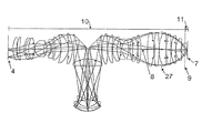
像側のレンズ部分11の領域を図2に部分拡大図として図示した。像側のレンズ部分11は液体13を有し、液体13の屈折率はnFlである。投影レンズ6は屈折率がnAEの光学的シール要素14を有している。光学的シール要素14は像側のレンズ部分11の領域に少なくとも部分的に配置されており、そこで液体13により湿潤させられる。図示した実施形態の場合、光学的シール要素14は平面を像側に配置した平凸レンズとして形成され、この場合参照面9は平凸レンズを横切るように延びている。したがって、平凸レンズのうち、参照面9よりも像側に配置した部分のみが、像側のレンズ部分11の構成要素である。平凸レンズはその一部のみが像側のレンズ部分11に帰属しているにもかかわらず、一体的に製造されていてよい。というのは、参照面9は物理的な分離面ではなく、投影レンズ6の構成を簡潔にするための補助面だからである。同様に、光学的シール要素14をたとえば平行平面板として形成してもよい。光学的シール要素14の材料としては、石英ガラス、弗化カルシウム、または弗化バリウムを使用するのが好ましい。比率は、図1および図2に例示した実施形態では、液体13の屈折率nFlが光学的シール要素14の屈折率nAEよりも大きいように選定されている。
The region of the image-
光学的シール要素14の平面は、液体13が作用する以前に該光学的シール要素14を保護する保護層15で被覆されている。光学的シール要素14と液体13に対し使用される材料によっては保護層15を省略してもよい。光学的シール要素14は、光軸8に平行に、中心厚と呼ばれる延在部を有している。対応的に、中心厚は投影レンズ6の他の構成要素に対しても定義されている。本発明の範囲内では、光学的シール要素14の、参照面9の像側に配置されている部分領域、したがって像側のレンズ部分11に帰属している部分領域が特に重要である。本発明の範囲内では、光学的シール要素14の中心厚に関わる部分は、参照面9の像側に配置されている該光学的シール要素14の部分領域である。このように定義した、光学的シール要素14の中心厚を、符号dAEで表わす。
The plane of the
光学的シール要素14と像面7との間には、液体13で充填されている自由空間16が形成されている。自由空間16は中心厚dFlを有し、以下では像側のレンズ部分11に帰属するものとして説明する。したがって、像側のレンズ部分11は像面7まで延びていることになる。自由空間16は像側で基板18の受光層17によって区画される。受光層17(レジストとも呼ばれ、たとえばフォトレジストから成る)は液体13によって湿潤される。基板18はたとえばウェーハ、特にシリコンウェーハである。
A
基板18は操作装置19上に配置されている。操作装置19はウェーハステージとも呼ばれ、多数の運動能と位置調整能を併せ持っている。たとえば、操作装置19を用いて基板18を光軸8に対し垂直に移動させることができ、この場合の移動はレチクル3の移動に同期して且つレチクル3に対し非平行に行われる。さらに操作装置19は基板18を光軸8に平行に移動させることができ、少なくとも1つの傾動軸線のまわりに傾動運動させることもできる。これにより、基板18の受光層17を投影レンズ6の像面7に正確に配置することが可能となる。
The
光学的シール要素14と基板18との間に液体層を形成させるため、液体供給システム20が設けられている。液体供給システム20は、液体13を自由空間16内へ流入させる少なくとも1つの供給管21と、液体13を自由空間16から排出させる少なくとも1つの排出管22とを有している。供給管21と排出管22とは互いに横方向に対向するように配置されているのが好ましい。供給管21は自由空間16内への液体13の供給量を調節する配量装置23と結合している。排出管22は液体13を自由空間16から排出させるための吸引装置24と結合している。配量装置23と吸引装置24とは浄化ステーション25(たとえばフィルタ、蒸留装置、またはクロマトグラフィーカラムとして構成されている)を介して互いに連通しており、その結果排出管22を介して自由空間16から取り出した液体13を供給管21を介して再び自由空間16に供給することができる。液体13の継続的浄化を必要としない場合には、浄化ステーション25を少なくとも一時的に迂回するようにしてもよい。さらに、液体13を貯留するための貯留器26が設けられている。貯留器26は配量装置23と結合され、たとえば液体のロスを補償したり、或いは、液体13の交換の際に新たな液体13を供給するために用いることができる。
A
さらに、液体供給システム20は、図面には示していないが、制御装置といくつかの測定装置とを有している。これにより液体13の状態を絶えず監視して、液体13の光学特性が可能な限り最適になるように液体の流動が制御される。
Further, the
投影露光装置の作動時、光学的シール要素14と基板18との間にある自由空間16を液体13が連続的に貫流する。すなわち、供給管21を介して自由空間16内へ送られ、排出管22を介して自由空間16から吐き出される。このようにして光学的シール要素14と基板18との間に、所定の光学特性を備えた液体層が形成される。液体層が形成されていると、投影レンズ6の使用範囲が広範となり、照明系2によって照射されたレチクル3を基板18の受光層17上へ結像させる。この場合、液体13は浸漬液として用いられる。このようにして露光された基板18を、この露光によって生じた構造をベースとして加工する。その後さらに露光を行い、この露光をベースとしてさらに加工を行ってもよい。このような処置を基板18が所望の全体構造を有するまで続行する。
During operation of the projection exposure apparatus, the liquid 13 continuously flows through the
投影レンズ6の結像特性はとりわけ液体13の光学特性に依存しており、特に液体13の屈折率nFlに依存している。たとえば屈折率nFlが大きければ、像側の開口数が同じでも焦点深度を大きくすることができる。本発明の範囲内では、投影レンズ6を所望の液体13で作動させることができる。これは像側のレンズ部分11を液体13に整合させることによって達成され、この場合著しく複雑に構成された物体側のレンズ部分10の変更は行わず、或いはわずかな変更のみ行なう。前記整合はすでに投影レンズ6の製造段階で所望の液体13に対し行ない、或いは、後に投影レンズ6を他の液体13に対し変換させる段階で行なう。以下では、本発明を、投影レンズ6を他の液体13に対し変換するケースについて説明する。投影レンズ6を製造する際にもこれに対応した考慮が行なわれるので、このようなケースは特に説明しない。
The imaging characteristics of the
投影レンズ6を他の液体13に対し変換する際に、物体側のレンズ部分10をできるだけ変更しないで済むようにするため、物体側のレンズ部分10と像側のレンズ部分11との間にある参照面9を、変換による状態の変化ができるだけ少ないようなインターフェースと見なす。この点が正確に厳守されればされるほど、物体側のレンズ部分10に対する変更の必要性は少ない。しかしながら、それまで使用していた液体13を、別の屈折率nFlを有する他の液体13に交換することはさしあたりかなりの障害である。この障害は、参照面9の領域での影響ができるだけ少なくなるように像側のレンズ部分11によって補償される。換言すれば、液体13の交換によって生じる開口収差は像側のレンズ部分11の内部でできるだけ正確に補償される。これは、像側のアパーチャーが同じである場合、参照面9の領域における周辺光線の高さと球面収差とがそれぞれ変換前の値とできるだけ正確に同じ値を有しているようなケースである。このようなケースは、定量的には、変換前後の前記値のそれぞれの相対偏差に対する許容最大値を予め設定することによって表わすことができる。周辺光線の高さの相対偏差に対しては、2%の値、好ましくは1%の値を越えてはならず、特に有利には0.5%の値を越えてはならない。この場合、周辺光線の高さは、中心線束に属する1本の周辺光線を参照面9の位置で光軸8に下ろした垂線として定義される。周辺光線の特徴は、投影レンズ6のシステムアパーチャー(以下では開口絞りとも記す)のエッジをかろうじて通過することである。光軸8の領域においてレチクル3から出る光線を中心線束と呼ぶ。球面収差の場合、相対偏差に対する最大値は5%、好ましくは3%、特に1%である。さらに、中心線束の主光線と周辺光線との参照面から像面までの光路差の相対偏差は2%以下、有利には1%以下、特に有利には0.5%以下であるべきである。像側の開口数は1.0よりも大きいのが好ましい。中心線束の主光線の特徴は、投影レンズ6のシステムアパーチャーを光軸8上で通過することである。
When the
液体13に対する像側のレンズ部分11の整合は、特に光学的シール要素14を用いて行うことができる。このため光学的シール要素14を光軸8に平行に移動させることができ、これによってとりわけ液体層の中心厚dFlを制御することができる。また、以前の光学的シール要素14を除去して、その代わりに、異なる中心厚dAEを有し、および/または、他の材料から製造されている光学的シール要素14を取り付けるようにしてもよい。このような光学的シール要素14の変更は、特に、異なる材料から成る平行平面板を新しい光学的シール要素14として取り付けて以前の光学的シール要素14の中心厚dAEを減少させる形態で行なわれる。さらに、光学的シール要素14を保護層15に関し液体13に対し整合させる。すなわち、液体13に対し整合する保護層15を被着させるか、或いは、既存の保護層15がこれから使用する液体13にとって必要でなく、支障をきたす場合にはこの既存の保護層15を除去する。
The alignment of the image-
像側のレンズ部分11の好適な整合は、通常、以下の式、すなわち
SUM=dFl・nFl+dAE・nAE
が変換の前後でほぼ同じ数値となる場合に得られる。使用可能な材料の選択と可能な厚さ範囲には制限があるので、このような最適化にはあまりコストを要しない。変換前後における前記式SUMの相対偏差は2%以下、好ましくは1%以下であるべきである。
A suitable alignment of the image-
SUM = d Fl · n Fl + d AE · n AE
Is obtained when the values are almost the same before and after conversion. Such optimization is less expensive because the choice of usable materials and possible thickness ranges are limited. The relative deviation of the formula SUM before and after conversion should be 2% or less, preferably 1% or less.
像側のレンズ部分11の整合化によって所望の結像品質を達成できない場合には、補助的に、物体側のレンズ部分10において整合処置を行なってもよい。整合処置としては、隣接している個々の光学要素間の内のり間隔を変更させること、或いは、これら光学要素の外形を変更させることも考えられる。これは位置調整装置によって、または、当該光学要素の簡単な交換によって容易に行うことができる。交換に対しては、特に、参照面9または開口絞り或いは共役開口面の付近にある光学要素が対象になる。
If the desired image quality cannot be achieved by the alignment of the image
投影レンズ6の光学系の変更とともに、液体供給システム20の変更を行なって、新しい液体13による可能な限り最適な作動を可能にするようにしてもよい。特に、液体供給システム20の構成要素または液体供給システム20全体を交換することができる。
Along with the change of the optical system of the
次に、投影レンズ6のいくつかの実施形態に対し、像側の開口数は等しいが、屈折率nFlが異なっている液体13を使用したそれぞれ2つの構成例を説明する。なお、第1の構成例は浸漬液としての水に対し整合させたものであり、第2の構成例は高屈折浸漬液に対し整合させたものである。この場合、所望の液体13と該液体に対し整合させた構成例とを投影レンズ6の製造段階で選定するか、或いは、投影レンズ6を所望の液体13に変換し、構成を対応的に整合させることが可能である。
Next, for some embodiments of the
図3は、投影レンズ6の第1実施形態に対する、浸漬液としての水に整合させた構成例を、メリジオナル断面で示したものである。像側のレンズ部分11の領域の拡大部分を図4に図示した。この構成例に付属する構成データは表1と表2にリストアップした。表1は、第1行に、像側の開口数NAとイメージフィールドの高さY’と作動波長λに関する記載を含んでいる。なお、イメージフィールドの高さY’は基板18への投影レンズ6の結像により生じるイメージフィールド内部での光軸8に対する最大間隔を表わすものである。さらに表1には、「SURFACE」と記した列に、物体平面4を起点にカウントしたそれぞれの光学面の番号が記載され、「RADIUS」と記した列には、それぞれの光学面の曲率半径がmmで記載され、「THICNESS」と記した列には、光軸8に沿ったそれぞれ次の光学面までの距離をmmで記載され、「MATERIAL」と記した列には、光学面にそれぞれ対応している光学要素の材料が記載され、「SEMIDIAM.」と記した列には、それぞれの光学要素の光学的に利用可能な範囲の半径がmmで記載されている。他の列にはその他の記載が含まれており、特にそれぞれの光学面が非球面に形成されているかどうかの記載が含まれている。非球面光学面に対しては、表2に、非球面定数がリストアップされている。
FIG. 3 is a meridional section showing an example of the configuration of the
図3には、非球面光学面が一群の短い線で記載してある。さらに図3には開口絞り27も図示した。以下に説明する他の構成例に対しても対応的に作成した表を使用し、非球面光学面を同様に特徴づけている。
In FIG. 3, the aspheric optical surface is indicated by a group of short lines. Further, FIG. 3 also shows an
投影レンズ6の第1実施形態は、2つの膨隆状の放射拡大部と両ビーム拡大部の間にある1つのくびれ状の放射収縮部とを備えた純粋に屈折型の2膨隆系である。この第1実施形態は193nmの作動波長に対し構成されている。像側の開口数はNA=0.95である。図3および図4に図示した構成例においては、投影レンズ6は石英ガラス(溶融石英)から成る屈折率n=1.56の光学要素のみを有している。この場合、光学的シール要素14は石英ガラスから成る平行平面板から形成されている。浸漬液として自由空間16内に水が設けられ、その屈折率はnFl=1.43である。
The first embodiment of the
図5は、高屈折浸漬液に対し整合させた、投影レンズ6の第1実施形態のための構成例をメリジオナル断面で示したものである。像側のレンズ部分11の領域の拡大部分を図6に図示した。付属の構成データは表3と表4にリストアップされている。
FIG. 5 shows, in a meridional section, a configuration example for the first embodiment of the
作動波長と開口数とは図3および図4のものに比べ変更はない。水の代わりに、屈折率がnFl=1.65の高屈折浸漬液を使用する。このような屈折率はたとえば硫酸または燐酸によって実現できる。これは投影レンズ6の他の実施形態に対しても適用する。投影レンズ6を屈折率の変更に対し整合させるため、像側のレンズ部分11で変更を行なった。これに対し物体側のレンズ部分10は変更しなかった。変更事項は表1と表3から明らかである。光学的シール要素14として、弗化カルシウムから成る平行平面板を設けた。光学的シール要素14には、物体側に光学的中間要素28が隣接しており、該光学的中間要素28は石英ガラスから成る平行平面板として形成され、図3と図4のものに比べ新たに付加したものである。さらに、整合処置は投影レンズ6の光軸8に対し平行な方向での光学的シール要素14の位置と光学的中間要素28の位置とへも及んでいる。このため、たとえば、図3と図4のものに比べ光学的シール要素14と像面7との距離が拡大しており、したがって液体層はより厚くなっている。
The operating wavelength and the numerical aperture are not changed compared to those in FIGS. Instead of water, a high refractive immersion liquid having a refractive index of n Fl = 1.65 is used. Such a refractive index can be realized by, for example, sulfuric acid or phosphoric acid. This also applies to other embodiments of the
このようにして変更した像側のレンズ部分11は、変更をしなかった図3の物体側のレンズ部分10と組み合わせて使用可能である。したがって、投影レンズ6の第1実施形態の場合、水を高屈折浸漬液へ変換するために物体側のレンズ部分10の変更は必要ない。高屈折浸漬液に対する整合特性は表13から明らかである。表13においては、水を用いた投影レンズ6の作動と高屈折浸漬液に変換した作動とに対し、それぞれ和SUMと、エッジビームの高さRSHと、主光線と周辺光線との光学的波長差OPDと、球面収差SPHとがリストアップされている。これらの値はそれぞれmmで記載した。さらに、変換前後の作動に対する差値がそれぞれ%で記載されている。また、表には投影レンズ6の他の実施形態に対しても対応値が記載されている。
The image-
図7は、浸漬液としての水に対し整合させた、投影レンズ6の第2実施形態のための構成例をメリジオナル断面で示したものである。像側のレンズ部分11の領域の拡大部分を図8に示した。付属の構成データは表5と表6にリストアップされている。
FIG. 7 shows, in a meridional section, a configuration example for the second embodiment of the
投影レンズ6の第1実施形態と同様に、第2実施形態も約193nmの作動波長に対して設けられ、純粋に屈折型の2膨隆系として構成されている。しかしながら、像側の開口数は第1実施形態の場合よりも大きく、NA=1.1である。図7と図8に図示した構成例は石英ガラスから成る光学要素のみを有しており、浸漬液として水を用いた作動に対し構成されたものである。光学的シール要素14として平凸レンズが設けられ、該平凸レンズは一部が像側のレンズ部分11の領域に配置され、その平面は像側に形成されている。第1実施形態の場合と同様に、第2実施形態でも、他の浸漬液への変換が可能である。
Similar to the first embodiment of the
図9は、高屈折浸漬液に対し整合させた、投影レンズ6の第2実施形態のための構成例をメリジオナル断面で示したものである。像側のレンズ部分11の領域の拡大部分を図10に示した。付属の構成データは表7と表8にリストアップされている。変換用のパラメータは表13に含まれている。
FIG. 9 shows, in a meridional section, a configuration example for the second embodiment of the
図7と図8のものに比べ、作動波長と開口数は変更されていないが、水の代わりに、屈折率がnFl=1.65の高屈折浸漬液を使用する。像側のレンズ部分11をこの高屈折浸漬液に対し整合させるため、前記光学的シール要素14の代わりに、弗化カルシウムから成る平行平面板と石英ガラスから成る平凸レンズとの組み合わせを使用する。この場合、平行平面板を光学的シール要素14として用い、平凸レンズを光学的中間要素28として光学的シール要素14に直接隣接するように物体側に配置する。光学的シール要素14と像面7との内のり間隔は図7および図8のものよりも大きく、その結果液体層はより厚くなっている。
Although the operating wavelength and the numerical aperture are not changed as compared with those of FIGS. 7 and 8, a high refractive immersion liquid having a refractive index of n Fl = 1.65 is used instead of water. In order to align the image-
ところで、第2実施形態の場合、像側のレンズ部分11の上記変更だけでは十分でなく、さらに物体側のレンズ部分10での整合処置が必要である。しかしながら、この整合処置は開口絞り27の両側にある光学要素に限定することができ、すなわち物体側のレンズ部分10の像側端部領域に限定できる。この整合処置の範囲内で、隣接しあっている個々の光学要素間の内のり間隔を変化させる。さらに、非球面に形成されたいくつかの光学要素では、非球面定数を変化させる。詳細は表7と表8から読み取ることができ、特に表5および表6と比較することにより明らかである。整合処置が隣接しあっている個々の光学要素間の内のり間隔の変更に関わるものである限りは、それぞれスライドされる光学要素に対し、光軸8に平行な位置調整可能性を備えさせることができる。非球面定数の変更のためには、該当する光学要素を取り外して後加工するか、或いは他の光学要素と交換する必要がある。それ故、これらの光学要素は簡単に交換できるように取り付けるのが好ましい。
By the way, in the case of the second embodiment, the above-described change of the image-
図11は、浸漬液としての水に対し整合させた、投影レンズ6の第3実施形態のための構成例をメリジオナル断面で示したものである。像側のレンズ部分11の領域の拡大部分を図12に示した。付属の構成データは表9と表10にリストアップされている。
FIG. 11 shows a configuration example for the third embodiment of the
投影レンズ6の第3実施形態も、193nmの作動波長に対し構成されている。しかしながら、第1および第2実施形態とは異なり、第3実施形態は純粋な屈折型ではなく、反射屈折型として構成され、この場合物体側のレンズ部分10は2つの中間像を生成させる。反射光学要素はすべて石英ガラスから製造されている。像側の開口数はNA=1.2である。図11および図12に示した構成例の場合、浸漬液として水を使用する。第2実施形態の場合と同様に、この第3実施形態も光学的シール要素14を有しており、該光学的シール要素14は像側に平面を配置した平凸レンズとして構成され、一部が像側のレンズ部分11内に配置されている。
The third embodiment of the
図13は、高屈折浸漬液に対し整合させた、投影レンズ6の第3実施形態のための構成例をメリジオナル断面で示したものである。像側のレンズ部分11の領域の拡大部分を図14に図示した。付属の構成データは表11と表12にリストアップされている。変換用のパラメータは表13に含まれている。
FIG. 13 shows, in a meridional section, a configuration example for the third embodiment of the
作動波長と開口数は図11および図12のものに比べて変更はない。水の代わりに、屈折率がnFl=1.65の高屈折浸漬液が設けられている。第2実施形態の場合と同様に、光学的シール要素14は弗化カルシウムから成る平行平面板として構成され、物体側には、光学的シール要素14に対し直接隣接するように、石英ガラスから成る平凸レンズとして構成された光学的中間要素28が設けられている。液体層の中心厚dFlは図11および図12に図示したものに比べ大きい。像側のレンズ部分11のこの整合処置以外に、図11のものに比べると、物体側のレンズ部分10も変更されている。変更は物体側のレンズ部分10の像側端部領域に限定されており、開口絞り27の両側にある光学要素のみに限られている。変更は第2実施形態で説明したものと同様に行なわれている。変更の詳細は表11および表12を表9および表10と比較することにより明らかである。
The operating wavelength and the numerical aperture are not changed compared to those in FIGS. Instead of water, a high refractive immersion liquid having a refractive index of n Fl = 1.65 is provided. As in the case of the second embodiment, the
以上説明した投影レンズ6の構成例は、種々の液体13に対し面倒な変更をせずに構成できる可能な構成例の一部のみに関わるものである。水と前記高屈折浸漬液のみが問題なのではなく、基本的には、浸漬作動に適しているものであれば他の任意の液体13でもよい。1つの構成例が適合することのできる可能な液体13の数量にも制限はない。
The configuration example of the

1 光源、2 照明系、3 レチクル、4 物体平面、5 操作装置、6 投影レンズ、7 像面、8 光軸、9 参照面、10 物体側のレンズ部分、11 像側のレンズ部分、13 液体、14 光学的シール要素、15 保護層、16 自由空間、17 受光層、18 基板、19 操作装置、20 液体供給システム、21 供給管、22 排出管、23 配量装置、24 吸引装置、25 浄化ステーション、26 貯留器、27 開口絞り、28 光学的中間要素
DESCRIPTION OF
Claims (43)
Applications Claiming Priority (1)
| Application Number | Priority Date | Filing Date | Title |
|---|---|---|---|
| US68509205P | 2005-05-25 | 2005-05-25 |
Publications (1)
| Publication Number | Publication Date |
|---|---|
| JP2006332669A true JP2006332669A (en) | 2006-12-07 |
Family
ID=37387864
Family Applications (1)
| Application Number | Title | Priority Date | Filing Date |
|---|---|---|---|
| JP2006144146A Pending JP2006332669A (en) | 2005-05-25 | 2006-05-24 | Projection lens suitable for use together with different immersion liquid, and converting method and manufacturing method therefor |
Country Status (3)
| Country | Link |
|---|---|
| US (1) | US7589903B2 (en) |
| JP (1) | JP2006332669A (en) |
| DE (1) | DE102006021161A1 (en) |
Families Citing this family (7)
| Publication number | Priority date | Publication date | Assignee | Title |
|---|---|---|---|---|
| US8208198B2 (en) | 2004-01-14 | 2012-06-26 | Carl Zeiss Smt Gmbh | Catadioptric projection objective |
| US20080151365A1 (en) | 2004-01-14 | 2008-06-26 | Carl Zeiss Smt Ag | Catadioptric projection objective |
| KR20170028451A (en) | 2004-05-17 | 2017-03-13 | 칼 짜이스 에스엠티 게엠베하 | Catadioptric projection objective with intermediate images |
| WO2006133800A1 (en) | 2005-06-14 | 2006-12-21 | Carl Zeiss Smt Ag | Lithography projection objective, and a method for correcting image defects of the same |
| US7773195B2 (en) * | 2005-11-29 | 2010-08-10 | Asml Holding N.V. | System and method to increase surface tension and contact angle in immersion lithography |
| US8184276B2 (en) | 2008-12-08 | 2012-05-22 | Carl Embry | Continuous index of refraction compensation method for measurements in a medium |
| DE102013012182A1 (en) * | 2013-07-22 | 2015-01-22 | Hans-Ulrich Dodt | Modular microscope objective for immersion medium |
Citations (16)
| Publication number | Priority date | Publication date | Assignee | Title |
|---|---|---|---|---|
| JPS5370837A (en) * | 1976-12-04 | 1978-06-23 | Zeiss Stiftung | Immersion objective lens for microscope |
| JPH07220990A (en) * | 1994-01-28 | 1995-08-18 | Hitachi Ltd | Pattern forming method and exposure apparatus thereof |
| JPH10303114A (en) * | 1997-04-23 | 1998-11-13 | Nikon Corp | Immersion type exposure equipment |
| JPH11295609A (en) * | 1998-04-08 | 1999-10-29 | Olympus Optical Co Ltd | Objective lens |
| JP2000058436A (en) * | 1998-08-11 | 2000-02-25 | Nikon Corp | Projection exposure apparatus and exposure method |
| JP2004191920A (en) * | 2002-12-09 | 2004-07-08 | Cark Zeiss Smt Ag | Projection objectivelens for micro lithography or the like, and method for adjusting projection objective lens |
| JP2004205698A (en) * | 2002-12-24 | 2004-07-22 | Nikon Corp | Projection optical system, exposure apparatus and exposure method |
| JP2004333761A (en) * | 2003-05-06 | 2004-11-25 | Nikon Corp | Catadioptric projection optical system, exposure apparatus, and exposure method |
| WO2005001544A1 (en) * | 2003-06-26 | 2005-01-06 | Nikon Corporation | Optical unit, image-forming optical system, method for adjusting aberration of image-forming optical system, projection optical system, method for producing projection optical system, exposure apparatus, and exposure method |
| JP2005079589A (en) * | 2003-08-29 | 2005-03-24 | Asml Netherlands Bv | Lithographic apparatus and device manufacturing method |
| WO2005031823A1 (en) * | 2003-09-29 | 2005-04-07 | Nikon Corporation | Liquid immersion type lens system and projection aligner, device production method |
| JP2005129775A (en) * | 2003-10-24 | 2005-05-19 | Nikon Corp | Catadioptric projection optical system, exposure apparatus and exposure method |
| JP2005184004A (en) * | 2003-12-23 | 2005-07-07 | Asml Netherlands Bv | Lithographic apparatus, alignment apparatus, device manufacture method, alignment method, and apparatus change method |
| JP2005235921A (en) * | 2004-02-18 | 2005-09-02 | Nikon Corp | Optical system adjustment method, imaging optical system, exposure apparatus, and exposure method |
| US20050219707A1 (en) * | 2004-04-02 | 2005-10-06 | Carl Zeiss Smt Ag | Projection objective of a microlithographic exposure apparatus |
| JP2005536775A (en) * | 2002-08-23 | 2005-12-02 | 株式会社ニコン | Projection optical system, photolithography method and exposure apparatus, and method using exposure apparatus |
Family Cites Families (1)
| Publication number | Priority date | Publication date | Assignee | Title |
|---|---|---|---|---|
| US7221514B2 (en) * | 2005-04-15 | 2007-05-22 | Asml Netherlands B.V. | Variable lens and exposure system |
-
2006
- 2006-05-06 DE DE102006021161A patent/DE102006021161A1/en not_active Withdrawn
- 2006-05-24 JP JP2006144146A patent/JP2006332669A/en active Pending
- 2006-05-24 US US11/420,103 patent/US7589903B2/en not_active Expired - Fee Related
Patent Citations (16)
| Publication number | Priority date | Publication date | Assignee | Title |
|---|---|---|---|---|
| JPS5370837A (en) * | 1976-12-04 | 1978-06-23 | Zeiss Stiftung | Immersion objective lens for microscope |
| JPH07220990A (en) * | 1994-01-28 | 1995-08-18 | Hitachi Ltd | Pattern forming method and exposure apparatus thereof |
| JPH10303114A (en) * | 1997-04-23 | 1998-11-13 | Nikon Corp | Immersion type exposure equipment |
| JPH11295609A (en) * | 1998-04-08 | 1999-10-29 | Olympus Optical Co Ltd | Objective lens |
| JP2000058436A (en) * | 1998-08-11 | 2000-02-25 | Nikon Corp | Projection exposure apparatus and exposure method |
| JP2005536775A (en) * | 2002-08-23 | 2005-12-02 | 株式会社ニコン | Projection optical system, photolithography method and exposure apparatus, and method using exposure apparatus |
| JP2004191920A (en) * | 2002-12-09 | 2004-07-08 | Cark Zeiss Smt Ag | Projection objectivelens for micro lithography or the like, and method for adjusting projection objective lens |
| JP2004205698A (en) * | 2002-12-24 | 2004-07-22 | Nikon Corp | Projection optical system, exposure apparatus and exposure method |
| JP2004333761A (en) * | 2003-05-06 | 2004-11-25 | Nikon Corp | Catadioptric projection optical system, exposure apparatus, and exposure method |
| WO2005001544A1 (en) * | 2003-06-26 | 2005-01-06 | Nikon Corporation | Optical unit, image-forming optical system, method for adjusting aberration of image-forming optical system, projection optical system, method for producing projection optical system, exposure apparatus, and exposure method |
| JP2005079589A (en) * | 2003-08-29 | 2005-03-24 | Asml Netherlands Bv | Lithographic apparatus and device manufacturing method |
| WO2005031823A1 (en) * | 2003-09-29 | 2005-04-07 | Nikon Corporation | Liquid immersion type lens system and projection aligner, device production method |
| JP2005129775A (en) * | 2003-10-24 | 2005-05-19 | Nikon Corp | Catadioptric projection optical system, exposure apparatus and exposure method |
| JP2005184004A (en) * | 2003-12-23 | 2005-07-07 | Asml Netherlands Bv | Lithographic apparatus, alignment apparatus, device manufacture method, alignment method, and apparatus change method |
| JP2005235921A (en) * | 2004-02-18 | 2005-09-02 | Nikon Corp | Optical system adjustment method, imaging optical system, exposure apparatus, and exposure method |
| US20050219707A1 (en) * | 2004-04-02 | 2005-10-06 | Carl Zeiss Smt Ag | Projection objective of a microlithographic exposure apparatus |
Also Published As
| Publication number | Publication date |
|---|---|
| DE102006021161A1 (en) | 2006-11-30 |
| US7589903B2 (en) | 2009-09-15 |
| US20080273248A1 (en) | 2008-11-06 |
Similar Documents
| Publication | Publication Date | Title |
|---|---|---|
| US9891539B2 (en) | Projection optical system, exposure apparatus, and exposure method | |
| CN101216682B (en) | Projection optical system, exposure apparatus, and exposure method | |
| US7471374B2 (en) | Projection optical system, exposure apparatus, and exposure method | |
| JP2006332669A (en) | Projection lens suitable for use together with different immersion liquid, and converting method and manufacturing method therefor | |
| US20110134403A1 (en) | Microlithographic projection exposure apparatus | |
| JP2006317753A (en) | Catadioptric imaging optical system, exposure apparatus, and exposure method |
Legal Events
| Date | Code | Title | Description |
|---|---|---|---|
| RD02 | Notification of acceptance of power of attorney |
Free format text: JAPANESE INTERMEDIATE CODE: A7422 Effective date: 20080731 |
|
| RD03 | Notification of appointment of power of attorney |
Free format text: JAPANESE INTERMEDIATE CODE: A7423 Effective date: 20080731 |
|
| A521 | Written amendment |
Free format text: JAPANESE INTERMEDIATE CODE: A821 Effective date: 20080806 |
|
| RD04 | Notification of resignation of power of attorney |
Free format text: JAPANESE INTERMEDIATE CODE: A7424 Effective date: 20080806 |
|
| A621 | Written request for application examination |
Free format text: JAPANESE INTERMEDIATE CODE: A621 Effective date: 20090508 |
|
| A977 | Report on retrieval |
Free format text: JAPANESE INTERMEDIATE CODE: A971007 Effective date: 20110610 |
|
| A131 | Notification of reasons for refusal |
Free format text: JAPANESE INTERMEDIATE CODE: A131 Effective date: 20110704 |
|
| A02 | Decision of refusal |
Free format text: JAPANESE INTERMEDIATE CODE: A02 Effective date: 20111128 |