JP2006289732A - Image recording device - Google Patents
Image recording device Download PDFInfo
- Publication number
- JP2006289732A JP2006289732A JP2005112381A JP2005112381A JP2006289732A JP 2006289732 A JP2006289732 A JP 2006289732A JP 2005112381 A JP2005112381 A JP 2005112381A JP 2005112381 A JP2005112381 A JP 2005112381A JP 2006289732 A JP2006289732 A JP 2006289732A
- Authority
- JP
- Japan
- Prior art keywords
- image recording
- unit
- recording material
- light beam
- light
- Prior art date
- Legal status (The legal status is an assumption and is not a legal conclusion. Google has not performed a legal analysis and makes no representation as to the accuracy of the status listed.)
- Granted
Links
Images


Landscapes
- Handling Of Sheets (AREA)
- Ink Jet (AREA)
Abstract
【課題】従来の画像記録装置においては、被記録材に対する記録ヘッドの画像記録タイミングは、被記録材の端部検出情報をトリガとして、搬送機構における搬送部材の搬送移動距離情報に基づいて生成されるため、搬送機構への被記録材受け渡し搬送時に、被記録材を載置する位置がずれると、画像記録の開始位置がずれてしまうという問題があった。
【解決手段】本発明は、給送系10の下流側に所定の光束を照射する検出部5における投光部5a1,5a2と、プラテン26の上流側に投光部5a1,5a2から照射された光束を受光する検出部5における受光部5b1,5b2を設け、受光部5b1,5b2がこの光束を受光する受光状態によって搬送される被記録材30の端部検出を行なうことにより、給送系10から搬送機構1に受け渡しが完了した後の被記録材30に対する端部検出を可能とする画像記録装置を提供する。
【選択図】 図1In a conventional image recording apparatus, an image recording timing of a recording head with respect to a recording material is generated based on conveyance movement distance information of a conveyance member in a conveyance mechanism, triggered by edge detection information of the recording material. For this reason, when the recording material is transferred to the transport mechanism, if the position where the recording material is placed is shifted, the start position of image recording is shifted.
The present invention relates to light projecting units 5a 1 and 5a 2 in a detecting unit 5 that irradiates a predetermined light beam on the downstream side of a feeding system 10, and light projecting units 5a 1 and 5a 2 on the upstream side of a platen 26. The light receiving portions 5b 1 and 5b 2 are provided in the detecting portion 5 that receives the light beam irradiated from the light receiving portions 5b 1 and 5b 2 to detect the end of the recording material 30 conveyed by the light receiving state in which the light receiving portions 5b 1 and 5b 2 receive the light flux. By doing so, an image recording apparatus is provided that can detect the end of the recording material 30 after the delivery from the feeding system 10 to the transport mechanism 1 is completed.
[Selection] Figure 1
Description
本発明は、被記録材へ画像記録する際の記録ヘッドにおける吐出タイミング生成を行なう画像記録装置に関する。 The present invention relates to an image recording apparatus for generating ejection timing in a recording head when recording an image on a recording material.
記録ヘッドからインクを吐出させ、文字や画像等の情報を記録する液体吐出型記録装置として従来から知られているものに、例えばフルライン型の画像記録装置がある。 For example, a full-line type image recording apparatus is conventionally known as a liquid ejection type recording apparatus that records information such as characters and images by ejecting ink from a recording head.
フルライン型の画像記録装置は、例えば記録紙、OHP用紙等の被記録材の全幅を覆うように記録ヘッドを主走査方向(搬送方向と直交する方向)全体にわたって液体吐出口を配設している。即ち、記録ヘッドは搬送方向と直交する方向でフルライン状に複数のノズルを配列する。被記録材は、複数の記録ヘッドの下方を搬送されることにより単色画像のみならず、カラー画像も記録される形態となっている。 In a full-line type image recording apparatus, for example, a liquid discharge port is disposed over the entire main scanning direction (direction perpendicular to the transport direction) so as to cover the entire width of a recording material such as recording paper or OHP paper. Yes. That is, the recording head arranges a plurality of nozzles in a full line shape in a direction orthogonal to the transport direction. The recording material is configured to record not only a single color image but also a color image by being conveyed below a plurality of recording heads.
次に図12を参照して特許文献1に開示されているフルライン型の画像記録装置について説明する。この従来の装置は、被記録材100を駆動ローラ101及び従動ローラ102といった回転部材により搬送する搬送部103と、インクを吐出する記録ヘッド104と、搬送部103の上流に設けられたレジストローラ対105と、レジストローラ対105のニップ部に設けられた先端検出部106と、により構成されている。
Next, a full-line type image recording apparatus disclosed in Patent Document 1 will be described with reference to FIG. This conventional apparatus includes a
従来の装置は、搬送された被記録材100をニップ部に設けられた先端検出部106が検出することで、予め設定した時間後に記録ヘッド104からインクを吐出する構成である。
また搬送速度は、レジストローラ対105の送り出し速度よりも若干速く、また被記録材100の吸着力は、レジストローラ対105の挟持力よりも強い。
The conveyance speed is slightly higher than the feeding speed of the
しかしながら前述した特許文献1に開示されている従来の装置は、被記録材100がレジストローラ対105から搬送部103へ搬送される際(被記録材100が搬送部103に吸着されるまでの間)に、搬送部103上で被記録材100が滑り(ずれてしまい)、被記録材100の搬送ずれが生じてしまう。これにより画像記録する際、被記録材100への画像記録開始位置は、ずれることになる。
However, the conventional apparatus disclosed in Patent Document 1 described above has a problem in that the
また、搬送部103上で生じる滑りは、被記録材100の材質ごとの摩擦係数で異なるため、仮に被記録材100の滑りの影響を回避するように記録タイミングを補正しようとした場合、被記録材100の材質毎に補正量を変化させる必要がある。
Further, since the slip generated on the
そこで本発明は、材質の異なる被記録材を搬送して画像記録する際、画像記録開始位置が被記録材の滑りによりずれることのない画像記録装置を提供することを目的とする。 SUMMARY OF THE INVENTION Accordingly, an object of the present invention is to provide an image recording apparatus in which an image recording start position does not shift due to slippage of a recording material when an image recording is performed by conveying recording materials of different materials.
本発明は目的を達成するために、被記録材を搬送経路の上流における給送系より搬送経路の下流側へ給送し、給送された被記録材を搬送経路の上方に設けられた画像記録部によって被記録材が搬送経路上を搬送される過程で画像記録を行なう画像記録装置であって、画像記録部に対向配置され、少なくとも被記録材を搬送部材上に載置して搬送する搬送機構と、少なくとも搬送経路における給送系の下流側に設けられ、搬送部材または被記録材のいずれか一方または両方を少なくとも2箇所で検出する検出部と、少なくも搬送機構を制御すると共に、検出部の情報に基づいて画像記録部を制御して画像記録を行なう制御部と、を具備することを特徴とする画像記録装置を提供する。 In order to achieve the object, the present invention feeds a recording material from a feeding system upstream of the conveyance path to the downstream side of the conveyance path, and the fed recording material is provided above the conveyance path. An image recording apparatus that records an image in a process in which a recording material is conveyed on a conveyance path by a recording unit, and is disposed to face the image recording unit, and at least the recording material is placed on a conveying member and conveyed. A transport mechanism, at least downstream of the feeding system in the transport path, a detection unit that detects either or both of the transport member and the recording material in at least two locations, and at least controls the transport mechanism; There is provided an image recording apparatus comprising: a control unit that controls an image recording unit based on information of a detection unit to perform image recording.
本発明によれば、例えば材質の異なる被記録材の画像記録においても、被記録材への画像記録開始位置がずれることのない画像記録装置を提供することができる。 According to the present invention, it is possible to provide an image recording apparatus in which the image recording start position on the recording material does not deviate, for example, even in image recording of recording materials of different materials.
以下、図面を参照して本発明に係る実施形態について詳細に説明する。
図1、図2及び図3を参照して本発明の画像記録装置に係る第1実施形態について詳細に説明する。図1は、本実施形態における画像記録装置のブロック構成図である。
Hereinafter, embodiments according to the present invention will be described in detail with reference to the drawings.
The first embodiment of the image recording apparatus of the present invention will be described in detail with reference to FIG. 1, FIG. 2, and FIG. FIG. 1 is a block diagram of an image recording apparatus according to this embodiment.
図1に示されるように、給送系10より搬送経路下流側に搬送される不図示の被記録材を載置して、搬送経路の下流側に搬送する無端ベルトからなる搬送部材2と、搬送部材2を駆動させる搬送機構駆動部3と、搬送部材2の搬送情報を生成する搬送情報生成部4と、搬送機構駆動部3及び搬送情報生成部4を有する搬送機構1と、搬送機構1に載置された被記録材の端部を検出する検出部5と、検出部5によって通知され、搬送機構1を制御すると共に、画像記録部6を制御して画像記録する制御部9と、から構成される。
As shown in FIG. 1, a conveying
画像記録部6は、記録ヘッド駆動部7と、記録ヘッド駆動部7によって駆動される記録ヘッド8と、から構成される。
制御部9は、不図示の外部装置(本発明の画像記録装置に画像記録要求を発する上位コンピュータ等)から取り込んだ画像記録条件(画像記録枚数、被記録材のサイズ及び解像度(dpi)設定条件等)に基づいて画像記録する。
The
The
制御部9は、例えばCPU及びメモリ等で構成される。また、制御部9は、搬送機構1における搬送機構駆動部3の制御及び搬送情報生成部4からの通知処理、検出部5からの通知処理、画像記録データの一時記憶及び画像記録部6における記録ヘッド駆動部7の制御による記録ヘッド8のインク吐出制御等、本画像記録装置を統括制御する。
The
また、搬送機構駆動部3は、例えばモータ、搬送情報生成部4は、例えばロータリエンコーダ等で構成する。なお、搬送情報生成部4においては、必要に応じてロータリエンコーダにより生成されるパルス信号の周波数を整数倍する高周波発生回路を備えてもよい。
The transport
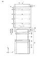
次に、図2及び図3を参照して本実施形態における装置の全体構成を詳細に説明する。図2は、本実施形態における装置構成を模式的に示す概略側面図である。図3は、図2における上面図である。 Next, the overall configuration of the apparatus according to the present embodiment will be described in detail with reference to FIGS. FIG. 2 is a schematic side view schematically showing a device configuration in the present embodiment. FIG. 3 is a top view of FIG.
図2及び図3に示されるように、搬送経路の最上流側に設けられた給送系10は、1枚又は複数の被記録材30を収納する収納部21と、収納された被記録材30を1枚毎取り出して搬送経路下流側に給送する図示しない装置フレームにより回転可能に支持されているピックアップローラ22と、ピックアップローラ22の下流に配置され、被記録材30を挟持するように設けられ、被記録材30の斜行矯正を行なうレジストローラ対23a,23bと、から構成される。レジストローラ対23a,23bは、ピックアップローラ22と同様に装置フレームにより回転可能に支持されている。ピックアップローラ22により給送された被記録材30は、レジストローラ対23a,23bに一旦当接して斜行矯正された後、回転駆動するレジストローラ対23a,23bの挟持/回転により搬送経路下流側へと搬送される。レジストローラ対23a,23bは、位置合わせした後の被記録材30を、搬送機構1に搬送する被記録材搬送部でもある。
As shown in FIGS. 2 and 3, the
なお、以下、被記録材の搬送方向を副走査方向またはX方向、副走査方向に直交する方向を主走査方向またはY方向、これらのXY方向に対して直交する垂直方向をZ方向と称する。 Hereinafter, the conveyance direction of the recording material is referred to as a sub-scanning direction or X direction, a direction orthogonal to the sub-scanning direction is referred to as a main scanning direction or Y direction, and a vertical direction orthogonal to these XY directions is referred to as a Z direction.
レジストローラ対23a,23bの搬送経路の下流側には、複数の吸引孔を有するプラテン26を設けている。プラテン26の上流側に、少なくとも搬送情報生成部4である例えばロータリエンコーダを回転軸に接続する従動ローラ24と、下流側に搬送機構駆動部3である例えばモータを回転軸に接続する駆動ローラ25と、を設けており、またこれらを有する搬送機構1が設けられている。
A
従動ローラ24及び駆動ローラ25は、搬送部材2における複数の真っ直ぐな細長い孔(以下、スリットと称する)を有する無端ベルト2の内側を回動可能に架設している。搬送機構1は、プラテン26の下方に設けられた例えば吸引ファン29によって、吸引チャンバ28、プラテン26及び無端ベルト2を介して被記録材30を吸着保持する。
The driven
搬送機構1の上方に対向配置される画像記録部6は、被記録材30の全幅を覆い、例えばブラック(K)、シアン(C)、マゼンタ(M)、イエロー(Y)等の各色の各記録ヘッド8がX方向に所定の間隔で配設される。また、記録ヘッド8の最上流側に、検出部5における投光部5a1,5a2を配設している。更に、投光部5a1,5a2の対向位置におけるプラテン26には、それぞれ受光部5b1,5b2がプラテン26に形成された孔27a,27bの裏面側に配設されている。また、無端ベルト2は、投光部5a1,5a2から投光された光を、無端ベルト2における所定の回動位置で透過させる複数の孔から成る2つの孔列を有する構成である。(詳細は後述する。)
次に、図4及び図5を参照して画像記録開始位置における被記録材検出方法について詳細に説明する。
図4は、搬送部材である無端ベルト2に形成された複数の孔から成る2つの孔列と検出部5との位置関係等を示す図である。図4に示す無端ベルト2は、検出部5に対し、無端ベルト2が、図面左側(2点鎖線で示す。)から図面右側(実線で示す。)へ直線上に移動した状態を示している。尚、ここでは無端ベルト2上に被記録材30が載置されていない場合について示している。図4(a)は、本装置部分の側面図、図4(b)は、図4(a)の上面図、図4(c)は、検出部5における制御部9への通知出力(タイミングチャート)をそれぞれ示している。
The
Next, the recording material detection method at the image recording start position will be described in detail with reference to FIGS.
FIG. 4 is a diagram showing a positional relationship and the like between the two hole arrays formed of a plurality of holes formed in the
また、図4(b)に示した無端ベルト2の搬送過程において、図面左側に2点鎖線で示した無端ベルト2上に形成された第1及び第2の孔列の孔をそれぞれ31’a1乃至31’a7及び31’b1乃至31’b7と示している。また図面右側に移動し実線で示した無端ベルト2上の第1及び第2の孔列の孔をそれぞれ31a1乃至31a7及び31b1乃至31b7と示している
図4(b)に示すように、無端ベルト2に形成された各孔31a及び31bは、Y方向に所定の距離αだけ離間し、Y方向から見ると、所定の重なりを有して互い違いになるように形成されている。なお、図4(b)において、孔31’a1,31’b1は、孔31a7,31b7と重なっているため図示せずに省略している。
Further, in the process of transporting the
図4(b)に示すように、図面左側において、一方で投光部5a1から投光された光束は、無端ベルト2上の図示しない孔31’a1(図示した孔31a7)及びプラテン26に形成された孔27aを透過した後、受光部5b1によって受光される。他方、投光部5a2から投光された光束は、無端ベルト2上の図示しない孔31’b1(図示した孔31b7)及びプラテン26に形成された孔27bを透過した後、受光部5b2によって受光される。
As shown in FIG. 4 (b), in the left side of the drawing, while the light flux projected from the light projecting portion 5a 1 has a hole 31'a 1 (not shown) on the
また、例えば図面左側に示した無端ベルト2において、投光部5a1,5a2から投光された光束が共に無端ベルト2上の図示しない孔31’a1,31’b1を透過開始した際の時間をt0とする。その後、無端ベルト2が、実線で示す図面右側に移動し、投光部5a1,5a2から投光した光束が、共に実線で示した無端ベルト2上の孔31a7,31b7を透過した時間をt1とする。その結果、図4(c)に示されるように、検出部5は、各受光部5b1,5b2における受光/非受光の繰り返しに基づく制御部9への通知出力を生成する。
Further, for example, in the
なお、本実施形態の制御部9への通知出力生成において、受光部5b1,5b2が、それぞれ受光ならば「High」(以下「H」と記す。)とし、受光部5b1,5b2が、それぞれ非受光ならば「Low」(以下「L」と記す。)と定義する。
In addition, in the notification output generation to the
図4(c)に示す検出部5から制御部9への通知出力によれば、検出部5における投光部5a1,5a2の光束は、共に無端ベルト2上の図示しない孔31’a1,31’b1を透過し、受光部5b1,5b2に共に受光されている。この状態から、無端ベルト2が、図4(b)に示すように右側へ移動(搬送)する過程において、受光部5b1,5b2から制御部9への通知出力は、計時に従い、それぞれ5b1:「H」,5b2:「H」となり、次に5b1:「H」,5b2:「L」となり、次に再び5b1:「H」,5b2:「H」となり、次に5b1:「L」,5b2:「H」の通知出力を繰り返すこととなる。
According to the notification output from the
次に図5は、図4(a)に示した状態に被記録材30が載置されて搬送された状態を示す。
図5(a)は、無端ベルト2に形成された複数の孔から成る2つの孔列、プラテン26に設けられた孔、検出部5及び被記録材30の位置関係等を示す側面図、図5(b)は、無端ベルト2に形成された複数の孔から成る2つの孔列、プラテン26に設けられた孔、検出部5及び被記録材30の位置関係等を示す上面図、図5(c)は、検出部5における制御部9への通知出力(タイミングチャート)、及び検出部5における制御部9への通知出力(受光部5b1,5b2における受光/非受光の結果同士)を論理和した結果(タイミングチャート)で示している。
Next, FIG. 5 shows a state in which the
FIG. 5A is a side view showing a positional relationship between two hole rows formed of a plurality of holes formed in the
なお、図5(b)に示した図面左側に2点鎖線で示した無端ベルト2の移動開始位置(時間:t0)においては、無端ベルト2上に形成された第1及び第2の孔列の孔をそれぞれ31’a1乃至31’a7及び31’b1乃至31’b7で示す。無端ベルト2上の孔31’a7,31’b7が互いにY方向からみて重なりを有する領域に、被記録材のX方向における一方の端部が重なるように載置された被記録材を被記録材30’で示している。
5B, the first and second holes formed on the
また、無端ベルト2が実線で示した図面右側へ移動した位置(時間:t1)において、無端ベルト2上の第1及び第2の孔列の孔をそれぞれ31a1乃至31a7及び31b1乃至31b7で示している。更に各孔が互いにY方向からみて重なりを有する領域に、被記録材の搬送方向における一方の端部が重なるように載置され、投光部5a1,5a2に対し、被記録材の端部が対向している状態の被記録材を被記録材30で示す。
Further, at the position (time: t 1 ) where the
また、図5(b)においても、移動開始位置(時間:t0)における無端ベルト2上の孔31’a1,31’b1は、無端ベルト2が図面右側へ移動した位置(時間:t1)における無端ベルト2上の孔31a7,31b7と重なっているために図示せずに省略している。
Also in FIG. 5 (b), the
図5(c)に示す検出部5における制御部9への通知出力によれば、時間t1において、投光部5a1,5a2に対し、被記録材30の端部が対向しているため、受光部5b1,5b2の制御部9への通知出力は、それぞれ5b1:「L」,5b2:「L」となる。これにより論理和した結果が、常に「L」となる。よって、制御部9への通知出力の論理和した結果が「H」から「L」に変化した位置が、被記録材30の搬送方向端部位置と判別できる。
According to the notification output to the
以上、本実施形態は、給送系10から搬送された被記録材30を搬送機構1に設けられた無端ベルト2上に吸着させてから、被記録材30の端部検出を実施する。端部検出は、搬送された被記録材30に光束を照射した際の受光状態により検出され、制御部9へ通知出力される。被記録材30の端部は、通知出力の論理和した結果により正確に端部位置を検出される。これにより本装置は、例え種類の異なる被記録材を給送系10から搬送機構1へ搬送しても、受け渡し時の滑りによる画像記録のずれが発生しない。
As described above, in the present embodiment, the
従って、被記録材30の端部検出の通知出力結果をトリガ信号として、予め設定される搬送情報生成部4における所定の通知出力(エンコーダパルス数)に基づいて画像記録を行なう。これにより被記録材30に対し、常に画像記録開始位置がずれることのない記録ヘッド吐出タイミング生成を行なう画像記録装置を構築することができる。
Therefore, image recording is performed based on a predetermined notification output (number of encoder pulses) in the conveyance
なお、本実施形態の検出部5は、投光部5a1,5a2を被記録材30のZ方向上方に配設し、受光部5b1,5b2を搬送部2における無端ベルト2の下方におけるプラテン26に形成された孔27a,27bの下方に配設している。しかし、これに限らず投光部5a1,5a2と受光部5b1,5b2をそれぞれ反対の位置に配設してもよい。また、投光部5a1,5a2は、受光部5b1,5b2の両方に対し、一括で照射可能な一つの投光部としてもよい。
In the
次に、図6、図7、図8及び図9を参照して本発明に係る画像記録装置の第2実施形態について詳細に説明する。図6は、本実施形態における概略側面を示す図である。図7は、図6における上面図である。図8は、検出部周辺の概略斜視図である。図9は、検出部の動作を示す図である。
なお、本実施形態においては、前述した第1実施形態と共通の構成要素には同じ参照符号を付し、第1実施形態と同じ作用及び効果については、その詳細な説明を省略する。
Next, a second embodiment of the image recording apparatus according to the present invention will be described in detail with reference to FIG. 6, FIG. 7, FIG. 8, and FIG. FIG. 6 is a diagram showing a schematic side surface in the present embodiment. FIG. 7 is a top view of FIG. FIG. 8 is a schematic perspective view around the detection unit. FIG. 9 is a diagram illustrating the operation of the detection unit.
In the present embodiment, the same reference numerals are given to the same components as those in the first embodiment described above, and the detailed description of the same operations and effects as those in the first embodiment will be omitted.
図6、図7及び図8に示すように本実施形態においては、前述した第1実施形態の構成要素に対し、検出部5が2つの反射型の光学センサに代わっており、投光部5c1と受光部5d1で1個のセンサを、また投光部5c2と受光部5d2で1個のセンサをそれぞれ構成している。
As shown in FIG. 6, FIG. 7 and FIG. 8, in the present embodiment, the
ここで検出部5におけるセンサ5c1,5d1と5c2,5d2が検出する被記録材30からの反射光量をr2、無端ベルト2からの反射光量をr1、被記録材30、または無端ベルト2と共に存在しない(例えば、搬送部材2に孔等が形成されて反射部が無い状態)、または反射光が偏向(例えば、搬送部材2に形成部等が形成されて反射光を偏向する状態)により受光部に入射されない位置での反射光量をr0とすると、反射光量の関係式は以下となっている。
r2≧r1>r0…(1)またはr1≧r2>r0…(2)
上記(1), (2)式は、センサ投光部5c1,5c2から出射された出射光が、被記録材30または無端ベルト2によって反射され、センサ受光部5d1,5d2によって受光される際に、受光されるr2またはr1が、少なくともセンサ受光部5d1,5d2に入射されないr0より共に大きければよいことを示している。つまりr2とr1との大小関係に依存しないことを示している。
また、(1),(2)関係式のr0を生成する構成としては、図8に示す構成としてもよい。
Here, the reflected light amount from the
r 2 ≧ r 1 > r 0 (1) or r 1 ≧ r 2 > r 0 (2)
(1), (2), the sensor
Further, (1), (2) As a configuration for generating r 0 relations may be configured as shown in FIG.
図8に示されるように、無端ベルト2は、被記録材30の搬送方向に略平行に、且つ所定の間隔で直線上に形成された複数の孔における2つの孔列を有している。孔列31a及び31bは、被記録材30の搬送方向に略直交する方向に所定の距離αだけ離間し、孔列の孔同士が、被記録材30の搬送方向に所定の重なりを有して互い違いに形成されている。
As shown in FIG. 8, the
また、無端ベルト2における各孔列のZ方向上方には、それぞれ投光部5c1及び受光部5d1を有する反射型の光学センサと、投光部5c2及び受光部5d2を有する反射型の光学センサと、が配設されている。無端ベルト2の移動により、一方の投光部5c1の照射光が第1の孔列31aを、他方の投光部5c2の照射光が第2の孔列31bを透過するように構成されている。透過した照明光は、下方に配設された少なくとも搬送部材2を支持するプラテン26を照射する。そして、プラテン26は、少なくとも照射光が到達する範囲に、例えば、透過してきた光束をそのまま下方に透過する孔、透過してきた光束を吸光する吸光部、または透過してきた所定の入射角で照射された光束を、所定の入射角に対する反射角と異なる角度に偏向して反射する偏向部といった光束処理部32a及び32bを形成して光束の処理を行ってもよい。
Further, in the Z direction above each hole row in the
次に、図9を参照して本実施形態におけるセンサ5c1,5d1と5c2,5d2における光束検出動作について説明する。図9(a)は、投光部5c1,5c2から出射した光束が孔を透過している状態を示す図である。図9(b)は、投光部5c1から出射した光束が孔を透過し、投光部5c2から出射した光束が無端ベルト2により反射し、受光部5d2が受光している状態を示す図である。図9(c)は、投光部5c1,5c2から出射した光束が被記録材30により反射し、受光部5d1,5d2が受光している状態を示す図である。
Next, with reference to FIG. 9, the light beam detection operation in the
なお、本実施形態は、投光部5c1,5c2から出射した出射光が、受光部5d1または5d2へ入射されない際に、それぞれ受光部5d1:「L」,受光部5d2:「L」と判別し、また入射された際にそれぞれ受光部5d1:「H」,受光部5d2:「H」と判別して、制御部9へ通知出力される。通知を受けた制御部9は、それぞれ受光部5d1:「LまたはH」,受光部5d2:「LまたはH」、このような結果を論理積した結果が「H」の際、被記録材30の端部が検出されたと判別する。
In the present embodiment, when light emitted from the
図9(a)に示すように、例えば一方で投光部5c1から投光された光束5c1outが、第1の孔列の孔31a6を透過している。また他方では、投光部5c2から投光された光束5c2outが、第2の孔列の孔31b6を透過している。共に受光部5d1,5d2への入射光は、各孔を透過しているためにゼロである。
As shown in FIG. 9A, for example, the
従って、受光部5d1,5d2から制御部9への通知出力は、それぞれ受光部5d1:「L」,受光部5d2:「L」となる。よって論理積した結果は、「L」となることから、被記録材30の端部が検出されたと判別しない。
Accordingly, the notification outputs from the
次に、図9(b)に示すように、例えば一方で投光部5c1から投光された光束5c1outは、第1の孔列の孔31a6を透過する。よって反射光は、受光部5d1に入射しない。他方で投光部5c2から投光された光束5c2outは、無端ベルト2によって反射され、受光部5d2に入射する。
従って、受光部5d1,5d2から制御部9への通知出力は、それぞれ受光部5d1:「L」,受光部5d2:「H」となる。よって論理積した結果は、「L」となることから、被記録材30の端部が検出されたと判別しない。
Next, as shown in FIG. 9B, for example, the
Therefore, the notification outputs from the
次に、図9(c)に示すように、例えば一方で投光部5c1から投光された光束5c1outが、被記録材30に反射され受光部5d1に入射する。他方で投光部5c2から投光された光束5c2outも、被記録材30によって反射され受光部5d2に入射される。
従って、受光部5d1,5d2から制御部9への通知出力は、それぞれ受光部5d1:「H」,受光部5d2:「H」となる。よって論理積した結果は、「H」となることから、被記録材30の端部が検出されたと判別する。
Next, as shown in FIG. 9C, for example, the
Accordingly, the notification outputs from the
なお、搬送される被記録材30が斜行し、これにより例えば一方で受光部5d1が被記録材30の反射により受光部5d1:「H」となり、他方で受光部5d2が無端ベルト2からの反射により受光部5d2:「H」となった場合は、被記録材30の端部が検出されたと判別される。
Note that the
しかし、前述したように被記録材30は、無端ベルト2に載置される前に、レジストローラ対23a,23bに一旦当接して斜行矯正されているので斜行量は微小である。
従って、受光部5d1が、被記録材30からの反射により光束5c1outを検出し、他方の受光部5d2が、無端ベルト2からの反射により光束5c2outを検出しても問題はない。
However, as described above, since the
Therefore, there is no problem even if the
以上、本実施形態によれば、給送系10から搬送された被記録材30を、無端ベルト2上に吸着してから、前述した第1の実施形態と同様に被記録材30の端部検出が行なわれるため、給送系10から搬送機構1への被記録材30受け渡し時のずれが生じない。
As described above, according to the present embodiment, after the
次に、図10及び図11を参照して本発明に係る画像記録装置の第3実施形態について説明する。
なお、本実施形態の構成要素について、前述した第1実施形態と同等の構成要素には同じ参照符号を付してその詳細な説明については省略する。
Next, a third embodiment of the image recording apparatus according to the present invention will be described with reference to FIGS.
In addition, about the component of this embodiment, the same referential mark is attached | subjected to the component equivalent to 1st Embodiment mentioned above, and the detailed description is abbreviate | omitted.
本実施形態は、図10に示されるように前述した第1実施形態に、検出機構部11が追加された構成である。
本実施形態は、無端ベルト2上に形成された孔31a1乃至31a7及び31b1乃至31b7に対して投光部5c1と受光部5d1で1個のセンサを構成し、投光部5c2と受光部5d2で1個のセンサを構成する。さらに本実施形態は、移動している無端ベルト上の孔31a1乃至31a7及び31b1乃至31b7が、Y方向(主走査方向)にずれた際に、Y方向における相対位置ずれを補正するものである。
In the present embodiment, as shown in FIG. 10, the
In this embodiment, the
次に、図11(a)、(b)及び(c)を参照して本実施形態に係る画像記録装置の検出機構部11の構成について詳細に説明する。図11(a)は、給送系10方向から搬送方向に見た構成図である。図11(b)は、無端ベルト2とプラテン26との境界部を検知する構成を示した図である。図11(c)は、検出機構部11の動作を示す図である。
Next, the configuration of the
図11(a)に示すように検出部5を垂下するように支持する検出機構部11は、画像記録部6に対しY0方向に移動可能に設けられている。また、検出機構部11は、例えば検知部11aと、モータ11bと、支持材11cと、支持ガイド11d及びラック部11eとで構成される。
As shown in FIG. 11A, the
支持ガイド11dは、画像記録部6のY方向に略平行に配設され、支持材11cを水平移動可能に支持する。モータ11bは、支持材11cに固定される。また、モータ11bの回転軸に圧入されたピニオンギヤ11fは、画像記録部6に形成されるラック部11eに噛合い、モータ11bの回転により、支持材11cに垂下された検出部5及び検知部11aを一体的にY方向に移動させる構成である。
The
また、図11(b),(c)に示すように検知部11aは、例えばLED、LD等から構成される光源部11a1と、コリメートレンズ11a2と、フォトディテクタ11a3と、光源部11a1の制御回路及びフォトディテクタ11a3のI/V変換回路を有するドライブ基板11a4と、により構成されている。ドライブ基板11a4は、フォトディテクタ11a3に入射された光量に基づく電圧を制御部9へ通知する。
Further, the
次に、図11(c)を参照して検出機構部11の動作について詳細に説明する。
図11(c)に示されるように、無端ベルトにずれが生じない場合、光源部11a1より照射された光束は、コリメートレンズ11a2で一旦平行光束に変換される。変換された平行光束は、光束の略半分を無端ベルトに照射すると共に、残り半分の光束をプラテン26に照射するように構成される。
Next, the operation of the
As shown in FIG. 11 (c), if no deviation occurs in the endless belt, the light beam emitted from the
従って、無端ベルト2とプラテン26との境界部33において、無端ベルト2からの反射光束及びプラテン26からの反射光束は、フォトディテクタ11a3に出射される。無端ベルト2からの反射光束に基づく反射光量をr1、プラテン26からの反射光束に基づく反射光量をr3とする。よってフォトディテクタ11a3は、r1とr3を合わせた総反射量であるr5を受光することになる。ドライブ基板11a4は、総反射量:r5に基づく電圧V0を制御部9に通知する。
Therefore, at the
図11(c)に示すように、r1とr3の関係がr3>r1であり、例えば移動中の無端ベルトがY方向内側(搬送機構1の中心に向けた方向)にずれた際、無端ベルト2による反射光束は、細く、またプラテン26からの反射光束は、太くなる。これによりフォトディテクタ11a3における受光面上でr3の占める割合が増加し、r1の割合は減少することになる。結果、無端ベルトがよれていない時のr5に基づく電圧V0に対し、V’0に変動することになる(V0<V’0)。
As shown in FIG. 11C, the relationship between r 1 and r 3 is r 3 > r 1 , for example, the moving endless belt is displaced inward in the Y direction (direction toward the center of the transport mechanism 1). At this time, the reflected light beam from the
そこで、光源部11a1の出射光量を一定に保つと共に、制御部9で電圧V0を予め記憶しておく。無端ベルト2の移動中に、制御部9が常に電圧V0を保つように検出機構部11を制御し、検出部5をY0方向に相対的に移動させる。
Therefore, the light quantity emitted from the
これにより無端ベルト移動中にずれが発生しても、無端ベルト2に形成された孔31a1乃至31a7及び31b1乃至31b7と、検出部5とのY方向における相対位置ずれを補正することができる。
Thus, even if a deviation occurs during the movement of the endless belt, the relative positional deviation in the Y direction between the
以上、本実施形態によれば、無端ベルトがY方向(主走査方向)によれた場合にも、無端ベルトに形成された孔31a1乃至31a7及び31b1乃至31b7と、検出部5とのY方向における相対位置ずれを補正できるため、被記録材30の端部検出を確実に行なうことができる。
As described above, according to the present embodiment, even when the endless belt is in the Y direction (main scanning direction), the
また、本発明は、前述した第1実施形態、第2実施形態及び第3実施形態に限定されるものではなく、実施の段階では、その要旨を逸脱しない範囲で構成要素を変形して具体化できる。 In addition, the present invention is not limited to the first embodiment, the second embodiment, and the third embodiment described above, and at the stage of implementation, the constituent elements may be modified and embodied without departing from the spirit of the invention. it can.
前述した第2実施形態及び第3実施形態は、無端ベルトに形成された孔31a1乃至31a7及び31b1乃至31b7の代わりに、例えば、各孔の形成部において、所定の入射角で照射された光束を入射角に対する反射角と異なる角度に偏向して反射する偏向部を形成する。これにより投光部5c1,5c2から投光する光束を偏向部により受光部5d1,5d2が受光できない反射角で反射する構成とすることができる。また形成部は、透過してきた光束を吸光する吸光部を有してもよい。
In the second embodiment and the third embodiment described above, instead of the
また、前述した第1実施形態及び第2実施形態は、無端ベルト2に形成された孔31a1乃至31a7及び31b1乃至31b7の代わりに、例えば、各孔の形成部分において、被記録材30及び無端ベルト2の反射率に対し、より反射率が高い、または低い反射部を形成することでも実現できる。
例えば、形成部分の反射率が高い場合においては、被記録材30の端部は、「L」と検出され、無端ベルト2の非形成部が「L」と検出されると、論理積結果が「L」で判別できる。また形成部分の反射率が低い場合においては、被記録材30の端部検出で「H」、無端ベルトの非形成部が「H」これらの論理積結果が「H」で判別できる。
Further, in the first embodiment and the second embodiment described above, instead of the
For example, when the reflectance of the formed portion is high, the end of the
また、第1実施形態、第2実施形態及び第3実施形態に開示されている複数の構成要素の適宜組み合わせにより、種々の発明を形成できる。例えば、第1実施形態、第2実施形態及び第3実施形態に示される全体構成要素から幾つかの構成要素を削除してもよい。さらに、異なる実施形態に亘る構成要素を適宜組み合わせてもよい。 Various inventions can be formed by appropriately combining a plurality of constituent elements disclosed in the first embodiment, the second embodiment, and the third embodiment. For example, you may delete a some component from the whole component shown by 1st Embodiment, 2nd Embodiment, and 3rd Embodiment. Furthermore, you may combine the component covering different embodiment suitably.
1…搬送機構、2…搬送部材(無端ベルト)、3…搬送機構駆動部、4…搬送情報生成部、5…検出部、5a1,5a2,5c1,5c2…投光部、5b1,5b2,5d1,5d2…受光部、6…画像記録部、7…記録ヘッド駆動部、8…記録ヘッド、9…制御部、10…給送系、11…検出機構部、11a…検知部、11a1…光源部、11a2…コリメータレンズ、11a3…フォトディテクタ、11a4…ドライブ基板、11b…モータ、11c…支持材、11d…支持ガイド、11e…ラック部、11f…ピニオンギヤ、21…収納部、22…ピックアップローラ、23a,23b…レジストローラ、24…従動ローラ、25…駆動ローラ、26…プラテン、27a,27b,31a1,31a2,31a3,31a4,31a5,31a6,31a7及び31b1,31b2,31b3,31b4,31b5,31b6,31b7,31’a1,31’a2,31’a3,31’a4,31’a5,31’a6,31’a7及び31’b1,31’b2,31’b3,31’b4,31’b5,31’b6,31’b7…孔、28…吸引チャンバ、29…吸引ファン、30,30’…被記録材、32a,32b…光束処理部、33…境界部。 1 ... conveyor mechanism, 2 ... conveying member (endless belt), 3 ... transporting mechanism driving section, 4 ... transporting information generation unit, 5 ... detector, 5a 1, 5a 2, 5c 1, 5c 2 ... projecting portion, 5b 1, 5b 2, 5d 1, 5d 2 ... light-receiving section, 6 ... image recording section, 7 ... recording head drive unit, 8 ... recording head, 9 ... controller, 10 ... feeding system, 11 ... detection device, 11a Detecting section 11a 1 Light source section 11a 2 Collimator lens 11a 3 Photo detector 11a 4 Drive board 11b Motor 11c Support material 11d Support guide 11e Rack section 11f Pinion gear 21 ... storage part, 22 ... pick-up roller, 23a, 23b ... registration roller 24 ... driven roller, 25 ... driving roller, 26 ... platen, 27a, 27b, 31a 1, 31a 2, 31a 3, 31a 4, 31a 5, 31a 6 , 31a 7 and 31b 1, 31b 2, 31b 3 , 31b 4, 31b 5, 31b 6, 31b 7, 31'a 1, 31'a 2, 31'a 3, 31 ' a 4 , 31′a 5 , 31′a 6 , 31′a 7 and 31′b 1 , 31′b 2 , 31′b 3 , 31′b 4 , 31′b 5 , 31′b 6 , 31 ′ b 7 ... hole, 28 ... suction chamber, 29 ... suction fan, 30, 30 '... recording material, 32a, 32b ... light beam processing part, 33 ... boundary part.
Claims (26)
前記画像記録部に対向配置され、少なくとも前記被記録材を搬送部材上に載置して搬送する搬送機構と、
少なくとも前記搬送経路における前記給送系の下流側に設けられ、前記搬送部材または前記被記録材のいずれか一方または両方を少なくとも2箇所で検出する検出部と、
少なくも前記搬送機構を制御すると共に、前記検出部の情報に基づいて前記画像記録部を制御して画像記録を行なう制御部と、
を具備することを特徴とする画像記録装置。 The recording material is fed to the downstream side of the conveying path from the feeding system on the upstream side of the conveying path, and the fed recording material is sent by the image recording unit provided above the conveying path. An image recording apparatus for recording an image in a process in which a recording material is conveyed on the conveyance path,
A transport mechanism disposed opposite to the image recording unit and configured to transport at least the recording material on a transport member;
A detection unit that is provided at least on the downstream side of the feeding system in the conveyance path and detects either one or both of the conveyance member and the recording material in at least two locations;
A control unit that controls at least the transport mechanism and controls the image recording unit based on information of the detection unit to perform image recording;
An image recording apparatus comprising:
前記検出機構部が、前記検出部に、前記搬送部材と前記プラテン部との境界部分を検出させることを特徴とする請求項1記載の画像記録装置。
The image recording unit further includes a detection mechanism unit that supports the detection unit so as to be movable in a direction substantially perpendicular to the conveyance direction of the recording material,
The image recording apparatus according to claim 1, wherein the detection mechanism unit causes the detection unit to detect a boundary portion between the transport member and the platen unit.
Priority Applications (1)
| Application Number | Priority Date | Filing Date | Title |
|---|---|---|---|
| JP2005112381A JP5005182B2 (en) | 2005-04-08 | 2005-04-08 | Image recording device |
Applications Claiming Priority (1)
| Application Number | Priority Date | Filing Date | Title |
|---|---|---|---|
| JP2005112381A JP5005182B2 (en) | 2005-04-08 | 2005-04-08 | Image recording device |
Publications (3)
| Publication Number | Publication Date |
|---|---|
| JP2006289732A true JP2006289732A (en) | 2006-10-26 |
| JP2006289732A5 JP2006289732A5 (en) | 2008-05-15 |
| JP5005182B2 JP5005182B2 (en) | 2012-08-22 |
Family
ID=37410845
Family Applications (1)
| Application Number | Title | Priority Date | Filing Date |
|---|---|---|---|
| JP2005112381A Expired - Fee Related JP5005182B2 (en) | 2005-04-08 | 2005-04-08 | Image recording device |
Country Status (1)
| Country | Link |
|---|---|
| JP (1) | JP5005182B2 (en) |
Cited By (1)
| Publication number | Priority date | Publication date | Assignee | Title |
|---|---|---|---|---|
| JP2012131128A (en) * | 2010-12-22 | 2012-07-12 | Riso Kagaku Corp | Image forming apparatus |
Citations (4)
| Publication number | Priority date | Publication date | Assignee | Title |
|---|---|---|---|---|
| JP2001113690A (en) * | 1999-10-22 | 2001-04-24 | Canon Aptex Inc | Printer |
| JP2002103598A (en) * | 2000-07-26 | 2002-04-09 | Olympus Optical Co Ltd | Printer |
| JP2004009529A (en) * | 2002-06-06 | 2004-01-15 | Canon Inc | Recording device and recording method |
| JP2004074554A (en) * | 2002-08-16 | 2004-03-11 | Toppan Printing Co Ltd | Inkjet printing machine |
-
2005
- 2005-04-08 JP JP2005112381A patent/JP5005182B2/en not_active Expired - Fee Related
Patent Citations (4)
| Publication number | Priority date | Publication date | Assignee | Title |
|---|---|---|---|---|
| JP2001113690A (en) * | 1999-10-22 | 2001-04-24 | Canon Aptex Inc | Printer |
| JP2002103598A (en) * | 2000-07-26 | 2002-04-09 | Olympus Optical Co Ltd | Printer |
| JP2004009529A (en) * | 2002-06-06 | 2004-01-15 | Canon Inc | Recording device and recording method |
| JP2004074554A (en) * | 2002-08-16 | 2004-03-11 | Toppan Printing Co Ltd | Inkjet printing machine |
Cited By (1)
| Publication number | Priority date | Publication date | Assignee | Title |
|---|---|---|---|---|
| JP2012131128A (en) * | 2010-12-22 | 2012-07-12 | Riso Kagaku Corp | Image forming apparatus |
Also Published As
| Publication number | Publication date |
|---|---|
| JP5005182B2 (en) | 2012-08-22 |
Similar Documents
| Publication | Publication Date | Title |
|---|---|---|
| JP5495682B2 (en) | Recording apparatus and recording method | |
| JP2004188954A (en) | Inkjet recording apparatus | |
| JP5608583B2 (en) | Table creation method, recording medium floating detection device, and image recording device | |
| JP4110907B2 (en) | Recording apparatus, recording method, program, and computer system | |
| WO2004091917A1 (en) | Device, system, and method for discharging liquid | |
| JP2005138489A (en) | Image position correcting system for image forming device, and its image position correcting method | |
| JP5631691B2 (en) | Image recording apparatus and method for controlling image recording apparatus | |
| JP5115521B2 (en) | Printing apparatus and printing method | |
| JP2005186475A (en) | Image forming range variable system of image forming apparatus and method of varying image forming range therefor | |
| JP2007223790A (en) | Transport device | |
| JP5668280B2 (en) | Printing apparatus and edge detection method of printing medium | |
| JP5005182B2 (en) | Image recording device | |
| JP2012076442A (en) | Recording apparatus | |
| US7828400B2 (en) | Image forming apparatus having position detection mechanism | |
| JP2007001183A (en) | Image forming apparatus | |
| JP4900442B2 (en) | Inkjet recording device | |
| JP3453525B2 (en) | Recording device | |
| US7402828B2 (en) | Position detector that prevents erroneous detection of a scale and liquid ejecting apparatus incorporating the same | |
| JP4349035B2 (en) | Inkjet recording device | |
| JP4735178B2 (en) | Inkjet printer | |
| JP2009166999A (en) | Paper flotation sensor | |
| JP4649342B2 (en) | Recording material floating detection system provided in image recording apparatus | |
| JP6891566B2 (en) | Printing equipment | |
| JP2005059425A (en) | Ink jet recorder | |
| JP4492147B2 (en) | Ink jet recording apparatus and recording medium movement control method |
Legal Events
| Date | Code | Title | Description |
|---|---|---|---|
| A521 | Request for written amendment filed |
Free format text: JAPANESE INTERMEDIATE CODE: A523 Effective date: 20080331 |
|
| A621 | Written request for application examination |
Free format text: JAPANESE INTERMEDIATE CODE: A621 Effective date: 20080331 |
|
| A131 | Notification of reasons for refusal |
Free format text: JAPANESE INTERMEDIATE CODE: A131 Effective date: 20100817 |
|
| A521 | Request for written amendment filed |
Free format text: JAPANESE INTERMEDIATE CODE: A523 Effective date: 20100927 |
|
| A02 | Decision of refusal |
Free format text: JAPANESE INTERMEDIATE CODE: A02 Effective date: 20101102 |
|
| A521 | Request for written amendment filed |
Free format text: JAPANESE INTERMEDIATE CODE: A523 Effective date: 20110121 |
|
| A911 | Transfer to examiner for re-examination before appeal (zenchi) |
Free format text: JAPANESE INTERMEDIATE CODE: A911 Effective date: 20110201 |
|
| A711 | Notification of change in applicant |
Free format text: JAPANESE INTERMEDIATE CODE: A711 Effective date: 20110225 |
|
| A912 | Re-examination (zenchi) completed and case transferred to appeal board |
Free format text: JAPANESE INTERMEDIATE CODE: A912 Effective date: 20110225 |
|
| A711 | Notification of change in applicant |
Free format text: JAPANESE INTERMEDIATE CODE: A711 Effective date: 20110616 |
|
| A711 | Notification of change in applicant |
Free format text: JAPANESE INTERMEDIATE CODE: A712 Effective date: 20111201 |
|
| A521 | Request for written amendment filed |
Free format text: JAPANESE INTERMEDIATE CODE: A523 Effective date: 20120322 |
|
| A01 | Written decision to grant a patent or to grant a registration (utility model) |
Free format text: JAPANESE INTERMEDIATE CODE: A01 |
|
| A61 | First payment of annual fees (during grant procedure) |
Free format text: JAPANESE INTERMEDIATE CODE: A61 Effective date: 20120523 |
|
| FPAY | Renewal fee payment (event date is renewal date of database) |
Free format text: PAYMENT UNTIL: 20150601 Year of fee payment: 3 |
|
| R150 | Certificate of patent or registration of utility model |
Free format text: JAPANESE INTERMEDIATE CODE: R150 Ref document number: 5005182 Country of ref document: JP Free format text: JAPANESE INTERMEDIATE CODE: R150 |
|
| R250 | Receipt of annual fees |
Free format text: JAPANESE INTERMEDIATE CODE: R250 |
|
| R250 | Receipt of annual fees |
Free format text: JAPANESE INTERMEDIATE CODE: R250 |
|
| R250 | Receipt of annual fees |
Free format text: JAPANESE INTERMEDIATE CODE: R250 |
|
| R250 | Receipt of annual fees |
Free format text: JAPANESE INTERMEDIATE CODE: R250 |
|
| R250 | Receipt of annual fees |
Free format text: JAPANESE INTERMEDIATE CODE: R250 |
|
| R250 | Receipt of annual fees |
Free format text: JAPANESE INTERMEDIATE CODE: R250 |
|
| R250 | Receipt of annual fees |
Free format text: JAPANESE INTERMEDIATE CODE: R250 |
|
| R250 | Receipt of annual fees |
Free format text: JAPANESE INTERMEDIATE CODE: R250 |
|
| R250 | Receipt of annual fees |
Free format text: JAPANESE INTERMEDIATE CODE: R250 |
|
| LAPS | Cancellation because of no payment of annual fees |