JP2006233921A - Control device for compression self-ignition internal combustion engine - Google Patents
Control device for compression self-ignition internal combustion engine Download PDFInfo
- Publication number
- JP2006233921A JP2006233921A JP2005052526A JP2005052526A JP2006233921A JP 2006233921 A JP2006233921 A JP 2006233921A JP 2005052526 A JP2005052526 A JP 2005052526A JP 2005052526 A JP2005052526 A JP 2005052526A JP 2006233921 A JP2006233921 A JP 2006233921A
- Authority
- JP
- Japan
- Prior art keywords
- secondary air
- egr
- internal combustion
- combustion engine
- self
- Prior art date
- Legal status (The legal status is an assumption and is not a legal conclusion. Google has not performed a legal analysis and makes no representation as to the accuracy of the status listed.)
- Pending
Links
Images




Classifications
-
- F—MECHANICAL ENGINEERING; LIGHTING; HEATING; WEAPONS; BLASTING
- F02—COMBUSTION ENGINES; HOT-GAS OR COMBUSTION-PRODUCT ENGINE PLANTS
- F02M—SUPPLYING COMBUSTION ENGINES IN GENERAL WITH COMBUSTIBLE MIXTURES OR CONSTITUENTS THEREOF
- F02M26/00—Engine-pertinent apparatus for adding exhaust gases to combustion-air, main fuel or fuel-air mixture, e.g. by exhaust gas recirculation [EGR] systems
- F02M26/02—EGR systems specially adapted for supercharged engines
- F02M26/03—EGR systems specially adapted for supercharged engines with a single mechanically or electrically driven intake charge compressor
-
- F—MECHANICAL ENGINEERING; LIGHTING; HEATING; WEAPONS; BLASTING
- F02—COMBUSTION ENGINES; HOT-GAS OR COMBUSTION-PRODUCT ENGINE PLANTS
- F02M—SUPPLYING COMBUSTION ENGINES IN GENERAL WITH COMBUSTIBLE MIXTURES OR CONSTITUENTS THEREOF
- F02M26/00—Engine-pertinent apparatus for adding exhaust gases to combustion-air, main fuel or fuel-air mixture, e.g. by exhaust gas recirculation [EGR] systems
- F02M26/13—Arrangement or layout of EGR passages, e.g. in relation to specific engine parts or for incorporation of accessories
- F02M26/36—Arrangement or layout of EGR passages, e.g. in relation to specific engine parts or for incorporation of accessories with means for adding fluids other than exhaust gas to the recirculation passage; with reformers
Landscapes
- Engineering & Computer Science (AREA)
- Chemical & Material Sciences (AREA)
- Combustion & Propulsion (AREA)
- Mechanical Engineering (AREA)
- General Engineering & Computer Science (AREA)
- Exhaust-Gas Circulating Devices (AREA)
- Output Control And Ontrol Of Special Type Engine (AREA)
Abstract
【課題】 圧縮自己着火燃焼を行なう内燃機関において、低負荷領域でのHC排出量を低減でき、該自己着火燃焼運転の領域を拡大して燃費も改善できるようにした。
【解決手段】
2次空気をEGR通路12の入口上流側にの排気通路11部分に供給する2次空気通路17を設け、その出口付近に2次空気用燃料噴射弁19を設け、かつ、2次空気による噴射燃料および排気中未燃HCの酸化反応(燃焼)を促進するためのグロープラグ20が設け、低負荷領域で、2次空気と燃料の供給によって燃焼加熱された排気を外部EGRとして吸気系に還流する構成とし、筒内温度を上昇させて自己着火性を高めるようにした。
【選択図】 図1PROBLEM TO BE SOLVED: To reduce the amount of HC emission in a low load region in an internal combustion engine that performs compression self-ignition combustion, and to expand the region of the self-ignition combustion operation to improve fuel consumption.
[Solution]
A secondary air passage 17 for supplying secondary air to the exhaust passage 11 portion upstream of the inlet of the EGR passage 12 is provided, a secondary air fuel injection valve 19 is provided near the outlet, and injection by the secondary air is performed. A glow plug 20 is provided to promote the oxidation reaction (combustion) of fuel and unburned HC in the exhaust, and the exhaust heated by combustion by the supply of secondary air and fuel is returned to the intake system as external EGR in a low load region. In this configuration, the in-cylinder temperature is increased to increase the self-ignitability.
[Selection] Figure 1
Description
本発明は、圧縮自己着火燃焼を行なう内燃機関の燃料噴射装置に関する。 The present invention relates to a fuel injection device for an internal combustion engine that performs compression self-ignition combustion.
特許文献1には、圧縮自己着火燃焼を行う内燃機関において、点火時期の遅角、混合気の増量などによって内部EGRを昇温することにより、自己着火性を高めるようにすることが開示されている。
特許文献2には、同じく圧縮自己着火燃焼を行なう内燃機関において、新気を加熱し、排気バルブの閉時期により残留ガス(内部EGR)量を増量して、自己着火性を高めるようにすることが開示されている。
In
しかしながら、特許文献1、2のように、内部EGRによって昇温を図ることは、内部EGRが前サイクルの燃焼状態に依存するので、全気筒を安定的に次サイクルで自己着火燃焼させることができないという問題がある。
本発明は、このような従来の課題に着目してなされたもので、安定した自己着火性能の向上を図れるようにすることを目的とする。
However, as in
The present invention has been made paying attention to such a conventional problem, and an object of the present invention is to improve stable self-ignition performance.
そのため、本発明は、圧縮自己着火燃焼を行なう内燃機関において、燃焼により加熱した排気を、外部EGRとして吸気系に還流する構成とした。 Therefore, according to the present invention, in an internal combustion engine that performs compression self-ignition combustion, the exhaust gas heated by the combustion is recirculated to the intake system as an external EGR.
かかる構成によると、燃焼加熱された外部EGRによって筒内温度を全気筒で応答良く要求温度まで上昇させることができ、安定した自己着火性能の向上を図れる。 According to such a configuration, the in-cylinder temperature can be raised to the required temperature with good response in all cylinders by the externally heated EGR that is heated by combustion, and stable self-ignition performance can be improved.
以下に本発明の実施の形態を図面に基づいて説明する。
図1は、第1実施形態における圧縮自己着火内燃機関のシステム構成図である。
内燃機関1(ガソリンエンジン)には、吸気通路2の上流側から、エアクリーナ3を通過した空気が、過給機4で過給された後、吸気バルブ5を介してシリンダ6内に吸引される。
Embodiments of the present invention will be described below with reference to the drawings.
FIG. 1 is a system configuration diagram of a compression self-ignition internal combustion engine in the first embodiment.
In the internal combustion engine 1 (gasoline engine), the air that has passed through the
前記シリンダ6内に直接燃料を噴射する燃料噴射弁7が設けられている。
燃焼室内の混合気は、圧縮自己着火又は点火プラグ8による火花点火によって着火燃焼し、燃焼排気は、排気バルブ9を介して排出される。
前記吸気バルブ4及び排気バルブ9には、バルブリフト量,バルブ作動角及び作動角の中心位相を可変とする可変動弁機構10が設けられている。
A
The air-fuel mixture in the combustion chamber is ignited and combusted by compression self-ignition or spark ignition by the
The
前記可変動弁機構10は、例えば、特開2001−012262号公報に開示される機関バルブのバルブリフト量を作動角と共に連続的に変化させる可変バルブイベント・リフト機構(VEL)と、クランクシャフトに対するカムシャフトの回転位相を変化させることで、バルブ作動角の中心位相を可変とする可変バルブタイミング機構(VTC)との組み合わせから構成される。
The
また、前記可変動弁機構10を、吸気バルブ5及び排気バルブ9を電磁石による磁気力で開閉駆動する電磁駆動弁(EMV)とすることができる。
前記排気バルブ9下流の排気通路11からの排気を、外部EGRとして過給機4下流の吸気通路2に還流するEGR通路12が設けられる。
前記EGR通路12の途中に、EGRクーラ13を介装したバイパス通路14が並列に接続され、該バイパス通路14の入口部分に、EGR通路12とバイパス通路14とを選択的に開閉する通路切換弁15が設けられ、EGR通路12の出口部は、外部EGR量を制御するEGRバルブ16が設けられる。
The
There is provided an EGR
In the middle of the EGR
前記過給機4出口とEGR通路12出口との間から取り入れた2次空気を、前記EGR通路12の入口上流側に近接した排気通路11部分に供給する2次空気通路17が設けられ、該2次空気通路17内の入口付近に2次空気ポンプ18が設けられ、出口付近に燃料を噴射供給する2次空気用燃料噴射弁19が設けられる。
前記2次空気通路17出口と、EGR通路12入口との間の排気通路11壁に、2次空気による噴射燃料および排気中未燃HCの酸化反応(燃焼)を促進するためのグロープラグ20が設けられる。
A secondary air passage 17 is provided for supplying secondary air taken from between the outlet of the
On the wall of the
前記排気通路11のEGR通路12接続部より下流側には、排気浄化触媒31が設けられる。
前記燃料噴射弁6、点火プラグ8、可変動弁機構10、通路切換弁15、EGRバルブ16、2次空気ポンプ18、2次空気用燃料噴射弁19、グロープラグ20は、マイクロコンピュータを内蔵するエンジンコントロールユニット(ECU)21によって制御される。
An
The
前記エンジンコントロールユニット21には、機関回転数を検出する回転数センサ22、機関の冷却水温度を検出する水温センサ23、シリンダ内の温度を検出するシリンダ内温度センサ24、排気温度を検出する排気温度センサ25等からの検出信号が入力される。
図2、図3のフローチャートは、第1実施形態における前記エンジンコントロールユニット21による外部EGR昇温制御の様子を示す。
The
The flowcharts of FIGS. 2 and 3 show the state of the external EGR temperature increase control by the
ステップS1では、アクセル開度などによって算出された要求トルクT、前記回転数センサ20によって検出された機関回転数Neを読み込む。
ステップS2では、前記要求トルクTおよび機関回転数Neによって検出される運転状態に基づいて、圧縮自己着火燃焼と火花点火燃焼とのいずれの燃焼形態で運転させるかを決定する。
In step S1, the required torque T calculated by the accelerator opening and the engine speed Ne detected by the
In step S2, based on the operating state detected by the required torque T and the engine speed Ne, it is determined whether to operate in the compression self-ignition combustion mode or the spark ignition combustion mode.
具体的には、機関トルクTが、自己着火可能最大トルクTHよりも小さく、かつ、自己着火可能最小トルクTLよりも大きく(TL<T<TH)、かつ、機関回転数Ne(rpm)が、自己着火可能最大回転数NeHよりも小さく、かつ、自己着火可能最小回転数NeLよりも大きいときに(NeL<Ne<NeH)、圧縮自己着火燃焼の可能領域内であると判断し、上記条件を満たさないときには、火花点火燃焼を行なわせる領域内であると判断する。 Specifically, the engine torque T is smaller than the self-ignitable maximum torque TH, larger than the self-ignitable minimum torque TL (TL <T <TH), and the engine speed Ne (rpm) is When it is smaller than the maximum self-ignitable rotation speed NeH and larger than the minimum self-ignition possible rotation speed NeL (NeL <Ne <NeH), it is determined that it is within the region where compression self-ignition combustion is possible, and the above condition is satisfied. When it is not satisfied, it is determined that it is within the region where spark ignition combustion is performed.
そして、圧縮自己着火燃焼の可能領域内であると判断されると、ステップS4以降に進み、火花点火燃焼を行なわせる領域内であると判断されると、ステップS3進む。
ステップS2では、燃料噴射弁6から噴射される燃料を点火プラグ8による火花点火で燃焼させる火花点火燃焼制御を行なわせる。
一方、ステップS4では、本発明に係る圧縮自己着火燃焼制御を開始する。
If it is determined that it is within the region where compression self-ignition combustion is possible, the process proceeds to step S4 and subsequent steps, and if it is determined that it is within the region where spark ignition combustion is performed, the process proceeds to step S3.
In step S2, spark ignition combustion control is performed to burn the fuel injected from the
On the other hand, in step S4, the compression self-ignition combustion control according to the present invention is started.
ステップS5では、前記排気温度センサ23によって検出された排気温度txを読み込む。
ステップS6では、図4に示したマップを参照して前記要求トルクTが所定以上の高負荷領域であるかを判定し、該高負荷領域と判定されたときは、ステップS7へ進んで、前記通路切換弁15を、バイパス通路14開側に制御して、外部EGRをいるクーラ13によって冷却する。
なお、高負荷領域においても、負荷が高くなるほど通路切換弁15をバイパス通路14側の開度が大きくなるようにして、冷却量を増大制御する。
また、前記2次空気ポンプ18による2次空気の供給および2次空気用燃料噴射弁19からの燃料噴射は停止する。
In step S5, the exhaust temperature tx detected by the
In step S6, with reference to the map shown in FIG. 4, it is determined whether or not the required torque T is a high load region that is greater than or equal to a predetermined value. The
Even in the high load region, the amount of cooling is controlled to increase by increasing the opening of the
Further, the supply of secondary air by the
ステップS6で、要求トルクTが所定未満の領域と判定された場合は、ステップS8へ進んで、前記通路切換弁15を、バイパス通路14閉(EGR通路12の主通路開)側に制御して、外部EGRのクーラ13による冷却を停止する。
ステップS9では、前記要求トルクTおよび機関回転数Neに基づき、図5に示したマップを参照して、要求筒内温度tcを算出する。
If it is determined in step S6 that the required torque T is less than the predetermined range, the process proceeds to step S8 to control the
In step S9, the required in-cylinder temperature tc is calculated based on the required torque T and the engine speed Ne with reference to the map shown in FIG.
具体的には、負荷が高くなるほど、また、機関回転数Neが高くなるほど要求筒内温度tcが高温に設定される。
ステップS10では、前記排気温度センサ23で検出された排気温度txと、前記要求筒内温度tcとに基づいて、図6に示したマップを参照して、要求2次空気量Q2を算出する。
Specifically, the required in-cylinder temperature tc is set to a higher temperature as the load increases and as the engine speed Ne increases.
In step S10, the required secondary air amount Q2 is calculated with reference to the map shown in FIG. 6 based on the exhaust temperature tx detected by the
具体的には、要求筒内温度tcが得られるように2次空気量が設定されるが、排気温度txが低いときほど、低負荷でHC排出量が増大するので、要求筒内温度tcが高くなるほど、また、排気温度txが低くなるほど要求2次空気量Q2が大きく設定される。
前記要求2次空気量Q2が得られるように、前記2次空気ポンプ18の駆動量が制御される。
Specifically, the secondary air amount is set so that the required in-cylinder temperature tc is obtained. However, as the exhaust gas temperature tx is lower, the HC discharge amount increases at a lower load. The required secondary air amount Q2 is set larger as the exhaust temperature tx becomes higher as the exhaust temperature becomes higher.
The driving amount of the
ステップS11では、前記排気温度tx、要求筒内温度tcとに基づいて、図7に示したマップを参照して、要求2次空気用燃料噴射量Ti2を算出する。具体的には、要求筒内温度tcが得られるように、2次空気による酸化反応(燃焼)を促進するため、オーバーリッチ状態となるように設定される。
前記要求2次空気用燃料噴射量Ti2が得られるように、前記2次空気用燃料噴射弁19の通電量(開弁時間)が制御される。
In step S11, the required secondary air fuel injection amount Ti2 is calculated based on the exhaust temperature tx and the required in-cylinder temperature tc with reference to the map shown in FIG. Specifically, in order to promote the oxidation reaction (combustion) by the secondary air so as to obtain the required in-cylinder temperature tc, the over-rich state is set.
The energization amount (valve opening time) of the secondary air
ステップS12では、2次空気量(実測値または要求値Q2)から、図8に示したテーブルを参照して、排気温度の上昇率αを算出する。2次空気量が増大するほど、2次空気による酸化反応が促進されて温度上昇率αが増大するように設定されている。
ステップS13では、前記排気温度tx、2次空気量Q2、温度上昇率αを用いて、次式により、2次空気による酸化反応(燃焼)後の排気温度tx2を算出する。
In step S12, the exhaust gas temperature increase rate α is calculated from the secondary air amount (measured value or required value Q2) with reference to the table shown in FIG. It is set so that as the amount of secondary air increases, the oxidation reaction by the secondary air is promoted and the temperature increase rate α increases.
In step S13, the exhaust temperature tx2 after the oxidation reaction (combustion) by the secondary air is calculated by the following equation using the exhaust temperature tx, the secondary air amount Q2, and the temperature increase rate α.
tx2=tx+Q2×α・・・(1)
ステップS14では、前記酸化反応後の排気温度tx2と、要求筒内温度tcとに基づいて、図9に示したマップを参照して、要求グロープラグ発熱量tgを算出する。
すなわち、要求筒内温度tcを得るため、2次空気による酸化反応が促進されるように、グロープラグ20によって、雰囲気温度を上昇させ、2次空気だけでは要求筒内温度tcが得られない領域で外部熱を供給してアシストする。
tx2 = tx + Q2 × α (1)
In step S14, the required glow plug heat generation amount tg is calculated with reference to the map shown in FIG. 9 based on the exhaust temperature tx2 after the oxidation reaction and the required in-cylinder temperature tc.
That is, in order to obtain the required in-cylinder temperature tc, the atmosphere temperature is raised by the
前記要求グロープラグ発熱量tgが得られるように、前記グロープラグ20の通電量を制御する。
ステップS15では、機関回転数Neとグロープラグ20による温度上昇代とに基づいて、図10に示したマップを参照して、グロープラグ20の発熱量に対する温度上昇の感度係数Aを算出する。
ここで、グロープラグ20による温度上昇代Δtxgとは、要求外部EGR温度tertと前記2次空気による酸化反応(燃焼)後の排気温度tx2との温度差(Δtxg=tert−tx2)として算出され、該温度上昇代Δtxgが高いときほど発熱量に対する温度上昇が大きいので感度係数Aは大きくなるように設定されるが、機関回転数Neが高くなるほど排気流速が大きくなって温度上昇しにくくなるので、感度係数Aは小さくなるように設定されている。
ステップS16では、前記グロープラグ発熱量tg、感度係数A、酸化反応後の排気温度tx2とに基づいて、図11に示したマップを参照して、要求外部EGR量に見合った要求EGRバルブ開度θを算出する。
前記要求EGRバルブ開度が得られるように、EGRバルブ16が制御される。
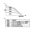
図12は、圧縮自己着火燃焼運転での領域毎の制御内容を示し、最も低負荷な領域Aでは、2次空気量、2次空気用燃料噴射量およびグロープラグ発熱量のレベルを大とし、領域Aより負荷の大きな領域Bでは、2次空気量、2次空気用燃料噴射量およびグロープラグ発熱量のレベルを中とし、領域Bより高負荷な領域Cでは、2次空気量および2次空気用燃料噴射量のレベルを小とし、グロープラグの通電は停止する。なお、領域A〜CではEGRクーラによる外部EGRの冷却は停止されている。
最も高負荷な領域Dでは、上述したように2次空気ポンプ18による2次空気の供給および2次空気用燃料噴射弁19からの燃料噴射は停止し、外部EGRの冷却を冷却する。
図13は、上記領域A〜D毎の各種状態量および制御量を、2次空気供給有り(これに付随する2次空気用燃料噴射、グロープラグによる発熱を含む)と無しの場合を比較して示す。
本実施形態のように領域A〜Cでは、2次空気供給等を行って燃焼加熱することにより、外部EGRが温度上昇し、筒内温度上昇によって安定した自己着火性を確保できる。
これにより、燃焼室からのHC排出量を低減でき、かつ、吸入空気量の多い自己着火燃焼では低温な排気の温度を上昇させることにより排気浄化触媒の活性を早められることの相乗効果によって、特に低負荷領域でのHC排出量を大幅に低減できる。
また、上記のように安定した自己着火性の確保によって自己着火燃焼運転領域を拡大でき(特に低負荷で高回転側へ拡大できる)でき、燃費も改善できる。
一方、高負荷領域Dでは、外部EGRを冷却することによって筒内温度の上昇を抑制することにより燃焼速度が過大となることを抑制して緩慢な燃焼を得ることができ、自己着火燃焼運転領域を高負荷側へ拡大でき、燃費を改善できる。
図13では、高負荷領域で2次空気供給をしたときに、HCが低減しているが、実際には、高負荷領域で外部EGRを加熱して筒内温度を上昇させると、燃焼速度が過大となってノッキング等の異常燃焼を発生しやすくなるので、自己着火燃焼が可能な負荷領域が低負荷側に大きく制約されてしまう。したがって、実質的には、高負荷側に自己着火燃焼運転領域が拡大されることにより、火花着火運転を行った場合と比較して燃費を低減できる。
図14は、機関回転数Neの変化に応じた各種状態量の変化を示す。
図示のように、2次空気供給により外部EGRの加熱を行うことにより、特に低回転側で触媒温度の早期活性化が図れ、これに伴い、HC排出量を十分に低減できる。
図15は、図13、図14で示した以外の本実施形態の要因別の効果を示す。
図15(A)は、上記特許文献1,2に示したような内部EGRによる自己着火性向上を図った場合と、外部EGRの温度上昇による場合とを自己着火性向上を図った場合と比較したもので、内部EGRによる場合は、筒内圧力変動率の気筒間でのバラツキが大きいのに対し、外部EGRによる場合は、筒内圧力変動率の気筒間でのバラツキを小さく抑制できる。
図15(B)は、2次空気による外部EGR温度上昇により自己着火燃焼運転領域が、高回転側および低負荷側に拡大することを示している。
図15(C)は、外部EGRの冷却により、高負荷限界が拡大することを示している。
図15(D)は、グロープラグの発熱により、2次空気供給のみの場合に比較して外部EGRをより温度上昇させて、自己着火燃焼運転領域が、さらに低負荷側および高回転側に拡大することを示している。
このように、本実施形態では、自己着火燃焼運転で問題となる低負荷でのHCを十分に低減しながら、該自己着火燃焼運転領域を拡大できることによって、燃費を向上できる。
なお、本実施形態では、2次空気用の燃料を供給し、グロープラグによる発熱も行っているので、2次空気の供給だけでは排気中の未燃HCを酸化燃焼させることが難しい場合でも確実に燃焼させて浄化することができる。
また、これら2次空気用燃料の供給、グロープラグの発熱に伴う燃費の損失はあるが、温度上昇によって自己着火燃焼運転領域を拡大できることによりトータルとして燃費を低減できるように燃料噴射量、発熱量を制御することができる。なお、外部EGRを電気ヒーターで加熱する方式も考えられるが、この方式では、温度上昇効率が低いため消費電力が大きくなり、また、排気温度を上昇させるものではないので、排気中の未燃HCを燃焼させることができず、かつ、排気浄化触媒の活性を早める効果も有しないので、HC浄化性能を十分向上できるものではない。
図16は、本発明の別の実施形態を示す。
本実施形態では、EGR通路12’の入口(外部EGR導入口)を、HCの酸化反応による浄化機能を有する排気浄化触媒31の下流側に接続すると共に、EGRクーラ13’を介装したバイパス通路14’の入口を、前記排気浄化触媒31の上流側に接続し、該バイパス通路14’の出口をEGR通路12’の下流側に合流させて接続し、該合流点にバイパス通路14’と主通路とを選択的に開閉する通路切換弁15’を設けた構成とする。
そして、自己着火燃焼運転する領域において、所定以上の高負荷領域(第1実施形態での領域D)では、前記バイパス通路14’を開として外部EGRをEGRクーラ13’によって冷却する。
上記高負荷領域以外の領域では、バイパス通路14’を閉として外部EGRの冷却を停止すると共に、前記排気浄化触媒13で排気中の未燃HCが酸化反応したとき発生した熱で温度上昇した排気を外部EGRとすることで、筒内温度を上昇させ、低負荷でのHC排出量を低減しながら自己着火燃焼運転領域を拡大することができる。
The energization amount of the
In step S15, the temperature rise sensitivity coefficient A with respect to the heat generation amount of the
Here, the temperature increase allowance Δtxg by the
In step S16, based on the glow plug heat generation amount tg, the sensitivity coefficient A, and the exhaust temperature tx2 after the oxidation reaction, referring to the map shown in FIG. 11, the required EGR valve opening corresponding to the required external EGR amount is obtained. θ is calculated.
The
FIG. 12 shows the control contents for each region in the compression self-ignition combustion operation. In the region A where the load is the lowest, the level of the secondary air amount, the secondary air fuel injection amount, and the glow plug heat generation amount are increased. In the region B where the load is larger than the region A, the level of the secondary air amount, the fuel injection amount for the secondary air, and the glow plug heat generation amount are medium, and in the region C where the load is higher than the region B, the secondary air amount and the secondary air amount are increased. The level of the fuel injection amount for air is reduced, and energization of the glow plug is stopped. In the areas A to C, the cooling of the external EGR by the EGR cooler is stopped.
In the highest load region D, as described above, the supply of the secondary air by the
FIG. 13 compares various state quantities and control quantities for each of the regions A to D with and without secondary air supply (including secondary fuel injection for the secondary air and heat generated by the glow plug) and without. Show.
In the regions A to C as in the present embodiment, by performing secondary heating and the like to perform combustion heating, the temperature of the external EGR rises, and stable self-ignitability can be secured due to the rise in the in-cylinder temperature.
As a result, the amount of HC emissions from the combustion chamber can be reduced, and in the self-ignition combustion with a large intake air amount, the synergistic effect that the activity of the exhaust purification catalyst can be accelerated by raising the temperature of the low-temperature exhaust gas. HC emissions in the low load area can be greatly reduced.
Further, by ensuring stable self-ignitability as described above, the self-ignition combustion operation region can be expanded (especially, it can be expanded to a high rotation side at a low load), and fuel consumption can be improved.
On the other hand, in the high load region D, it is possible to obtain a slow combustion by suppressing an increase in the in-cylinder temperature by cooling the external EGR, thereby suppressing the combustion rate from becoming excessive, and a self-ignition combustion operation region. Can be expanded to higher loads, and fuel efficiency can be improved.
In FIG. 13, HC is reduced when the secondary air is supplied in the high load region, but actually, when the external EGR is heated in the high load region and the in-cylinder temperature is increased, the combustion rate is increased. Since it becomes excessive and abnormal combustion such as knocking is likely to occur, the load region in which self-ignition combustion is possible is greatly restricted to the low load side. Therefore, the fuel consumption can be reduced as compared with the case where the spark ignition operation is performed by substantially expanding the self-ignition combustion operation region on the high load side.
FIG. 14 shows changes in various state quantities according to changes in the engine speed Ne.
As shown in the figure, by heating the external EGR by supplying secondary air, the catalyst temperature can be activated early, particularly on the low rotation side, and accordingly, the HC emission amount can be sufficiently reduced.
FIG. 15 shows effects according to factors of the present embodiment other than those shown in FIGS. 13 and 14.
FIG. 15A compares the case where the self-ignition performance is improved by internal EGR as shown in
FIG. 15B shows that the self-ignition combustion operation region expands to the high rotation side and the low load side due to the rise in the external EGR temperature due to the secondary air.
FIG. 15C shows that the high load limit is expanded by cooling the external EGR.
In FIG. 15D, the temperature of the external EGR is further increased by the heat generated by the glow plug as compared with the case where only the secondary air is supplied, and the self-ignition combustion operation region is further expanded to the low load side and the high rotation side. It shows that
Thus, in this embodiment, fuel consumption can be improved by expanding the self-ignition combustion operation region while sufficiently reducing HC at a low load, which is a problem in self-ignition combustion operation.
In this embodiment, since fuel for secondary air is supplied and heat is generated by the glow plug, even if it is difficult to oxidize and burn unburned HC in the exhaust gas only by supplying secondary air, it is reliable. It can be burned and purified.
In addition, although fuel consumption is lost due to the supply of fuel for the secondary air and the heat generation of the glow plug, the fuel injection amount and the heat generation amount can be reduced so that the fuel consumption can be reduced as a whole by expanding the self-ignition combustion operation region due to the temperature rise. Can be controlled. Although a method of heating the external EGR with an electric heater is also conceivable, in this method, the temperature rise efficiency is low, so that the power consumption is large and the exhaust temperature is not raised. HC cannot be burned and has no effect of accelerating the activity of the exhaust purification catalyst, so that the HC purification performance cannot be sufficiently improved.
FIG. 16 illustrates another embodiment of the present invention.
In this embodiment, the inlet (external EGR introduction port) of the
In a region where the self-ignition combustion operation is performed, in a high load region (region D in the first embodiment) that is equal to or greater than a predetermined value, the external EGR is cooled by the
In regions other than the high load region, the bypass passage 14 'is closed to stop the cooling of the external EGR, and the exhaust gas whose temperature has risen due to the heat generated when the unburned HC in the exhaust gas undergoes an oxidation reaction at the exhaust
本実施形態では、第1実施形態ほど外部EGRを十分に温度上昇させることは難しく、排気浄化触媒の早期活性化も図れないが、特別な温度上昇手段を設けることなく、簡易な構成で済む。 In the present embodiment, it is difficult to raise the temperature of the external EGR sufficiently as in the first embodiment, and the exhaust purification catalyst cannot be activated at an early stage.
1…内燃機関、7…燃料噴射弁、8…点火プラグ、10…可変動弁機構、11…排気通路、12,12’…EGR通路、13、13’…EGRクーラ、14、14’…バイパス通路、15、15’…通路切換弁、16…EGRバルブ、17…2次空気通路、18…2次空気ポンプ、19…2次空気用燃料噴射弁、20…グロープラグ、21…エンジンコントロールユニット、22…回転数センサ、23…水温センサ、25…排気温度センサ、31…排気浄化触媒
DESCRIPTION OF
Claims (10)
Priority Applications (1)
| Application Number | Priority Date | Filing Date | Title |
|---|---|---|---|
| JP2005052526A JP2006233921A (en) | 2005-02-28 | 2005-02-28 | Control device for compression self-ignition internal combustion engine |
Applications Claiming Priority (1)
| Application Number | Priority Date | Filing Date | Title |
|---|---|---|---|
| JP2005052526A JP2006233921A (en) | 2005-02-28 | 2005-02-28 | Control device for compression self-ignition internal combustion engine |
Publications (1)
| Publication Number | Publication Date |
|---|---|
| JP2006233921A true JP2006233921A (en) | 2006-09-07 |
Family
ID=37041850
Family Applications (1)
| Application Number | Title | Priority Date | Filing Date |
|---|---|---|---|
| JP2005052526A Pending JP2006233921A (en) | 2005-02-28 | 2005-02-28 | Control device for compression self-ignition internal combustion engine |
Country Status (1)
| Country | Link |
|---|---|
| JP (1) | JP2006233921A (en) |
Cited By (4)
| Publication number | Priority date | Publication date | Assignee | Title |
|---|---|---|---|---|
| JP2010163964A (en) * | 2009-01-15 | 2010-07-29 | Toyota Motor Corp | Control device of internal combustion engine and control device of vehicle |
| JP2011185235A (en) * | 2010-03-11 | 2011-09-22 | Hino Motors Ltd | Exhaust emission control device of diesel engine |
| JP2014047629A (en) * | 2012-08-29 | 2014-03-17 | Mazda Motor Corp | Spark ignition type direct-injection engine |
| US9624868B2 (en) | 2012-09-07 | 2017-04-18 | Mazda Motor Corporation | Spark-ignition direct injection engine |
-
2005
- 2005-02-28 JP JP2005052526A patent/JP2006233921A/en active Pending
Cited By (4)
| Publication number | Priority date | Publication date | Assignee | Title |
|---|---|---|---|---|
| JP2010163964A (en) * | 2009-01-15 | 2010-07-29 | Toyota Motor Corp | Control device of internal combustion engine and control device of vehicle |
| JP2011185235A (en) * | 2010-03-11 | 2011-09-22 | Hino Motors Ltd | Exhaust emission control device of diesel engine |
| JP2014047629A (en) * | 2012-08-29 | 2014-03-17 | Mazda Motor Corp | Spark ignition type direct-injection engine |
| US9624868B2 (en) | 2012-09-07 | 2017-04-18 | Mazda Motor Corporation | Spark-ignition direct injection engine |
Similar Documents
| Publication | Publication Date | Title |
|---|---|---|
| EP1245815B1 (en) | Direct-injection spark-ignition engine with a turbo-charging device, engine control method , and computer-readable storage medium therefor | |
| US6817349B2 (en) | Control system and method and engine control unit for compression ignition internal combustion engine | |
| EP2264303B1 (en) | Control method and device of engine and corresponding engine | |
| JP3257423B2 (en) | Exhaust heating device | |
| US8783227B2 (en) | Engine control method and apparatus | |
| CN103375282B (en) | Automatic ignition explosive motor and the method for the explosive motor of the operating type that part is disabled | |
| US8025046B2 (en) | System and method for facilitating homogeneous charge compression ignition | |
| EP2357345A2 (en) | Method and apparatus for controlling supercharged engine during compression self-ignition combustion | |
| US8539932B2 (en) | Systems and methods for heating intake air during cold HCCI operation | |
| CN102884300A (en) | Control method of spark ignition engine and spark ignition engine | |
| WO2008026686A1 (en) | Operating method of premixed compression self-ignition engine | |
| JP3799898B2 (en) | In-cylinder injection engine control device | |
| JP3880296B2 (en) | Engine control device | |
| US7703438B2 (en) | System and method for facilitating homogeneous charge compression ignition | |
| JP2007016685A (en) | Control device for internal combustion engine | |
| JP2012041895A (en) | Control device for compression self-ignition engine | |
| JP4180995B2 (en) | Control device for compression ignition internal combustion engine | |
| JP4560978B2 (en) | Spark ignition direct injection engine with turbocharger | |
| JP4098684B2 (en) | Control device for compression ignition internal combustion engine | |
| JP2006233921A (en) | Control device for compression self-ignition internal combustion engine | |
| JP3835238B2 (en) | Diesel engine control device | |
| JP4102268B2 (en) | Compression ignition internal combustion engine | |
| JP5925099B2 (en) | Control device for internal combustion engine | |
| JP4538976B2 (en) | Spark ignition direct injection engine with turbocharger | |
| EP1867849A2 (en) | Homogeneous charge compression ignition engine |