JP2006226760A - Image measuring apparatus - Google Patents
Image measuring apparatus Download PDFInfo
- Publication number
- JP2006226760A JP2006226760A JP2005039002A JP2005039002A JP2006226760A JP 2006226760 A JP2006226760 A JP 2006226760A JP 2005039002 A JP2005039002 A JP 2005039002A JP 2005039002 A JP2005039002 A JP 2005039002A JP 2006226760 A JP2006226760 A JP 2006226760A
- Authority
- JP
- Japan
- Prior art keywords
- edge
- tool
- image
- tracking
- point
- Prior art date
- Legal status (The legal status is an assumption and is not a legal conclusion. Google has not performed a legal analysis and makes no representation as to the accuracy of the status listed.)
- Pending
Links
Images




Landscapes
- Length Measuring Devices By Optical Means (AREA)
Abstract
Description
本発明は、ワークの画像を撮像し、この画像を基にしてワークに非接触でワークの測定を実行する画像測定装置に関する。 The present invention relates to an image measuring apparatus that captures an image of a workpiece and performs measurement of the workpiece without contacting the workpiece based on the image.
非接触三次元測定機や顕微鏡測定機に代表される画像測定装置は、ワークの測定対象となる箇所(以下、測定箇所という)をCCDカメラ等で撮像して得られた画像から測定箇所のエッジを検出し、これを基にして測定箇所やワーク全体の形状や寸法等を計測する精密測定機器である。 An image measuring apparatus typified by a non-contact three-dimensional measuring machine or a microscope measuring machine uses a CCD camera or the like to image a part to be measured on a workpiece (hereinafter referred to as a measuring part), and the edge of the measuring part. Is a precision measuring instrument that detects the shape and dimensions of the measurement location and the entire workpiece based on this.
エッジは、ディスプレイ上に測定箇所の画像と重ねて表示されるツールを用いて検出される。連続するエッジを測定することのできるオートトレースツールには、直線状に移動するツールや円弧状に移動するツール等がある。測定箇所に対応させて、これらのツール単独で又はこれらを組み合わせてエッジを検出していた。 The edge is detected using a tool displayed on the display so as to overlap the image of the measurement location. Examples of the auto trace tool that can measure continuous edges include a tool that moves in a straight line and a tool that moves in an arc. The edge is detected by using these tools alone or in combination in correspondence with the measurement location.
直線状の移動のような定められた動きをするツールによりエッジを検出するのでは、測定箇所のエッジが自由曲線の場合、一つのツールでエッジの検出を終わらせることができない。このため、画像測定装置の中には、測定箇所のエッジを自動的に追跡するツール(オートトレース用のツール)により、エッジを検出しているものもある(例えば、特許文献1参照)。
しかし、オートトレース用のツールでは、エッジを誤って追跡した場合、測定箇所の測定スタート点から、エッジ検出をもう一度やり直す必要があり、オペレータにとって大変面倒であった。 However, in the case of the tool for auto tracing, when the edge is traced incorrectly, it is necessary to perform edge detection again from the measurement start point of the measurement location, which is very troublesome for the operator.
本発明は、エッジ検出の誤りを少なくできると共にエッジ検出のやり直しの手間を少なくできる画像測定装置を提供することを目的とする。 It is an object of the present invention to provide an image measuring apparatus that can reduce errors in edge detection and reduce the trouble of redoing edge detection.
本発明に係る画像測定装置は、ワークの測定箇所の画像及びその測定箇所のエッジを検出するための枠状のツールを重ねて表示する表示手段と、前記表示手段に表示された前記測定箇所の画像上でエッジ検出の区間を定める中継点を指示する指示手段と、中継点が指示される毎にその中継点により定められた区間のエッジを、前記ツールにより追跡させてその区間のエッジを検出する検出手段と、を備え、前記検出手段は、前記ツール内の前記エッジの画像情報から前記ツール内の複数のエッジ点を抽出し、得られた複数のエッジ点に近似直線を当てはめると共に、この近似直線に沿って一部の領域が現在のツールに重なるように次の新たなツールを生成する、エッジ追跡手段を含むことを特徴とする。 An image measuring apparatus according to the present invention includes a display unit that displays an image of a measurement location of a workpiece and a frame-shaped tool for detecting an edge of the measurement location, and a display unit that displays the measurement location displayed on the display unit. Instructing means for instructing a relay point for defining an edge detection section on the image, and every time a relay point is designated, the edge of the section defined by the relay point is tracked by the tool to detect the edge of the section Detecting means for extracting a plurality of edge points in the tool from the image information of the edge in the tool, and applying an approximate straight line to the obtained plurality of edge points. The image processing apparatus includes an edge tracking unit that generates a next new tool so that a part of the area overlaps the current tool along the approximate straight line.
本発明に係る画像測定装置によれば、中継点が指示される毎にその中継点により定められた区間のエッジを、ツールにより追跡させてその区間のエッジを検出している。したがって、エッジ追跡の精度が上がるので、エッジ検出の誤りを少なくできる。また、仮にエッジ追跡の経路を誤っても、その誤った区間の中継点からエッジ追跡を再開すればよいので、エッジ検出のやり直しの手間を少なくできる。 According to the image measuring apparatus of the present invention, every time a relay point is designated, the edge of the section defined by the relay point is tracked by the tool to detect the edge of the section. Therefore, since the accuracy of edge tracking is improved, errors in edge detection can be reduced. Further, even if the edge tracking route is wrong, it is only necessary to resume edge tracking from the relay point of the wrong section, so that it is possible to reduce the trouble of performing edge detection again.
本発明に係る画像測定装置において、指示された中継点により定められた区間のエッジ追跡を省略するスキップ手段を備えるようにすることができる。これによれば、エッジ上に障害物が存在する場合、その区間のエッジ追跡を省略することにより、エッジ検出の際に障害物の影響を受けないようにすることができる。 In the image measuring apparatus according to the present invention, it is possible to provide skip means for omitting edge tracking in a section defined by an instructed relay point. According to this, when there is an obstacle on the edge, it is possible to avoid the influence of the obstacle when detecting the edge by omitting the edge tracking of the section.
本発明に係る画像測定装置において、前記検出手段は、前記エッジ追跡を省略した区間について、その前後の区間と同じピッチでエッジ点が抽出されたものとしてエッジ検出の処理をする。これによれば、エッジ追跡を省略した区間が存在することによる測定誤差を小さくすることができる。 In the image measuring apparatus according to the present invention, the detection means performs an edge detection process on the section in which the edge tracking is omitted, assuming that edge points are extracted at the same pitch as the preceding and following sections. According to this, it is possible to reduce a measurement error due to the existence of a section in which edge tracking is omitted.
本発明に係る画像測定装置によれば、エッジ検出の誤りを少なくできると共にエッジ検出のやり直しの手間を少なくすることができる。 According to the image measurement device of the present invention, it is possible to reduce edge detection errors and reduce the trouble of redoing edge detection.
以下、図面を参照して、本発明に係る画像測定装置の一実施形態を説明する。図1は、この実施形態に係る画像測定装置1の全体構成を示す斜視図である。装置1は、三次元測定機3と、測定機3を駆動制御すると共に必要なデータ処理を実行するコンピュータシステム5と、により構成される。
Hereinafter, an embodiment of an image measuring apparatus according to the present invention will be described with reference to the drawings. FIG. 1 is a perspective view showing the overall configuration of an
三次元測定機3は、架台7と、架台7に取り付けられた測定テーブル9と、を備える。テーブル9にはワークWが載置される。テーブル9は図示しないY軸駆動機構によってY軸方向に駆動される。 The three-dimensional measuring machine 3 includes a gantry 7 and a measurement table 9 attached to the gantry 7. A work W is placed on the table 9. The table 9 is driven in the Y-axis direction by a Y-axis drive mechanism (not shown).
架台7の両側縁中央部には上方に延びる支持アーム11,13が固定されている。アーム11,13の両上端部を連結するように、X軸ガイド15が固定されている。ガイド15には、撮像ユニット17が支持されている。撮像ユニット17は図示しないX軸駆動機構によってX軸ガイド15に沿って駆動される。
Support
撮像ユニット17の内部には、測定テーブル9を上部から臨むようにCCDカメラ19が取り付けられている。カメラ19のレンズと光学的に結合している対物レンズ21が外部に露出している。対物レンズ21を介してCCDカメラ19により、測定テーブル9に載置されたワークWが撮像される。対物レンズ21は図示しないZ軸駆動機構によってZ軸方向に沿って駆動される。
A
対物レンズ21の周囲には、ワークWに照明光を照射するためのリング状の照明装置23が備えられている。図2は照明装置23の拡大斜視図である。照明装置23は、多数の発光ダイオード25と、これらを収容するケース27と、備える。
Around the
コンピュータシステム5は、測定情報処理及び各種制御を司るコンピュータ29と、各種指示情報を入力するキーボード31、ジョイステックボックス33及びマウス35と、CRT37と、測定結果をプリントアウトするプリンタ39と、を備える。
The
次に、本実施形態を実現できるハードウェア構成の一例を説明する。図3は、このハードウェアの構成を示す図である。CPU41、プログラムメモリ43、ワークメモリ45、多値画像メモリ47、表示制御IC49及び照明制御IC51は、バス53に接続されている。表示制御IC49には、CRT37が接続されている。照明制御IC51には、照明装置23が接続されている。
Next, an example of a hardware configuration capable of realizing this embodiment will be described. FIG. 3 is a diagram showing the configuration of this hardware. The
CCDカメラ19は、インターフェース55を介してバス53に接続されている。CCDカメラ19で撮像されたワークWの多値画像データは、CPU41で処理されて、多値画像メモリ47に格納される。多値画像メモリ47に格納された多値画像データは、表示制御IC49でワークWの画像に変換する処理が実行されてCRT37に表示される。
The
CPU41は、画像測定に必要な各種処理を実行する。プログラムメモリ43には画像測定用のプログラムが格納されている。ワークメモリ45は、CPU41の各種処理のための作業領域を提供する。
The
図1の測定テーブル9に対するCCDカメラ19のX,Y,Z軸方向位置をそれぞれ検出するためのX軸エンコーダ57、Y軸エンコーダ59及びZ軸エンコーダ61が設けられている。これらのエンコーダはインターフェース63を介してバス53に接続されている。これにより、エンコーダ57,59,61からの出力はCPU41に取り込まれる。CPU41は、取り込まれた各軸位置の情報等に基づいて、測定テーブル9やワークWの位置を演算する。
An X-axis encoder 57, a Y-axis encoder 59, and a Z-axis encoder 61 for detecting the X, Y, and Z-axis direction positions of the
照明制御IC51は、CPU41で生成された指令値に基づいてアナログ量の指令電圧を生成し照明装置23に印加する。キーボード31、ジョイステックボックス33及びマウス61は、インターフェース65を介してバス53に接続されている。
The
次に、測定時におけるCRT37の画面構成の一例について図4を用いて説明する。CRT37の画面67は、カラービデオウィンドウ69、メニューバー71、カウンタウィンドウ73、ナビゲータウィンドウ75、照明ウィンドウ77、グラフィックウィンドウ79、測定結果ウィンドウ81、ステータスバー83等を含む。
Next, an example of the screen configuration of the
カラービデオウィンドウ(表示手段の一例)69には、CCDカメラ19で撮像されたワークのカラー画像が表示される。ワークの測定箇所のエッジを検出するためのツールは、ワークのカラー画像に重ねて表示される。メニューバー71には、画像測定装置1のソフトウェアで実行できる機能がプルダウン形式のメニューで登録されている。カウンタウィンドウ73には、X,Y,Z軸上のそれぞれの座標が数値で表示される。三次元測定機3の座標系、ワークW上につくられた座標系、のいずれもカウンタウィンドウ73に表示できる。
A color video window (an example of display means) 69 displays a color image of a work imaged by the
ナビゲータウィンドウ75には、使用頻度の高いコマンドがアイコンで登録される。照明ウィンドウ77には、各種照明の光量及び位置を制御するためのボタン等が表示される。グラフィックウィンドウ79には、測定した形状や結果が表示される。測定結果ウィンドウ81には、測定した出力結果が表示される。ステータスバー83には、レンズの倍率や座標系の状態などが表示される。
In the
さて、本実施形態は、測定箇所のエッジを自動的に追跡するツール(オートトレース用のツール)を用いたエッジ検出を前提にするので、このツールを用いたエッジ追跡について説明する。図5は、このエッジ追跡の手順を示すフローチャートである。図6は、ワークWの測定箇所の画像及び枠状のツール85が表示されたカラービデオウィンドウ69を示す図である。図6に示す画像には、追跡しようとするエッジEが含まれている。
Since this embodiment is premised on edge detection using a tool (auto-trace tool) that automatically tracks the edge of a measurement location, edge tracking using this tool will be described. FIG. 5 is a flowchart showing the edge tracking procedure. FIG. 6 is a diagram showing a
オペレータが図4に示すメニューバー71の「測定」からオートトレース用のツールを選択すると、枠状のツール85がワークWの測定箇所の画像に重ねてカラービデオウィンドウ69に表示される。オペレータは図1のマウス35を操作して測定箇所のエッジEの一部を内部に含むように、測定のスタート点にツール85を置く(ステップS1)。この状態が図6である。このとき、エッジEに沿って追跡する方向も指定する。
When the operator selects an auto trace tool from “Measurement” in the
ツール85が測定のスタート点に置かれると、画像測定装置1は、ツール85内の多値画像情報を基にしてエッジ点87を複数抽出する(ステップS2)。図7には、このサンプリングの詳細が示されている。エッジ点のサンプリングの間隔Δは、予めワークメモリ45に設定しておく。
When the
まず、始点A(xa,ya)から終点B(xb,yb)まで、x座標をcos θ、y座標をsin θずつ変化させながら、多値画像メモリ47からx,y座標で示されるアドレスの多値画像情報を抽出していく。ここで、θはツール85(85−1)の傾きである。得られた多値の点列データから適当なスレッショルドレベルを設定し、このスレッショルドレベルと点列データとの交差するポイントをエッジ点87としてサンプリングする。
First, from the start point A (xa, ya) to the end point B (xb, yb), changing the x coordinate by cos θ and the y coordinate by sin θ, the address indicated by the x, y coordinate from the
次に、始点と終点とを、それぞれΔ・sin θ及びΔ・cos θだけ移動させて、同様のサンプリングを実行する。以上の処理を始点C(xc,yc)及び終点D(xd,yd)まで連続して行うと、予め設定された間隔Δでの複数のエッジ点87のサンプリングが終了する。 Next, the starting point and the ending point are moved by Δ · sin θ and Δ · cos θ, respectively, and similar sampling is executed. When the above processing is continuously performed to the start point C (xc, yc) and the end point D (xd, yd), sampling of the plurality of edge points 87 at the preset interval Δ is completed.
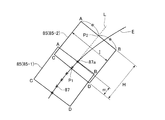
得られた複数のエッジ点87のサンプリング値に例えば最小2乗法により、近似直線を当てはめる(ステップS3)。いま、図8に示すように、ツール85−1により得られたエッジ点87のサンプリング値から近似直線Lが求められたとすると、この近似直線Lに沿うように、画像測定装置1は次のツール85(85-2)の位置を決定する(ステップS4)。
An approximate straight line is applied to the obtained sampling values of the plurality of edge points 87 by, for example, the least square method (step S3). Now, as shown in FIG. 8, if the approximate line L is obtained from the sampling value of the
このため、まず、現ツール85−1で求められたツールの移動方向における最も端のエッジ点87aから近似直線Lに垂線を下ろす。エッジ点87aと近似直線Lとは近接しているので、図8には上記垂線が表れていない。この垂線と近似直線Lとの交点から、近似直線Lに沿ってツール85の移動方向とは逆向きにH・m/100(但し、Hはツール85の高さ、mは予め設定された重複率(%))だけ離れた点P1とこの点P1からツール85の移動方向にHだけ離れた点P2とを求める。次に、点P1,P2で近似直線Lにそれぞれ直交する直線上で、近似直線LからそれぞれI/2(但し、Iはツール85の幅)だけ離れた点をそれぞれ新たなツール85−2の四隅の点A,B,C,Dとする。これにより、次のツール85−2の位置が決定される。
For this reason, first, a perpendicular is drawn from the
この決定された位置に、画像測定装置1により、近似直線Lに沿って一部の領域が現在のツール85−1に重なるように次の新たなツール85−2が生成されたら、画像測定装置1は前述と同様のツール85−2内のエッジ点のサンプリングと近似直線の当てはめを行いながら、順次ツール85を移動していく。そして、追跡すべきエッジEを全て追跡したら、処理を終了する(ステップS5)。
When the next new tool 85-2 is generated at the determined position by the
以上がオートトレース用のツールを用いたエッジ追跡である。これによると、測定のスタート点とエンド点を指定すれば、枠状のツール85がスタート点からエンド点まで停止することなく、エッジEを自動的に追跡する。なお、エッジ追跡のみを説明しているが、エッジ検出の処理はエッジ追跡の処理と別に実行される。例えば図8の新たなツール85−2の四隅の点A,B,C,Dの位置が演算されると、新たなツール85−2を画面上に表示する前に、現在のツール85−1でエッジEを検出し、その後、新たなツール85−2を画面上に表示するのである。
The above is edge tracking using a tool for auto tracing. According to this, when the measurement start point and end point are designated, the frame-shaped
ところで、複雑な表面形状を有するワークにオートトレース用のツールを用いると、エッジ追跡の経路を誤ることがある。これについて説明する。まず、エッジ検出されるワークWの一例について、図9〜図12を用いて説明する。図9はワークWの表面を示す平面図であり、図10は図9のX(a)-X(b)線に沿った断面図であり、図11はワークWの裏面を示す平面図であり、図12はワークWの一部の平面図である。 By the way, when a tool for auto tracing is used for a workpiece having a complicated surface shape, an edge tracking path may be wrong. This will be described. First, an example of the workpiece W whose edge is detected will be described with reference to FIGS. 9 is a plan view showing the surface of the workpiece W, FIG. 10 is a sectional view taken along line X (a) -X (b) in FIG. 9, and FIG. 11 is a plan view showing the back surface of the workpiece W. FIG. 12 is a plan view of a part of the workpiece W.
ワークWはリードフレームの金型(抜き金型)である。リード部91がフレーム部93で囲まれた構造を有する。図12は一つのリード部91の平面図である。図12の実線がリード部91のエッジEである。リード部91どうしはダイバ95で接続されている。フレーム部93及びダイバ95はリード部91に比べて厚みが小さい。リード部91どうしの間やリード部91とフレーム部93の間には穴97がある。これらの穴97はリードフレームを形成する際に打ち抜かれた部分と対応する。
The workpiece W is a lead frame die (die cut). The
図13はエッジ追跡の経路を説明する図であり、図9と対応する。スタート点99及びエンド点101を指定し、ツールによりリード部91のエッジEを自動的に追跡しながらエッジEを検出してリード部91の輪郭形状を計測している。実線矢印がエッジ追跡の正しい経路を示し、点線矢印がエッジ追跡の誤った経路を示している。
FIG. 13 is a diagram for explaining the path of edge tracking, and corresponds to FIG. The
リード部91のエッジEは、フレーム部93のエッジE1やダイバ95のエッジE2とつながっている。したがって、オートトレース用のツールを用いて、このようなワークWのエッジ検出をすると、点線矢印で示すように、誤ってエッジE1を追跡してエッジE1を検出する場合がある。このようなエッジ検出がされると、リード部91の輪郭形状の正しいデータを得ることができない。さらに、ツールがエンド点101に到達してから、改めてスタート点99からエッジEの検出をやり直さなければならず、オペレータにとって大変面倒であった。
The edge E of the
次に、本実施形態に係る画像測定装置1を用いて、リード部91のエッジEを追跡し検出する操作について、図4、図9、図11及び図14〜図19を用いて説明する。図14はエッジ検出のフローチャートである。図15〜図19は、エッジ検出時のカラービデオウィンドウ69の表示状態を示している。
Next, an operation for tracking and detecting the edge E of the
まず、オペレータは図4の照明ウィンドウ77の中からワークWの照明方式を選択する(ステップT1)。ワークの鮮明な画像を得るために、照明は重要である。ワークの照明には、主に三つの方式がある。一つは、ワークの裏面側からワークに照明光を照射する透過照明方式である。もう一つは、ワークWの表面の略真上からワークに照射光を照射する落射照明方式である。残りの一つは、所定の角度で傾斜した方向からワークに照明光を照射するリング照明方式である。
First, the operator selects an illumination method for the workpiece W from the
透過照明でワークWを照明すると、ワークWの画像に表れるワークWの形状は図11に示すような形状である。リード部91をフレーム部93やダイバ95と区別できないので、この照明方式を選択することはできない。一方、落射照明方式やリング照明方式によれば、ワークWの画像に表れるワークWの形状は図9に示すような形状となる。
When the workpiece W is illuminated with transmitted illumination, the shape of the workpiece W appearing in the image of the workpiece W is a shape as shown in FIG. Since the
落射照明方式は、比較的簡単な形状を有するワークの照明に利用されることが多い。この方式は複雑な形状を有するワークの照明に適さない。例えば、ワークが段差を有すると、段差が陰となり、段差の箇所の画像が鮮明にならない場合がある。リング照明方式によれば、斜め方向から照明するのでワークが段差を有していても、鮮明な画像を得ることができる。図9及び図10に示すように、ワークWは、リード部91とフレーム部93やリード部91とダイバ95で段差が形成されている。したがって、リング照明方式を選択する。
The epi-illumination method is often used for illumination of a workpiece having a relatively simple shape. This method is not suitable for lighting a workpiece having a complicated shape. For example, when the workpiece has a step, the step is shaded and the image of the step may not be clear. According to the ring illumination method, since the illumination is performed from an oblique direction, a clear image can be obtained even if the workpiece has a step. As shown in FIGS. 9 and 10, the workpiece W has a step formed by a
そして、図15に示すように、オペレータは、リード部(測定箇所の一例)91の画像上の測定のスタート点99にツール85を置く(ステップT3)。この操作は、図6を用いて既に説明した。
Then, as shown in FIG. 15, the operator places the
次に、図16に示すように、オペレータはリード部91の画像上で中継点103を指示する(ステップT5)。中継点の指示を具体的に説明すると、オペレータが図4に示すメニューバー71の「測定」の中から「中継点」を選択すると、黒丸状のマークがワークWの画像に重ねてカラービデオウィンドウ69に表示される。そして、オペレータはマウスを操作して、上記黒丸状のマークを中継点103にしたい箇所に置く。これにより、カラービデオウィンドウ69に表示された測定箇所の画像上でエッジ検出の区間(スタート点99から中継点103)を定める中継点103が指示されたことになる。中継点103は、リード部91のエッジEがフレーム部93のエッジE1と接触している箇所である。これにより、ツール85が誤ってエッジE1を追跡してエッジE1を検出するのを防止できる。
Next, as shown in FIG. 16, the operator designates the
中継点103を置いてからオペレータがエッジ検出の指令をすると、ツール85はスタート点99から中継点103までの区間のエッジEを自動的に追跡し、エッジEを検出する(ステップT7)。図17に示すように、ツール85は中継点103で自動的に停止する。
When the operator issues an edge detection command after placing the
そして、図18に示すように、オペレータは中継点105を新たに指示する(ステップT9)。中継点105はエッジEが急激に曲がる箇所である。この箇所はツール85がエッジEを見失う可能性があるからである。中継点105の指示は中継点103の場合と同様である。
Then, as shown in FIG. 18, the operator newly designates the relay point 105 (step T9). The
図19に示すように、オペレータがエッジ検出の指令をすると、ツール85は中継点103から中継点105までの区間(つまり、新たに指示された中継点105により定められた区間)のエッジEを自動的に追跡し、エッジEを検出する(ステップT11)。ツール85は中継点105で自動的に停止する。この後は同様に中継点を指定しながら(ステップT13)、エッジEの検出を実行する。つまり、中継点が指示される毎にその中継点により定められた区間のエッジを、ツール85により追跡させてその区間のエッジを検出する。
As shown in FIG. 19, when the operator gives an edge detection command, the
ツール85がエンド点に到達する前にいずれかの中継点に到達した時点で、何らかの理由により、エッジ検出を終了したい場合、オペレータは、中継点を新たに指示することなく、エッジ検出終了の指令を画像測定装置1に与える(ステップT9,T13)。
When it is desired to end edge detection for some reason when the
以上説明したように、本実施形態によれば、リード部91のエッジEが他のエッジE1,E2と接触している箇所やエッジEが急激に曲がる箇所等に中継点を置いている。この中継点により定められた区間のエッジを、ツール85により追跡させてその区間のエッジを検出している。これにより、エッジEの追跡の精度が上がるので、エッジEの追跡の誤りが原因となるエッジEの検出の誤りを少なくできる。
As described above, according to the present embodiment, the relay point is placed at a location where the edge E of the
また、本実施形態によれば、仮にエッジEの追跡の経路を誤った場合、この誤った中継点間からエッジEの検出を再開すればよい。例えば、中継点103と中継点105の間でエッジEの追跡の経路を誤った場合、中継点103からエッジEの追跡を再開すればよい。よって、エッジ検出のやり直しの手間を少なくできる。
Further, according to the present embodiment, if the tracking path of the edge E is erroneous, the detection of the edge E may be restarted from between the erroneous relay points. For example, when the tracking path of the edge E between the
なお、この例では測定箇所であるリード部91が1画面内に表れている。測定箇所が1画面内に表れない場合、測定箇所の1画面内に表示された部分のエッジ検出をする。そして、図1に示す測定テーブル9を移動させることにより、測定箇所の別の部分を1画面内に表示させ、この部分についてエッジ検出をする。これを繰りかえして、測定箇所の全体のエッジを検出する。
In this example, a
ところで、測定箇所のエッジに障害物(ネジ穴、突起物等)が存在する場合、たとえ中継点を指定しても、エッジの追跡の経路を誤る場合がある。これについて説明する。図20及び図21はワークの測定箇所のエッジEにネジ穴111が存在している場合の画像を示す図である。エッジEがネジ穴111のエッジE3と接触する箇所に中継点113,115を設けても、ツール85は中継点間においてネジ穴111のエッジE3を追跡し、エッジE3を検出する。したがって、測定箇所の正確な輪郭形状を得ることができない。
By the way, when there are obstacles (screw holes, protrusions, etc.) at the edge of the measurement location, even if a relay point is specified, the edge tracking path may be wrong. This will be described. 20 and 21 are diagrams showing images when the
本実施形態では、指示された中継点113,115により定められた区間のエッジ追跡を省略することにより、測定箇所のエッジEにネジ穴111等の障害物が存在しても、それらの影響を受けないようにすることができる。具体的に説明すると、中継点113までのエッジEの検出を終了してから、オペレータが図4に示すメニューバー71の「測定」から「スキップ」を選択すると、黒丸状のマークがワークWの画像に重ねてカラービデオウィンドウに表示される。そして、オペレータはマウスを操作して、上記黒丸状のマークを中継点115の箇所に置く。オペレータがスキップを指令すると、中継点113,115により定められた区間のエッジ追跡が省略される。
In the present embodiment, by omitting the edge tracking of the section defined by the designated relay points 113 and 115, even if an obstacle such as the
この省略により、中継点113,115間のエッジが検出されないので、エッジ点の補完処理をする。図22はこの処理を説明する図である。ツールにより所定のピッチでエッジEのエッジ点117が抽出される。中継点113,115の区間も、これと同じピッチでエッジ点119を抽出したものとされる。これらのエッジ点117,119の近似直線を最小2乗法により求め、エッジEとする。これにより、エッジ追跡を省略した区間が存在することによる測定誤差を小さくすることができる。 By this omission, the edge between the relay points 113 and 115 is not detected, so that the edge point complement processing is performed. FIG. 22 is a diagram for explaining this process. Edge points 117 of the edge E are extracted at a predetermined pitch by the tool. The intervals between the relay points 113 and 115 are also extracted from the edge points 119 at the same pitch. An approximate straight line of these edge points 117 and 119 is obtained by the method of least squares and is defined as edge E. Thereby, the measurement error due to the existence of a section in which edge tracking is omitted can be reduced.
最後に、本実施形態に係る画像測定装置1の機能ブロックの一例について、図3、図4及び図23を用いて説明する。図23は、画像測定装置1の機能ブロック図である。入力部121は、ワークの測定箇所を撮像する撮像部123と測定箇所の画像上で中継点を指示する指示部125で構成される。具体的には、撮像部123はCCDカメラ19であり、指示部125は入力装置であるマウス35やキーボード31である。
Finally, an example of functional blocks of the
記憶部127は、撮像部123で撮像されたワークの多値画像データを記憶したり、エッジ検出の演算をする際のワーク領域を提供したりする等の機能を有する。記憶部127は、図3のプログラムメモリ43、ワークメモリ45及び多値画像メモリ47と対応し、RAMやROMで実現される。
The
処理部129は、画像処理部131及び検出部133を含む。処理部129の機能は、図3のCPU41で実現される。画像処理部131は、図4のカラービデオウィンドウ69に表示する画像の生成、画像上に置かれるツールの設定等の各種処理をする。検出部133はワークの測定箇所のエッジを検出する。この検出結果に基づいて、グラフィックウィンドウ79や測定結果ウィンドウ81に表示する内容(ワークの測定箇所の輪郭形状)を求める処理等が実行される。
The
検出部133には、追跡部135とスキップ部137が含まれる。追跡部135は、図14〜図19で説明したように、中継点が指示される毎にその中継点により定められた区間の測定箇所のエッジをツールにより自動的に追跡させる処理を実行する。スキップ部137は図20〜図22で説明したように、指示された中継点により定められた区間のエッジ追跡を省略する処理を実行する。
The
表示部139は、具体的に図3のCRT37である。表示部139としては、他に、液晶ディスプレイがある。
The
なお、本実施形態に係る画像測定装置は、CNC(Computer Numerical Control)型、マニュアル操作型のいずれも適用することができる。CNC型では、測定テーブル移動を含めて自動で測定が実行される。これに対して、マニュアル操作型では、オペレータの手動による操作によって測定テーブルが移動される。 The image measuring apparatus according to the present embodiment can be applied to either a CNC (Computer Numerical Control) type or a manual operation type. In the CNC type, measurement is automatically performed including measurement table movement. In contrast, in the manual operation type, the measurement table is moved by an operator's manual operation.
1・・・画像測定装置、3・・・三次元測定機、5・・・コンピュータシステム、7・・・架台、9・・・測定テーブル、11,13・・・支持アーム、15・・・X軸ガイド、17・・・撮像ユニット、19・・・CCDカメラ、21・・・対物レンズ、23・・・照明装置、25・・・発光ダイオード、27・・・ケース、29・・・コンピュータ、31・・・キーボード、33・・・ジョイステックボックス、35・・・マウス、37・・・CRT、39・・・プリンタ、41・・・CPU、43・・・プログラムメモリ、45・・・ワークメモリ、47・・・多値画像メモリ、49・・・表示制御IC、51・・・照明制御IC、53・・・バス、55・・・インターフェース、57・・・X軸エンコーダ、59・・・Y軸エンコーダ、61・・・Z軸エンコーダ、63,65・・・インターフェース、67・・・CRTの画面、69・・・カラービデオウィンドウ、71・・・メニュウーバー、73・・・カウンタウィンドウ,75・・・ナビゲータウィンドウ、77・・・照明ウィンドウ、79・・・グラフィックウィンドウ、81・・・測定結果ウィンドウ、83・・・ステータスバー、85・・・ツール(オートトレース用のツール)、87・・・エッジ点、91・・・リード部、93・・・フレーム部、95・・・ダイバ、97・・・穴、99・・・スタート点、101・・・エンド点、103,105・・・中継点、111・・・ネジ穴、113,115・・・中継点、117,119・・・エッジ点、121・・・入力部、123・・・撮像部、125・・・指示部、127・・・記憶部、129・・・処理部、131・・・画像処理部、133・・・検出部、135・・・追跡部、137・・・スキップ部、139・・・表示部、W・・・ワーク、E・・・リード部のエッジ、E1・・・フレーム部のエッジ、E2・・・ダイバのエッジ、E3・・・ネジ穴のエッジ
DESCRIPTION OF
Claims (3)
前記表示手段に表示された前記測定箇所の画像上でエッジ検出の区間を定める中継点を指示する指示手段と、
中継点が指示される毎にその中継点により定められた区間のエッジを、前記ツールにより追跡させてその区間のエッジを検出する検出手段と、を備え、
前記検出手段は、前記ツール内の前記エッジの画像情報から前記ツール内の複数のエッジ点を抽出し、得られた複数のエッジ点に近似直線を当てはめると共に、この近似直線に沿って一部の領域が現在のツールに重なるように次の新たなツールを生成する、エッジ追跡手段を含む
ことを特徴とする画像測定装置。 Display means for displaying an image of a measurement location of a workpiece and a frame-shaped tool for detecting an edge of the measurement location;
Instructing means for instructing a relay point for defining an edge detection section on the image of the measurement location displayed on the display means;
Detecting means for detecting the edge of the section by tracking the edge of the section defined by the relay point every time the relay point is indicated by the tool,
The detection means extracts a plurality of edge points in the tool from the image information of the edge in the tool, applies an approximate straight line to the obtained plurality of edge points, and a part of the approximate straight line along the approximate straight line An image measuring apparatus comprising edge tracking means for generating a next new tool such that a region overlaps a current tool.
ことを特徴とする請求項1記載の画像測定装置。 The image measurement apparatus according to claim 1, further comprising skip means for omitting edge tracking in a section defined by the instructed relay point.
ことを特徴とする請求項2記載の画像測定装置。 The image measuring apparatus according to claim 2, wherein the detection unit performs an edge detection process on the section in which the edge tracking is omitted, assuming that edge points are extracted at the same pitch as the preceding and succeeding sections.
Priority Applications (1)
| Application Number | Priority Date | Filing Date | Title |
|---|---|---|---|
| JP2005039002A JP2006226760A (en) | 2005-02-16 | 2005-02-16 | Image measuring apparatus |
Applications Claiming Priority (1)
| Application Number | Priority Date | Filing Date | Title |
|---|---|---|---|
| JP2005039002A JP2006226760A (en) | 2005-02-16 | 2005-02-16 | Image measuring apparatus |
Publications (1)
| Publication Number | Publication Date |
|---|---|
| JP2006226760A true JP2006226760A (en) | 2006-08-31 |
Family
ID=36988275
Family Applications (1)
| Application Number | Title | Priority Date | Filing Date |
|---|---|---|---|
| JP2005039002A Pending JP2006226760A (en) | 2005-02-16 | 2005-02-16 | Image measuring apparatus |
Country Status (1)
| Country | Link |
|---|---|
| JP (1) | JP2006226760A (en) |
Cited By (1)
| Publication number | Priority date | Publication date | Assignee | Title |
|---|---|---|---|---|
| JP2012088162A (en) * | 2010-10-19 | 2012-05-10 | Mitsutoyo Corp | Image measuring device and drive controlling method |
-
2005
- 2005-02-16 JP JP2005039002A patent/JP2006226760A/en active Pending
Cited By (1)
| Publication number | Priority date | Publication date | Assignee | Title |
|---|---|---|---|---|
| JP2012088162A (en) * | 2010-10-19 | 2012-05-10 | Mitsutoyo Corp | Image measuring device and drive controlling method |
Similar Documents
| Publication | Publication Date | Title |
|---|---|---|
| US8010224B2 (en) | Automatic cutting device and production method for beveled product | |
| US6968080B2 (en) | Method and apparatus for generating part programs for use in image-measuring instruments, and image-measuring instrument and method of displaying measured results therefrom | |
| JP6845873B2 (en) | Method and machine tool to determine XYZ reference coordinates of workpiece | |
| US11780080B2 (en) | Robot teaching with scans and geometries | |
| JPH11118444A (en) | Non-contact image measuring system | |
| JP7674464B2 (en) | Simulation device using 3D position information obtained from the output of a visual sensor | |
| US20230096477A1 (en) | Information processing device, machining system, machine tool, and program | |
| JP6579682B2 (en) | Image measuring device | |
| US10027885B2 (en) | Image measuring apparatus | |
| JP2006226760A (en) | Image measuring apparatus | |
| CN116847958A (en) | Method and apparatus for adjusting robot path for processing workpieces | |
| JPH09259289A (en) | Edge posture recognition type measuring method and apparatus | |
| JP4074202B2 (en) | Image measuring apparatus and program for generating edge tracking measurement program | |
| JPH11351824A (en) | Coordinate system correcting method and image measuring instrument | |
| JP3853507B2 (en) | Line width measuring method and apparatus | |
| JP4053642B2 (en) | Coordinate system setting method and image measuring apparatus | |
| JP2937918B2 (en) | Image measuring device | |
| JP2519444B2 (en) | Work line tracking device | |
| JPH08292015A (en) | Noncontact image measuring system and edge tracing measuring method | |
| JPH11237221A (en) | Image measuring method and equipment | |
| JP3580392B2 (en) | Moving mark type measuring method and apparatus | |
| JP4812477B2 (en) | Image measurement device part program generation device, image measurement device part program generation method, and image measurement device part program generation program | |
| JP4476761B2 (en) | Image measuring device | |
| JP2012088162A (en) | Image measuring device and drive controlling method | |
| JP6687229B2 (en) | Image measuring device |