JP2006192607A - Method and device for preparing frame data, frame data-preparation program, and method and device for drawing - Google Patents
Method and device for preparing frame data, frame data-preparation program, and method and device for drawing Download PDFInfo
- Publication number
- JP2006192607A JP2006192607A JP2005004004A JP2005004004A JP2006192607A JP 2006192607 A JP2006192607 A JP 2006192607A JP 2005004004 A JP2005004004 A JP 2005004004A JP 2005004004 A JP2005004004 A JP 2005004004A JP 2006192607 A JP2006192607 A JP 2006192607A
- Authority
- JP
- Japan
- Prior art keywords
- data
- frame data
- scanning direction
- image data
- frame
- Prior art date
- Legal status (The legal status is an assumption and is not a legal conclusion. Google has not performed a legal analysis and makes no representation as to the accuracy of the status listed.)
- Pending
Links
Images


Classifications
-
- H—ELECTRICITY
- H04—ELECTRIC COMMUNICATION TECHNIQUE
- H04N—PICTORIAL COMMUNICATION, e.g. TELEVISION
- H04N1/00—Scanning, transmission or reproduction of documents or the like, e.g. facsimile transmission; Details thereof
- H04N1/04—Scanning arrangements, i.e. arrangements for the displacement of active reading or reproducing elements relative to the original or reproducing medium, or vice versa
- H04N1/10—Scanning arrangements, i.e. arrangements for the displacement of active reading or reproducing elements relative to the original or reproducing medium, or vice versa using flat picture-bearing surfaces
- H04N1/1008—Scanning arrangements, i.e. arrangements for the displacement of active reading or reproducing elements relative to the original or reproducing medium, or vice versa using flat picture-bearing surfaces with sub-scanning by translatory movement of the picture-bearing surface
-
- B—PERFORMING OPERATIONS; TRANSPORTING
- B41—PRINTING; LINING MACHINES; TYPEWRITERS; STAMPS
- B41J—TYPEWRITERS; SELECTIVE PRINTING MECHANISMS, i.e. MECHANISMS PRINTING OTHERWISE THAN FROM A FORME; CORRECTION OF TYPOGRAPHICAL ERRORS
- B41J2/00—Typewriters or selective printing mechanisms characterised by the printing or marking process for which they are designed
- B41J2/435—Typewriters or selective printing mechanisms characterised by the printing or marking process for which they are designed characterised by selective application of radiation to a printing material or impression-transfer material
- B41J2/447—Typewriters or selective printing mechanisms characterised by the printing or marking process for which they are designed characterised by selective application of radiation to a printing material or impression-transfer material using arrays of radiation sources
- B41J2/46—Typewriters or selective printing mechanisms characterised by the printing or marking process for which they are designed characterised by selective application of radiation to a printing material or impression-transfer material using arrays of radiation sources characterised by using glass fibres
-
- B—PERFORMING OPERATIONS; TRANSPORTING
- B41—PRINTING; LINING MACHINES; TYPEWRITERS; STAMPS
- B41J—TYPEWRITERS; SELECTIVE PRINTING MECHANISMS, i.e. MECHANISMS PRINTING OTHERWISE THAN FROM A FORME; CORRECTION OF TYPOGRAPHICAL ERRORS
- B41J21/00—Column, tabular or like printing arrangements; Means for centralising short lines
-
- B—PERFORMING OPERATIONS; TRANSPORTING
- B41—PRINTING; LINING MACHINES; TYPEWRITERS; STAMPS
- B41J—TYPEWRITERS; SELECTIVE PRINTING MECHANISMS, i.e. MECHANISMS PRINTING OTHERWISE THAN FROM A FORME; CORRECTION OF TYPOGRAPHICAL ERRORS
- B41J5/00—Devices or arrangements for controlling character selection
- B41J5/30—Character or syllable selection controlled by recorded information
-
- H—ELECTRICITY
- H04—ELECTRIC COMMUNICATION TECHNIQUE
- H04N—PICTORIAL COMMUNICATION, e.g. TELEVISION
- H04N1/00—Scanning, transmission or reproduction of documents or the like, e.g. facsimile transmission; Details thereof
- H04N1/04—Scanning arrangements, i.e. arrangements for the displacement of active reading or reproducing elements relative to the original or reproducing medium, or vice versa
- H04N1/047—Detection, control or error compensation of scanning velocity or position
-
- H—ELECTRICITY
- H04—ELECTRIC COMMUNICATION TECHNIQUE
- H04N—PICTORIAL COMMUNICATION, e.g. TELEVISION
- H04N1/00—Scanning, transmission or reproduction of documents or the like, e.g. facsimile transmission; Details thereof
- H04N1/04—Scanning arrangements, i.e. arrangements for the displacement of active reading or reproducing elements relative to the original or reproducing medium, or vice versa
- H04N1/19—Scanning arrangements, i.e. arrangements for the displacement of active reading or reproducing elements relative to the original or reproducing medium, or vice versa using multi-element arrays
- H04N1/195—Scanning arrangements, i.e. arrangements for the displacement of active reading or reproducing elements relative to the original or reproducing medium, or vice versa using multi-element arrays the array comprising a two-dimensional [2D] array
-
- H—ELECTRICITY
- H04—ELECTRIC COMMUNICATION TECHNIQUE
- H04N—PICTORIAL COMMUNICATION, e.g. TELEVISION
- H04N1/00—Scanning, transmission or reproduction of documents or the like, e.g. facsimile transmission; Details thereof
- H04N1/23—Reproducing arrangements
-
- H—ELECTRICITY
- H04—ELECTRIC COMMUNICATION TECHNIQUE
- H04N—PICTORIAL COMMUNICATION, e.g. TELEVISION
- H04N2201/00—Indexing scheme relating to scanning, transmission or reproduction of documents or the like, and to details thereof
- H04N2201/04—Scanning arrangements
- H04N2201/047—Detection, control or error compensation of scanning velocity or position
- H04N2201/04753—Control or error compensation of scanning position or velocity
- H04N2201/04758—Control or error compensation of scanning position or velocity by controlling the position of the scanned image area
- H04N2201/04767—Control or error compensation of scanning position or velocity by controlling the position of the scanned image area by controlling the timing of the signals, e.g. by controlling the frequency o phase of the pixel clock
Landscapes
- Engineering & Computer Science (AREA)
- Multimedia (AREA)
- Signal Processing (AREA)
- Health & Medical Sciences (AREA)
- General Health & Medical Sciences (AREA)
- Toxicology (AREA)
- Exposure And Positioning Against Photoresist Photosensitive Materials (AREA)
- Image Processing (AREA)
- Facsimile Scanning Arrangements (AREA)
- Holo Graphy (AREA)
- Printers Or Recording Devices Using Electromagnetic And Radiation Means (AREA)
- Record Information Processing For Printing (AREA)
- Fax Reproducing Arrangements (AREA)
Abstract
Description
本発明は、空間光変調素子などの描画点形成部を、描画面に対して所定の走査方向に相対的に移動させて画像を形成する際に用いられるフレームデータを作成するフレームデータ作成方法および装置並びにプログラム、そのフレームデータ作成方法および装置並びにプログラムを用いて作成された取得されたフレームデータを用いて描画を行う描画方法および装置に関するものである。 The present invention relates to a frame data creation method for creating frame data used when forming an image by moving a drawing point forming unit such as a spatial light modulator relative to a drawing surface in a predetermined scanning direction, and The present invention relates to an apparatus, a program, a frame data creation method and apparatus thereof, and a drawing method and apparatus for performing drawing using acquired frame data created using the program.
従来、画像データが表す所望の2次元パターンを描画面上に形成する描画装置が種々知られている。 Conventionally, various drawing apparatuses for forming a desired two-dimensional pattern represented by image data on a drawing surface are known.
上記のような描画装置として、たとえば、デジタル・マイクロミラー・デバイス(以下、DMDという)等の空間光変調素子を利用し、画像データに応じて空間光変調素子により光ビームを変調して露光を行う露光装置が種々提案されている。DMDは、シリコン等の半導体基板上のメモリセル(SRAMアレイ)に、微小なマイクロミラーが2次元状に多数配置されて構成されたものである。そして、メモリセルに蓄積される電荷による静電気力を制御することによってマイクロミラーを傾斜させて反射面の角度を変化させることができ、この反射面の角度変化により所望の位置に描画点を形成して画像を形成することができるものである。 As a drawing apparatus as described above, for example, a spatial light modulator such as a digital micromirror device (hereinafter referred to as DMD) is used, and exposure is performed by modulating a light beam by the spatial light modulator according to image data. Various exposure apparatuses have been proposed. The DMD is configured by arranging a large number of minute micromirrors two-dimensionally in a memory cell (SRAM array) on a semiconductor substrate such as silicon. Then, by controlling the electrostatic force due to the electric charge accumulated in the memory cell, the angle of the reflecting surface can be changed by tilting the micromirror, and a drawing point is formed at a desired position by changing the angle of the reflecting surface. Thus, an image can be formed.
そして、上記のようなDMDを用いた露光装置としては、たとえば、DMDを露光面に対して所定の走査方向に相対的に移動させるとともに、その走査方向への移動に応じてDMDのメモリセルに多数のマイクロミラーに対応した多数の描画点データからなるフレームデータを入力し、DMDのマイクロミラーに対応した描画点群を時系列に順次形成することにより所望の画像を露光面に形成する露光装置が提案されている。 As an exposure apparatus using the DMD as described above, for example, the DMD is moved relative to the exposure surface in a predetermined scanning direction, and the memory cell of the DMD is moved according to the movement in the scanning direction. An exposure apparatus for inputting a frame data composed of a large number of drawing point data corresponding to a large number of micromirrors, and forming a desired image on an exposure surface by sequentially forming drawing point groups corresponding to DMD micromirrors in time series. Has been proposed.
また、一般に、DMDのマイクロミラーは、各行の並び方向と各列の並び方向とが直交するように配列されている。そして、このようなDMDを走査方向に対して所定の角度だけ傾けて上記のような露光を行うことによって、マイクロミラーにより走査される走査線の間隔を密にし、露光面上に形成される画像の解像度を向上させた露光装置も提案されている(特許文献1参照)。 In general, the DMD micromirrors are arranged so that the arrangement direction of each row and the arrangement direction of each column are orthogonal to each other. An image formed on the exposure surface is formed by inclining such a DMD by a predetermined angle with respect to the scanning direction and performing exposure as described above, thereby narrowing the interval between the scanning lines scanned by the micromirror. An exposure apparatus with improved resolution is also proposed (see Patent Document 1).
ここで、上記のような露光装置を用いて露光を行う際には、上述したようにDMDの走査方向への相対的な移動に応じてフレームデータをDMDに順次入力する必要がある。したがって、露光の前に予め露光面に対するDMDの位置に対応した複数のフレームデータを作成しておく必要がある。 Here, when performing exposure using the exposure apparatus as described above, it is necessary to sequentially input frame data to the DMD in accordance with the relative movement of the DMD in the scanning direction as described above. Therefore, it is necessary to create a plurality of frame data corresponding to the position of the DMD with respect to the exposure surface before exposure.
そして、上記のようなフレームデータを作成する際には、たとえば、露光面に露光されるべき画像を表す画像データをDRAMなどのメモリに一旦記憶し、露光面に対するDMDの各位置について、DMDの各マイクロミラーに対応する画素データを上記メモリから順次読み出すことによってDMDの各マイクロミラーに入力される各描画点データを取得し、その取得された描画点データにより各フレームデータを作成していた。
しかしながら、図18に示すように、上記画像データ1は、DMDの走査方向に対応する副走査方向およびその副走査方向に直交する主走査方向に画素データ5が2次元状に配置されたものであるため、たとえば、上記のようにDMDを走査方向に対して所定の角度だけ傾けた露光装置におけるフレームデータを作成する場合において、各マイクロミラーに対応する画素データを順次読み出すようにしたのでは、たとえば、図18の主走査方向に配列された画素データが、上記メモリにそのアドレスが連続する方向に記憶されているような場合には、各マイクロミラーに対応する画素データが記憶されたアドレスは、メモリを制御する制御手段からみたメモリのアドレス空間において離散的に配置されており、このような配置のアドレスに1つ1つアクセスしながら画素データを読み出すのはメモリの制御上、非常に時間がかかり、全てのフレームデータを取得するのに非常に時間がかかってしまう。
However, as shown in FIG. 18, the
本発明は、上記事情に鑑み、上記のようなフレームデータをより高速に作成することができるフレームデータ作成方法および装置並びにプログラムを提供するとともに、上記フレームデータ作成方法等を利用した描画方法および装置を提供することを目的とするものである。 In view of the above circumstances, the present invention provides a frame data creation method and apparatus and program capable of creating frame data as described above at higher speed, and a drawing method and apparatus using the frame data creation method and the like. Is intended to provide.
本発明のフレームデータ作成方法は、描画面上に描画点を形成する複数の描画素子が、一列に配置された描画素子群が複数平行に配列された描画点形成部を、描画面に対し、描画点形成部の描画素子群の配列方向と所定の傾斜角θ(ただし、0°<θ<90°)をなす走査方向に相対的に移動させるとともに、その走査方向への移動に応じて描画素子に対応した複数の描画点データからなるフレームデータを描画点形成部に順次入力して描画点群を時系列に順次形成することにより複数の描画点が2次元状に配置された画像を描画面上に形成する際に用いられるフレームデータを作成するフレームデータ作成方法であって、上記走査方向に対応する副走査方向およびその副走査方向に直交する主走査方向に描画点データに対応する画素データが2次元状に配置された、上記画像に応じた画像データに基づいて、上記複数の描画点データを取得してフレームデータを作成するフレームデータ作成方法において、画像データにおける描画素子群に対応する画素データが主走査方向に並ぶように画像データに変形処理を施し、その変形処理済画像データに基づいてフレームデータを作成することを特徴とする。 In the frame data creation method of the present invention, a drawing point forming unit in which a plurality of drawing elements forming a drawing point on a drawing surface is arranged in parallel with a plurality of drawing element groups arranged in a row is arranged with respect to the drawing surface. The drawing point forming unit is moved relative to the scanning direction that forms a predetermined inclination angle θ (where 0 ° <θ <90 °) with the arrangement direction of the drawing element group, and drawing is performed in accordance with the movement in the scanning direction. Frame data consisting of a plurality of drawing point data corresponding to the element is sequentially input to a drawing point forming unit, and a drawing point group is sequentially formed in time series to draw an image in which a plurality of drawing points are arranged in a two-dimensional manner. A frame data creation method for creating frame data used when forming on a surface, and a pixel corresponding to drawing point data in a sub-scanning direction corresponding to the scanning direction and a main scanning direction orthogonal to the sub-scanning direction The data is Pixel data corresponding to a drawing element group in image data in a frame data creation method for obtaining frame data by acquiring the plurality of drawing point data based on image data corresponding to the image arranged in a dimension The image data is subjected to deformation processing so that the image data are arranged in the main scanning direction, and frame data is created based on the deformation-processed image data.
また、上記フレームデータ作成方法においては、変形処理済画像データが格納される記憶手段に、その記憶手段のアドレスが連続する方向と描画素子群に対応する画素データが格納される配列方向とが一致するように画素データを格納し、その格納された画素データを記憶手段から読み出して複数の描画点データを取得するようにすることができる。 In the frame data creation method, the direction in which the addresses of the storage means are continuous and the arrangement direction in which the pixel data corresponding to the drawing element group are stored coincide with each other in the storage means in which the transformed image data is stored. Thus, pixel data can be stored, and the stored pixel data can be read from the storage means to obtain a plurality of drawing point data.
また、描画素子群に対応する各画素データを、それぞれ上記傾斜角に応じて上記副走査方向にシフトさせることによって変形処理を施すようにすることができる。 Further, each pixel data corresponding to the drawing element group can be modified by shifting the pixel data in the sub-scanning direction according to the tilt angle.
また、描画素子群の各描画素子に対応する、同じフレームデータに属する画素データが上記主走査方向に連続して配置されるように画素データを上記走査方向について並び替え、その並び替え後の変形処理済画像データに基づいてフレームデータを作成するようにすることができる。 Further, the pixel data is rearranged in the scanning direction so that pixel data belonging to the same frame data corresponding to each drawing element of the drawing element group is continuously arranged in the main scanning direction, and the deformation after the rearrangement is performed. Frame data can be created based on the processed image data.
また、画像データの解像度が描画面に描画される画像の解像度よりも低い場合において、上記並び替え後の変形処理済画像データの各画素データを複数回用いて描画素子に対応する描画点データを生成し、その生成された描画点データを用いてフレームデータを作成するようにすることができる。 Further, when the resolution of the image data is lower than the resolution of the image drawn on the drawing surface, the drawing point data corresponding to the drawing element is obtained by using each pixel data of the transformed image data after the rearrangement a plurality of times. It is possible to generate the frame data using the generated drawing point data.
また、描画点形成部を上記配列方向について複数の分割領域に分割し、その複数の分割領域により多重描画を行う場合において、各分割領域に対応する並び替え後の変形処理済画像データを、多重描画の順に応じてそれぞれ上記主走査方向にシフトし、そのシフトされた並び替え後の変形処理済画像データに基づいてフレームデータを作成するようにすることができる。 In addition, when the drawing point forming unit is divided into a plurality of divided areas in the arrangement direction and multiple drawing is performed using the divided areas, the rearranged modified image data corresponding to each divided area is multiplexed. It is possible to shift in the main scanning direction according to the order of drawing and to generate frame data based on the shifted rearranged image data after rearrangement.
本発明の描画方法は、上記フレームデータ作成方法を用いて各フレームデータを取得し、描画点形成部を描画面に対して走査方向に相対的に移動させるとともに、その走査方向への移動に応じて描画点形成部に順次各フレームデータを入力して描画点群を時系列に形成し、描画面上に上記画像を形成することを特徴とする。 The drawing method of the present invention acquires each frame data using the above frame data creation method, moves the drawing point forming portion relative to the drawing surface in the scanning direction, and responds to the movement in the scanning direction. Then, each frame data is sequentially input to the drawing point forming unit to form a drawing point group in time series, and the image is formed on the drawing surface.
本発明のフレームデータ作成装置は、描画面上に描画点を形成する複数の描画素子が一列に配置された描画素子群が、複数平行に配列された描画点形成部を、描画面に対し、描画点形成部の描画素子群の配列方向と所定の傾斜角θ(ただし、0°<θ<90°)をなす走査方向に相対的に移動させるとともに、その走査方向への移動に応じて描画素子に対応した複数の描画点データからなるフレームデータを描画点形成部に順次入力して描画点群を時系列に順次形成することにより複数の描画点が2次元状に配置された画像を描画面上に形成する際に用いられるフレームデータを作成するフレームデータ作成装置であって、上記走査方向に対応する副走査方向およびその副走査方向に直交する主走査方向に描画点データに対応する画素データが2次元状に配置された、画像に応じた画像データに基づいて、上記複数の描画点データを取得してフレームデータを作成するフレームデータ作成装置において、画像データにおける描画素子群に対応する画素データが主走査方向に並ぶように画像データに変形処理を施す画像データ変形部と、画像データ変形部により変形処理の施された変形処理済画像データに基づいてフレームデータを作成するフレームデータ作成部とを備えたことを特徴とする。 The frame data creation device of the present invention includes a drawing point forming unit in which a plurality of drawing element groups in which a plurality of drawing elements forming drawing points are arranged in a line on a drawing surface are arranged in parallel with respect to the drawing surface. The drawing point forming unit is moved relative to the scanning direction that forms a predetermined inclination angle θ (where 0 ° <θ <90 °) with the arrangement direction of the drawing element group, and drawing is performed in accordance with the movement in the scanning direction. Frame data consisting of a plurality of drawing point data corresponding to the element is sequentially input to a drawing point forming unit, and a drawing point group is sequentially formed in time series to draw an image in which a plurality of drawing points are arranged in a two-dimensional manner. A frame data creation device for creating frame data used when forming on a surface, and a pixel corresponding to drawing point data in a sub-scanning direction corresponding to the scanning direction and a main scanning direction orthogonal to the sub-scanning direction The data is In a frame data creation device that creates frame data by acquiring a plurality of drawing point data based on image data corresponding to an image arranged in a dimension, pixel data corresponding to a drawing element group in the image data is An image data deforming unit that performs deformation processing on image data so as to be arranged in the main scanning direction, and a frame data creating unit that generates frame data based on the deformed image data subjected to the deformation processing by the image data deforming unit. It is characterized by having.
また、上記フレームデータ作成装置においては、変形処理済画像データが格納される記憶手段と、記憶手段のアドレスが連続する方向と描画素子群に対応する画素データが格納される配列方向とが一致するように画素データを格納する記憶制御手段とをさらに備えるようにし、フレームデータ作成部を、記憶手段に格納された画素データを記憶手段から読み出して複数の描画点データを取得するものとすることができる。 In the frame data creation device, the storage means for storing the transformed image data, the direction in which the addresses of the storage means are continuous, and the arrangement direction in which the pixel data corresponding to the drawing element group are stored match. And a storage control means for storing the pixel data as described above, and the frame data creation section reads out the pixel data stored in the storage means from the storage means and acquires a plurality of drawing point data. it can.
また、画像データ変形部を、描画素子群に対応する各画素データを、それぞれ傾斜角に応じて上記副走査方向にシフトさせることによって変形処理を施すものとすることができる。 Further, the image data deforming unit may perform the deformation process by shifting each pixel data corresponding to the drawing element group in the sub-scanning direction according to the inclination angle.
また、描画素子群の各描画素子に対応する、同じフレームデータに属する画素データが上記主走査方向に連続して配置されるように画素データを上記走査方向について並び替える画素データ並替部をさらに備えるものとし、フレームデータ作成部を、画素データ並替部によって並び替えられた後の変形処理済画像データに基づいてフレームデータを作成するものとすることができる。 A pixel data rearrangement unit that rearranges the pixel data in the scanning direction so that the pixel data belonging to the same frame data corresponding to the drawing elements in the drawing element group is continuously arranged in the main scanning direction; The frame data creation unit may create frame data based on the transformed image data after being rearranged by the pixel data rearrangement unit.
また、画像データの解像度が描画面に描画される画像の解像度よりも低い場合において、フレームデータ作成部を、上記並び替えられた後の変形処理済画像データの各画素データを複数回用いて描画素子に対応する描画点データを生成し、その生成された描画点データを用いてフレームデータを作成するものとすることができる。 In addition, when the resolution of the image data is lower than the resolution of the image drawn on the drawing surface, the frame data creation unit draws using each pixel data of the transformed image data after the rearrangement a plurality of times. It is possible to generate drawing point data corresponding to the element and create frame data using the generated drawing point data.
また、描画点形成部を上記配列方向について複数の分割領域に分割し、その複数の分割領域により多重描画を行う場合において、フレームデータ作成部を、各分割領域に対応する変形処理済画像データを、多重描画の順に応じてそれぞれ上記主走査方向にシフトし、そのシフトされた変形処理済画像データに基づいてフレームデータを作成するものとすることができる。 In addition, when the drawing point forming unit is divided into a plurality of divided regions in the arrangement direction and multiple drawing is performed by the plurality of divided regions, the frame data creating unit displays the modified image data corresponding to each divided region. In addition, it is possible to shift in the main scanning direction in accordance with the order of multiple drawing, and to create frame data based on the shifted transformed image data.
本発明の描画装置は、上記フレームデータ作成装置と、入力されたフレームデータに基づいて複数の描画点からなる描画点郡を描画面上に形成する描画点形成部と、描画点形成部を描画面に対して上記走査方向に相対的に移動させる移動手段と、移動手段による走査方向への移動に応じてフレームデータ作成装置において作成されたフレームデータを描画点形成部に順次入力し、描画点形成部に描画点群を時系列に順次形成させて複数の描画点が2次元状に配置された画像を描画面上に形成させる画像形成制御部とを備えたことを特徴とする。 The drawing apparatus according to the present invention is configured to draw the drawing point forming unit, the drawing point forming unit that forms a drawing point group composed of a plurality of drawing points on the drawing surface based on the input frame data, and the drawing point forming unit. A moving unit that moves relative to the surface in the scanning direction, and frame data created by the frame data creation device in accordance with the movement in the scanning direction by the moving unit are sequentially input to the drawing point forming unit, and the drawing point And an image formation control unit that sequentially forms a drawing point group in a time series in the forming unit and forms an image in which a plurality of drawing points are arranged two-dimensionally on a drawing surface.
本発明のフレームデータ作成プログラムは、描画面上に描画点を形成する複数の描画素子が一列に配置された描画素子群が、複数平行に配列された描画点形成部を、描画面に対し、描画点形成部の描画素子群の配列方向と所定の傾斜角θ(ただし、0°<θ<90°)をなす走査方向に相対的に移動させるとともに、その走査方向への移動に応じて描画素子に対応した複数の描画点データからなるフレームデータを描画点形成部に順次入力して描画点群を時系列に順次形成することにより複数の描画点が2次元状に配置された画像を描画面上に形成する際に用いられるフレームデータを作成する手順をコンピュータに実行させるフレームデータ作成プログラムであって、上記走査方向に対応する副走査方向およびその副走査方向に直交する主走査方向に描画点データに対応する画素データが2次元状に配置された、画像に応じた画像データに基づいて、上記複数の描画点データを取得してフレームデータを作成する手順をコンピュータに実行させるフレームデータ作成プログラムにおいて、画像データにおける描画素子群に対応する画素データが主走査方向に並ぶように画像データに変形処理を施す手順と、変形処理済画像データに基づいてフレームデータを作成する手順とをコンピュータに実行させることを特徴とする。 The frame data creation program according to the present invention includes a drawing point forming unit in which a plurality of drawing element groups in which a plurality of drawing elements forming drawing points are arranged in a line on the drawing surface are arranged in parallel with respect to the drawing surface. The drawing point forming unit is moved relative to the scanning direction that forms a predetermined inclination angle θ (where 0 ° <θ <90 °) with the arrangement direction of the drawing element group, and drawing is performed in accordance with the movement in the scanning direction. Frame data consisting of a plurality of drawing point data corresponding to the element is sequentially input to a drawing point forming unit, and a drawing point group is sequentially formed in time series to draw an image in which a plurality of drawing points are arranged in a two-dimensional manner. A frame data creation program for causing a computer to execute a procedure for creating frame data to be used when forming on a surface, wherein the main running is perpendicular to the sub-scanning direction corresponding to the scanning direction and the sub-scanning direction. Based on image data corresponding to an image in which pixel data corresponding to drawing point data is arranged in a two-dimensional manner in a direction, the computer is caused to execute a procedure for acquiring the plurality of drawing point data and creating frame data. In the frame data creation program, a procedure for performing deformation processing on image data so that pixel data corresponding to a drawing element group in the image data is arranged in the main scanning direction, and a procedure for creating frame data based on the transformed image data Is executed by a computer.
また、上記フレームデータ作成プログラムにおいては、変形処理済画像データを記憶する記憶手段に、記憶手段のアドレスが連続する方向と描画素子群に対応する画素データが格納される配列方向とが一致するように画素データを格納する手順をさらにコンピュータに実行させ、上記格納された画素データを記憶手段から読み出して複数の描画点データを取得する手順をコンピュータに実行させるようにすることができる。 In the frame data creation program, the direction in which the addresses of the storage means are continuous and the arrangement direction in which the pixel data corresponding to the drawing element group are stored in the storage means for storing the transformed image data are the same. It is possible to cause the computer to further execute a procedure for storing the pixel data, and to cause the computer to execute a procedure for reading the stored pixel data from the storage means and acquiring a plurality of drawing point data.
また、変形処理を、描画素子群に対応する各画素データを、それぞれ傾斜角に応じて副走査方向にシフトさせる処理とすることができる。 Further, the deformation process can be a process of shifting each pixel data corresponding to the drawing element group in the sub-scanning direction according to the inclination angle.
また、描画素子群の各描画素子に対応する、同じフレームデータに属する画素データが上記主走査方向に連続して配置されるように画素データを上記走査方向について並び替える手順をさらにコンピュータに実行させ、その並び替え後の変形処理済画像データに基づいてフレームデータを作成する手順をコンピュータに実行させるようにすることができる。 Further, the computer further executes a procedure for rearranging the pixel data in the scanning direction so that the pixel data belonging to the same frame data corresponding to each drawing element in the drawing element group is continuously arranged in the main scanning direction. The computer can be caused to execute a procedure for creating frame data based on the rearranged image data after the rearrangement.
また、画像データの解像度が描画面に描画される画像の解像度よりも低い場合において、上記並び替え後の変形処理済画像データの各画素データを複数回用いて描画素子に対応する描画点データを生成する手順をさらにコンピュータに実行させ、その生成された描画点データを用いてフレームデータを作成する手順をコンピュータに実行させるようにすることができる。 Further, when the resolution of the image data is lower than the resolution of the image drawn on the drawing surface, the drawing point data corresponding to the drawing element is obtained by using each pixel data of the transformed image data after the rearrangement a plurality of times. It is possible to cause the computer to further execute a procedure for generating, and to cause the computer to execute a procedure for generating frame data using the generated drawing point data.
また、描画点形成部を上記配列方向について複数の分割領域に分割し、その複数の分割領域により多重描画を行う場合において、各分割領域に対応する並び替え後の変形処理済画像データを、多重描画の順に応じてそれぞれ上記主走査方向にシフトする手順をさらにコンピュータに実行させ、そのシフトされた並び替え後の変形処理済画像データに基づいてフレームデータを作成する手順をコンピュータに実行させるようにすることができる。 In addition, when the drawing point forming unit is divided into a plurality of divided areas in the arrangement direction and multiple drawing is performed using the divided areas, the rearranged modified image data corresponding to each divided area is multiplexed. According to the drawing order, the computer further executes a procedure for shifting in the main scanning direction, and causes the computer to execute a procedure for generating frame data based on the shifted rearranged image data after rearrangement. can do.
ここで、上記「傾斜角」とは、上記描画素子群の配列方向と上記走査方向とがなす角のうちの小さい方の角のことを意味する。 Here, the “tilt angle” means the smaller one of the angles formed by the arrangement direction of the drawing element group and the scanning direction.
また、上記「アドレスが連続する方向」とは、上記記憶手段における画素データの格納および読出しを制御するCPUなどの制御手段からみたメモリ空間のアドレスの連続方向のことを意味する。 Further, the “direction in which the addresses are continuous” means a continuous direction of addresses in the memory space as viewed from a control unit such as a CPU that controls the storage and reading of pixel data in the storage unit.
また、上記「多重描画」とは、各分割領域における対応する複数の描画素子が、同一の走査線上の描画点を順に描画するような描画形式のことを意味する。 Further, the “multiple drawing” means a drawing format in which a plurality of corresponding drawing elements in each divided region sequentially draw drawing points on the same scanning line.
また、上記「多重描画の順に応じてそれぞれ上記主走査方向にシフトする」とは描画の順番が遅い分割領域ほど上記主走査方向へのシフト量が大きくなるようにすることを意味し、一番最初に描画を行う分割領域に対応する並び替え後の変形処理済画像データについては、必ずしもシフトする必要はなく、シフト量を0としてもよい。 In addition, “shifting in the main scanning direction according to the order of multiple drawing” means that the shift amount in the main scanning direction becomes larger in a divided region whose drawing order is slower. The transformed image data after rearrangement corresponding to the divided area to be drawn first does not necessarily need to be shifted, and the shift amount may be set to zero.
本発明のフレームデータ作成方法および装置並びにプログラム、上記フレームデータ作成方法などを利用した描画方法および装置によれば、画像データにおける描画素子群に対応する画素データが上記主走査方向に並ぶように画像データに変形処理を施し、その変形処理済画像データに基づいてフレームデータを作成するようにしたので、たとえば、変形処理済画像データが格納される記憶手段に、その記憶手段のアドレスが連続する方向と描画素子群に対応する画素データが格納される配列方向とが一致するように画素データを格納し、その格納された画素データを記憶手段から読み出して複数の描画点データを取得するようにすれば、画素データを記憶手段からより高速に読み出すことができ、フレームデータをより高速に作成することができる。 According to the frame data creation method and apparatus and program of the present invention, and the drawing method and apparatus using the frame data creation method, the image data is arranged so that the pixel data corresponding to the drawing element group in the image data is aligned in the main scanning direction. Since the data is subjected to transformation processing and frame data is created based on the transformation-processed image data, for example, the storage means storing the transformation-processed image data has a direction in which the address of the storage means continues. And store the pixel data so that the arrangement direction in which the pixel data corresponding to the drawing element group is stored matches, and read the stored pixel data from the storage means to obtain a plurality of drawing point data. For example, pixel data can be read from the storage means at a higher speed, and frame data can be created at a higher speed. It can be.
また、描画素子群の各描画素子に対応する、同じフレームデータに属する画素データが上記主走査方向に連続して配置されるように画素データを上記走査方向について並び替え、その並び替え後の変形処理済画像データに基づいてフレームデータを作成するようにした場合には、同じフレームデータに属する画素データを、たとえばバースト転送などによってまとめて記憶手段から読み出すことができるので、より高速に画素データを読み出すことができ、より高速にフレームデータを作成することができる。 Further, the pixel data is rearranged in the scanning direction so that pixel data belonging to the same frame data corresponding to each drawing element of the drawing element group is continuously arranged in the main scanning direction, and the deformation after the rearrangement is performed. When the frame data is created based on the processed image data, the pixel data belonging to the same frame data can be read from the storage unit collectively by, for example, burst transfer, so that the pixel data can be read at a higher speed. It can be read out and frame data can be created at a higher speed.
また、画像データの解像度が描画面に描画される画像の解像度よりも低い場合において、上記変形処理済画像データの各画素データを複数回用いて描画素子に対応する描画点データを生成し、その生成された描画点データを用いてフレームデータを作成するようにした場合には、画像データを記憶する記憶手段の容量を小さくすることができ、コストの削減を図ることができるとともに、記憶手段からの読取速度を高速化することができるので、より高速にフレームデータを作成することができる。 Further, when the resolution of the image data is lower than the resolution of the image drawn on the drawing surface, the pixel data of the transformed image data is used a plurality of times to generate the drawing point data corresponding to the drawing element, When the frame data is created using the generated drawing point data, the capacity of the storage means for storing the image data can be reduced, the cost can be reduced, and from the storage means Since the reading speed can be increased, frame data can be created at a higher speed.
以下、図面を参照して本発明のフレームデータ作成方法および装置並びにプログラム、描画方法および装置の一実施形態を用いた露光装置について詳細に説明する。 An exposure apparatus using an embodiment of a frame data creation method and apparatus, a program, a drawing method and an apparatus according to the present invention will be described below in detail with reference to the drawings.
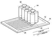
本露光装置は、本発明における描画点形成部としてDMDを用いた露光装置であって、そのDMDへ入力されるフレームデータの作成方法に特徴を有するものであるが、まず、本実施形態の露光装置の全体の構成について説明する。図1は、本実施形態の露光装置の概略構成を示す斜視図である。 The present exposure apparatus is an exposure apparatus that uses a DMD as a drawing point formation unit in the present invention, and is characterized by a method of creating frame data input to the DMD. First, the exposure according to the present embodiment is performed. The overall configuration of the apparatus will be described. FIG. 1 is a perspective view showing a schematic configuration of the exposure apparatus of the present embodiment.
本実施形態の露光装置10は、図1に示すように、感光材料12を表面に吸着して保持する平板状の移動ステージ14を備えている。そして、4本の脚部16に支持された厚い板状の設置台18の上面には、ステージ移動方向に沿って延びた2本のガイド20が設置されている。ステージ14は、その長手方向がステージ移動方向を向くように配置されると共に、ガイド20によって往復移動可能に支持されている。
As shown in FIG. 1, the
設置台18の中央部には、移動ステージ14の移動経路を跨ぐようにコの字状のゲート22が設けられている。コの字状のゲート22の端部の各々は、設置台18の両側面に固定されている。このゲート22を挟んで一方の側にはスキャナ24が設けられ、他方の側には感光材料12の先端および後端を検知する複数(たとえば2個)のセンサ26が設けられている。スキャナ24およびセンサ26はゲート22に各々取り付けられて、移動ステージ14の移動経路の上方に固定配置されている。なお、スキャナ24およびセンサ26は、これらを制御する、後述する全体制御部に接続されている。
A
スキャナ24は、図2および図3(B)に示すように、2行5列の略マトリックス状に配列された10個の露光ヘッド30を備えている。なお、以下において、m行目のn列目に配列された個々の露光ヘッドを示す場合は、露光ヘッド30mnと表記する。
As shown in FIGS. 2 and 3B, the
各露光ヘッド30は、空間光変調素子であるDMD36を備えている。DMD36は、描画素子としてのマイクロミラーが一列に配置されたマイクロミラー列が、複数平行に配列されたものであり、そのマイクロミラー列の配列方向が走査方向と所定の傾斜角度θをなすように露光ヘッド30に取り付けられている。したがって、各露光ヘッド30による露光エリア32は、図2および図3(B)に示すように、走査方向に対して傾斜した矩形状のエリアとなる。なお、以下において、m行目のn列目に配列された個々の露光ヘッドによる露光エリアを示す場合は、露光エリア32mnと表記する。
Each
DMD36の光入射側には、光ファイバの発光点が露光エリア32の長辺方向と対応する方向に沿って一列に配列されたファイバアレイ光源(図示省略)とファイバアレイ光源から出射されたレーザ光を平行光化し、その平行光化されたレーザ光の光量分布が均一になるように補正してDMD36上に集光する集光レンズ系(図示省略)とが設けられている。
On the light incident side of the
また、DMD36の光反射側には、DMD36で反射されたレーザ光を感光材料120の描画面に結像する結像レンズ系(図示省略)が配置されている。
An imaging lens system (not shown) that images the laser light reflected by the
そして、図3(A)に示すように、ステージ14の移動に伴い、感光材料12には露光ヘッド30ごとに帯状の露光済み領域34が形成されるが、その帯状の露光済み領域34のそれぞれが、隣接する露光済み領域34と部分的に重なるように、ライン状に配列された各行の露光ヘッド30の各々は、その配列方向に所定間隔ずらして配置されている。このため、1行目の露光エリア3211と露光エリア3212との間の露光できない部分は、2行目の露光エリア3221により露光することができる。
As shown in FIG. 3A, as the
DMD36は、図4に示すように、SRAMアレイ(メモリセル)56上に、マイクロミラー58が支柱により支持されて配置されたものであり、多数の(例えば、ピッチ13.68μm、1024個×768個)のマイクロミラー58が、直交する方向に2次元状に配列されて構成されたミラーデバイスである。そして、上述したようにマイクロミラー58の直下には、ヒンジ及びヨークを含む支柱を介して通常の半導体メモリの製造ラインで製造されるシリコンゲートのCMOSのSRAMアレイ56が配置されている。
As shown in FIG. 4, the
DMD36のSRAMアレイ56に制御信号としてのデジタル信号が書き込まれると、そのデジタル信号に応じた制御電圧が、マイクロミラー58毎に設けられた電極部(図示せず)に印加され、その制御電圧の印加により発生した静電気力によって支柱に支えられたマイクロミラー58が、対角線を中心として±α度(例えば±10度)の範囲で傾けられる。図5(A)は、マイクロミラー58がオン状態である+α度に傾いた状態を示し、図5(B)は、マイクロミラー58がオフ状態である−α度に傾いた状態を示す。そして、マイクロミラー58がオン状態のときにマイクロミラー58に入射された光Bは、感光材料12に向けて反射され、マイクロミラー58がオフ状態のときにマイクロミラー58に入射された光Bは、感光材料12以外の光吸収材料に向けて反射される。そして、1つのマイクロミラー58により反射された光Bが感光材料12に照射されることによって、露光対象である画像を構成する1つの描画点が感光材料12上に露光される。
When a digital signal as a control signal is written in the
また、露光装置10においては、上述したようにDMD36が、そのマイクロミラー列36aの配列方向が走査方向と所定の傾斜角度θ(ただし、0°<θ<90°)をなすように露光ヘッド30に取り付けられているので、各マイクロミラー58の露光軌跡は、図6に示すようになり、マイクロミラー58の配列ピッチよりも狭いピッチで露光することができる。
In the
そして、露光装置10には、図7に示すように、画像データ出力装置70から出力された画像データを受け付け、その受け付けた画像データに変形処理を施す画像データ変形部61と、画像データ変形部61において変形処理の施された変形処理済画像データが一時記憶される第1のフレームメモリ62と、第1のフレームメモリ62に記憶された変形処理済画像データに並替処理を施す画素データ並替部63と、画素データ並替部63により並替処理の施された並替処理済画像データが一時記憶される第2のフレームメモリ64と、第2のフレームメモリ64に記憶された並替処理済画像データに基づいてフレームデータを作成するフレームデータ作成部65と、フレームデータ作成部65から出力されたフレームデータに基づいてDMD36に制御信号を出力するDMDコントローラ65と、露光装置全体を制御する全体制御部60とを備えている。なお、画像データ変形部61、画素データ並替部63およびフレームデータ作成部65には、所定の手順を実行させるプログラムがそれぞれ格納されており、そのプログラムの手順に従って全体制御部60が装置の動作を制御する。各プログラムが実行させる所定の手順については、後で詳述する。また、全体制御部60は、ステージ14を駆動するステージ駆動装置80とファイバアレイ光源90の動作を制御するものである。
As shown in FIG. 7, the
第1のフレームメモリ62および第2のフレームメモリとしては、たとえば、DRAMを用いることができるが、その他MRAMやFRAMなども用いることができ、格納されたデータがアドレスが連続する方向に順次読み出されうるものであれば如何なるものを使用してもよい。また、格納されたデータがいわゆるバースト転送により読み出されるメモリを利用するようにしてもよい。
As the
次に、本露光装置10の作用について詳細に説明する。
Next, the operation of the
まず、コンピュータなどの画像データ出力装置70において、感光材料12に露光される画像に応じた画像データが作成され、その画像データが露光装置10に出力され、画像データ変形部61に入力される。
First, in an image
ここで、画像データ変形部61に入力される画像データDは、図8に示すように、画素データdが、主走査方向および主走査方向に直交する副走査方向に2次元状に多数配列されたものである。なお、図8における丸1〜丸24は、DMD36のマイクロミラー58を模式的に示したものであり、図8は、画像データDの各画素データdとその各画素データdが入力される各マイクロミラー58との対応関係を示している。そして、図8の各格子は、上記のように画素データを示すとともに、感光材料12上に露光される画像を構成する画素を表わしていることにもなり、画像データDは、図8に示すように、図1に示す走査方向と上記副走査方向とが一致するように作成される。また、図8における三角印は、DMD36が走査方向に1画素分だけ移動した際の、マイクロミラー58の配置を示したものである。つまり、図8における丸1〜丸24に対応する画素データdにより1つのフレームデータが作成され、図8における三角印に対応する画素データdにより上記フレームデータの次のフレームデータが作成されることになる。また、本実施形態においては、図8に示すように、画像データDの解像度は、DMD36のマイクロミラー58の解像度よりも高いものとする。
Here, as shown in FIG. 8, in the image data D input to the image
ここで、上記のようにして作成された画像データのままでフレームデータを作成したのでは、上述したようにマイクロミラー列36aの配列方向が、DMDの走査方向(画像データDの副走査方向)に対して傾きをもっているため、各マイクロミラー58に対応する画素データdをそれぞれ集めていったのでは、上述したように画像データが記憶されるメモリからの画素データの読出しに時間がかかってしまい、フレームデータの作成時間が長くなってしまう。
Here, if the frame data is generated with the image data generated as described above, the arrangement direction of the
そこで、本実施形態の露光装置10においては、画像データ変形部61において画像データに変形処理が施される。具体的には、図9に示すように、各マイクロミラー58に対応する画素データの配列方向と主走査方向とが一致するように画像データに変形処理が施される。変形処理としては、たとえば、各マイクロミラー58に対応する画素データを、図9に示す副走査方向とは逆方向にシフトする処理を行うようにすればよい。
Therefore, in the
そして、上記のようにして変形処理の施された変形処理済画像データが画像データ変形部61から出力され、第1のフレームメモリ62に格納される。なお、このとき、第1のフレームメモリ62におけるアドレスが連続する方向と、主走査方向に並ぶ画素データが格納される配列方向とが一致するように格納される。
Then, the deformed image data subjected to the deformation process as described above is output from the image
次に、上記のようにして第1のフレームメモリ62に格納された変形処理済画像データに対して、画素データ並替部63により並替処理が施される。具体的には、図9に示す変形処理済画像データにおける主走査方向に並ぶ画素データについて、所定数の画素データ毎に配置された画素データを1つずつ選択して集めることによって、同じフレームデータに属する画素データを集められ、その集められた画素データが連続して配置されるような処理が施される。上記のような処理を主走査方向に並ぶ画素データの一番左の画素データから順に施すことにより、図9に示す変形処理済画像データは、図10に示すような並替処理済画像データとされる。つまり、同じフレームデータに属する画素データが、主走査方向について連続して並んで配置されるように変形処理済画像データに対して並替処理が施される。なお、上記のような並替処理は、プログラムにより行うようにしてもよいし、ハードウェアにより行うようにしてもよい。具体的には、たとえば、図11に示すように、m個(たとえば、図9に示す変形処理済画像データに対して並替処理を施す場合には4個)の第1のレジスタ63a、m個の第1のレジスタ63aに保持された画素データから1つの画素データを選択して出力する第1のセレクタ63bおよび第1のセレクタ63bにより選択された画素データを保持する第2のレジスタ63cを備えたN個(たとえば、図9に示す変形処理済画像データに対して並替処理を施す場合には6個)の選択回路63dと、N個の選択回路63dの第2のレジスタ63cに保持された画素データのいずれか1つを選択して出力する第2のセレクタ63eと、第2のセレクタ63eから出力された画素データを保持する第3のレジスタ63fとを設けるようにしてもよい。そして、たとえば、図9に示す変形処理済画像データに並替処理を行う際には、図9に示す変形処理済画像データにおける主走査方向に並ぶ画素データを、一番左の画素データから順に、各選択回路63d毎に4つずつ出力して各選択回路63dのレジスタ63aに保持する。つまり、第1の選択回路63dには、図9の丸1に対応する画素データとその画素データから右に3つ連続して配置された画素データが保持され、第2の選択回路63dには、図9の丸2に対応する画素データとその画素データから右に3つ連続して配置された画素データが保持され、第3の選択回路63dには、図9の丸3に対応する画素データとその画素データから右に3つ連続して配置された画素データが保持され、第Nの選択回路63dには、図9の丸Nに対応する画素データとその画素データから右に3つ連続して配置された画素データが保持される。そして、各選択回路63dにおける第1のセレクタ63bにより1番目の第1のレジスタ63aに保持された画素データが選択されて出力され、それぞれ第2のレジスタ63cに保持される。そして、第2のセレクタ63eにより各選択回路63dの第2のレジスタ63cに保持された画素データが順次選択されて読み出され、第3のレジスタ63fに保持された後、順次第2のフレームメモリ64に出力され、順次格納される。そして、次に、各選択回路63dにおける第1のセレクタ63bにより2番目の第2のレジスタ63aに保持された画素データが選択されて出力され、それぞれ第2のレジスタ63cに保持される。そして、第2のセレクタ63eにより各選択回路63dの第2のレジスタ63cに保持された画素データが順次選択されて読み出され、第3のレジスタ63fに保持された後、順次第2のフレームメモリ64に出力され、順次格納される。そして、各選択回路63dの3番目と4番目の第1のレジスタ63aに保持された画素データも、上記と同様にして読み出され、第2のフレームメモリ64に格納される。そして、上記と同様の処理を、主走査方向に並んだ画素データの列毎に施すことにより、並替処理済画像データを作成することができる。
Next, the pixel
そして、図10に示すように画素データが配置された並替処理済画像データが第2のフレームメモリ64に格納される。なお、この際にも、第2のフレームメモリ64のアドレスが連続する方向と、主走査方向に並ぶ画素データが格納される配列方向とが一致するように格納される。
Then, as shown in FIG. 10, the rearranged image data in which the pixel data is arranged is stored in the
そして、次に、上記のようにして第2のフレームメモリ64に格納された並替処理済画像データに基づいて、フレームデータ作成部65がフレームデータを作成する。具体的には、フレームデータ作成部65は、図10に示す並替処理済画像データにおける同じフレームデータに属する画素データ、たとえば、丸1〜丸24のマイクロミラー58に対応する画素データを選択して集めることによって図12に示すようなフレームデータ1を作成する。そして、次に、図10における三角印に対応する画素データを選択して集めることによって図12に示すフレームデータ2を作成する。そして、上記と同様の処理を繰り返して行うことによって画像データDに基づいて全てのフレームデータを作成する。
Next, the frame
そして、フレームデータ作成部65は、上記のようにして作成した各フレームデータを順次DMDコントローラ66に出力し、DMDコントローラ66は入力されたフレームデータに応じた制御信号を生成する。なお、上記のようなフレームデータは各露光ヘッド30のDMD36毎に作成され、DMD36毎に制御信号が生成される。
Then, the frame
そして、上記のようにして各露光ヘッド30毎の制御信号が生成されるとともに、全体制御部60からステージ駆動装置80にステージ駆動制御信号が出力され、ステージ駆動装置80はステージ駆動制御信号に応じて移動ステージ14をガイド20に沿ってステージ移動方向へ所望の速度で移動させる。そして、移動ステージ14がゲート22下を通過する際、ゲート22に取り付けられたセンサ26により感光材料12の先端が検出されると、DMDコントローラ65から各露光ヘッド30のDMD36に制御信号が出力され、各露光ヘッド30毎の描画が開始される。
Then, a control signal for each
そして、感光材料12が移動ステージ14とともに一定速度で移動し、感光材料12がスキャナ24によりステージ移動方向と反対の方向に走査され、露光ヘッド30毎に帯状の露光済み領域34が形成される。
Then, the
上記のようにして、スキャナ24による感光材料12の走査が終了し、センサ26で感光材料12の後端が検出されると、移動ステージ14は、ステージ駆動装置72により、ガイド20に沿ってゲート22の最上流側にある原点に復帰し、新たな感光材料12が設置された後、再度、ガイド20に沿ってゲート22の上流側から下流側に一定速度で移動する。
As described above, when the scanning of the
なお、上記説明においては、画像データDの解像度と感光材料14上に露光される画像の解像度とが同じ場合について説明したが、画像データDの解像度が露光される画像の解像度よりも低くてもよい。つまり、画像データDの1つの画素データdを用いて複数のマイクロミラー58により露光点を形成し、この複数の露光点により1つの画素を構成するようにしてもよい。たとえば、画像データDの1つの画素データを用いて4のマイクロミラー58により露光点を形成し、この複数の露光点により1つの画素を構成する場合における、画素データdとマイクロミラー58と画素との対応関係を図13に示す。図13における斜線部分が画像データDにおける1つの画素データdに対応する部分であり、この範囲を4つのマイクロミラー58により露光される露光点により露光する。上記のような露光を行う場合におけるフレームデータを作成する際には、まず、上記と同様に、画像データDに変形処理を施し、図14に示すような変形処理済画像データを生成し、その後、上記と同様に、変形処理済画像データに並替処理を施し、その並替処理済画像データを第2のフレームメモリ64に上記と同様に格納した後、その第2のフレームメモリ64に格納された各画素データを複数回読み出すことにより、フレームデータを作成するようにすればよい。具体的には、たとえば、上記のように4つのマイクロミラー58により1つの画素を露光するようにする場合には、たとえば、図9に示す丸1から丸6に対応する画素データ、丸7から丸12に対応する画素データ、丸13から丸18に対応する画素データ、丸19から丸24に対応する画素データをそれぞれ4回ずつ読み出して、図15に示すようなフレームデータを作成するようにすればよい。なお、ここでは、図8に示す丸1から丸24の各丸が、それぞれ図13に示す斜線部分の4つのマイクロミラーを表わすものとする。また、並替処理前の変形処理済画像データにおける画素データを複数回読み出すことによりフレームデータを作成するようにしてもよい。
In the above description, the case where the resolution of the image data D is the same as the resolution of the image exposed on the
また、たとえば、図16に示すようなN×M個のマイクロミラー58からなるDMD36を、走査方向に対して、図16に示すような傾斜角θだけ傾け、同じ走査線Lを複数のマイクロミラー58により走査する、いわゆる多重露光を行う場合には、N×aのマイクロミラー58からなるエリア1〜4によって同じ画像を露光することになるが、各エリアのマイクロミラー列に入力される描画点データは、各エリア毎に、その露光順にマイクロミラー列が延びる方向に1画素ずつずれることになる。
Further, for example, a
したがって、上記のような露光の際に用いられるフレームデータを作成する際には、まず、エリア1のマイクロミラー58に対応する画像データに対し、上記と同様に変形処理および並替処理を施して図17に示すような、エリア1に対応する並替処理済画像データを作成し、次に、エリア1のマイクロミラー58に対応する画像データについて変形処理を施した後、1画素データだけ右にシフトした画素データ、つまり右から2番目の画素データから、上記と同様に並替処理を行うことにより、図17に示すようなエリア2に対応する並替処理済画像データを作成し、次に、エリア1に対応する変形処理済画像データについて、さらに1画素データだけ右にシフトした画素データ、つまり右から3番目の画素データから、上記と同様に並替処理を行うことにより、図17に示すようなエリア3に対応する並替処理済画像データを作成し、そして、エリア1に対応する変形処理済画像データについて、さらに1画素データだけ右にシフトした画素データ、つまり右から4番目の画素データから、上記と同様に並替処理を行うことにより、図17に示すようなエリア4に対応する並替処理済画像データを作成する。なお、エリア2からエリア4において右にシフトした分、図17に示すように0のデータを挿入する。
Therefore, when creating the frame data used for the exposure as described above, first, the image data corresponding to the
そして、上記のようにしてエリア1からエリア4までの並替処理済データを作成した後、各エリア毎に、各ブロックからそれぞれ同じフレームデータに属する画素データが選択されて集められ、各エリア毎の部分フレームデータが作成され、DMD36全体のフレームデータが作成される。
Then, after creating rearranged data from
なお、上記のようにエリア1からエリア4までの並替処理済データを作成する際、たとえば、エリア1の並替処理済データだけをメモリなどに記憶しておき、残りのエリア2からエリア4まで並替処理済データについては、上記メモリに記憶されたエリア1の並替処理済データを利用して作成するようにすればメモリの容量を減らすことができ、コストの削減およびメモリからの読出速度の高速化を図ることができる。
When creating the rearranged data from
また、上記のような多重露光においても、たとえば、画像データの主走査方向の解像度が露光される画像の解像度よりも低く、複数のマイクロミラー58により露光点を形成するような場合には、各エリアにおいて、各ブロックのN個の画素データを複数回読み出すことによって、上記複数のマイクロミラー58に対応する描画点データを生成し、その描画点データを用いて部分フレームデータを作成するようにしてもよい。
Also in the multiple exposure as described above, for example, when the resolution of the image data in the main scanning direction is lower than the resolution of the image to be exposed and the exposure points are formed by a plurality of
また、上記実施形態では、空間光変調素子としてDMDを備えた露光装置について説明したが、このような反射型空間光変調素子の他に、透過型空間光変調素子を使用することもできる。 In the above-described embodiment, the exposure apparatus including the DMD as the spatial light modulation element has been described. However, in addition to the reflective spatial light modulation element, a transmissive spatial light modulation element can also be used.
また、上記実施形態では、いわゆるフラッドベッドタイプの露光装置を例に挙げたが、感光材料が巻きつけられるドラムを有する、いわゆるアウタードラムタイプの露光装置としてもよい。 In the above embodiment, a so-called flood bed type exposure apparatus has been described as an example. However, a so-called outer drum type exposure apparatus having a drum around which a photosensitive material is wound may be used.
また、上記実施形態の露光対象である感光材料12は、プリント基板や、ディスプレイ用のフィルタであってもよい。また、感光材料12の形状は、シート状のものであっても、長尺状のもの(フレキシブル基板など)であってもよい。
Further, the
また、本発明における描画方法および装置は、インクジェット方式などのプリンタにおける描画制御にも適用することができる。たとえば、インクの吐出による描画点を、本発明と同様の方法で制御することができる。つまり、本発明における描画素子を、インクの吐出などによって描画点を打つ素子に置き換えて考慮することができる。 The drawing method and apparatus according to the present invention can also be applied to drawing control in an ink jet printer or the like. For example, the drawing point by ink ejection can be controlled by the same method as in the present invention. In other words, the drawing element in the present invention can be considered by replacing it with an element that strikes a drawing point by ink ejection or the like.
1 画像データ
5 画素データ
10 露光装置
12 感光材料
14 移動ステージ
24 スキャナ
30 露光ヘッド
36 DMD
56 SRAMアレイ
58 マイクロミラー
63a 第1のレジスタ
63b 第1のセレクタ
63c 第2のレジスタ
63d 選択回路
63e 第2のセレクタ
63f 第3のレジスタ
DESCRIPTION OF
56
Claims (20)
前記画像データにおける前記描画素子群に対応する画素データが前記主走査方向に並ぶように前記画像データに変形処理を施し、
該変形処理済画像データに基づいて前記複数の描画点データを取得して前記フレームデータを作成することを特徴とするフレームデータ作成方法。 A drawing point forming unit in which a plurality of drawing elements forming a drawing point on a drawing surface are arranged in a line is arranged in parallel with respect to the drawing surface. A plurality of elements corresponding to the drawing elements are moved relative to each other in the scanning direction that makes a predetermined inclination angle θ (where 0 ° <θ <90 °) with the arrangement direction of the element group. The frame data composed of the drawing point data is sequentially input to the drawing point forming unit, and the drawing point group is sequentially formed in time series so that an image in which the plurality of drawing points are arranged in a two-dimensional manner is formed on the drawing surface. A frame data creation method for creating the frame data used in forming the pixel data, the pixel corresponding to the drawing point data in a sub-scanning direction corresponding to the scanning direction and a main scanning direction orthogonal to the sub-scanning direction Data is 2 Arranged based on shape, based on the image data corresponding to the image, the frame data generation method of generating the frame data by obtaining the plurality of drawing point data,
The image data is subjected to deformation processing so that pixel data corresponding to the drawing element group in the image data is aligned in the main scanning direction,
A frame data creation method characterized in that the frame data is created by acquiring the plurality of drawing point data based on the transformed image data.
該格納された画素データを前記記憶手段から読み出して前記複数の描画点データを取得することを特徴とする請求項1記載のフレームデータ作成方法。 The pixel data is stored in the storage means for storing the transformed image data so that the direction in which the addresses of the storage means are continuous and the arrangement direction in which the pixel data corresponding to the drawing element group are stored And
2. The frame data creation method according to claim 1, wherein the stored pixel data is read from the storage means to obtain the plurality of drawing point data.
該並び替え後の変形処理済画像データに基づいて前記フレームデータを作成することを特徴とする請求項1から3いずれか1項記載のフレームデータ作成方法。 Rearranging the pixel data in the scanning direction so that pixel data belonging to the same frame data corresponding to each drawing element of the drawing element group is continuously arranged in the main scanning direction;
4. The frame data creation method according to claim 1, wherein the frame data is created based on the transformed image data after the rearrangement.
前記並び替え後の変形処理済画像データの各画素データを複数回用いて前記描画素子に対応する前記描画点データを生成し、
該生成された描画点データを用いて前記フレームデータを作成することを特徴とする請求項4記載のフレームデータ作成方法。 In the case where the resolution of the image data is lower than the resolution of the image drawn on the drawing surface,
Using the pixel data of the transformed image data after the rearrangement a plurality of times to generate the drawing point data corresponding to the drawing element;
5. The frame data creation method according to claim 4, wherein the frame data is created using the generated drawing point data.
前記各分割領域に対応する並び替え後の変形処理済画像データを、前記多重描画の順に応じてそれぞれ前記主走査方向にシフトし、
該シフトされた並び替え後の変形処理済画像データに基づいて前記フレームデータを作成することを特徴とする請求項4項記載のフレームデータ作成方法。 In the case where the drawing point forming unit is divided into a plurality of divided regions in the arrangement direction and multiple drawing is performed by the plurality of divided regions,
The transformed image data after rearrangement corresponding to each of the divided areas is shifted in the main scanning direction according to the order of the multiple drawing,
5. The frame data creation method according to claim 4, wherein the frame data is created based on the shifted rearranged image data after rearrangement.
前記描画点形成部を前記描画面に対して前記走査方向に相対的に移動させるとともに、該走査方向への移動に応じて前記描画点形成部に順次前記各フレームデータを入力して前記描画点群を時系列に形成し、前記描画面上に前記画像を形成することを特徴とする描画方法。 Each frame data is acquired using the frame data creation method according to any one of claims 1 to 6,
The drawing point forming unit is moved relative to the drawing surface in the scanning direction, and each frame data is sequentially input to the drawing point forming unit in accordance with the movement in the scanning direction. A drawing method comprising forming a group in time series and forming the image on the drawing surface.
前記画像データにおける前記描画素子群に対応する画素データが前記主走査方向に並ぶように前記画像データに変形処理を施す画像データ変形部と、
該画像データ変形部により変形処理の施された変形処理済画像データに基づいて前記複数の描画点データを取得して前記フレームデータを作成するフレームデータ作成部とを備えたことを特徴とするフレーム作成装置。 A drawing point forming unit in which a plurality of drawing elements forming a drawing point on a drawing surface are arranged in a line is arranged in parallel with respect to the drawing surface. A plurality of elements corresponding to the drawing elements are moved relative to each other in the scanning direction that makes a predetermined inclination angle θ (where 0 ° <θ <90 °) with the arrangement direction of the element group. By sequentially inputting frame data composed of the drawing point data to the drawing point forming unit and forming the drawing point group in time series, an image in which a plurality of the drawing points are arranged in a two-dimensional manner is formed on the drawing surface. A frame data creation device for creating the frame data used in forming the pixel data, the pixel corresponding to the drawing point data in a sub-scanning direction corresponding to the scanning direction and a main scanning direction orthogonal to the sub-scanning direction Data is 2 Arranged based on shape, based on the image data corresponding to said image, the frame data generating apparatus for generating the frame data by obtaining the plurality of drawing point data,
An image data deformation unit that performs a deformation process on the image data so that pixel data corresponding to the drawing element group in the image data is aligned in the main scanning direction;
A frame data generating unit that acquires the plurality of drawing point data based on the deformed image data that has been subjected to the deforming process by the image data deforming unit and generates the frame data; Creation device.
該記憶手段のアドレスが連続する方向と前記描画素子群に対応する画素データが格納される配列方向とが一致するように前記画素データを格納する記憶制御手段とをさらに備え、
前記フレームデータ作成部が、前記記憶手段に格納された画素データを前記記憶手段から読み出して前記複数の描画点データを取得するものであることを特徴とする請求項8記載のフレームデータ作成装置。 Storage means for storing the transformed image data;
Storage control means for storing the pixel data so that a direction in which the addresses of the storage means are continuous and an arrangement direction in which the pixel data corresponding to the drawing element group is stored are the same;
9. The frame data creation apparatus according to claim 8, wherein the frame data creation unit reads the pixel data stored in the storage unit from the storage unit and acquires the plurality of drawing point data.
前記フレームデータ作成部が、前記画素データ並替部によって並び替えられた後の変形処理済画像データに基づいて前記フレームデータを作成するものであることを特徴とする請求項8から10いずれか1項記載のフレームデータ作成装置。 A pixel data rearrangement unit that rearranges the pixel data in the scanning direction so that pixel data belonging to the same frame data corresponding to the drawing elements in the drawing element group is continuously arranged in the main scanning direction; In addition,
The frame data creation unit creates the frame data based on the transformed image data after being rearranged by the pixel data rearrangement unit. The frame data creation device described in the item.
前記フレームデータ作成部が、前記並び変えられた後の変形処理済画像データの各画素データを複数回用いて前記描画素子に対応する前記描画点データを生成し、該生成された描画点データを用いて前記フレームデータを作成するものであることを特徴とする請求項11記載のフレームデータ作成装置。 In the case where the resolution of the image data is lower than the resolution of the image drawn on the drawing surface,
The frame data generation unit generates the drawing point data corresponding to the drawing element by using each pixel data of the transformed image data after the rearrangement a plurality of times, and generates the generated drawing point data. 12. The frame data creating apparatus according to claim 11, wherein the frame data is created by using the frame data.
前記フレームデータ作成部が、前記各分割領域に対応する変形処理済画像データを、前記多重描画の順に応じてそれぞれ前記主走査方向にシフトし、該シフトされた変形処理済画像データに基づいて前記フレームデータを作成するものであることを特徴とする請求項11記載のフレームデータ作成装置。 In the case where the drawing point forming unit is divided into a plurality of divided regions in the arrangement direction and multiple drawing is performed by the plurality of divided regions,
The frame data creation unit shifts the deformed image data corresponding to each of the divided areas in the main scanning direction according to the order of the multiple drawing, and based on the shifted deformed image data 12. The frame data creating apparatus according to claim 11, wherein the frame data creating apparatus is for creating frame data.
入力された前記フレームデータに基づいて複数の描画点からなる描画点郡を描画面上に形成する描画点形成部と、
該描画点形成部を前記描画面に対して前記走査方向に相対的に移動させる移動手段と、
該移動手段による走査方向への移動に応じて前記フレームデータ作成装置において作成されたフレームデータを前記描画点形成部に順次入力し、前記描画点形成部に前記描画点群を時系列に順次形成させて複数の前記描画点が2次元状に配置された画像を前記描画面上に形成させる画像形成制御部とを備えたことを特徴とする描画装置。 A frame data creation device according to claim 8;
A drawing point forming unit for forming a drawing point group consisting of a plurality of drawing points on the drawing surface based on the input frame data;
Moving means for moving the drawing point forming portion relative to the drawing surface in the scanning direction;
The frame data created in the frame data creation device is sequentially input to the drawing point forming unit according to the movement in the scanning direction by the moving means, and the drawing point group is sequentially formed in the drawing point forming unit in time series. An image forming control unit configured to form an image in which a plurality of the drawing points are arranged two-dimensionally on the drawing surface.
前記画像データにおける前記描画素子群に対応する画素データが前記主走査方向に並ぶように前記画像データに変形処理を施す手順と、
該変形処理済画像データに基づいて前記複数の描画点データを取得して前記フレームデータを作成する手順とをコンピュータに実行させることを特徴とするフレームデータ作成プログラム。 A drawing point forming unit in which a plurality of drawing elements forming a drawing point on a drawing surface are arranged in a line is arranged in parallel with respect to the drawing surface. A plurality of elements corresponding to the drawing elements are moved relative to each other in the scanning direction that makes a predetermined inclination angle θ (where 0 ° <θ <90 °) with the arrangement direction of the element group. The frame data composed of the drawing point data is sequentially input to the drawing point forming unit, and the drawing point group is sequentially formed in time series so that an image in which the plurality of drawing points are arranged in a two-dimensional manner is formed on the drawing surface. A frame data creation program for causing a computer to execute a procedure for creating the frame data used in forming the frame data in a sub-scanning direction corresponding to the scanning direction and a main scanning direction orthogonal to the sub-scanning direction. Based on image data corresponding to the image in which pixel data corresponding to the image point data is two-dimensionally arranged, the computer is caused to execute a procedure for obtaining the plurality of drawing point data and creating the frame data. In the frame data creation program,
A procedure for performing a transformation process on the image data so that pixel data corresponding to the drawing element group in the image data are arranged in the main scanning direction;
A frame data creation program for causing a computer to execute a procedure for obtaining the plurality of drawing point data based on the transformed image data and creating the frame data.
前記格納された画素データを前記記憶手段から読み出して前記複数の描画点データを取得する手順をコンピュータに実行させることを特徴とする請求項15記載のフレームデータ作成プログラム。 In the storage means for storing the transformed image data, the pixel data is stored so that the direction in which the addresses of the storage means are continuous and the arrangement direction in which the pixel data corresponding to the drawing element group is stored coincide with each other. Let the computer perform further steps,
16. The frame data creation program according to claim 15, further comprising causing a computer to execute a procedure of reading the stored pixel data from the storage unit and acquiring the plurality of drawing point data.
該並び替え後の変形処理済画像データに基づいて前記フレームデータを作成する手順をコンピュータに実行させることを特徴とする請求項15から17いずれか1項記載のフレームデータ作成プログラム。 The computer further executes a procedure for rearranging the pixel data in the scanning direction so that the pixel data belonging to the same frame data corresponding to the drawing elements in the drawing element group is continuously arranged in the main scanning direction. Let
18. The frame data creation program according to claim 15, which causes a computer to execute a procedure for creating the frame data based on the transformed image data after the rearrangement.
前記並び替え後の変形処理済画像データの各画素データを複数回用いて前記描画素子に対応する前記描画点データを生成する手順をさらにコンピュータに実行させ、
前記生成された描画点データを用いて前記フレームデータを作成する手順をコンピュータに実行させることを特徴とする請求項18記載のフレームデータ作成プログラム。 In the case where the resolution of the image data is lower than the resolution of the image drawn on the drawing surface,
Further causing the computer to execute a procedure of generating the drawing point data corresponding to the drawing element by using each pixel data of the transformed image data after the rearrangement a plurality of times,
19. The program for creating frame data according to claim 18, which causes a computer to execute a procedure for creating the frame data using the generated drawing point data.
前記各分割領域に対応する並び替え後の変形処理済画像データを、前記多重描画の順に応じてそれぞれ前記主走査方向にシフトする手順をさらにコンピュータに実行させ、
前記シフトされた並び替え後の変形処理済画像データに基づいて前記フレームデータを作成する手順をコンピュータに実行させることを特徴とする請求項18項記載のフレームデータ作成プログラム。 In the case where the drawing point forming unit is divided into a plurality of divided regions in the arrangement direction and multiple drawing is performed by the plurality of divided regions,
The computer further executes a procedure for shifting the transformed image data after rearrangement corresponding to each of the divided areas in the main scanning direction according to the order of the multiple drawing,
19. The frame data creation program according to claim 18, which causes a computer to execute a procedure for creating the frame data based on the shifted rearranged image data after rearrangement.
Priority Applications (6)
| Application Number | Priority Date | Filing Date | Title |
|---|---|---|---|
| JP2005004004A JP2006192607A (en) | 2005-01-11 | 2005-01-11 | Method and device for preparing frame data, frame data-preparation program, and method and device for drawing |
| PCT/JP2006/300318 WO2006075673A1 (en) | 2005-01-11 | 2006-01-06 | Frame data creation method and device, frame data creation program, and plotting method and device |
| CNA2006800019586A CN101102900A (en) | 2005-01-11 | 2006-01-06 | Frame data generation method and device, frame data generation program, rendering method and device |
| US11/813,704 US20090066812A1 (en) | 2005-01-11 | 2006-01-06 | Frame data creation method and apparatus, frame data creation program, and plotting method and apparatus |
| KR1020077017265A KR20070104363A (en) | 2005-01-11 | 2006-01-06 | Frame data creation method and apparatus, frame data creation program, and drawing method and apparatus |
| TW095100712A TW200637350A (en) | 2005-01-11 | 2006-01-09 | Frame data making method and frame data making device and frame data making program, plotting method and plotting device |
Applications Claiming Priority (1)
| Application Number | Priority Date | Filing Date | Title |
|---|---|---|---|
| JP2005004004A JP2006192607A (en) | 2005-01-11 | 2005-01-11 | Method and device for preparing frame data, frame data-preparation program, and method and device for drawing |
Publications (1)
| Publication Number | Publication Date |
|---|---|
| JP2006192607A true JP2006192607A (en) | 2006-07-27 |
Family
ID=36677697
Family Applications (1)
| Application Number | Title | Priority Date | Filing Date |
|---|---|---|---|
| JP2005004004A Pending JP2006192607A (en) | 2005-01-11 | 2005-01-11 | Method and device for preparing frame data, frame data-preparation program, and method and device for drawing |
Country Status (6)
| Country | Link |
|---|---|
| US (1) | US20090066812A1 (en) |
| JP (1) | JP2006192607A (en) |
| KR (1) | KR20070104363A (en) |
| CN (1) | CN101102900A (en) |
| TW (1) | TW200637350A (en) |
| WO (1) | WO2006075673A1 (en) |
Cited By (1)
| Publication number | Priority date | Publication date | Assignee | Title |
|---|---|---|---|---|
| WO2007037236A1 (en) * | 2005-09-29 | 2007-04-05 | Fujifilm Corporation | Frame data producing apparatus, method and plotting apparatus |
Families Citing this family (6)
| Publication number | Priority date | Publication date | Assignee | Title |
|---|---|---|---|---|
| JP4937705B2 (en) * | 2006-11-14 | 2012-05-23 | 株式会社オーク製作所 | Multiple exposure equipment |
| TWI386911B (en) * | 2007-10-24 | 2013-02-21 | Novatek Microelectronics Corp | Apparatus and method for sorting raw data with horizontal division |
| JP2013257665A (en) * | 2012-06-11 | 2013-12-26 | Canon Inc | Movie processing apparatus and control method therefor |
| CN102778819B (en) * | 2012-07-31 | 2014-10-15 | 中国科学院长春光学精密机械与物理研究所 | Exposure frame data generation method used for dot-matrix maskless photoetching |
| CN102890427B (en) * | 2012-09-18 | 2014-10-01 | 天津津芯微电子科技有限公司 | A Method of Oblique Data Preparation in FPGA of Direct Write Lithography System |
| US20160180821A1 (en) * | 2014-12-23 | 2016-06-23 | Intel Corporation | Distributed memory panel |
Family Cites Families (5)
| Publication number | Priority date | Publication date | Assignee | Title |
|---|---|---|---|---|
| JP2984432B2 (en) * | 1991-10-11 | 1999-11-29 | キヤノン株式会社 | Printer control device |
| DE69221410T2 (en) * | 1991-09-19 | 1997-12-11 | Canon Kk | Serial recording process with the possibility to change the resolution |
| JP4704635B2 (en) * | 2001-09-28 | 2011-06-15 | 株式会社セイコーアイ・インフォテック | Inkjet printer |
| JP2004009595A (en) * | 2002-06-07 | 2004-01-15 | Fuji Photo Film Co Ltd | Exposure head and exposure device |
| JP2004330536A (en) * | 2003-05-06 | 2004-11-25 | Fuji Photo Film Co Ltd | Exposure head |
-
2005
- 2005-01-11 JP JP2005004004A patent/JP2006192607A/en active Pending
-
2006
- 2006-01-06 WO PCT/JP2006/300318 patent/WO2006075673A1/en not_active Ceased
- 2006-01-06 US US11/813,704 patent/US20090066812A1/en not_active Abandoned
- 2006-01-06 CN CNA2006800019586A patent/CN101102900A/en active Pending
- 2006-01-06 KR KR1020077017265A patent/KR20070104363A/en not_active Withdrawn
- 2006-01-09 TW TW095100712A patent/TW200637350A/en unknown
Cited By (1)
| Publication number | Priority date | Publication date | Assignee | Title |
|---|---|---|---|---|
| WO2007037236A1 (en) * | 2005-09-29 | 2007-04-05 | Fujifilm Corporation | Frame data producing apparatus, method and plotting apparatus |
Also Published As
| Publication number | Publication date |
|---|---|
| WO2006075673A1 (en) | 2006-07-20 |
| TW200637350A (en) | 2006-10-16 |
| US20090066812A1 (en) | 2009-03-12 |
| CN101102900A (en) | 2008-01-09 |
| WO2006075673A8 (en) | 2007-09-27 |
| KR20070104363A (en) | 2007-10-25 |
Similar Documents
| Publication | Publication Date | Title |
|---|---|---|
| JP5697188B2 (en) | Exposure apparatus and exposure method | |
| CN101154056A (en) | Drawing point data acquisition method and device, drawing method and device | |
| JP4390189B2 (en) | Pattern drawing device | |
| JP2006192607A (en) | Method and device for preparing frame data, frame data-preparation program, and method and device for drawing | |
| JP2010134375A (en) | Drawing apparatus and drawing method | |
| US20100123745A1 (en) | Frame data creation device, creation method, creation program, storage medium storing the program, and imaging device | |
| US20090059295A1 (en) | Plotting Device and Image Data Creation Method | |
| JP4647355B2 (en) | Multi-beam exposure method and apparatus | |
| JP4209344B2 (en) | Exposure head, image exposure apparatus, and image exposure method | |
| US20070291348A1 (en) | Tracing Method and Apparatus | |
| KR101343906B1 (en) | Writing device and drawing method | |
| JP4895571B2 (en) | Drawing apparatus and image length correction method | |
| JP4919378B2 (en) | Drawing point data acquisition method and apparatus, and drawing method and apparatus | |
| JP2006327084A (en) | Frame data origination method, apparatus, and program | |
| JP4532381B2 (en) | Drawing method and apparatus | |
| JP2006113412A (en) | Drawing method and drawing apparatus | |
| WO2007037165A1 (en) | Drawing data acquiring method and device, and drawing method and apparatus | |
| WO2006106746A1 (en) | Plotting point data acquisition method and device, plotting method and device | |
| JP2006272854A (en) | Method and device for forming frame data, and writing method and device | |
| WO2006090737A1 (en) | Image data storing method, controller, and program, frame data creating method, device, and program, data acquiring method and device, and drawing method and device | |
| JP2006285575A (en) | Image processing method, program, and image processing system | |
| JP2006085070A (en) | Multi-beam exposure method and device | |
| JP2006337614A (en) | Drawing method and apparatus | |
| JP2007013035A (en) | Drawing apparatus, drawing method, and program for drawing | |
| JP2008065094A (en) | Drawing processing circuit and drawing method |
Legal Events
| Date | Code | Title | Description |
|---|---|---|---|
| A711 | Notification of change in applicant |
Free format text: JAPANESE INTERMEDIATE CODE: A712 Effective date: 20061208 |
|
| A621 | Written request for application examination |
Free format text: JAPANESE INTERMEDIATE CODE: A621 Effective date: 20070713 |
|
| A131 | Notification of reasons for refusal |
Free format text: JAPANESE INTERMEDIATE CODE: A131 Effective date: 20080401 |
|
| A02 | Decision of refusal |
Free format text: JAPANESE INTERMEDIATE CODE: A02 Effective date: 20080722 |