JP2006048366A - Non-contact IC tag sheet manufacturing method, non-contact IC tag sheet manufacturing apparatus, interposer mounting method, and interposer mounting apparatus - Google Patents
Non-contact IC tag sheet manufacturing method, non-contact IC tag sheet manufacturing apparatus, interposer mounting method, and interposer mounting apparatus Download PDFInfo
- Publication number
- JP2006048366A JP2006048366A JP2004228375A JP2004228375A JP2006048366A JP 2006048366 A JP2006048366 A JP 2006048366A JP 2004228375 A JP2004228375 A JP 2004228375A JP 2004228375 A JP2004228375 A JP 2004228375A JP 2006048366 A JP2006048366 A JP 2006048366A
- Authority
- JP
- Japan
- Prior art keywords
- sheet
- interposer
- contact
- tag
- speed
- Prior art date
- Legal status (The legal status is an assumption and is not a legal conclusion. Google has not performed a legal analysis and makes no representation as to the accuracy of the status listed.)
- Withdrawn
Links
Images






Landscapes
- Details Of Aerials (AREA)
Abstract
【課題】 非接触ICタグ付シートを単純かつ容易に製造することができる製造方法を提供する。
【解決手段】 製造方法は、ICチップ実装済シート10を供給する工程と、搬送されるICチップ実装済シートからインターポーザー2を順次形成する工程と、形成されたインターポーザーを、一定の回転速度で回転する搬送部材41の保持部42に保持させて搬送する工程と、被搭載体20を供給する工程と、搬送される被搭載体上にインターポーザーを順次実装する工程とを備えている。ICチップ実装済シートは低速の第1速度で搬送される。被搭載体は高速の第2速度で搬送される。インターポーザーを受け取る際に保持部は第1速度で移動し、インターポーザーを実装する際に保持部は第2速度で移動する
【選択図】 図1PROBLEM TO BE SOLVED: To provide a manufacturing method capable of simply and easily manufacturing a sheet with a non-contact IC tag.
A manufacturing method includes a step of supplying an IC chip mounted sheet 10, a step of sequentially forming an interposer 2 from a conveyed IC chip mounted sheet, and the formed interposer at a constant rotational speed. And holding the holding member 42 of the carrying member 41 rotating in step, carrying the carrying body 20, and sequentially mounting the interposer on the carrying body to be carried. The IC chip mounted sheet is conveyed at a low first speed. The mounted body is transported at a high-speed second speed. The holding unit moves at the first speed when receiving the interposer, and the holding unit moves at the second speed when mounting the interposer.
Description
本発明は、外部のリーダ・ライタと非接触でデータの授受を行うことができる非接触ICタグを有する非接触ICタグ付シートを製造する製造方法および製造装置に関する。また、本発明は、非接触ICタグ付シートを製造する際におけるインターポーザーの実装方法および実装装置に関する。 The present invention relates to a manufacturing method and a manufacturing apparatus for manufacturing a sheet with a non-contact IC tag having a non-contact IC tag that can exchange data with an external reader / writer in a non-contact manner. The present invention also relates to an interposer mounting method and mounting device for manufacturing a sheet with a non-contact IC tag.
外部のリーダ・ライタと非接触でデータの授受を行う非接触ICタグとして、基材シート上に形成され一対の接点を有するアンテナと、インターポーザーとを備えるものが知られている。 2. Description of the Related Art As a non-contact IC tag that exchanges data without contact with an external reader / writer, an RFID tag that includes an antenna formed on a base sheet and having a pair of contacts and an interposer is known.
このうち、インターポーザーは一対の拡大電極と、各々が異なる拡大電極に接合された一対の電極を有するICチップとを有しており、インターポーザーの各拡大電極はアンテナの異なる接点に電気的に接続されている。また、アンテナの形状は、ICタグとリーダ・ライタとの間でデータの送受信を行う際の電磁波の周波数によって決定される。 Of these, the interposer has a pair of enlarged electrodes and an IC chip having a pair of electrodes joined to different enlarged electrodes, and each enlarged electrode of the interposer is electrically connected to a different contact of the antenna. It is connected. The shape of the antenna is determined by the frequency of electromagnetic waves when data is transmitted and received between the IC tag and the reader / writer.
このようなインターポーザーの製造方法としては、非導電体シート上に送り方向に延びる一対の導電体を設け、次に一対の導電体間にICチップを連続して実装することによって、まずインターポーザー付シート(ICチップ実装済シートともいう)を作製する。そして、このインターポーザー付シートをICチップ毎に断裁することによって、個々のインターポーザーを得ることができる。 As a method for manufacturing such an interposer, a pair of conductors extending in the feeding direction is provided on a non-conductor sheet, and then an IC chip is continuously mounted between the pair of conductors. An attached sheet (also referred to as an IC chip mounted sheet) is produced. And by cutting this sheet with an interposer for each IC chip, individual interposers can be obtained.
一方、アンテナも、帯状に延びる基材シート上に、印刷、箔の転写、エッチング等によって複数のアンテナを形成することによってアンテナ形成済シートとして連続的に作製され、このアンテナ形成済シートをアンテナ毎に断裁することによって個々のアンテナが得られる。 On the other hand, the antenna is also continuously formed as an antenna-formed sheet by forming a plurality of antennas on a base material sheet extending in a strip shape by printing, foil transfer, etching, etc. Individual antennas can be obtained by cutting the antenna.
この場合、インターポーザーとアンテナとを接合することにより作製される非接触ICタグは、インターポーザー付シートをICチップ毎に断裁してインターポーザーを形成し、シート状のアンテナ形成済シートにインターポーザーを順次実装することによって、帯状に延びるシート上に多数の非接触ICタグが形成された非接触ICタグ付シートを連続的に作製し、この非接触ICタグ付シートをICタグ毎に断裁することにより得ることが生産効率的に望ましい。 In this case, the non-contact IC tag produced by joining the interposer and the antenna cuts the sheet with the interposer for each IC chip to form the interposer, and the interposer is formed on the sheet-like antenna-formed sheet. By successively mounting, a sheet with a non-contact IC tag in which a large number of non-contact IC tags are formed on a sheet extending in a strip shape is continuously manufactured, and the sheet with the non-contact IC tag is cut for each IC tag. It is desirable in terms of production efficiency to obtain the above.
このため、このような非接触ICタグ付シートの製造方法の開発が行われている(例えば特許文献1参照)。 For this reason, development of the manufacturing method of such a sheet | seat with a non-contact IC tag is performed (for example, refer patent document 1).
なお、リーダ・ライタとデータを送受信する際に用いられる電磁波の周波数帯によっては、インターポーザー自体を非接触ICタグとして用いることができる。この場合、一対の拡大電極がアンテナとして機能するが、最終的な製品または製品を包装する包装体への実装を容易にするため、一対の拡大電極をアンテナ形成済シートのアンテナに接合することもある。 Note that the interposer itself can be used as a non-contact IC tag depending on the frequency band of the electromagnetic wave used when transmitting / receiving data to / from the reader / writer. In this case, the pair of enlarged electrodes function as an antenna, but the pair of enlarged electrodes may be joined to the antenna of the antenna-formed sheet in order to facilitate mounting on the final product or a packaging body for packaging the product. is there.
また、非接触ICタグとして機能するインターポーザーが製品や製品を包装する包装体等に直接実装されることもある。この場合も同様に、シート状の被搭載体、例えば、断裁されてカードを構成するプラスチックシートや断裁されて包装袋を構成するビニルシート等に、インターポーザー付シートをICチップ毎に断裁して形成したインターポーザーを順次実装することが生産効率的に好ましい。 In addition, an interposer that functions as a non-contact IC tag may be directly mounted on a product or a package that wraps the product. Similarly, in this case, a sheet with an interposer is cut for each IC chip on a sheet-like mounted body, for example, a plastic sheet cut to form a card or a vinyl sheet cut to form a packaging bag. It is preferable in terms of production efficiency that the formed interposers are sequentially mounted.
本願におけるインターポーザーという用語は、このようにそれ自体が非接触ICタグとして機能するインターポーザーを含んだ概念である。また、本願における非接触ICタグ付シートという用語は、このようにそれ自体が非接触ICタグとして機能するインターポーザーを、アンテナ形成済シート以外のシート状の被搭載体に実装してなる非接触ICタグ付シートを含んだ概念である。
インターポーザー付シートとアンテナ形成済シートとから非接触ICタグ付シートを製造しようとすると、インターポーザー付シートからインターポーザーを1個形成する間に、1個のインターポーザーをアンテナ形成済シート上に実装して非接触ICタグ1個分の非接触ICタグ付シートを製造しなければならない。すなわち、インターポーザー付シートをインターポーザー1個分搬送する間に、アンテナ形成済シートはアンテナ1個分搬送されることになる。 When trying to manufacture a non-contact IC tag-attached sheet from an interposer-attached sheet and an antenna-formed sheet, one interposer is placed on the antenna-formed sheet while one interposer is formed from the interposer-attached sheet. A sheet with a non-contact IC tag for one non-contact IC tag must be manufactured. That is, while the sheet with interposer is conveyed by one interposer, the antenna-formed sheet is conveyed by one antenna.
ところで、インターポーザーはアンテナに比較して小さいため、インターポーザー付シートにおいてインターポーザーは比較的小さなピッチで配置され、他方、アンテナ形成済シートにおいてアンテナは比較的大きなピッチで配置される。したがって、インターポーザー付シートの搬送速度と、アンテナ形成済シートの搬送速度とは同一でなく、アンテナ形成済シートの搬送速度を速くしなければならない。 By the way, since the interposer is smaller than the antenna, the interposer is arranged at a relatively small pitch in the sheet with the interposer, while the antenna is arranged at a relatively large pitch in the antenna-formed sheet. Therefore, the conveyance speed of the interposer-attached sheet and the conveyance speed of the antenna-formed sheet are not the same, and the conveyance speed of the antenna-formed sheet must be increased.
その一方で、形状の小さく厚みの薄いインターポーザーおよびアンテナ形成済シートの取り扱いは難しい。さらに、インターポーザーをアンテナ形成済シート上に精度良く実装しなければ、製造された非接触ICタグが機能しなくなる。 On the other hand, it is difficult to handle an interposer having a small shape and a thin thickness and an antenna-formed sheet. Furthermore, if the interposer is not accurately mounted on the antenna-formed sheet, the manufactured non-contact IC tag will not function.
したがって、インターポーザー付シートから順次インターポーザーを形成し、形成したインターポーザーを順次アンテナ形成済シートに精度良く実装して非接触ICタグ付シートを製造する場合、以下の2つの方法が考えられる。 Therefore, in the case where an interposer is sequentially formed from a sheet with an interposer and the formed interposer is sequentially mounted on an antenna-formed sheet with high accuracy to manufacture a sheet with a non-contact IC tag, the following two methods are conceivable.
第1の方法は、インターポーザー付シートおよびアンテナ形成済シートを間欠的に搬送し、実装手段によるインターポーザーの受け取りおよびインターポーザーの実装を、インターポーザー付シートおよびアンテナ形成済シートをそれぞれ停止させた状態で行うことである。第2の方法は、形成されるインターポーザーの搬送とインターポーザーを実装されるアンテナ形成済シートの搬送とに同期させることができる実装手段を用い、インターポーザーをインターポーザーの搬送速度に同期させて受け取り、またインターポーザーをアンテナ形成済シートの搬送速度に同期させながらアンテナ形成済シートに実装することである。 In the first method, the interposer-attached sheet and the antenna-formed sheet are intermittently conveyed, and the receiving of the interposer and the mounting of the interposer by the mounting means are stopped for the interposer-attached sheet and the antenna-formed sheet, respectively. To do in the state. The second method uses mounting means that can synchronize the transport of the formed interposer and the transport of the antenna-formed sheet on which the interposer is mounted, and synchronizes the interposer with the transport speed of the interposer. Receiving and mounting the interposer on the antenna-formed sheet while synchronizing with the conveying speed of the antenna-formed sheet.
しかしながら、第1の方法によれば、非接触ICタグ付シートをスムースかつ高速で製造することに向かない。一方、第2の方法によれば、非接触ICタグ付シートをスムースかつ高速で連続的に製造することができる。上述した特許文献1も第2の方法を用いている。
However, the first method is not suitable for manufacturing a non-contact IC tag-attached sheet smoothly and at high speed. On the other hand, according to the second method, the sheet with the non-contact IC tag can be manufactured smoothly and continuously at a high speed.
特許文献1では形成されたインターポーザーの搬送速度に同期する第1搬送装置と、インターポーザーを実装されるアンテナ形成済シートの搬送速度に同期する第2搬送装置とからなる実装手段が開示されている。インターポーザーは第1搬送装置から第2搬送装置へと移載されるが、インターポーザーの移載を精度良く行うため、移載時に第1搬送装置と第2搬送装置とはさらに同期するようになっている。
すなわち、特許文献1に開示された製造装置の制御は非常に複雑化している。このため、インターポーザーをアンテナ形成済シートへ精度良く実装することができたとしても、高速で連続的かつスムースに実装することには限界がある。
That is, the control of the manufacturing apparatus disclosed in
このような問題は、アンテナ形成済シート以外の被搭載体、例えば、上述したプラスチックシートやビニルシートにインターポーザーを連続して順次実装する場合にも同様に生ずる。 Such a problem also occurs when the interposer is successively and sequentially mounted on a mounted body other than the antenna-formed sheet, for example, the above-described plastic sheet or vinyl sheet.
本発明はこのような点を考慮してなされたものであり、アンテナ形成済シート等の被搭載体へインターポーザーを連続的でスムースかつ精度良く実装することができ、これにより、非接触ICタグ付シートを単純かつ容易に製造することができる、非接触ICタグ付シートの製造方法、非接触ICタグ付シートの製造装置、インターポーザーの実装方法、およびインターポーザーの実装装置を提供することを目的とする。 The present invention has been made in consideration of the above points, and the interposer can be continuously and smoothly and accurately mounted on a mounted body such as an antenna-formed sheet. To provide a manufacturing method for a sheet with a non-contact IC tag, a manufacturing apparatus for a sheet with a non-contact IC tag, a mounting method for an interposer, and a mounting apparatus for an interposer, which can manufacture the attached sheet simply and easily. Objective.
本発明は、第1非導電体シートと、この第1非導電体シート上に配置された導電体と、導電体上に設けられた複数のICチップとを有するICチップ実装済シートを第1速度で搬送して供給する工程と、第1速度で搬送されるICチップ実装済シートをICチップ毎に打ち抜きまたは切断して、導電体からなる拡大電極と、ICチップとを有するインターポーザーを順次形成する工程と、形成されたインターポーザーを、一定の回転速度で回転する搬送部材に保持させて搬送する工程と、シート状の被搭載体を第2速度で搬送して供給する工程と、第2速度で搬送される被搭載体上に、搬送部材により搬送されるインターポーザーを順次実装する工程と、を備え、搬送部材のインターポーザーを保持する保持部と搬送部材の回転軸との間の距離が変動し、インターポーザーを受け取る際に保持部は第1速度で移動し、インターポーザーを実装する際に保持部は第2速度で移動することを特徴とする非接触ICタグ付シートの製造方法である。 The present invention provides an IC chip mounted sheet having a first non-conductive sheet, a conductor disposed on the first non-conductive sheet, and a plurality of IC chips provided on the conductor. A process of feeding and supplying at a speed, an IC chip mounted sheet conveyed at a first speed is punched or cut for each IC chip, and an interposer having an enlarged electrode made of a conductor and an IC chip is sequentially provided A step of forming, a step of transporting the formed interposer while being held by a transport member that rotates at a constant rotational speed, a step of transporting and supplying a sheet-like mounted body at a second speed, A step of sequentially mounting an interposer transported by a transport member on a mounted body transported at two speeds, between a holding unit for holding the interposer of the transport member and a rotation shaft of the transport member Distance And the holder moves at the first speed when receiving the interposer, and the holder moves at the second speed when the interposer is mounted. It is.
本発明は、被搭載体は、第2非導電体シートと、この第2非導電体シート上に設けられた複数のアンテナとを有するアンテナ形成済シートからなることを特徴とする非接触ICタグ付シートの製造方法である。 According to the present invention, the mounted body includes a non-contact IC tag having a second non-conductive sheet and an antenna-formed sheet having a plurality of antennas provided on the second non-conductive sheet. It is a manufacturing method of an attached sheet.
本発明は、インターポーザーが一定時間間隔をあけて形成されるようにICチップ実装済シートは供給されることを特徴とする非接触ICタグ付シートの製造方法である。 The present invention is a method for manufacturing a sheet with a non-contact IC tag, wherein the IC chip mounted sheet is supplied so that the interposer is formed at a predetermined time interval.
本発明は、被搭載体上のインターポーザーが実装される部分に予め接着材料を供給する工程をさらに備えたことを特徴とする非接触ICタグ付シートの製造方法である。 The present invention is a method for producing a sheet with a non-contact IC tag, further comprising a step of supplying an adhesive material in advance to a portion on which an interposer is mounted on a mounted body.
本発明は、インターポーザーは、搬送部材の保持部に形成された位置決めガイドにより位置決めされて保持部に保持されることを特徴とする非接触ICタグ付シートの製造方法である。 The present invention is the method for manufacturing a sheet with a non-contact IC tag, wherein the interposer is positioned by a positioning guide formed in a holding portion of the conveying member and held by the holding portion.
本発明は、同一の回転軸を中心とする複数の搬送部材により、インターポーザーは順次搬送されることを特徴とする非接触ICタグ付シートの製造方法である。 The present invention is a method for manufacturing a sheet with a non-contact IC tag, wherein the interposer is sequentially transported by a plurality of transport members centered on the same rotation axis.
本発明は、形成されたインターポーザーは搬送部材の保持部に通ずる吸引機構に吸引されることによって、搬送部材の保持部に吸着保持されることを特徴とする非接触ICタグ付シートの製造方法である。 The present invention provides a method for producing a sheet with a non-contact IC tag, wherein the formed interposer is sucked and held by the holding portion of the conveying member by being sucked by a suction mechanism that communicates with the holding portion of the conveying member It is.
本発明は、インターポーザーを実装する際、搬送部材の保持部に通ずる吐出機構により、インターポーザーを被搭載体に向けて押圧することを特徴とする非接触ICタグ付シートの製造方法である。 The present invention is a method for manufacturing a sheet with a non-contact IC tag, wherein when the interposer is mounted, the interposer is pressed toward the mounted body by a discharge mechanism that communicates with the holding portion of the conveying member.
本発明は、第1非導電体シートと、この第1非導電体シート上に配置された導電体と、導電体上に設けられた複数のICチップとを有するICチップ実装済シートを第1速度で搬送して供給するICチップ実装済シート供給装置と、シート状の被搭載体を第1速度より速い第2速度で搬送して供給する被搭載体供給装置と、搬送されるICチップ実装済シートをICチップ毎に打ち抜きまたは切断して、導電体からなる拡大電極と、ICチップとを有するインターポーザーを形成するインターポーザー形成装置と、インターポーザーを保持する保持部を有して回転自在な搬送部材を有し、インターポーザーを受け取って搬送し被搭載体上に実装する実装装置と、を備え、実装装置の搬送部材の保持部と搬送部材の回転軸との間の距離が変動自在であることを特徴とする非接触ICタグ付シートの製造装置である。 The present invention provides an IC chip mounted sheet having a first non-conductive sheet, a conductor disposed on the first non-conductive sheet, and a plurality of IC chips provided on the conductor. IC chip mounted sheet supply device that is transported and supplied at a speed, a mounted body supply device that transports and supplies a sheet-like mounted body at a second speed higher than the first speed, and an IC chip mounting that is transported An interposer forming device for forming an interposer having an enlarged electrode made of a conductor and an IC chip by punching or cutting a finished sheet for each IC chip, and a holding portion for holding the interposer are rotatable. And a mounting device that receives the interposer, transports it, and mounts it on the mounted body, and the distance between the holding member holding portion of the mounting device and the rotation shaft of the transport member varies automatically. It is a non-contact IC apparatus for manufacturing tagged sheet characterized by at.
本発明は、被搭載体は、第2非導電体シートと、この第2非導電体シート上に設けられた複数のアンテナとを有するアンテナ形成済シートからなることを特徴とする非接触ICタグ付シートの製造装置である。 According to the present invention, the mounted body includes a non-contact IC tag having a second non-conductive sheet and an antenna-formed sheet having a plurality of antennas provided on the second non-conductive sheet. It is a manufacturing apparatus of an attached sheet.
本発明は、実装装置は複数の搬送部材を有することを特徴とする非接触ICタグ付シートの製造装置である。 The present invention is the apparatus for manufacturing a sheet with a non-contact IC tag, wherein the mounting apparatus has a plurality of conveying members.
本発明は、実装装置の搬送部材の保持部に、インターポーザーを位置決めする位置決めガイドが形成されていることを特徴とする非接触ICタグ付シートの製造装置である。 The present invention is the apparatus for manufacturing a sheet with a non-contact IC tag, characterized in that a positioning guide for positioning the interposer is formed in the holding portion of the conveying member of the mounting apparatus.
本発明は、実装装置の搬送部材は、保持部に連結され回転軸に対して摺動自在な柱状の柱状部をさらに有することを特徴とする非接触ICタグ付シートの製造装置である。 The present invention is the apparatus for manufacturing a sheet with a non-contact IC tag, wherein the conveying member of the mounting apparatus further includes a columnar columnar portion that is coupled to the holding unit and is slidable with respect to the rotation shaft.
本発明は、実装装置は、搬送部材の回転軸に直交して配置され搬送部材と係合する側板をさらに有することを特徴とする非接触ICタグ付シートの製造装置である。 The present invention is the apparatus for manufacturing a sheet with a non-contact IC tag, characterized in that the mounting device further includes a side plate that is arranged orthogonal to the rotation axis of the conveying member and engages with the conveying member.
本発明は、側板は搬送部材の回転軸に対して偏心して配置された円板であり、側板の外周に沿って設けられた係合部と搬送部材とが係合することを特徴とする非接触ICタグ付シートの製造装置である。 In the present invention, the side plate is a disc disposed eccentrically with respect to the rotation axis of the conveying member, and the engaging portion provided along the outer periphery of the side plate is engaged with the conveying member. It is a manufacturing apparatus of a sheet with a contact IC tag.
本発明は、ICチップ実装済シート供給装置はICチップ実装済シートの供給を制御する制御部を有し、制御部は、ICチップ実装済シートのICチップを配置された部分が一定時間間隔をあけてインターポーザー形成装置に送り込まれるよう、ICチップ実装済シートの供給を制御することを特徴とする非接触ICタグ付シートの製造装置である。 According to the present invention, the IC chip mounted sheet supply apparatus has a control unit that controls the supply of the IC chip mounted sheet, and the control unit is configured such that the portion of the IC chip mounted sheet on which the IC chip is arranged has a certain time interval. An apparatus for manufacturing a sheet with a non-contact IC tag, wherein the supply of an IC chip mounted sheet is controlled so as to be opened and fed into an interposer forming apparatus.
本発明は、インターポーザー形成装置は回転カッターを有することを特徴とする非接触ICタグ付シートの製造装置である。 The present invention is the apparatus for manufacturing a sheet with a non-contact IC tag, wherein the interposer forming apparatus has a rotary cutter.
本発明は、実装装置の搬送部材に通ずる吸引機構をさらに備え、吸引機構により、インターポーザーは搬送部材の保持部に吸着保持されることを特徴とする非接触ICタグ付シートの製造装置である。 The present invention is a manufacturing apparatus for a sheet with a non-contact IC tag, further comprising a suction mechanism that communicates with a conveyance member of a mounting apparatus, and the interposer is sucked and held by a holding portion of the conveyance member by the suction mechanism. .
本発明は、実装装置の搬送部材に通ずる吐出機構をさらに備え、吐出機構により、インターポーザーは被搭載体に向けて押圧されて実装されることを特徴とする非接触ICタグ付シートの製造装置である。 The present invention further includes a discharge mechanism that communicates with the conveying member of the mounting apparatus, and the interposer is pressed toward the mounted body and mounted by the discharge mechanism, and the apparatus for manufacturing a sheet with a non-contact IC tag is provided. It is.
本発明は、実装装置に対向して配置された圧胴をさらに備え、被搭載体は実装装置と圧胴との間へ送り込まれることを特徴とする非接触ICタグ付シートの製造装置である。 The present invention is a manufacturing apparatus for a sheet with a non-contact IC tag, further comprising an impression cylinder arranged to face the mounting apparatus, wherein the mounted body is fed between the mounting apparatus and the impression cylinder. .
本発明は、実装装置に沿って配置されるとともに、実装装置の搬送部材の保持部の移動軌跡に対応する外形を有し、搬送されるインターポーザーを案内する案内ガイドをさらに備えたことを特徴とする非接触ICタグ付シートの製造装置である。 The present invention is characterized by further comprising a guide guide that is arranged along the mounting apparatus, has an outer shape corresponding to the movement locus of the holding portion of the conveying member of the mounting apparatus, and guides the interposer to be conveyed. It is an apparatus for manufacturing a sheet with a non-contact IC tag.
本発明は、拡大電極と、ICチップとを有するインターポーザーを順次供給する工程と、供給されるインターポーザーを、一定の回転速度で回転する搬送部材に保持させて搬送する工程と、シート状の被搭載体を一定の速度で搬送して供給する工程と、搬送される被搭載体上に、搬送部材により搬送されるインターポーザーを順次実装する工程と、を備え、搬送部材のインターポーザーを保持する保持部と搬送部材の回転軸との間の距離が変動し、インターポーザーを実装する際に、保持部は被搭載体の搬送速度と同一の速度で移動することを特徴とする被搭載体へインターポーザーを実装するインターポーザーの実装方法である。 The present invention includes a step of sequentially supplying an interposer having an enlarged electrode and an IC chip, a step of transporting the supplied interposer while being held by a transport member that rotates at a constant rotational speed, The method includes a step of transporting and supplying a mounted body at a constant speed and a step of sequentially mounting an interposer transported by a transport member on the transported mounted body, and holding the interposer of the transport member The distance between the holding part to be rotated and the rotation axis of the conveying member varies, and when the interposer is mounted, the holding part moves at the same speed as the conveying speed of the mounted object. This is an interposer mounting method that implements an interposer.
本発明は、被搭載体は、非導電体シートと、この非導電体シート上に設けられた複数のアンテナとを有するアンテナ形成済シートからなることを特徴とするインターポーザーの実装方法である。 The present invention is the mounting method of the interposer, wherein the mounted body includes an antenna-formed sheet having a non-conductive sheet and a plurality of antennas provided on the non-conductive sheet.
本発明は、一定の速度で搬送されるシート状の被搭載体へ、拡大電極とICチップとを有するインターポーザーを実装するインターポーザーの実装装置であって、インターポーザーを受け取って保持する保持部を有し回転自在な搬送部材を備え、搬送部材の保持部と搬送部材の回転軸との間の距離が変動自在であることを特徴とするインターポーザーの実装装置である。 The present invention is an interposer mounting apparatus for mounting an interposer having an enlarged electrode and an IC chip on a sheet-like mounted body that is conveyed at a constant speed, and a holding unit that receives and holds the interposer The interposer mounting apparatus is characterized in that a distance between the holding portion of the conveyance member and the rotation axis of the conveyance member is variable.
本発明は、被搭載体は、非導電体シートと、この非導電体シート上に設けられた複数のアンテナとを有するアンテナ形成済シートからなることを特徴とするインターポーザーの実装装置である。 The present invention is the interposer mounting apparatus, wherein the mounted body includes an antenna-formed sheet having a non-conductive sheet and a plurality of antennas provided on the non-conductive sheet.
本発明によれば、被搭載体へインターポーザーを連続的でスムースかつ精度良く実装することができ、これにより、非接触ICタグ付シートを単純かつ容易に製造することができる。 According to the present invention, the interposer can be continuously, smoothly and accurately mounted on the mounted body, and thereby the non-contact IC tag-attached sheet can be manufactured simply and easily.
以下、図面を参照して本発明の実施の形態について説明する。 Embodiments of the present invention will be described below with reference to the drawings.
[非接触ICタグ付シート]
まず、図9により本発明により製造される非接触ICタグ付シート1について説明する。
[Sheet with non-contact IC tag]
First, the non-contact IC tag-attached
図9は非接触ICタグ付シート1の断面図である。
FIG. 9 is a cross-sectional view of the
図9に示すように、非接触ICタグ付シート1は、拡大電極14と拡大電極14に接続されたICチップ15とを有するインターポーザー2と、基材シート21(第2非導電体シート21ともいう)と基材シート21上に形成されたアンテナ24とを有するアンテナ形成済シート(被搭載体)20とを備えている。
As shown in FIG. 9, the non-contact IC tag-attached
このうちインターポーザー2は、図9に示すように、第1非導電体シート11と、一対の拡大電極14と、ICチップ15とを有している。ICチップ15は図9に示すような平坦な電極15a、あるいは先端が尖った電極等を一対有しており、各電極15aは異なる拡大電極14に電気的に接続(導通)している。
Among these, the
このようなインターポーザー2は、図10に示すようなICチップ実装済シート10(インターポーザー付シートともいう)をICチップ15毎に(例えば、図10の点線に沿って)打ち抜きまたは切断することにより得られる。図10において、ICチップ実装済シート10は、紙やPET等からなる第1非導電体シート11と、銅やアルミニウム等からなり、第1非導電体シート11の長手方向(搬送方向ともいう)に沿って延びて互いに離間する一対の導電体13と、導電体13上に配置(実装)された多数のICチップ15とからなっている。
Such an
ただし、本発明において、ICチップ15毎に打ち抜きまたは切断等することによって、一対の拡大電極14とICチップ15とを有するいわゆるインターポーザー2を得ることができる限りにおいて、ICチップ実装済シート10は図10に示す構成に限られるものではなく、また、その製造方法においても特に限定されない。したがって、導電体の構成を、図10に示すような第1非導電体シート11に沿って延びる一対の導電体13に代えて、第1非導電体シート11の長手方向に沿って配置された多数対の導電体13としてもよい。
However, in the present invention, as long as the so-called
一方、アンテナ形成済シート20は、図11に示すように、紙やPET等からなる第2非導電体シート21と、銅やアルミニウム等からなり第2非導電体シート21上に多数形成され、一対の接点24aを有するアンテナ24とを有している。
On the other hand, as shown in FIG. 11, the antenna-formed
ただし、ICタグとリーダ・ライタとの間でデータの送受信を行う際の電磁波の周波数によっては、アンテナ24およびその接点24aの形状は図11に示す構成と異なる。また、第2非導電体シート21上へのアンテナ24の形成方法は、本発明において、特に限定されることはなく、印刷、箔の転写、エッチング等どのような方法が用いられてもよい。
However, depending on the frequency of electromagnetic waves when data is transmitted and received between the IC tag and the reader / writer, the shape of the
図9に示すように、上述したインターポーザー2はアンテナ形成済シート20上に配置され、インターポーザー2の各拡大電極14は、異なるアンテナ形成済シート20のアンテナ接点24aと電気的に接続(導通)している。なお、図11における点線は、アンテナ形成済シート20上のインターポーザーが配置される部分25を示す。
As shown in FIG. 9, the above-described
なお、図9において、インターポーザー2のICチップ15と、アンテナ形成済シート20のアンテナ24とが対面するように配置(実装)された非接触ICタグ付シート1の例を示したが、これに限られない。インターポーザー2の拡大電極14とアンテナ24の接点24aとが電気的に接続され得る限りにおいて、インターポーザー2とアンテナ形成済シート20との配置が図9に示す構成と異なってもよい。
9 shows an example of the
上記のように構成される非接触ICタグ付シート1は、後工程においてアンテナ24単位で打ち抜きまたは切断等され、インターポーザー2とアンテナ24とを有する個々の非接触ICタグが得られる。
The
[非接触ICタグ付シートの製造方法および製造装置]
次に、図1乃至図8により、本発明よる非接触ICタグ付シートの製造方法および製造装置、また非接触ICタグ付シートの製造に用いられるインターポーザーの実装方法および実装装置の実施の形態について説明する。
[Manufacturing method and manufacturing apparatus of sheet with non-contact IC tag]
Next, referring to FIG. 1 to FIG. 8, an embodiment of a method and apparatus for manufacturing a sheet with a non-contact IC tag according to the present invention, and a method and apparatus for mounting an interposer used for manufacturing a sheet with a non-contact IC tag Will be described.
このうち、図1は、本発明による非接触ICタグ付シート1の製造方法および製造装置5を示す概略図であり、図2は実装装置の断面図である。
Among these, FIG. 1 is a schematic view showing a manufacturing method and a
まず、非接触ICタグ付シートの製造装置5について説明する。
First, the
図1に示すように、非接触ICタグ付シートの製造装置5は、第1非導電体シート11と、この第1非導電体シート11上に配置された導電体13と、導電体13上に設けられた複数のICチップ15とを有するICチップ実装済シート10を第1速度で搬送して供給するICチップ実装済シート供給装置30と、第2非導電体シート21と、この第2非導電体シート21上に設けられた複数のアンテナ24とを有するアンテナ形成済シート(被搭載体)20を第1速度より速い第2速度で搬送して供給する被搭載体供給装置35と、搬送されるICチップ実装済シート10をICチップ15毎に打ち抜きまたは切断して、導電体13からなる拡大電極14と、ICチップ15とを有するインターポーザー2を形成するインターポーザー形成装置60と、インターポーザー2を保持する保持部42を有して一定の回転速度で回転する搬送部材41を有し、インターポーザー2を受け取って搬送しアンテナ形成済シート20上に実装する実装装置40と、を備えている。
As shown in FIG. 1, the non-contact IC tag-attached
また、非接触ICタグ付シートの製造装置5は、インターポーザー形成装置60と実装装置40との間に、インターポーザー形成装置60により形成されたインターポーザー2を実装装置40まで搬送するインターポーザー搬送コンベア77をさらに備えている。
In addition, the non-contact IC tag-attached
さらに、非接触ICタグ付シートの製造装置5は実装装置40に対向して配置された圧胴74をさらに備え、アンテナ形成済シート20は実装装置40と圧胴74との間へ送り込まれる。
Furthermore, the non-contact IC tag-attached
さらにまた、非接触ICタグ付シートの製造装置5は、実装装置40に沿って配置されるとともに、実装装置40の搬送部材41の保持部42の移動軌跡に対応する外形を有し、搬送されるインターポーザー2を案内する案内ガイド72をさらに備えている。
Furthermore, the non-contact IC tagged
このうちICチップ実装済シート供給装置30は、ICチップ実装済シート10を搬送する第1搬送ローラー31と、搬送されるICチップ実装済シート10を撮影する第1撮影部33と、第1撮影部33からの映像を受ける第1制御部34とを有している。第1搬送ローラー31は低速の第1速度でICチップ実装済シート10を搬送する。
Among them, the IC chip mounted
第1搬送ローラー31の表面には図示しない突起が等間隔で形成されている。この突起は、ICチップ実装済シート10の幅方向両縁部近傍に予め等間隔で形成された第1貫通孔17(図10)に係合する。
Projections (not shown) are formed on the surface of the
第1制御部34は搬送されるICチップ実装済シート10を撮影する第1撮影部33からの映像に基づき、ICチップ実装済シート10上におけるICチップ15の配置ピッチのずれを検知する。第1制御部34は、ICチップ15の配置ピッチのずれを検知した場合、第1搬送ローラー31に信号を送り、ICチップ実装済シート10のICチップ15を配置された部分が常に一定時間間隔をあけてインターポーザー形成装置60に送り込まれるよう、ICチップ実装済シート10の供給を制御する。
The
すなわち、第1搬送ローラー31は、第1制御部34から信号を受けると、ICチップ実装済シート10を第1速度で搬送することを中断し、ICチップ実装済シート10のピッチ調整を行う。ピッチ調整は、例えば、ICチップ15の配置ピッチが予定されたピッチより広い場合には、第1速度より高速でICチップ実装済シート10を送り込むことにより行われ、逆に配置ピッチが狭い場合には、第1速度より低速でICチップ実装済シート10を送り込んだり、ICチップ実装済シート10を一旦停止したりすることにより行われる。
That is, when receiving a signal from the
一方、ICチップ実装済シート10が精度良く作製され、ICチップ15が予定された一定の配置ピッチでICチップ実装済シート10上に配置されている場合には、第1搬送ローラー31はICチップ実装済シート10のピッチ調整を行うことなく、ICチップ実装済シート10の搬送のみを行う。すなわち、ICチップ実装済シート供給装置30はICチップ実装済シート10を常に第1速度で搬送して供給する。
On the other hand, when the IC chip mounted
なお、このような第1制御部34からの信号に基づく第1搬送ローラー31によるICチップ実装済シート10のピッチ調整は、後述するインターポーザー形成装置60がICチップ実装済シート10に接触していない間、言い換えると、ICチップ実装済シート10のICチップ15を配置された部分がインターポーザー形成装置60に送り込まれていない、すなわち、インターポーザー形成装置60を通過していない間に行われる。逆に言えば、インターポーザー形成装置60によりインターポーザー2の形成作業が行われる際には、ICチップ実装済シート10は一定の第1速度で搬送される。
Note that the pitch adjustment of the IC chip mounted
このように、ICチップ実装済シート供給装置30は、ICチップ実装済シート10の第1速度による搬送だけでなく、必要に応じて、ICチップ実装済シート10のピッチ調整も行う。すなわち、ICチップ実装済シート供給装置30は、搬送と、ピッチ調整とを組み合わせて、ICチップ実装済シート10の供給を制御する。
As described above, the IC chip mounted
なお、本実施の形態において、ICチップ実装済シート供給装置30は、予め準備されロール状に巻き取られたICチップ実装済シート10を搬送して供給する例を示したが、これに限られない。ICチップ実装済シート供給装置30自体がICチップ実装済シート10を作製準備するとともに、作製されたICチップ実装済シート10を搬送して供給するようにしてもよい。この場合、ICチップ実装済シート10の作製方法は上述したように特に限定されるものではなく、第1非導電体シート11上に1枚の導電体13を積層し、導電体13のみを一対に分断した後にICチップ15を実装したり、第1非導電体シート11上に一対の導電体13を積層した後にICチップ15を実装したり、第1非導電体シート11上に導電インキを印刷して一対の導電体13を形成した後にICチップ15を実装したり、第1非導電体シート11上にエッチングまたは箔の転写により一対の導電体13を形成した後にICチップ15を実装したりしてICチップ実装済シート10を作製することができる。
In the present embodiment, the IC chip mounted
次に、被搭載体供給装置35について詳述する。
Next, the mounted
被搭載体供給装置35は、ICチップ実装済シート供給装置30と同様に、アンテナ形成済シート20を搬送する第2搬送ローラー36と、搬送されるアンテナ形成済シート20を撮影する第2撮影部38と、第2撮影部38からの映像を受ける第2制御部39とを有している。第2搬送ローラー36は低速の第1速度より速い高速の第2速度でアンテナ形成済シート20を搬送する。
Similarly to the IC chip mounted
第2搬送ローラー36の表面には図示しない突起が等間隔で形成されている。この突起は、アンテナ形成済シート20の幅方向両縁部近傍に予め等間隔で形成された第2貫通孔27(図11)に係合する。
Projections (not shown) are formed at equal intervals on the surface of the
第2制御部39は搬送されるアンテナ形成済シート20を撮影する第2撮影部38からの映像に基づき、アンテナ形成済シート20上におけるアンテナ24の配置ピッチのずれ、さらに詳しくは、アンテナ形成済シート20のインターポーザーを実装される部分25の配置ピッチのずれを検知する。第2制御部39は、アンテナ24の配置ピッチのずれを検知した場合、第2搬送ローラー36に信号を送り、アンテナ形成済シート20のインターポーザーを実装される部分25が常に一定時間間隔をあけて実装装置40と圧胴74との間に送り込まれるよう、アンテナ形成済シート20の供給を制御する。
The
すなわち、第2搬送ローラー36は、第2制御部39から信号を受けると、アンテナ形成済シート20を第2速度で搬送することを中断し、アンテナ形成済シート20のピッチ調整を行う。ピッチ調整は、例えば、アンテナ24(インターポーザーを実装される部分25)の配置ピッチが予定されたピッチより広い場合には、第2速度より高速でアンテナ形成済シート20を送り込むことにより行われ、逆に配置ピッチが狭い場合には、第2速度より低速でアンテナ形成済シート20を送り込んだり、アンテナ形成済シート20を一旦停止したりすることにより行われる。
That is, when receiving a signal from the
一方、アンテナ形成済シート20が精度良く作製され、アンテナ24が予定された一定の配置ピッチでアンテナ形成済シート20上に形成されている場合、第2搬送ローラー36はアンテナ形成済シート20のピッチ調整を行うことなく、アンテナ形成済シート20の搬送のみを行う。すなわち、被搭載体供給装置35は常に第2速度でアンテナ形成済シート20を搬送して供給する。
On the other hand, when the antenna-formed
なお、このような第2制御部39からの信号に基づく第2搬送ローラー36によるアンテナ形成済シート20のピッチ調整は、アンテナ形成済シート20のインターポーザーを実装される部分25が実装装置40と圧胴74との間に送り込まれていない、すなわち、実装装置40と圧胴74との間を通過していない間に行われる。逆に言えば、インターポーザー2が実装装置40の搬送部材41からアンテナ形成済シート20に実装される際には、インターポーザー2の搬送速度である第2速度で、アンテナ形成済シート20は搬送される。
The pitch adjustment of the antenna-formed
このように、被搭載体供給装置35は、アンテナ形成済シート20の第2速度による搬送だけでなく、必要に応じて、アンテナ形成済シート20のピッチ調整も行う。すなわち、被搭載体供給装置35は、搬送と、ピッチ調整とを組み合わせてアンテナ形成済シート20の供給を制御する。
In this way, the mounted
なお、本実施の形態において、被搭載体供給装置35は、予め準備されロール状に巻き取られたアンテナ形成済シート20を搬送して供給する例を示したが、これに限られない。被搭載体供給装置35が第2非導電体シート21上に印刷、転写、またはエッチング等によりアンテナ24を形成することができる装置をさらに有し、被搭載体供給装置35自体がアンテナ形成済シート20を作製準備するとともに、作製されたアンテナ形成済シート20を搬送して供給するようにしてもよい。
In the present embodiment, the mounted
次にインターポーザー形成装置60について詳述する。
Next, the
本実施の形態において、インターポーザー形成装置60は、回転自在で外表面に複数の切断刃61aが等間隔で設けられた回転カッター61と、回転カッター61に対向して配置され回転カッター61の切断刃61aを受ける受けローラー62とを有している。回転カッター61は一定の回転速度で回転し、回転カッター61の切断刃61aにより、インターポーザー形成装置60に送り込まれるICチップ実装済シート10から順次インターポーザー2が形成されていく。
In the present embodiment, the
なお、ICチップ実装済シート10のインターポーザー2を切断または打ち抜いた後のカスは、図示しない回収機構により回収されるようになっている。
Note that the residue after the
次に、さらに図2乃至図6を用いて、実装装置40について詳述する。
Next, the mounting
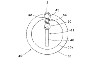
図2乃至図6に示すように、実装装置40は、上述した保持部42を有する搬送部材41と、搬送部材41の回転軸50と、回転軸50に連結軸51を介して連結され搬送部材41を回転させる駆動機構52と、回転軸50に直交して配置され搬送部材41と係合し、回転軸50の軸受けとしても機能する一対の側板55,56と、搬送部材41に貫通され搬送部材41の保持部42と回転軸50との間に配置されたバネ54と、を有している。
As shown in FIGS. 2 to 6, the mounting
なお、図2は上述したように実装装置40を示す断面図であり、図3および図4は一方の側板55を取り外した状態の実装装置40を示す側面図である。このうち図3は保持部がインターポーザー2を受け取る際の状態を示し、図4は保持部からインターポーザー2が実装される際の状態を示す。これらの図2乃至図4に示す実装装置40においては、理解しやすいように搬送部材41は1つしか示されていない。しかしながら、実際には、図1に示すように、実装装置40は複数の搬送部材41を有することが好ましい。
2 is a cross-sectional view showing the mounting
まず、このうち搬送部材41についてさらに詳述する。
First, the
図2乃至図4に示すように、搬送部材41は、インターポーザー2を保持する保持部42と、保持部42に連結され回転軸41を貫通する柱状の柱状部46と、を有している。なお、図1において右側に位置する搬送部材41から理解できるように、保持部42と柱状部46との間の連結は回動自在となっている。
As shown in FIGS. 2 to 4, the
このうち柱状部46は回転軸41に対して摺動自在となっており、これにより、保持部42と回転軸50との間の距離は変動自在となっている。
Among these, the
一方、保持部42は、両側方にそれぞれ設けられ回転自在な一対の回転コロ45,45を有している。また保持部42の上面には、図5に示すように、インターポーザー2の形状に対応した四角形からなりインターポーザー2が配置される平坦状の保持表面42aが形成されている。さらに、保持表面42aの周縁には、保持表面42aに向けて傾斜して下がる4つの傾斜面からなる位置決めガイド42bが形成されている。この位置決めガイド42bは、図6に示すように、インターポーザー2を保持表面42aに位置決めする。また、位置決めガイド42bの高さは、インターポーザー2の厚みより低くなっている(図6)。さらにまた、保持部42は保持表面42aに通ずる細穴44を有している。この細穴44についてはさらに後述する。
On the other hand, the holding
なお、図5は保持部42を示す斜視図であり、図6は図5のVI−VI線に沿った断面図である。また、図5および図6において、保持部42の移動方向を太矢印で示すとともに、図中において回転コロ45を省略している。
5 is a perspective view showing the holding
次に、側板55,56についてさらに詳述する。
Next, the
側板55,56は回転軸50に対して偏心して配置された円板からなっている。すなわち、側板55,56の中心は回転軸50からずれた位置に配置されている。側板55,56の内側(搬送部材41に対面する側)には、側板55,56の外周に沿って設けられた、したがって円周状の、段差レールからなる係合部55a,56aがそれぞれ設けられている。この係合部55a,56aは、上述した搬送部材41の保持部42の回転コロ45,45にそれぞれ係合するようになっている(図2)。
The
このような構成からなる実装装置40は、駆動機構52によって連結軸51を介して回転軸50を回転させることにより、搬送部材41を回転させるようになっている。この場合、搬送部材41の柱状部46が回転軸50に対して摺動自在となっているため、側板55,56の係合部55a,56aと搬送部材41の回転コロ45との係合により、搬送部材41の保持部42と回転軸50との間の距離が変動する。
The mounting
また、本実施の形態において、保持部42と回転軸50との間に配置されたバネ54は引っ張りバネであり、保持部42と回転軸50との間を連結している。したがって、このバネ54により、保持部42は回転軸50に接近するように付勢され、保持部42の回転コロ45は常に側板55,56の係合部55a,56a上を転がる。これにより、搬送部材41の保持部42は側板55,56の係合部55a,56aに沿って円周状に移動する。
In the present embodiment, the
さらに、本実施の形態においては、図2に示すように保持部42の下面と側板55,56の係合部55a,56aとが係合し、また、保持部42と柱状部46とは回動自在に連結されていることから、保持部42の保持表面42aは側板55,56の各外周部における接線に略沿うようにして移動する(図1)。
Further, in the present embodiment, as shown in FIG. 2, the lower surface of the holding
また、搬送部材41の保持部42と回転軸50との間の距離が変動するため、保持部42の移動速度は変化する。本実施の形態においては、図3に示す保持部42と回転軸50との間の距離が最も短くなった状態における保持部42の移動速度が第1速度となり、図4に示す保持部42と回転軸50との間の距離が最も長くなった状態における保持部42の移動速度が第2速度となるようになっている。
Further, since the distance between the holding
ところで、図1に示すように、本実施の形態において、非接触ICタグ付シート1の製造装置5は、エアーを吸引する吸引機構64と、エアーを吐出する吐出機構66とをさらに備えている。また、上述したように実装装置40は搬送部材41の保持部42の保持表面42aに通ずる細穴44を有している。この細穴44は、図示しない制御弁を介して吸引機構64と吐出機構66とに連通する。
By the way, as shown in FIG. 1, in this Embodiment, the
この場合、実装装置40は、搬送部材41の保持部42がインターポーザー2を受け取る位置から圧胴74に対面する直前までの領域Aと、保持部42が圧胴74に対面する位置における領域Bと、保持部42が圧胴74を過ぎてインターポーザー2を受け取る直前までの領域Cとを有している。
In this case, the mounting
制御弁は領域Aにある保持部42に対応する細穴44を吸引機構64に連通させるとともに吐出機構66から遮断し、領域Bにある保持部42に対応する細穴44を吐出機構66に連通させるとともに吸引機構64から遮断し、領域Cにある保持部42に対応する細穴44を吸引機構64と吐出機構66とから遮断する。
The control valve communicates the
これにより、領域Aにおいて保持部50はインターポーザー2を吸着保持して、搬送部材41が一定速度で回転することにより、吸着保持したインターポーザー2を搬送する。この場合、インターポーザー2は上述した低速の第1速度より高速の第2搬送速度で搬送される。
As a result, the holding
また、回転体40は領域Bにおいて吸着保持したインターポーザー2を解放する。すなわち、アンテナ形成済シート20上にインターポーザー2を移載(実装)する。
Further, the rotating
さらに、図4に示すように、非接触ICタグ付シートの製造装置5は、アンテナ形成済シート20のインターポーザー2が実装される部分25に接着剤等の接着材料9を供給する接着材料供給装置68と、接着材料9の性質に合わせた方法により、アンテナ形成済シート20とその上に実装されたインターポーザー2とを接合固定するとともに、アンテナ形成済シート20のアンテナ24の接点24aとインターポーザー2の拡大電極14とを電気的に接続させる固定装置70とを備えている。
Furthermore, as shown in FIG. 4, the non-contact IC tag-attached
接着材料供給装置68は、非導電性接着剤や異方性導電性接着剤を塗布するディスペンサーやスクリーン印刷機等、あるいは、テープ状の非導電性接着剤や異方性導電性接着剤をアンテナ形成済シートに貼り付ける貼着装置等が用いられる。
The adhesive
一方、固定装置70は、熱圧着機、熱圧着機、超音波接合機、あるいは溶接機等が用いられる。
On the other hand, as the fixing
次に、非接触ICタグ付シート1の製造方法について説明する。
Next, a method for manufacturing the non-contact IC tag-attached
まず、上述した、第1非導電体シート11と、この第1非導電体シート11上に配置された導電体13と、導電体13上に設けられた複数のICチップ15とを有するICチップ実装済シート10を準備する(図10)。そして、このICチップ実装済シート10をICチップ実装済シート供給装置30により、インターポーザー形成装置60に向けて低速の第1搬送速度で搬送する。
First, the above-described IC chip having the first
この場合、ICチップ実装済シート10の第1貫通孔17(図10)と第1搬送ローラー31の図示しない突起とを係合させることにより、ICチップ実装済シート10をその搬送方向に直交する幅方向に正確に位置決めすることができ、また、搬送方向への搬送量を正確に制御することができる。
In this case, by engaging the first through hole 17 (FIG. 10) of the IC chip mounted
また、搬送されるICチップ実装済シート10は上述したように第1撮影部33により撮影されるとともに、第1制御部34は第1撮影部33からの映像に基づいてICチップ実装済シート10上のICチップ15の配置ピッチが一定であるかを検査する。配置ピッチが一定でない場合には、第1制御部34は第1搬送ローラー31に信号を送り、ICチップ実装済シート10のピッチ調整を行う。これにより、ICチップ実装済シート10のICチップ15を配置された部分が常に一定時間間隔をあけてインターポーザー形成装置60に送り込まれる。なお、上述したように、第1制御部34によるICチップ実装済シート10のピッチ調整は、後述するインターポーザー形成装置60によりインターポーザー2の形成作業が行われていない間に行われる。
Further, the conveyed IC chip mounted
インターポーザー形成装置60において、回転カッター61と受けローラー62との間に送り込まれたICチップ実装済シート10はICチップ15毎に順次切断されていく。
In the
この場合、インターポーザー形成装置60には常に一定時間間隔をあけてICチップ実装済シート10のICチップ15を配置された部分が送り込まれてくる。また、外表面に等間隔をあけて切断刃61aを設けられた回転カッター61は一定の回転速度で回転する。さらに、ICチップ実装済シート10のピッチ調整は回転カッター61がICチップ実装済シート10に接触していない間に行われ、回転カッター61がICチップ実装済シート10に接触する際、ICチップ実装済シート10は常に第1搬送速度で搬送されている。
In this case, the part where the
したがって、インターポーザー形成装置60により、常に一定時間間隔をあけて導電体13からなる拡大電極14と、ICチップ15とを有するインターポーザー2が順次形成される。
Therefore, the
形成されたインターポーザー2はインターポーザー搬送コンベア77により順次実装装置40へと搬送される。このとき、インターポーザー搬送コンベア77による搬送速度は第1速度である。したがって、インターポーザー搬送コンベア77上における各インターポーザー2のICチップ15の配置ピッチは、ICチップ実装済シート10のICチップ15の配置ピッチと同一となっている。
The formed
次に、インターポーザー搬送コンベア77により搬送されるインターポーザー2は実装装置40の搬送部材41に順次受け取られる。なお、搬送部材41は駆動機構52により回転軸50を中心として一定の回転速度で回転している。
Next, the
このとき、インターポーザー2が配置される搬送部材41の保持部42は、図3に示すように回転軸50に最も接近した位置にあり、保持部42は最も遅い速度で移動する。このときの保持部42の移動速度は第1速度であり、インターポーザー2の搬送速度に同期している。したがって、保持部42は保持表面42a上に精度良くインターポーザー2を受け取ることができる。
At this time, the holding
また、保持部42には傾斜面からなる位置決めガイド42bが形成されている。したがって、保持部42は保持表面42aからずれた位置にインターポーザー2を受け取ったとしても、インターポーザー2は傾斜面からなる位置決めガイド42bをずれ落ち保持部42の中心に配置された保持表面42aへと位置決めされる。さらに、このとき保持表面42aに通ずる細穴44は吸引機構64に連通しており、インターポーザー2は保持表面に向けて吸引されるため、この位置決め効果は増大する。
The holding
このようにしてインターポーザー2は正確に位置決めされて保持部42に受け取られ、保持部42の保持表面42aに吸着保持される。
In this way, the
その後、インターポーザー2は搬送部材41の保持部42に吸着保持されたまま、アンテナ形成済シート20上まで搬送される。このとき、搬送部材41の回転コロ45は側板55,56の係合部55a,56a上を転がる。したがって、図2に示す位置からインターポーザー2をアンテナ形成済シート20上に実装する図3に示す位置に向けて回転するにつれて、保持部42はバネ54の弾発力に抗して回転軸50から離間していく。
Thereafter, the
ここで、保持部42の移動速度は回転軸50からの距離に比例する。したがって、インターポーザー2を受け取って搬送しアンテナ形成済シート2上へ実装するまで、保持部42の移動速度は次第に上昇していく。すなわち、保持部42の移動速度は、インターポーザー2を受け取る際の低速の第1速度からインターポーザー2を実装する際の高速の第2速度まで昇速する。また、各保持部42の移動速度の昇速に伴い、図1に示すように、インターポーザー2を受け取る位置からアンテナ形成済シート20上へ実装する位置に向け、複数の保持部42にそれぞれ吸着保持されたインターポーザー2同士間の間隔は広がっていく。
Here, the moving speed of the holding
このように昇速されるインターポーザー2は、側板55,56の周縁に沿って搬送される。このとき、インターポーザー2は案内ガイド72によりスムースに案内されて搬送されるので、インターポーザー2が加速されながら搬送されたとしても保持部42からずれてしまうことを防止することができる。
The
ところで、ICチップ実装済シート10からインターポーザー2が形成され、インターポーザー2が搬送される間、同時に、第2非導電体シート21と、この第2非導電体シート21上に設けられた複数のアンテナ24とを有するアンテナ形成済シート20が準備される。そして、このアンテナ形成済シート20は被搭載体供給装置35により、実装装置40と圧胴74との間に向けて高速の第2速度で搬送される。
By the way, while the
この場合、アンテナ形成済シート20の第2貫通孔27(図11)と第2搬送ローラー36の図示しない突起とを係合させることにより、アンテナ形成済シート20をその搬送方向に直交する幅方向に正確に位置決めすることができ、また、搬送方向への搬送量を正確に制御することができる。
In this case, by engaging the second through-hole 27 (FIG. 11) of the antenna-formed
また、搬送されるアンテナ形成済シート20は上述したように第2撮影部38により撮影されるとともに、第2制御部39は第2撮影部38から映像に基づいてアンテナ形成済シート20上のアンテナ24のインターポーザー2を実装される部分の配置ピッチが一定であるかを検査する。配置ピッチが一定でない場合には、第2制御部39は第2搬送ローラー36に信号を送り、アンテナ形成済シート20のピッチ調整を行う。これにより、インターポーザーを実装される部分25が常に一定時間間隔をあけて実装装置40と圧胴74との間に送り込まれる。なお、上述したように、第2制御部39によるアンテナ形成済シート20のピッチ調整は、後述するインターポーザー2の実装作業が行われていない間に行われる。
The conveyed antenna-formed
なお、本実施の形態においては、図1に示すように、アンテナ形成済シート20のインターポーザーを実装される部分25には、接着材料供給装置68により接着材料9が供給される。
In the present embodiment, as shown in FIG. 1, the
このようにして、接着材料9を供給されたアンテナ形成済シート20が実装装置40と圧胴74との間を搬送される。
In this way, the antenna-formed
この場合、アンテナ形成済シート20のインターポーザーを実装される部分25が常に一定時間間隔をあけて実装装置40と圧胴74との間に送り込まれる。また、アンテナ形成済シート20のインターポーザーを実装される部分25が実装装置40と圧胴74との間を通過する際、アンテナ形成済シート20の搬送速度は常に実装装置40の搬送部材41の保持部42の移動速度と同一の第2速度である。
In this case, the
したがって、インターポーザー2の搬送速度と同一の第2速度で搬送されるアンテナ形成済シート20のインターポーザーを実装される部分25上に、実装装置40の保持部42に保持されて搬送されるインターポーザー2を順次対面させるようにすることができる。
Accordingly, the
また、このとき、インターポーザー2を吸着保持する保持部42の保持表面42aに通ずる細穴44は、図示しない制御弁により吸引機構64から遮断されるとともに吐出機構66に連通する。したがって、インターポーザー2は保持部42から解放されるとともに、吐出機構66から吐出されるエアーによりアンテナ形成済シート20に向けて押圧される。これにより、インターポーザー2が確実にアンテナ形成済シート20上に実装され、接着材料9を介して固定される。
At this time, the
このようにして、インターポーザー2がアンテナ形成済シート20上に一定時間間隔をあけて順次実装されていく。その後、固定装置70により、インターポーザー2の拡大電極14とアンテナ形成済シート20のアンテナ24の接点24aとが電気的に接合される。
In this way, the
なお、本実施の形態においては、アンテナ形成済シート2のアンテナ24側に接着材料9を塗布する例を示したが、これに限定されず、インターポーザー2の拡大電極14側に接着材料9を塗布するようにしてもよい。
In the present embodiment, the example in which the
以上のようにして、アンテナ形成済シート20とインターポーザー2とを有する非接触ICタグ付シート1が製造される。このような非接触ICタグ付シート1はアンテナ24毎に切断または打ち抜きされ、あるいは、一旦ロール状に巻き取られた後に必要に応じてアンテナ24毎に切断または打ち抜きされ、非接触ICタグが得られる。
As described above, the non-contact IC tag-attached
以上のように本実施の形態によれば、第1速度で搬送されるICチップ実装済シート10から一定時間間隔をあけてインターポーザー2を順次連続的に作製し、作製されたインターポーザー2を一定の回転速度で回転する実装装置40の搬送部材41により順次受け取って搬送し、第2速度で搬送されるアンテナ形成済シート20上へ順次実装していくことにより、非接触ICタグ付シート1を製造する。
As described above, according to the present embodiment, the
ここで、本実施の形態による実装装置40の搬送部材41は一定速度で回転する一方で、搬送部材41のインターポーザー2を保持する保持部42はその回転軸50からの距離を変動し、移動速度を増減させることができる。したがって、インターポーザー2を受け取る際、ICチップ実装済シート10の搬送速度に同期させて保持部42を移動させることができるとともに、インターポーザー2をアンテナ形成済シート20上へ実装する際、ICチップ実装済シート10の搬送速度よりも速いアンテナ形成済シート20の搬送速度に同期させて保持部42を移動させることができる。
Here, while the
これにより、実装装置40は、インターポーザー2を正確に位置決めした状態で搬送部材41の保持部42上へ受け取ることができ、さらに、インターポーザー2を正確にアンテナ形成済シート20上へ配置することもできる。これにより、インターポーザーを精度良く実装することができる。
Thereby, the mounting
この場合、保持部42上には位置決めガイド42bが形成されていることから、インターポーザー2を保持部42の保持表面42a上へさらに正確に位置決めすることができる。
In this case, since the
また、通常、ICチップ実装済シート10上のICチップ15の配置間隔、すなわち、インターポーザーを形成する部分の間隔に比べ、アンテナ形成済シート20上のアンテナの配置間隔、すなわち、インターポーザーを実装される部分25の間隔は広くなっており、両間隔は一致していない。このため、ICチップ実装済シート10を打ち抜きまたは切断してインターポーザー2を連続的に順次作製し、アンテナ形成済シート上に連続的に実装する場合、ICチップ実装済シート10とアンテナ形成済シート20の搬送速度は異なる。しかしながら、本実施の形態によれば、上述したように、保持部42がインターポーザー2を保持した状態で移動速度を変更することにより、ICチップ実装済シート10とアンテナ形成済シート20との両者を間欠的に搬送する代わりに、両者を一定速度で搬送するとともにこれらの搬送速度に保持部42をそれぞれ同期させ、アンテナ形成済シート20へインターポーザー2を連続的かつスムースに実装することができる。
Further, the antenna arrangement interval on the antenna-formed
また、実装装置40の搬送部材41は駆動機構52により一定の回転速度で回転させられるだけであり、搬送部材41の保持部42と回転軸50との距離は、単に保持部42の回転コロ45と側板55,56の係合部55a,56aとを係合させることにより制御されているだけである。したがって、実装装置40の制御は非常に単純かつ容易である。
Further, the
これらのことから、非接触ICタグ付シートの製造装置5全体を単純かつ容易に制御することができ、これにより、非接触ICタグ付シート1を単純かつ容易に製造することができる。
From these, the
さらに、ICチップ実装済シート10上のICチップ15の配置間隔と、アンテナ形成済シート20上のアンテナの配置間隔との組合せを変更して非接触ICタグ付シートを製造する場合、第1速度と第2速度との比を変更する必要が生じる。この場合、実装装置40に用いられる側板55,56の形状、さらに詳しくは側板55,56の係合部55a,56aの形状を変更することにより、保持部42の移動速度を変更することができる。このように、異なる形状からなる側板55,56を多数準備しておくことにより、実装装置40全体を交換することなく異なる非接触ICタグ付シート1を製造することができる。
Furthermore, when manufacturing a sheet with a non-contact IC tag by changing the combination of the arrangement interval of the IC chips 15 on the IC chip-mounted
なお、本実施の形態において、実装装置40の搬送部材41の保持部42と、保持部42に受け取られるインターポーザー2の搬送速度とを同期させる例を示したが、これに限られない。インターポーザー2の搬送速度より速い速度で移動しながら、保持部42がインターポーザー2を受け取るようにしてもよい。あるいは、保持部42の移動方向に沿って停止した状態で供給されるインターポーザー2を保持部42が受け取るようにしてもよい。
In the present embodiment, the example in which the holding
この場合、非接触ICタグ付シートの製造装置5全体の制御がさらに容易となる。また、ICチップ15の配置間隔の異なるICチップ実装済シート10から非接触ICタグ付シート1を製造する際にも、同一の実装装置40を用いることができ、これにより、実装装置40の汎用性を増すことができる。
In this case, the control of the
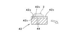
なお、このような方法で保持部42がインターポーザー2を受け取る場合、上述した保持部42に代えて図7および図8に示す保持部42を用いることが好ましい。図7および図8に示す保持部42の位置決めガイド42cは、保持部42の移動方向前方側が開口するとともに、前方側において幅広となっている。
In addition, when the holding |
ここで、図7は保持部42を示す斜視図であり、図8は図7のVIII−VIII線に沿った断面図である。また、図7および図8において、保持部42の移動方向を太矢印で示すとともに、図中において回転コロ45を省略している。また、図7および図8に示す保持部42は、図5および図6に示す保持部42と位置決めガイド42cの形状が異なるだけであり、他は略同一である。同一部分には同一符号を付すとともに詳細な説明は省略する。
7 is a perspective view showing the holding
さらにまた、本実施の形態において、回転カッター61を有するインターポーザー形成装置60を用いた例を示したが、これに限られない。搬送されるICチップ実装済シート10を一定時間間隔あけてインターポーザー2を順次形成することができる打ち抜き機や切断機であればよい。
Furthermore, in this Embodiment, although the example using the
さらに、本実施の形態において、インターポーザー形成装置60は回転カッター61と受けローラー62とを有し、インターポーザー形成装置60により形成されたインターポーザー2はインターポーザー搬送コンベア77により実装装置40まで搬送される例を示したが、これに限られない。実装装置40をインターポーザー形成装置60の回転カッター61に対向した位置へ配置し、実装装置40の搬送部材41の保持部42を回転カッター61の受けとして機能させるようにしてもよい。この場合、ICチップ実装済シート10から分離されたインターポーザー2はそのまま搬送部材41の保持部42に保持される。このように構成した非接触ICタグ付シートの製造装置5においては、当然に、上述したインターポーザー形成装置60の受けローラー62と、インターポーザー搬送コンベア77とを省略することができる。これにより、非接触ICタグ付シートの製造装置5をさらに単純な構成とすることができ、その制御もさらに単純かつ容易にすることができる。
Further, in the present embodiment, the
またさらに、本実施の形態において、被搭載体をアンテナ形成済シート20とし、アンテナ形成済シート20に一定配置間隔をあけて形成されたアンテナ24上にインターポーザー2を順次実装してなる非接触ICタグ付シート1を製造する例を示したが、当然にこれに限られない。上述したように、インターポーザー2自体を非接触ICタグとして用いる場合、断裁されてカードを構成するプラスチックシートや、断裁されて包装紙を構成するビニルシート等が、被搭載体として用いられ得る。そして、プラスチックシートやビニルシート等を被搭載体30として用いた場合にも、本実施の形態による製造方法および製造装置を適用して非接触ICタグ付シート1を製造することができる。
Furthermore, in the present embodiment, the mounted body is the antenna-formed
1 非接触ICタグ付シート
2 インターポーザー
5 非接触ICタグ付シートの製造装置
9 接着材料
10 ICチップ実装済シート
11 第1非導電体シート
13 導電体
14 拡大電極
15 ICチップ
20 アンテナ形成済シート(被搭載体)
21 第2非導電体シート
24 アンテナ
25 インターポーザーを実装される部分
30 ICチップ実装済シート供給装置
34 第1制御部
35 被搭載体供給装置
40 実装装置
41 搬送部材
42 保持部
42b,42c 位置決めガイド
46 柱状部
50 回転軸
55,56 側板
55a,56a 係合部
60 インターポーザー形成装置
64 吸引機構
66 吐出機構
68 接着材料供給装置
70 固定装置
72 案内ガイド
74 圧胴
DESCRIPTION OF
21
Claims (25)
第1速度で搬送されるICチップ実装済シートをICチップ毎に打ち抜きまたは切断して、導電体からなる拡大電極と、ICチップとを有するインターポーザーを順次形成する工程と、
形成されたインターポーザーを、一定の回転速度で回転する搬送部材に保持させて搬送する工程と、
シート状の被搭載体を第2速度で搬送して供給する工程と、
第2速度で搬送される被搭載体上に、搬送部材により搬送されるインターポーザーを順次実装する工程と、を備え、
搬送部材のインターポーザーを保持する保持部と搬送部材の回転軸との間の距離が変動し、インターポーザーを受け取る際に保持部は第1速度で移動し、インターポーザーを実装する際に保持部は第2速度で移動することを特徴とする非接触ICタグ付シートの製造方法。 An IC chip mounted sheet having a first non-conductor sheet, a conductor disposed on the first non-conductor sheet, and a plurality of IC chips provided on the conductor is conveyed at a first speed. Supplying the process,
Punching or cutting the IC chip mounted sheet conveyed at the first speed for each IC chip to sequentially form an interposer having an enlarged electrode made of a conductor and an IC chip;
A step of transporting the formed interposer while being held by a transporting member that rotates at a constant rotational speed;
A step of transporting and supplying a sheet-like mounted body at a second speed;
A step of sequentially mounting an interposer transported by a transport member on a mounted body transported at a second speed,
The distance between the holding part that holds the interposer of the conveying member and the rotation axis of the conveying member fluctuates, the holding part moves at the first speed when receiving the interposer, and the holding part when mounting the interposer Moves at a second speed, a method for producing a sheet with a non-contact IC tag.
シート状の被搭載体を第1速度より速い第2速度で搬送して供給する被搭載体供給装置と、
搬送されるICチップ実装済シートをICチップ毎に打ち抜きまたは切断して、導電体からなる拡大電極と、ICチップとを有するインターポーザーを形成するインターポーザー形成装置と、
インターポーザーを保持する保持部を有して回転自在な搬送部材を有し、インターポーザーを受け取って搬送し被搭載体上に実装する実装装置と、を備え、
実装装置の搬送部材の保持部と搬送部材の回転軸との間の距離が変動自在であることを特徴とする非接触ICタグ付シートの製造装置。 An IC chip mounted sheet having a first non-conductor sheet, a conductor disposed on the first non-conductor sheet, and a plurality of IC chips provided on the conductor is conveyed at a first speed. IC chip mounted sheet supply device for supplying
A mounted body supply apparatus for transporting and supplying a sheet-shaped mounted body at a second speed higher than the first speed;
An interposer forming apparatus for punching or cutting the IC chip mounted sheet to be conveyed for each IC chip to form an interposer having an enlarged electrode made of a conductor and an IC chip;
A holding device for holding the interposer, a rotatable transport member, a mounting device for receiving and transporting the interposer and mounting it on the mounted body;
An apparatus for manufacturing a sheet with a non-contact IC tag, wherein a distance between a holding portion of a conveying member of the mounting apparatus and a rotation shaft of the conveying member is freely variable.
制御部は、ICチップ実装済シートのICチップを配置された部分が一定時間間隔をあけてインターポーザー形成装置に送り込まれるよう、ICチップ実装済シートの供給を制御することを特徴とする請求項9乃至15のいずれか一項に記載の非接触ICタグ付シートの製造装置。 The IC chip mounted sheet supply device has a control unit that controls the supply of the IC chip mounted sheet,
The control unit controls the supply of the IC chip mounted sheet so that a portion of the IC chip mounted sheet on which the IC chip is arranged is sent to the interposer forming apparatus at a predetermined time interval. The manufacturing apparatus of the sheet | seat with a non-contact IC tag as described in any one of 9 thru | or 15.
吸引機構により、インターポーザーは搬送部材の保持部に吸着保持されることを特徴とする請求項9乃至17のいずれか一項に記載の非接触ICタグ付シートの製造装置。 A suction mechanism that communicates with the carrying member of the mounting apparatus;
The non-contact IC tag-attached sheet manufacturing apparatus according to any one of claims 9 to 17, wherein the interposer is sucked and held by the holding portion of the transport member by the suction mechanism.
吐出機構により、インターポーザーは被搭載体に向けて押圧されて実装されることを特徴とする請求項9乃至18のいずれか一項に記載の非接触ICタグ付シートの製造装置。 It further comprises a discharge mechanism that communicates with the conveying member of the mounting device,
The apparatus for manufacturing a sheet with a non-contact IC tag according to any one of claims 9 to 18, wherein the interposer is mounted by being pressed toward the mounted body by the discharge mechanism.
被搭載体は実装装置と圧胴との間へ送り込まれることを特徴とする請求項9乃至19のいずれか一項に記載の非接触ICタグ付シートの製造装置。 It further comprises an impression cylinder arranged facing the mounting device,
The apparatus for manufacturing a sheet with a non-contact IC tag according to any one of claims 9 to 19, wherein the mounted body is fed between the mounting apparatus and the impression cylinder.
供給されるインターポーザーを、一定の回転速度で回転する搬送部材に保持させて搬送する工程と、
シート状の被搭載体を一定の速度で搬送して供給する工程と、
搬送される被搭載体上に、搬送部材により搬送されるインターポーザーを順次実装する工程と、を備え、
搬送部材のインターポーザーを保持する保持部と搬送部材の回転軸との間の距離が変動し、インターポーザーを実装する際に、保持部は被搭載体の搬送速度と同一の速度で移動することを特徴とする被搭載体へインターポーザーを実装するインターポーザーの実装方法。 Sequentially supplying an interposer having an enlarged electrode and an IC chip;
A step of transporting the supplied interposer by holding it on a transporting member that rotates at a constant rotational speed;
A step of transporting and supplying a sheet-like mounted body at a constant speed;
A step of sequentially mounting an interposer conveyed by a conveying member on a substrate to be conveyed; and
The distance between the holding part that holds the interposer of the conveying member and the rotation axis of the conveying member fluctuates, and when the interposer is mounted, the holding part must move at the same speed as the conveying speed of the mounted object. An interposer mounting method for mounting an interposer on a mounted body characterized by the above.
インターポーザーを受け取って保持する保持部を有し回転自在な搬送部材を備え、
搬送部材の保持部と搬送部材の回転軸との間の距離が変動自在であることを特徴とするインターポーザーの実装装置。 An interposer mounting device that mounts an interposer having an enlarged electrode and an IC chip on a sheet-like mounted object that is conveyed at a constant speed,
A holding member for receiving and holding the interposer and a rotatable conveying member;
An interposer mounting apparatus characterized in that a distance between a holding part of a conveying member and a rotation axis of the conveying member is variable.
Priority Applications (1)
| Application Number | Priority Date | Filing Date | Title |
|---|---|---|---|
| JP2004228375A JP2006048366A (en) | 2004-08-04 | 2004-08-04 | Non-contact IC tag sheet manufacturing method, non-contact IC tag sheet manufacturing apparatus, interposer mounting method, and interposer mounting apparatus |
Applications Claiming Priority (1)
| Application Number | Priority Date | Filing Date | Title |
|---|---|---|---|
| JP2004228375A JP2006048366A (en) | 2004-08-04 | 2004-08-04 | Non-contact IC tag sheet manufacturing method, non-contact IC tag sheet manufacturing apparatus, interposer mounting method, and interposer mounting apparatus |
Publications (1)
| Publication Number | Publication Date |
|---|---|
| JP2006048366A true JP2006048366A (en) | 2006-02-16 |
Family
ID=36026843
Family Applications (1)
| Application Number | Title | Priority Date | Filing Date |
|---|---|---|---|
| JP2004228375A Withdrawn JP2006048366A (en) | 2004-08-04 | 2004-08-04 | Non-contact IC tag sheet manufacturing method, non-contact IC tag sheet manufacturing apparatus, interposer mounting method, and interposer mounting apparatus |
Country Status (1)
| Country | Link |
|---|---|
| JP (1) | JP2006048366A (en) |
Cited By (1)
| Publication number | Priority date | Publication date | Assignee | Title |
|---|---|---|---|---|
| JP2012512477A (en) * | 2008-12-17 | 2012-05-31 | エフシーアイ | IC non-contact communication device manufacturing method |
-
2004
- 2004-08-04 JP JP2004228375A patent/JP2006048366A/en not_active Withdrawn
Cited By (1)
| Publication number | Priority date | Publication date | Assignee | Title |
|---|---|---|---|---|
| JP2012512477A (en) * | 2008-12-17 | 2012-05-31 | エフシーアイ | IC non-contact communication device manufacturing method |
Similar Documents
| Publication | Publication Date | Title |
|---|---|---|
| CN101496038B (en) | High-speed rfid circuit placement method and device | |
| JP4551122B2 (en) | RFID label affixing device | |
| JP4734857B2 (en) | IC chip assembly manufacturing apparatus | |
| US20080295318A1 (en) | Method and Device for Continuously Producing Electronic Film Components and an Electronic Film Component | |
| EP1746636A1 (en) | IC chip mounting method | |
| JP5386117B2 (en) | RF tag label tape manufacturing equipment | |
| US20070056683A1 (en) | Strap/inlay insertion method and apparatus | |
| WO2005064667A1 (en) | Ic chip mounting body manufacturing method and manufacturing device | |
| JP4978832B2 (en) | Non-contact communication member manufacturing method, non-contact communication member manufacturing apparatus, interposer manufacturing method, and interposer manufacturing apparatus | |
| CN104441783B (en) | Apparatus for punching labels with cooperating punching belts | |
| JP4664960B2 (en) | Label sheet making device | |
| JP5023669B2 (en) | IC chip assembly manufacturing apparatus | |
| JP2006048366A (en) | Non-contact IC tag sheet manufacturing method, non-contact IC tag sheet manufacturing apparatus, interposer mounting method, and interposer mounting apparatus | |
| JP2016147361A (en) | Cutting device for laminated sheet with adhesive layer and cutting blade unit used in the cutting device | |
| JP4802548B2 (en) | IC chip assembly manufacturing apparatus | |
| JP2006048363A (en) | Manufacturing method and manufacturing apparatus for sheet with non-contact IC tag | |
| JP2021142630A (en) | Cutting transfer device and label manufacturing device and cutting transfer method and label manufacturing method | |
| JP2006252170A (en) | IC chip assembly manufacturing apparatus | |
| JP4743583B2 (en) | Sheet with IC tag | |
| JP4390180B2 (en) | Method and apparatus for laminating interposer substrate | |
| JP2006039659A (en) | Non-contact data carrier member mounting method and apparatus | |
| JP4526878B2 (en) | Non-contact data carrier member mounting method and apparatus | |
| JP2006048339A (en) | Manufacturing method and manufacturing apparatus for sheet with non-contact IC tag | |
| JP5324254B2 (en) | IC label production equipment | |
| JP2006048361A (en) | Manufacturing method and manufacturing apparatus for sheet with non-contact IC tag |
Legal Events
| Date | Code | Title | Description |
|---|---|---|---|
| A300 | Withdrawal of application because of no request for examination |
Free format text: JAPANESE INTERMEDIATE CODE: A300 Effective date: 20071106 |