JP2005523782A - Needleless lure access connector - Google Patents
Needleless lure access connector Download PDFInfo
- Publication number
- JP2005523782A JP2005523782A JP2004500967A JP2004500967A JP2005523782A JP 2005523782 A JP2005523782 A JP 2005523782A JP 2004500967 A JP2004500967 A JP 2004500967A JP 2004500967 A JP2004500967 A JP 2004500967A JP 2005523782 A JP2005523782 A JP 2005523782A
- Authority
- JP
- Japan
- Prior art keywords
- septum
- housing
- slit
- needleless
- intermediate portion
- Prior art date
- Legal status (The legal status is an assumption and is not a legal conclusion. Google has not performed a legal analysis and makes no representation as to the accuracy of the status listed.)
- Pending
Links
Images


Classifications
-
- A—HUMAN NECESSITIES
- A61—MEDICAL OR VETERINARY SCIENCE; HYGIENE
- A61M—DEVICES FOR INTRODUCING MEDIA INTO, OR ONTO, THE BODY; DEVICES FOR TRANSDUCING BODY MEDIA OR FOR TAKING MEDIA FROM THE BODY; DEVICES FOR PRODUCING OR ENDING SLEEP OR STUPOR
- A61M39/00—Tubes, tube connectors, tube couplings, valves, access sites or the like, specially adapted for medical use
- A61M39/22—Valves or arrangement of valves
- A61M39/26—Valves closing automatically on disconnecting the line and opening on reconnection thereof
-
- A—HUMAN NECESSITIES
- A61—MEDICAL OR VETERINARY SCIENCE; HYGIENE
- A61M—DEVICES FOR INTRODUCING MEDIA INTO, OR ONTO, THE BODY; DEVICES FOR TRANSDUCING BODY MEDIA OR FOR TAKING MEDIA FROM THE BODY; DEVICES FOR PRODUCING OR ENDING SLEEP OR STUPOR
- A61M39/00—Tubes, tube connectors, tube couplings, valves, access sites or the like, specially adapted for medical use
- A61M39/02—Access sites
- A61M39/04—Access sites having pierceable self-sealing members
- A61M39/045—Access sites having pierceable self-sealing members pre-slit to be pierced by blunt instrument
-
- A—HUMAN NECESSITIES
- A61—MEDICAL OR VETERINARY SCIENCE; HYGIENE
- A61J—CONTAINERS SPECIALLY ADAPTED FOR MEDICAL OR PHARMACEUTICAL PURPOSES; DEVICES OR METHODS SPECIALLY ADAPTED FOR BRINGING PHARMACEUTICAL PRODUCTS INTO PARTICULAR PHYSICAL OR ADMINISTERING FORMS; DEVICES FOR ADMINISTERING FOOD OR MEDICINES ORALLY; BABY COMFORTERS; DEVICES FOR RECEIVING SPITTLE
- A61J1/00—Containers specially adapted for medical or pharmaceutical purposes
- A61J1/14—Details; Accessories therefor
- A61J1/1406—Septums, pierceable membranes
-
- A—HUMAN NECESSITIES
- A61—MEDICAL OR VETERINARY SCIENCE; HYGIENE
- A61M—DEVICES FOR INTRODUCING MEDIA INTO, OR ONTO, THE BODY; DEVICES FOR TRANSDUCING BODY MEDIA OR FOR TAKING MEDIA FROM THE BODY; DEVICES FOR PRODUCING OR ENDING SLEEP OR STUPOR
- A61M39/00—Tubes, tube connectors, tube couplings, valves, access sites or the like, specially adapted for medical use
- A61M39/22—Valves or arrangement of valves
- A61M39/26—Valves closing automatically on disconnecting the line and opening on reconnection thereof
- A61M2039/266—Valves closing automatically on disconnecting the line and opening on reconnection thereof where the valve comprises venting channels, e.g. to insure better connection, to help decreasing the fluid space upon disconnection, or to help the fluid space to remain the same during disconnection
Landscapes
- Health & Medical Sciences (AREA)
- Heart & Thoracic Surgery (AREA)
- Animal Behavior & Ethology (AREA)
- General Health & Medical Sciences (AREA)
- Anesthesiology (AREA)
- Biomedical Technology (AREA)
- Hematology (AREA)
- Life Sciences & Earth Sciences (AREA)
- Pulmonology (AREA)
- Engineering & Computer Science (AREA)
- Public Health (AREA)
- Veterinary Medicine (AREA)
- Infusion, Injection, And Reservoir Apparatuses (AREA)
- Measurement And Recording Of Electrical Phenomena And Electrical Characteristics Of The Living Body (AREA)
- Medical Preparation Storing Or Oral Administration Devices (AREA)
- Saccharide Compounds (AREA)
- Pharmaceuticals Containing Other Organic And Inorganic Compounds (AREA)
Abstract
ハウジング(10)に配置された隔壁(20)を有するニードルレスルアーアクセスコネクタが開示される。隔壁(20)は、断面を有する近位部(21)と、近位部(21)の断面より小さい断面を有する中間部(22)と、遠位部(23)とを有する。縦のスリット(25)が隔壁(20)を通過して近位部(21)から遠位部(23)まで伸びる。隔壁(20)とハウジング(10)とは、コネクタが雄ルアーテーパによってアクセスされたとき、隔壁が回転されたりハウジング(10)から取り出されたりしないように、設計されている。また、隔壁(20)とハウジング(10)とは、遠位部(23)の位置においてスリット(25)を閉じるよう付勢するように設計され、雄ルアーコネクタは遠位部(23)を完全に通過して伸びる必要がない。最後に、隔壁(20)とハウジング(10)とは、雄ルアーテーパによってアクセスされたときコネクタ内のデッドスペースの大きさを最小にするように、設計されている。A needleless luer access connector having a septum (20) disposed in the housing (10) is disclosed. The septum (20) has a proximal portion (21) having a cross-section, an intermediate portion (22) having a smaller cross-section than the cross-section of the proximal portion (21), and a distal portion (23). A longitudinal slit (25) extends through the septum (20) and extends from the proximal portion (21) to the distal portion (23). The septum (20) and housing (10) are designed so that when the connector is accessed by a male luer taper, the septum is not rotated or removed from the housing (10). Also, the septum (20) and the housing (10) are designed to bias the slit (25) to close at the position of the distal portion (23), and the male luer connector completely extends the distal portion (23). There is no need to pass through and stretch. Finally, the septum (20) and the housing (10) are designed to minimize the amount of dead space in the connector when accessed by the male luer taper.
Description
本発明は、医者(clinician)がシャープなニードルを使用すること無く流体流れラインにアクセスすることを許容する、一般にルアーアクセス装置と称されるニードルレスコネクタに関する。特に、本発明は、例えば注射器等の医療機器の標準的な雄ルアーテーパ(male luer taper)によって開放され得るニードルレスルアーアクセスコネクタ(needleless luer access connector)に関する。雄ルアーテーパによるコネクタの貫通は、流体流れがコネクタを通過するのを許容する。雄ルアーテーパがコネクタから取り外されたとき、それは閉止して流体流れが通過するのを阻止する。 The present invention relates to a needleless connector, commonly referred to as a luer access device, that allows a clinician to access a fluid flow line without using a sharp needle. In particular, the present invention relates to a needleless luer access connector that can be opened by a standard male luer taper of a medical device such as a syringe. The penetration of the connector by the male luer taper allows fluid flow to pass through the connector. When the male luer taper is removed from the connector, it closes and prevents fluid flow from passing.
患者の治療においては、流体が、様々な容器と血管(IV)ラインとの間で、或いはIVカテーテルを通じて患者に、移送される。この移送は、患者への細菌の進入を防止するための閉システムによって行われる。患者の血管系へのアクセスを得るためにIVカテーテルが患者に挿入されているこの種の治療の過程において、薬剤等の他の流体をカテーテルを通じて患者に導入し、又は血液ガス若しくは他の分析のため患者から血液を抜く必要がある場合がある。このような血液抽出又は患者への注入は、IVライン、塩類ウェル(saline well)、動脈ライン、又は血液透析ラインを通じてのものである。従来、流体が開口から流出するのを阻止して閉システムを保つため、ゴム又はシリコンの隔壁が、カテーテルの開口又はIVラインをカバーするのに用いられていた。医者は、シャープなニードルを注射器から隔壁に挿入することにより開口にアクセスし得る。これは、医者が、注射器から患者に流体を導入すること、又は患者から注射器内に流体を抜き取ることを許容する。隔壁は、ニードルが引き抜かれた後、再シールを行って流体の逆流を防ぐ。 In patient treatment, fluid is transferred to the patient between various containers and blood vessel (IV) lines or through IV catheters. This transfer is performed by a closed system to prevent bacteria from entering the patient. In the course of this type of treatment where an IV catheter is inserted into the patient to gain access to the patient's vasculature, other fluids such as drugs are introduced into the patient through the catheter, or blood gas or other analysis Therefore, it may be necessary to draw blood from the patient. Such blood extraction or patient infusion is through an IV line, a saline well, an arterial line, or a hemodialysis line. Traditionally, rubber or silicone septa have been used to cover catheter openings or IV lines to prevent fluid from exiting the openings and maintaining a closed system. The physician can access the opening by inserting a sharp needle from the syringe into the septum. This allows the physician to introduce fluid from the syringe into the patient or to draw fluid from the patient into the syringe. The septum re-seals after the needle is withdrawn to prevent fluid backflow.
近年、患者の血液又は他の流体による医者の汚染と、そのような「血液汚染された鋭利物(blood contaminated sharp)」が即座に廃棄されなければならないという認識とに関する多くの関心がある。この関心は、例えば後天性免疫不全症候群(「AIDS」)や肝炎等の現在不治で致命的な病気の広告に起因して高まっている。この病気は、感染者から他人への体液の交換により移る可能性がある。結局、AIDSや肝炎にかかった人の体液との接触は、そのような病気を健康な人に移すのを防止するために回避されなければならない。仮にニードルが、AIDS又は肝炎感染者に連通するIVラインにアクセスするために用いられると、ニードルは病気の移動のための輸送手段となる。医者は「血液汚染された鋭利物」を正しく取り扱う必要性に気付いているけれども、残念ながら、例えば緊急事態又は不注意若しくは無視の結果として、ある医療環境においては、汚染されたニードルによる刺傷が依然として起こる。「血液汚染された鋭利物」による不慮の刺傷の問題の結果として、シャープニードルの使用を回避する様々なコネクタの開発に多大な努力が費やされている。 In recent years, there has been much interest in the physician's contamination of the patient's blood or other fluids and the perception that such “blood contaminated sharps” must be immediately discarded. This interest has increased due to advertising of currently incurable and fatal diseases such as acquired immune deficiency syndrome (“AIDS”) and hepatitis. The disease can be transferred by exchanging body fluids from an infected person to another person. Eventually, contact with body fluids of people with AIDS or hepatitis must be avoided to prevent the transfer of such illnesses to healthy people. If the needle is used to access an IV line communicating with an AIDS or hepatitis infected person, the needle becomes a vehicle for disease transfer. Although doctors have realized the need to properly handle “blood-contaminated sharps”, unfortunately, in some medical settings, for example, as a result of an emergency or carelessness or neglect, a sting with a contaminated needle is still Occur. As a result of inadvertent stings due to “blood-contaminated sharps”, great efforts have been expended in developing various connectors that avoid the use of sharp needles.
あるタイプのニードルレスコネクタは、長手方向に可動のダイアフラムを含み、これは、コネクタに固定された内部カニューレを通じて流体の流れをコントロールする。この内部カニューレはコネクタを通ずる流体流れ通路を区画する。可動ダイアフラムは、スプリング又は他の可撓性部材等の付勢部材と協働する。付勢部材は、可動ダイアフラムの頂部を、コネクタに対する入口又は近位の開口に向けて付勢する。開口は典型的に雌ルアー接続の形態にある。可動ダイアフラムがコネクタの入口に隣接されると、可動ダイアフラムは内部カニューレへの開口を塞いでコネクタを流体流れに対し閉止する。医者が、注射器等の他の医療機器の雄ルアーテーパをコネクタの雌ルアーテーパに挿入すると、コネクタが開放され得る。これがなされるとき、可動ダイアフラムはハウジング内に押し込まれ、これにより内部カニューレが、可動ダイアフラムに予め形成されているスリットを挿通し、コネクタを通ずる流体流れ通路を提供する。 One type of needleless connector includes a longitudinally movable diaphragm that controls fluid flow through an internal cannula secured to the connector. The internal cannula defines a fluid flow passage through the connector. The movable diaphragm cooperates with a biasing member such as a spring or other flexible member. The biasing member biases the top of the movable diaphragm toward the inlet or proximal opening to the connector. The opening is typically in the form of a female luer connection. When the movable diaphragm is adjacent to the inlet of the connector, the movable diaphragm closes the opening to the internal cannula and closes the connector against fluid flow. When the doctor inserts the male luer taper of another medical device such as a syringe into the female luer taper of the connector, the connector can be opened. When this is done, the movable diaphragm is pushed into the housing so that the inner cannula provides a fluid flow passage through the connector through the pre-formed slit in the movable diaphragm.
これらコネクタはこれらの予定されている機能に従ってほぼ作動するけれども、これらコネクタは改良されることができる。内部カニューレの先端が可動ダイアフラムに係合するとき、内部カニューレは可動ダイアフラムの芯を抜こうとする。これは、可動ダイアフラムの一部を破壊し、患者に導入する可能性がある。また、この可動ダイアフラムの芯抜きは、コネクタの流体漏れを促進すると共に、細菌の進入のための通路に帰結する可能性がある。最後に、内部カニューレの先端を越えて可動ダイアフラムを動かすのに必要な力は、極めて高く、その作動を困難とし、雄ルアーテーパをコネクタから押し出そうとする実質的な反動力に帰結する。
内部カニューレを有するコネクタに対する可能な改良は、ダイアフラムを通ずる成形された開口を有し、コネクタを通ずる流体の流れをコントロールする、長手方向に可動のダイアフラムを含むコネクタである。ある付勢部材が可動ダイアフラムを装置の入口に向けて付勢する。この位置で、可動ダイアフラムの近位部は、コネクタの入口開口を区画し且つ成形された開口を閉じるように付勢するハウジングの側壁によって半径方向に付勢される。これはコネクタを通ずる流体流れを阻止する。医者が注射器の雄ルアーテーパをコネクタの入口に挿入すると、可動ダイアフラムはコネクタ内に移動されて、可動ダイアフラムの近位部に接触しない領域に移動される。これは、ダイアフラムの近位部が、その付勢されない状態に戻り、成形された開口が開放位置に位置され、コネクタを通ずる流体流れを提供することを許容する。結局、これらコネクタは、ダイアフラムを貫通してコネクタを通ずる流体流れ通路を提供する内部カニューレを必要としない。
Although these connectors operate generally according to their planned functions, these connectors can be improved. When the tip of the inner cannula engages the movable diaphragm, the inner cannula attempts to core the movable diaphragm. This can destroy a portion of the movable diaphragm and introduce it to the patient. In addition, the centering of the movable diaphragm promotes fluid leakage of the connector and may result in a passage for bacteria to enter. Finally, the force required to move the movable diaphragm beyond the tip of the inner cannula is extremely high, making its operation difficult, resulting in substantial reaction forces that attempt to push the male luer taper out of the connector.
A possible improvement to a connector having an internal cannula is a connector that includes a longitudinally movable diaphragm that has a shaped opening through the diaphragm and controls the flow of fluid through the connector. A biasing member biases the movable diaphragm toward the inlet of the device. In this position, the proximal portion of the movable diaphragm is radially biased by the housing sidewall that biases the inlet opening of the connector and closes the molded opening. This prevents fluid flow through the connector. When the physician inserts the male luer taper of the syringe into the inlet of the connector, the movable diaphragm is moved into the connector and moved to an area that does not contact the proximal portion of the movable diaphragm. This allows the proximal portion of the diaphragm to return to its unbiased state and the molded opening is positioned in the open position to provide fluid flow through the connector. Eventually, these connectors do not require an internal cannula that provides a fluid flow passage through the diaphragm and through the connector.
しかしながら、成形された開口を有するコネクタに問題が無い訳ではない。例えば、可動ダイアフラムの成形された開口は、入口内にあるときに、しっかりと閉止されないことがある。これは、コネクタを通ずる漏れに帰する可能性があると共に、細菌の進入のための通路を提供する可能性がある。また、これらのタイプのコネクタに依然として用いられている付勢機構のために、高い作動力と反動との問題が解決されない。 However, a connector having a molded opening is not without problems. For example, the shaped aperture of the movable diaphragm may not be tightly closed when in the inlet. This can be attributed to leakage through the connector and can provide a path for entry of bacteria. Also, the biasing mechanism still used in these types of connectors does not solve the problem of high actuation force and recoil.
さらに他のアプローチは、標準的注射器の標準的雄ルアーテーパに接続されるブラントカニューレ(鈍いカニューレ;blunt cannula)によってアクセスされることができるコネクタの開発である。この種のコネクタは、縦のスリットを有する隔壁を備える。スリットは隔壁を通じて伸長し、隔壁は、コネクタの近位端の開口に被さって配置される。コネクタの遠位端は標準的な雄ルアーテーパを含み、これによってコネクタは、他の医療機器と、雌ルアーテーパ接続を有するIVラインとに接続され得る。このタイプのコネクタは標準的な雄ルアーテーパによりアクセスされることができない。なぜなら標準的な雄ルアーテーパは、もはや隔壁によっては占められない開口のスペース内に嵌まるには大きすぎるからである。その代わりに、このタイプのコネクタは、標準的な雄ルアーテーパより細く標準的な雄ルアーテーパに取り付け可能なブラントカニューレによってアクセスされることができる。医者が医療機器又はIVラインにアクセスすることを望むとき、ブラントカニューレが注射器に取り付けられ、隔壁のスリットに挿入される。これは、注射器を、医療機器又はIVラインとの流体連通箇所に位置させる。流体が患者に注入され又は患者から抜き取られた後、ブラントカニューレを持つ注射器は隔壁から取り外される。コネクタの設計のため、隔壁のスリットは閉止し、装置を通ずる流体の逆流を防止する。 Yet another approach is the development of a connector that can be accessed by a blunt cannula connected to a standard male luer taper of a standard syringe. This type of connector includes a partition wall having a vertical slit. The slit extends through the septum, and the septum is disposed over the opening at the proximal end of the connector. The distal end of the connector includes a standard male luer taper so that the connector can be connected to other medical devices and IV lines with female luer taper connections. This type of connector cannot be accessed by a standard male luer taper. This is because a standard male luer taper is too large to fit in an open space that is no longer occupied by a septum. Alternatively, this type of connector can be accessed by a blunt cannula that is thinner than a standard male luer taper and attachable to a standard male luer taper. When the physician desires access to a medical device or IV line, a blunt cannula is attached to the syringe and inserted into the septum slit. This places the syringe in fluid communication with the medical device or IV line. After fluid is injected into or withdrawn from the patient, the syringe with the blunt cannula is removed from the septum. Due to the connector design, the septum slit is closed to prevent backflow of fluid through the device.
ブラントカニューレによってアクセスされることのできるスリット隔壁コネクタは、その予定されている目的に従ってほぼ機能するが、それは改良されることができる。例えば、このタイプのコネクタは、別個のブラントカニューレが他の医療機器の雄ルアーテーパに接続されて、コネクタがアクセスされるのを許容することを要求する。これは過剰在庫の問題を要求し、コネクタを用いるヘルスケア施設にコストを付加する。さらに、ブラントカニューレは典型的に、アクセス時にコネクタのハウジングのスペースを満たさない。これは、ブラントカニューレの両側部とハウジングの内壁との間で、ハウジング内に環状の「デッドスペース」空所を残す。残余の血液が、この空所に残され、様々な病原菌及び細菌のための繁殖場を提供するかもしれず、それは流すのが困難である。 A slit septum connector that can be accessed by a blunt cannula functions generally according to its intended purpose, but it can be improved. For example, this type of connector requires that a separate blunt cannula be connected to the male luer taper of another medical device to allow the connector to be accessed. This demands the problem of excess inventory and adds cost to healthcare facilities that use connectors. In addition, blunt cannulas typically do not fill the connector housing space when accessed. This leaves an annular “dead space” cavity in the housing between the sides of the blunt cannula and the inner wall of the housing. Residual blood may be left in this cavity, providing a breeding ground for various pathogens and bacteria, which is difficult to shed.
それゆえ、本発明の目的は、ニードルの使用なしにアクセスされることができるコネクタを提供することにある。 It is therefore an object of the present invention to provide a connector that can be accessed without the use of a needle.
本発明の他の目的は、漏れや細菌の進入の傾向が無いニードルレスルアーアクセスコネクタを提供することにある。 Another object of the present invention is to provide a needleless luer access connector that has no tendency to leak or enter bacteria.
本発明のさらに他の目的は、内部のデッドスペース容積を最小にするニードルレスルアーアクセスコネクタを提供することにある。 It is yet another object of the present invention to provide a needleless luer access connector that minimizes internal dead space volume.
本発明のさらに他の目的は、アクセスに高度の力を必要とせず、コネクタがアクセスされるときの反動力を最小にするニードルレスルアーアクセスコネクタを提供することにある。
本発明のさらに他の目的は、アクセスにいかなる付加的又は特別な装置をも必要としないニードルレスルアーアクセスコネクタを提供することにある。
Still another object of the present invention is to provide a needleless luer access connector that does not require a high degree of force for access and minimizes the reaction force when the connector is accessed.
Yet another object of the present invention is to provide a needleless luer access connector that does not require any additional or special equipment for access.
本発明のニードルレスルアーアクセスコネクタは、頂部と底部とを有するハウジングを備え、コネクタの頂部の頂に入口を有し、コネクタの底部の底に出口を有する。入口と頂部とは、本発明のニードルレスルアーアクセスコネクタが他の医療機器の標準的な雄ルアーテーパ構造に接続され得るよう、設計及び構成される。同様に、出口と底部とは、他の医療機器の標準的な雌ルアー構造に接続され得る標準的な雄ルアー構造を有している。頂部は、少なくとも部分的に、リーフスプリングによって形成されることができる。隔壁は、コネクタの頂部に位置されて、コネクタを通過する流体流れをコントロールする。隔壁は、拡大された近位部と、細く伸長された中間部と、拡大された遠位部とを有する。隔壁をハウジングの定位置に固定するため、接着剤が用いられても良い。細長くされた中間部の構成は、本発明のニードルレスルアーアクセスコネクタが標準的な雄ルアーテーパによってアクセスされることを許容する。それは、アクセス力及び反動力を最小にするようにも設計される。縦の(長手方向の;longitudinal)スリットが、隔壁に形成されると共に、その近位部、中間部及び遠位部を通って延在する。スリットの横断軸は好ましくは中間部の主軸に平行である。隔壁の近位部は、入口の頂の上に突出すると共に、入口の周縁に位置されたハウジングの側壁の頂面上に着座する。好ましくは、頂面は、直径方向反対側に位置された二つのハイポイントと、直径方向反対側に位置された二つのローポイントとを有し、隔壁の近位部に鞍状の(saddle-like)形状を与える。この鞍状の形状は、隔壁の近位部に沿って、スリットを閉じるよう付勢する。この機構は、漏れ及び細菌の進入を阻止するための緊密シールを確実なものとする。リップが頂面の周りに設けられても良い。リップは、隔壁の近位部を画定し、ある用途においては、近位部を内側に付勢し、スリットのシールをさらに緊密にする。ハウジングの頂部が複数のリーフスプリングを含む場合、これらリーフスプリングは隔壁を閉止状態に付勢するのに用いられることができる。特に、リーフスプリングは、隔壁の中間部を内側に付勢し、スリットを閉じる。 The needleless luer access connector of the present invention includes a housing having a top and a bottom, and has an inlet at the top of the top of the connector and an outlet at the bottom of the bottom of the connector. The inlet and top are designed and configured so that the needleless luer access connector of the present invention can be connected to the standard male luer taper structure of other medical devices. Similarly, the outlet and bottom have a standard male luer structure that can be connected to a standard female luer structure of other medical devices. The top can be formed at least in part by a leaf spring. The septum is located at the top of the connector and controls fluid flow through the connector. The septum has an enlarged proximal portion, a thinly elongated intermediate portion, and an enlarged distal portion. An adhesive may be used to fix the partition in place on the housing. The elongated middle section configuration allows the needleless luer access connector of the present invention to be accessed by a standard male luer taper. It is also designed to minimize access force and reaction force. A longitudinal (longitudinal) slit is formed in the septum and extends through its proximal, middle and distal portions. The transverse axis of the slit is preferably parallel to the intermediate main axis. The proximal portion of the septum projects above the top of the inlet and sits on the top surface of the side wall of the housing located at the periphery of the inlet. Preferably, the top surface has two high points located on the diametrically opposite side and two low points located on the diametrically opposite side, and a saddle- like) give shape. This saddle-like shape biases the slit along the proximal portion of the septum. This mechanism ensures a tight seal to prevent leakage and entry of bacteria. Lips may be provided around the top surface. The lip defines the proximal portion of the septum and, in some applications, biases the proximal portion inward, making the slit seal more tight. If the top of the housing includes a plurality of leaf springs, these leaf springs can be used to bias the septum to a closed state. In particular, the leaf spring biases the middle part of the partition wall inward and closes the slit.
雄ルアーテーパが隔壁の近位面に押し付けられたとき、それは遠位方向且つ側方に変形(変位)し、雄ルアーテーパが隔壁のスリットにアクセスするのを許容する。また、隔壁の遠位方向且つ側方への変形は、スリットを強制開放させ、雄ルアーテーパがスリットを通じて隔壁を貫通するのを許容する。雄ルアーテーパが隔壁に完全に挿入されると、スリットは隔壁の全長に沿って強制開放され、これにより隔壁は、コネクタを通じて流体が流れるのを許容する。リーフスプリングの付勢は、雄ルアーチップの挿入によって打ち負かされる。本発明のニードルレスルアーアクセスコネクタは、雄ルアーテーパが完全に隔壁内を伸長せず、隔壁の遠位部においてスリットを完全に開く必要のないように、形成される。これは、隔壁の遠位部の円周部がハウジングによって定位置に保持されることを確保すると共に、隔壁の遠位部に沿った質量を増加することによって、達成される。隔壁の遠位部における増加質量は、隔壁の遠位部に、スリットの中間部の半径方向の寸法より大きい半径方向の寸法を与えることにより、達成される。隔壁の遠位部の円周部を定位置に保持することと、隔壁の遠位部の増加質量との結果として、隔壁は、雄ルアーテーパが完全に隔壁に挿入されたときスリットを完全に開放する揺動ドアとして機能する。雄ルアーテーパはその後隔壁から取り外され、隔壁が、その予め応力がかけられた状態に戻り、流体流れに対しコネクタを閉じるのを許容する。 When the male luer taper is pressed against the proximal surface of the septum, it deforms (displaces) distally and laterally, allowing the male luer taper to access the septum slit. Also, the distal and lateral deformation of the septum forces the slit open and allows the male luer taper to penetrate the septum through the slit. When the male luer taper is fully inserted into the septum, the slit is forced open along the entire length of the septum, thereby allowing the septum to allow fluid to flow through the connector. The bias of the leaf spring is overcome by the insertion of the male luer tip. The needleless luer access connector of the present invention is formed so that the male luer taper does not extend completely through the septum and the slit need not be fully opened at the distal portion of the septum. This is achieved by ensuring that the circumference of the distal part of the septum is held in place by the housing and increasing the mass along the distal part of the septum. Increased mass at the distal portion of the septum is achieved by providing the distal portion of the septum with a radial dimension that is greater than the radial dimension of the middle portion of the slit. As a result of holding the circumference of the distal part of the septum in place and the increased mass of the distal part of the septum, the septum completely opens the slit when the male luer taper is fully inserted into the septum It functions as a swinging door. The male luer taper is then removed from the septum, allowing the septum to return to its pre-stressed condition and closing the connector against fluid flow.
隔壁の中間部の外面に複数のリブが設けられても良い。これらリブは、ハウジングのリーフスプリングに係合することができる。これにより、雄ルアーテーパがスリットに挿入されるにつれ、隔壁が膨らみ、リブをリーフスプリングに押し付け、リーフスプリングの付勢がルアーテーパを挿入するために打ち負かされる。 A plurality of ribs may be provided on the outer surface of the intermediate part of the partition wall. These ribs can engage the leaf springs of the housing. Thus, as the male luer taper is inserted into the slit, the septum swells and presses the rib against the leaf spring, and the urging of the leaf spring is defeated to insert the luer taper.
これに代わり、又はこれと共に、ハウジングの側壁の内面に形成された相補的なリブに係合するリブが、隔壁に形成されても良い。雄ルアーテーパが隔壁に完全に挿入されると、隔壁の中間部の外面がハウジングの側壁の内面に係合する。リブが、隔壁とハウジングとの適当な位置に位置されるので、隔壁が雄ルアーテーパによってアクセスされたとき、隔壁のリブはハウジングのリブに係合する。これらリブの内部係合は、隔壁を一時的にハウジングに対して定位置にロックし続ける。ひとたび雄ルアーテーパが隔壁から十分に取り除かれ、隔壁の中間部の外面がハウジングの側壁の内面に係合しなくなると、それらリブは離脱して隔壁がその予め応力がかけられていない状態に戻ることを許容する。この特徴は、雄ルアーテーパがコネクタから取り外されるとき隔壁がハウジングから引っ張り出されるのを防止する。リブのための様々な構成がこの効果を達成するために用いられることができる。例えば、相補的なリブと、デテント(detent)又は溝又はスロットとが、ハウジングの中間部の外面と、ハウジングの側壁の内面とに、形成されることができる。或いは、これらの特徴は、コネクタの中間部に沿う代わりに、コネクタの近位部に沿って形成されることができる。 Alternatively, or together with this, ribs that engage with complementary ribs formed on the inner surface of the side wall of the housing may be formed in the partition wall. When the male luer taper is fully inserted into the partition, the outer surface of the middle part of the partition engages the inner surface of the side wall of the housing. Since the ribs are positioned at appropriate locations between the bulkhead and the housing, the bulkhead ribs engage the ribs of the housing when the bulkhead is accessed by the male luer taper. The internal engagement of these ribs keeps the partition temporarily locked in place with respect to the housing. Once the male luer taper is sufficiently removed from the bulkhead and the outer surface of the middle wall of the bulkhead no longer engages the inner surface of the side wall of the housing, the ribs will disengage and the bulkhead will return to its pre-stressed state. Is acceptable. This feature prevents the bulkhead from being pulled out of the housing when the male luer taper is removed from the connector. Various configurations for the ribs can be used to achieve this effect. For example, complementary ribs and detents or grooves or slots can be formed on the outer surface of the middle portion of the housing and the inner surface of the side wall of the housing. Alternatively, these features can be formed along the proximal portion of the connector instead of along the middle portion of the connector.
前記特徴の変形例は、雄ルアーのアクセス及び取り外し中に隔壁の回転を防止するため、隔壁とハウジングとに形成された様々なキー及びキー穴構造の使用である。例えば、隔壁の近位部にはキーが形成されることができ、このキーは、ハウジングの近位部に沿って形成されたキー穴に嵌合する。キーとキー穴とは様々な相補形状を有し得る。唯一の限定は、キーとキー穴とが、隔壁を、ハウジングに対する回転動作に逆らって保持することである。 A variation of the above feature is the use of various keys and keyhole structures formed in the septum and housing to prevent rotation of the septum during access and removal of the male luer. For example, a key can be formed in the proximal portion of the septum, and the key fits in a key hole formed along the proximal portion of the housing. The key and keyhole can have various complementary shapes. The only limitation is that the key and keyhole hold the septum against the rotational movement with respect to the housing.
コネクタの流体流れに抗した閉止を容易にする他の機構は、隔壁が少なくともその遠位部の位置でスリットの両側に沿って圧縮されるように形成された、隔壁とハウジングとを備えることである。これの代わりに又はこれと共に、隔壁とハウジングとは、隔壁がスリットの両端の位置で引っ張られるように構成されることができる。この構成は、漏れ及び細菌の進入を防止するための緊密シールを提供する。この力配分を達成するため、隔壁の遠位部は実質的に円形断面に形成されることができ、他方、隔壁がその予め応力がかけられた状態にあるときの隔壁の遠位部に隣接するハウジングは、実質的に長円形又は楕円形断面に形成されることができる。長円の副軸はスリットの両側部を互いに押し付けようとし、他方、長円の主軸はスリットの両端部を引っ張り状態に置こうとする。こうしてスリットは強制閉止される。この効果は、隔壁を適切な方向に押し引きする、隔壁及びハウジングの相補的なタブ及び溝を形成することによっても達成され得る。また、この効果は、隔壁の遠位部を実質的に長円形又は楕円形断面に形成することによっても達成されることができ、ハウジングの関連部位は実質的に円形の断面に形成され得る。この構成と共に、スリットの横断軸は、スリットの副軸に一直線上或いは平行とされるべきである。この円は、副軸を引き離し、主軸を共に押してスリットを閉じる。接着材料がハウジングと隔壁とに付加され、隔壁を、スリットが圧縮されて閉じられる状態に固定してもよい。 Another mechanism for facilitating closing of the connector against fluid flow is to include a septum and a housing formed such that the septum is compressed along both sides of the slit at least at its distal location. is there. Alternatively or in conjunction therewith, the septum and the housing can be configured such that the septum is pulled at the ends of the slit. This configuration provides a tight seal to prevent leakage and bacterial entry. To achieve this force distribution, the distal portion of the septum can be formed in a substantially circular cross-section while adjacent to the distal portion of the septum when the septum is in its pre-stressed state. The housing can be formed in a substantially oval or elliptical cross section. The ellipse minor shaft tries to press the sides of the slit against each other, while the ellipse major shaft tries to put both ends of the slit in tension. Thus, the slit is forcibly closed. This effect can also be achieved by forming complementary tabs and grooves in the septum and housing that push and pull the septum in the appropriate direction. This effect can also be achieved by forming the distal portion of the septum in a substantially oval or elliptical cross section and the associated portion of the housing can be formed in a substantially circular cross section. With this configuration, the transverse axis of the slit should be aligned or parallel to the minor axis of the slit. This circle pulls the secondary shaft apart and pushes the main shaft together to close the slit. Adhesive material may be added to the housing and the partition, and the partition may be secured in a state where the slit is compressed and closed.
雄ルアーテーパがコネクタに完全にアクセスしたときの隔壁の遠位部の形状を、コネクタを通過する流体流れ通路を形成するハウジングの側壁の位置及び形状に慎重に合わせることによって、ハウジングはデッドスペースの大きさを最小にする。換言すれば、雄ルアーテーパが本発明のニードルレスルアーアクセスコネクタに挿入されたとき、隔壁の遠位部は、ハウジング内で遠位方向に押されると共に、ハウジングの遠位部内の少なくとも一部のスペースを占める。コネクタの側壁は、それが、雄ルアーテーパによって遠位方向に変形された隔壁の遠位部に係合するように、形成される。この方法において、隔壁の遠位部に接続する側壁は、ハウジング内のデッドスペースを最小にする。隔壁の中間部とハウジングとの間に空気の流れができるよう、ハウジングに空気通路が設けられても良い。結果的に、隔壁は、ハウジング内の空気を圧縮するための力を要さずに変形されることができる。 By carefully matching the shape of the distal portion of the septum when the male luer taper has fully accessed the connector to the location and shape of the side wall of the housing that forms the fluid flow passage through the connector, the housing is made to have a large dead space. Minimize thickness. In other words, when the male luer taper is inserted into the needleless luer access connector of the present invention, the distal portion of the septum is pushed distally within the housing and at least a portion of the space within the distal portion of the housing. Occupy. The side wall of the connector is formed such that it engages the distal portion of the septum deformed distally by the male luer taper. In this way, the side wall connecting to the distal portion of the septum minimizes dead space in the housing. An air passage may be provided in the housing so that air can flow between the intermediate portion of the partition wall and the housing. As a result, the partition can be deformed without requiring a force to compress the air in the housing.
本発明によれば、ニードルの使用なしにアクセスされることができ、漏れや細菌の進入の傾向が無く、内部のデッドスペース容積を最小にし、アクセスに高度の力を必要とせず、コネクタがアクセスされるときの反動力を最小にし、アクセスにいかなる付加的又は特別な装置をも必要としないニードルレスルアーアクセスコネクタを提供することができるという、優れた効果が発揮される。 According to the present invention, the connector can be accessed without the use of a needle, there is no tendency for leaks or bacteria to enter, the internal dead space volume is minimized, high power is not required for access, and the connector is accessed The superior effect is that the needleless luer access connector can be provided which minimizes the reaction force when done and does not require any additional or special equipment for access.
ここで使用されるように、用語「近位(proximal)」、「頂(top)」、「上(upwardly)」とは、装置における位置であって、通常使用時に、装置を使用する医者に最も近く、装置が使用される患者から最も遠い位置のことをいう。逆に、用語「遠位(distal)」、「底(bottom)」、「下(down)」とは、装置における位置であって、通常使用時に、装置を使用する医者から最も遠く、装置が使用される患者に最も近い位置のことをいう。 As used herein, the terms “proximal”, “top”, and “upwardly” are positions in the device that, during normal use, can be used by the physician who uses the device. It is the closest and farthest from the patient where the device is used. Conversely, the terms "distal", "bottom", and "down" are positions in the device that, in normal use, are the furthest away from the doctor who uses the device. The closest position to the patient being used.
ここで使用されるように、用語「内(in)」、「内方(inwardly)」とは、装置に関する位置であって、通常使用時に、装置の内部に向かう位置のことをいう。逆に、ここで使用されるように、用語「外(out)」、「外方(outwardly)」とは、装置に関する位置であって、通常使用時に、装置の外部に向かう位置のことをいう。 As used herein, the terms “in” and “inwardly” refer to a position relative to the device that is directed toward the interior of the device during normal use. Conversely, as used herein, the terms “out” and “outwardly” refer to a position with respect to a device that is directed toward the outside of the device during normal use. .
本発明のニードルレスルアーアクセスコネクタは、ハウジング10を含み、ハウジング10は、頂部12と底部16とを有する。典型的に、ポリカーボネートやPETG等のプラスチック材料がハウジング10を形成するのに使用され得る。ハウジング10は、入口11、出口17、及びこれらの間に伸びるキャビティ或いはボア13を区画する。入口11は、ニードルレスルアーアクセスコネクタの頂部12の頂に形成され、出口17は、ニードルレスルアーアクセスコネクタの底部16の底に形成されている。入口11、そして入口11付近のボア13の部分、さらには入口11付近の頂部12の部分は、雌ルアー接続のため、少なくともいくつかの国際標準化機構(ISO)の規格に合うようなサイズ及び形状とされなければならない。これは、雄ルアースリップ又はロックが入口11に接続されることを許容する。結局、雄ルアーテーパが入口11内に延在することを許容するため、入口11は、約0.265インチ(6.73ミリメートル)の最大外径と、約0.214インチ(5.44ミリメートル)の内径とを有する。頂部12の頂の外面は、ルアーネジ14を有し、これは、雄ルアーロックを有する他の医療機器が、近位部12の頂に接続されることを許容する。或いは、ルアーネジ14が、頂部12の頂の外面に形成される必要はなく、これにより、雄ルアースリップを有する他の医療機器が、近位部12の頂に接続されることができる。出口17、そして出口17付近のボア13の部分は、雄ルアーテーパのためのISO規格に合うような雄ルアーテーパとしてのサイズ及び形状とされる。ISO規格594−2:1998(E)は、雄ルアーテーパが約2.953インチ(7.5ミリメートル)の最小長さを有することを要求する。ISO規格に合わせてハウジング10のこの部分を形成することは、本発明のニードルレスルアーアクセスコネクタが、他の医療機器の標準的な雌ルアー構造に接続されることを許容する。もし望まれれば、雄ルアーテーパの周りに、コネクタを雌ルアーにロックするためのルアーロックカラー16aが形成されても良い。この場合、ルアーロックはISO規格に適合すべきである。ISO規格によれば、雄ルアーロックフィッティングのネジの歯底径Rは、約0.315インチ(8ミリメートル)であるべきであり、雄ルアーロックフィッティングのネジのネジ山径Cは、約0.276インチ(7ミリメートル)であるべきである。また、雄ルアーテーパは、ルアーロックカラー16aの端を越えて最小で約0.083インチ(2.1ミリメートル)延在しなければならない。
The needleless luer access connector of the present invention includes a
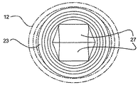
特に図1に見られるように、入口11に隣接する頂部12の頂面15は、二つのハイポイントA及び二つのローポイントBの間で遷移する。それぞれのハイポイントAは互いに約180°離間されており、それぞれのローポイントBも互いに約180°離間されており、それぞれのハイポイントAはそれぞれのローポイントBから約90°離間されている。好ましくは、それぞれのハイポイントAは、それぞれのローポイントBよりも、ゼロより大きく約0.050インチ(1.143ミリメートル)より小さい高さだけ高い。最も好ましくは、それぞれのハイポイントAは、それぞれのローポイントBよりも、約0.027インチ(0.686ミリメートル)だけ高くされるべきである。ハイポイントAとローポイントBとの間でスムーズにうねるように遷移する、スムーズな円周頂面15を達成するため、頂面15は、約0.30インチ(7.62ミリメートル)の半径を有する曲面を、近位部12の頂を切断するためのテンプレートとして用いることによって、形成され得る。幾何学的には、近位部12の頂によって区画される仮想シリンダC1は、約0.30インチ(7.62ミリメートル)の半径を有する仮想シリンダC2であって、近位部12の頂によって区画される仮想シリンダC1の長手軸に対し90°をなすよう方向付けられる仮想シリンダC2によって、切断され得る。これは、前記形状をもつ頂面15に帰結する。仮想シリンダC1の半径を変えることにより、ハイポイントA及びローポイントBの間の距離は変更されることができる。図1Aを参照のこと。当然、他の形状が採用されても良く、これは、ハイポイント及びローポイントが採用されてもよいこと、及びハイポイント及びローポイントが発明の実施の形態であることに、帰結する。
As can be seen in particular in FIG. 1, the
隔壁20が、ニードルレスルアーアクセスコネクタの頂部12に位置され、それを通る流体の流れを制御する。典型的に、シリコンやポリイソプレン等の材料が隔壁20を形成するため用いられることができる。隔壁20は、拡大された近位部21、中間部22、及び拡大された遠位部23を有する。拡大された近位部21の頂には、近位部21の周縁部に沿って伸長された環状リップ(又はへり)24が形成され得る。リップ24は、拡大された近位部21が雄ルアーテーパによってアクセスされたとき、拡大された近位部21が折れ曲がらぬような追加の剛性を、拡大された近位部21に与える追加の質量を提供する。中間部22は、近位部21の断面積より小さく且つ遠位部23の断面積より小さい断面積を有する。好ましくは中間部22は、入口11の内径に実質的に等しい主軸M1を有する略長円状の断面を有する。或いは、隔壁20が入口11に残るのを確実にするのを助長するため、主軸は入口11の内径より僅かに大きくても良い。中間部22の副軸M2は、近位部21の直径より小さく且つ入口11の内径より小さい。結局、中間部22は、入口11の断面積より小さい断面積を有する。これは、主軸に沿った中間部22の外表面と、入口11を区画するハウジング10の側壁との間に、雄ルアーテーパが隔壁20内に配置されたときに隔壁20の材料が変位し得るスペースを提供する。図7に見られるように、拡大された遠位部23は、その底部の周りに延在する環状溝26を区画する。また、拡大された直径部27が、拡大された遠位部23を横切って延在する。
A
スリット25が、隔壁20に形成されるとともに、近位部21、中間部22及び遠位部23を通過して縦に延在する。図5の隔壁20の平面図に見られるように、スリット25は、横断軸Tを有するとともに、一対の側部25a及び一対の端部25bによって区画される。好ましくは、拡大された遠位部23の直径部27は、頂点28に沿うスリット25の両側部25aから延び、拡大された遠位部23の底面に戻る。直径部27は、スリット25を流体流れに対し閉じ続けるのを助長するための、スリット25の底部に隣接する増加された質量を提供する。
A
隔壁20はハウジング10の頂部12内に配置され、これにより拡大された近位部21が頂面15の頂に着座するようになる。結果的に、拡大された近位部21は入口11の頂の上に突出する。加えて、頂面15のうねり形状のため、近位部21はハイポイントAに沿って押し上げられる。接着剤(溶接又は硬化された接着材料)が、近位部21をハウジング10の頂部12によりよく固定するために用いられても良い。隔壁20は、スリット25の両側部25aの中心がそれぞれのハイポントAに整列され、横断軸TがローポイントBに整列されるよう、ハウジング10内で整列される。それゆえ、中間部22の副軸はハイポイントAに整列され、中間部22の主軸はローポイントBに整列される。遠位部23は、好ましくは底部16の頂壁が隔壁20の環状溝26と係合するように、ハウジング10の頂部12と底部16との間に捕獲される。頂部12の底壁は、ルアーロックカラー16aに隣接して底部23の中間部に沿って形成される円周フランジ19に固着される。もし望まれれば、環状溝19aがフランジ19に形成されることができ、頂部12の底壁が環状溝19aに挿入されることができる。化学的接着剤や超音波溶接等のいかなる標準的固着技術も、頂部12を底部16に固着するのに用いられることができる。好ましくは、隔壁20がハウジング10内に位置されたとき、中間部22には張力がかけられる。頂面15のハイポイントAによって持ち上げられる近位部21の部分との組み合わせで、この張力は、両側部25aに作用されてスリット25を少なくとも近位部21の頂で強制閉鎖する圧縮力となる。
The
注射器などの他の医療機器の雄ルアーテーパが、隔壁20の近位部21の頂に押し付けられると、近位部21は、遠位方向且つ側方に変形し、雄ルアーテーパが隔壁20のスリット25にアクセスするのを許容する。雄ルアーテーパがさらにスリット25内に押し込まれると、中間部22もまた遠位方向且つ側方に変形する。図2と図3とを比較のこと。中間部22がボア13の断面より小さい断面を有することにより、ボア13の内側に、そのような中間部22の側方への変形を許容するスペースが提供される。この隔壁20の遠位方向且つ側方への変形は、スリット25を強制開放し、雄ルアーテーパがスリット25に入って隔壁20を貫通するのを許容する。雄ルアーテーパが隔壁20に完全に挿入されると、スリット25は、隔壁20の全長に沿って強制開放され、これにより、流体が、隔壁20及び本発明のニードルレスルアーアクセスコネクタを通過して流れることを許容する。この後、他の医療機器の雄ルアーテーパはスリット25から引き抜かれることができる。隔壁20の固有の弾性が、隔壁20を、スリット25が閉じられるその通常の応力がかけられていない状態に復帰させる。これは、隔壁20を通じるいかなるさらなる流体流れをも阻止する。空気通路197が、ボア13を環境に接続し、隔壁がボアの中で変形するときの空気の逃げを許容する。このように、ハウジング内の空気は圧縮される必要がない。さらに、雄ルアーテーパが取り除かれたとき、ボアの中には負圧がなく、このことは隔壁が密閉された状態に戻るのを防止するであろう。
When the male luer taper of another medical device, such as a syringe, is pressed against the apex of the
隔壁20がシリコンやポリイソプレン等の材料から形成されることができるので、雄ルアーテーパがハウジング10から引き抜かれるとき、隔壁20が雄ルアーテーパに固着されて隔壁20がハウジング10から引き抜かれる可能性がある。この潜在的問題を回避するため、ハウジングの頂部12に潤滑剤が与えられても良い。また、硬化接着材料や溶接等の接着剤150が、隔壁をハウジングに固着するのに使用されても良い。また、隔壁をハウジングにより良好に固着するため、ハウジング10の頂部12と隔壁20とには、隔壁20の近位部21を定位置に保持する相補的な捕獲要素が形成されても良い。例えば、頂部12の内面の円周周りに少なくとも部分的に沿って延在する溝50が、頂面15に近接して形成されることができる。このような実施形態において、二つの溝50が、頂部12の内面に、約180°離れて、ハイポイントAに整列されて位置されることができる。或いは、溝50は、頂部12の内面の全周周りに延在しても良い。図9から図11を参照のこと。リブ51が、中間部22の一部に沿って形成され、溝50に嵌まるよう用いられても良い。好ましくは、二つのリブ51が用いられ、これらリブ51が、中間部22の主軸に沿って、約180°離れて、中間部22の両側部に位置される。溝50は、頂部12の両側部に位置されてそれらリブ51と係合する。結局、雄ルアーテーパがスリット25に入ると、中間部22が変形され、雄ルアーテーパが隔壁20から取り除かれるまで、リブ51が溝50に嵌まり隔壁20をハウジング10内に保持する。この溝50とリブ51との内部係合は、雄ルアーテーパがハウジング10から引き抜かるとき隔壁20が雄ルアーテーパに固着し、隔壁20がハウジング10から引き抜かれるという潜在的問題を回避する。隔壁20が雄ルアーテーパにより側方且つ遠位方向に変形されたとき、溝50とリブ51とが互いに係合するので、隔壁20をハウジング10から引き抜くことなく、雄ルアーテーパは隔壁20から取り外されることができる。溝50とリブ51との縦(長手方向)の位置は、隔壁20の一部がどこで近位部12の内壁に係合するかを調べるという簡単な通常の実験によって決定され得る。雄ルアーテーパが隔壁20から取り除かれ、これによって隔壁10をその付勢されてない、即ち、応力がかけられていない状態に戻すとき、隔壁20の固有の弾性が、溝50とリブ51とを互いに分離させることを許容する。
Since the
この構成の変形例が図12及び図13に示され、これにおいて、少なくとも一つのリブ61が、頂部12に、入口11に隣接して且つ入口11の内方に延出して形成されている。好ましくは、二つのリブ61が用いられ、これらリブ61が、約180°離れて位置され、ハイポイントAに隣接される。或いは、一つのリブ61が用いられ、このリブ61が頂部12の内面の全周に沿って延在しても良い。こうしてリブ61は中間部22の主軸に面し、これにより、雄ルアーテーパがスリット25に入って隔壁20が側方及び遠位方向に変形されたとき、リブ61が隔壁20に係合して隔壁20をハウジング10内に保持する。その固有の弾性のため、隔壁20は、雄ルアーテーパが隔壁20から取り除かれるまで、リブ61の形状に倣い、リブ61に係合し、リブ61によって保持されることができる。
A variation of this configuration is shown in FIGS. 12 and 13 in which at least one
隔壁20の中間部22の外面には、主軸に沿う、約180°離れたリブ31が形成されても良い。また、相補的なかかり(barb)32が、ハウジング10の近位部12の内側壁に、入口11付近に、ハイポイントAと整列して、形成されても良い。図14から図16を参照のこと。リブ31とかかり32とは、互いに接触されるようになったとき、互いに係合するように形成されている。結局、他の医療機器の雄ルアーテーパが隔壁20に完全に挿入されたとき、隔壁20の中間部22の外面は遠位方向且つ側方に押しやられ、これにより、その外面はハウジング10の近位部12の内側壁と係合する。リブ31が隔壁20に位置されるとともにかかり32がハウジング10の頂部12の内側壁に位置されており、これにより、隔壁20が雄ルアーテーパにより完全にアクセスされたとき、リブ31がかかり32に係合する。好ましくは、二つのリブ31が、隔壁20に、約180°離れて、中間部22の両側に沿って、その主軸に沿って、形成される。好ましくは、二つのかかり32が、頂部12の内側壁に、約180°離れて、ハイポイントAに整列して、位置される。そしてこれらかかり32は、雄ルアーテーパが隔壁20に挿入されたとき、リブ31に隣接する。リブ31とかかり32との縦の位置は、隔壁20の一部がどこで近位部12の内壁に係合するかを調べるという簡単な通常の実験によって決定され得る。リブ31とかかり32との内部係合は、雄ルアーテーパがスリット25から引き抜かれているとき、隔壁20をハウジング10に対して定位置に維持するのを助ける。この内部係合は、雄ルアーテーパがハウジング10から引き抜かれるとき隔壁20が雄ルアーテーパに固着し、隔壁20がハウジング10から引き抜かれるという潜在的問題を回避する。リブ31とかかり32とが互いに干渉し合い且つ係合するので、ハウジング10から隔壁20を引き出すこと無く、雄ルアーテーパは隔壁20から取り外され得る。しかしながら、雄ルアーテーパが隔壁20から取り除かれ、これによって隔壁10がその付勢されてない状態に戻ることを許容するとき、隔壁20の固有の弾性が、リブ31とかかり32とを互いに分離させることを許容する。
On the outer surface of the
この効果を達成するためにリブ31とかかり32との様々な形態が使用され得る。例えば、補完的なリブとデテント(移動止め;detent)又は溝とが、隔壁20の中間部22の外面と、頂部12の内側壁とに形成され得る。かかり32は、頂部12の軸長に沿ったいずれの位置にも形成されることができるが、好ましくはかかり32は、頂面15付近に、入口11に隣接して位置される。これは、隔壁20のより小さな部分をかかり32の上に残す(その小さな部分は、雄ルアーテーパが隔壁20から取り除かれるとき、頂部12から引き抜かれるかもしれない)。もしかかり32が頂面15から遠位方向にあまりに遠くに位置されていると、隔壁20の多くの部分が引き伸ばされ、頂部12から引き出されるかもしれない(もし隔壁20のその部分が雄ルアーテーパに固着していたならば)。
Various forms of
前記特徴の変形例は、隔壁20と頂部12とに形成された様々なキーとキー穴との使用である。これらは、雄ルアーテーパの隔壁20への挿入、又は雄ルアーテーパの隔壁20からの取り出しの最中に、隔壁20の回転を防止する。図17〜図28を参照のこと。これは、特に入口11が雄ルアーロック用に形成されている場合に必要かもしれない。この場合、雄ルアーテーパをコネクタに挿入してそれを定位置にロックするため、及び雄ルアーテーパをロック解除してそれをコネクタから取り外すため、他の医療機器の雄ルアーテーパは、本発明のニードルレスルアーアクセスコネクタのハウジング10に対して、典型的に回転される。例えば、キー40が隔壁20に形成されることができ、キー40は、隔壁20の拡大された近位部21に隣接され、中間部22の副軸に沿って、スリット25の横断軸T及び中間部22の主軸に整列されて(すなわち、同一直線状に又は平行に)、形成されることができる。キー40は、単に隔壁20の一側からの延出物であることができ、あらゆる形状に形成されることができる。例えば、単純な四角形(図17及び図18参照)が用いられることができ、同様に、三角形(図19〜図22参照)又は他の多角形(図23及び図24参照)が用いられることができる。好ましくは、二つのキー40が用いられ、これらキー40は、約180°離れて位置され、横断軸T及び中間部22の主軸に整列される。補完的な溝又はキー穴41が、ハウジング10の頂部12における頂面に沿ってかつそれに隣接して形成されることができる。好ましくは、二つのキー穴41が用いられ、これらキー穴41は、約180°離れて位置され、ローポイントBに整列される。キー40は、拡大された近位部21の外周縁にまで延在する必要はなく、キー穴41は、頂部12の側壁を完全に貫通する必要はない。或いは、キー40は、中間部22から延出するリブとして形成されることもできるし、キー穴41は、頂部12の内側壁に形成された補完的な溝として形成されることもできる。唯一の限定は、キー40とキー穴41とが、お互いに対して形状付けられ且つ配置されなければならないことである。これにより、これらは組み合って、隔壁20を、ハウジング10に対する回転動作に逆らって保持する。さらに、キー40aが、ハウジング10の頂部12の頂面15に沿って形成されることができ、キー穴41aが、近位部21に隣接して隔壁20に形成されることができる。図25〜図28を参照のこと。好ましくは、二つのキー40a及び二つのキー穴41aが用いられ、その二つのキー40aは約180°離れて位置され、その二つのキー穴41aは約180°離れて位置される。キー40a及びキー穴41aは、近位部21の周方向に沿ったいかなる位置にも配置されることができる。しかしながら、好ましくは、キー40aがローポイントBに整列され、キー穴41aが、中間部22の主軸及びスリット25の横断軸Tに整列される。図17〜図28の実施形態は、好ましくは、ハイポイントA及びローポイントBを持つ頂面15を有するが、これら実施形態のキー及びキー穴は、本発明のニードルレスルアーアクセスコネクタがハイポイント及びローポイントの無いフラットな頂面15を有する場合に、用いられることができる。
A variation of the above feature is the use of various keys and key holes formed in the
ボア13には、縦に延在する溝71が形成されることができる。この溝71は中間部22の端部に係合する。図29及び図30を参照のこと。好ましくは、二つの溝71が用いられ、それぞれの溝71は、好ましくは、約180°離れて位置され、ローポイントBに実質的に整列される。この方法において、副軸に平行な中間部22のそれぞれの端は、溝71に係合して、隔壁20を、ボア13に対する回転に逆らって保持する。これに代わって、ボア13には、二つのショルダー(肩部)72が形成されることができる。ショルダー72は中間部22の端部に係合する。図31及び図32を参照のこと。再度好ましくは、二つのショルダー72が用いられ、それぞれのショルダー72は、好ましくは、約180°離れて位置され、ローポイントBに実質的に整列される。これらのボア13に対する構成は、雄ルアーテーパがこれをねじることにより隔壁20に挿入され又は隔壁から取り外される場合に、ハウジング10に対する回転に抗して中間部22ひいては隔壁20を定位置に保持するのを助ける。
The
隔壁20の近位部21が、ハウジング10の頂部12の頂面15に単に着座しているだけなので、雄ルアーテーパが近位部21の頂に押し付けられたとき、近位部21が、頂部12のボア13内に押し込まれる可能性がある。雄ルアーテーパがスリット25内に押し込まれたとき、近位部21を定位置に保持するのを助けるための隔壁20とハウジング10との構成が、図33〜図36に示される。この実施形態においては、立上り部(riser)81が、頂面15に隣接して且つ頂面15から立ち上がって頂部12に形成されるとともに、約180°離れて位置される。立上り部81は、外側に延出するフランジ82を含む。スロット部83が、近位部21の周縁部に沿って形成されるとともに、フランジ82がスロット部83内に入り且つこれを通過するのを許容する。好ましくは、約180°離れた二つのスロット部83が、近位部21に形成されるとともに、スリット25の両側でスリット25の横断軸Tに略平行に延在する。もし望まれれば、スロット部83に係合するためのかかりが、立上り部81又はフランジ82に形成されて、スロット部83を頂面15に対し定位置に保持するのを助けることができる。この係合も、雄ルアーテーパがスリット25内に押し込まれたとき、近位部21を定位置に保持するのを助ける。好ましくは、本実施形態において頂面15は平坦である。しかしながら、もし望まれれば、頂面15は、他の実施形態のように、ハイポイントとローポイントとを有したうねった曲面によって形成されても良い。このようなうねった曲面が使用される場合、立上り部81はハイポイントを含むであろう。
Since the
流体流れに対するスリット25の閉止を容易にするため、隔壁20の遠位部23に係合するハウジング10の部分は、ハウジング10がスリット25の両側に沿って隔壁20の遠位部23を圧縮するように、形成されることができる。これに代わって又はこれと共に、隔壁20の遠位部23に係合するハウジング10の部分は、ハウジング10が隔壁20の遠位部23を、スリット25の両端で、即ち、横断軸Tに沿って、引っ張るように、形成されることができる。この力の分配を行うための一つの方法は、隔壁20の遠位部23を、実質的に円形の断面に形成し、遠位部23に係合するハウジング10の部分を、実質的に長円形又は楕円形の断面に形成することである。図38を参照のこと。横断軸Tが楕円の主軸に平行になるようにスリット25を位置づけることで、スリット25は閉止位置に付勢されるであろう。なぜなら、楕円の副軸がスリット25の両側部25aを互いに圧縮しようとし、同時に、楕円の主軸がスリット25の両端部25bを引っ張ってスリット25を強制閉止しようとするからである。ここに述べられたように、スリット25に沿う張力及びスリット25に垂直な圧縮力のいずれも作用されることができるが、必ずしも両者が作用されなくても良い。楕円の副軸を、遠位部23の円形断面の直径と実質的に等しくなるように形成し、楕円の主軸を、その直径より大きくなるように形成することによって、張力のみが働き得る。楕円の副軸を、その直径より小さくなるように形成し、楕円の主軸を、その直径と実質的に等しくなるように形成することによって、圧縮力のみが働き得る。隔壁20の遠位部23と、遠位部23に係合するハウジング10の部分とに相補的なタブ及び溝を形成し、遠位部23を上述のように適当な方向に押し引きすることによって、この効果が達成され得る。
To facilitate closing of the
これに代わり、そして好ましくは、隔壁20の遠位部23は楕円形に形成され、遠位部23に係合するハウジング10の部分は断面円形に形成される。図37を参照のこと。遠位部23が楕円形に形成されるとき、スリット25の横断軸Tは好ましくは楕円の副軸に整列、即ち、同一直線状とされる。遠位部23と、遠位部23に係合するハウジング10の部分とに対するこの構成は本発明のニードルレスアクセスコネクタの製造を容易にする。なぜなら遠位部23及びハウジング10の間の特別な整列を要求しないからである。楕円の副軸を、遠位部23の円形断面の直径より小さくなるように形成し、楕円の主軸を、その直径と実質的に等しくなるように形成することによって、張力のみが働き得る。楕円の副軸を、その直径と実質的に等しくなるように形成し、楕円の主軸を、その直径より大きくなるように形成することによって、圧縮力のみが働き得る。好ましくは、この構成において、遠位部23がその応力がかけられていない状態にあるとき、遠位部23の副軸は約0.360インチ(9.144ミリメートル)であり、遠位部23の主軸は約0.430インチ(10.922ミリメートル)である。もし望まれれば、スリット25は、遠位部23がその応力がかけられていない状態にあるとき開かれるように、形成されることができる。この状況で、スリット25は、遠位部23において、約0.030インチ(0.762ミリメートル)の副軸と約0.175インチ(4.445ミリメートル)の主軸とを有する楕円断面を有し、遠位部23は、約0.360インチ(9.144ミリメートル)の副軸と約0.460インチ(11.684ミリメートル)の主軸とを有する。図40を参照のこと。当然、隔壁20には、遠位部23における円形断面と開放スリット25とが形成されることができる。図42を参照のこと。あるいは、隔壁20には、遠位部23における楕円形断面と閉止スリット25とが形成されることができ(図39参照)、もしくは遠位部23における円形断面と閉止スリット25とが形成されることができる(図41参照)。
Alternatively and preferably, the
雄ルアーテーパが隔壁20の頂部近位面に抗して押されると、近位部21は遠位方向且つ側方に変形し、雄ルアーテーパが隔壁20のスリット25にアクセスするのを許容する。雄ルアーテーパがさらにスリット25内に押し込まれるにつれ、中間部22も遠位方向且つ側方に変形する。中間部22がボア13の断面より小さい断面を有することにより、ハウジング10の内側に、そのような中間部22の側方への変形を許容するスペースが提供される。この隔壁20の遠位方向且つ側方への変形は、スリット25を強制開放し、雄ルアーテーパがスリット25に入って隔壁20を貫通するのを許容する。雄ルアーテーパが隔壁20に完全に挿入されると、スリット25は、隔壁20の全長に沿って強制開放される。
When the male luer taper is pushed against the top proximal surface of the
特定のISO規格のため、たとえ雄ルアーテーパが隔壁20を完全に貫通しなくても、スリット25が隔壁20の全長に亘って開放されていることが重要である。雄ルアーテーパに対し、ISO規格594−2:1998(E)は、雄ルアーテーパが、約0.295インチ(7.5ミリメートル)の最小長さを有し、ルアーロックカラーの端を超えて最低0.083インチ(2.1ミリメートル)延出することを要求する。多くのメーカーは製品をこの最小寸法としている。本発明のニードルレスアクセスコネクタにおいて、近位部12の中間側壁の頂と隔壁20の底との間の距離Xは約0.110インチ(2.794ミリメートル)である。結局、本発明のニードルレスアクセスコネクタにアクセスするために、最小のISO寸法を有する雄ルアーテーパが用いられる場合、雄ルアーテーパが隔壁20を完全に貫通しないことが見られる。これらの寸法のため、隔壁20は、たとえ雄ルアーテーパが隔壁20を完全に貫通しなくてもスリット25が強制開放されるように、設計されなければならない。雄ルアーテーパが、隔壁20の頂から0.214インチ(5.436ミリメートル)の距離だけ隔壁20に挿入されるとき、スリット25の底が開き始める。雄ルアーテーパが、ニードルレスアクセスコネクタ内にできるだけ延在できるよう挿入されるとき、遠位部23は、雄ルアーテーパによってアクセスされないとき遠位部23の底が広がる位置より下で、ボア13内に遠位方向且つ下方に変形され得るだけである。この遠位変形は、遠位部23を、揺動ドア及び完全開放スリット25として機能させる。遠位部23の遠位変形のみが存在する。なぜなら遠位部23の周縁部が、ハウジング10の近位部12と遠位部16との間の定位置に保持され、遠位部23が遠位方向以外に動く余地が無いからである。また、遠位部23は、その厚さに起因する増加された質量を有している。その厚さは約0.050インチ(1.27ミリメートル)であり、スリット25の直近で隣接する約0.080インチ(2.032ミリメートル)までテーパになる。この、遠位部23を側方移動に抗して保持することと、遠位部の増加された質量との組み合わせは、スリット25を強制開放すると共に、雄ルアーテーパが隔壁20を完全に貫通しなくても流体がニードルレスルアーアクセスコネクタを通過するのを許容する。
Due to the specific ISO standard, it is important that the
ハウジング10は、流体が流れて溜まり得るその中のデッドスペースの大きさを最小にするように設計される。そのような溜まった流体は、ニードルレスルアーアクセスコネクタを介して患者に入り患者を感染させる虞のある細菌や他の有機体のための繁殖場所を提供する可能性がある。好ましくは、壁60がハウジング10の遠位部16に形成されて内部のデッドスペースを埋める。壁60は上向きの面61を有し、この面61は、雄ルアーテーパが本発明のニードルレスルアーアクセスコネクタに完全にアクセスしたとき、隔壁20の遠位部23の形状に適合する。図48を参照のこと。この方法で、壁60は、本発明の通常の作動を妨げず、ハウジング10内の使用されないスペースを満たす。
The
このように、ニードルの使用なしにアクセスされることができ、漏れ及び細菌の進入がありがちでなく、内部のデッドスペース容積を最小にし、アクセスに高い程度の力を必要とせず、コネクタがアクセスされるときの反動力を最少にし、アクセスに追加の又は特別な装置を必要としない、ニードルレスアクセスコネクタが提供されることが理解される。 In this way, it can be accessed without the use of a needle, it is prone to leaks and bacterial ingress, minimizes internal dead space volume, does not require a high degree of access, and connectors are accessed. It will be appreciated that a needleless access connector is provided that minimizes reaction force and does not require additional or special equipment for access.
上述のニードルレスルアーコネクタは、コネクタの予定される用途に応じた固有の性能特性を発揮するように変形されても良い。特に、本発明のある実施形態において、隔壁に圧縮力を作用してスリットを閉止位置に付勢するようにハウジングを設計することが望ましい場合がある。ハウジングと隔壁との間に機械的固着が形成されても良い。この固着は、挿入中に雄ルアーテーパによって作用される力の下で隔壁を定位置に維持し、雄ルアーテーパがスリット内に無いときにスリットを閉止位置に維持する。これらの変形が、他のコネクタに採用されることができると共に本発明の実施形態であることが認識されるであろう。 The needleless luer connector described above may be modified to exhibit unique performance characteristics depending on the intended use of the connector. In particular, in certain embodiments of the present invention, it may be desirable to design the housing to apply a compressive force to the septum to bias the slit to the closed position. A mechanical bond may be formed between the housing and the partition. This anchoring maintains the septum in place under the force exerted by the male luer taper during insertion and maintains the slit in the closed position when the male luer taper is not in the slit. It will be appreciated that these variations can be employed with other connectors and are embodiments of the present invention.
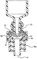
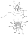
ここで図49〜図64を参照して、ニードルレスルアーアクセスコネクタ100は実質的に円形のベース110を含んでもよい。ベース110は、近位方向から遠位方向に伸びる軸112を有する。弾性部材、例えばリーフスプリング111が、ベースに取り付けられると共に近位方向に伸長し、これによって流路113を区画する。隔壁ないしバルブ130は、近位部131、中間部132、及び遠位部133を有する。近位部と遠位部とは、好ましくは、応力が加えられていないときにおいて円形断面を有する(例えば図49に示される如き)。中間部は、好ましくは、応力が加えられていないときにおいて楕円形断面を有する(例えば図49及び図55に示される如き)。中間部の楕円形断面は主軸M1と副軸M2とを有する(図55参照)。縦のスリット136は、雄ルアーテーパがスリット内に挿入されたとき中間部が膨張するように、近位部から中間部を通って遠位部へと隔壁を通じて延在する。図54及び図56を参照のこと。
49-64, the needleless
使用のため組み立てられるとき、隔壁130の遠位部133はハウジング115のベース110内に位置される。隔壁の中間部132は流路113内に位置される。潤滑剤が隔壁の中間部に沿って位置されても良い。隔壁131の近位部は、ベースから離れてリーフスプリング111の上に着座される。特に、近位部はリーフスプリングの頂端縁120の上に配置される。リーフスプリングは、隔壁が軸方向に張力をかけられるようなサイズとされる。この張力は、スリット136から離れたハウジングの位置付けと組み合わさって、スリットを閉止状態に付勢する。また、特定の一実施形態において、少なくとも一つのリーフスプリングが、隔壁の中間部に、その主軸M1に沿って作動可能に係合され、少なくとも一つのリーフスプリングが、隔壁の中間部に、その副軸M2に沿って作動可能に係合される。好ましくは、二つのリーフスプリングが、ベースに取り付けられると共に、ルアーコネクタに係合するためのネジを含む。これらリーフスプリングは、隔壁の中間部に、その主軸に沿って係合される(図52参照)。二つの他のリーフスプリングが、ベースに取り付けられると共に、ベースの軸に対して内側に傾斜されている。これらリーフスプリングは、隔壁の中間部に、その副軸に沿って、隔壁の近位部付近で接触する(図53参照)。リブ137が、中間部の外面138と近位部の底面139とに位置されてもよく、これによってリーフスプリングがリブに接触する。好ましくは、リブは隔壁に一体的に形成される。雄ルアーコネクタがコネクタに挿入されると、中間部とリブとは外側に変形され、副軸M2に沿ったリーフスプリングの付勢に打ち勝つ(図54参照)。
When assembled for use, the
図52〜図54を参照して、雄ルアーチップがスリット136に挿入される前に、リーフスプリング111は、リブ137を介して、隔壁130の中間部132に力を作用し、スリットを閉止状態に付勢する。雄ルアーテーパがスリットに挿入されるにつれ、隔壁は膨らんでテーパを受け入れる。隔壁の中間部は、リーフスプリングに抗して膨らみ、それを外側に曲げる。隔壁とハウジングとの間の接着剤が、雄ルアーテーパの挿入中に隔壁がハウジング内に押されるのを回避するのを助ける。
52 to 54, before the male luer tip is inserted into the
本発明のこの形態のある実施例において、リップ114が、少なくとも一つのリーフスプリング111の近位端に取り付けられ、これによってリップが、隔壁130の近位部131の少なくとも一部を取り囲むようになる。接着材料150が、隔壁とリーフスプリングとの間に配置され、隔壁をリーフスプリングに固定しても良い。
In certain embodiments of this aspect of the invention, a
図57〜図60を参照して、ニードルレスアクセスコネクタ100はハウジング115を含み、ハウジング115は、近位面124を含むベース部110と、ベース部上に位置された側壁125とを有する。側壁はベース部と一体に形成されてもよい。また、側壁は、リーフスプリング又は他の弾性部材111から形成されても良い。側壁は頂部120を含み、頂部120は、周縁部を有すると共に、入口開口121を区画する。ハウジングの頂部は、直径方向反対側に位置された二つのハイポイントAと、直径方向反対側に位置された二つのローポイントBとを含み、直径方向反対側に位置されたローポイントは、スリット136の横断軸Tに沿って配置される(図1、図1A、図4及び図5も参照のこと)。側壁は、流体流れが流通可能に入口開口121と連通する流路113を区画する。隔壁130はハウジング内に配置される。隔壁の中間部132は、近位部の断面より小さい断面を有する。また、中間部の断面は、流路の断面より小さい。縦のスリット136は、横断軸Tを有すると共に(図5参照)、近位部131から中間部132を通って遠位部133まで延在する。これにより、雄ルアーテーパ200がスリットに挿入されたとき、遠位部が側方及び遠位方向に移動して流れの通路を開放し、流路に連通させる。リップ114がハウジング115の頂部120の外周縁に取り付けられ、これにより、リップは隔壁130の近位部131の少なくとも一部を取り囲む。空気穴197が、隔壁の中間部とハウジングとの間の空気密閉状態を回避すべく、ハウジングに含まれていても良い。このような空気密閉状態は、雄ルアーチップの完全挿入を妨げるかもしれないし、または、チップの取り外しに際し、隔壁が密閉状態に戻るのを妨げるかもしれない。
Referring to FIGS. 57-60,
好ましくは、リップ114は、ハウジング115に一体に形成されると共に、ハウジングの頂部120の外周縁に沿って隣接して(つながって)伸長し、これにより隔壁130の近位部131を完全に取り囲む。当然、リップには、隔壁の近位部に選択された位置で係合する独立タブ116が形成されても良い(図59参照)。好ましくは、リップは、それが隔壁の近位部に圧縮力を作用し、近位部を密閉状態に向けて付勢するようなサイズとされる。特に、リップが、スリット136の横断軸Tに垂直な方向に圧縮力を作用するのが好ましい。
Preferably, the
隔壁130の近位部131は、厚さT2を有する周縁リム141を備える。リップの高さHは、それが周縁リムの厚さより小さく、且つ隔壁の近位端の頂面142がリップの上方に突出するように、選択されることができる。或いは、リップの高さは、それがリムの厚さより大きく、隔壁の面がリップより凹まされるように、選択されることができる。また、リップは、リムと同じ高さを有するようなサイズとされることもできる。使用時に隔壁をより良好に定位置に固定するため、接着材料150が、隔壁の近位部と側壁の頂部120との間に配置されてもよい。
The
本発明の一形態によれば、隔壁のリムをハウジングに機械的に固定するためリップ114が採用され得る。特にリップは、例えば冷間成形、加熱、又は超音波により、丸められてリムを覆っても良い。この場合、リップ(丸められる前)は好ましくはリムより高い。それは丸められて、リムを、リップとハウジングとの間に挟む。
According to one aspect of the invention, a
本発明の他の形態によれば、ブラントカニューレ(blunt cannula)による患者への選択的な流体の注入を許容するための方法が提供される。ハウジング115はベース110を有し、ベース110は頂面120を有し、頂面120は入口開口121を区画する。少なくとも一つの側壁125がベース部110から延在して流路113を区画する。ベース部は、出口開口126を有し、これにより入口開口と出口開口とが流体流通可能に連通される。隔壁130はハウジングに挿入される。隔壁の近位部131は、ハウジングの頂面120の位置に配置された遠位面139を有する。隔壁の中間部132は、少なくとも部分的に、ハウジングの流路内に配置される。隔壁は、少なくともその近位部を通過するスリット136を区画する。接着剤150が、ハウジングと隔壁とに塗布され、隔壁は圧縮状態に変形されてスリットを閉止位置に付勢する。この圧縮状態は、隔壁を圧縮するアクチュエータを用いることにより、又はハウジングを隔壁の近位部に圧縮力を作用するように形成することにより、達成され得る。現在好ましいように、本発明の一形態によれば、圧縮力は、前記図1Aに関連して説明されたハウジングの頂面の鞍形により達成される。一旦隔壁が圧縮状態にされると、接着剤が硬化され、これにより、隔壁が、硬化された接着剤とハウジングとの協働作用により、圧縮状態に維持される。
In accordance with another aspect of the present invention, a method is provided for allowing selective fluid injection into a patient via a blunt cannula. The
接着材料150が、隔壁を定位置に維持するため様々な方法で塗布され得る。本発明の一形態によれば、接着剤150は、隔壁130の近位部131とハウジング115の頂部120とによって形成された溝122の位置に塗布される。ハウジング115又はリーフスプリング111の頂端縁120の間の位置に接着材料を供給するため、機械フィンガー(mechanical fingers)等のアクチュエータが、隔壁130のリム141のエッジを丸め上げるために用いられ得る。その後、隙間123が隔壁とハウジングとの間に形成され、そこに、液体接着材料が、例えばスプレーすることにより、塗布され得る。また、接着剤が塗布された後、接着剤の硬化中隔壁を圧縮状態に維持するため、アクチュエータが用いられてもよい。ある用途において、接着剤は、紫外線光の使用により硬化可能であってもよい。この場合、ハウジングの少なくとも頂部12が、光を通過可能な材料から形成される。紫外線光は、紫外線光源160によって供給されると共に、ハウジングの頂部を通過して接着剤に供給され、これにより接着材料を硬化させる。
The
本発明のある形態が、他の隔壁・ハウジング装置に用いられ得ることが認識されるであろう。例えば、図61に見られるように、隔壁330は弾性チューブ332から形成されても良い。弾性チューブ332は、隔壁の遠位端333に配置された開口340を有する。プラグ341が、雄ルアーテーパが挿入される前のチューブの遠位端を密閉する。接着材料350が、隔壁の近位端331をハウジングの定位置に固定する。スリット336が、隔壁の近位端を通じて延在すると共に、雄ルアーテーパが挿入されるまで密閉状態に維持される。参照により本願に組み込まれる米国特許5,242,393号明細書に述べられているように、雄ルアーチップがスリットに挿入されたとき、弾性チューブは変形されて、チューブを通り、開口を通り、またハウジングを通る流体流れ通路を作る。接着材料は、雄ルアーチップの挿入中、隔壁の近位部をハウジングの定位置に維持するのを助ける。
It will be appreciated that certain aspects of the present invention may be used with other bulkhead and housing devices. For example, as shown in FIG. 61, the
好適実施形態が図面に示され、これにおいて同様の符号は同様の要素を意味する。
Claims (48)
該ベースに取り付けられ、前記近位方向に伸び、これによって断面を有する流路を区画する複数のリーフスプリングと、
近位部、中間部及び遠位部を有する隔壁であって、前記近位部及び前記遠位部が応力を受けていないとき円形の断面を有し、前記中間部が応力を受けていないとき楕円形の断面を有し、該楕円形の断面が主軸と副軸とを有する隔壁と
を含み、
前記隔壁の前記遠位部が前記ベース内に配置され、前記隔壁の前記中間部が前記流路内に配置され、前記近位部が前記ベースから離れて前記リーフスプリングの上に着座され、
少なくとも一つの第1のリーフスプリングが、前記中間部の前記主軸に沿って前記隔壁の前記中間部に作動可能に係合され、
少なくとも一つの第2のリーフスプリングが、前記中間部の前記副軸に沿って前記隔壁の前記中間部に作動可能に係合され、
さらに、
前記近位部から前記中間部を通って前記遠位部まで前記隔壁を通じて延在する縦のスリットを含み、雄ルアーテーパが前記スリットに挿入されたとき前記中間部が膨張させられる
ニードルレスルアーアクセスコネクタ。 A substantially circular base having an axis extending from the proximal direction to the distal direction;
A plurality of leaf springs attached to the base and extending in the proximal direction thereby defining a flow path having a cross-section;
A septum having a proximal portion, an intermediate portion and a distal portion, having a circular cross section when the proximal portion and the distal portion are unstressed, and when the intermediate portion is unstressed A partition wall having an elliptical cross section, the elliptical cross section having a major axis and a minor axis;
The distal portion of the septum is disposed in the base, the intermediate portion of the septum is disposed in the flow path, and the proximal portion is seated on the leaf spring away from the base;
At least one first leaf spring is operably engaged with the intermediate portion of the partition along the main axis of the intermediate portion;
At least one second leaf spring is operably engaged with the intermediate portion of the septum along the secondary axis of the intermediate portion;
further,
A needleless luer access connector including a longitudinal slit extending through the septum from the proximal portion through the intermediate portion to the distal portion, wherein the intermediate portion is inflated when a male luer taper is inserted into the slit .
請求項1記載のニードルレスルアーアクセスコネクタ。 The needleless luer access connector of claim 1, further comprising a lip attached to at least one proximal end of the leaf spring, the lip surrounding at least a portion of the proximal portion of the septum.
請求項1記載のニードルレスルアーアクセスコネクタ。 The needleless luer access connector according to claim 1, further comprising an adhesive material disposed between the partition wall and the leaf spring to fix the partition wall to the leaf spring.
請求項1記載のニードルレスルアーアクセスコネクタ。 Two leaf springs are operatively engaged with the intermediate portion of the partition wall along the minor axis of the elliptical cross section, and the intermediate portion is expanded when a male luer taper is inserted into the slit. The needleless luer access connector according to claim 1, wherein the leaf spring is deformed outward.
請求項1記載のニードルレスルアーアクセスコネクタ。 The needleless lure according to claim 1, wherein the second leaf spring extends from the base in the proximal direction, is inclined toward the axis, and contacts the septum only at a proximal end of the second leaf spring. Access connector.
請求項1記載のニードルレスルアーアクセスコネクタ。 The needleless luer access connector according to claim 1, wherein the intermediate portion of the partition includes a rib extending substantially radially along the sub-axis and contacting at least one leaf spring.
前記隔壁と前記リーフスプリングとの間に配置されて前記隔壁を前記リーフスプリングに固定する接着材料と、
前記断面の前記主軸に沿って前記隔壁の前記中間部のそれぞれ反対側に位置される両側部に作動可能に係合される二つの第1のリーフスプリングと、
前記近位方向に伸び、前記軸に向けて傾斜され、前記楕円形断面の前記副軸に沿う前記隔壁の前記中間部のそれぞれ反対側に位置される両側部に作動可能に係合される二つの第2のリーフスプリングと
をさらに含み、
雄ルアーテーパが前記スリットに挿入されたとき、前記中間部が膨張させられて前記リーフスプリングを外側に変形させる
請求項1記載のニードルレスルアーアクセスコネクタ。 A lip attached to the proximal end of the leaf spring and surrounding at least a portion of the proximal end of the septum;
An adhesive material disposed between the partition wall and the leaf spring to fix the partition wall to the leaf spring;
Two first leaf springs operably engaged on opposite sides of the partition along the main axis of the cross section on opposite sides of the intermediate portion;
Two extending in the proximal direction, inclined toward the axis and operatively engaged with opposite sides of the intermediate portion of the partition wall along the minor axis of the elliptical cross section; Two second leaf springs,
The needleless luer access connector according to claim 1, wherein when a male luer taper is inserted into the slit, the intermediate portion is expanded to deform the leaf spring outward.
ベースを有するハウジングと、
前記ベースに取り付けられ、断面を有する流路を区画する複数のリーフスプリングと、
近位部及び中間部を有する隔壁であって、前記隔壁の前記中間部が前記流路内に配置され、前記近位部が前記ベースから離れて前記リーフスプリングの上に着座される隔壁と、
前記近位部から前記中間部まで前記隔壁を通じて延在する縦のスリットとを含み、
雄ルアーテーパが前記スリットに挿入されたとき、前記隔壁が前記ハウジングを通過する流体流れを阻止する閉止状態から、前記流体が前記隔壁を通過して流れ得る開放位置へと、前記スリットが動かされ、
前記リーフスプリングが前記隔壁に作動可能に係合され、前記隔壁を閉止状態に付勢する
コネクタ。 A connector for use with a male luer taper,
A housing having a base;
A plurality of leaf springs attached to the base and defining a flow path having a cross section;
A partition having a proximal portion and an intermediate portion, wherein the intermediate portion of the partition wall is disposed in the flow path, and the proximal portion is separated from the base and is seated on the leaf spring;
A vertical slit extending through the septum from the proximal portion to the intermediate portion,
When a male luer taper is inserted into the slit, the slit is moved from a closed state where the partition blocks fluid flow through the housing to an open position where the fluid can flow through the partition;
A connector, wherein the leaf spring is operatively engaged with the partition wall and biases the partition wall into a closed state.
請求項8記載のコネクタ。 The connector according to claim 8, wherein at least one rib that engages with at least one of the leaf springs is attached to the intermediate portion of the partition wall.
請求項9記載のコネクタ。 The connector according to claim 9, wherein the intermediate portion of the partition wall has an outer surface, and the rib is connected to the outer surface of the intermediate portion and a bottom surface of a proximal portion of the partition wall.
請求項9記載のコネクタ。 The connector according to claim 9, wherein the rib is formed integrally with the partition wall.
請求項9記載のコネクタ。 The connector according to claim 9, further comprising an adhesive material disposed between the partition wall and the leaf spring to fix the partition wall to the leaf spring.
請求項12記載のコネクタ。 The lip disposed in a proximal portion of the leaf spring, enclosing at least a portion of the proximal portion of the septum and biasing the proximal portion of the septum toward a closed state. connector.
該ハウジングに配置された隔壁であって、近位部、中間部及び遠位部を有し、前記中間部が、外面と、前記近位部の断面及び前記流路の断面より小さい断面とを有する隔壁と、
横断軸を有し、前記近位部から前記中間部を通って前記遠位部まで前記隔壁を通じて延在する縦のスリットであって、雄ルアーテーパが前記スリットに挿入されたとき、前記遠位部が側方及び遠位方向に動かされ、前記流路を通ずる流れ通路を開放するスリットと、
前記ハウジングの前記頂部の前記周縁部に取り付けられ、前記隔壁の前記近位部の少なくとも一部を取り囲むリップと
を含むニードルレスアクセスコネクタ。 A housing having a base portion having a proximal surface and a side wall located on the base portion, the side wall including a top portion having a peripheral edge and defining an inlet opening, wherein the side wall has a cross-section. A housing that divides the flow path, and the inlet opening and the flow path are in fluid communication with each other;
A septum disposed in the housing, having a proximal portion, an intermediate portion, and a distal portion, wherein the intermediate portion has an outer surface and a cross section smaller than a cross section of the proximal portion and a cross section of the flow path. A partition having,
A longitudinal slit having a transverse axis and extending through the septum from the proximal portion through the intermediate portion to the distal portion when the male luer taper is inserted into the slit. A slit that is moved laterally and distally to open a flow passage through the channel;
A needleless access connector including: a lip attached to the peripheral edge of the top of the housing and surrounding at least a portion of the proximal portion of the septum.
請求項14記載のニードルレスアクセスコネクタ。 The needleless access connector of claim 14, wherein the lip extends continuously along the peripheral edge of the top.
請求項14記載のニードルレスアクセスコネクタ。 The needleless access according to claim 14, wherein the proximal portion of the septum has a peripheral rim with a thickness, the lip has a height, and the height of the lip is less than the thickness of the peripheral rim. connector.
請求項14記載のニードルレスアクセスコネクタ。 15. The proximal portion of the septum has a peripheral rim having a thickness, the lip has a height, and the height of the lip is equal to or greater than the thickness of the peripheral rim. Needleless access connector.
請求項14記載のニードルレスアクセスコネクタ。 The needleless access connector according to claim 14, wherein the lip is integrally formed on the top of the housing.
請求項14記載のニードルレスアクセスコネクタ。 The needleless access connector of claim 14, wherein the lip comprises a plurality of independent tabs.
請求項14記載のニードルレスアクセスコネクタ。 The needleless access according to claim 14, further comprising an adhesive disposed between the proximal portion of the septum and the top of the sidewall, wherein the lip acts a compressive force on the proximal portion of the septum. connector.
請求項14記載のニードルレスアクセスコネクタ。 The needleless access connector according to claim 14, wherein the lip exerts a compressive force in a direction perpendicular to the transverse axis of the slit.
請求項14記載のニードルレスアクセスコネクタ。 15. The needleless access connector of claim 14, wherein the top portion of the housing includes two high points positioned diametrically opposite and two low points positioned diametrically opposite.
請求項14記載のニードルレスアクセスコネクタ。 The needleless access connector according to claim 14, wherein a low point located on the diametrically opposite side is disposed along the transverse axis of the slit.
請求項14記載のニードルレスアクセスコネクタ。 The needleless access connector according to claim 14, wherein the side wall of the housing is formed by a plurality of leaf springs attached to the base portion.
該ハウジングに配置されたバルブであって、近位部、中間部及び遠位部を有し、前記中間部が外面を有すると共に前記流路内に少なくとも部分的に配置されるバルブと、
前記近位部から前記中間部を通って前記遠位部まで、横断軸に沿って前記バルブを通じて延在する縦のスリットとを含み、
雄ルアーテーパが前記スリットに挿入されたとき、前記バルブが変形され、これにより前記遠位部が側方及び遠位方向に動かされると共に、前記中間部が膨張されて前記弾性部材に接触すると共に前記弾性部材を変形させ、これにより前記弾性部材が反力を働かせて前記スリットを閉止位置に付勢する
ニードルレスルアーアクセスコネクタ。 A housing having a base portion that defines a base opening, an elastic member that is positioned in the base portion around the base opening and that defines a flow path, and a top end edge that is disposed on the elastic member apart from the base portion A housing in which the top edge defines an inlet opening and the flow path has a cross-section;
A valve disposed in the housing, the valve having a proximal portion, an intermediate portion, and a distal portion, the intermediate portion having an outer surface and at least partially disposed in the flow path;
A longitudinal slit extending through the bulb along a transverse axis from the proximal portion through the intermediate portion to the distal portion;
When a male luer taper is inserted into the slit, the valve is deformed, thereby moving the distal portion laterally and distally, and expanding the intermediate portion to contact the elastic member and the A needle-less luer access connector that deforms an elastic member and thereby urges the slit to a closed position by applying a reaction force to the elastic member.
請求項25記載のルアーアクセスコネクタ。 26. The luer access connector of claim 25, further comprising a lip attached to a peripheral edge of the top edge of the housing and surrounding at least a portion of the proximal portion of the valve.
請求項25記載のルアーアクセスコネクタ。 The intermediate portion of the valve has an elliptical cross section having a main shaft and a sub shaft, and the elastic member includes two side members disposed on both sides of the intermediate portion along the sub shaft, 26. The luer access connector of claim 25, wherein the two side members contact the valve when is not deformed.
請求項27記載のルアーアクセスコネクタ。 The elastic member includes two end members disposed on both sides of the intermediate portion along the main shaft, and the two end members are in contact with the valve when the valve is not deformed. 27. Luer access connector according to 27.
請求項27記載のルアーアクセスコネクタ。 28. The luer access connector of claim 27, wherein the intermediate portion of the valve further comprises at least one rib, the rib disposed at least partially along the countershaft and engaging at least one side member.
請求項29記載のルアーアクセスコネクタ。 30. The luer access connector of claim 29, wherein the rib extends from the proximal portion of the valve along the intermediate portion.
請求項27記載のルアーアクセスコネクタ。 The intermediate portion of the valve further includes two ribs, and the ribs are disposed on both sides of the intermediate portion and at least partially along the auxiliary shaft, and each rib is a side member. The luer access connector of claim 27, wherein the luer access connector is engaged with the lure.
ハウジングを設けることを含み、該ハウジングが、入口開口を区画する頂面を有する頂部と、該頂部から伸び流路を区画する少なくとも一つの側壁と、出口開口を有するベース部とを有し、前記入口開口と前記出口開口とが流体流通可能に連通され、
前記ハウジングに隔壁を挿入することを含み、該隔壁が、近位部と中間部と遠位部とを備え、前記近位部が、前記ハウジングの頂面に配置された遠位面を有し、前記中間部が、少なくとも部分的に、前記ハウジングの前記流路に配置され、
前記隔壁が、前記近位部を少なくとも通るスリットを区画し、
前記ハウジングと前記隔壁とに接着剤を付加することを含み、
前記隔壁を圧縮状態に変形することを含み、これによって前記スリットを閉止位置に付勢し、
前記接着剤を硬化させることを含み、これによって前記隔壁が、前記硬化された接着剤と前記ハウジングとの協働によって前記圧縮状態に維持される
方法。 A method of forming an infusion site to allow selective infusion of fluid into a patient via a blunt cannula, comprising:
Providing a housing, the housing having a top having a top surface defining an inlet opening, at least one side wall extending from the top and defining a flow path, and a base having an outlet opening, The inlet opening and the outlet opening are in fluid communication with each other,
Inserting a septum into the housing, the septum comprising a proximal portion, an intermediate portion, and a distal portion, the proximal portion having a distal surface disposed on a top surface of the housing The intermediate portion is at least partially disposed in the flow path of the housing;
The septum defines a slit that passes at least through the proximal portion;
Adding an adhesive to the housing and the partition;
Deforming the partition wall into a compressed state, thereby biasing the slit to a closed position;
Curing the adhesive, whereby the partition is maintained in the compressed state by the cooperation of the cured adhesive and the housing.
請求項32記載の注入箇所を形成する方法。 The method of forming an injection site according to claim 32, wherein the adhesive is applied to a groove formed by the proximal portion of the septum and the top of the housing.
請求項32記載の注入箇所を形成する方法。 The method of forming an injection site according to claim 32, further comprising deforming the proximal portion of the septum from the top surface of the housing to create a gap, wherein the adhesive is injected into the gap.
紫外線光源を設けることと、
該光源から前記ハウジングの前記頂部を通過させて前記接着剤に選択的に紫外線光を供給することと、
前記紫外線光の照射により前記接着剤を硬化させることとをさらに備える
請求項32記載の注入箇所を形成する方法。 The adhesive is an ultraviolet curable adhesive, and at least the top portion of the housing is formed of a material capable of transmitting light;
Providing an ultraviolet light source;
Selectively passing ultraviolet light from the light source through the top of the housing to the adhesive;
33. The method of forming an injection site according to claim 32, further comprising curing the adhesive by irradiation with the ultraviolet light.
請求項32記載のニードルレスルアーアクセスコネクタ。 The needleless luer access connector according to claim 32, wherein the adhesive is a weld.
ハウジングを設けることを含み、該ハウジングが、入口開口を区画する頂面を有する頂部と、該頂部から伸び、断面を有する流路を区画する少なくとも一つの側壁と、上部凹部を区画する上面及び前記上部凹部から伸びる出口開口を有する底部とを有し、前記入口開口と前記出口開口とが流体流通可能に連通され、
隔壁を設けることを含み、該隔壁が、近位部と中間部と遠位部とを備え、前記近位部が遠位面を有し、前記中間部が、前記流路の断面より小さい断面を有する外面を有し、前記隔壁が、前記近位部から前記中間部を通って前記遠位部まで、横断軸に沿って前記隔壁を通って伸びる縦のスリットを含み、
雄ルアーテーパが前記スリットに挿入されたとき、前記遠位部が側方且つ遠位方向に動かされて前記上部凹部の前記上面に接触し、
前記隔壁を前記ハウジングに挿入することを含み、これにより、前記隔壁の前記近位部が前記ハウジングの前記頂面に着座され、前記隔壁の前記中間部が前記流路に着座され、前記遠位部が前記底部に配置され、
前記隔壁に、前記横断軸に少なくとも部分的に垂直な方向に圧縮力を作用させることを含み、
前記圧縮力の作用中、前記ハウジングと前記隔壁とを一定の位置関係に固定することを含む
方法。 A method of forming a needleless access connector comprising:
Providing a housing, the housing having a top having a top surface defining an inlet opening, at least one sidewall extending from the top and defining a cross-sectional flow path, a top surface defining an upper recess, and A bottom portion having an outlet opening extending from the upper recess, and the inlet opening and the outlet opening are in fluid communication with each other;
Providing a septum, the septum comprising a proximal portion, an intermediate portion, and a distal portion, the proximal portion having a distal surface, wherein the intermediate portion is smaller in cross section than the cross section of the flow path. The septum includes a longitudinal slit extending through the septum along a transverse axis from the proximal portion through the intermediate portion to the distal portion;
When a male luer taper is inserted into the slit, the distal portion is moved laterally and distally to contact the upper surface of the upper recess;
Inserting the septum into the housing, whereby the proximal portion of the septum is seated on the top surface of the housing, the intermediate portion of the septum is seated in the flow path, and the distal Part is arranged at the bottom,
Applying a compressive force to the partition wall in a direction at least partially perpendicular to the transverse axis;
Fixing the housing and the partition in a fixed positional relationship during the action of the compressive force.
請求項37記載のニードルレスアクセスコネクタを形成する方法。 The top portion of the housing includes two high points located on the diametrically opposite side and two low points located on the diametrically opposite side, the low point located on the diametrically opposite side, The method of forming a needleless access connector according to claim 37, wherein the needleless access connector is disposed along the transverse axis of the slit.
請求項37記載のニードルレスアクセスコネクタを形成する方法。 Applying an actuator to the proximal portion of the partition and the top surface of the housing to create a gap; adding an adhesive to the gap; and curing the adhesive in the gap. 38. A method of forming a needleless access connector according to claim 37.
請求項39記載のニードルレスアクセスコネクタを形成する方法。 The adhesive includes an ultraviolet curable adhesive, a thermosetting adhesive, a cynoacrylate adhesive, a moisture cure adhesive, a pressure cure adhesive, an epoxy or an RTV adhesive. 40. A method of forming a needleless access connector according to claim 39, selected from the group.
紫外線光源を設けることと、
該光源から前記ハウジングの前記頂部を通過させて前記接着剤に紫外線光を供給することと、
前記紫外線光の照射により前記接着剤を硬化させることとをさらに備える
請求項40記載のニードルレスアクセスコネクタを形成する方法。 The adhesive is an adhesive curable by ultraviolet rays, and one of the top portion of the housing and the proximal portion of the partition wall is formed of a material that can transmit light;
Providing an ultraviolet light source;
Passing ultraviolet light from the light source through the top of the housing to the adhesive;
41. The method of forming a needleless access connector according to claim 40, further comprising curing the adhesive by irradiation with the ultraviolet light.
請求項37記載の方法。 38. The method of claim 37, wherein securing the top of the housing and the distal surface of the proximal portion of the septum in a fixed relationship comprises welding the housing to the septum.
請求項42記載の方法。 43. The method of claim 42, wherein the weld is formed by one of a group of ultrasonic welding, laser welding or heat staking.
該ハウジングの前記頂部に着座され、再シール可能なスリットを内部に有する隔壁であって、前記スリットが、液密シールが形成される閉止位置から、前記隔壁を通る流体流れ通路が形成される開放位置に動作可能な隔壁と、
前記ハウジング及び前記隔壁に作動可能に係合され、圧縮状態において前記隔壁を前記ハウジングの前記頂面に固定する接着剤であって、前記再シール可能なスリットが前記閉止位置に向かって付勢される接着剤と
を含むニードルレスルアーアクセスコネクタ。 A top portion having a top surface defining an inlet opening; at least one side wall extending from the top portion defining a flow path; and a bottom portion having an outlet opening, wherein the inlet opening and the outlet opening are in fluid communication with each other. A housing,
A septum seated on the top of the housing and having a resealable slit therein, the slit being open from which a fluid flow passage through the septum is formed from a closed position where a liquid tight seal is formed A partition wall operable in position,
An adhesive that is operatively engaged with the housing and the partition wall and fixes the partition wall to the top surface of the housing in a compressed state, wherein the resealable slit is biased toward the closed position. A needleless luer access connector including an adhesive.
請求項44記載のニードルレスルアーアクセスコネクタ。 45. The needleless luer access connector of claim 44, further comprising a valve operably engaged with the housing and selectively permitting fluid to flow through the flow path.
請求項45記載のニードルレスルアーアクセスコネクタ。 46. The needleless luer access connector according to claim 45, further comprising an elastic member connecting the valve to the partition wall.
請求項46記載のニードルレスルアーアクセスコネクタ。 47. The needleless luer access connector according to claim 46, wherein the elastic member is disposed in the flow path and is slidable with respect to the housing.
請求項44記載のニードルレスルアーアクセスコネクタ。 The resealable slit is disposed in a transverse plane, the adhesive is substantially disposed on the adhesion plane, the adhesion plane and the transverse plane are substantially perpendicular, and the partition is the transverse plane 45. The needleless luer access connector of claim 44, wherein the needleless luer access connector is at least partially compressed in a vertical direction.
Applications Claiming Priority (2)
| Application Number | Priority Date | Filing Date | Title |
|---|---|---|---|
| US10/136,994 US20030208165A1 (en) | 2002-05-01 | 2002-05-01 | Needless luer access connector |
| PCT/US2003/012704 WO2003092786A1 (en) | 2002-05-01 | 2003-04-25 | Needleless luer access connector |
Publications (1)
| Publication Number | Publication Date |
|---|---|
| JP2005523782A true JP2005523782A (en) | 2005-08-11 |
Family
ID=29269019
Family Applications (1)
| Application Number | Title | Priority Date | Filing Date |
|---|---|---|---|
| JP2004500967A Pending JP2005523782A (en) | 2002-05-01 | 2003-04-25 | Needleless lure access connector |
Country Status (9)
| Country | Link |
|---|---|
| US (1) | US20030208165A1 (en) |
| EP (4) | EP1499381B1 (en) |
| JP (1) | JP2005523782A (en) |
| CN (1) | CN1658922A (en) |
| AT (1) | ATE448829T1 (en) |
| AU (1) | AU2003225138A1 (en) |
| BR (1) | BR0309632A (en) |
| DE (1) | DE60330133D1 (en) |
| WO (1) | WO2003092786A1 (en) |
Cited By (18)
| Publication number | Priority date | Publication date | Assignee | Title |
|---|---|---|---|---|
| JP2005334570A (en) * | 2004-05-31 | 2005-12-08 | Nippon Sherwood Medical Industries Ltd | Plug for temporary closure |
| JP2008029495A (en) * | 2006-07-27 | 2008-02-14 | Nippon Sherwood Medical Industries Ltd | Liquid infusion tool |
| JP2008029496A (en) * | 2006-07-27 | 2008-02-14 | Nippon Sherwood Medical Industries Ltd | connector |
| JP2010508991A (en) * | 2006-11-06 | 2010-03-25 | ベクトン・ディキンソン・アンド・カンパニー | Vascular access device including tear resistant septum |
| JP2010508986A (en) * | 2006-11-02 | 2010-03-25 | ベクトン・ディキンソン・アンド・カンパニー | Ventilation chamber of vascular access device |
| JP2011172615A (en) * | 2010-02-23 | 2011-09-08 | Paru Medical:Kk | Medical connector |
| JP2012135439A (en) * | 2010-12-27 | 2012-07-19 | Jms Co Ltd | Cover for male member and covered male member |
| JP2015042351A (en) * | 2014-12-03 | 2015-03-05 | ニプロ株式会社 | Medical valve |
| JP2016105820A (en) * | 2010-03-24 | 2016-06-16 | ケアフュージョン 303、インコーポレイテッド | Needleless access connector and method for manufacture |
| JP2016202780A (en) * | 2015-04-28 | 2016-12-08 | ニプロ株式会社 | Medical connector and production method thereof |
| JP2021100677A (en) * | 2016-10-05 | 2021-07-08 | ベクトン・ディキンソン・アンド・カンパニーBecton, Dickinson And Company | Septum housing |
| US11571551B2 (en) | 2015-10-28 | 2023-02-07 | Becton, Dickinson And Company | Ergonomic IV systems and methods |
| JP2023524205A (en) * | 2020-04-24 | 2023-06-09 | ベクトン・ディキンソン・アンド・カンパニー | PRN adapter |
| US11786703B2 (en) | 2015-10-28 | 2023-10-17 | Becton, Dickinson And Company | Closed IV access device with paddle grip needle hub and flash chamber |
| US11964117B2 (en) | 2015-10-28 | 2024-04-23 | Becton, Dickinson And Company | Soft push tabs for catheter adapter |
| US12076509B2 (en) | 2015-10-28 | 2024-09-03 | Becton, Dickinson And Company | Integrated catheter with independent fluid paths |
| US12194254B2 (en) | 2015-10-28 | 2025-01-14 | Becton, Dickinson And Company | Intravenous catheter device with integrated extension tube |
| US12257405B2 (en) | 2015-10-28 | 2025-03-25 | Becton, Dickinson And Company | Ergonomic IV systems and methods |
Families Citing this family (78)
| Publication number | Priority date | Publication date | Assignee | Title |
|---|---|---|---|---|
| ITMI20020819A1 (en) * | 2002-04-18 | 2003-10-20 | Gambro Lundia Ab | CONNECTION ELEMENT AND CONNECTION DEVICE FOR MEDICAL USE PIPES |
| HK1077154A2 (en) | 2003-12-30 | 2006-02-03 | Icu Medical, Inc. | Valve assembly |
| JP4500619B2 (en) * | 2004-08-09 | 2010-07-14 | 株式会社トップ | Medical connector |
| US7998134B2 (en) | 2007-05-16 | 2011-08-16 | Icu Medical, Inc. | Medical connector |
| US7803139B2 (en) * | 2005-07-06 | 2010-09-28 | Icu Medical, Inc. | Medical connector with closeable male luer |
| US7503908B2 (en) * | 2005-07-22 | 2009-03-17 | B. Braun Medical Inc. | Needleless access port valves |
| WO2007124474A2 (en) * | 2006-04-21 | 2007-11-01 | West Pharmaceutical Services, Inc. | Needle shield |
| US20080107564A1 (en) | 2006-07-20 | 2008-05-08 | Shmuel Sternberg | Medical fluid access site with antiseptic indicator |
| US20080027415A1 (en) * | 2006-07-28 | 2008-01-31 | Becton, Dickinson And Company | Vascular access device volume displacement |
| US20080172004A1 (en) * | 2006-10-18 | 2008-07-17 | Michael Plishka | Luer activated device with stretchable valve element |
| US8221363B2 (en) | 2006-10-18 | 2012-07-17 | Baxter Healthcare S.A. | Luer activated device with valve element under tension |
| US7981090B2 (en) | 2006-10-18 | 2011-07-19 | Baxter International Inc. | Luer activated device |
| US7753338B2 (en) | 2006-10-23 | 2010-07-13 | Baxter International Inc. | Luer activated device with minimal fluid displacement |
| US8074338B2 (en) * | 2006-11-06 | 2011-12-13 | Becton, Dickinson And Company | Vascular access devices including a tear-resistant septum |
| USD565732S1 (en) | 2007-04-23 | 2008-04-01 | West Pharmaceutical Services, Inc. | Needle shield |
| JP5118389B2 (en) * | 2007-05-26 | 2013-01-16 | 中村製作所株式会社 | Method for forming recess in workpiece |
| US9125973B2 (en) | 2007-07-20 | 2015-09-08 | Baxter International Inc. | Antimicrobial housing and cover for a medical device |
| USRE47452E1 (en) | 2007-07-20 | 2019-06-25 | Baxter International Inc. | Antimicrobial housing and cover for a medical device |
| US20090024096A1 (en) * | 2007-07-20 | 2009-01-22 | Baxter International Inc. | Immobilization of dyes and antimicrobial agents on a medical device |
| US8178120B2 (en) | 2008-06-20 | 2012-05-15 | Baxter International Inc. | Methods for processing substrates having an antimicrobial coating |
| US8753561B2 (en) | 2008-06-20 | 2014-06-17 | Baxter International Inc. | Methods for processing substrates comprising metallic nanoparticles |
| US8277826B2 (en) | 2008-06-25 | 2012-10-02 | Baxter International Inc. | Methods for making antimicrobial resins |
| US9078992B2 (en) | 2008-10-27 | 2015-07-14 | Pursuit Vascular, Inc. | Medical device for applying antimicrobial to proximal end of catheter |
| US9849276B2 (en) | 2011-07-12 | 2017-12-26 | Pursuit Vascular, Inc. | Method of delivering antimicrobial to a catheter |
| US8679090B2 (en) | 2008-12-19 | 2014-03-25 | Icu Medical, Inc. | Medical connector with closeable luer connector |
| US9168366B2 (en) | 2008-12-19 | 2015-10-27 | Icu Medical, Inc. | Medical connector with closeable luer connector |
| US20100227052A1 (en) | 2009-03-09 | 2010-09-09 | Baxter International Inc. | Methods for processing substrates having an antimicrobial coating |
| WO2011011462A1 (en) * | 2009-07-20 | 2011-01-27 | Optiscan Biomedical Corporation | Adjustable connector and dead space reduction |
| US8636720B2 (en) | 2009-11-16 | 2014-01-28 | Carefusion 303, Inc. | Needleless access connectors and valve elements therefor |
| EP2585165B1 (en) | 2010-05-03 | 2017-06-21 | Optiscan Biomedical Corporation | Adjustable connector, improved fluid flow and reduced clotting risk |
| BR112012028401B1 (en) | 2010-05-06 | 2020-10-06 | Icu Medical, Inc | CLOSABLE LUER CONNECTOR |
| ES2869341T3 (en) * | 2010-06-08 | 2021-10-25 | Yukon Medical Llc | Connector set |
| WO2012023938A1 (en) | 2010-08-19 | 2012-02-23 | West Pharmaceutical Services, Inc. | Rigid needle shield |
| EP2623153B1 (en) * | 2010-09-28 | 2018-11-28 | Terumo Kabushiki Kaisha | Connector |
| US11274341B2 (en) | 2011-02-11 | 2022-03-15 | NABsys, 2.0 LLC | Assay methods using DNA binding proteins |
| USD655001S1 (en) | 2011-05-10 | 2012-02-28 | West Pharmaceutical Services Deutschland Gmbh & Co. Kg | Needle shield |
| WO2012162259A2 (en) | 2011-05-20 | 2012-11-29 | Excelsior Medical Corporation | Caps for cannula access devices |
| WO2012171193A1 (en) * | 2011-06-16 | 2012-12-20 | Chen Yongxi | Anti-overflow catheter assembly for indwelling needle |
| ES2813967T3 (en) | 2011-09-09 | 2021-03-25 | Icu Medical Inc | Medical connectors with fluid resistant mating interfaces |
| CN103055384A (en) * | 2011-10-21 | 2013-04-24 | 怡安医疗器材股份有限公司 | Needle-free connector module and its system |
| EP2814560B8 (en) | 2012-02-13 | 2020-06-17 | Yukon Medical, LLC | Connector |
| US9320507B2 (en) | 2012-03-26 | 2016-04-26 | Covidien Lp | Cannula valve assembly |
| US20140154297A1 (en) | 2012-10-30 | 2014-06-05 | Baxter Healthcare S.A. | Antimicrobial substrates and methods for processing the same |
| WO2014113557A1 (en) | 2013-01-18 | 2014-07-24 | Nabsys, Inc. | Enhanced probe binding |
| CA2906621A1 (en) | 2013-03-15 | 2014-09-25 | Baxter International Inc. | Immobilization of active agent on a substrate |
| KR102271653B1 (en) | 2013-06-07 | 2021-07-05 | 백스터 인터내셔널 인코포레이티드 | Immobilization of an active agent on a substrate using compounds including trihydroxyphenyl groups |
| US9993634B2 (en) * | 2013-10-28 | 2018-06-12 | Becton, Dickinson And Company | Retention feature for soft interface connection |
| FR3017687B1 (en) * | 2014-02-14 | 2016-09-09 | Sartorius Stedim Fmt Sas | FLUID CONNECTOR WITH LOCKING RING. |
| ES2755352T3 (en) | 2014-05-02 | 2020-04-22 | Excelsior Medical Corp | Strip pack for antiseptic cap |
| WO2016040852A1 (en) * | 2014-09-11 | 2016-03-17 | Nabsys, Inc. | Self-sealing pipette septum |
| USD859986S1 (en) | 2014-11-13 | 2019-09-17 | Cornerstone Cm, Inc. | Stopper for bottle |
| USD763691S1 (en) | 2014-11-13 | 2016-08-16 | Cornerstone Cm, Inc. | Cap for a bottle |
| CA2891612C (en) | 2014-11-13 | 2021-06-08 | Cornerstone Cm, Inc. | Evacuated bottle system |
| US9505599B2 (en) | 2014-11-13 | 2016-11-29 | Cornerstone Cm, Inc. | Evacuated bottle system |
| USD764920S1 (en) | 2014-11-13 | 2016-08-30 | Cornerstone Cm, Inc. | Bottle |
| US9517922B2 (en) | 2014-11-13 | 2016-12-13 | Cornerstone Cm, Inc. | Evacuated bottle system |
| DK3294404T3 (en) | 2015-05-08 | 2025-09-08 | Icu Medical Inc | MEDICAL CONNECTORS CONFIGURED TO RECEIVE EMISSIONS OF THERAPEUTIC AGENTS |
| EP3294256B1 (en) * | 2015-05-13 | 2019-11-06 | Fresenius Kabi Deutschland GmbH | Container for a medical liquid |
| PL3525865T3 (en) | 2016-10-14 | 2023-02-06 | Icu Medical, Inc. | Sanitizing caps for medical connectors |
| US11116936B2 (en) * | 2017-04-07 | 2021-09-14 | Becton, Dickinson And Company | Low-profile extension for a catheter assembly |
| WO2018204206A2 (en) | 2017-05-01 | 2018-11-08 | Icu Medical, Inc. | Medical fluid connectors and methods for providing additives in medical fluid lines |
| EP3539608A1 (en) * | 2018-03-12 | 2019-09-18 | Xerediem Medical Devices, Inc. | Port closure system |
| CN112312958A (en) * | 2018-05-18 | 2021-02-02 | 巴德外周血管股份有限公司 | connector assembly |
| US11541221B2 (en) | 2018-11-07 | 2023-01-03 | Icu Medical, Inc. | Tubing set with antimicrobial properties |
| US11517732B2 (en) | 2018-11-07 | 2022-12-06 | Icu Medical, Inc. | Syringe with antimicrobial properties |
| US11534595B2 (en) | 2018-11-07 | 2022-12-27 | Icu Medical, Inc. | Device for delivering an antimicrobial composition into an infusion device |
| US11400195B2 (en) | 2018-11-07 | 2022-08-02 | Icu Medical, Inc. | Peritoneal dialysis transfer set with antimicrobial properties |
| US11541220B2 (en) | 2018-11-07 | 2023-01-03 | Icu Medical, Inc. | Needleless connector with antimicrobial properties |
| JP2022513096A (en) | 2018-11-21 | 2022-02-07 | アイシーユー・メディカル・インコーポレーテッド | Antibacterial device with cap with ring and insert |
| US10414645B1 (en) * | 2019-02-05 | 2019-09-17 | Rodney Laible | Container insert for use in a closed loop dispensing system |
| JP2024500319A (en) | 2020-12-07 | 2024-01-09 | アイシーユー・メディカル・インコーポレーテッド | Peritoneal dialysis cap, system, and method |
| US20220288374A1 (en) * | 2021-03-11 | 2022-09-15 | Bellco S.R.L. | Connector system |
| EP4082600A1 (en) * | 2021-04-30 | 2022-11-02 | B. Braun Melsungen AG | Valve, method of manufacturing a valve, cap for a fluid container comprising such valve, fluid container containing such cap, and method for manufacturing such cap |
| US12036380B2 (en) * | 2021-05-04 | 2024-07-16 | Carefusion 303, Inc. | Needleless connector with compressible and deflectable valve |
| EP4373416A1 (en) * | 2021-07-20 | 2024-05-29 | Alcon Inc. | Infusion cannula |
| CN119173446A (en) | 2022-03-08 | 2024-12-20 | 赤盾医疗有限公司 | Fluid transfer station in robotic drug preparation system |
| CN115645675A (en) * | 2022-10-31 | 2023-01-31 | 苏州瀚诺馨生物科技有限公司 | Separating membrane needle-free infusion joint |
| USD1105422S1 (en) | 2024-02-09 | 2025-12-09 | Icu Medical, Inc. | Medical connector cover |
Family Cites Families (10)
| Publication number | Priority date | Publication date | Assignee | Title |
|---|---|---|---|---|
| US5242393A (en) | 1992-06-18 | 1993-09-07 | Becton, Dickinson And Company | Valved blunt cannula injection site |
| AU1332795A (en) * | 1993-11-30 | 1995-06-19 | Medex, Inc. | Plastic needleless valve housing for standard male luer locks |
| US5549651A (en) * | 1994-05-25 | 1996-08-27 | Lynn; Lawrence A. | Luer-receiving medical valve and fluid transfer method |
| US5492147A (en) * | 1995-01-17 | 1996-02-20 | Aeroquip Corporation | Dry break coupling |
| US5807348A (en) * | 1996-11-27 | 1998-09-15 | Elcam Plastics | Needleless valve |
| JP4023561B2 (en) * | 1997-05-20 | 2007-12-19 | バクスター インターナショナル インコーポレイテッド | Needleless connector |
| US5957898A (en) * | 1997-05-20 | 1999-09-28 | Baxter International Inc. | Needleless connector |
| CN100471535C (en) * | 1998-05-29 | 2009-03-25 | 劳伦斯A·林恩 | Luer receiver and method of infusion |
| US6228060B1 (en) * | 1998-09-02 | 2001-05-08 | Becton, Dickinson And Company | Blood seal having a spring-biased septum |
| US6908459B2 (en) * | 2001-12-07 | 2005-06-21 | Becton, Dickinson And Company | Needleless luer access connector |
-
2002
- 2002-05-01 US US10/136,994 patent/US20030208165A1/en not_active Abandoned
-
2003
- 2003-04-25 WO PCT/US2003/012704 patent/WO2003092786A1/en not_active Ceased
- 2003-04-25 JP JP2004500967A patent/JP2005523782A/en active Pending
- 2003-04-25 DE DE60330133T patent/DE60330133D1/en not_active Expired - Lifetime
- 2003-04-25 EP EP03721848A patent/EP1499381B1/en not_active Expired - Lifetime
- 2003-04-25 AT AT03721848T patent/ATE448829T1/en active
- 2003-04-25 AU AU2003225138A patent/AU2003225138A1/en not_active Abandoned
- 2003-04-25 EP EP09167826A patent/EP2111888A3/en not_active Withdrawn
- 2003-04-25 EP EP09167783A patent/EP2111886A2/en not_active Withdrawn
- 2003-04-25 BR BR0309632-7A patent/BR0309632A/en not_active IP Right Cessation
- 2003-04-25 EP EP09167818A patent/EP2111887A2/en not_active Withdrawn
- 2003-04-25 CN CN03812928.0A patent/CN1658922A/en active Pending
Cited By (24)
| Publication number | Priority date | Publication date | Assignee | Title |
|---|---|---|---|---|
| JP2005334570A (en) * | 2004-05-31 | 2005-12-08 | Nippon Sherwood Medical Industries Ltd | Plug for temporary closure |
| JP2008029495A (en) * | 2006-07-27 | 2008-02-14 | Nippon Sherwood Medical Industries Ltd | Liquid infusion tool |
| JP2008029496A (en) * | 2006-07-27 | 2008-02-14 | Nippon Sherwood Medical Industries Ltd | connector |
| JP2010508986A (en) * | 2006-11-02 | 2010-03-25 | ベクトン・ディキンソン・アンド・カンパニー | Ventilation chamber of vascular access device |
| JP2010508991A (en) * | 2006-11-06 | 2010-03-25 | ベクトン・ディキンソン・アンド・カンパニー | Vascular access device including tear resistant septum |
| JP2011172615A (en) * | 2010-02-23 | 2011-09-08 | Paru Medical:Kk | Medical connector |
| JP2016105820A (en) * | 2010-03-24 | 2016-06-16 | ケアフュージョン 303、インコーポレイテッド | Needleless access connector and method for manufacture |
| KR101733258B1 (en) | 2010-03-24 | 2017-05-08 | 케어퓨전 303, 인크. | New needleless access connector and method of use |
| US10010711B2 (en) | 2010-03-24 | 2018-07-03 | Carefusion 303, Inc. | Needleless access connector and method of use |
| JP2012135439A (en) * | 2010-12-27 | 2012-07-19 | Jms Co Ltd | Cover for male member and covered male member |
| JP2015042351A (en) * | 2014-12-03 | 2015-03-05 | ニプロ株式会社 | Medical valve |
| JP2016202780A (en) * | 2015-04-28 | 2016-12-08 | ニプロ株式会社 | Medical connector and production method thereof |
| US11964117B2 (en) | 2015-10-28 | 2024-04-23 | Becton, Dickinson And Company | Soft push tabs for catheter adapter |
| US11571551B2 (en) | 2015-10-28 | 2023-02-07 | Becton, Dickinson And Company | Ergonomic IV systems and methods |
| US11786703B2 (en) | 2015-10-28 | 2023-10-17 | Becton, Dickinson And Company | Closed IV access device with paddle grip needle hub and flash chamber |
| US12076509B2 (en) | 2015-10-28 | 2024-09-03 | Becton, Dickinson And Company | Integrated catheter with independent fluid paths |
| US12194254B2 (en) | 2015-10-28 | 2025-01-14 | Becton, Dickinson And Company | Intravenous catheter device with integrated extension tube |
| US12257405B2 (en) | 2015-10-28 | 2025-03-25 | Becton, Dickinson And Company | Ergonomic IV systems and methods |
| US12465727B2 (en) | 2015-10-28 | 2025-11-11 | Becton, Dickinson And Company | Closed IV access device with paddle grip needle hub and flash chamber |
| JP7285875B2 (en) | 2016-10-05 | 2023-06-02 | ベクトン・ディキンソン・アンド・カンパニー | septum housing |
| US11793986B2 (en) | 2016-10-05 | 2023-10-24 | Becton, Dickinson And Company | Septum housing |
| JP2021100677A (en) * | 2016-10-05 | 2021-07-08 | ベクトン・ディキンソン・アンド・カンパニーBecton, Dickinson And Company | Septum housing |
| JP2023524205A (en) * | 2020-04-24 | 2023-06-09 | ベクトン・ディキンソン・アンド・カンパニー | PRN adapter |
| JP7645907B2 (en) | 2020-04-24 | 2025-03-14 | ベクトン・ディキンソン・アンド・カンパニー | PRN adapter |
Also Published As
| Publication number | Publication date |
|---|---|
| EP2111888A3 (en) | 2009-12-23 |
| BR0309632A (en) | 2005-03-08 |
| ATE448829T1 (en) | 2009-12-15 |
| EP1499381B1 (en) | 2009-11-18 |
| CN1658922A (en) | 2005-08-24 |
| WO2003092786A1 (en) | 2003-11-13 |
| DE60330133D1 (en) | 2009-12-31 |
| EP2111887A2 (en) | 2009-10-28 |
| US20030208165A1 (en) | 2003-11-06 |
| EP2111888A2 (en) | 2009-10-28 |
| EP1499381A1 (en) | 2005-01-26 |
| AU2003225138A1 (en) | 2003-11-17 |
| EP2111886A2 (en) | 2009-10-28 |
Similar Documents
| Publication | Publication Date | Title |
|---|---|---|
| JP2005523782A (en) | Needleless lure access connector | |
| CN100467084C (en) | Needleless Luer Entry Connectors | |
| US7691090B2 (en) | IV catheter with in-line valve and methods related thereto | |
| US7695458B2 (en) | IV catheter with in-line valve and methods related thereto | |
| EP2229209B1 (en) | Iv catheter with in-line valve and methods related thereto | |
| JP5744722B2 (en) | Radially compressible blood control valve |
Legal Events
| Date | Code | Title | Description |
|---|---|---|---|
| A621 | Written request for application examination |
Free format text: JAPANESE INTERMEDIATE CODE: A621 Effective date: 20060425 |
|
| A131 | Notification of reasons for refusal |
Free format text: JAPANESE INTERMEDIATE CODE: A131 Effective date: 20090424 |
|
| A601 | Written request for extension of time |
Free format text: JAPANESE INTERMEDIATE CODE: A601 Effective date: 20090722 |
|
| A602 | Written permission of extension of time |
Free format text: JAPANESE INTERMEDIATE CODE: A602 Effective date: 20090729 |
|
| A601 | Written request for extension of time |
Free format text: JAPANESE INTERMEDIATE CODE: A601 Effective date: 20090821 |
|
| A602 | Written permission of extension of time |
Free format text: JAPANESE INTERMEDIATE CODE: A602 Effective date: 20090828 |
|
| A601 | Written request for extension of time |
Free format text: JAPANESE INTERMEDIATE CODE: A601 Effective date: 20090924 |
|
| A602 | Written permission of extension of time |
Free format text: JAPANESE INTERMEDIATE CODE: A602 Effective date: 20091001 |
|
| A02 | Decision of refusal |
Free format text: JAPANESE INTERMEDIATE CODE: A02 Effective date: 20091218 |