JP2005273490A - STARTING DEVICE AND STARTING METHOD FOR INTERNAL COMBUSTION ENGINE - Google Patents
STARTING DEVICE AND STARTING METHOD FOR INTERNAL COMBUSTION ENGINE Download PDFInfo
- Publication number
- JP2005273490A JP2005273490A JP2004085198A JP2004085198A JP2005273490A JP 2005273490 A JP2005273490 A JP 2005273490A JP 2004085198 A JP2004085198 A JP 2004085198A JP 2004085198 A JP2004085198 A JP 2004085198A JP 2005273490 A JP2005273490 A JP 2005273490A
- Authority
- JP
- Japan
- Prior art keywords
- internal combustion
- combustion engine
- state
- engine
- storage means
- Prior art date
- Legal status (The legal status is an assumption and is not a legal conclusion. Google has not performed a legal analysis and makes no representation as to the accuracy of the status listed.)
- Pending
Links
Images


Classifications
-
- Y02T10/6239—
Landscapes
- Control Of Vehicle Engines Or Engines For Specific Uses (AREA)
- Electrical Control Of Air Or Fuel Supplied To Internal-Combustion Engine (AREA)
- Combined Controls Of Internal Combustion Engines (AREA)
- Hybrid Electric Vehicles (AREA)
Abstract
【課題】 内燃機関をより確実に始動すると共にその始動時に生じ得る共振を抑制する。
【解決手段】 エンジンを始動する際に、バッテリ温度Tbが閾値Tb1を超えていないときやバッテリの出力制限Woutが閾値W1を超えていないとき、即ち、バッテリの状態によりエンジンを通常通りにモータリングできない可能性があるときには、エンジンの回転数Neが共振回転数領域より大きな閾値Nrefを超える前に燃料噴射制御を開始して(S120〜S140)、エンジンを始動する。これにより、エンジンをより確実に始動することができる。一方、バッテリがエンジンを通常通りにモータリングできる状態のときには、エンジンの回転数Neが共振回転数領域より大きな閾値Nrefを超えてから燃料噴射制御を開始して(S120〜S140)、エンジンを始動する。これにより、エンジンの始動時に生じ得る共振を抑制することができる。
【選択図】 図3
PROBLEM TO BE SOLVED: To more reliably start an internal combustion engine and suppress resonance that may occur at the time of starting.
When the engine is started, when the battery temperature Tb does not exceed the threshold value Tb1 or when the battery output limit Wout does not exceed the threshold value W1, that is, the engine is motored as usual depending on the state of the battery. When there is a possibility that it cannot be performed, the fuel injection control is started before the engine speed Ne exceeds the threshold value Nref larger than the resonance speed range (S120 to S140), and the engine is started. Thereby, the engine can be started more reliably. On the other hand, when the battery is in a state where the engine can be motored as usual, the fuel injection control is started after the engine speed Ne exceeds the threshold value Nref larger than the resonance speed region (S120 to S140), and the engine is started. To do. As a result, resonance that may occur when the engine is started can be suppressed.
[Selection] Figure 3
Description
本発明は、内燃機関の始動装置および始動方法に関する。 The present invention relates to a starting device and a starting method for an internal combustion engine.
従来、この種の内燃機関の始動装置としては、エンジンをモータによりモータリングし、エンジンの回転数が所定回転数に到達した後に燃料噴射と火花点火を開始してエンジンを始動するものが提案されている(例えば、特許文献1参照)。この装置では、エンジンの回転数が所定回転数に到達した後に燃料噴射と火花点火を開始してエンジンを始動すると共にフィードバック制御におけるゲインを調整することにより、始動直後のエンジンを迅速に安定してアイドル回転数で運転している。
しかしながら、上述の内燃機関の始動装置では、エンジンの回転数を所定回転数まで容易にモータリングできる場合はよいが、モータの性能やモータに電力を供給する電源の状態によってはエンジンの回転数を所定回転数まで容易にモータリングできない場合も生じ、その場合、エンジンを始動できなくなってしまう。また、エンジンを搭載する自動車などでは、エンジンの始動時における共振を抑制するためにエンジンの回転数が共振回転数領域を通過してから燃料噴射制御を開始してエンジンを始動することも行なわれている。この場合にも同様に、モータの性能やモータに電力を供給する電源の状態によってはエンジンの回転数を共振回転数領域を超える回転数まで容易にモータリングできない場合が生じる。 However, in the internal combustion engine starter described above, it is good if the engine speed can be easily motored up to a predetermined engine speed, but the engine speed may be reduced depending on the performance of the motor and the state of the power source that supplies power to the motor. In some cases, the motoring cannot be easily performed up to a predetermined rotational speed, and in this case, the engine cannot be started. In addition, in an automobile equipped with an engine, in order to suppress resonance at the time of starting the engine, the engine is started by starting fuel injection control after the engine speed has passed the resonance speed range. ing. In this case as well, depending on the performance of the motor and the state of the power source that supplies power to the motor, there are cases where the motor speed cannot be easily motored to a speed exceeding the resonance speed range.
本発明の内燃機関の始動装置および始動方法は、内燃機関をより確実に始動することを目的の一つとする。また、本発明の内燃機関の始動装置および始動方法は、内燃機関の始動時に生じ得る共振を抑制することを目的の一つとする。 An object of the starter and the start method for an internal combustion engine of the present invention is to start the internal combustion engine more reliably. Another object of the starter and the start method for an internal combustion engine of the present invention is to suppress resonance that may occur when the internal combustion engine is started.
本発明の内燃機関の始動装置および始動方法は、上述の目的の少なくとも一部を達成するために以下の手段を採った。 In order to achieve at least a part of the above object, the internal combustion engine starter and start method of the present invention employ the following means.
本発明の内燃機関の始動装置は、
内燃機関を始動する内燃機関の始動装置であって、
前記内燃機関をモータリング可能な電動機と、
該電動機に電力を供給可能な蓄電手段と、
該蓄電手段の状態を検出する状態検出手段と、
所定の始動指示がなされたとき、前記内燃機関がモータリングされるよう前記電動機を駆動制御すると共に、前記状態検出手段により検出された前記蓄電手段の状態が通常状態であるときには前記内燃機関が共振回転数領域の上限回転数に至った以降に該内燃機関への燃料噴射制御を開始して該内燃機関が始動されるよう制御し、前記状態検出手段により検出された前記蓄電手段の状態が通常状態でないときには前記内燃機関が共振回転数領域の上限回転数に至る前に該内燃機関への燃料噴射制御を開始して該内燃機関が始動されるよう制御する制御手段と、
を備えることを要旨とする。
An internal combustion engine starter according to the present invention includes:
An internal combustion engine starter for starting an internal combustion engine,
An electric motor capable of motoring the internal combustion engine;
Power storage means capable of supplying power to the motor;
State detecting means for detecting the state of the power storage means;
When a predetermined start instruction is given, the electric motor is driven and controlled so that the internal combustion engine is motored, and the internal combustion engine is resonated when the state of the power storage means detected by the state detection means is a normal state. The fuel injection control to the internal combustion engine is started after reaching the upper limit rotational speed in the rotational speed region, and the internal combustion engine is controlled to start, and the state of the power storage means detected by the state detection means is normal. Control means for starting the fuel injection control to the internal combustion engine and starting the internal combustion engine before the internal combustion engine reaches the upper limit rotational speed in the resonance rotational speed region when not in a state;
It is a summary to provide.
この本発明の内燃機関の始動装置では、所定の始動指示がなされたときには、内燃機関がモータリングされるよう電動機を駆動制御すると共に、電動機に電力を供給する蓄電手段の状態を検出し、この蓄電手段の状態が通常状態であるときには内燃機関が共振回転数領域の上限回転数に至った以降に内燃機関への燃料噴射制御を開始して内燃機関が始動されるよう制御し、蓄電手段の状態が通常状態ではないときには内燃機関が共振回転数領域の上限回転数に至る前に内燃機関への燃料噴射制御を開始して内燃機関が始動されるよう制御する。この結果、蓄電手段の状態が通常状態ではないときでも内燃機関をより確実に始動することができる。もとより、蓄電手段の状態が通常状態であるときには内燃機関の始動時に生じ得る共振を抑制することができる。 In the internal combustion engine starter according to the present invention, when a predetermined start instruction is given, the electric motor is driven and controlled so that the internal combustion engine is motored, and the state of power storage means for supplying electric power to the electric motor is detected. When the state of the power storage means is the normal state, control is performed so that the fuel injection control to the internal combustion engine is started after the internal combustion engine reaches the upper limit rotational speed in the resonance speed range, and the internal combustion engine is started. When the state is not the normal state, the fuel injection control to the internal combustion engine is started and the internal combustion engine is started before the internal combustion engine reaches the upper limit rotational speed in the resonance rotational speed region. As a result, the internal combustion engine can be started more reliably even when the power storage means is not in the normal state. Of course, resonance that may occur when the internal combustion engine is started can be suppressed when the power storage means is in the normal state.
こうした本発明の内燃機関の始動装置において、前記状態検出手段は前記蓄電手段の温度を検出する手段であり、前記制御手段は前記状態検出手段により検出された温度が所定温度以下のときに前記蓄電手段の状態が通常状態でないとして制御する手段であるものとすることもできるし、前記状態検出手段は前記蓄電手段の出力制限を検出する手段であり、前記制御手段は前記状態検出手段により検出された出力制限が所定値以下のときに前記蓄電手段の状態が通常状態でないとして制御する手段であるものとすることもできるし前記状態検出手段は前記蓄電手段の蓄電量を検出する手段であり、前記制御手段は前記状態検出手段により検出された蓄電量が所定量以下のときに前記蓄電手段の状態が通常状態でないとして制御する手段であるものとすることもできる。こうすれば、蓄電手段の温度が所定温度以下となったり、蓄電手段からの出力制限が所定値以下とされたり、蓄電手段の蓄電量が所定量以下となったりして、蓄電手段からの電力供給が通常通りに行なうことができないときでも内燃機関をより確実に始動することができる。 In such an internal combustion engine starter according to the present invention, the state detecting means is means for detecting the temperature of the power storage means, and the control means is configured to store the power storage when the temperature detected by the state detection means is equal to or lower than a predetermined temperature. The state detection means may be a means for controlling that the state of the means is not a normal state, the state detection means is a means for detecting an output limit of the power storage means, and the control means is detected by the state detection means. When the output limit is less than or equal to a predetermined value, the state of the power storage means may be a means for controlling that the state is not a normal state, or the state detection means is a means for detecting the amount of power stored in the power storage means, The control means is means for controlling that the state of the power storage means is not a normal state when the amount of power detected by the state detection means is a predetermined amount or less. It can also be as. In this way, the temperature of the power storage means becomes lower than the predetermined temperature, the output limit from the power storage means becomes lower than the predetermined value, or the amount of power stored in the power storage means becomes lower than the predetermined amount. Even when the supply cannot be performed as usual, the internal combustion engine can be started more reliably.
また、本発明の内燃機関の始動装置において、前記内燃機関を冷却する冷却媒体の温度を検出する冷却媒体温度検出手段を備え、前記制御手段は前記状態検出手段により検出された前記蓄電手段の状態が通常状態であるときでも前記前記冷却媒体温度検出手段により検出された冷却媒体の温度が所定温度以下のときには前記内燃機関が共振回転数領域の上限回転数に至る前に該内燃機関への燃料噴射制御を開始して該内燃機関が始動されるよう制御する手段であるものとすることもできる。こうすれば、内燃機関の温度が低くて通常通りに始動できないときでも内燃機関をより確実に始動することができる。 The starter of the internal combustion engine according to the present invention further includes a cooling medium temperature detecting unit that detects a temperature of a cooling medium that cools the internal combustion engine, and the control unit detects the state of the power storage unit detected by the state detecting unit. Even when the engine is in a normal state, when the temperature of the cooling medium detected by the cooling medium temperature detecting means is equal to or lower than a predetermined temperature, the fuel to the internal combustion engine before the internal combustion engine reaches the upper limit rotation speed in the resonance rotation speed region. It may be a means for starting the injection control and controlling the internal combustion engine to start. In this way, the internal combustion engine can be started more reliably even when the internal combustion engine is cold and cannot be started normally.
本発明の内燃機関の始動方法は、
内燃機関と該内燃機関をモータリング可能な電動機と該電動機に電力を供給可能な蓄電手段とを備える駆動装置における該内燃機関の始動方法であって、
前記内燃機関をモータリングするよう前記電動機を駆動すると共に前記蓄電手段の状態を検出し、
前記検出した蓄電手段の状態が通常状態であるときには前記内燃機関が共振回転数領域の上限回転数に至った以降に該内燃機関への燃料噴射制御を開始して該内燃機関を始動し、前記検出した蓄電手段の状態が通常状態ではないときには前記内燃機関が共振回転数領域の上限回転数に至る前に該内燃機関への燃料噴射制御を開始して該内燃機関を始動する
ことを要旨とする。
The internal combustion engine start method according to the present invention includes:
A method of starting the internal combustion engine in a drive device comprising an internal combustion engine, an electric motor capable of motoring the internal combustion engine, and an electric storage means capable of supplying electric power to the electric motor,
Driving the electric motor to motor the internal combustion engine and detecting the state of the power storage means;
When the detected state of the power storage means is a normal state, after the internal combustion engine reaches the upper limit rotational speed in the resonance rotational speed region, fuel injection control to the internal combustion engine is started to start the internal combustion engine, The gist of the invention is to start fuel injection control to the internal combustion engine and start the internal combustion engine before the internal combustion engine reaches the upper limit rotational speed in the resonance rotational speed region when the detected state of the power storage means is not the normal state. To do.
この本発明の内燃機関の始動方法では、内燃機関がモータリングされるよう電動機を駆動すると共に電動機に電力を供給する蓄電手段の状態を検出し、この蓄電手段の状態が通常状態であるときには内燃機関が共振回転数領域の上限回転数に至った以降に内燃機関への燃料噴射制御を開始して内燃機関を始動し、蓄電手段の状態が通常状態ではないときには内燃機関が共振回転数領域の上限回転数に至る前に内燃機関への燃料噴射制御を開始して内燃機関を始動する。この結果、蓄電手段の状態が通常状態ではないときでも内燃機関をより確実に始動することができる。もとより、蓄電手段の状態が通常状態であるときには内燃機関の始動時に生じ得る共振を抑制することができる。 In the internal combustion engine start method according to the present invention, the state of the power storage means for driving the electric motor so as to be motored and supplying electric power to the motor is detected, and when the state of the power storage means is the normal state, the internal combustion engine is driven. After the engine reaches the upper limit rotational speed in the resonance rotational speed range, fuel injection control to the internal combustion engine is started to start the internal combustion engine. When the state of the power storage means is not normal, the internal combustion engine is in the resonant rotational speed range. Before reaching the upper limit speed, fuel injection control to the internal combustion engine is started to start the internal combustion engine. As a result, the internal combustion engine can be started more reliably even when the power storage means is not in the normal state. Of course, resonance that may occur when the internal combustion engine is started can be suppressed when the power storage means is in the normal state.
次に、本発明を実施するための最良の形態を実施例を用いて説明する。 Next, the best mode for carrying out the present invention will be described using examples.
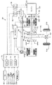
図1は、本発明の一実施例である動力出力装置を搭載したハイブリッド自動車20の構成の概略を示す構成図である。実施例のハイブリッド自動車20は、図示するように、エンジン22と、エンジン22の出力軸としてのクランクシャフト26にダンパ28を介して接続された3軸式の動力分配統合機構30と、動力分配統合機構30に接続された発電可能なモータMG1と、動力分配統合機構30に接続された駆動軸としてのリングギヤ軸32aに取り付けられた減速ギヤ35と、この減速ギヤ35に接続されたモータMG2と、動力出力装置全体をコントロールするハイブリッド用電子制御ユニット70とを備える。
FIG. 1 is a configuration diagram showing an outline of a configuration of a
エンジン22は、例えばガソリンまたは軽油などの炭化水素系の燃料により動力を出力可能な内燃機関として構成されており、図2に示すように、エアクリーナ122により清浄された空気をスロットルバルブ124を介して吸入する共に燃料噴射弁126からガソリンを噴射して吸入された空気とガソリンとを混合し、この混合気を吸気バルブ128を介して燃料室に吸入し、点火プラグ130による電気火花によって爆発燃焼させて、そのエネルギにより押し下げられるピストン132の往復運動をクランクシャフト26の回転運動に変換する。エンジン22からの排気は、一酸化炭素(CO)や炭化水素(HC),窒素酸化物(NOx)の有害成分を浄化する浄化装置(三元触媒)134を介して外気へ排出される。
The
エンジン22は、エンジン用電子制御ユニット(以下、エンジンECUという)24により制御されている。エンジンECU24には、エンジン22の状態を検出する種々のセンサからの信号が図示しない入力ポートを介して入力されている。例えば、エンジンECU24には、クランクシャフト26の回転位置を検出するクランクポジションセンサ140からのクランクポジションやエンジン22の冷却水の温度を検出する水温センサ142からの冷却水温,燃焼室へ吸排気を行なう吸気バルブ128や排気バルブを開閉するカムシャフトの回転位置を検出するカムポジションセンサ144からのカムポジション,スロットルバルブ124のポジションを検出するスロットルバルブポジションセンサ146からのスロットルポジション,エンジン22の負荷としての吸入空気量を検出するバキュームセンサ148からの吸入空気量などが入力ポートを介して入力されている。また、エンジンECU24からは、エンジン22を駆動するための種々の制御信号が図示しない出力ポートを介して出力されている。例えば、エンジンECU24からは、燃料噴射弁126への駆動信号や、スロットルバルブ124のポジションを調節するスロットルモータ136への駆動信号、イグナイタと一体化されたイグニッションコイル138への制御信号、吸気バルブ128の開閉タイミングの変更可能な可変バルブタイミング機構150への制御信号などが出力ポートを介して出力されている。なお、エンジンECU24は、ハイブリッド用電子制御ユニット70と通信しており、ハイブリッド用電子制御ユニット70からの制御信号によりエンジン22を運転制御すると共に必要に応じてエンジン22の運転状態に関するデータを出力する。
The
動力分配統合機構30は、外歯歯車のサンギヤ31と、このサンギヤ31と同心円上に配置された内歯歯車のリングギヤ32と、サンギヤ31に噛合すると共にリングギヤ32に噛合する複数のピニオンギヤ33と、複数のピニオンギヤ33を自転かつ公転自在に保持するキャリア34とを備え、サンギヤ31とリングギヤ32とキャリア34とを回転要素として差動作用を行なう遊星歯車機構として構成されている。動力分配統合機構30は、キャリア34にはエンジン22のクランクシャフト26が、サンギヤ31にはモータMG1が、リングギヤ32にはリングギヤ軸32aを介して減速ギヤ35がそれぞれ連結されており、モータMG1が発電機として機能するときにはキャリア34から入力されるエンジン22からの動力をサンギヤ31側とリングギヤ32側にそのギヤ比に応じて分配し、モータMG1が電動機として機能するときにはキャリア34から入力されるエンジン22からの動力とサンギヤ31から入力されるモータMG1からの動力を統合してリングギヤ32側に出力する。リングギヤ32に出力された動力は、リングギヤ軸32aからギヤ機構60およびデファレンシャルギヤ62を介して、最終的には車両の駆動輪63a,63bに出力される。
The power distribution and
モータMG1およびモータMG2は、いずれも発電機として駆動することができると共に電動機として駆動できる周知の同期発電電動機として構成されており、インバータ41,42を介してバッテリ50と電力のやりとりを行なう。インバータ41,42とバッテリ50とを接続する電力ライン54は、各インバータ41,42が共用する正極母線および負極母線として構成されており、モータMG1,MG2のいずれかで発電される電力を他のモータで消費することができるようになっている。モータMG1,MG2は、いずれもモータ用電子制御ユニット(以下、モータECUという)40により駆動制御されている。モータECU40には、モータMG1,MG2を駆動制御するために必要な信号、例えばモータMG1,MG2の回転子の回転位置を検出する回転位置検出センサ43,44からの信号や図示しない電流センサにより検出されるモータMG1,MG2に印加される相電流などが入力されており、モータECU40からは、インバータ41,42へのスイッチング制御信号が出力されている。モータECU40は、ハイブリッド用電子制御ユニット70と通信しており、ハイブリッド用電子制御ユニット70からの制御信号によってモータMG1,MG2を駆動制御すると共に必要に応じてモータMG1,MG2の運転状態に関するデータをハイブリッド用電子制御ユニット70に出力する。
The motor MG1 and the motor MG2 are both configured as well-known synchronous generator motors that can be driven as generators and can be driven as motors, and exchange power with the
バッテリ50は、バッテリ用電子制御ユニット(以下、バッテリECUという)52によって管理されている。バッテリECU52には、バッテリ50を管理するのに必要な信号、例えば、バッテリ50の端子間に設置された図示しない電圧センサからの端子間電圧,バッテリ50の出力端子に接続された電力ライン54に取り付けられた図示しない電流センサからの充放電電流,バッテリ50に取り付けられた温度センサ51からのバッテリ温度Tbなどが入力されており、必要に応じてバッテリ50の状態に関するデータを通信によりハイブリッド用電子制御ユニット70に出力する。なお、バッテリECU52では、バッテリ50を管理するために電流センサにより検出された充放電電流の積算値に基づいて残容量(SOC)も演算している。
The
ハイブリッド用電子制御ユニット70は、CPU72を中心とするマイクロプロセッサとして構成されており、CPU72の他に処理プログラムを記憶するROM74と、データを一時的に記憶するRAM76と、図示しない入出力ポートおよび通信ポートとを備える。ハイブリッド用電子制御ユニット70には、イグニッションスイッチ80からのイグニッション信号,シフトレバー81の操作位置を検出するシフトポジションセンサ82からのシフトポジションSP,アクセルペダル83の踏み込み量を検出するアクセルペダルポジションセンサ84からのアクセル開度Acc,ブレーキペダル85の踏み込み量を検出するブレーキペダルポジションセンサ86からのブレーキペダルポジションBP,車速センサ88からの車速Vなどが入力ポートを介して入力されている。ハイブリッド用電子制御ユニット70は、前述したように、エンジンECU24やモータECU40,バッテリECU52と通信ポートを介して接続されており、エンジンECU24やモータECU40,バッテリECU52と各種制御信号やデータのやりとりを行なっている。
The hybrid
次に、こうして構成された実施例のハイブリッド自動車20の動作、特にエンジン22の始動時の動作について説明する。図3は、ハイブリッド用電子制御ユニット70により実行される始動時制御ルーチンの一例を示すフローチャートである。このルーチンは、所定時間毎(例えば8msec毎)に繰り返し実行される。
Next, the operation of the
始動時制御ルーチンが実行されると、ハイブリッド用電子制御ユニット70のCPU72は、まず、アクセルペダルポジションセンサ84からのアクセル開度Accや車速センサ88からの車速V,モータMG1,MG2の回転数Nm1,Nm2,エンジン22の回転数Ne,エンジン22の冷却水温度Tw,バッテリ50の温度Tb,バッテリ50の入出力制限Win,Woutなど制御に必要なデータを入力する処理を実行する(ステップS100)。ここで、エンジン22の回転数Neはクランクシャフト26に取り付けられたクランクポジションセンサ23aからの信号に基づいて計算されたものをエンジンECU24から通信により入力するものとし、冷却水温度Twはエンジン22の冷却水の流路に取り付けられた温度センサ142により検出されたものをエンジンECU24から通信により入力するものとした。また、モータMG1,MG2の回転数Nm1,Nm2は、回転位置検出センサ43,44により検出されるモータMG1,MG2の回転子の回転位置に基づいて計算されたものをモータECU40から通信により入力するものとした。さらに、バッテリ50の温度Tbは、バッテリ50に取り付けられた温度センサ51により検出したものをバッテリECU52から通信により入力するものとし、バッテリ50の入出力制限Win,Woutは、温度センサ51により検出されたバッテリ50の温度Tbとバッテリ50の残容量(SOC)とに基づいて設定されたものをバッテリECU52から通信により入力するものとした。ここで、バッテリ50の入出力制限Win,Woutは、バッテリ温度Tbに基づいて入出力制限Win,Woutの基本値を設定し、バッテリ50の残容量(SOC)に基づいて出力制限用補正係数と入力制限用補正係数とを設定し、設定した入出力制限Win,Woutの基本値に補正係数を乗じて入出力制限Win,Woutを設定することができる。図4にバッテリ温度Tbと入出力制限Win,Woutとの関係の一例を示し、図5にバッテリ50の残容量(SOC)と入出力制限Win,Woutの補正係数との関係の一例を示す。
When the start-up control routine is executed, the
こうしてデータを入力すると、入力したアクセル開度Accと車速Vとに基づいて車両に要求されるトルクとして駆動輪63a,63bに連結された駆動軸としてのリングギヤ軸32aに出力すべき要求トルクTr*を設定する(ステップS110)。要求トルクTr*は、実施例では、アクセル開度Accと車速Vと要求トルクTr*との関係を予め定めて要求トルク設定用マップとしてROM74に記憶しておき、アクセル開度Accと車速Vとが与えられると記憶したマップから対応する要求トルクTr*を導出して設定するものとした。図6に要求トルク設定用マップの一例を示す。
When the data is thus input, the required torque Tr * to be output to the
こうして要求トルクTr*を設定すると、冷却水温度TWが閾値Tw1を超えているか否か、バッテリ温度Tbが閾値Tb1を超えているか否か、バッテリ50の出力制限Woutが閾値W1を超えているか否かを判定する(ステップS120)。ここで、閾値Tw1は、エンジン22の始動性が悪くなる冷却水の温度として設定されている。また、閾値Tb1はバッテリ50から通常に電力供給を行なうことができなくなる温度として設定されており、閾値W1はモータMG2で反力をとってモータMG1によりエンジン22を通常にモータリングすることができなくなる可能性がある電力として設定されている。これらの閾値は、エンジン22やモータMG1やモータMG2,バッテリ50の特性により定めることができる。したがって、冷却水温度TWが閾値Tw1を超えており、バッテリ温度Tbが閾値Tb1を超えており、且つ、バッテリ50の出力制限Woutが閾値W1を超えているときには、エンジン22を通常通りモータリングして始動することができることとなり、冷却水温度TWが閾値Tw1を超えていないときやバッテリ温度Tbが閾値Tb1を超えていないとき或いはバッテリ50の出力制限Woutが閾値W1を超えていないときにはエンジン22を通常通りモータリングして始動することができない可能性があることになる。
When the required torque Tr * is thus set, whether the coolant temperature TW exceeds the threshold value Tw1, whether the battery temperature Tb exceeds the threshold value Tb1, or whether the output limit Wout of the
冷却水温度TWが閾値Tw1を超えており、バッテリ温度Tbが閾値Tb1を超えており、且つ、バッテリ50の出力制限Woutが閾値W1を超えているときには、エンジン22を通常通りモータリングして始動することができると判断し、エンジン22の回転数が閾値Nrefより大きいか否かを判定する(ステップS130)。ここで、閾値Nrefは、エンジン22の回転により車両や車両に搭載された機器などが共振する共振回転数領域の上限回転数やこの回転数より大きな回転数として設定されるものであり、エンジン22やこれを搭載する車両を用いて実験などにより定めることができる。なお、実施例では、共振回転数領域の上限回転数より大きな回転数として設定した。エンジン22の回転数Neが閾値Nref以下のときには、エンジン22の回転数Neに基づいてモータMG1のトルク指令Tm1*を設定する(ステップS150)。モータMG1のトルク指令Tm1*とエンジン22の回転数Neとの関係の一例を図7に示す。モータMG1のトルク指令Tm1*は、図示するように、エンジン22の始動指示がなされた時間t1の直後からレート処理を用いて比較的大きなトルクをトルク指令Tm1*に設定し、エンジン22の回転数Neを迅速に増加させる。エンジン22の回転数Neが共振回転数領域を通過した時間t2以降にトルク指令Tm1*にエンジン22を安定して回転数Nref以上にモータリングできるトルクを設定し、電力消費や駆動軸としてのリングギヤ軸32aにおける反力を小さくする。そして、エンジン22の回転数Neが閾値Nrefに至った時間t3からレート処理を用いてトルク指令Tm1*を値0とし、エンジン22の完爆が判定された時間t5から発電用のトルクをトルク指令Tm1*に設定する。いま、エンジン22の始動指示がなされた直後を考えれば、トルク指令Tm1*には大きなトルクが設定されることになる。このときの動力分配統合機構30の回転要素における力学的な関係を例示する共線図を図8に示す。図中、左のS軸はモータMG1の回転数Nm1であるサンギヤ31の回転数を示し、C軸はエンジン22の回転数Neであるキャリア34の回転数を示し、R軸はモータMG2の回転数Nm2に減速ギヤ35のギヤ比Grを乗じたリングギヤ32の回転数Nrを示す。
When the cooling water temperature TW exceeds the threshold value Tw1, the battery temperature Tb exceeds the threshold value Tb1, and the output limit Wout of the
こうしてモータMG1のトルク指令Tm1*を設定すると、バッテリ50の出力制限Woutと設定したモータMG1のトルク指令Tm1*に現在のモータMG1の回転数Nm1を乗じて得られるモータMG1の消費電力(発電電力)との偏差をモータMG2の回転数Nm2で割ることによりモータMG2から出力してもよいトルクの上限としてのトルク制限Tmaxを次式(1)により計算すると共に(ステップS160)、要求トルクTr*とトルク指令Tm1*と動力分配統合機構30のギヤ比ρを用いてモータMG2から出力すべきトルクとしての仮モータトルクTm2tmpを式(2)により計算し(ステップS170)、計算したトルク制限Tmaxと仮モータトルクTm2tmpとを比較して小さい方をモータMG2のトルク指令Tm2*として設定する(ステップS180)。このようにモータMG2のトルク指令Tm2*を設定することにより、駆動軸としてのリングギヤ軸32aに出力する要求トルクTr*を、バッテリ50の出力制限の範囲内で制限したトルクとして設定することができる。なお、式(2)は、前述した図8の共線図から容易に導き出すことができる。
When the torque command Tm1 * of the motor MG1 is set in this way, the power consumption (generated power) of the motor MG1 obtained by multiplying the output limit Wout of the
Tmax=(Wout−Tm1*・Nm1)/Nm2 …(1)
Tm2tmp=(Tr*+Tm1*/ρ)/Gr …(2)
Tmax = (Wout−Tm1 * ・ Nm1) / Nm2 (1)
Tm2tmp = (Tr * + Tm1 * / ρ) / Gr (2)
こうしてモータMG1,MG2のトルク指令Tm1*,Tm2*を設定すると、設定したトルク指令Tm1*,Tm2*をモータECU40に送信し(ステップS190)、始動時制御ルーチンを終了する。トルク指令Tm1*,Tm2*を受信したモータECU40は、トルク指令Tm1*でモータMG1が駆動されると共にトルク指令Tm2*でモータMG2が駆動されるようインバータ41,42のスイッチング素子のスイッチング制御を行なう。
When the torque commands Tm1 * and Tm2 * for the motors MG1 and MG2 are set in this manner, the set torque commands Tm1 * and Tm2 * are transmitted to the motor ECU 40 (step S190), and the start time control routine is terminated. Receiving the torque commands Tm1 * and Tm2 *, the
こうした始動時制御ルーチンが繰り返し実行されるうちに、エンジン22の回転数Neが閾値Nrefを超えると(ステップS130)、ハイブリッド用電子制御ユニット70はエンジンECU24に燃料噴射制御の開始を指示し(ステップS140)、ステップS150以降の処理を実行する。これにより、エンジンECU24は燃料噴射制御と点火制御を開始し、エンジン22を始動する。
If the rotational speed Ne of the
ステップS120で冷却水温度TWが閾値Tw1を超えていないと判定されたり、バッテリ温度Tbが閾値Tb1を超えていないと判定されたり、あるいは、バッテリ50の出力制限Woutが閾値W1を超えていないと判定されたときには、エンジン22を通常通りモータリングして始動することができない可能性があると判断し、エンジン22の回転数Neが共振回転数領域より大きな閾値Nrefを超える前であっても迅速にエンジン22を始動するために、エンジンECU24に燃料噴射制御の開始を指示し(ステップS140)、ステップS150以降の処理を実行する。これにより、エンジンECU24は直ちに燃料噴射制御と点火制御を開始してエンジン22を始動する。
In step S120, it is determined that the coolant temperature TW does not exceed the threshold value Tw1, the battery temperature Tb is determined not to exceed the threshold value Tb1, or the output limit Wout of the
以上説明した実施例のハイブリッド自動車20によれば、エンジン22を始動する際に、バッテリ温度Tbが閾値Tb1を超えていないときやバッテリ50の出力制限Woutが閾値W1を超えていないとき、即ち、バッテリ50の状態によりエンジン22を通常通りにモータリングできない可能性があるときには、エンジン22の回転数Neが共振回転数領域より大きな閾値Nrefを超える前にエンジンECU24による燃料噴射制御や点火制御を開始するから、エンジン22をより確実に始動することができる。また、冷却水温度TWが閾値Tw1を超えていないことによりエンジン22の始動性が悪いときにもエンジン22の回転数Neが共振回転数領域より大きな閾値Nrefを超える前にエンジンECU24による燃料噴射制御や点火制御を開始することにより、エンジン22をより確実に始動することができる。もとより、バッテリ50がエンジン22を通常通りにモータリングできる状態のときには、エンジン22の回転数Neが共振回転数領域より大きな閾値Nrefを超えてからエンジンECU24による燃料噴射制御や点火制御を開始するから、エンジン22の始動時に生じ得る共振を抑制することができる。
According to the
実施例のハイブリッド自動車20では、エンジン22を始動する際に、バッテリ温度Tbが閾値Tb1を超えていないときやバッテリ50の出力制限Woutが閾値W1を超えていないときにバッテリ50の状態によりエンジン22を通常通りにモータリングできない可能性があると判定し、エンジン22の回転数Neが共振回転数領域より大きな閾値Nrefを超える前にエンジンECU24による燃料噴射制御や点火制御を開始してエンジン22を始動するものとしたが、バッテリ50の状態によりエンジン22を通常通りにモータリングできない可能性があると判定できる場合には、他の要件によってもエンジン22の回転数Neが共振回転数領域より大きな閾値Nrefを超える前にエンジンECU24による燃料噴射制御や点火制御を開始してエンジン22を始動するものとしてもよい。例えば、バッテリ50の残容量(SOC)によりエンジン22を通常通りモータリングできない可能性があると判定できるときなどが該当する。
In the
実施例のハイブリッド自動車20では、エンジン22を通常通りモータリングできるときには、エンジン22の回転数が共振回転数領域より大きな回転数(閾値Nref)を超えたときにエンジンECU24による燃料噴射制御や点火制御を開始してエンジン22を始動するものとしたが、エンジン22の回転数が共振回転数領域の上限回転数に至ったときにエンジンECU24による燃料噴射制御や点火制御を開始してエンジン22を始動するものとしてもよい。
In the
実施例のハイブリッド自動車20では、エンジン22として吸気マニホールドに燃料噴射弁126を取り付けて吸気マニホールド内に燃料を噴射して混合気を燃焼室に供給するタイプの内燃機関を用いたが、燃焼室に燃料噴射弁を取り付けて燃焼室に燃料を直接噴射するタイプの内燃機関を用いるものとしてもよい。
In the
実施例では、エンジン22と動力分配統合機構30と二つのモータMG1,MG2とバッテリ50とを備えるハイブリッド自動車20のエンジン22の始動に本発明を適用したが、エンジンとエンジンを共振回転数領域を超える回転数となるまでモータリング可能なモータとモータに電力を供給するバッテリを備える構成であれば如何なる構成の装置としても差し支えない。この場合、この装置を車両に搭載する場合、いわゆるアイドルストップ制御におけるエンジンの自動始動やエンジンの間欠運転における自動始動に適用するものとしてもよい。また、こうしたエンジンの自動始動以外の始動に適用するものとしてもよい。さらに、エンジンとエンジンを共振回転数領域を超える回転数となるまでモータリング可能なモータとモータに電力を供給するバッテリを備える構成の装置を、自動車以外の車両や船舶,航空機などの移動体に搭載するものとしてもよいし、建設機械などの移動体以外の設備に組み込むものとしても構わない。また、内燃機関の始動装置としての形態の他、内燃機関の始動方法の形態としてもよい。
In the embodiment, the present invention is applied to start the
以上、本発明を実施するための最良の形態について実施例を用いて説明したが、本発明はこうした実施例に何等限定されるものではなく、本発明の要旨を逸脱しない範囲内において、種々なる形態で実施し得ることは勿論である。 The best mode for carrying out the present invention has been described with reference to the embodiments. However, the present invention is not limited to these embodiments, and various modifications can be made without departing from the gist of the present invention. Of course, it can be implemented in the form.
20 ハイブリッド自動車、22 エンジン、23 温度センサ、24 エンジン用電子制御ユニット(エンジンECU)、26 クランクシャフト、28 ダンパ、30 動力分配統合機構、31 サンギヤ、32 リングギヤ、32a リングギヤ軸、33 ピニオンギヤ、34 キャリア、35,減速ギヤ、40 モータ用電子制御ユニット(モータECU)、41,42 インバータ、43,44 回転位置検出センサ、50 バッテリ、51 温度センサ、52 バッテリ用電子制御ユニット(バッテリECU)、54 電力ライン、60 ギヤ機構、62 デファレンシャルギヤ、63a,63b 駆動輪、70 ハイブリッド用電子制御ユニット、72 CPU、74 ROM、76 RAM、80 イグニッションスイッチ、81 シフトレバー、82 シフトポジションセンサ、83 アクセルペダル、84 アクセルペダルポジションセンサ、85 ブレーキペダル、86 ブレーキペダルポジションセンサ、88 車速センサ、122 エアクリーナ、124 スロットルバルブ、126 用燃料噴射弁、128 吸気バルブ、130 点火プラグ、132 ピストン、134 浄化装置、136,スロットルモータ、138 イグニッションコイル、140 クランクポジションセンサ、142 水温センサ、144 カムポジションセンサ、146 スロットルバルブポジションセンサ、150 可変バルブタイミング機構、MG1,MG2 モータ。 20 hybrid vehicle, 22 engine, 23 temperature sensor, 24 engine electronic control unit (engine ECU), 26 crankshaft, 28 damper, 30 power distribution and integration mechanism, 31 sun gear, 32 ring gear, 32a ring gear shaft, 33 pinion gear, 34 carrier , 35, reduction gear, 40 motor electronic control unit (motor ECU), 41, 42 inverter, 43, 44 rotational position detection sensor, 50 battery, 51 temperature sensor, 52 battery electronic control unit (battery ECU), 54 electric power Line, 60 gear mechanism, 62 differential gear, 63a, 63b drive wheel, 70 hybrid electronic control unit, 72 CPU, 74 ROM, 76 RAM, 80 ignition switch, 81 shift lever , 82 Shift position sensor, 83 Accelerator pedal, 84 Accelerator pedal position sensor, 85 Brake pedal, 86 Brake pedal position sensor, 88 Vehicle speed sensor, 122 Air cleaner, 124 Throttle valve, 126 Fuel injection valve, 128 Intake valve, 130 Spark plug , 132 piston, 134 purification device, 136, throttle motor, 138 ignition coil, 140 crank position sensor, 142 water temperature sensor, 144 cam position sensor, 146 throttle valve position sensor, 150 variable valve timing mechanism, MG1, MG2 motor.
Claims (6)
前記内燃機関をモータリング可能な電動機と、
該電動機に電力を供給可能な蓄電手段と、
該蓄電手段の状態を検出する状態検出手段と、
所定の始動指示がなされたとき、前記内燃機関がモータリングされるよう前記電動機を駆動制御すると共に、前記状態検出手段により検出された前記蓄電手段の状態が通常状態であるときには前記内燃機関が共振回転数領域の上限回転数に至った以降に該内燃機関への燃料噴射制御を開始して該内燃機関が始動されるよう制御し、前記状態検出手段により検出された前記蓄電手段の状態が通常状態ではないときには前記内燃機関が共振回転数領域の上限回転数に至る前に該内燃機関への燃料噴射制御を開始して該内燃機関が始動されるよう制御する制御手段と、
を備える内燃機関の始動装置。 An internal combustion engine starter for starting an internal combustion engine,
An electric motor capable of motoring the internal combustion engine;
Power storage means capable of supplying power to the motor;
State detecting means for detecting the state of the power storage means;
When a predetermined start instruction is given, the electric motor is driven and controlled so that the internal combustion engine is motored, and the internal combustion engine is resonated when the state of the power storage means detected by the state detection means is a normal state. The fuel injection control to the internal combustion engine is started after reaching the upper limit rotational speed in the rotational speed region, and the internal combustion engine is controlled to start, and the state of the power storage means detected by the state detection means is normal. Control means for starting the fuel injection control to the internal combustion engine and starting the internal combustion engine before the internal combustion engine reaches the upper limit rotational speed in the resonance rotational speed region when not in a state;
An internal combustion engine starter comprising:
前記状態検出手段は、前記蓄電手段の温度を検出する手段であり、
前記制御手段は、前記状態検出手段により検出された温度が所定温度以下のときに前記蓄電手段の状態が通常状態でないとして制御する手段である
内燃機関の始動装置。 An internal combustion engine starter according to claim 1,
The state detection means is means for detecting the temperature of the power storage means,
The starter of an internal combustion engine, wherein the control means is a means for controlling that the state of the power storage means is not a normal state when the temperature detected by the state detection means is equal to or lower than a predetermined temperature.
前記状態検出手段は、前記蓄電手段の出力制限を検出する手段であり、
前記制御手段は、前記状態検出手段により検出された出力制限が所定値以下のときに前記蓄電手段の状態が通常状態でないとして制御する手段である
内燃機関の始動装置。 An internal combustion engine starter according to claim 1 or 2,
The state detection means is means for detecting an output limit of the power storage means,
The starter for an internal combustion engine, wherein the control means is a means for controlling that the state of the power storage means is not a normal state when the output limit detected by the state detection means is not more than a predetermined value.
前記状態検出手段は、前記蓄電手段の蓄電量を検出する手段であり、
前記制御手段は、前記状態検出手段により検出された蓄電量が所定量以下のときに前記蓄電手段の状態が通常状態でないとして制御する手段である
内燃機関の始動装置。 An internal combustion engine starter according to any one of claims 1 to 3,
The state detection means is means for detecting the amount of electricity stored in the electricity storage means,
The starter for an internal combustion engine, wherein the control means is a means for controlling that the state of the power storage means is not a normal state when the amount of power detected by the state detection means is equal to or less than a predetermined amount.
前記内燃機関を冷却する冷却媒体の温度を検出する冷却媒体温度検出手段を備え、
前記制御手段は、前記状態検出手段により検出された前記蓄電手段の状態が通常状態であるときでも前記前記冷却媒体温度検出手段により検出された冷却媒体の温度が所定温度以下のときには前記内燃機関が共振回転数領域の上限回転数に至る前に該内燃機関への燃料噴射制御を開始して該内燃機関が始動されるよう制御する手段である
内燃機関の始動装置。 An internal combustion engine starter according to any one of claims 1 to 4,
A cooling medium temperature detecting means for detecting a temperature of a cooling medium for cooling the internal combustion engine;
When the temperature of the cooling medium detected by the cooling medium temperature detecting means is not more than a predetermined temperature even when the state of the power storage means detected by the state detecting means is a normal state, the control means A starter for an internal combustion engine, which is means for starting fuel injection control to the internal combustion engine and starting the internal combustion engine before reaching an upper limit rotational speed in a resonance rotational speed region.
前記内燃機関をモータリングするよう前記電動機を駆動すると共に前記蓄電手段の状態を検出し、
前記検出した蓄電手段の状態が通常状態であるときには前記内燃機関が共振回転数領域の上限回転数に至った以降に該内燃機関への燃料噴射制御を開始して該内燃機関を始動し、前記検出した蓄電手段の状態が通常状態ではないときには前記内燃機関が共振回転数領域の上限回転数に至る前に該内燃機関への燃料噴射制御を開始して該内燃機関を始動する
内燃機関の始動方法。 A method of starting the internal combustion engine in a drive device comprising an internal combustion engine, an electric motor capable of motoring the internal combustion engine, and an electric storage means capable of supplying electric power to the electric motor,
Driving the electric motor to motor the internal combustion engine and detecting the state of the power storage means;
When the detected state of the power storage means is a normal state, after the internal combustion engine reaches the upper limit rotational speed in the resonance rotational speed region, fuel injection control to the internal combustion engine is started to start the internal combustion engine, When the detected state of the power storage means is not the normal state, the fuel injection control to the internal combustion engine is started and the internal combustion engine is started before the internal combustion engine reaches the upper limit rotational speed in the resonance rotational speed region. Method.
Priority Applications (1)
| Application Number | Priority Date | Filing Date | Title |
|---|---|---|---|
| JP2004085198A JP2005273490A (en) | 2004-03-23 | 2004-03-23 | STARTING DEVICE AND STARTING METHOD FOR INTERNAL COMBUSTION ENGINE |
Applications Claiming Priority (1)
| Application Number | Priority Date | Filing Date | Title |
|---|---|---|---|
| JP2004085198A JP2005273490A (en) | 2004-03-23 | 2004-03-23 | STARTING DEVICE AND STARTING METHOD FOR INTERNAL COMBUSTION ENGINE |
Publications (1)
| Publication Number | Publication Date |
|---|---|
| JP2005273490A true JP2005273490A (en) | 2005-10-06 |
Family
ID=35173442
Family Applications (1)
| Application Number | Title | Priority Date | Filing Date |
|---|---|---|---|
| JP2004085198A Pending JP2005273490A (en) | 2004-03-23 | 2004-03-23 | STARTING DEVICE AND STARTING METHOD FOR INTERNAL COMBUSTION ENGINE |
Country Status (1)
| Country | Link |
|---|---|
| JP (1) | JP2005273490A (en) |
Cited By (6)
| Publication number | Priority date | Publication date | Assignee | Title |
|---|---|---|---|---|
| JP2007230474A (en) * | 2006-03-03 | 2007-09-13 | Suzuki Motor Corp | Engine start control device for hybrid vehicle |
| JP2010216381A (en) * | 2009-03-17 | 2010-09-30 | Honda Motor Co Ltd | Internal combustion engine starter |
| JP2012241526A (en) * | 2011-05-16 | 2012-12-10 | Nissan Motor Co Ltd | Automatic stop restart device of engine |
| CN103423056A (en) * | 2012-05-21 | 2013-12-04 | 上海汽车集团股份有限公司 | Method for controlling abnormal starting up of hybrid power system |
| US10393046B2 (en) | 2017-01-27 | 2019-08-27 | Toyota Jidosha Kabushiki Kaisha | Control apparatus for vehicle |
| JP2020176554A (en) * | 2019-04-18 | 2020-10-29 | トヨタ自動車株式会社 | Internal combustion engine control device |
-
2004
- 2004-03-23 JP JP2004085198A patent/JP2005273490A/en active Pending
Cited By (7)
| Publication number | Priority date | Publication date | Assignee | Title |
|---|---|---|---|---|
| JP2007230474A (en) * | 2006-03-03 | 2007-09-13 | Suzuki Motor Corp | Engine start control device for hybrid vehicle |
| JP2010216381A (en) * | 2009-03-17 | 2010-09-30 | Honda Motor Co Ltd | Internal combustion engine starter |
| JP2012241526A (en) * | 2011-05-16 | 2012-12-10 | Nissan Motor Co Ltd | Automatic stop restart device of engine |
| CN103423056A (en) * | 2012-05-21 | 2013-12-04 | 上海汽车集团股份有限公司 | Method for controlling abnormal starting up of hybrid power system |
| US10393046B2 (en) | 2017-01-27 | 2019-08-27 | Toyota Jidosha Kabushiki Kaisha | Control apparatus for vehicle |
| JP2020176554A (en) * | 2019-04-18 | 2020-10-29 | トヨタ自動車株式会社 | Internal combustion engine control device |
| JP7283199B2 (en) | 2019-04-18 | 2023-05-30 | トヨタ自動車株式会社 | Control device for internal combustion engine |
Similar Documents
| Publication | Publication Date | Title |
|---|---|---|
| JP4175371B2 (en) | INTERNAL COMBUSTION ENGINE DEVICE, ITS CONTROL METHOD, AND POWER OUTPUT DEVICE | |
| CN101421499B (en) | Variable valve device, control method thereof, and vehicle equipped with the variable valve device | |
| JP4123254B2 (en) | Internal combustion engine misfire determination device and internal combustion engine misfire determination method | |
| JP4175361B2 (en) | Hybrid vehicle and control method thereof | |
| JP4301066B2 (en) | Automatic stop / start device for internal combustion engine and automobile equipped with the same | |
| JP4207966B2 (en) | POWER OUTPUT DEVICE, ITS CONTROL METHOD, AND VEHICLE | |
| CN105545502A (en) | Hybrid vehicle | |
| JP4730329B2 (en) | POWER OUTPUT DEVICE, ITS CONTROL METHOD, AND VEHICLE | |
| JP5904131B2 (en) | Hybrid vehicle control device and hybrid vehicle | |
| JP4779800B2 (en) | Vehicle and control method thereof | |
| JP2005273490A (en) | STARTING DEVICE AND STARTING METHOD FOR INTERNAL COMBUSTION ENGINE | |
| JP4196960B2 (en) | Power output apparatus, automobile equipped with the same, and control method therefor | |
| JP2006070820A (en) | Drive device, automobile equipped with the same and method for controlling the drive device | |
| JP2007313948A (en) | Automobile and control method thereof | |
| JP2013067297A (en) | Hybrid vehicle | |
| JP2009279965A (en) | Hybrid vehicle and method of controlling the same | |
| JP4862687B2 (en) | Internal combustion engine device, power output device, and control method thereof | |
| JP2010024891A (en) | Automobile and its control method | |
| JP2006347430A (en) | Hybrid vehicle and control method thereof | |
| JP2007309113A (en) | POWER OUTPUT DEVICE, VEHICLE HAVING THE SAME, AND METHOD FOR CONTROLLING POWER OUTPUT DEVICE | |
| JP4438752B2 (en) | POWER OUTPUT DEVICE, ITS CONTROL METHOD, AND VEHICLE | |
| JP4229117B2 (en) | Power output device, automobile equipped with the same, and control method of power output device | |
| JP2007291935A (en) | INTERNAL COMBUSTION ENGINE DEVICE, VEHICLE HAVING SAME, AND METHOD FOR CONTROLLING INTERNAL COMBUSTION ENGINE DEVICE | |
| JP2007120382A (en) | POWER OUTPUT DEVICE, ITS CONTROL METHOD, AND VEHICLE | |
| JP2006316663A (en) | POWER OUTPUT DEVICE AND METHOD FOR STARTING INTERNAL COMBUSTION ENGINE EQUIPPED WITH THE SAME |
Legal Events
| Date | Code | Title | Description |
|---|---|---|---|
| A621 | Written request for application examination |
Free format text: JAPANESE INTERMEDIATE CODE: A621 Effective date: 20060607 |
|
| A131 | Notification of reasons for refusal |
Free format text: JAPANESE INTERMEDIATE CODE: A131 Effective date: 20061212 |
|
| A02 | Decision of refusal |
Free format text: JAPANESE INTERMEDIATE CODE: A02 Effective date: 20071016 |