JP2005240633A - Muffler structure - Google Patents
Muffler structure Download PDFInfo
- Publication number
- JP2005240633A JP2005240633A JP2004050030A JP2004050030A JP2005240633A JP 2005240633 A JP2005240633 A JP 2005240633A JP 2004050030 A JP2004050030 A JP 2004050030A JP 2004050030 A JP2004050030 A JP 2004050030A JP 2005240633 A JP2005240633 A JP 2005240633A
- Authority
- JP
- Japan
- Prior art keywords
- resonator
- engine speed
- shell
- chamber
- slide mechanism
- Prior art date
- Legal status (The legal status is an assumption and is not a legal conclusion. Google has not performed a legal analysis and makes no representation as to the accuracy of the status listed.)
- Pending
Links
Images



Landscapes
- Exhaust Silencers (AREA)
Abstract
【課題】本発明は、エンジン回転数や排気温度をモニタリングし、エンジン回転数と排気温度とによりレゾネータ容積を調整し、低減したい燃料n次の周波数とマフラの共振周波数とを広い範囲で一致させ、高い消音効果を得ることを目的としている。
【解決手段】このため、シェルの両端を夫々エンドプレートで閉塞し、内部をバッフルプレートによりレゾネータ室と拡張室とに区画し、レゾネータ室にインレットパイプの下流側を開口させ、拡張室にアウトレットパイプの上流側を開口させたマフラ構造において、シェルを内側シェルと外側シェルとで構成し、内側シェルと外側シェルとの間にスライド機構を設け、スライド機構によりレゾネータ室を可変に構成し、エンドプレートの後側に筒部を設け、筒部にシールリングを介してアウトレットパイプを挿通させ、スライド機構をエンジンの回転数と排気温度とにより所定位置に駆動する制御部を備えている。
【選択図】図1The present invention monitors engine speed and exhaust temperature, adjusts the resonator volume based on engine speed and exhaust temperature, and matches the fuel n-th order frequency to be reduced and the resonance frequency of the muffler over a wide range. The purpose is to obtain a high silencing effect.
For this purpose, both ends of the shell are respectively closed by end plates, the inside is partitioned into a resonator chamber and an expansion chamber by a baffle plate, the downstream side of the inlet pipe is opened in the resonator chamber, and the outlet pipe is opened in the expansion chamber In the muffler structure with the upstream side opened, the shell is composed of an inner shell and an outer shell, a slide mechanism is provided between the inner shell and the outer shell, and the resonator chamber is variably configured by the slide mechanism, and the end plate A cylinder part is provided on the rear side, and an outlet pipe is inserted into the cylinder part via a seal ring, and a control unit is provided to drive the slide mechanism to a predetermined position by the engine speed and the exhaust temperature.
[Selection] Figure 1
Description
この発明はマフラ構造に係り、特にエンジン回転数と排気温度とをモニタリングし、エンジン回転数と排気温度との変化に応じてレゾネータ室の容積を変更して高い消音効果を期待するマフラ構造に関するものである。 The present invention relates to a muffler structure, and more particularly to a muffler structure that monitors the engine speed and the exhaust temperature and expects a high noise reduction effect by changing the volume of the resonator chamber according to changes in the engine speed and the exhaust temperature. It is.
自動車においては、排気音等の騒音の低減を果たすべく、排気系に消音機能を有するマフラが装着されている。 In an automobile, a muffler having a silencing function is attached to an exhaust system in order to reduce noise such as exhaust noise.
ところで、従来のマフラ構造の一般的な消音器においては、レゾネータ室の容積が一定であったため、マフラの減衰周波数が固定されており、特定の減衰周波数のみでしか消音機能を発揮させることができないという不都合がある。 By the way, in a conventional muffler having a conventional muffler structure, since the volume of the resonator chamber is constant, the attenuation frequency of the muffler is fixed, and the muffler function can be exhibited only with a specific attenuation frequency. There is an inconvenience.
上述した不都合を解消する消音器(上述の特許文献1参照)が既に開示されている。この消音器は、管路の途中に空洞を設け、処理しようとする音響の周波数特性、つまり騒音の周波数成分の値の変化に応じて前記空洞の長さを可変とすべく構成している。 There has already been disclosed a silencer (see Patent Document 1 described above) that solves the above-described disadvantages. This silencer is configured so that a cavity is provided in the middle of the pipe and the length of the cavity is made variable in accordance with the change in the frequency characteristics of the sound to be processed, that is, the frequency component of the noise.
しかし、エンジン回転数や排気温度に対しても排気音の周波数は変化するため、期待通りの消音効果を得ることが困難であるという不都合がある。 However, since the frequency of the exhaust sound changes with respect to the engine speed and the exhaust temperature, there is an inconvenience that it is difficult to obtain the expected silencing effect.
よって、この発明は、エンジン回転数や排気温度をモニタリングし、制御部にてスライド機構をエンジンの回転数と排気温度とにより所定位置に駆動してレゾネータ容積を調整する。 Therefore, according to the present invention, the engine speed and the exhaust temperature are monitored, and the control unit drives the slide mechanism to a predetermined position by the engine speed and the exhaust temperature to adjust the resonator volume.
そして、低減したい燃料n次の周波数とマフラの共振周波数とを広い範囲で一致させ、高い消音効果を得ることを目的としている。 An object of the present invention is to obtain a high noise reduction effect by matching the n-th order frequency of the fuel to be reduced and the resonance frequency of the muffler over a wide range.
そこで、この発明は、上述不都合を除去するために、シェルの両端を夫々エンドプレートで閉塞するとともに内部をバッフルプレートによりレゾネータ室と拡張室とに区画し、前記レゾネータ室にインレットパイプの下流側を開口させ、前記拡張室にアウトレットパイプの上流側を開口させたマフラ構造において、前記シェルを内側シェルと外側シェルとで構成し、前記内側シェルと外側シェルとの間にスライド機構を設け、前記スライド機構により前記レゾネータ室を可変に構成し、前記エンドプレートの後側に筒部を設け、該筒部にシールリングを介してアウトレットパイプを挿通させるとともに、前記スライド機構をエンジンの回転数と排気温度とにより所定位置に駆動する制御部を備えたことを特徴とする。 Therefore, in order to eliminate the inconvenience described above, the present invention closes both ends of the shell with end plates and partitions the inside into a resonator chamber and an expansion chamber by a baffle plate, and the downstream side of the inlet pipe is connected to the resonator chamber. In the muffler structure in which the upstream side of the outlet pipe is opened in the expansion chamber, the shell is composed of an inner shell and an outer shell, a slide mechanism is provided between the inner shell and the outer shell, and the slide The resonator chamber is configured to be variable by a mechanism, a cylindrical portion is provided on the rear side of the end plate, an outlet pipe is inserted into the cylindrical portion via a seal ring, and the slide mechanism is connected to the engine speed and exhaust temperature. And a control unit for driving to a predetermined position.
以上詳細に説明した如くこの本発明によれば、シェルの両端を夫々エンドプレートで閉塞するとともに内部をバッフルプレートによりレゾネータ室と拡張室とに区画し、レゾネータ室にインレットパイプの下流側を開口させ、拡張室にアウトレットパイプの上流側を開口させたマフラ構造において、シェルを内側シェルと外側シェルとで構成し、内側シェルと外側シェルとの間にスライド機構を設け、スライド機構によりレゾネータ室を可変に構成し、エンドプレートの後側に筒部を設け、筒部にシールリングを介してアウトレットパイプを挿通させるとともに、スライド機構をエンジンの回転数と排気温度とにより所定位置に駆動する制御部を備えたので、エンジン回転数と排気温度とをモニタリングして、エンジン回転数と排気温度とにより前記レゾネータ室の容積を変更することができ、従来消音については考慮されていなかった低次の燃焼次数成分に対しても消音でき、高い消音効果を期待することができる。 As described in detail above, according to the present invention, both ends of the shell are closed by the end plates, and the inside is partitioned into the resonator chamber and the expansion chamber by the baffle plate, and the downstream side of the inlet pipe is opened in the resonator chamber. In the muffler structure where the upstream side of the outlet pipe is opened in the expansion chamber, the shell is composed of an inner shell and an outer shell, a slide mechanism is provided between the inner shell and the outer shell, and the resonator chamber is variable by the slide mechanism And a control unit that drives the slide mechanism to a predetermined position by the engine speed and the exhaust gas temperature. Since the engine speed and exhaust temperature are monitored, the engine speed and exhaust temperature are monitored. Ri wherein it is possible to change the resonator chamber volume, the conventional muffler can also mute the low next combustion order components that have not been considered for, it can be expected a high silencing effect.
上述の如く発明したことにより、エンジン回転数と排気温度とをモニタリングし、エンジン回転数と排気温度との変化に応じてレゾネータ室の容積を変更し、高い消音効果を期待している。 By inventing as described above, the engine speed and the exhaust temperature are monitored, and the volume of the resonator chamber is changed in accordance with changes in the engine speed and the exhaust temperature, so that a high silencing effect is expected.
以下図面に基づいてこの発明の実施例を詳細に説明する。 Embodiments of the present invention will be described below in detail with reference to the drawings.
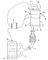
図1〜図4はこの発明の実施例を示すものである。図3において、2は図示しない自動車に搭載されるエンジン(「ENG」とも記載する。)である。 1 to 4 show an embodiment of the present invention. In FIG. 3, reference numeral 2 denotes an engine (also referred to as “ENG”) mounted on a vehicle (not shown).
このエンジン2は、吸気系に図示しない吸気マニホルドの下流側端部が接続されるとともに、排気系に排気マニホルド4の上流側端部が接続される。 In the engine 2, a downstream end portion of an intake manifold (not shown) is connected to the intake system, and an upstream end portion of the exhaust manifold 4 is connected to the exhaust system.
この排気マニホルド4の下流側端部には、図3に示す如く、排気管6が接続されるとともに、排気管6の途中部位に触媒8が配設される。 As shown in FIG. 3, an exhaust pipe 6 is connected to the downstream end of the exhaust manifold 4, and a catalyst 8 is disposed in the middle of the exhaust pipe 6.
また、前記排気管6の下流側端部には、インレットパイプ10を介して可変容量型マフラ12を接続して設ける。
A
この可変容量型マフラ12は、図1に示す如く、シェル14と、このシェル14の両端を夫々閉塞する上流側第1エンドプレート16及び下流側第2エンドプレート18と、シェル14の内部をバッフルプレート20により区画して形成されるレゾネータ室22及び拡張室24と、前記レゾネータ室22に下流側を開口させたインレットパイプ10と、前記拡張室24に上流側を開口させたアウトレットパイプ26とを有している。
As shown in FIG. 1, the variable
そして、前記拡張室24は、区画プレート28により第1、第2拡張室24−1、24−2に区画される。
The
このとき、前記シェル14を内側シェル30と外側シェル32とで構成し、前記内側シェル30と外側シェル32との間にスライド機構34を設け、前記スライド機構34により前記レゾネータ室22を可変に構成し、エンドプレートの後側である前記下流側第2エンドプレート18に筒部36を設け、該筒部36にシールリング38を介して前記アウトレットパイプ26を挿通させるとともに、前記スライド機構34を前記エンジン2のエンジン回転数と排気温度とにより所定位置に駆動する制御部40を備えた構成とする。
At this time, the
詳述すれば、前記スライド機構34は、図1に示す如く、前記内側シェル30の外周面において長手方向、つまりスライド方向に配設したレール42と、内側シェル30の先端に前記外側シェル32の内周面に接触すべく配設したシールリング44と、前記外側シェル32に支持され、前記レール42上を移動するローラ46と、このローラ46を駆動させて前記レゾネータ室22を可変とするモータ48とからなる。
More specifically, as shown in FIG. 1, the
また、図1に示す如く、前記エンジン2にエンジン回転数を検出するエンジン回転数センサ(「回転数計」といもう。)50を配設するとともに、図1及び図3に示す如く、前記可変容量型マフラ12の下流側第2エンドプレート18に排気温度センサ52を配設する。
Further, as shown in FIG. 1, the engine 2 is provided with an engine speed sensor (referred to as “rotometer”) 50 for detecting the engine speed, and as shown in FIGS. An
そして、エンジン回転数センサ50及び排気温度センサ52を、図3に示す如く、前記制御部40のインプット側に接続して設けるとともに、制御部40のアウトプット側には前記モータ48を接続して設ける。
As shown in FIG. 3, an
このとき、制御部40は、エンジン回転数センサ50からのエンジン回転数信号と排気温度センサ52からの排気温度信号とを入力し、これらの検出信号を元に予め設定されたプログラムにより前記スライド機構34のモータ48を所定位置まで駆動させ、前記レゾネータ室22の容積を可変とするものである。
At this time, the
更に、レゾネータ室22の容積は、従来消音については考慮されていなかった低次の燃焼次数成分に対して消音効果を発生するように設定する。
Further, the volume of the
なお、前記制御部40は、エンジン回転数が大きくなるに従い前記レゾネータ室22の容積を減少させるべく制御するとともに、排気温度が高くなるに従い前記レゾネータ室22の容積を増大させるべく制御する。
The
ここで、各種の式を開示して追加説明すると、正比例の関係にある燃焼次数成分とエンジン回転数とは、4サイクル3気筒エンジンの場合に、

また、前記可変容量型マフラ12のレゾネータ室22は、図1に示す如く、ヘルムホルツ共鳴器となっており、図2にはこのヘルムホルツ共鳴器を一般化したものを開示する。
The
更に、ヘルムホルツ共鳴器の共振周波数は、
そして、式(2)中の音速cは、波動方程式により、
ここで、流体を理想気体と見なすと、
よって、エンジン回転数Nと排気温度Tとをモニタリングしつつ、
次に作用を説明する。 Next, the operation will be described.
エンジン回転数が大きくなった場合には、前記制御部40がスライド機構34のモータ48を前記レゾネータ室22の容積減少側に駆動制御する。
When the engine speed increases, the
すなわち、前記モータ48によりローラ46を駆動させて、前記内側シェル30に対して前記外側シェル32を前記レゾネータ室22の容積を減少させる側、つまり図1おいて左側に移動させる。
That is, the
そして、前記可変容量型マフラ12の下流側第2エンドプレート18を移動させ、前記レゾネータ室22の容積を減少させる。
Then, the
また、排気温度が高くなった場合には、前記制御部40がスライド機構34のモータ48を前記レゾネータ室22の容積増加側に駆動制御する。
Further, when the exhaust temperature becomes high, the
すなわち、前記モータ48によりローラ46を駆動させて、前記内側シェル30に対して前記外側シェル32を前記レゾネータ室22の容積を増加させる側、つまり図1おいて右側に移動させる。
That is, the
そして、前記可変容量型マフラ12の下流側第2エンドプレート18を移動させ、前記レゾネータ室22の容積を増加させる。
Then, the
これにより、前記シェル14を内側シェル30と外側シェル32とで構成し、前記内側シェル30と外側シェル32との間にスライド機構34を設け、前記スライド機構34により前記レゾネータ室22を可変に構成し、エンドプレートの後側である前記下流側第2エンドプレート18に筒部36を設け、該筒部36にシールリング38を介して前記アウトレットパイプ26を挿通させるとともに、前記スライド機構34を前記エンジン2のエンジン回転数と排気温度とにより所定位置に駆動する制御部40を備えた構成によって、エンジン回転数と排気温度とをモニタリングして、エンジン回転数と排気温度とにより前記レゾネータ室22の容積を変更することができ、全温度域・全回転数域における消音が可能となり、特に従来消音については考慮されていなかった低次の燃焼次数成分に対しても消音でき、高い消音効果を期待することができる。
As a result, the
また、前記制御部40は、エンジン回転数が大きくなるに従い前記レゾネータ室22の容積を減少させるべく制御することにより、エンジン回転数が大きくなるに従い、周波数が大きくなるのに合わせて前記レゾネータ室22の容積を減少側に変更でき、高い消音効果を期待することができる。
The
更に、前記制御部40は、排気温度が高くなるに従い前記レゾネータ室22の容積を増大させるべく制御することにより、排気温度が高くなるに従い、周波数が低くなるのに合わせて前記レゾネータ室22の容積を増加側に変更でき、高い消音効果を期待することができる。
Further, the
更にまた、エンジン回転数Nと排気温度Tとをモニタリングしつつ、式(7)を満たすように、前記ヘルムホルツ共鳴器の共鳴器容積Vを設定すべく、前記制御部40により前記スライド機構34を所定位置に駆動することにより、制御部40による緻密な駆動制御が可能となり、制御の信頼性を向上し得るとともに、高い消音効果を期待することができ、実用上有利である。
Furthermore, the
なお、この発明は上述実施例に限定されるものではなく、種々の応用改変が可能である。 The present invention is not limited to the above-described embodiments, and various application modifications are possible.
例えば、この発明の実施例においては、エンジン回転数と排気温度とをモニタリングして、エンジン回転数と排気温度とによりレゾネータ室の容積を変更する構成としたが、排気温度に関する工程を取り除き、エンジン回転数のみをモニタリングする構成とすることも可能である。 For example, in the embodiment of the present invention, the engine speed and the exhaust temperature are monitored, and the volume of the resonator chamber is changed according to the engine speed and the exhaust temperature. A configuration in which only the rotation speed is monitored is also possible.
さすれば、エンジン回転数のみをモニタリングして、エンジン回転数によりレゾネータ室の容積を変更することが可能となり、制御の簡易化に寄与し得て、コストを低減できて経済的に有利であるとともに、制御速度を向上させることも可能である。 Then, only the engine speed can be monitored, and the volume of the resonator chamber can be changed according to the engine speed, which can contribute to simplification of the control, and can reduce the cost, which is economically advantageous. At the same time, the control speed can be improved.
また、この発明の実施例におけるエンジン回転数や排気温度のモニタリング以外にも、エアコンやオーディオ等の各種機器のオン・オフ動作からなるエンジン負荷をもモニタリングする特別構成とすることも可能である。 In addition to monitoring the engine speed and exhaust temperature in the embodiment of the present invention, it is also possible to adopt a special configuration for monitoring the engine load consisting of on / off operations of various devices such as an air conditioner and an audio.
さすれば、エンジン状況に即した制御を実施することが可能となり、制御の信頼性の向上に寄与し得る。 Then, it becomes possible to carry out the control according to the engine situation, which can contribute to the improvement of the control reliability.
2 エンジン(「ENG」とも記載する。)
4 排気マニホルド
6 排気管
8 触媒
10 インレットパイプ
12 可変容量型マフラ
14 シェル
16 上流側第1エンドプレート
18 下流側第2エンドプレート
20 バッフルプレート
22 レゾネータ室
24 拡張室
24−1 第1拡張室
24−2 第2拡張室
26 アウトレットパイプ
28 区画プレート
30 内側シェル
32 外側シェル
34 スライド機構
36 筒部
38 シールリング
40 制御部
42 レール
44 シールリング
46 ローラ
48 モータ
50 エンジン回転数センサ(「回転数計」といもう。)
52 排気温度センサ
2 Engine (also described as “ENG”)
4 Exhaust manifold 6 Exhaust pipe 8
52 Exhaust temperature sensor
Claims (4)
Priority Applications (1)
| Application Number | Priority Date | Filing Date | Title |
|---|---|---|---|
| JP2004050030A JP2005240633A (en) | 2004-02-25 | 2004-02-25 | Muffler structure |
Applications Claiming Priority (1)
| Application Number | Priority Date | Filing Date | Title |
|---|---|---|---|
| JP2004050030A JP2005240633A (en) | 2004-02-25 | 2004-02-25 | Muffler structure |
Publications (1)
| Publication Number | Publication Date |
|---|---|
| JP2005240633A true JP2005240633A (en) | 2005-09-08 |
Family
ID=35022641
Family Applications (1)
| Application Number | Title | Priority Date | Filing Date |
|---|---|---|---|
| JP2004050030A Pending JP2005240633A (en) | 2004-02-25 | 2004-02-25 | Muffler structure |
Country Status (1)
| Country | Link |
|---|---|
| JP (1) | JP2005240633A (en) |
Cited By (10)
| Publication number | Priority date | Publication date | Assignee | Title |
|---|---|---|---|---|
| CN105569773A (en) * | 2015-11-05 | 2016-05-11 | 潘泉方 | Exhaust silencer of diesel engine or internal combustion engine |
| CN107387200A (en) * | 2017-08-31 | 2017-11-24 | 哈尔滨工程大学 | A kind of adjustable exhaust silencer peculiar to vessel of noise elimination dominant frequency |
| CN108412581A (en) * | 2018-04-23 | 2018-08-17 | 吉林大学 | A kind of variable displacement leads directly to impedance complex muffler and its control method |
| CN109488495A (en) * | 2018-10-18 | 2019-03-19 | 北京汽车股份有限公司 | Silencing apparatus and vehicle |
| CN110397572A (en) * | 2019-08-28 | 2019-11-01 | 珠海格力电器股份有限公司 | silencer, compressor and air conditioner |
| CN111878192A (en) * | 2019-05-02 | 2020-11-03 | 埃贝斯佩歇排气技术有限公司 | Exhaust muffler for an exhaust system of an internal combustion engine |
| CN114856784A (en) * | 2022-06-21 | 2022-08-05 | 陈华清 | Motorcycle silencer |
| CN116576008A (en) * | 2023-06-30 | 2023-08-11 | 三一重机有限公司 | Mufflers, Engines and Vehicles |
| CN116950742A (en) * | 2023-07-28 | 2023-10-27 | 浙江极氪智能科技有限公司 | Muffler and vehicle |
| CN118407899A (en) * | 2024-06-21 | 2024-07-30 | 上海盈杰制冷设备有限公司 | Suction silencer for compressor |
-
2004
- 2004-02-25 JP JP2004050030A patent/JP2005240633A/en active Pending
Cited By (16)
| Publication number | Priority date | Publication date | Assignee | Title |
|---|---|---|---|---|
| CN105569773A (en) * | 2015-11-05 | 2016-05-11 | 潘泉方 | Exhaust silencer of diesel engine or internal combustion engine |
| CN107387200B (en) * | 2017-08-31 | 2019-09-27 | 哈尔滨工程大学 | A marine exhaust muffler with adjustable main frequency |
| CN107387200A (en) * | 2017-08-31 | 2017-11-24 | 哈尔滨工程大学 | A kind of adjustable exhaust silencer peculiar to vessel of noise elimination dominant frequency |
| CN108412581B (en) * | 2018-04-23 | 2023-10-13 | 吉林大学 | A variable volume through-impedance composite silencer and its control method |
| CN108412581A (en) * | 2018-04-23 | 2018-08-17 | 吉林大学 | A kind of variable displacement leads directly to impedance complex muffler and its control method |
| CN109488495A (en) * | 2018-10-18 | 2019-03-19 | 北京汽车股份有限公司 | Silencing apparatus and vehicle |
| CN111878192A (en) * | 2019-05-02 | 2020-11-03 | 埃贝斯佩歇排气技术有限公司 | Exhaust muffler for an exhaust system of an internal combustion engine |
| CN111878192B (en) * | 2019-05-02 | 2022-05-31 | 普瑞姆有限公司 | Exhaust mufflers for exhaust systems of internal combustion engines |
| US11643953B2 (en) | 2019-05-02 | 2023-05-09 | Purem GmbH | Exhaust muffler for an exhaust system of an internal combustion engine |
| CN110397572A (en) * | 2019-08-28 | 2019-11-01 | 珠海格力电器股份有限公司 | silencer, compressor and air conditioner |
| CN114856784A (en) * | 2022-06-21 | 2022-08-05 | 陈华清 | Motorcycle silencer |
| CN114856784B (en) * | 2022-06-21 | 2023-10-13 | 浙江卓驰机械有限公司 | Motorcycle muffler |
| CN116576008A (en) * | 2023-06-30 | 2023-08-11 | 三一重机有限公司 | Mufflers, Engines and Vehicles |
| CN116950742A (en) * | 2023-07-28 | 2023-10-27 | 浙江极氪智能科技有限公司 | Muffler and vehicle |
| CN118407899A (en) * | 2024-06-21 | 2024-07-30 | 上海盈杰制冷设备有限公司 | Suction silencer for compressor |
| CN118407899B (en) * | 2024-06-21 | 2024-11-01 | 上海盈杰制冷设备有限公司 | Suction muffler for compressor |
Similar Documents
| Publication | Publication Date | Title |
|---|---|---|
| US7967107B2 (en) | Muffler apparatus for vehicle | |
| US20150354421A1 (en) | Muffler | |
| JP2002155741A (en) | Control muffler | |
| CN103270260B (en) | Silencer for vehicles | |
| CN104213955A (en) | Dual-mode silencer for internal combustion engine exhausting system | |
| JP2005240633A (en) | Muffler structure | |
| JPH1181978A (en) | Muffler | |
| JPH01182515A (en) | Exhaust muffler for automobile | |
| WO2004059134A1 (en) | Muffler for motor vehicle | |
| KR20120044629A (en) | Noise reduction apparatus capable of compensating temperature | |
| JPH0341047Y2 (en) | ||
| CN211819570U (en) | Composite muffler with adjustable expansion ratio | |
| JP3588525B2 (en) | Resonator device for internal combustion engine | |
| JPH08185189A (en) | Silencing system of active noise control system | |
| JP5119230B2 (en) | Exhaust device for internal combustion engine | |
| KR19980078638A (en) | Volumetric Silencer for Vehicle | |
| JP5066067B2 (en) | Silencer | |
| JP3920645B2 (en) | Engine muffler | |
| KR100868206B1 (en) | Car Variable Muffler | |
| JP6471851B2 (en) | Engine exhaust system | |
| JPH0143449Y2 (en) | ||
| JP2012087731A (en) | Exhaust device | |
| JP2596162Y2 (en) | Silencer | |
| JPH0433371Y2 (en) | ||
| JPH0377370B2 (en) |