JP2005166228A - Information recording medium, information recording method, information reproducing method, information recording apparatus, and information reproducing apparatus - Google Patents
Information recording medium, information recording method, information reproducing method, information recording apparatus, and information reproducing apparatus Download PDFInfo
- Publication number
- JP2005166228A JP2005166228A JP2004073587A JP2004073587A JP2005166228A JP 2005166228 A JP2005166228 A JP 2005166228A JP 2004073587 A JP2004073587 A JP 2004073587A JP 2004073587 A JP2004073587 A JP 2004073587A JP 2005166228 A JP2005166228 A JP 2005166228A
- Authority
- JP
- Japan
- Prior art keywords
- information
- stream
- recording
- data
- sob
- Prior art date
- Legal status (The legal status is an assumption and is not a legal conclusion. Google has not performed a legal analysis and makes no representation as to the accuracy of the status listed.)
- Pending
Links
Images


Classifications
-
- G—PHYSICS
- G11—INFORMATION STORAGE
- G11B—INFORMATION STORAGE BASED ON RELATIVE MOVEMENT BETWEEN RECORD CARRIER AND TRANSDUCER
- G11B27/00—Editing; Indexing; Addressing; Timing or synchronising; Monitoring; Measuring tape travel
- G11B27/10—Indexing; Addressing; Timing or synchronising; Measuring tape travel
- G11B27/19—Indexing; Addressing; Timing or synchronising; Measuring tape travel by using information detectable on the record carrier
- G11B27/28—Indexing; Addressing; Timing or synchronising; Measuring tape travel by using information detectable on the record carrier by using information signals recorded by the same method as the main recording
- G11B27/30—Indexing; Addressing; Timing or synchronising; Measuring tape travel by using information detectable on the record carrier by using information signals recorded by the same method as the main recording on the same track as the main recording
- G11B27/3027—Indexing; Addressing; Timing or synchronising; Measuring tape travel by using information detectable on the record carrier by using information signals recorded by the same method as the main recording on the same track as the main recording used signal is digitally coded
-
- G—PHYSICS
- G11—INFORMATION STORAGE
- G11B—INFORMATION STORAGE BASED ON RELATIVE MOVEMENT BETWEEN RECORD CARRIER AND TRANSDUCER
- G11B20/00—Signal processing not specific to the method of recording or reproducing; Circuits therefor
- G11B20/10—Digital recording or reproducing
- G11B20/12—Formatting, e.g. arrangement of data block or words on the record carriers
-
- G—PHYSICS
- G11—INFORMATION STORAGE
- G11B—INFORMATION STORAGE BASED ON RELATIVE MOVEMENT BETWEEN RECORD CARRIER AND TRANSDUCER
- G11B20/00—Signal processing not specific to the method of recording or reproducing; Circuits therefor
- G11B20/10—Digital recording or reproducing
-
- G—PHYSICS
- G11—INFORMATION STORAGE
- G11B—INFORMATION STORAGE BASED ON RELATIVE MOVEMENT BETWEEN RECORD CARRIER AND TRANSDUCER
- G11B27/00—Editing; Indexing; Addressing; Timing or synchronising; Monitoring; Measuring tape travel
- G11B27/02—Editing, e.g. varying the order of information signals recorded on, or reproduced from, record carriers
- G11B27/031—Electronic editing of digitised analogue information signals, e.g. audio or video signals
- G11B27/034—Electronic editing of digitised analogue information signals, e.g. audio or video signals on discs
-
- G—PHYSICS
- G11—INFORMATION STORAGE
- G11B—INFORMATION STORAGE BASED ON RELATIVE MOVEMENT BETWEEN RECORD CARRIER AND TRANSDUCER
- G11B27/00—Editing; Indexing; Addressing; Timing or synchronising; Monitoring; Measuring tape travel
- G11B27/10—Indexing; Addressing; Timing or synchronising; Measuring tape travel
- G11B27/102—Programmed access in sequence to addressed parts of tracks of operating record carriers
- G11B27/105—Programmed access in sequence to addressed parts of tracks of operating record carriers of operating discs
-
- G—PHYSICS
- G11—INFORMATION STORAGE
- G11B—INFORMATION STORAGE BASED ON RELATIVE MOVEMENT BETWEEN RECORD CARRIER AND TRANSDUCER
- G11B27/00—Editing; Indexing; Addressing; Timing or synchronising; Monitoring; Measuring tape travel
- G11B27/10—Indexing; Addressing; Timing or synchronising; Measuring tape travel
- G11B27/19—Indexing; Addressing; Timing or synchronising; Measuring tape travel by using information detectable on the record carrier
- G11B27/28—Indexing; Addressing; Timing or synchronising; Measuring tape travel by using information detectable on the record carrier by using information signals recorded by the same method as the main recording
- G11B27/32—Indexing; Addressing; Timing or synchronising; Measuring tape travel by using information detectable on the record carrier by using information signals recorded by the same method as the main recording on separate auxiliary tracks of the same or an auxiliary record carrier
- G11B27/322—Indexing; Addressing; Timing or synchronising; Measuring tape travel by using information detectable on the record carrier by using information signals recorded by the same method as the main recording on separate auxiliary tracks of the same or an auxiliary record carrier used signal is digitally coded
-
- G—PHYSICS
- G11—INFORMATION STORAGE
- G11B—INFORMATION STORAGE BASED ON RELATIVE MOVEMENT BETWEEN RECORD CARRIER AND TRANSDUCER
- G11B27/00—Editing; Indexing; Addressing; Timing or synchronising; Monitoring; Measuring tape travel
- G11B27/10—Indexing; Addressing; Timing or synchronising; Measuring tape travel
- G11B27/19—Indexing; Addressing; Timing or synchronising; Measuring tape travel by using information detectable on the record carrier
- G11B27/28—Indexing; Addressing; Timing or synchronising; Measuring tape travel by using information detectable on the record carrier by using information signals recorded by the same method as the main recording
- G11B27/32—Indexing; Addressing; Timing or synchronising; Measuring tape travel by using information detectable on the record carrier by using information signals recorded by the same method as the main recording on separate auxiliary tracks of the same or an auxiliary record carrier
- G11B27/327—Table of contents
- G11B27/329—Table of contents on a disc [VTOC]
-
- H—ELECTRICITY
- H04—ELECTRIC COMMUNICATION TECHNIQUE
- H04N—PICTORIAL COMMUNICATION, e.g. TELEVISION
- H04N5/00—Details of television systems
- H04N5/76—Television signal recording
-
- H—ELECTRICITY
- H04—ELECTRIC COMMUNICATION TECHNIQUE
- H04N—PICTORIAL COMMUNICATION, e.g. TELEVISION
- H04N5/00—Details of television systems
- H04N5/76—Television signal recording
- H04N5/84—Television signal recording using optical recording
- H04N5/85—Television signal recording using optical recording on discs or drums
-
- G—PHYSICS
- G11—INFORMATION STORAGE
- G11B—INFORMATION STORAGE BASED ON RELATIVE MOVEMENT BETWEEN RECORD CARRIER AND TRANSDUCER
- G11B2220/00—Record carriers by type
- G11B2220/20—Disc-shaped record carriers
- G11B2220/21—Disc-shaped record carriers characterised in that the disc is of read-only, rewritable, or recordable type
- G11B2220/215—Recordable discs
- G11B2220/216—Rewritable discs
-
- G—PHYSICS
- G11—INFORMATION STORAGE
- G11B—INFORMATION STORAGE BASED ON RELATIVE MOVEMENT BETWEEN RECORD CARRIER AND TRANSDUCER
- G11B2220/00—Record carriers by type
- G11B2220/20—Disc-shaped record carriers
- G11B2220/21—Disc-shaped record carriers characterised in that the disc is of read-only, rewritable, or recordable type
- G11B2220/215—Recordable discs
- G11B2220/218—Write-once discs
-
- G—PHYSICS
- G11—INFORMATION STORAGE
- G11B—INFORMATION STORAGE BASED ON RELATIVE MOVEMENT BETWEEN RECORD CARRIER AND TRANSDUCER
- G11B2220/00—Record carriers by type
- G11B2220/20—Disc-shaped record carriers
- G11B2220/25—Disc-shaped record carriers characterised in that the disc is based on a specific recording technology
- G11B2220/2508—Magnetic discs
- G11B2220/2516—Hard disks
-
- G—PHYSICS
- G11—INFORMATION STORAGE
- G11B—INFORMATION STORAGE BASED ON RELATIVE MOVEMENT BETWEEN RECORD CARRIER AND TRANSDUCER
- G11B2220/00—Record carriers by type
- G11B2220/20—Disc-shaped record carriers
- G11B2220/25—Disc-shaped record carriers characterised in that the disc is based on a specific recording technology
- G11B2220/2537—Optical discs
- G11B2220/2562—DVDs [digital versatile discs]; Digital video discs; MMCDs; HDCDs
- G11B2220/2575—DVD-RAMs
-
- G—PHYSICS
- G11—INFORMATION STORAGE
- G11B—INFORMATION STORAGE BASED ON RELATIVE MOVEMENT BETWEEN RECORD CARRIER AND TRANSDUCER
- G11B2220/00—Record carriers by type
- G11B2220/20—Disc-shaped record carriers
- G11B2220/25—Disc-shaped record carriers characterised in that the disc is based on a specific recording technology
- G11B2220/2537—Optical discs
- G11B2220/2583—Optical discs wherein two standards are used on a single disc, e.g. one DVD section and one CD section
-
- G—PHYSICS
- G11—INFORMATION STORAGE
- G11B—INFORMATION STORAGE BASED ON RELATIVE MOVEMENT BETWEEN RECORD CARRIER AND TRANSDUCER
- G11B2220/00—Record carriers by type
- G11B2220/40—Combinations of multiple record carriers
- G11B2220/45—Hierarchical combination of record carriers, e.g. HDD for fast access, optical discs for long term storage or tapes for backup
- G11B2220/455—Hierarchical combination of record carriers, e.g. HDD for fast access, optical discs for long term storage or tapes for backup said record carriers being in one device and being used as primary and secondary/backup media, e.g. HDD-DVD combo device, or as source and target media, e.g. PC and portable player
-
- H—ELECTRICITY
- H04—ELECTRIC COMMUNICATION TECHNIQUE
- H04N—PICTORIAL COMMUNICATION, e.g. TELEVISION
- H04N5/00—Details of television systems
- H04N5/76—Television signal recording
- H04N5/78—Television signal recording using magnetic recording
- H04N5/781—Television signal recording using magnetic recording on disks or drums
-
- H—ELECTRICITY
- H04—ELECTRIC COMMUNICATION TECHNIQUE
- H04N—PICTORIAL COMMUNICATION, e.g. TELEVISION
- H04N9/00—Details of colour television systems
- H04N9/79—Processing of colour television signals in connection with recording
- H04N9/7921—Processing of colour television signals in connection with recording for more than one processing mode
-
- H—ELECTRICITY
- H04—ELECTRIC COMMUNICATION TECHNIQUE
- H04N—PICTORIAL COMMUNICATION, e.g. TELEVISION
- H04N9/00—Details of colour television systems
- H04N9/79—Processing of colour television signals in connection with recording
- H04N9/80—Transformation of the television signal for recording, e.g. modulation, frequency changing; Inverse transformation for playback
- H04N9/82—Transformation of the television signal for recording, e.g. modulation, frequency changing; Inverse transformation for playback the individual colour picture signal components being recorded simultaneously only
- H04N9/8205—Transformation of the television signal for recording, e.g. modulation, frequency changing; Inverse transformation for playback the individual colour picture signal components being recorded simultaneously only involving the multiplexing of an additional signal and the colour video signal
Landscapes
- Engineering & Computer Science (AREA)
- Signal Processing (AREA)
- Multimedia (AREA)
- Signal Processing For Digital Recording And Reproducing (AREA)
- Television Signal Processing For Recording (AREA)
- Management Or Editing Of Information On Record Carriers (AREA)
Abstract
【課題】扱うストリームについて多数のバリエーションに対応しつつ、装置の構成を相対的に軽くできるようにする。
【解決手段】ディスクの管理情報(HDVR_VMGI/プロファイル情報)は、基本フォーマット(Base)と1以上のオプション(Option1、Option2)との組み合わせを指定するオプションサポート情報を含む。このディスクを使用する装置は、このオプションサポート情報の内容(オプションサポートフラグ=00、01、02、または03)により、所定種類のデコードフォーマット(図45の表の組み合わせ中の○に対応したストリームのデコード)を特定できる。
【選択図】 図45An apparatus is provided that can deal with a large number of variations of a stream to be handled and can be relatively lightly configured.
Disc management information (HDVR_VMGI / profile information) includes option support information for specifying a combination of a basic format (Base) and one or more options (Option1, Option2). The device using this disc can determine the stream of the stream corresponding to ○ in a predetermined type of decoding format (combination of the table of FIG. (Decode) can be specified.
[Selection] Figure 45
Description
本発明は、デジタルTV放送などで用いられるデジタルストリーム信号の記録再生に適した、情報記録媒体(あるいはデータ構造)、情報記録/再生方法、および情報記録/再生装置に関する。 The present invention relates to an information recording medium (or data structure), an information recording / reproducing method, and an information recording / reproducing apparatus suitable for recording and reproducing a digital stream signal used in digital TV broadcasting and the like.
近年、TV放送は、高精細AV情報の番組を主な放送コンテンツとするデジタル放送の時代に突入してきている。現在実施されているBSデジタルTV放送(および実施が開始された地上波デジタルTV放送)では、MPEG2のトランスポートストリーム(以下、MPEG−TSという)が採用されている。動画を使用したデジタル放送の分野では、今後もMPEG−TSが標準的に用いられると考えられる。このようなデジタルTV放送の開始に伴って、デジタルTV放送のコンテンツをそのまま録画できるストリーマのマーケットニーズが高まってきている。 In recent years, TV broadcasting has entered the era of digital broadcasting in which high-definition AV information programs are the main broadcast contents. In the BS digital TV broadcast currently implemented (and the terrestrial digital TV broadcast that has been implemented), an MPEG2 transport stream (hereinafter referred to as MPEG-TS) is adopted. In the field of digital broadcasting using moving images, MPEG-TS will continue to be used as standard. With the start of such digital TV broadcasting, market needs for streamers capable of recording digital TV broadcast content as they are are increasing.
DVD−RAM等の光ディスクを利用したストリーマの例として、特許文献1に開示された如き「記録再生装置」がある。
デジタル放送は国毎に放送方式が違う。例えば、ヨーロッパではDVB(Digital Video Broadcasting)、米国ではATSC(Advanced Television Systems Committee)、日本ではARIB(Association of Radio Industries and Businesses)となっている。 Digital broadcasting has a different broadcasting system for each country. For example, DVB (Digital Video Broadcasting) in Europe, ATSC (Advanced Television Systems Committee) in the United States, and ARIB (Association of Radio Industries and Businesses) in Japan.
DVBでは、ビデオはMPEG2であるが解像度が1152*1440i、1080*1920(i、p)、1035*1920、720*1280、(576、480)*(720、544、480、352)、(288、240)*352でフレーム周波数は30Hz、25Hzとなり、オーディオはMPEG-1 audio、MPEG-2 Audioでサンプリング周波数が32kHz、44.1kHz、48kHzとなっている。 In DVB, the video is MPEG2, but the resolution is 1152 * 1440i, 1080 * 1920 (i, p), 1035 * 1920, 720 * 1280, (576, 480) * (720, 544, 480, 352), (288 240) * 352, the frame frequency is 30Hz and 25Hz, and the audio is MPEG-1 audio and MPEG-2 Audio, and the sampling frequency is 32kHz, 44.1kHz and 48kHz.
ATSCでは、ビデオはMPEG2であるが解像度は1080*1920(i、p)、720*1280p、480*704(i、p)、480*640(i、p)でフレーム周波数は23.976Hz、24Hz、29.97Hz、30Hz、59.94Hz、60Hzとなり、オーディオはMPEG1 Audio Layer 1 & 2(DirecTV)、AC3 Layer 1 & 2(Primstar)でサンプリング周波数は48kHz、44.1kHz、32kHzとなっている。
In ATSC, the video is MPEG2, but the resolution is 1080 * 1920 (i, p), 720 * 1280p, 480 * 704 (i, p), 480 * 640 (i, p), and the frame frequency is 23.976Hz, 24Hz, 29.97Hz, 30Hz, 59.94Hz, 60Hz, audio is
ARIBでは、ビデオはMPEG2であり、解像度は1080i、720p、480i、480pでフレームレートは29.97Hz、59.94Hzとなり、オーディオはAAC(MPEG-2 Advanced Audio Coding)でサンプリング周波数が48kHz、44.1kHz、32kHz、24kHz、22.05kHz、16kHzとなっている。 In ARIB, the video is MPEG2, the resolution is 1080i, 720p, 480i, 480p, the frame rate is 29.97Hz, 59.94Hz, the audio is AAC (MPEG-2 Advanced Audio Coding), and the sampling frequency is 48kHz, 44.1kHz, 32kHz 24kHz, 22.05kHz, 16kHz.
このように、装置側でデコードするストリームには各地域毎に異なる多数のバリエーションがあり、これらを全てサポートすると記録再生装置(DVDレコーダ等)の構成が大変重く(あるいは複雑に)なる。その結果、装置コストが高くなる。 As described above, there are a large number of variations that are different for each region in the stream decoded on the apparatus side, and if all of these are supported, the configuration of the recording / reproducing apparatus (DVD recorder or the like) becomes very heavy (or complicated). As a result, the apparatus cost increases.
さらにまた、記録媒体の記録容量が大きくなった場合、記録されたタイトルを視聴するのに長時間を要するようになる。すると、タイトルの視聴を行う上でユーザの便宜を図る必要が生じる。またストリーム信号に関しても各種方式或はタイプが混在するようになると、各種方式或はタイプに対する属性情報、識別情報などが必要である。 Furthermore, when the recording capacity of the recording medium increases, it takes a long time to view the recorded title. Then, it is necessary to improve the convenience of the user when viewing the title. Further, when various systems or types are mixed with respect to the stream signal, attribute information, identification information, etc. for the various systems or types are required.
また、通信手段により伝送されてくるデジタルストリーム信号を記録する装置の場合、次のような問題が生じる可能性がある。即ち、記録信号が再生され、ノイズが目立つ場合、再生装置に問題があるのか、それとも記録された信号自身が既存のノイズを持っていたのか判別がつかない場合がある。このような場合は、ユーザの誤解を生じる可能性がある。 In the case of an apparatus that records a digital stream signal transmitted by communication means, the following problem may occur. That is, when a recorded signal is reproduced and noise is conspicuous, it may not be possible to determine whether there is a problem with the reproducing apparatus or whether the recorded signal itself has existing noise. In such a case, a user's misunderstanding may arise.
この発明の目的は、扱うストリームについて多数のバリエーションに対応しつつ、対応の仕方を工夫することで、装置の構成を相対的に軽くできる情報記録媒体(あるいはデータ構造)、情報記録/再生方法、および情報記録/再生装置を提供することである。 An object of the present invention is to provide an information recording medium (or data structure), an information recording / reproducing method, and an information recording / reproducing method capable of relatively reducing the configuration of the device by devising a way of handling while dealing with a large number of variations in the stream to be handled. And an information recording / reproducing apparatus.
また本発明は、長時間の記録信号が再生されるときに、ユーザの便宜がはかれ、且つ各種方式或はタイプのストリーム信号が存在しても、容易に管理することができる、また、記録信号に含まれる通信エラー情報の管理が行われ信頼を得ることができるようにした、情報記録媒体(あるいはデータ構造)、情報記録/再生方法、および情報記録/再生装置を提供することを目的とする。 In addition, the present invention is convenient for the user when a long-time recording signal is reproduced, and can be easily managed even if various types or types of stream signals exist. An object of the present invention is to provide an information recording medium (or data structure), an information recording / reproducing method, and an information recording / reproducing apparatus capable of managing communication error information included in a signal and obtaining reliability. To do.
この発明の一実施の形態では、記録媒体の管理情報(例えば図4のHDVR_VMG/HDVR_VMGI/プロファイル情報)が、基本フォーマット(Base)と1以上のオプション(Option1、Option2)との組み合わせを指定するオプションサポート情報(例えば図5のオプションサポートフラグ)を持てるようになっている。 In one embodiment of the present invention, the recording medium management information (for example, HDVR_VMG / HDVR_VMGI / profile information in FIG. 4) is an option that specifies a combination of the basic format (Base) and one or more options (Option1, Option2). Support information (for example, the option support flag in FIG. 5) can be held.
ここで、前記オプションサポート情報の内容(例えばオプションサポートフラグ=00、01、02、または03)は、所定種類のデコードフォーマット(例えば図45に示される組み合わせ中の○に対応したストリームのデコード)を特定できるように構成される(例えば480iのMPEG2ビデオと48kHz/16bitのMPEG1・MP2オーディオがベースとしてあるときに、さらに、1080iのMPEG2ビデオと48kHz/16bitのMPEG2・AAC5.1chオーディオをオプションでサポートできるように構成する等)。 Here, the content of the option support information (for example, option support flag = 00, 01, 02, or 03) indicates a predetermined type of decoding format (for example, decoding of a stream corresponding to ○ in the combination shown in FIG. 45). It is configured so that it can be specified (for example, when 480i MPEG2 video and 48kHz / 16bit MPEG1 MP2 audio are the base, 1080i MPEG2 video and 48kHz / 16bit MPEG2 AAC 5.1ch audio are optionally supported. Configure as you can).
また、上記目的を達成するために、本発明の一面では、情報記録媒体が、1以上のアナログストリーム信号とそれ以外の種類の第2ストリーム信号とを記録するデータ領域と、各第2ストリーム信号の夫々対応した1以上のストリーム管理情報、アナログストリーム信号に対応した複数のビデオ管理情報を記録する管理情報領域とがあり、複数のストリーム管理情報の領域には、それぞれタイトル毎に一時中断したあとの再生開始位置情報を示すレジュームマーク情報を記録する領域を設け、前記複数のプログラム管理情報の領域にもそれぞれ一時中断したあとの再生開始位置情報を示すレジュームマーク情報を記録する領域を設けている。また、複数のストリーム管理情報の領域には、それぞれストリーム信号のビデオデータ表示に関する属性情報(SOB_ESI)を記録する領域が確保されている。また前記第2ストリーム信号は、複数のパケットに分割して収納され、所定のパケット数毎にパケットグループが形成され、前記パケットグループには、前記パケットグループのグループ数を管理するグループグヘッダー領域が設けられ、所望のパケットをアクセスするために用いることができるようにしたている。さらにまた前記第2ストリーム信号は、複数のパケットに分割して収納され、所定のパケット数毎にパケットグループが形成され、前記パケットグループには、それぞれヘッダーが含まれており、このヘッダーには、パケットグループ一般情報が含まれており、タイプ、バージョン、パケットグループのステータス、有効なパケット数を、記述できる。、また前記管理情報領域には、前記第2ストリーム信号を再生するために、再生時間管理する時間情報としてのストリームオブジェクト情報(1以上のSOBI)がそれぞれのストリーム信号に対応して独立ファイルとして記録される。また前記複数のストリーム管理情報の領域には、前記第2ストリーム信号を取り込んだときに既存のエラー情報が存在したのか否かを示す通信エラー情報を保存する領域を設けたている。 In order to achieve the above object, according to one aspect of the present invention, an information recording medium records a data area in which one or more analog stream signals and other types of second stream signals are recorded, and each second stream signal. And a plurality of video management information corresponding to analog stream signals, and a plurality of stream management information areas are temporarily interrupted for each title. An area for recording resume mark information indicating the reproduction start position information is provided, and an area for recording resume mark information indicating the reproduction start position information after each of the plurality of program management information areas is provided. . In the plurality of stream management information areas, areas for recording attribute information (SOB_ESI) relating to video data display of stream signals are secured. The second stream signal is divided into a plurality of packets and stored, and a packet group is formed for each predetermined number of packets. The packet group includes a group header area for managing the number of groups of the packet groups. It is provided so that it can be used to access a desired packet. Furthermore, the second stream signal is divided and stored in a plurality of packets, and packet groups are formed for each predetermined number of packets. Each packet group includes a header, and this header includes: Packet group general information is included, and the type, version, packet group status, and number of valid packets can be described. In addition, in the management information area, in order to reproduce the second stream signal, stream object information (one or more SOBIs) as reproduction time management is recorded as an independent file corresponding to each stream signal. Is done. The plurality of stream management information areas are provided with areas for storing communication error information indicating whether or not existing error information exists when the second stream signal is captured.
装置(レコーダ)が対応すべきストリームのフォーマットを限られた数に制限し、制限された数のフォーマットのどれが使われるかをオプションサポート情報で特定できるようにすることで、装置コストを抑えることができる。 By limiting the number of stream formats that a device (recorder) should support to a limited number and specifying which of the limited number of formats can be used with option support information, the device cost can be reduced. Can do.
また本発明によれば、記録信号に含まれるエラー情報の管理が行われ、また長時間の記録信号が再生されるときに、ユーザの便宜がはかれ、且つ各種方式或はタイプのストリーム信号が存在しても、容易に管理することができる。 In addition, according to the present invention, error information included in a recording signal is managed, and when a long-time recording signal is reproduced, the convenience of the user is provided, and stream signals of various systems or types are provided. Even if it exists, it can be easily managed.
以下、本発明になる情報記録媒体、情報記録方法、情報再生方法、情報記録装置、情報再生装置の実施の形態について、図面を参照して説明する。 Hereinafter, embodiments of an information recording medium, an information recording method, an information reproducing method, an information recording apparatus, and an information reproducing apparatus according to the present invention will be described with reference to the drawings.
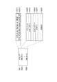
図1は、この発明の一実施の形態に係るデータ構造を説明する図である。ディスク状情報記録媒体100(図1(a))としては、DVD−RAM、DVD−RW、DVD−R等の記録可能光ディスクや、ハードディスク等の記録可能磁気ディスクがある。以下では、例えば405nm〜650nmのレーザを用いたDVD−RAM等の光ディスクを例にとって説明を続ける。 FIG. 1 is a diagram for explaining a data structure according to an embodiment of the present invention. Examples of the disk-shaped information recording medium 100 (FIG. 1A) include recordable optical disks such as DVD-RAM, DVD-RW, and DVD-R, and recordable magnetic disks such as a hard disk. In the following, description will be continued by taking an optical disc such as a DVD-RAM using a laser of 405 nm to 650 nm as an example.
ディスク100は、その内周側から外周側に向かって、リードイン領域110、ボリューム/ファイル構造情報領域111、データ領域112、およびリードアウト領域113を持っている(図1(b))。ボリューム/ファイル構造情報領域111内にはファイルシステムが格納されている。ファイルシステムは、どのファイルがどこに記録されているかを示す情報で構成されている(図3を参照して後述する)。記録コンテンツはデータ領域112に格納される(図1(c))。
The
データ領域112は、一般のコンピュータデータが記録される領域120と、AVデータを記録する領域121に分けられる。AVデータ記録領域121は、AVデータの管理をするためのファイル(VMGファイル)があるAVデータ管理情報領域130と、ビデオレコーディング規格のオブジェクトデータ(VOBS)ファイル(VROファイル)が記録されるVRオブジェクト群記録領域122と、デジタル放送に対応したストリームオブジェクト(SOBS:Stream OBject Set)が記録されるStreamオブジェクト群記録領域131で構成されている(図1(d))。つまり、この実施の形態では、デジタル放送のストリームオブジェクトは、VRオブジェクトとは別のファイルであるストリームオブジェクト132(SOBS)として記録される(図1(e))。
The
各ストリームオブジェクト132は、ディスク100へのアクセス単位となるデータユニット(SOBU:Stream OBject Unit)134が1つ以上集まって構成される(図1(f))。ここで、1つのSOBUは、オブジェクト管理情報内の値で指定された一定時間間隔のピクチャ単位で区切られたデータユニットである。あるいは、1つのSOBUは、1以上のGOPで区切られたデータユニットとしてもよい。各データユニット(SOBU)134は、複数TSパケットの集まりで構成されるパケットグループ(Packet Group)140が1つ以上集まって構成される(図1(g))。
Each
この実施の形態では、各パケットループ140は、例えば16個のパック(または16個のLB(Logical Block))の集まりで構成される。1個のパックサイズ(あるいは1個のLBサイズ)が2kバイトとすると、各パケットグループ140のサイズは32kバイトとなる。これはビデオレコーディング規格におけるECCブロックサイズと同じになる。
In this embodiment, each
各パケットグループ140は、ストリームレコーディング(SR)におけるパケット記録領域(DVD−TSパケット記録領域)160を構成している(図1(h))。このDVD−TSパケット記録領域160は、パケットグループヘッダ161と、複数ペア(例えば170ペア)のパケット到着時間情報(PAT)163およびMPEG−TSパケット162で構成することができる(図1(i))。このパケットグループ140の内容については、図33を参照して後に詳述する。
Each
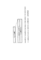
図2は、この発明の一実施の形態に係るデータ構造における再生管理情報層とオブジェクト管理情報層とオブジェクト層との関係を説明する図である。図1のAVデータ管理情報記録領域130に記録される管理情報(VMGファイル)は、ビデオレコーディング規格に基づく記録コンテンツおよびこの発明に基づくストリーム記録コンテンツの双方の再生手順を管理する再生管理情報層10を持っている。すなわち、ストリーム記録されたオブジェクトの再生単位であるセル13が1以上集まってプログラム12が構成され、ビデオレコーディング記録されたオブジェクトの再生単位であるセル13が1以上集まってプログラム12が構成され、これらのプログラム12の並び(再生手順)が、プログラムチェーン(PGC)11の管理情報(PGCI)で管理される。
FIG. 2 is a diagram for explaining the relationship among the reproduction management information layer, the object management information layer, and the object layer in the data structure according to the embodiment of the present invention. The management information (VMG file) recorded in the AV data management
ここでは、ストリーム記録側のセル13の途中から再生を開始する場合でも、ビデオレコーディング側のセル13の途中から再生を開始する場合でも、ユーザは再生時間(PTS)で再生場所を指定することができるようになっている。すなわち、ストリーム記録側のセル13の途中から再生時間(PTS)で再生を開始する場合では、ストリームオブジェクト管理情報層20内のストリームオブジェクト情報SOBI21を介してストリームオブジェクト層30内のストリームオブジェクトSOB132を指定し、ストリームオブジェクト管理情報層20内のストリームオブジェクトユニット情報SOBUI22を介してストリームオブジェクト層30内のストリームオブジェクトユニットSOBU134を指定する。SOB132およびそのSOBU134が指定されると、再生開始場所が特定される。(ここでのSOBUIはグローバル情報22と言い換えてもよい。)
このSOBU134は、1以上のパケットグループ140により構成される。SOBU134は、例えば1以上のGOPに対応するデータ単位である。あるいは、オブジェクト管理情報内の値で指定された一定の再生時間分のデータ量に相当する単位でSOBU134を区切ってもよい。これにより、各情報フィールドのオーバーフローが防止される。
Here, even when playback is started from the middle of the
The
各パケットグループ140は、16個のパック(あるいは16個のLB)(32768バイト)で構成され、先頭にパケットグループヘッダ161を持ち、その後に、複数ペア(この例では170ペア)のPAT163およびTSパケット162が配置される。これらのTSパケット162内にストリームレコーディングの記録コンテンツが格納される。
Each
一方、ビデオレコーディング側のセル13の途中から再生時間(PTS)で再生を開始する場合では、ビデオオブジェクト(VOB)管理情報層23内のビデオオブジェクト情報VOBI24を介してビデオオブジェクト層35内のビデオオブジェクトVOB36を指定し、ビデオオブジェクト管理情報層23内のビデオオブジェクトユニット情報VOBUI25を介してビデオオブジェクト層35内のビデオオブジェクトユニットVOBU37を指定する。VOB36およびそのVOBU37が指定されると、再生開始場所が特定される。VOBU37は複数パック38により構成され、これらのパック内にビデオレコーディングの記録コンテンツが格納される。
On the other hand, when playback is started from the middle of the
ストリーム記録側のセル13の途中から再生を開始する場合では、SOBU_PB_TM(図22)により、フィールド数単位の時間で、再生開始場所を指定できるようになっている。また、ビデオレコーディング側のセル13の途中から再生を開始する場合では、ビデオレコーディング規格で規定されているタイムマップ情報(TMAPI)内のVOBU_PB_TM(図24)により、再生開始場所を指定できるようになっている。
In the case of starting playback from the middle of the
図2の示すところを纏めると、次のようになる。すなわち、SOBS(Stream Object Set)の構造は、1以上のSOB(Stream OBject)で構成される。このSOBは、例えば一番組に相当する。SOBは1以上のSOBU(Stream OBject Unit)で構成され、このSOBUは、一定時間間隔(図18/図17のVOBU/SOBU_PBT_RNG;VOBU/SOBU PlayBack Time Rangeの値により変化する)分のオブジェクトデータ、もしくは1以上のGOPデータに相当する。 2 can be summarized as follows. That is, the structure of SOBS (Stream Object Set) is composed of one or more SOBs (Stream OBject). This SOB corresponds to, for example, one program. The SOB is composed of one or more SOBUs (Stream Object Units), and this SOBU has object data for a fixed time interval (VOBU / SOBU_PBT_RNG in FIG. 18 / FIG. 17; changes depending on the value of VOBU / SOBU PlayBack Time Range) Or it corresponds to one or more GOP data.
ただし、転送レートが低い場合、1秒(1s)以内で1GOPが送られない場合が考えられる(アナログビデオ入力を装置内部でMPEGエンコードするDVD−VRでは、内部エンコードであるためデータユニットの構成を自由に設定できるが、デジタル放送の場合ではエンコードが放送局側にあるため、どんなデータがくるか不明な可能性がある)。また、伝送レートが高く、Iピクチャが頻繁に送られる場合なども考えられる。その場合、SOBUが頻繁に区切られ、それに伴いSOBUの管理情報が増え、全体の管理情報が肥大化する恐れがある。そこで、この発明の一実施の形態に係るSOBUは、一定時間間隔(最小の制限は、SOB最後のSOBU以外、区切りがピクチャ単位となること)または1以上GOPで区切るのが適当となる。 However, when the transfer rate is low, 1 GOP may not be sent within 1 second (1 s) (in DVD-VR which MPEG encodes analog video input inside the device, since it is internal encoding, the configuration of the data unit is It can be set freely, but in the case of digital broadcasting, since the encoding is on the broadcasting station side, there is a possibility that it is unclear what kind of data will come). In addition, there may be a case where the transmission rate is high and I pictures are frequently sent. In that case, SOBUs are frequently divided, and accordingly, SOBU management information increases, and the overall management information may be enlarged. Therefore, it is appropriate to divide the SOBU according to the embodiment of the present invention by a fixed time interval (the minimum limit is that the delimiter is a picture unit other than the SOBU last SOBU) or one or more GOPs.
1つのSOBUは1以上のパケットグループで構成され、各パケットグループは、基本的には、16個のpack(1Pack=1セクタ:2048バイトサイズ)で構成される。また、パケットグループはパケットグループヘッダとTSパケット(170個)で構成されている。各TSパケットの到着時間は、各TSパケット162とペアとなるPAT163から分かるようになっている。
One SOBU is composed of one or more packet groups, and each packet group is basically composed of 16 packs (1 Pack = 1 sector: 2048 byte size). The packet group includes a packet group header and TS packets (170 packets). The arrival time of each TS packet can be known from the
次に、図3〜図32を参照しながら、管理情報について説明する。図3は、この発明の一実施の形態に係るファイル構造を説明する図である。図1のディスク100内のデータは、ファイルシステムが入っているボリューム/ファイル構造情報領域111と、データファイルを実際に記録するデータ領域112で構成されている。ボリューム/ファイル構造情報領域111に格納されるファイルシステムは、図3に示すように、どのファイルがどこに記録されているかを示す情報で構成されている。また、データ領域112には一般のコンピュータが記録する領域120とAVデータを記録する領域121に分けられている。AVデータ記録領域121は、記録されたAVデータを管理するためのHDVMGファイル(およびそのバックアップファイル)があるAVデータ管理情報領域130と、ビデオレコーディング規格のオブジェクトデータ(VOBS)ファイル(VROファイル)の記録されるVRオブジェクト群記録領域122と、デジタル放送に対応したオブジェクト(SOBS)が記録されているStreamオブジェクト群記録領域131で構成されている。
Next, management information will be described with reference to FIGS. FIG. 3 is a view for explaining the file structure according to the embodiment of the present invention. The data in the
ここで、DVD−Video(ROM Video)はVIDEO−TS、DVD−RTR(録再DVD)はDVD−RTAVと、フォーマット毎にディレクトリを分けており、今回のデジタル放送対応DVD規格も例えばDVD_HDVRというディレクトリに記録される。 Here, DVD-Video (ROM Video) is divided into VIDEO-TS, DVD-RTR (recording / playback DVD) is divided into DVD-RTAV, and the directory for each format is divided. To be recorded.
つまり、図3に示すように、DVD_HDVRというディレクトリには、データの管理を行うためのVMGファイル(HR_MANGER.IFOおよびそのバックアップ用HR_MANGER.BUP)と、アナログ放送及びアナログライン入力などのアナログAV情報記録用のオブジェクトファイルであるVROファイル(HR_MOVIEO.VRO)と、デジタル放送のオブジェクトであるSROファイル(HR_STRMx.SRO;x=0,1,2,…)と、スチルオブジェクト用ファイル(HR_STILL.VRO)と、オーディオオブジェクト用ファイル(HR_AUDIO.VRO)とが記録される。ここで、SROファイルの対象はSOBSとされる。 In other words, as shown in FIG. 3, in a directory called DVD_HDVR, a VMG file (HR_MANGER.IFO and its backup HR_MANGER.BUP) for managing data, and analog AV information recording such as analog broadcasting and analog line input are recorded. VRO file (HR_MOVIE.VRO), an object file for digital broadcasting, an SRO file (HR_STRMx.SRO; x = 0, 1, 2,...), An object for digital broadcasting, and a still object file (HR_STILL.VRO) The audio object file (HR_AUDIO.VRO) is recorded. Here, the target of the SRO file is SOBS.
図3では、さらに、例1としてのタイムマップファイル(HR_TMAP.IFO)およびそのバックアップファイル(HR_TMAP.BUP)が、独立したファイルとして設けられている。これらのファイル(HR_TMAP.IFOとHR_TMAP.BUP)には、タイムマップテーブルTMAPTの情報を格納することができるようになっている(つまりTMAPTは他の管理情報とは別にファイル管理できる)。 In FIG. 3, the time map file (HR_TMAP.IFO) and the backup file (HR_TMAP.BUP) as Example 1 are further provided as independent files. In these files (HR_TMAP.IFO and HR_TMAP.BUP), information of the time map table TMAPT can be stored (that is, TMAPT can be managed separately from other management information).
そして、図3に示されるようにSRの管理データはVRと共通のHDVMGファイルに記録されてVRと共通に制御され、図2に示されるようにSRの管理データとVRの管理データはCELL単位でリンクされ、再生場所の指定は再生時間単位で指定される。 As shown in FIG. 3, the SR management data is recorded in the HDVMG file common to the VR and controlled in common with the VR, and the SR management data and the VR management data are in CELL units as shown in FIG. The playback location is specified in units of playback time.
なお、DVD_HDVRディレクトリには、図示しないが、チャプタメニューなどに利用できるサムネール(縮小画像)用のファイルとして、HR_THNL.DATを設けることができる。さらに、図示しないが、アイテムテキスト(IT_TXT)とは別の追加テキストファイル:HR_TEXT.DATや、エントリポイント(EP)に追加された情報を保存するためのHR_EXEP.DATを、適宜、DVD_HDVRディレクトリに設けることも可能である。 Although not shown, the DVD_HDVR directory contains HR_THNL. As a thumbnail (reduced image) file that can be used for a chapter menu or the like. DAT can be provided. Further, although not shown, an additional text file different from the item text (IT_TXT): HR_TEXT. DAT and HR_EXEP. For storing information added to the entry point (EP). DAT can be provided in the DVD_HDVR directory as appropriate.
なお、図3に示すようにTMAPTを別ファイルにする代わりに、例2としてのTMAPTを、図4に示すようにHDVR_VMGの末尾に追加する方法も可能である。 Instead of using TMAPT as a separate file as shown in FIG. 3, it is also possible to add TMAPT as Example 2 to the end of HDVR_VMG as shown in FIG.
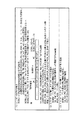
図4は、AVデータ管理情報記録領域130に記録される管理情報の1つ(HDVR_VMG)の一部(HDVR_VMGI)がどのように構成されるかの一例を説明する図である。この実施の形態におけるストリームレコーディングをSR(Stream Recording)と略記し、ビデオレコーディングをVR(Video Recording)と略記する。すると、SRデータの管理情報(STR_FIT;Stream File Information Table)は、HDVR_VMG130内(図3のHR_MANGER.IFO内)に保存され、VRデータと同列に管理される。
FIG. 4 is a diagram for explaining an example of how a part (HDVR_VMGI) of one piece of management information (HDVR_VMG) recorded in the AV data management
HDVR_VMG130は、ビデオマネージャ情報(HDVR_VMGI)1310と、ストリームファイル情報テーブル(STR_FIT)1320と、(オリジナルの)プログラムチェーン情報1330と、プレイリスト情報1340と、テキストデータマネージャ1350と、業者情報テーブル1360と、タイムマップテーブルTMAPT(例2)1370を含んで構成されている。
ここで、TMAPT1370の位置がVMG130の末尾であることには重要な意味がある。すなわち、TMAPT1370の位置がVMG130の末尾にあるので、TMAPが頻繁に書き替えられそのデータサイズが増減しても、その都度VMGI・1310〜MNFIT1360を書き替える必要は無くなる。
Here, it is important that the position of
別の言い方をすると、DVDレコーダでは、通常、VOBの管理情報として、タイムマップ情報(TMAPI)を持っている。この情報はオブジェクトデータ(VOB/SOB)をデータユニット(VOBU/SOBU)毎に分けて、その単位で再生、特殊再生等を行えるようにするための情報であるが、最大0.5s毎に1件の情報が必要になる。このため、将来、ディスクの容量が増えたり、圧縮効率の高い圧縮方式を採用した場合、タイムマップ情報TMAPIが増え、編集などを行った場合に煩雑になる。このTMAPIが管理情報ファイル(図3のHR_MANGER.IFO)内にあるとTMAPIを変更するだけで、関係のない他の領域の管理データを移動しあるいは書き換えする等の必要がでてきて、効率が悪い。 In other words, a DVD recorder usually has time map information (TMAPI) as VOB management information. This information is information for dividing the object data (VOB / SOB) into data units (VOBU / SOBU) so that playback, special playback, etc. can be performed in that unit. Information is required. For this reason, in the future, when the capacity of the disk increases or a compression method with high compression efficiency is adopted, the time map information TMAPI increases, and it becomes complicated when editing or the like is performed. If this TMAPI is in the management information file (HR_MANGER.IFO in FIG. 3), it is necessary to move or rewrite management data in other unrelated areas simply by changing the TMAPI. bad.
そこで、この発明の一実施の形態では、その状況を改善するために、TMAPIを別領域(図3のHR_TMAP.IFOあるいは図4のHDVR_VMGの末尾に配置されたTMAPTなど)に記録するようにして対応している。 Therefore, in one embodiment of the present invention, in order to improve the situation, TMAPI is recorded in another area (HR_TMAP.IFO in FIG. 3 or TMAPT arranged at the end of HDVR_VMG in FIG. 4). It corresponds.
図4において、HDVR_VMGI・1310は、ディスク管理識別情報(VMG_ID)1311と、バージョン情報(VERN)1312と、例1としてのプロファイル情報1313と、TMAPTの更新日時が記述されるIFO_LAST_MOD_TMと、ストリームオブジェクト管理情報開始アドレス1314と、プログラムチェーン情報開始アドレス1315と、プレイリスト情報開始アドレス1316を含んで構成されている。SRストリームの管理情報は、STR_FIT1320に保存される。
In FIG. 4,
図4の例において、VMGI内にTMAPTの更新日時情報(IFO_LAST_MOD_TM)を記載し、この値とTMAPTファイルに記載されている更新日時情報(図示せず)を比較し、同じ値であれば整合性が取れているものとして処理を行うことができる。 In the example of FIG. 4, TMAPT update date / time information (IFO_LAST_MOD_TM) is described in VMGI, and this value is compared with update date / time information (not shown) described in the TMAPT file. The processing can be performed assuming that
図4のVMGI・1310に含まれるプロファイル情報(例1)1313は、図5および図45を参照して後述するが、種々なデコード機能のサポート状況を示すために用いることができる。
The profile information (example 1) 1313 included in the
図5は、図4のプロファイル情報(例1)の具体例を説明する図である。この例1のプロファイル情報は、8ビットのオプションサポートフラグと16ビットのリージョン番号で構成されている。このリージョン番号は、00で日本(ARIB)、01で米国(ATSC)、02で欧州(DVB)、0xffffで世界共通と示される。これにより、録画されたコンテンツは、リージョン番号に対応した地域のデータが再生可能となる。 FIG. 5 is a diagram illustrating a specific example of the profile information (example 1) in FIG. The profile information of Example 1 is composed of an 8-bit option support flag and a 16-bit region number. This region number is indicated as 00 for Japan (ARIB), 01 for the United States (ATSC), 02 for Europe (DVB), and 0xffff as universal. As a result, the recorded content can reproduce the data of the region corresponding to the region number.
通常、DVDでは、登録されている圧縮フォーマットはすべて再生必須という原則があり、これにより、各社のDVDレコーダの互換を取っている。しかしながら、次世代のDVDでは、複数の種類のビデオフォーマットが登録になり、そのため、全フォーマット再生必須を貫くと全ての機器が非常に価格の高いDVDレコーダになる。 Normally, a DVD has a principle that all registered compression formats are required to be played back, so that DVD recorders of various companies are compatible. However, in the next-generation DVD, a plurality of types of video formats are registered. Therefore, if all formats are required to be reproduced, all devices become very expensive DVD recorders.
この価格高騰問題を改善するために、フォーマット対応機能をBASEと複数のオプションにわけ、目的別、価格帯によりサポートするオプションを使い分ける。この場合、サポートしていないオプションのデータが来たときに自分のサポート状況とストリームの状況を比べられるように、コンテンツにその情報を入れて対応することになる。この発明の一実施の形態では、このような状況でVMGI内にそのオプション状況(図5のオプションサポートフラグ)を入れることにより、複数のオプションのバリエーションに対応したDVDレコーダを提供可能としている(詳細は図45を参照して後述する)。 In order to improve the price increase problem, the format support function is divided into BASE and a plurality of options, and the options supported by the purpose and price range are used properly. In this case, when the optional data that is not supported comes, the information is included in the content so that the support status can be compared with the status of the stream. In one embodiment of the present invention, by inserting the option status (option support flag in FIG. 5) in VMGI in such a situation, it is possible to provide a DVD recorder corresponding to a plurality of option variations (details). Will be described later with reference to FIG. 45).
ところで、デジタル放送は国毎に放送方式が違い、ヨーロッパではDVB、米国ではATSC、日本ではARIBとなっている。[1]DVBでは、ビデオはMPEG2であるが解像度が1152*1440i、1080*1920(i、p)、1035*1920、720*1280、(576、480)*(720、544、480、352)、(288、240)*352でフレーム周波数は30Hz、25Hzとなり、オーディオはMPEG-1 audio、MPEG-2 Audioでサンプリング周波数が32kHz、44.1kHz、48kHzとなっている。[2]ATSCでは、ビデオはMPEG2であるが解像度は1080*1920(i、p)、720*1280p、480*704(i、p)、480*640(i、p)でフレーム周波数は23.976Hz、24Hz、29.97Hz、30Hz、59.94Hz、60Hzとなり、オーディオはMPEG1 Audio Layer 1 & 2(DirecTV)、AC3 Layer 1 & 2(Primstar)でサンプリング周波数は48kHz、44.1kHz、32kHzとなっている。[3]ARIBでは、ビデオはMPEG2であり、解像度は1080i、720p、480i、480pでフレームレートは29.97Hz、59.94Hzとなり、オーディオはAAC(MPEG-2 Advanced Audio Coding)でサンプリング周波数が48kHz、44.1kHz、32kHz、24kHz、22.05kHz、16kHzとなっている。 By the way, digital broadcasting has a different broadcasting system for each country, DVB in Europe, ATSC in the United States, and ARIB in Japan. [1] In DVB, the video is MPEG2, but the resolution is 1152 * 1440i, 1080 * 1920 (i, p), 1035 * 1920, 720 * 1280, (576, 480) * (720, 544, 480, 352) , (288, 240) * 352, the frame frequency is 30Hz and 25Hz, and the audio is MPEG-1 audio and MPEG-2 Audio, and the sampling frequency is 32kHz, 44.1kHz and 48kHz. [2] In ATSC, the video is MPEG2, but the resolution is 1080 * 1920 (i, p), 720 * 1280p, 480 * 704 (i, p), 480 * 640 (i, p), and the frame frequency is 23.976Hz , 24Hz, 29.97Hz, 30Hz, 59.94Hz, 60Hz, audio is MPEG1 Audio Layer 1 & 2 (DirecTV), AC3 Layer 1 & 2 (Primstar), sampling frequency is 48kHz, 44.1kHz, 32kHz. [3] In ARIB, the video is MPEG2, the resolution is 1080i, 720p, 480i, 480p, the frame rates are 29.97Hz, 59.94Hz, the audio is AAC (MPEG-2 Advanced Audio Coding), the sampling frequency is 48kHz, 44.1 It is kHz, 32kHz, 24kHz, 22.05kHz, 16kHz.
このことから、使用する地域によりレコーダに実装するデコーダが異なるために、レコーダで記録したディスクに何をサポートしたレコーダを使用しているかを示す情報(図5のリージョンコード)をVMGIに保存し、なにをサポートしたレコーダでディスクに書き込んだかを示すようにしている。 For this reason, since the decoder mounted on the recorder differs depending on the region to be used, information (region code in FIG. 5) indicating what supported recorder is used for the disk recorded by the recorder is stored in the VMGI, It shows what is written on the disc with a recorder that supports it.
図6は、この発明の一実施の形態に係るデータ構造において、管理情報の1つ(HDVR_VMG)の他部(M_AVFITとSTR_FIT)がどのように構成されるかの一例を説明する図である。VRデータ管理情報およびSRストリーム管理情報はHDVR_VMG内に保存され、これによりストリームデータはVRデータと同列に管理される。すなわち、VRデータ管理情報はM_AVFIT(Movie AV File Information Table)に保存され、M_AVFITはVOB毎にVOBI(Video Object Information)内にMVOB_TMAPI(Movie Video Object Timemap Information)を含んでいる。また、ストリームの管理情報はSTR_FIT(Stream File Information Table)に保存され、STR_FITはSTR_FITI(STR_FITInformation)と1以上のSTR_FI(Stream File Information)で構成されている。そして、各STR_FIが、MVOB_TMAPIに対応した機能を持つSOB_TMAPIを、そのデータ階層の中に含んでいる(図8を参照して後述する)。 FIG. 6 is a diagram for explaining an example of how the other part (M_AVFIT and STR_FIT) of one management information (HDVR_VMG) is configured in the data structure according to the embodiment of the present invention. The VR data management information and the SR stream management information are stored in HDVR_VMG, whereby the stream data is managed in the same row as the VR data. That is, VR data management information is stored in M_AVFIT (Movie AV File Information Table), and M_AVFIT includes MVOB_TMAPI (Movie Video Object Timemap Information) in VOBI (Video Object Information) for each VOB. Further, stream management information is stored in a STR_FIT (Stream File Information Table), and the STR_FIT includes STR_FITI (STR_FITInformation) and one or more STR_FI (Stream File Information). Each STR_FI includes SOB_TMAPI having a function corresponding to MVOB_TMAPI in its data hierarchy (described later with reference to FIG. 8).
図7は、図6のSTR_FITIおよびSTR_FIがどのように構成されるかの一例を説明する図である。すなわち、STR_FITIは、STR_FIの総数(STR_FI_Ns)と、このテーブル(STR_FIT)の終了アドレス(STR_FIT_EA)で構成されている。また、STR_FIは、STR_FI_GI(STR_FI General Information)、1以上のSOBI_SRP(Stream Object Information Search Pointer)、およびこのSOBI_SRP#と同じ番号数値(#1〜#K)で示されるSOBI(SOB Information)で構成されている。 FIG. 7 is a diagram for explaining an example of how STR_FITI and STR_FI in FIG. 6 are configured. That is, STR_FITI is configured by the total number of STR_FI (STR_FI_Ns) and the end address (STR_FIT_EA) of this table (STR_FIT). STR_FI is composed of STR_FI_GI (STR_FI General Information), one or more SOBI_SRP (Stream Object Information Search Pointer), and SOBI (SOB Information) indicated by the same numerical value (# 1 to #K) as this SOBI_SRP #. ing.
図8は、図7のSTR_FI_GIおよびSOBIがどのように構成されるかの一例を説明する図である。STR_FI_GIは、ファイル名(FILE_NAME)およびSOBIサーチポインタ数(SOBI_SRP_Ns)で構成されている。また、対応する#番号のSOBI_SRP#で示されるSOBI#は、SOBI_GI(SOBI General Information)と、1以上のSOB_ESI(SOB Elementary Stream Information)#と、SOB_SMLI(SOB Seamless Information)と、SOB_AGAPI(SOB Audio GAP Information)と、SOB_TMAPI(SOB Time Map Information)と、SOB_ES_GPI(SOB Elementary Stream Group Information)で構成されている。ここで、SOB_ESIはさらに、SOB_V_ESI(SOB Video ESI)と、SOB_A_ESI(SOB Audio ESI)を含んで構成されている(図9参照)。 FIG. 8 is a diagram illustrating an example of how STR_FI_GI and SOBI in FIG. 7 are configured. STR_FI_GI includes a file name (FILE_NAME) and the number of SOBI search pointers (SOBI_SRP_Ns). The SOBI # indicated by the SOBI_SRP # of the corresponding # number includes SOBI_GI (SOBI General Information), one or more SOB_ESI (SOB Elementary Stream Information) #, SOB_SMLI (SOB Seamless Information), and SOB_AGAPI (SOB Audio GAP). Information), SOB_TMAPI (SOB Time Map Information), and SOB_ES_GPI (SOB Elementary Stream Group Information). Here, SOB_ESI further includes SOB_V_ESI (SOB Video ESI) and SOB_A_ESI (SOB Audio ESI) (see FIG. 9).
図9は、図8のSOBIに含まれるSOBI_GIがどのように構成されるかの一例を説明する図である。図9に示すように、SOBI_GIは、SOB_TY(SOB形式)と、PKT_TY(パケット形式)と、PKT_SZ(パケットサイズ)と、PKT_GRP_SZ(パケットグループサイズ)と、PKT_Ns(パケット数)と、COUNTRY_CODE(国コード)と、AP_FORMAT(アプリケーションフォーマット)を含んでいる。 FIG. 9 is a diagram illustrating an example of how the SOBI_GI included in the SOBI of FIG. 8 is configured. As shown in FIG. 9, SOBI_GI includes SOB_TY (SOB format), PKT_TY (packet format), PKT_SZ (packet size), PKT_GRP_SZ (packet group size), PKT_Ns (number of packets), and COUNTRY_CODE (country code). ) And AP_FORMAT (application format).
SOBI_GIはさらに、SERVICE_ID(サービスID)と、SERVICE_TYPE(サービス形式)と、PMT_PID(PMTのパケットID)と、NETWORK_ID(ネットワークID)と、TS_ID(トランスポートストリームID)と、PCR_PID(PCRのパケットID)と、SOB_DEF_PID(SOBのデフォルトPID)を含んでいる。 SOBI_GI further includes SERVICE_ID (service ID), SERVICE_TYPE (service format), PMT_PID (PMT packet ID), NETWORK_ID (network ID), TS_ID (transport stream ID), and PCR_PID (PCR packet ID). And SOB_DEF_PID (the default PID of SOB).
SOBI_GIはさらに、Format_ID(フォーマットID)と、CP_CTRL_INFO(コピー制御情報)と、SOB_REC_TM(SOB記録時間)と、SOB_REC_TM_SUB(SOB記録サブ時間)と、SOB_DURATION(SOB期間)と、SOB_S_PTM(SOB開始時間)と、SOB_E_PTM(SOB終了時間)を含んでいる。 SOBI_GI further includes Format_ID (format ID), CP_CTRL_INFO (copy control information), SOB_REC_TM (SOB recording time), SOB_REC_TM_SUB (SOB recording sub time), SOB_DURATION (SOB period), SOB_S_PTM (SOB_S_PTM) , SOB_E_PTM (SOB end time).
SOBI_GIはさらに、LOCAL_TM_ZONE(ローカルタイムゾーン)と、PCR_POS_COUNT(PCR位置カウント)と、PCR_POS_SHIFT(PCR位置シフト)と、SOB_ES_Ns(SOBのES数)と、SOB_V_ES_Ns(SOBのビデオES数)と、SOB_A_ES_Ns(SOBのオーディオES数)と、末尾にプロファイル情報(例2)を含んでいる。 SOBI_GI further includes LOCAL_TM_ZONE (local time zone), PCR_POS_COUNT (PCR position count), PCR_POS_SHIFT (PCR position shift), SOB_ES_Ns (number of SOB ES), SOB_V_ES_Ns (number of SOB video ES), SOB_A_ES_B Audio ES number) and profile information (example 2) at the end.
図9の例では、ディスク毎に図5のプロファイル情報を持つ(例1)代わりに、各ディスク内のSOB毎にプロファイル情報を持つ(例2)場合を示している。 In the example of FIG. 9, a case is shown in which profile information is provided for each SOB in each disk (example 2) instead of the profile information of FIG. 5 for each disk (example 1).
図10は、図9のSOBI_GIに含まれる種々な情報を説明する図である。SOB_TYは、そのビットb15が0のときは通常のSOBであることが示され、ビットb15が1のときは仮消去状態のSOBであることが示され、ビットb14が0のときはGPIが無いことが示され、ビットb14が1のときはGPIが有ることが示される。PKT_TYは、その内容が01であれば(パケットに含まれるストリームが)MPEG−TSであることが示され、0xffであれば(パケットに含まれるストリームが)認識不能あるいは解析不能(Non-cognizant)であることが示される。PKT_SZが00Bchであればパケットサイズが188バイトであることが示される。 FIG. 10 is a diagram for explaining various types of information included in SOBI_GI in FIG. SOB_TY indicates that it is a normal SOB when bit b15 is 0, indicates that it is a temporarily erased SOB when bit b15 is 1, and there is no GPI when bit b14 is 0 When bit b14 is 1, it indicates that GPI is present. PKT_TY indicates that the content is 01 (the stream included in the packet) is MPEG-TS, and if 0xff (the stream included in the packet) is unrecognizable or not parsed (Non-cognizant) It is shown that. If PKT_SZ is 00Bch, it indicates that the packet size is 188 bytes.
PKT_GRP_SZはパケットグループのサイズがどのくらいか(8論理ブロックサイズか16論理ブロックサイズか等)を示す。図1(g)の例示によれば、PKT_GRP_SZ=16Logical Blockで固定となる。PKT_Nsは1つのパケットグループ内のパケット数(例えば0xAA:170 TS packetで固定)を示す。COUNTRY_CODEは録画を行った装置(DVDレコーダ等)が販売または頒布される国のコード(例えばJPN=日本)を示す。AP_FORMATは、その内容が1であればISDB−S(BS/CS放送)であることが示され、2であればISDB−T(地上デジタル放送)であることが示される。 PKT_GRP_SZ indicates how large the packet group is (8 logical block size or 16 logical block size, etc.). According to the example of FIG. 1G, PKT_GRP_SZ = 16 Logical Block is fixed. PKT_Ns indicates the number of packets in one packet group (for example, 0xAA: fixed at 170 TS packets). COUNTRY_CODE indicates a code (for example, JPN = Japan) of a country where a recording apparatus (DVD recorder or the like) is sold or distributed. If the content of AP_FORMAT is 1, it indicates that it is ISDB-S (BS / CS broadcast), and if it is 2, it indicates that it is ISDB-T (digital terrestrial broadcast).
さらに、PSI、SI値を元に、SERVICE_ID、PMT_ID、NETWORK_ID、TS_ID、FORMAT_IDが構成され;録画するデータを元に、SOB_ES_Ns(録画のために選択したESの数)、SOB_V_ES_Ns(録画したビデオESのうちTMAPを作ったESの数)、SOB_A_ES_Ns(録画したオーディオESのうちTMAPを作ったESの数)が構成される。 Furthermore, SERVICE_ID, PMT_ID, NETWORK_ID, TS_ID, and FORMAT_ID are configured based on the PSI and SI values; SOB_ES_Ns (the number of ESs selected for recording), SOB_V_ES_Ns (the number of recorded video ESs) based on the data to be recorded Of these, the number of ESs that made TMAP) and SOB_A_ES_Ns (the number of ESs that made TMAP among recorded audio ESs) are configured.
ここで、SOB_ES_NsとSOB_V_ES_NsとSOB_A_ES_NsとES_TMAP_Ns(図17参照)は、以下の式で示される関係を持っている:
SOB_ES_Ns ≧ SOB_V_ES_Ns + SOB_A_ES_Ns
SOB_V_ES_Ns + SOB_A_ES_Ns ≧ ES_TMAP_Ns
また、PCR_POS_COUNTによりパケットグループの先頭から何個前のPCRを参照するのかが示され、PCR_POS_SHIFTによりPCRパケットの位置を示すLBの2の指数部分が示され、CP_CTRL_INFOにより著作権保護等のためのコピー制御が行われる。
Here, SOB_ES_Ns, SOB_V_ES_Ns, SOB_A_ES_Ns, and ES_TMAP_Ns (see FIG. 17) have a relationship represented by the following formula:
SOB_ES_Ns ≧ SOB_V_ES_Ns + SOB_A_ES_Ns
SOB_V_ES_Ns + SOB_A_ES_Ns ≥ ES_TMAP_Ns
Also, PCR_POS_COUNT indicates how many previous PCRs are to be referred to from the beginning of the packet group, PCR_POS_SHIFT indicates the
なお、デフォルトのPID(SOB_DEF_PID)は、ARIBの場合、コンポーネントタグの小さい値のものを指す(ただしコンポーネントグループ記述子の値が優先される)。SOB_DURATIONはSOBの再生時間を示すもので、SOBU_ENTの合計に対応する。 In the case of ARIB, the default PID (SOB_DEF_PID) indicates a value with a small component tag (however, the value of the component group descriptor is given priority). SOB_DURATION indicates the SOB playback time and corresponds to the sum of SOBU_ENT.
図11は、図8のSOBIに含まれるSOBI_GIがどのように構成されるかの他例を説明する図である。ここでは、SOBI_GIは、SOB_ES_PID(ESのPID)と、STREAM_TYPE(PMT内で示されるSTREAM type)と、STREAM_CONTENT(コンポーネント記述子で示されるSTREAM_CONTENTの値)と、COMPONENT_TYPE(コンポーネント記述子で示されるCOMPONENT_TYPEの値)と、COMPONENT_TAG(コンポーネント記述子で示されるCOMPONENT_TAGの値)と、CP_CTL_INFO(コピー制御情報/著作権管理情報)とで構成されている。 FIG. 11 is a diagram illustrating another example of how the SOBI_GI included in the SOBI of FIG. 8 is configured. Here, SOBI_GI includes SOB_ES_PID (ES PID), STREAM_TYPE (STREAM type indicated in PMT), STREAM_CONTENT (value of STREAM_CONTENT indicated by component descriptor), and COMPONENT_TYPE (COMPONENT_TYPE indicated by component descriptor). Value), COMPONENT_TAG (COMPONENT_TAG value indicated by the component descriptor), and CP_CTL_INFO (copy control information / copyright management information).
図12は、図8のSOBIに含まれるSOB_ESIがどのように構成されるかの一例を説明する図である。この例では、SOB_ESIは3種類(SOB_V_ESIと、SOB_A_ESIと、SOB_OTHER_ESI)に分けられている。 FIG. 12 is a diagram illustrating an example of how the SOB_ESI included in the SOBI of FIG. 8 is configured. In this example, SOB_ESI is divided into three types (SOB_V_ESI, SOB_A_ESI, and SOB_OTHER_ESI).
図13は、図12の各SOB_ESI(ここではSOB_ESI#m)に含まれるSOB_V_ESIがどのように構成されるかの一例と、このSOB_V_ESIに含まれるビデオ属性V_ATTRがどのように構成されるかの一例を説明する図である。 FIG. 13 shows an example of how the SOB_V_ESI included in each SOB_ESI (here SOB_ESI # m) in FIG. 12 is configured and an example of how the video attribute V_ATTR included in this SOB_V_ESI is configured. FIG.
SOB_V_ESIは、ESの形式を示すES_TYと、ESのPIDを示すES_PIDと、STREAM_TYPE(PMT内で示されるSTREAM type)と、COMPONENT_TAG(コンポーネント記述子で示されるCOMPONENT_TAGの値)と、COMPONENT_TYPE(コンポーネント記述子で示されるCOMPONENT_TYPEの値)と、ビデオの属性を示すV_ATTRと、CP_CTL_INFO(コピー制御情報/著作権管理情報)とで構成されている。 SOB_V_ESI includes ES_TYPE indicating the ES format, ES_PID indicating the ES PID, STREAM_TYPE (STREAM type indicated in the PMT), COMPONENT_TAG (COMPONENT_TAG value indicated by the component descriptor), and COMPONENT_TYPE (component descriptor). COMPONENT_TYPE value), V_ATTR indicating video attributes, and CP_CTL_INFO (copy control information / copyright management information).
V_ATTR(16ビット)は、ビデオのアスペクト比を指定するアプリケーションフラグ、水平解像度を示すデータ等を含んで構成されている。 V_ATTR (16 bits) includes an application flag that specifies an aspect ratio of video, data indicating horizontal resolution, and the like.
図14は、図12の各SOB_ESI(ここではSOB_ESI#m)に含まれるSOB_A_ESIがどのように構成されるかの一例と、このSOB_A_ESIに含まれるオーディオ属性AUDIO_ATTRがどのように構成されるかの一例を説明する図である。 FIG. 14 shows an example of how SOB_A_ESI included in each SOB_ESI (here SOB_ESI # m) in FIG. 12 is configured, and an example of how audio attribute AUDIO_ATTR included in SOB_A_ESI is configured. FIG.
SOB_A_ESIは、ESの形式を示すES_TYと、ESのPIDを示すES_PIDと、STREAM_TYPE(PMT内で示されるSTREAM type)と、COMPONENT_TAG(コンポーネント記述子で示されるCOMPONENT_TAGの値)と、STREAM_CONTENT(コンポーネント記述子で示されるSTREAM_CONTENTの値)と、COMPONENT_TYPE(コンポーネント記述子で示されるCOMPONENT_TYPEの値)と、SIMULCAST_GP_TAG(マルチ放送時、開始時のオーディオフレームのズレ値)と、AUDIO_ATTR(オーディオの属性値)と、LANG_CODE(第一音声の言語コード)と、LANG_CODE2(第二音声の言語コード)と、CP_CTL_INFO(コピー制御情報/著作権管理情報)とで構成されている。 SOB_A_ESI includes ES_TY indicating the ES format, ES_PID indicating the ES PID, STREAM_TYPE (STREAM type indicated in the PMT), COMPONENT_TAG (COMPONENT_TAG value indicated by the component descriptor), and STREAM_CONTENT (component descriptor). STREAM_CONTENT value), COMPONENT_TYPE (COMPONENT_TYPE value indicated by the component descriptor), SIMULCAST_GP_TAG (audio frame deviation value at the start of multi-broadcast), AUDIO_ATTR (audio attribute value), and LANG_CODE (Language code of the first voice), LANG_CODE2 (language code of the second voice), and CP_CTL_INFO (copy control information / copyright management information). It is made.
AUDIO_ATTRは、Multi_lng(1=DUAL mono、0=それ以外)と、Main_Comp(1=主音声、0=それ以外)と、Quality_Indicator(音質表示を示す)と、Sampling_Rate(011=24KHz、101=32KHz、111=48KHz)で構成されている。この値は、音声コンポーネント記述子の値より設定される。 AUDIO_ATTR includes Multi_lng (1 = DUAL mono, 0 = others), Main_Comp (1 = main audio, 0 = others), Quality_Indicator (indicating sound quality display), Sampling_Rate (011 = 24 KHz, 101 = 32 KHz, 111 = 48KHz). This value is set from the value of the audio component descriptor.
図15は、図12の各SOB_ESI(ここではSOB_ESI#m)に含まれるSOB_OTHER_ESIがどのように構成されるかの一例を説明する図である。 FIG. 15 is a diagram illustrating an example of how the SOB_OTHER_ESI included in each SOB_ESI (SOB_ESI # m in FIG. 12) of FIG. 12 is configured.
SOB_OTHER_ESIは、ES_TYと、ES_PIDと、STREAM_TYPEと、COMPONENT_TAGと、CP_CTL_INFOの他に、さらに、DAT_COMP_ID(データコンテンツ符号化識別子)およびAD_DAT_COMP_IFO(Additional data Component Information)を含んで構成されている。 SOB_OTHER_ESI includes ES_TYPE, ES_PID, STREAM_TYPE, COMPONENT_TAG, and CP_CTL_INFO, and further includes DAT_COMP_ID (data content encoding identifier) and AD_DAT_COMP_IFO (Additional data Component Information).
図16は、図15のSOB_OTHER_ESIに含まれるコピー制御情報(著作権保護情報)CP_CTL_INFOがどのように構成されるかの他例を説明する図である。CP_CTL_INFOは、SOBI_GIとSOB_V_ESI、SOB_A_ESIとPacket Group HeaderのCPIにある。SOBI_GIのCPIが全体のコピー制御を行い、ESIのCPIが各ESのコピー制御を行い、各Packet Groupのコピー制御はPacket Group HeaderのCPIで行なわれる。ただし、SOBI_GIのCPI値よりESIのCPIの方が優先され、さらに、Packet Group HeaderのCPIは最優先となっている。これらのCPI値は、デジタルコピー制御記述子、コンテント利用記述子等により設定される。 FIG. 16 is a diagram illustrating another example of how copy control information (copyright protection information) CP_CTL_INFO included in SOB_OTHER_ESI in FIG. 15 is configured. CP_CTL_INFO is in CPI of SOBI_GI and SOB_V_ESI, SOB_A_ESI and Packet Group Header. The SOBI_GI CPI controls the entire copy, the ESI CPI controls the copy of each ES, and the copy control of each Packet Group is performed by the CPI of the Packet Group Header. However, the EPI CPI has priority over the SOBI_GI CPI value, and the Packet Group Header CPI has the highest priority. These CPI values are set by a digital copy control descriptor, a content use descriptor, or the like.
その内容は、CCIまたはCGMS(0=コピー禁止;1=コピー無制限許可)と、APS(0=APS無し、1=APSタイプ1付加、2=APSタイプ2付加、3=APSタイプ3付加)と、EPN(0=コンテンツ保護(インターネット出力保護)、1=コンテンツ保護無し)と、ICT(0=:解像度制限あり、1=制限無し)と、Retention(1=無し、0=一時蓄積時間有効)と、Retention_State(0=制限無し、1=1週間、2=2日、3=1日、4=12時間、5=6時間、6=3時間、7=1.5時間)である。このうち、リテンションは、Retention=0でコピー禁止時に、Retention_Stateで示される時間だけ一時保存が許され、その時間が過ぎれば消去する必要が有る。
The contents are CCI or CGMS (0 = copy prohibited; 1 = copy unlimited permission), APS (0 = no APS, 1 =
図17は、図8のSOBIに含まれるSOB_TMAPIがどのように構成されるかの一例を説明する図である。SOB_TMAPIは、SOB_TMAPI_GIと、1以上のES_TMAPI#で構成されている。SOB_TMAPI_GIは、ADR_OFS(ファイル先頭からSOB先頭までのPacket Group番号(LBアドレス))と、SOBU_PB_TM_RNG(SOBUの再生時間の範囲:1=0.4s〜1.2s、2=1s〜2s、3=2s〜3s)と、SOB_S_PKT_POS(SOBの先頭のPacket group内での始まり:1≦SOB_S_PKT_POS≦170)と、SOB_E_PKT_POS(SOBの先頭のPacket group内での終わり:1≦SOB_E_PKT_POS≦170)と、ES_TMAP_Ns(ES_TMAPの数)で構成される。 FIG. 17 is a diagram illustrating an example of how the SOB_TMAPI included in the SOBI of FIG. 8 is configured. The SOB_TMAPI is composed of SOB_TMAPI_GI and one or more ES_TMAPI #. SOB_TMAPI_GI includes ADR_OFS (Packet Group number (LB address) from the file head to SOB head) and SOBU_PB_TM_RNG (SOBU playback time range: 1 = 0.4 s to 1.2 s, 2 = 1 s to 2 s, 3 = 2 s to 3 s ), SOB_S_PKT_POS (start in SOB first packet group: 1 ≦ SOB_S_PKT_POS ≦ 170), SOB_E_PKT_POS (end in SOB first packet group: 1 ≦ SOB_E_PKT_POS ≦ 170), number of ES_TMAP_Ns (ES ).
また、各ES_TMAPIは、ES_PID(本TMAPの対象ESのPID)と、ADR_OFS(SOBファイル先頭から本ESの先頭までの論理アドレス)と、ES_S_PTM(スタートPTM)と、ES_E_PTM(エンドPTM)と、ES_SOBU_ENT_Ns(SOBU_ENTの数)と、LAST_SOBU_E_PKT_POS(最後のSOBUのPacket Group内での位置)と、TMAP_N(本ESに属するTMAPT内のTMAPの番号:ただし、TMAPTがVRとSRそれぞれ別領域に記録されている場合や各TMAPTに順番に記録されている場合は、この番号は無くても良い)で構成される。 Each ES_TMAPI includes ES_PID (PID of the target ES of the TMAP), ADR_OFS (logical address from the beginning of the SOB file to the beginning of the ES), ES_S_PTM (start PTM), ES_E_PTM (end PTM), and ES_SOBU_ENT_Ns. (Number of SOBU_ENT), LAST_SOBU_E_PKT_POS (position of the last SOBU in the packet group), and TMAP_N (number of TMAP in TMAPT belonging to this ES: TMAPT is recorded in separate areas for VR and SR, respectively. In this case, the number may be omitted if it is recorded in order in each TMAPT).
なお、SOBU_PB_TM_RNGを適切に設定する事により録画時間が増えても、TMAPI情報が極端に大きくなることを防止可能となる。ただしその場合、各ENTRYの時間間隔が広がる為、2倍速再生等がスムーズにできない可能性は増える。 It is possible to prevent TMAPI information from becoming extremely large even if the recording time is increased by appropriately setting SOBU_PB_TM_RNG. However, in this case, since the time interval of each ENTRY is widened, there is an increased possibility that double-speed playback or the like cannot be performed smoothly.
図18は、図6のMVOB_TMAPに含まれるMVOB_TMAP_GIがどのように構成されるかの一例を説明する図である。MVOB_TMAP_GIは、VRのムービーVOBUのエントリ数MVOBU_ENT_Nsと、タイムオフセットTM_OFSと、アドレスオフセットADR_OFSと、VOBUの再生時間の範囲VOBU_PB_TM_RNG(その値が1で0.4s〜1.2s、2で1s〜2s、3で2s〜3s)と、TMAP番号T_MAP_Nを含んで構成されている。 FIG. 18 is a diagram illustrating an example of how the MVOB_TMAP_GI included in the MVOB_TMAP of FIG. 6 is configured. MVOB_TMAP_GI is the number of VR movie VOBU entries MVOBU_ENT_Ns, time offset TM_OFS, address offset ADR_OFS, and VOBU playback time range VOBU_PB_TM_RNG (its value is 0.4 s to 1.2 s, 2 to 1 s to 2 s 2s to 3s) and a TMAP number T_MAP_N.
図19は、図3のDVD_HDVRディレクトリに含まれるタイムマップファイルHR_TMAP.IFO(例1)、もしくは図6のHDVR_VMGの末尾に配置されたタイムマップテーブルTMAPT(例2)が、どのように構成されるかの一例を説明する図である。 19 shows a time map file HR_TMAP. Included in the DVD_HDVR directory of FIG. It is a figure explaining an example of how the time map table TMAPT (example 2) arrange | positioned at the end of IFO (example 1) or HDVR_VMG of FIG. 6 is comprised.
TMAPTは、別領域に記録され(別ファイル(図3等)もしくはIFOの最後部(図4等))、SOBとVOB共通で使用される場合は、TMAPT_GIと、1以上のTMAPI_SRP#と、このSRP#で指示される1以上のTMAPIで構成される。なお、TMAPI_SRP#は昇順に順番にTMAPIを指すとは限らず、複数TMAPIの並びの間に無関係なデータがあってもかまわない(TMAPIの並びに関係なく特定のTMAPI_SRP#で特定のTMAPIを指示することができる)。 TMAPT is recorded in a separate area (separate file (Fig. 3 etc.) or the last part of IFO (Fig. 4 etc.)). When used in common with SOB and VOB, TMAPT_GI, one or more TMAPI_SRP #, It consists of one or more TMAPIs specified by SRP #. Note that TMAPI_SRP # does not necessarily indicate TMAPI in ascending order, and there may be irrelevant data between the sequences of multiple TMAPIs (a specific TMAPI is designated by a specific TMAPI_SRP # regardless of the sequence of TMAPIs). be able to).
図20は、図19のTMAPT_GI、各TMAPI_SRP#、および各TMAPIがどのように構成されるかの一例を説明する図である。図20のTMAPT_GIはTMAP_Ns(TMAPI_SRPI#の数=TMAPIの数)およびTMAPT_SZ(TMAPTのサイズ)で構成される。TMAPI_SRPI#は各TMAPTの要素であるTMAPIへのアドレス情報で、TMAPI_SRP(TMAPIへのアドレス)およびTMAPI_SZ(TMAPIのサイズ)で構成される。各TMAPIは、TMAPI_GIとSOBU/VOBU_ENTが必要数で構成されている。 FIG. 20 is a diagram illustrating an example of how TMAPT_GI, each TMAPI_SRP #, and each TMAPI in FIG. 19 are configured. 20 includes TMAP_Ns (number of TMAPI_SRPI # = number of TMAPI) and TMAPT_SZ (size of TMAPT). TMAPI_SRPI # is address information to TMAPI that is an element of each TMAPT, and is configured by TMAPI_SRP (address to TMAPI) and TMAPI_SZ (TMAPI size). Each TMAPI is composed of a required number of TMAPI_GI and SOBU / VOBU_ENT.
図21は、図20のTMAPI_GIがどのように構成されるかの一例を説明する図である。TMAPI_GIは、SOBU/VOBU_ENT_Ns(ENTRY数)と、SOBU/VOBU_ENT_TY(本TMAPIのタイプ;0=VOBU、1=SOBU)で構成される。なお、複数のSOBU/VOBU_ENT#の並びの間にごみデータがあってもかまわない。 FIG. 21 is a diagram illustrating an example of how the TMAPI_GI in FIG. 20 is configured. TMAPI_GI includes SOBU / VOBU_ENT_Ns (ENTRY number) and SOBU / VOBU_ENT_TY (the type of this TMAPI; 0 = VOBU, 1 = SOBU). Note that garbage data may exist between a plurality of SOBU / VOBU_ENT # sequences.
図22は、図20の各SOBU/VOBU_ENT#(SOBU_ENTRYの場合)の中身がどのように構成されるかの一例を説明する図である。また、図23は、SOBUがビデオデータおよびオーディオデータの有無でどのような内容を持つかの一例を説明する図である。各ENTRYは、SOBUの為のものと、VOBUの為のものに分かれる。SOBU_ENTの場合は、図23に示されるように、ビデオのデータがある場合とビデオデータが無くオーディオデータのある場合とその他の情報のみの場合の3つが考えられ、種別はそれぞれ<1>、<2>、<3>とする。すなわち、この種別に従い、SOBUエントリ情報(SOBU_ENT)には、上記3種類がある。 FIG. 22 is a diagram illustrating an example of how the contents of each SOBU / VOBU_ENT # (in the case of SOBU_ENTRY) in FIG. 20 are configured. FIG. 23 is a diagram for explaining an example of what the SOBU has depending on the presence or absence of video data and audio data. Each ENTRY is divided into one for SOBU and one for VOBU. In the case of SOBU_ENT, as shown in FIG. 23, there are three cases where there is video data, there is no video data and there is audio data, and there are only other information, and the types are <1>, < 2> and <3>. That is, according to this type, there are three types of SOBU entry information (SOBU_ENT).
<1>ビデオデータのある場合は、エントリ内の最初のリファレンスピクチャ(Iピクチャ等)のSOBU先頭からの最終アドレス情報(LB単位)1st_Ref_PIC_SZと、SOBUの再生時間(フィールド数)SOBU_PB_TMと、SOBU_SZ(パケットグループ数で表されるサイズで、SOBUに属するパケットグループの数)と、SOBU_S_PKT_POS(SOBUの先頭が入っているパケットグループの先頭からのパケット数)と、PCR_POSとで構成される。 <1> When there is video data, final address information (LB unit) 1st_Ref_PIC_SZ from the SOBU head of the first reference picture (I picture or the like) in the entry, SOBU playback time (number of fields) SOBU_PB_TM, SOBU_SZ ( This is a size represented by the number of packet groups, and is composed of SOBU_S_PKT_POS (number of packets from the beginning of the packet group containing the SOBU head) and PCR_POS.
なお、PCR_POSは、PCR_POS_COUNTで示される位置のPCRの位置をSOBU先頭からのアドレス数で示す。PCRが存在しない場合はPCR_POSは0xffffとなる。また、PCR_POSのLB数はPCR_POS×2^PCR_POS_SHIFTで表わすことができる。ここで、PCRはリファレンスピクチャのある位置よりも前のものでPCR間隔で示される数分前のPCRの位置である。 PCR_POS indicates the PCR position at the position indicated by PCR_POS_COUNT by the number of addresses from the head of SOBU. If no PCR is present, PCR_POS is 0xffff. The number of LBs in PCR_POS can be expressed by PCR_POS × 2 ^ PCR_POS_SHIFT. Here, the PCR is the position of the PCR several minutes before the position of the reference picture and several minutes before the position indicated by the PCR interval.
これにより、タイムサーチの場合、SOBU_PB_TMの累積で目的の時間のSOBUを求め、そのSOBUの先頭からのフィールド数で再生開始PTMを換算することができる。ここで、タイムサーチするターゲットのSOBUをKとし、そのターゲットアドレスをAとすると、“SOBU_SZ(N)をN=1からN=K−1まで累積した値を8倍してそれに1を加えた値”がターゲットアドレスAとなる。すなわち、
A=Σk-1N=1{SOBU_SZ(N)}×8 + 1 …(1)
となる。さらに、先頭のパケットはSOBU_S_PKT_POSの値のパケットとなり、このアドレスにアクセスすることになる。
Thus, in the case of time search, the SOBU of the target time can be obtained by accumulating SOBU_PB_TM, and the playback start PTM can be converted by the number of fields from the head of the SOBU. Here, assuming that SOBU of the target for time search is K and the target address is A, “SOBU_SZ (N) is accumulated by multiplying the accumulated value from N = 1 to N = K−1 by 8 and adding 1 to it. Value "becomes the target address A. That is,
A = Σk−1N = 1 {SOBU_SZ (N)} × 8 + 1 (1)
It becomes. Further, the leading packet is a packet having a value of SOBU_S_PKT_POS, and this address is accessed.
<2>ビデオデータが無くオーディオデータがある場合は、エントリ内の最初の音声フレームのSOBU先頭からの最終アドレス情報(上記に同じ)と、SOBUの再生時間(フィールド数)と、SOBUのサイズ(上記に同じ)と、PCR_POSとで、SOBUエントリ情報が構成される。 <2> If there is no video data and there is audio data, the last address information from the SOBU head of the first audio frame in the entry (same as above), SOBU playback time (number of fields), and SOBU size ( The same as above) and PCR_POS constitute SOBU entry information.
<3>その他の情報のみの場合は、エントリ情報が構成されないため、すべてFFで埋める。 <3> In the case of only other information, since entry information is not configured, all are filled with FF.
図24は、図20の各SOBU/VOBU_ENT#(VOBU_ENTの場合)の中身がどのように構成されるかの一例を説明する図である。VOBU_ENTの場合は、通常のVRと同じ構造(1STREF_SZ;VOBU_PB_TM;VOBU_SZ)であるが、次世代光ディスクでは、記録容量の増加に伴い、各フィールドのビット数は増えている。 FIG. 24 is a diagram illustrating an example of how the contents of each SOBU / VOBU_ENT # (in the case of VOBU_ENT) in FIG. 20 are configured. In the case of VOBU_ENT, the structure is the same as that of a normal VR (1STREF_SZ; VOBU_PB_TM; VOBU_SZ), but in the next generation optical disc, the number of bits in each field increases as the recording capacity increases.
図25は、図8のSOBI#に含まれるSOB_ES_GPIがどのように構成されるかの一例を説明する図(GPI構造例1)である。図26は、図25のSOB_ES_GPIに含まれるSOB_ES_GPI_GI、GPI_SRP#、およびGPI#がどのように構成されるかの一例を説明する図(例1のGPI構造)である。図27は、図26のGPI#に含まれるGPI_GIがどのように構成されるかの一例を説明する図(例1のGPI構造)である。 FIG. 25 is a diagram (GPI structure example 1) for explaining an example of how the SOB_ES_GPI included in the SOBI # of FIG. 8 is configured. FIG. 26 is a diagram for explaining an example of how SOB_ES_GPI_GI, GPI_SRP #, and GPI # included in SOB_ES_GPI of FIG. 25 are configured (GPI structure of Example 1). FIG. 27 is a diagram for explaining an example of how the GPI_GI included in the GPI # of FIG. 26 is configured (GPI structure of Example 1).
SOBにおいては、マルチビュー放送や降雨対応放送、さらに複数番組同時録画対応としてSOB_ES_GPI(SOB_ES Group Information)があり、2種類の構造が考えられる。第一は、図25〜図27に示される構造で、GPIに複数のタイプ情報をもち、そのタイプ情報により制御を行う。 In SOB, SOB_ES_GPI (SOB_ES Group Information) is available for multi-view broadcasting, rainfall-compatible broadcasting, and simultaneous recording of a plurality of programs, and two types of structures are possible. The first is the structure shown in FIG. 25 to FIG. 27. The GPI has a plurality of type information, and control is performed based on the type information.
まず、GPIは、SOB_ES_GPI_GI、GPI_SRP#、およびGPI#で構成される(図25)。SOB_ES_GPI_GIには、GPI_SRP_Ns(ES_GPI_SRPの数)が入る(図26)。GPI_SRP#は、GPI_SA(GPIのスタートアドレス)およびGPI_SZ(GPIのサイズ)で構成される(またはPID数を示すPID_Nsで代用可能)(図26)。各GPI#は、GPI_GIおよび1以上のES_PIDで構成される(図26)。GPI_GIは、ES_PID_Ns(本グループのESの数)、GP_TY_Ns(GP_TYの数)、GP_TY#(上位4Bits:1=マルチビュー放送、2=降雨対応放送、3=マルチチャンネル記録、下位4bits:0=MainGP、1=SUB)、GP_NUM#(GP番号:同じGP番号で切り替え可能)で構成されている(図27)。 First, GPI is composed of SOB_ES_GPI_GI, GPI_SRP #, and GPI # (FIG. 25). In SOB_ES_GPI_GI, GPI_SRP_Ns (number of ES_GPI_SRP) is entered (FIG. 26). GPI_SRP # includes GPI_SA (GPI start address) and GPI_SZ (GPI size) (or can be substituted by PID_Ns indicating the number of PIDs) (FIG. 26). Each GPI # is composed of GPI_GI and one or more ES_PIDs (FIG. 26). GPI_GI is ES_PID_Ns (number of ESs in this group), GP_TY_Ns (number of GP_TY), GP_TY # (upper 4Bits: 1 = multi-view broadcasting, 2 = rain-compatible broadcasting, 3 = multi-channel recording, lower 4 bits: 0 = MainGP 1 = SUB), GP_NUM # (GP number: switchable with the same GP number) (FIG. 27).
ここで、GP_TYにより本グループがどの種類のグループかが分かり、切り替え時にアングルボタンで切り替えるのか、降雨対応ボタン(あれば)で切り替えるのか、切り替えないのか(別番組を同時に記録した場合は自由に切り替えられない)が分かる。また、GP番号(GP_NUM)により、どのGPと切り替え可能かがわかる。これは、もし、2種類のマルチビュー放送が記録された場合などに有効となる。また、複数種類のタイプを持っている場合、例えば、マルチアングルキーを押してアングルを切り替え、さらに、降雨により画像が乱れてきた場合、降雨ボタンで降雨用のGPに切り替えるといった使い分けが可能となる。 Here, GP_TY tells you what kind of group this group is, whether to switch with the angle button at the time of switching, whether to switch with the rain button (if any), or not to switch (if you have recorded another program at the same time, switch freely I can't). In addition, the GP number (GP_NUM) indicates which GP can be switched to. This is effective if two types of multi-view broadcasts are recorded. When there are a plurality of types, for example, the angle can be switched by pressing a multi-angle key, and when the image is disturbed due to rain, it can be switched to the GP for rain with the rain button.
図28は、図25のSOB_ES_GPIに含まれるSOB_ES_GPI_GI、MAINGPI_SRP#、MAINGPI#、SUBGPI_SRP#、およびSUBGPI#がどのように構成されるかの一例を説明する図(GPI構造例2)である。図29は、図28のMAINGPI#に含まれるMAINGPI_GIがどのように構成されるかの一例を説明する図(例2のGPI構造)である。図30は、図28のSUBGPI#に含まれるGPI_GIがどのように構成されるかの一例を説明する図(例2のGPI構造)である。 FIG. 28 is a diagram (GPI structure example 2) illustrating an example of how SOB_ES_GPI_GI, MAINGPI_SRP #, MAINGPI #, SUBGPI_SRP #, and SUBGPI # included in SOB_ES_GPI in FIG. 25 are configured. FIG. 29 is a diagram for explaining an example of how the MAINGPI_GI included in the MAINGPI # of FIG. 28 is configured (GPI structure of Example 2). FIG. 30 is a diagram for explaining an example of how the GPI_GI included in the SUBGPI # of FIG. 28 is configured (GPI structure of Example 2).
第二は、図28〜図30で示される構造で、方法属性とストリームの2階層の構造にする事により、対応する。まず、GPIはMAIN_GPとSUB_GPに分かれており、MAIN_GPにはそれぞれSUB_GPが登録され、SUB_GPには、各PIDが登録されている(図28)。これにより、同じタイプで切り替え可能なSUB_GPを1つMAIN_GPとし、SUB_GPは再生するPIDが登録されている。これにより、同時に複数のタイプのGPの共存が可能となる。 The second is the structure shown in FIG. 28 to FIG. 30, which corresponds to the structure of the method attribute and the stream in two layers. First, GPI is divided into MAIN_GP and SUB_GP, each SUB_GP is registered in MAIN_GP, and each PID is registered in SUB_GP (FIG. 28). As a result, one SUB_GP that can be switched by the same type is defined as one MAIN_GP, and the SUB_GP is registered with a PID to be reproduced. Thereby, a plurality of types of GPs can coexist at the same time.
MAINGPIに含まれるMAINGPI_GIは、本GPに属するSUB_GPの数を示すSUB_GP_Nsと、本GPのタイプ(01でマルチビュー;02で降雨対応;03でマルチチャネルビデオ)を示すMAINGP_TY#とで構成される(図29)。 MAINGPI_GI included in MAINGPI includes SUB_GP_Ns indicating the number of SUB_GPs belonging to the GP, and MAINGGP_TY # indicating the type of the GP (01: multi-view; 02: rain support; 03: multi-channel video) ( FIG. 29).
MAINGPIに含まれるSUBGP_NUMは、サブグループを示す番号であり、メイングループ内ではリモートコントローラのアングルボタン等で切替可能なサブグループを示す。メインアングルは、例えばSUBGP_NUM#1に記載される。
SUBGP_NUM included in the MAINGPI is a number indicating a subgroup, and indicates a subgroup that can be switched by an angle button or the like of a remote controller in the main group. The main angle is described in, for example,
また、SUB_GPIに含まれるGPI_GIには、本GPに属するESのPIDの数が記載される(図30)。 Further, GPI_GI included in SUB_GPI describes the number of PIDs of ESs belonging to this GP (FIG. 30).
図31は、図6のHDVR_VMGに含まれるPGC情報(ORG_EX_PGC情報およびEX_プレイリスト情報/UD_EX_PGCT情報)がどのように構成されるかの一例を説明する図である。オリジナルPGC情報ORG_EX_PGCIはEXプログラムチェーン情報1330に格納される。また、EXプレイリスト情報(またはユーザ定義情報テーブル情報)1340は、ユーザ定義PGCテーブル情報UD_EX_PGCTIと、1以上のUD_EX_PGC_SRP#1〜#rと、1以上のユーザ定義PGC情報UD_EX_PGCI#1〜#sを含んで構成されている。
FIG. 31 is a diagram for explaining an example of how the PGC information (ORG_EX_PGC information and EX_playlist information / UD_EX_PGCT information) included in HDVR_VMG in FIG. 6 is configured. Original PGC information ORG_EX_PGCI is stored in EX
再生情報であるPGC情報は、通常のVRフォーマットと同じで、ORG_PGC情報1331は録画時に機器(レコーダ)が自動的に作成し、録画順に設定される。UD_PGC情報1341は、ユーザが自由に追加する再生順番に従って作成され、プレイリストと呼ばれている。この二つのフォーマット(オリジナルPGC情報とプレイリスト)はPGCレベルで共通で、そのPGCフォーマットは図32に示される。
The PGC information as reproduction information is the same as the normal VR format, and the
図32は、図31のEX_PGC情報がどのように構成されるかの一例を説明する図である。EX_PGC情報(オリジナルPGCI)はその一般情報EX_PGC_GIと、1以上のプログラム情報EX_PGI#と、1以上のセルサーチポインタEX_CELL_SRP#と、1以上のセル情報EX_CI#とで構成される。 FIG. 32 is a diagram for explaining an example of how the EX_PGC information in FIG. 31 is configured. The EX_PGC information (original PGCI) includes general information EX_PGC_GI, one or more program information EX_PGI #, one or more cell search pointers EX_CELL_SRP #, and one or more cell information EX_CI #.
ここで、PG情報(EX_PGI#)には、このPGが更新された日時情報13328が保存される。これにより、本PGが何時編集されたかがわかる。また、テキスト情報として番組名用には、PRM_TXT13323が使用され、その他のテキスト情報を保存するためにIT_TXT領域にその他の情報(監督名、主演名、…)を保存し、本PGIにはその保存したIT_TXTのSRP番号13324を設定して、リンクさせている。さらに、IT_TXTデータの方にもPG番号を設定している。ここで、PG番号はこのディスクに記録し初めてからの絶対番号で、他のPGを削除しても変わらないインデックス番号としている。
Here, the PG information (EX_PGI #) stores date and
また、メーカー特有の機能を実現させるために設けられたMNFI13329を利用するためにPGIにMNFIのSRP番号を設定し、さらにMNFI情報でも、PG番号を設定する事により、MNFI情報内のデータとのリンクを図っている。
In addition, the MNFI SRP number is set in the PGI in order to use the
さらに、MNFI、IT_TXTの両方にもPGの更新日時情報を設定する事により、メニュー表示時にその時刻の一致をチェックする事により、他社メーカーの編集かどうかを検証することが可能になる。さらに、CELL情報(EX_CI#)では、CELLタイプ13341にSOBの種別が加わっており、SOB番号、開始時間、終了時間、再生するGP番号を指定する。なお、開始時間および終了時間は、PTS単位(再生時間)またはATS単位(転送時間)のいずれの方法でも表すことができる。
Furthermore, by setting PG update date / time information in both MNFI and IT_TXT, it is possible to verify whether the editing is performed by another manufacturer by checking the coincidence of the time when the menu is displayed. Further, in the CELL information (EX_CI #), the SOB type is added to the
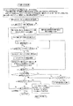
ここで、時間指定を再生時間(再生時の実時間)にすると、従来のVRと同じアクセス方法が可能となり、ユーザが再生時間でアクセス希望箇所を指定できるため、ユーザ希望が完全に反映されることになる。ただし、この方法は、ストリームの内容が十分に解析可能な場合に指定できる方法であり、十分に内容がわからない場合には転送時間単位で指定せざるを得ない。(再生時間で指定した場合、必ずしもIピクチャの先頭で再生を開始できるとは限らない。)再生開始のフレームがIで無い場合は、その直前のIよりデコードを開始し、目的のフレームまでデコードをした所で、表示を開始し、ユーザには指定されたフレームから再生開始したように見せる事により対応している。 Here, when the time designation is set to the reproduction time (actual time at the time of reproduction), the same access method as the conventional VR becomes possible, and the user can designate the desired access location by the reproduction time, so that the user's desire is completely reflected. It will be. However, this method can be specified when the contents of the stream can be sufficiently analyzed. If the contents are not sufficiently understood, it must be specified in units of transfer time. (If specified by the playback time, playback may not always start at the beginning of the I picture.) If the playback start frame is not I, the decoding starts from the immediately preceding I and decodes to the target frame. In response to this, the display is started, and the user is dealt with by making it appear as if playback has started from the designated frame.
また、参照するID13344は、再生するストリームの代表するストリームのPID(またはコンポーネントタグの値)を設定する方法と、マルチビューTVなどの場合などで、コンポーネントグループのIDを設定する方法が考えられる。また、参照するGPI番号13345を入れ、(再生中に)切り換える方法が考えられる。また、PG、CELLに特有のID番号を付け、途中のPG、CELLを削除しても変わらない番号でPG、CELLを指定できるようにしている。
As the
図33は、図1または図2に示したストリームオブジェクト用のデータユニット(SOBU)がどのように構成されるかの一例を説明する図である。1個のSOBU134は1以上のパケットグループ140で構成され、各パケットグループ140は、例えば16パック(1パック=1セクタ:2048バイト)で構成される。
FIG. 33 is a diagram illustrating an example of how the stream object data unit (SOBU) illustrated in FIG. 1 or 2 is configured. One
各パケットグループ140は、パケットグループヘッダ(404バイト)161と、1以上(ここでは170個)のパケット到着時間PAT(4バイト)163と、PATと同数の(ここでは170個)のMPEG−TSパケット(188バイト)162を含んで構成されている。各MPEG−TSパケット162はペアとなるPAT163を先頭に持ち、このPATにより各MPEG−TSが何時(装置に)到着したのかが分かるようになっている。
Each
パケットグループヘッダ161は、同期パターン151と、表示コントロール情報(DCI;Display Control Information)およびコピー世代管理情報(またはコピー制御情報CCI;Copy Control Information)152と、製造者情報(MNI;Manufacturer's information)(または業者情報MNFI)153とを含んで構成されている。
The
また、各MPEG−TSパケット162は、4バイトのヘッダ170とアダプテーションフィールドおよび/またはペイロード180を含んで構成されている。ここで、ヘッダ170は、同期バイト171と、トランスポート・エラー・インジケータ172と、ペイロードユニット開始インジケータ173と、トランスポート優先度174と、パケット識別子(PID)175と、トランスポート・スクランブル制御176と、アダプテーションフィールド制御177と、連続性指標178を含んで構成されている。
Each MPEG-
図34は、図33に示したパケットグループヘッダに含まれるDCI_CCIがどのように構成されるかの一例を説明する図である。有効性情報(DCI_CCI_SS)は1バイトで構成され、その中の1ビットのDCI_SSは、0で無効を示し、1で有効を示している。また、4ビットのCCI_SSは、0ビット目でAPSの無効/有効を示し、1ビット目でEPN、ICTの無効/有効を示し、2ビット目でCGMSの無効/有効を示し、3ビット目でRetentionの無効/有効を示している。 FIG. 34 is a diagram for explaining an example of how DCI_CCI included in the packet group header shown in FIG. 33 is configured. The validity information (DCI_CCI_SS) is composed of 1 byte, and 1-bit DCI_SS of the validity information is 0 for invalidity and 1 for validity. The 4-bit CCI_SS indicates invalidity / validity of APS at the 0th bit, invalidity / validity of EPN and ICT at the first bit, invalidity / validity of CGMS at the second bit, and at the third bit. Retention is disabled / enabled.
表示制御情報(DCI)には4バイト割り当てられ、ES毎に32ストリーム分のDCIが設定される。ストリームがない場合は、このDCIのフィールドは“0”で埋められる。このDCIの内訳は、先頭から順に、ES1〜ES32のアスペクトフラグ(“0”でアスペクト比4:3を示し、“1”でアスペクト比16:9を示す)が配置される。 Four bytes are allocated to the display control information (DCI), and DCI for 32 streams is set for each ES. When there is no stream, this DCI field is filled with “0”. The breakdown of the DCI includes ES1 to ES32 aspect flags ("0" indicates an aspect ratio of 4: 3 and "1" indicates an aspect ratio of 16: 9) in order from the top.
図35は、図34のDCI_CCIに含まれる各コピー管理情報CCIがどのように構成されるかの例(例1と例2)を説明する図である。コピー制御情報(CCI)には、ESIに入っているものと同じ内容で、デジタルコピー制御(00=コピー禁止、01=1回コピー許可、11=コピー禁止)と、アナログコピー制御(00=APS無し、01=APSタイプ1、10=APSタイプ2、11=APSタイプ3)と、EPN(0=コンテンツ保護、1=コンテンツ保護無し)と、ICT(Image_Constraint_Token:0でアナログビデオ出力解像度制限、1で制限無し)で構成されている場合と、さらに、リテンション情報(コピー禁止でRetention=0でstateで示される時間だけ一時保存を許可する)が入っている場合が考えられる。ここで、APSとはAnalog Protection Systemのことでこの一実施の形態ではマクロビジョン(R)を想定している。
FIG. 35 is a diagram for explaining an example (example 1 and example 2) of how each copy management information CCI included in DCI_CCI in FIG. 34 is configured. The copy control information (CCI) has the same contents as those contained in the ESI, digital copy control (00 = copy prohibited, 01 = copy once, 11 = copy prohibited), and analog copy control (00 = APS). None, 01 =
なお、同じESで同じパケットグループ内でCCI、DCIの変化しそうな場合は、パケットグループを一旦区切り、ダミーデータ(PAT=0x01、TSパケット=ALL0x00)で残りのパケットグループを埋め、次のパケットグループになるように設定する。つまり、パケットグループ内でCCI、DCIが変化しないようにアライン処理を行っている(図50参照)。 If CCI and DCI are likely to change within the same packet group with the same ES, the packet group is temporarily divided, the remaining packet group is filled with dummy data (PAT = 0x01, TS packet = ALL0x00), and the next packet group Set to be. That is, alignment processing is performed so that CCI and DCI do not change within the packet group (see FIG. 50).
図36は、この発明の他の実施の形態に係るファイル構造を説明する図である。図36は図3の変形例であり、図3のHR_TMAP.IFO/HR_TMAP.BUPの代わりに、VR用VOBタイムマップファイルHR_VTMAP.IFO/HR_VTMAP.BUPと、SR用SOBタイムマップファイルHR_STMAPx.IFO/HR_STMAPx.BUPを設けている。 FIG. 36 is a view for explaining the file structure according to another embodiment of the present invention. FIG. 36 is a modification of FIG. 3, and HR_TMAP. IFO / HR_TMAP. Instead of BUP, a VOB time map file for VR HR_VTMAP. IFO / HR_VTMAP. BUP and SR SOB time map file HR_STMAPx. IFO / HR_STMAPx. BUP is provided.
図37は、図36のDVD_HDVRディレクトリに含まれるタイムマップファイルHR_VTMAP.IFO/HR_STMPx.IFO、もしくは図6のHDVR_VMGの末尾に配置されたタイムマップテーブルTMAPT(例2)が、どのように構成されるかの一例を説明する図(図19の変形例)である。図36のように、SOB、VOB別にTMAPTが記録される場合は、図37のようにVTMAPT、STMAPTは別々の構造を取る。図37において、VTMAPTは、VTMAPTIとVTMAP_SRPT(VTMAPのサーチテーブル情報:VTMAP_SRP#1〜#q)とVTMAP#で構成される。また、STMAPTは、STMAPTIと、STMAP_SRPT(STMAPのサーチテーブル情報:STMAP_SRP#1〜#q)とSTMAP#で構成される。
FIG. 37 shows a time map file HR_VTMAP. Included in the DVD_HDVR directory of FIG. IFO / HR_STMPx. FIG. 20 is a diagram (an example of a modification of FIG. 19) illustrating an example of how the time map table TMAPT (example 2) arranged at the end of the IFO or HDVR_VMG in FIG. 6 is configured. When TMAPT is recorded for each SOB and VOB as shown in FIG. 36, VTMAPT and STMAPT have different structures as shown in FIG. In FIG. 37, VTMAPT is composed of VTMAPTI, VTMAP_SRPT (VTMAP search table information:
図38は、図37のVTMAPTに含まれる各種情報がどのように構成されるかの一例を説明する図である。図38において、VTMAPTIは、VMG_ID(VMGIの先頭に在るVMG_IDと同じ値)と、VTMAPT_EA(VTMAPのエンドアドレス)と、VERN(TMAPのバージョン情報)と、IFO_LAST_MOD_TM(TMAPTの更新日時情報、HR_MANGR.IFOと同じ値)で構成される。さらに、VTMAP_SRPTIはVTMAP_SRP_Ns(サーチ情報総数)で構成され、VTMAP_SRPはVTMAP_SA(VTMAPのスタートアドレス)とVOBU_ENT_Ns(VOBU_ENTの総数)で構成され、VTMAPは1以上のVOBU_ENTで構成されている。 FIG. 38 is a diagram illustrating an example of how various types of information included in VTMAPT in FIG. 37 are configured. 38, VTMAPTI includes VMG_ID (the same value as VMG_ID at the beginning of VMGI), VTMAPT_EA (VTMAP end address), VERN (TMAP version information), and IFO_LAST_MOD_TM (TMAPT update date / time information, HR_MANGR. (Same value as IFO). Furthermore, VTMAP_SRPTI is composed of VTMAP_SRP_Ns (total number of search information), VTMAP_SRP is composed of VTMAP_SA (start address of VTMAP) and VOBU_ENT_Ns (total number of VOBU_ENT), and VTMAP is composed of one or more VOBU_ENTs.
図39は、図37のSTMAPTに含まれる各種情報がどのように構成されるかの一例を説明する図である。図39において、STMAPTIは、VMG_IDと、STMAPT_EA(STMAPのエンドアドレス)と、VERNと、IFO_LAST_MOD_TMで構成される。さらに、STMAP_SRPTIはSTMAP_SRP_Nsで構成される。そして、STMAP_SRPはSTMAP_SA(STMAPのスタートアドレス)と、ES_TMAPI_Ns(ES_TMAPの総数)と、ES_TMAPI_GIで構成される。そして、STMAPは、1以上のES_TMAPで構成される。 FIG. 39 is a diagram for explaining an example of how various information included in the STMAPT in FIG. 37 is configured. In FIG. 39, STMAPTI is composed of VMG_ID, STMAPT_EA (STMAP end address), VERN, and IFO_LAST_MOD_TM. Furthermore, STMAP_SRPTI is composed of STMAP_SRP_Ns. STMAP_SRP is composed of STMAP_SA (STMAP start address), ES_TMAPI_Ns (total number of ES_TMAP), and ES_TMAPI_GI. The STMAP is composed of one or more ES_TMAPs.
図40は、図39のSTMAP_SRP#およびSTMAPに含まれるES_TMAPI_GIおよびES_TMAP#が、どのような情報を格納するのかの一例を説明する図である。ES_TMAP_GIはSOBU_ENT_Ns(SOBU_ENTの総数)で構成され、各ES_TMAPは1以上のVOBU_ENTで構成されている。なお、TMAP_SRPは昇順にTMAPを指すとは限らないが、SRPで個々のTMAPをポイントするので問題はなく、TMAP間にごみデータが入っても良い(例えばTMAP#1とTMAP#3の間に無意味なデータがあっても問題ない)。
FIG. 40 is a diagram illustrating an example of what information is stored in ES_TMAPI_GI and ES_TMAP # included in STMAP_SRP # and STMAP in FIG. 39. ES_TMAP_GI is composed of SOBU_ENT_Ns (total number of SOBU_ENT), and each ES_TMAP is composed of one or more VOBU_ENTs. Note that TMAP_SRP does not necessarily indicate TMAP in ascending order, but there is no problem because it points to each TMAP in SRP, and garbage data may enter between TMAPs (for example, between
図41は、この発明の一実施の形態に係るデータ構造を利用して、情報記録媒体(光ディスク、ハードディスク等)にAV情報(デジタルTV放送プログラム等)を記録し再生する装置の一例を説明するブロック図である。この装置(デジタルビデオレコーダ/ストリーマ)は、図41に示すように、MPU部80、キー入力部103、リモコン103aからのユーザ操作情報を受け取るリモコン受信部103b、表示部104、デコーダ部59、エンコーダ部79、システムタイムカウンタ(STC)部102、データプロセサ(D−PRO)部52、一時記憶部53、DVD−RAM等の記録可能光ディスク100に対して情報の記録/再生を行うディスクドライブ部51、ハードディスクドライブ(HDD)100a、ビデオミキシング(Vミキシング)部66、フレームメモリ部73、アナログTV用D/A変換部67、アナログTVチューナ部82、地上波デジタルチューナ部89、および、衛星アンテナ83aに接続されるSTB(Set Top Box)部83により構成されている。さらに、この装置は、ストリーマとしてデジタル入出力に対応するため、IEEE1394などのデジタルI/F74を備えている。なお、STC部102は、図33のPAT_Baseに合わせて、27MHzベースでクロックカウントを行うように構成されている。
FIG. 41 illustrates an example of an apparatus for recording and reproducing AV information (digital TV broadcast program, etc.) on an information recording medium (optical disc, hard disk, etc.) using the data structure according to an embodiment of the present invention. It is a block diagram. As shown in FIG. 41, this apparatus (digital video recorder / streamer) includes an
STB部83は、受信したデジタル放送データのデコードを行なってAV信号(デジタル)を発生させ、そのAV信号をストリーマ内のエンコーダ部79、デコーダ部59およびD/A変換器67を介してTV68に送り、受信したデジタル放送の内容を表示させることが可能に構成されている。あるいは、STB部83は、デコード後のAV信号(デジタル)を直接Vミキシング部66に送り、そこからD/A変換器67を介してアナログAV信号をTV68に送ることも可能に構成されている。
The
ところで、図41の装置はビデオレコーディングとストリームレコーディングの両機能を備えたレコーダを構成しているので、ビデオレコーディングでは不要な構成(IEEE1394I/Fなど)やストリームレコーディングでは不要な構成(AV入力用のA/D変換器84、オーディオエンコード部86、ビデオエンコード部87など)を備えている。
By the way, since the apparatus of FIG. 41 constitutes a recorder having both video recording and stream recording functions, it is not necessary for video recording (such as IEEE 1394 I / F) or unnecessary for stream recording (for AV input). A /
エンコーダ部79内は、A/D変換器84、ビデオエンコード部87、ビデオエンコード部87への入力切換セレクタ85、オーディオエンコード部86、(図示しないが必要に応じて)副映像エンコード部、フォーマット部90、バッファメモリ部91を含んで構成されている。
The
また、デコード部59は、メモリ60aを内蔵する分離部60、メモリ61aおよび縮小画像(サムネールなど)の生成部62を内蔵するビデオデコード部61、副映像(SP)デコード部63、メモリ64aを内蔵するオーディオデコード部64、TSパケット転送部101、ビデオプロセサ(V−PRO)部65、オーディオ用D/A変換器70より構成されている。このD/A変換器70からのアナログ出力(モノラル、ステレオ、あるいはAAC5.1CHサラウンド)は、図示しないAVアンプ等に入力され、必要本数のスピーカ72が駆動される。
The
ところで、録画中のコンテンツをTV68に表示するために、記録するストリームデータを、D−PRO部52に送るのと同時に、デコーダ部59へも同時に送り、その再生を行うことができる。この場合、MPU部80はデコーダ部59へ再生時の設定を行い、その後はデコーダ部59が自動的に再生処理を行う。
By the way, in order to display the content being recorded on the
D−PRO部52は、例えば16パック(あるいは32パックもしくは64kバイト)毎にまとめてECCグループとし、ECCをつけてドライブ部51へ送る。ただし、ドライブ部51がディスク100への記録準備が出来ていない場合には、一時記憶部53へ転送し、データを記録する準備が出来るまで待ち、用意が出来た段階で記録を開始する。ここで、一時記憶部53は高速アクセスで数分以上の記録データを保持するため、大容量メモリが想定される。この一時記憶部53は、HDD100aの一部を利用して構築することも可能である。なお、MPU部80は、ファイルの管理領域などを読み書きするために、D−PRO部52へ専用のマイコンバスを通して読み書きできるように構成されている。
The D-
図41の装置では、記録媒体として第1にDVD−RAM/−RW/−R/Blueメディア(ブルーレーザを用いる録再可能メディア)等の光ディスク100を想定し、その補助記憶装置としてハードディスクドライブ(HDD)100a(および/または図示しない大容量メモリカード等)を想定している。
In the apparatus of FIG. 41, an
これら複数媒体の使い方としては、例えば次のようなものがある。すなわち、HDD100aに図1〜図40のデータ構造(フォーマット)を利用してストリームレコーディングを行う。そして、HDD100aに記録されたストリームレコーディングコンテンツのうち、ユーザが保存したいと希望するプログラムについては、ディスク100にそのままストリームレコーディング(ダイレクトコピーあるいはデジタルダビング)する(コピー制御情報CCIでコピーが禁止されていない場合)。こうすれば、デジタル放送のオリジナルと同等のクォリティを持つ所望プログラムだけをディスク100に纏めることができる。さらに、ディスク100にコピーされたストリームレコーディングコンテンツはこの発明のデータ構造を利用しているので、ストリームレコーディングであるにも拘わらず、タイムサーチ等の特殊再生が容易なものとなる。
Examples of how to use these multiple media are as follows. That is, stream recording is performed on the
以上のような特徴を持つデジタルレコーダ(DVD−RAM/−RW/−R/BlueメディアとHDDとの組み合わせで構成されたストリーマ/ビデオレコーダ)の具体例が、図41の装置である。図41のデジタルレコーダは、大きくいって、チューナ部(82、83、89)と、ディスク部(100、100a)と、エンコーダ部79と、デコーダ部59と、制御部(80)を含んで構成されている。
A specific example of the digital recorder (streamer / video recorder constituted by a combination of DVD-RAM / -RW / -R / Blue media and HDD) having the above-described features is the apparatus shown in FIG. The digital recorder shown in FIG. 41 includes a tuner unit (82, 83, 89), a disk unit (100, 100a), an
衛星デジタルTV放送は、放送局より通信衛星を通して放送される。放送されたデジタルデータは、STB部83で受信され再生される。このSTB83は、放送局から配給されるキーコードを元に、スクランブルされたデータを伸張し再生を行う装置である。このとき、放送局からのスクランブルが解除される。ここで、データがスクランブルされているのは、放送局と受信契約を行っていないユーザが放送番組を不正に視聴することを防ぐ意味で行っている。
The satellite digital TV broadcast is broadcast from a broadcasting station through a communication satellite. The broadcast digital data is received and reproduced by the
STB部83内では、図示しないが、放送されたデジタルデータは、チューナシステムにより受信される。受信されたデータは、そのまま再生される場合には、デジタル伸張部でスクランブルが解除され、MPEGデコーダ部で受信データがデコードされ、ビデオエンコーダ部でTV信号に変換され、このTV信号がD/A変換器67を介して外部に送出される。これにより、STB部83で受信されたデジタル放送番組をアナログTV68で表示できるようになる。
In the
地上波デジタル放送は、通信衛星を経由しない(および無料放送ではスクランブルが掛けられない)点を除き、衛星放送と同様に受信され処理される。すなわち、地上波デジタル放送は地上波デジタルチューナ部89で受信され、そのまま再生される場合はデコード後のTV信号がD/A変換器67を介して外部に送出される。これにより、地上波デジタルチューナ部89で受信されたデジタル放送番組をアナログTV68で表示できる。地上波アナログ放送は、地上波チューナ部82で受信され、そのまま再生される場合は受信されたアナログTV信号が外部に送出される。これにより、地上波チューナ部82で受信されたアナログ放送番組をTV68で表示できる。
Terrestrial digital broadcasts are received and processed in the same way as satellite broadcasts, except that they do not go through communication satellites (and are not scrambled in free broadcasts). That is, the terrestrial digital broadcast is received by the terrestrial
外部AV入力81からアナログ入力されたアナログビデオ信号は、そのままストレートにTV68に送出することも可能であるが、A/D変換器84で一旦A/D変換し、その後D/A変換器67でアナログビデオ信号に戻してから、外部TV68側へ送出するように構成することもできる。このように構成すると、ジッタの多いアナログVCR再生信号が外部AV入力81から入力された場合でも、ジッタのない(デジタルタイムベースコレクションされた)アナログビデオ信号をTV68側に出力できる。
The analog video signal analog-input from the
デジタルI/F(IEEE1394インターフェイス)74からデジタル入力されたデジタルビデオ信号は、D/A変換器67を介して外部TV68側へ送出される。これにより、デジタルI/F74に入力されたデジタルビデオ信号をTV68で表示できる。
A digital video signal digitally input from a digital I / F (IEEE 1394 interface) 74 is sent to the
衛星デジタル放送、地上波デジタル放送、あるいはデジタルI/F74から入力されたビットストリーム(MPEG−TS)は、図1(e)のストリームオブジェクト132として、ディスク100(および/またはHDD100a)のストリームオブジェクト群記録領域131(図1(d))にストリームレコーディングできる。また、地上波アナログ放送あるいはA/V入力81からのアナログビデオ信号は、ディスク100(および/またはHDD100a)のVRオブジェクト群記録領域122(図1(d))にビデオレコーディングできる。
A bit stream (MPEG-TS) input from satellite digital broadcast, terrestrial digital broadcast, or digital I /
なお、地上波アナログ放送あるいはA/V入力81からのアナログビデオ信号は、一旦A/D変換したあと、ビデオレコーディングでなくてストリームレコーディングするように装置を構成することもできる。逆に、衛星デジタル放送、地上波デジタル放送、あるいはデジタルI/F74から入力されたビットストリーム(MPEG−TS)は、(必要なフォーマットコンバートをしてから)ストリームレコーディングでなくてビデオレコーディングするように装置を構成することも可能である。
Note that the apparatus can be configured so that the analog video signal from the terrestrial analog broadcast or the A /
ストリームレコーディングまたはビデオレコーディングの記録/再生制御は、メインMPU部80(記録/再生制御部80X)により、ROM80Cに書き込まれたファームウエア(後述する図42〜図68の動作に対応した制御プログラム等)に基づいて行われる。MPU部80は、ストリームレコーディングおよびビデオレコーディングの管理データ作成部80Bを持ち、ワークRAM部80Aを作業エリアとして種々な管理情報を作成し、作成した管理情報を、図1(d)のAVデータ管理情報記録領域130に適宜記録する。また、MPU部80は、AVデータ管理情報記録領域130に記録された管理情報を再生し、再生した管理情報に基づき種々な制御(図42〜図68)を行う。なお、MPU部80のROM80Cには、図41の装置のメーカーID情報等を書き込んでおくことができる。
Recording / reproduction control of stream recording or video recording is performed by firmware written in the
図41の装置で用いる媒体100(100a)の特徴を簡単に纏めると、次のようになる。すなわち、この媒体は、管理領域130とデータ領域131で構成され、データ領域にはデータが複数のオブジェクトデータ(SOB)に分かれて記録され、それぞれのオブジェクトデータはデータユニット(SOBU)の集まりで構成される。そして、1つのデータユニット(SOBU)は、MPEG−TSに準じたデジタル放送信号をTSパケット毎に複数パケットでパケットグループ化したパケットグループにより構成される(図1、図33参照)。一方、前記管理領域130は再生手順を管理する情報としてPGC情報(PGCI)を持ち、このPGC情報はセル情報(CI)を含んで構成される。さらに、管理領域130内にオブジェクトデータ(SOB)を管理する情報を持つ。
The characteristics of the medium 100 (100a) used in the apparatus of FIG. 41 can be summarized as follows. That is, this medium is composed of a
図41の装置は、上記のようなデータ構造を持つ媒体100(100a)に対して、ビデオレコーディングの他にストリームレコーディングを行うことができる。その際、TSパケットのストリーム内からプログラムマップテーブルPMTやサービス情報SIを取り出すために、MPU部80はサービス情報取り出し部(図示せず;管理データ作成部80Bの一部を構成するファームウエア)を持つように構成される。またこのサービス情報取り出し部で取り出した情報を元に、属性情報(PCR_パック番号あるいはPCR_LB数番号など)を作成する属性情報作成部(図示せず;管理データ作成部80Bの一部を構成するファームウエア)を持つように構成される。
The apparatus shown in FIG. 41 can perform stream recording on medium 100 (100a) having the above data structure in addition to video recording. At this time, in order to extract the program map table PMT and the service information SI from the TS packet stream, the
図41の装置において、記録時の信号の流れは、例えば次のようになる。すなわち、STB部(または地上波デジタルチューナ)で受け取ったTSパケットデータは、フォーマッタ部でパケットグループ化されワーク(バッファメモリ部91)へ保存し、一定量たまった時点(1またはその整数倍のCDA分がたまった段階で)でディスクに記録される。この時の動作は、TSパケットを受信すると170パケットづつグルーピング化し、パケットグループヘッダを作成する。 In the apparatus of FIG. 41, for example, the signal flow during recording is as follows. That is, the TS packet data received by the STB unit (or terrestrial digital tuner) is packet-grouped by the formatter unit and stored in the work (buffer memory unit 91). It is recorded on the disc when the minutes are accumulated. In this operation, when TS packets are received, 170 packets are grouped and a packet group header is created.
また、地上波チューナやライン入力から入力されたアナログ信号は、A/D部でデジタル変換される。そのデジタル信号は、各エンコーダ部へ入力される。ビデオ信号はビデオエンコード部へ、オーディオ信号はオーディオエンコード部へ、文字放送などの文字データはSPエンコード部(図示せず)へ入力され、ビデオ信号はMPEG圧縮され、オーディオ信号はAC3圧縮またはMPEGオーディオ圧縮がなされ、文字データはランレングス圧縮される。 An analog signal input from a terrestrial tuner or line input is digitally converted by an A / D unit. The digital signal is input to each encoder unit. The video signal is input to the video encoding unit, the audio signal is input to the audio encoding unit, character data such as teletext is input to the SP encoding unit (not shown), the video signal is MPEG compressed, and the audio signal is AC3 compressed or MPEG audio. Compression is performed, and the character data is run-length compressed.
各エンコーダ部から、圧縮データが、パック化(あるいはブロック化)された場合に2048バイトになるようにパック化(あるいはブロック化)されて、フォーマッタ部へ入力される。フォーマッタ部では、各パケット(あるいは各ブロック)が多重化され、D−PRO部へ送られる。D−PRO部では、16または32パケット(16または32ブロック)毎にECCブロックを形成し、エラー訂正データを付け、ドライブ部によりディスクに記録する。 Each encoder unit packs (or blocks) the compressed data to 2048 bytes when packed (or blocks) and inputs the data to the formatter unit. In the formatter unit, each packet (or each block) is multiplexed and sent to the D-PRO unit. In the D-PRO unit, an ECC block is formed every 16 or 32 packets (16 or 32 blocks), error correction data is attached, and the drive unit records the data on a disk.
ここで、ドライブ部がシーク中やトラックジャンプなどの場合のため、ビジー状態の場合には、HDDバッファ部へ入れられ、RAMドライブ部の準備ができるまで待つこととなる。さらに、フォーマッタ部では、録画中、各切り分け情報を作成し、定期的にMPU部へ送る(GOP先頭割り込みなど)。切り分け情報としては、VOBU(SOBU)のパック数(あるいはLB数)、VOBU(SOBU)先頭からのIピクチャのエンドアドレス、VOBU(SOBU)の再生時間などがある。 Here, since the drive unit is in a seek state or a track jump, when it is busy, it is put in the HDD buffer unit and waits until the RAM drive unit is ready. Furthermore, the formatter unit creates segmentation information during recording and periodically sends it to the MPU unit (GOP head interrupt, etc.). The segmentation information includes the number of VOBU (SOBU) packs (or the number of LBs), the end address of the I picture from the beginning of the VOBU (SOBU), the playback time of the VOBU (SOBU), and the like.
記録時の信号の流れは、STB部(または地上波デジタルチューナ)で受け取ったTSパケットデータが、フォーマッタ部でパケットグループ化され、ワークRAMに保存され、一定量たまった時点(1またはその整数倍のCDA分がたまった段階で)でディスクに記録される。 The signal flow during recording is as follows: TS packet data received by the STB unit (or terrestrial digital tuner) is packet-grouped by the formatter unit, stored in the work RAM, and accumulated a certain amount (1 or an integer multiple thereof) (When the CDA is accumulated), it is recorded on the disc.
また、再生時の信号の流れは、ディスクからドライブ部よりデータを読み出し、D−PRO部でエラー訂正を行い、デコード部へ入力される。MPU部は入力されるデータがVRデータか、SRデータかの種別を判定し(セルタイプにより判定できる)、デコーダ部に再生前にその種別を設定する。SRデータの場合、MPU部は再生するセル情報CIより、再生するPMT_IDを決め、該当するPMTより、再生する各アイテム(ビデオ、オーディオ等)のPIDを決め、デコーダ部へ設定する。デコーダ部は、そのPIDを元に、分離部で各TSパケットを各デコード部へ送る。さらに、TSパケット転送部へ送り、到着時間に従って、STB部(1394I/F部)へTSパケットの形で送信する。各デコード部は、デコードを行い、D/A部でアナログ信号に変換し、TVで表示する。VRデータの場合は、分離部は、固定のIDに従い、各デコード部へ送る。各デコード部は、デコードを行い、D/A部でアナログ信号に変換し、TVで表示する。 The signal flow during reproduction is read from the disk from the drive unit, corrected by the D-PRO unit, and input to the decoding unit. The MPU unit determines whether the input data is VR data or SR data (can be determined by the cell type), and sets the type in the decoder unit before reproduction. In the case of SR data, the MPU unit determines the PMT_ID to be reproduced from the cell information CI to be reproduced, determines the PID of each item (video, audio, etc.) to be reproduced from the corresponding PMT, and sets it in the decoder unit. Based on the PID, the decoder unit sends each TS packet to each decode unit by the separation unit. Further, the packet is sent to the TS packet transfer unit, and transmitted to the STB unit (1394 I / F unit) in the form of a TS packet according to the arrival time. Each decoding unit performs decoding, converts the analog signal into a D / A unit, and displays it on the TV. In the case of VR data, the separation unit sends to each decoding unit according to a fixed ID. Each decoding unit performs decoding, converts the analog signal into a D / A unit, and displays it on the TV.
なお、再生時は、ディスクから読み出したパックデータを分離部で解析し、TSパケットが入っているパックの場合には、TSパケット転送部へ送り、さらに、その後、各デコーダへ送って、再生を行う。STBへ転送する場合(あるいはデジタルTV等の外部機器へ送信する場合)は、TSパケット転送部は、そのデータを到着時と同じ時間間隔で、TSパケットのみを転送する。STB部は、デコードを行い、AV信号を発生させ、そのAV信号をストリーマ内ビデオエンコーダ部を通して、TVへ表示する。 During playback, the pack data read from the disk is analyzed by the separation unit. If the pack contains a TS packet, it is sent to the TS packet transfer unit, and then sent to each decoder for playback. Do. When transferring to the STB (or when transmitting to an external device such as a digital TV), the TS packet transfer unit transfers only the TS packet at the same time interval as when it arrived. The STB unit performs decoding, generates an AV signal, and displays the AV signal on the TV through the intra-streamer video encoder unit.
ところで、デジタルTV放送やインターネットなど有線を使用した放送などの、圧縮動画を放送(配信)する方式において、共通の基本フォーマットであるMPEG−TS方式は、パケットの管理データ部分とペイロードに分かれる。ペイロードには、再生されるべき対象のデータがスクランブルの掛かった状態で含まれている。ARIBによると、PAT(Program Association Table)、PMT(Program Map Table)、SI(Service Information)に関しては、スクランブルされていない。また、PMTやSI(SDT:Service Description Table、 EIT:Event Information Table、BAT:Bouquet association Table)を利用してさまざまな管理情報を作成することができる。 By the way, in a system for broadcasting (distributing) compressed moving images, such as digital TV broadcasting and broadcasting using wired communication such as the Internet, the MPEG-TS system, which is a common basic format, is divided into a management data portion of a packet and a payload. The payload includes data to be reproduced in a scrambled state. According to ARIB, PAT (Program Association Table), PMT (Program Map Table), and SI (Service Information) are not scrambled. Various management information can be created using PMT and SI (Service Description Table, EIT: Event Information Table, BAT: Bouquet association Table).
再生対象としては、MPEGビデオデータやDolby AC3(R)オーディオデータやMPEGオーディオデータ、データ放送データなど、さらに、直接、再生対象には関係ないが、再生する上で必要なPAT、PMT、SIなどの情報(番組情報等)などがある。PATには、番組毎のPMTのPID(Packet Identification)が含まれており、さらにPMTにはビデオデータやオーディオデータのPIDが記録されている。 As playback targets, MPEG video data, Dolby AC3 (R) audio data, MPEG audio data, data broadcast data, and the like, and PAT, PMT, SI, etc., which are not directly related to the playback target but are necessary for playback. Information (program information, etc.). The PAT includes a PID (Packet Identification) of the PMT for each program, and further, PIDs of video data and audio data are recorded in the PMT.
STB(Set Top Box)の通常の再生手順としては、EPG情報により、ユーザが番組を決定すると、目的の番組の開始時間に、PATを読み込む。そのデータを元に、希望の番組に属するPMTのPIDを決定し、そのPIDに従って、目的のPMTを読み出す。そして、そこに含まれる再生すべきビデオ、オーディオパケットのPIDを決定し、PMTやSIにより、ビデオ、オーディオの属性を読み出し、各デコーダへセットする。そして、前記ビデオ、オーディオデータを、PIDに従って切り出して、再生する。ここで、PAT、PMT、SI等は、途中再生にも使用するために、数100ms毎に、送信されてくる。 As a normal playback procedure of STB (Set Top Box), when the user determines a program based on the EPG information, the PAT is read at the start time of the target program. Based on the data, the PID of the PMT belonging to the desired program is determined, and the target PMT is read according to the PID. Then, PIDs of video and audio packets to be reproduced included therein are determined, video and audio attributes are read out by PMT and SI, and set to each decoder. Then, the video and audio data are cut out according to the PID and reproduced. Here, PAT, PMT, SI, and the like are transmitted every several hundreds of milliseconds to be used for intermediate playback.
記録時の信号の流れは、STB部(または地上波デジタルチューナ)で受け取ったTSパケットデータは、フォーマッタ部で、パケットグループ化されワークRAMへ保存し、一定量たまった時点でディスクに記録される。この時の動作は、TSパケットを受信すると170パケットづつグルーピング化し、パケットグループヘッダを作成しする。 The signal flow at the time of recording is that TS packet data received by the STB unit (or terrestrial digital tuner) is packet-grouped by the formatter unit and stored in the work RAM, and is recorded on the disc when a certain amount of data is accumulated. . In this operation, when TS packets are received, 170 packets are grouped and a packet group header is created.
また、地上波チューナやライン入力から入力されたアナログ信号は、A/D部でデジタル変換される。そのデジタル信号は、各エンコーダ部へ入力される。ビデオ信号はビデオエンコード部へ、オーディオ信号はオーディオエンコード部へ、文字放送などの文字データはSPエンコード部へ入力され、ビデオ信号はMPEG圧縮され、オーディオ信号はAC3圧縮またはMPEGオーディオ圧縮がなされ、文字データはランレングス圧縮される。 An analog signal input from a terrestrial tuner or line input is digitally converted by an A / D unit. The digital signal is input to each encoder unit. The video signal is input to the video encoding unit, the audio signal is input to the audio encoding unit, character data such as teletext is input to the SP encoding unit, the video signal is MPEG-compressed, and the audio signal is AC3 compressed or MPEG audio-compressed. Data is run-length compressed.
各エンコーダ部(VR用)から、圧縮データがパック化された場合に2048バイトになるようにパケット化されて、フォーマッタ部へ入力される。フォーマッタ部では、各パケットがパック化され、さらに、多重化され、D−PRO部へ送られる。 From each encoder unit (for VR), when the compressed data is packed, it is packetized so that it becomes 2048 bytes and is input to the formatter unit. In the formatter unit, each packet is packed, further multiplexed, and sent to the D-PRO unit.
D−PRO部では、16または32パック毎にECCブロックを形成し、エラー訂正データを付け、ドライブ部によりディスクに記録する。ここで、ドライブ部がシーク中やトラックジャンプなどの場合のため、ビジィー状態の場合には、HDDバッファ部へ入れられ、DVD−RAMドライブ部の準備ができるまで待つこととなる。 In the D-PRO unit, ECC blocks are formed every 16 or 32 packs, error correction data is attached, and the drive unit records the data on a disk. Here, since the drive unit is in a seek state or a track jump, in the busy state, the drive unit is put in the HDD buffer unit and waits until the DVD-RAM drive unit is ready.
さらに、フォーマッタ部では、録画中、各切り分け情報を作成し、定期的にMPU部へ送る(GOP先頭割り込みなど)。切り分け情報としては、VOBU(SOBU)のパック数、VOBU(SOBU)先頭からのIピクチャのエンドアドレス、VOBU(SOBU)の再生時間などである。 Furthermore, the formatter unit creates segmentation information during recording and periodically sends it to the MPU unit (GOP head interrupt, etc.). The segmentation information includes the number of packs of VOBU (SOBU), the end address of the I picture from the beginning of the VOBU (SOBU), the playback time of VOBU (SOBU), and the like.
また、再生時の記録の流れは、ディスクからドライブ部よりデータを読み出し、D−PRO部でエラー訂正を行い、デコード部へ入力される。MPU部は入力されるデータがVRデータか、SRデータかの種別を判定し(Cell TYPEより判定する)、デコーダ部に再生前にその種別を設定する。SRデータの場合、MPU部は再生するCELLIより、再生するPMT_IDを決め、該当するPMTより、再生する各アイテム(ビデオ、オーディオ等)のPIDを決め、デコーダ部へ設定する。デコーダ部は、そのPIDを元に、分離部で各TSパケットを各デコード部へ送る。さらに、TSパケット転送部へおくり、到着時間にしたがって、STB部(1394I/F部)へTSパケットの形で送信する。各デコード部は、デコードを行い、D/A部でアナログ信号に変換し、TVで表示する。VRデータの場合、分離部は、固定のIDに従い、各デコード部へ送る。各デコード部は、デコードを行い、D/A部でアナログ信号に変換し、TVで表示する。 In the recording flow during reproduction, data is read from the disk from the drive unit, error-corrected by the D-PRO unit, and input to the decoding unit. The MPU unit determines whether the input data is VR data or SR data (determined by Cell TYPE), and sets the type in the decoder unit before reproduction. In the case of SR data, the MPU unit determines the PMT_ID to be reproduced from the CELLI to be reproduced, determines the PID of each item (video, audio, etc.) to be reproduced from the corresponding PMT, and sets it in the decoder unit. Based on the PID, the decoder unit sends each TS packet to each decode unit by the separation unit. Further, the packet is sent to the TS packet transfer unit, and is transmitted in the form of a TS packet to the STB unit (1394 I / F unit) according to the arrival time. Each decoding unit performs decoding, converts the analog signal into a D / A unit, and displays it on the TV. In the case of VR data, the separation unit sends it to each decoding unit according to a fixed ID. Each decoding unit performs decoding, converts the analog signal into a D / A unit, and displays it on the TV.
ここで、TVに表示するために、デコーダ部へD−PRO部と同時に送り、再生を行う。ただし、この場合、MPU部はデコーダ部へ再生時の設定を行い、その後はデコーダが自動的に再生を行う。D−PRO部は16パック毎にまとめてECCグループとして、ECCをつけてドライブ部へ送る。ただし、ドライブ部がディスクへの記録準備が出来ていない場合には、一時記憶部へ転送し、データを記録する準備が出来るまで待ち、用意が出来た段階で記録を開始する。ここで、一時記憶部は高速アクセスで数分以上の記録データを保持するため、大容量メモリが想定される。ただし、マイコンは、ファイルの管理領域などを読み書きするために、D−PRO部へマイコンバスを通して、読み書きすることが出来る。 Here, in order to display on the TV, the data is sent to the decoder unit at the same time as the D-PRO unit and reproduced. However, in this case, the MPU unit makes settings for reproduction in the decoder unit, and then the decoder automatically performs reproduction. The D-PRO unit collects every 16 packs as an ECC group, attaches the ECC, and sends it to the drive unit. However, if the drive unit is not ready for recording on the disk, it is transferred to the temporary storage unit, waits until it is ready to record data, and starts recording when it is ready. Here, since the temporary storage unit holds recording data of several minutes or more by high-speed access, a large-capacity memory is assumed. However, the microcomputer can read and write to the D-PRO unit through the microcomputer bus in order to read and write the file management area and the like.
また、再生時は、ディスクから読み出したパックデータを分離部で解析し、TSパケットが入っているパックの場合には、TSパケット転送部へおくり、さらに、その後、各デコーダへ送られ、再生を行う。STBへ転送する場合(外部へ送信する場合:デジタルTV等)は、TSパケット転送部は、そのデータを到着時と同じ時間間隔で、TSパケットのみを転送する。 During playback, the pack data read from the disk is analyzed by the separation unit. If the pack contains TS packets, it is sent to the TS packet transfer unit, and then sent to each decoder for playback. Do. When transferring to the STB (when transmitting to the outside: digital TV or the like), the TS packet transfer unit transfers only the TS packet at the same time interval as the arrival time.
STB部は、デコードを行い、AV信号を発生させ、そのAV信号をストリーマ内ビデオエンコーダ部を通して、TVへ表示する。 The STB unit performs decoding, generates an AV signal, and displays the AV signal on the TV through the intra-streamer video encoder unit.
図42は、図41の装置の全体の動作の一例を説明するフローチャート図(全体動作処理フロー)である。ここでのデータ処理は、図42に示すように録画処理、再生処理、データ転送処理(STBへのデジタル出力処理など)、番組設定処理、編集処理の5通りとなる。 FIG. 42 is a flowchart (overall operation processing flow) for explaining an example of the overall operation of the apparatus shown in FIG. As shown in FIG. 42, there are five types of data processing: recording processing, playback processing, data transfer processing (digital output processing to STB, etc.), program setting processing, and editing processing.
例えば図41の装置の電源がオンされると、MPU部80は、(工場出荷時またはユーザが設定した後の)初期設定を行い(ステップST10)、表示設定を行って(ステップST12)、ユーザ操作を待つ。ユーザがキー入力部103またはリモコン103aからキー入力を行うと(ステップST14)、MPU部80はそのキー入力の内容を解釈する(ステップST16)。この入力キー解釈の結果に応じて、以下の4つのデータ処理が、適宜実行される。
For example, when the apparatus of FIG. 41 is turned on, the
すなわち、キー入力が例えばタイマ予約録画設定のキー操作であれば、番組設定処理に入る(ステップST20)。キー入力が録画開始のキー操作であれば、録画処理に入る(ステップST22)。キー入力が再生開始のキー操作であれば、再生処理に入る(ステップST24)。キー入力がSTBへデジタル出力させるキー操作であれば、デジタル出力処理に入る(ステップST26)。編集処理のキー操作であれば、編集処理に入る(ステップST28)。 That is, if the key input is a key operation for setting timer reservation recording, for example, the program setting process is started (step ST20). If the key input is a key operation for starting recording, the recording process is started (step ST22). If the key input is a key operation for starting playback, playback processing is started (step ST24). If the key input is a key operation for digital output to the STB, digital output processing is started (step ST26). If the key operation is an editing process, the editing process is started (step ST28).
ステップST20〜ST28の処理は、そのタスク毎に適宜並列処理される。例えば、再生処理中(ST24)にSTBへデジタル出力する処理(ST26)が並列に実行される。あるいは、タイマ予約録画でない録画処理中(ST22)に新たな番組設定処理(ST20)を並列に処理するように構成することができる。あるいは、高速アクセス可能なディスク記録の特徴を生かし、録画処理(ST22)中に再生処理(ST24)とデジタル出力処理(ST26)を並列処理するように構成することもできる。HDDへの録画中にディスクの編集処理(ステップST28)を行うように構成することも可能である。 The processes in steps ST20 to ST28 are appropriately performed in parallel for each task. For example, during the reproduction process (ST24), a process (ST26) for digital output to the STB is executed in parallel. Alternatively, a new program setting process (ST20) can be processed in parallel during the recording process (ST22) that is not timer reserved recording. Alternatively, the reproduction process (ST24) and the digital output process (ST26) can be performed in parallel during the recording process (ST22) by taking advantage of the high-speed accessible disk recording. It is also possible to perform a disc editing process (step ST28) during recording on the HDD.
図43は、図42に示した編集処理(ST28)の一例を説明するフローチャート図(編集動作処理フロー)である。編集処理に入ると、編集内容に応じて、4つの処理(A〜Dのいずれか)に入ることができる(ステップST280)。エントリポイント編集処理(ステップST282A)、コピー/移動処理(ステップST282B)、削除処理(ステップST282C)、あるいはプレイリスト作成処理(ステップST282D)が済むと、この編集によるプログラム更新の日時が、各管理情報(EX_PGI、EX_IT_TXT、EX_MNFI)に設定される(ステップST284)。 FIG. 43 is a flowchart (edit operation process flow) for explaining an example of the edit process (ST28) shown in FIG. Upon entering the editing process, four processes (any of A to D) can be entered in accordance with the editing content (step ST280). When entry point editing processing (step ST282A), copy / move processing (step ST282B), deletion processing (step ST282C), or playlist creation processing (step ST282D) is completed, the date and time of program update by this editing is indicated by each management information. (EX_PGI, EX_IT_TXT, EX_MNFI) is set (step ST284).
なお、プログラム情報PGI、セル情報CI、あるいはVOB、SOBのどれかが変更されたときに、このプログラム更新日時(図32)の設定を行うようにしてもよい。ここで、VOBIおよび/またはSOBIが変更された場合は、VOBIおよび/またはSOBIの編集時間(EDIT_TIME)をSOB_EDIT_TIME等(図示せず)に設定できる。 The program update date and time (FIG. 32) may be set when any of the program information PGI, cell information CI, VOB, and SOB is changed. Here, when VOBI and / or SOBI are changed, the editing time (EDIT_TIME) of VOBI and / or SOBI can be set to SOB_EDIT_TIME or the like (not shown).
ついでながら、ST284の処理において、ST282A〜ST282Dの何れかの操作を行った機器のメーカーIDを、図32の編集者ID(LAST_MNF_ID)13326に設定してもよい。この編集者IDは、PGI、CI、SOB(またはVOB)のどれかが変更されると、その都度、その時に用いた機器のID情報により、設定(または更新)できる。 Incidentally, in the process of ST284, the manufacturer ID of the device that performed any of the operations of ST282A to ST282D may be set to the editor ID (LAST_MNF_ID) 13326 in FIG. This editor ID can be set (or updated) according to the ID information of the device used at that time whenever any of PGI, CI, and SOB (or VOB) is changed.
図44は、図42に示した初期設定(ST10)の一例を説明するフローチャート図(初期設定処理フロー例1)である。この初期設定処理は、以下の通りとなる。 44 is a flowchart (initial setting process flow example 1) for explaining an example of the initial setting (ST10) shown in FIG. This initial setting process is as follows.
c1)ディスクチェックを行い、エラーの場合は本処理を終了する(ステップST40);
c2)ディスクがあり(ステップST42イエス)、VMGが記録されている場合は、VMGを読み込む(ステップST44);
c3)プロファイル情報がディスク毎にある場合は、その値を取り出し(ステップST46)、リージョンが合っているかどうかをチェックする(ステップST48)。合っていない場合は(ステップST48ノー)、SOBを再生しないように設定を行う(ステップST50);
c4)リージョンが合っている場合は(ステップST48イエス)、オプション情報を読み込み、図45に示す動作表にしたがって動作するように設定を行う(ステップST52)。
c1) A disk check is performed. If there is an error, this process is terminated (step ST40);
c2) If there is a disc (Yes in step ST42) and VMG is recorded, the VMG is read (step ST44);
c3) If there is profile information for each disc, the value is extracted (step ST46), and it is checked whether the region is correct (step ST48). If not (NO in step ST48), setting is made so as not to reproduce the SOB (step ST50);
c4) If the region is correct (YES in step ST48), the option information is read and set to operate according to the operation table shown in FIG. 45 (step ST52).
図45は、基本フォーマット(Base)と1以上のオプション(Option1、Option2)との組み合わせを、使用ディスクと記録動作(a)/再生動作(b)との関係で指定する動作表(オプションと録再動作との関係表)を例示する図である。 FIG. 45 is an operation table (option and recording) that specifies a combination of the basic format (Base) and one or more options (Option1, Option2) in relation to the disc used and the recording operation (a) / reproducing operation (b). It is a figure which illustrates the relationship table | surface with a re-operation.
例えば、BaseをSD_MPEG−PS+SD_新AVC−PSとすると、従来のDVD−VR(DVDビデオレコーディング)より長時間の信号がDVD−RAMディスクに記録可能となる。Option1をHD_新AVC−PS+HD_MPEG2−PSとすると、従来のDVD−VRにはない高画質でAOD(Advanced Optical Disc)ディスクに記録可能となる。さらに、Option2をデジタル放送対応でMPEG-TS対応とすると、デジタル放送データをストリーム記録可能となり、それぞれの機器の目的により導入するものを選択できるようになる。
For example, if Base is SD_MPEG-PS + SD_new AVC-PS, a signal longer than the conventional DVD-VR (DVD video recording) can be recorded on the DVD-RAM disc. When Option1 is HD_new AVC-PS + HD_MPEG2-PS, recording on an AOD (Advanced Optical Disc) disc can be performed with high image quality that is not available in conventional DVD-VR. Further, if
なお、図45において△はBaseのみ可能なことを示し、○は該当するオプションの機能を利用できることを示している。複数図示された○を具体的にどんなものに対応させるかは、(規格等で取り決めがない限り)自由なので、ここでは特に限定していないが、その一例は上述した通りである。 In FIG. 45, Δ indicates that only Base is possible, and ○ indicates that the function of the corresponding option can be used. There is no particular limitation on what is indicated by a plurality of circles shown in the figure (unless there is an agreement in the standard or the like), and is not particularly limited here, but one example is as described above.
図46および図47は、図41の装置の録画動作の一例を説明するフローチャート図である。ストリーム録画時のデータ処理は、以下のようになる(図46〜図58参照)。 46 and 47 are flowcharts for explaining an example of the recording operation of the apparatus of FIG. Data processing during stream recording is as follows (see FIGS. 46 to 58).
d1)まず、番組設定処理でEPG(Electronic Program Guide)を使用して録画する番組を決めておき、受信を開始し、その決めた番組の録画を行う;
d2)MPU部がキー入力部より録画命令受けると、ドライブ部から管理データを読み込み、書き込む領域を決定する。このとき、ファイルシステムをチェックし(ステップST100)、録画可能かどうかを判断し(ステップST102)、録画可能の場合は記録する位置を決定し(ステップST105;図51参照)、録画可能でない場合はその旨をユーザに示して(ステップST104)、処理を中止する。
d1) First, a program to be recorded is determined by using an EPG (Electronic Program Guide) in the program setting process, reception is started, and the determined program is recorded;
d2) When the MPU unit receives a recording command from the key input unit, the management data is read from the drive unit and an area to be written is determined. At this time, the file system is checked (step ST100), and it is determined whether or not recording is possible (step ST102). If recording is possible, the recording position is determined (step ST105; see FIG. 51). The fact is shown to the user (step ST104), and the process is stopped.
d3)録画対象がデジタル放送であり(ステップST106)エラーが出ていないときは(ステップST111)、決定された領域を書き込むように管理領域に設定し、ビデオデータの書き込みスタートアドレスをドライブ部に設定し、データを記録する準備を行う(ステップST112);
d4)STC部に時間のリセットを行う。ここで、STC部はシステムのタイマーでこの値を基準に録画、再生を行う;
d5)録画する番組のPATを読み込み、目的の番組のPMTを取り込むためのPIDを決定し、目的のPMTを読み込み、デコードすべき(録画すべき)各データ(ビデオ、オーディオ)のPIDを決定する。このとき、MPU部のワークRAM部にPAT、PMTを保存し、管理情報に書き込む。ファイルシステムに、VMGファイルのデータを書き込み、VMGIに必要な情報を書き込む。
d3) When the recording target is digital broadcasting (step ST106) and no error has occurred (step ST111), the determined area is set in the management area and the video data write start address is set in the drive unit. And prepare to record data (step ST112);
d4) Reset the time in the STC unit. Here, the STC unit performs recording and playback on the basis of this value by a system timer;
d5) Read the PAT of the program to be recorded, determine the PID for capturing the PMT of the target program, read the target PMT, and determine the PID of each data (video, audio) to be decoded (recorded) . At this time, the PAT and PMT are stored in the work RAM section of the MPU section and written to the management information. The VMG file data is written in the file system, and information necessary for the VMGI is written.
d6)各部へ録画設定を行う(ステップST114)。このとき、フォーマッタ部へ、各データの切り分けの設定や、TSパケットの受け取り設定を行う。また、このとき、記録すべきデータのPIDを設定し、目的のビデオストリームのみ記録するようにする。また、バッファへTSパケットの保持を開始するように設定する(ステップST116)。すると、フォーマッタ部は図48に示すように動作を開始する。 d6) Recording setting is performed for each unit (step ST114). At this time, each data segmentation setting and TS packet reception setting are performed in the formatter unit. At this time, the PID of data to be recorded is set, and only the target video stream is recorded. Further, the buffer is set to start holding TS packets (step ST116). Then, the formatter unit starts operation as shown in FIG.
d7)PMTよりSOB_ESIを作成する(ステップST120;図52参照);
d8)バッファ内のデータが一定量たまった場合は、D−PROを通して、ECC処理を行い、ディスクに記録する(ステップST130);
d9)録画中、定期的に(フォーマッタ部のバッファRAMが一杯になる前に)、切り分け情報をMPU部のワークRAMに保存する。ここでの切り分け情報は、SOBUの切り分け情報で、SOBUの先頭のアドレス、SOBUのパック長、I-Picの終了アドレス、SOBUの到着時間(ATS)等である;
d10)録画終了かどうかをチェックし(録画終了キーを入力したかどうか、または、残り容量が無くなったかどうか)、終了時には、フォーマッタ部より残りの切り分け情報を取り込み、ワークRAMへ追加し、それらのデータを管理データ(VMGI)に記録し、さらに、ファイルシステムに、残りの情報を記録する;
d11)終了で無い場合は、d7)に移行し、データの取り込み及び再生を続けて行うようにする。
d7) Create SOB_ESI from PMT (step ST120; see FIG. 52);
d8) When a certain amount of data is stored in the buffer, ECC processing is performed through D-PRO and recorded on the disk (step ST130);
d9) During recording, the segmentation information is saved in the work RAM of the MPU unit periodically (before the buffer RAM of the formatter unit becomes full). Here, the segmentation information is SOBU segmentation information, such as the SOBU start address, SOBU pack length, I-Pic end address, SOBU arrival time (ATS), and the like;
d10) Check whether the recording is finished (whether the recording end key has been input, or whether the remaining capacity has been exhausted), and at the end, the remaining segmentation information is fetched from the formatter unit and added to the work RAM. Record data in management data (VMGI), and further record the remaining information in the file system;
d11) If it is not the end, the process proceeds to d7), and the data is taken in and reproduced continuously.
図48は、図47に示したバッファ取り込み処理(ST130)の一例を説明するフローチャート図(バッファ取り込み処理フロー)である。記録時の信号の流れは、STB部(または地上波デジタルチューナ)で受け取ったTSパケットデータは、フォーマッタ部で、パケットグループ化されワークRAMへ保存し、一定量たまった時点(1またはその整数倍のCDA分がたまった段階で)でディスクに記録される。この時の動作は、(図48)TSパケットを受信すると170パケットづつグルーピング化し、パケットグループヘッダを作成しする。 FIG. 48 is a flowchart (buffer fetch process flow) for explaining an example of the buffer fetch process (ST130) shown in FIG. The signal flow during recording is as follows: TS packet data received by the STB unit (or terrestrial digital tuner) is packet-grouped by the formatter unit and stored in the work RAM. When a certain amount of data is accumulated (1 or an integer multiple thereof) (When the CDA is accumulated), it is recorded on the disc. The operation at this time (FIG. 48), when TS packets are received, is grouped by 170 packets to create a packet group header.
a1)TSパケットを受信する(ステップST1300);
a2)取り込んだTSパケットにPCRが有る場合はSTCの修正を行う;
a3)パケットグループの先頭の場合は、Sync_Pattern:00ffa5a5を設定する(ステップST1308);
a4)TSパケットの到着時間をPATとして、PATをTSパケットの前に配置する(ステップST1308);
a5)TSパケットデータエリアに取り込んだTSパケットを設定する;
a6)パケットグループが終わったかどうかを判定し(170個のTSパケットをグルーピングしたかどうかを判定し)(ステップST1322)、終わってない場合は、a1)へ移行し、終わった場合は、CCI処理を行い(ステップST13330)、グループデータをバッファRAM内に一時保存する(ステップST1332)。
a1) Receive a TS packet (step ST1300);
a2) If the captured TS packet has a PCR, the STC is corrected;
a3) In the case of the head of the packet group, Sync_Pattern: 00ffa5a5 is set (step ST1308);
a4) The arrival time of the TS packet is PAT, and the PAT is placed in front of the TS packet (step ST1308);
a5) Set the TS packet taken into the TS packet data area;
a6) It is determined whether or not the packet group has ended (determines whether or not 170 TS packets have been grouped) (step ST1322). If not, the process proceeds to a1). (Step ST13330), and the group data is temporarily stored in the buffer RAM (step ST1332).
図49は、図48に示したCPI設定処理(ST1330)の一例を説明するフローチャート図(CPI作成処理フロー)である。CCI設定処理を以下に説明する;
b1)最新のPMT、EIT内にコピー情報が有るかどうか調べ(ステップST13302)、有る場合は、その情報を元にコピー情報を構成し(ステップST13306)、設定し、b3)へ移行する;
b2)受信したTSパケット内にコピー情報がない場合は、前回のパックと同じ情報をコピー情報として構成する(ステップST13304);
b3)最新のPMT、EIT内にコンテンツ利用記述子が有るかどうか調べ(ステップST13302)、有る場合は、以下の処理を行なう。すなわち、パケットグループの途中で変化した場合、その変化した所から新たなパケットグループとするように前のパケットグループにダミーデータ(図50参照)を挿入し、変化後からを新たなパケットグループとするようにし、その情報を元にCCIを設定する(ステップST13308);
b4)受信したTSパケット内にコピー情報がない場合は、コピーフリーとしてCCIを構成する。
FIG. 49 is a flowchart (CPI creation process flow) for explaining an example of the CPI setting process (ST1330) shown in FIG. The CCI setting process is described below;
b1) Check whether there is copy information in the latest PMT and EIT (step ST13302). If there is, copy information is constructed based on the information (step ST13306), set, and the process proceeds to b3);
b2) If there is no copy information in the received TS packet, the same information as the previous pack is configured as copy information (step ST13304);
b3) It is checked whether or not there is a content usage descriptor in the latest PMT and EIT (step ST13302). If there is, the following processing is performed. That is, if the packet group changes in the middle, the dummy data (see FIG. 50) is inserted into the previous packet group so that the new packet group is set from the changed position, and the new packet group is set after the change. And set CCI based on the information (step ST13308);
b4) When there is no copy information in the received TS packet, the CCI is configured as copy free.
図50は、図49のステップT13308の処理(パケットグループアライン処理)におけるパケットグループのデータ構造を例示する図である。同じESにおいて、同じパケットグループ内でCCIおよび/またはDCIが変化しそうな場合は、パケットグループを一旦区切り、図50に示すようにダミーデータで残りのパックを埋め、次のパケットグループになるように設定する。つまり、パケットグループ内でCCI、DCIが変化しないようにアライン処理を行なう。 FIG. 50 is a diagram exemplifying the data structure of a packet group in the process (packet group align process) in step T13308 in FIG. When CCI and / or DCI are likely to change within the same packet group in the same ES, the packet group is temporarily divided, and the remaining pack is filled with dummy data as shown in FIG. Set. That is, the alignment process is performed so that CCI and DCI do not change in the packet group.
図51は、図1に示したディスク状情報記憶媒体(例えばブルーレーザを用いる光ディスク)に録画を開始する前の処理の一例を説明するフローチャート図(録画前処理フロー)である。録画の前処理は以下のようになる。 FIG. 51 is a flowchart (recording pre-processing flow) for explaining an example of processing before recording is started on the disc-shaped information storage medium (for example, an optical disc using a blue laser) shown in FIG. The preprocessing of recording is as follows.
e1)DVD_HDRのディレクトリ(新たなVRの入るディレクトリ)を探し(ステップST1100)、無い場合はそのディレクトリを作成し(ステップST1102)、ある場合は次に移行する;
e2)ディレクトリ内に録画されているかどうかを調べ(ステップST1108)、録画されている場合は、その管理情報であるVMGIをワーク内に読み込み(ステップST1110)、プロファイル情報(図5、図9等)を読み込む。そして、録画動作設定処理を行なう(ステップST6070)。なお、録画されていない場合(ステップST1108ノー)はe5)へ移行する。
e1) A directory of DVD_HDR (a directory in which a new VR enters) is searched (step ST1100). If there is no directory, the directory is created (step ST1102).
e2) It is checked whether or not it is recorded in the directory (step ST1108). If it is recorded, VMGI as management information is read into the work (step ST1110), and profile information (FIG. 5, FIG. 9 etc.) Is read. Then, a recording operation setting process is performed (step ST6070). If no video is recorded (NO in step ST1108), the process proceeds to e5).
e3)今から録画するコンテンツがデジタル放送かどうかをチェックし(ステップST1120B)、デジタルコンテンツで無い場合は、e9)へ移行する;
e4)デジタル放送録画の場合は(ステップST1120Bイエス)、リージョンをチェックし(ステップST1123)、本機(図41の装置)にデフォルト設定されているリージョン値と合わない場合は録画を終了し(ステップST1125)、合う場合はe7)へ移行する。
e3) Check whether the content to be recorded from now on is digital broadcasting (step ST1120B), and if not, shift to e9);
e4) In the case of digital broadcast recording (YES in step ST1120B), the region is checked (step ST1123). If the region value does not match the default value set in this unit (device in FIG. 41), the recording is terminated (step ST1120). If ST1125) matches, the process proceeds to e7).
e5)VMGを作成し、本機のデフォルト値をプロファイル情報(図5、図9等)に記録する(ステップST1126);
e6)今から録画するコンテンツがデジタル放送かどうかをチェックし(ステップST1120A)、デジタルコンテンツで無い場合は、e9)へ移行する;
e7)SOBファイルがある場合はその後ろに、無い場合は新たのSOBファイルを作成し、その後ろに記録するように設定する(ステップST1130B);
e8)ストリームが解析可能かどうかを調べ(ステップST1135)、可能の場合はコグニザント(cognizant)とし(ステップST1136)、不能の場合はノンコグニザント(Non-cognizant)として(ステップST1137)本処理を終了する。
e5) Create a VMG and record the default value of this unit in the profile information (FIG. 5, FIG. 9, etc.) (step ST1126);
e6) Check whether the content to be recorded from now on is digital broadcasting (step ST1120A), and if not, shift to e9);
e7) If there is an SOB file, create a new SOB file behind it, and if not, set it to be recorded behind (step ST1130B);
e8) It is checked whether the stream can be analyzed (step ST1135). If it is possible, it is set as a cognizant (step ST1136). If it is not possible, it is set as a non-cognizant (step ST1137). To do.
e9)VOBファイルがある場合はその後ろに、無い場合は新たのVOBファイルを作成し、その後ろに記録するように設定し(ステップST1130A)、本処理を終了する。 e9) If there is a VOB file, create a new VOB file after it, and if not, set it to be recorded after that (step ST1130A), and end this process.
図52は、図47に示したストリーム情報(ESI)作成処理(ST120)の一例を説明するフローチャート図(ESI設定処理フロー)である。SOB_ESIは、以下のように設定できる。 FIG. 52 is a flowchart (ESI setting process flow) for explaining an example of the stream information (ESI) creation process (ST120) shown in FIG. SOB_ESI can be set as follows.
f1)PSI、SIを調べ、設定されているストリーム数を調べる(ステップST1201);
f2)設定されているストリーム数の数だけf4)f5)を繰り返す;
f3)PSI、SIよりストリームタイプを調べ(ステップST1203)、ビデオ、オーディオのストリームかその他かどうかを判定し、次のストリームチェックに移行する;
f4)ストリームタイプをMPEG1ビデオ、MPEG2ビデオ、MPEG1オーディオ、MPEG2オーディオ…の種別に分け、それぞれの種別応じて、内部のデータをチェックし、各属性情報を読み出す。
f1) Check PSI and SI, and check the number of set streams (step ST1201);
f2) Repeat f4) f5) for the number of set streams;
f3) The stream type is checked from the PSI and SI (step ST1203), and it is determined whether the stream is a video or audio stream or not, and the process proceeds to the next stream check;
f4) The stream type is divided into MPEG1 video, MPEG2 video, MPEG1 audio, MPEG2 audio,..., internal data is checked according to each type, and each attribute information is read out.
f5)ビデオストリームの場合、ES_TY=0とし(ステップST1213A)、各属性情報を設定し、特に解像度データ、アスペクト情報等を取り出し、V_ATRを作成し(ステップST1213B)、f8)へ移行する;
f6)オーディオストリームの場合、ES_TY=0x40とし(ステップST1215A)、各属性情報を設定し、特にサンプリング周波数、チャンネル数等を取り出し、A_ATRを作成し(ステップST1215B)、f8)へ移行する;
f7)その他の場合、ES_TY=0X80とし(ステップST1217A)、各属性情報を設定し(ステップST1217B)、f8)へ移行する;
f8)コピー情報を取り出し、CP_CTL_INFOを作成する(ステップST1220);
f9)属性情報を元に新たにESIを設定し、次のストリームチェックに移行する(ステップST1230)。
f5) In the case of a video stream, ES_TY = 0 is set (step ST1213A), each attribute information is set, in particular, resolution data, aspect information, etc. are extracted, V_ATR is created (step ST1213B), and the process proceeds to f8);
f6) In the case of an audio stream, ES_TY = 0x40 (step ST1215A), each attribute information is set, in particular, the sampling frequency, the number of channels, etc. are extracted, A_ATR is created (step ST1215B), and the process proceeds to f8);
f7) In other cases, ES_TY = 0X80 (step ST1217A), each attribute information is set (step ST1217B), and the process proceeds to f8);
f8) The copy information is extracted and CP_CTL_INFO is created (step ST1220);
f9) A new ESI is set based on the attribute information, and the process proceeds to the next stream check (step ST1230).
図53は、図47に示した録画終了処理(ST150)におけるストリームファイル情報(STR_FI)作成処理の一例を説明するフローチャート図(GPI設定処理およびTMAP設定処理付きのストリームファイル情報作成処理フロー)である。STR_FIの作成処理を図53〜図57に示す。 FIG. 53 is a flowchart (stream file information creation process flow with GPI setting process and TMAP setting process) for explaining an example of the stream file information (STR_FI) creation process in the recording end process (ST150) shown in FIG. . STR_FI creation processing is shown in FIGS.
g1)SOBIを一つ増やすため、SOBI_SRP#(図8)を増やし、その領域を確保し、PKT_TYに0:MPEG_TSを設定する(ステップST1500C);
g2)録画時間をSOB_REC_TMに設定する(ステップST1502)。ここで、装置(図41)内部の時計は、TDT(Time Data Table;図示せず)により、設定、補正が行なわれ、常に正確な時間が得られるようになっている;
g3)スタートPTM、エンドPTMを設定する(ステップST1502);
g4)記録レートに従ってPCR_POS_SHIFTを設定する(ステップST1504);
g5)ストリームの種類がTSストリーム(ARIB、DVB)の場合は、AP_PKT_SZに188を設定しPKT_GRP_SZに16を設定する(ステップST1508)。そうでない場合は、放送方式にあった値を設定する(ステップST1510)。
g1) To increase SOBI by one, SOBI_SRP # (FIG. 8) is increased, the area is secured, and PKT_TY is set to 0: MPEG_TS (step ST1500C);
g2) Recording time is set to SOB_REC_TM (step ST1502). Here, the clock inside the device (FIG. 41) is set and corrected by a TDT (Time Data Table; not shown), so that an accurate time is always obtained;
g3) A start PTM and an end PTM are set (step ST1502);
g4) PCR_POS_SHIFT is set according to the recording rate (step ST1504);
g5) When the stream type is a TS stream (ARIB, DVB), 188 is set to AP_PKT_SZ and 16 is set to PKT_GRP_SZ (step ST1508). Otherwise, a value suitable for the broadcasting system is set (step ST1510).
g6)PKT_TYにMPEG_TSを設定する;
g7)PATより、TS_ID、NETWORK_PID、PMT_ID(本SOBで使用しているPMTのPID)を設定する(ステップST1514);
g8)PMTより、SERVICE_ID(PMT内のProgram_Number)、PCR_PID、を設定する(ステップST1516)。さらに、FORMAT_ID、VERSIONについては、内部チューナの場合は機器内でデフォルトの方式とし、外部デジタル入力の場合はデジタル入力より送られてくるRegistration_Descriptorの値を設定する;
g9)さらに、録画したESの数を設定する。(PMTには放送している全てのESの情報:数が設定されているが、録画時に全てのESを記録しているとは限らないため、記録したESの数を設定する。
g6) Set MPEG_TS to PKT_TY;
g7) TS_ID, NETWORK_PID, and PMT_ID (PID of PMT used in this SOB) are set from PAT (step ST1514);
g8) SERVICE_ID (Program_Number in PMT) and PCR_PID are set from PMT (step ST1516). Furthermore, for FORMAT_ID and VERSION, the default method is set in the device in the case of an internal tuner, and the value of Registration_Descriptor sent from the digital input is set in the case of external digital input;
g9) Further, the number of recorded ESs is set. (Information on all ESs being broadcast: number is set in the PMT, but since not all ESs are recorded at the time of recording, the number of recorded ESs is set.
g10)録画を開始したLBアドレスをADR_OFS(図17)に設定し(ステップST1550)、デフォルトのPIDを設定する。デフォルトのビデオのPIDとはコンポーネントタグ値が00の値のもの、もしくは、マルチビューTVの場合、メインのコンポーネントグループに記載されているコンポーネントタグに相当するストリームのPIDが相当する。 g10) The LB address at which recording is started is set in ADR_OFS (FIG. 17) (step ST1550), and a default PID is set. The PID of the default video corresponds to the component tag value of 00, or in the case of multi-view TV, the PID of the stream corresponding to the component tag described in the main component group.
g11)SOBI毎にプロファイル情報(図9)を入れる場合は、ここで、本機のデフォルト値を入れる;
g12)GPIを設定する処理(後述)を行い(ステップST1530)、各切り分け情報を元にストリーム毎にTMAPIを作成する(ステップST1540);
g13)編集日時を設定する(ステップST1554)。
g11) If profile information (FIG. 9) is entered for each SOBI, enter the default value of this unit here;
g12) A GPI setting process (described later) is performed (step ST1530), and a TMAPI is created for each stream based on each segmentation information (step ST1540);
g13) The editing date and time is set (step ST1554).
図54は、図53のGPI設定処理ST1530の一例(例1)を説明するフローチャート図である。GPI設定処理は、2種類のデータ方式が考えられ、第一の方法は、図54に示すようになり、以下に説明を行う。 FIG. 54 is a flowchart for explaining an example (example 1) of the GPI setting process ST1530 of FIG. There are two types of GPI setting processing, and the first method is as shown in FIG. 54 and will be described below.
h1)ストリームのタイプを調べる;
h2)複数番組を1ストリームにした場合(ステップST15300Aイエス)、SOB_TYにGPIありとし、GP_TY(図27)=3、全てのGPをメインとし、GP_NUMに番組毎に違う番号にし、1番組に1GPIで構成し、本処理を終了する(再生するPIDを入れる)(ステップST15302A);
h3)降雨対応放送の場合(ステップST15304Aイエス)、SOB_TYにGPIありとし、GP_TY=2、高階層をメインとしそのほかをサブと設定する。GP_NUMに同じ番号にし、階層毎に1GPIで構成し、本処理を終了する(再生するPIDを入れる)(ステップST15306A);
h4)マルチビュー放送の場合(ステップST15308Aイエス)、SOB_TYにGPIありとし、GP_TY=1、MAINグループをメインとしそのほかをサブと設定する。GP_NUMに同じ番号にし、1ビューに1GPIで構成し、本処理を終了する(再生するPIDを入れる)(ステップST15310A);
h5)そうでないときは(ステップST15308Aノー)、SOB_TYにGPIなしと設定し、本処理を終了する(ステップST15312A)。
h1) Check the type of stream;
h2) When multiple programs are made into one stream (Yes in step ST15300A), the SOB_TY has GPI, GP_TY (FIG. 27) = 3, all the GPs are main, GP_NUM is set to a different number for each program, and 1GPI And finish this processing (insert PID to be played back) (step ST15302A);
h3) In the case of broadcast corresponding to rain (Yes in step ST15304A), SOB_TY is set to GPI, GP_TY = 2, the high hierarchy is set as main, and the others are set as sub. GP_NUM is set to the same number, configured with 1 GPI for each layer, and this process is terminated (PID to be reproduced is entered) (step ST15306A);
h4) In the case of multi-view broadcasting (YES in step ST15308A), SOB_TY is set to GPI, GP_TY = 1, the MAIN group is set as main, and the others are set as sub. Set GP_NUM to the same number, configure 1 view with 1 GPI, and end this process (put PID to be played back) (step ST15310A);
h5) Otherwise (NO in step ST15308A), SOB_TY is set to no GPI, and this process is terminated (step ST15312A).
図55は、図53のTMAP設定処理ST1540を説明するフローチャート図である。TMAP設定処理は、以下のようになる;
i1)SOBの構造を決定する(ステップST15400);
i2)GP数を考慮し、TMAPを作成するESを決定し、そのESの数をTMAP数とし、TMAP毎に作成するES_PIDを設定する(ステップST15402)。(ただし、1GPに必ず1TMAPが付く必要は無い。無い場合は同じMAIN_GPもしくは同じGP_NUMが付いているGPのTMAPを利用し、再生、サーチ、特殊再生等を行う。)
i3)切り分け情報よりSOB開始時間終了時間、TMAP毎の開始時間終了時間、ENTRY数等を設定する(ステップST15404);
i4)TMAPTを追加し、切り分け情報を元にENTRY情報を作成する(ステップST15406)。ここで、TMAPT情報は、別ファイルの場合(図3等)とIFOファイルの最後に追加する場合(図4等)がある。
FIG. 55 is a flowchart for explaining the TMAP setting process ST1540 of FIG. The TMAP setting process is as follows:
i1) Determine the structure of SOB (step ST15400);
i2) Considering the number of GPs, the ES for creating the TMAP is determined, the number of ESs is set as the TMAP number, and ES_PID to be created for each TMAP is set (step ST15402). (However, it is not always necessary to add 1 TMAP to 1 GP. If there is no GP, playback, search, special playback, etc. are performed using the same TMAP with the same MAIN_GP or GP_NUM.)
i3) The SOB start time end time, the start time end time for each TMAP, the number of ENTRY, etc. are set from the segmentation information (step ST15404);
i4) TMAPT is added, and ENTRY information is created based on the segmentation information (step ST15406). Here, the TMAPT information may be a separate file (FIG. 3 etc.) or added to the end of the IFO file (FIG. 4 etc.).
図56は、図55のVOB/SOB構造設定処理ST15400を説明するフローチャート図である。VOB/SOBの構造設定処理を、以下に説明する;
j1)録画した録画時間を調べ(ステップST154001)、録画時間が2時間以下の場合はj2)に移行、2から4時間の場合はj3)へ移行、4時間以上はj4)へ移行する;
j2)VOB/SOB_PB_TM_RNGに0を設定し、切り分け情報(0.4s〜1sの情報)より、SOBUが0.4s〜1sになるようにVOBU/SOBU_ENTを作成し(ステップST154002)、j5)へ移行する;
j3)VOB/SOB_PB_TM_RNGに1を設定し、切り分け情報(0.4〜1sの情報)より、SOBUが1s〜2sになるようにVOBU/SOBU_ENTを作成し(ステップST154003)、j5)へ移行する;
j4)VOB/SOB_PB_TM_RNGに2を設定し、切り分け情報(0.4〜1sの情報)より、SOBUが2s〜3sになるようにVOBU/SOBU_ENTを作成する(ステップST154004);
j5)本処理を終了する。
FIG. 56 is a flowchart for explaining the VOB / SOB structure setting process ST15400 of FIG. The VOB / SOB structure setting process will be described below.
j1) The recorded recording time is checked (step ST154001). If the recording time is 2 hours or less, the process proceeds to j2). If the recording time is 2 to 4 hours, the process proceeds to j3).
j2) Set VOB / SOB_PB_TM_RNG to 0, create VOBU / SOBU_ENT so that SOBU becomes 0.4 s to 1 s based on the segmentation information (information from 0.4 s to 1 s) (step ST154002), and proceed to j5);
j3) 1 is set in VOB / SOB_PB_TM_RNG, VOBU / SOBU_ENT is created so that SOBU becomes 1 s to 2 s based on the segmentation information (information of 0.4 to 1 s) (step ST154003), and the process proceeds to j5);
j4) 2 is set in VOB / SOB_PB_TM_RNG, and VOBU / SOBU_ENT is created from the segmentation information (information of 0.4 to 1 s) so that SOBU is 2 to 3 s (step ST154004);
j5) This process ends.
図57は、図52のCP_CTL_INFO作成処理ST1220を説明するフローチャート図である。以下、CP_CTL_INFOの設定処理を説明する;
k1)最新のPMT、EIT内にコピー情報が有るかどうか調べ(ステップST12200)、有る場合は、その情報を元にコピー情報を構成し(ステップST12204、ST12206)、設定し、k3)へ移行する;
k2)コピー情報がない場合は、コピーフリーとして設定する(ステップST12202);
k3)最新のPMT、EIT内にコンテンツ利用記述子が有るかどうか調べ(ステップST12208)、有る場合は、その情報を元にICT、EPNを設定しする(ステップST12212、ST12214);
k4)受信したTSパケット内にコピー情報がない場合は、コピーフリーとしてICT、EPNとして構成する。
FIG. 57 is a flowchart for explaining the CP_CTL_INFO creation process ST1220 of FIG. Hereinafter, the CP_CTL_INFO setting process will be described;
k1) Check whether there is copy information in the latest PMT and EIT (step ST12200). If there is, copy information is constructed based on the information (steps ST12204, ST12206), set, and the process proceeds to k3). ;
k2) When there is no copy information, it is set as copy free (step ST12202);
k3) Check whether there is a content usage descriptor in the latest PMT or EIT (step ST12208), and if there is, set ICT and EPN based on the information (steps ST12212 and ST12214);
k4) When there is no copy information in the received TS packet, it is configured as ICT and EPN as copy free.
図58は、図47に示した録画終了処理(ST150)におけるプログラムチェーン(PGC)作成処理(プログラム設定処理を含む)の一例を説明するフローチャート図(プログラム設定処理フロー)である。この処理におけるPG作成処理を以下説明する;
m1)ディスクの最初の記録かどうかをチェックし(ステップST1600)、最初の場合はORG_PGCを作成し(ステップST1602)、最初で無い場合はそのORG_PGCの後に追加するように設定する(ステップST1604);
m2)PG_TYに消去許可:0を設定し、Cell_Nsにセルの数を設定する(ステップST1700X);
m3)ARIBの場合、EIT内の短形式イベント記述子のlanguage_codeが"jpn"の場合は、管理情報VMG_MAT内の文字情報CHRに0x12を設定し、プライマリテキスト情報PRM_TXTIの第二領域にEVENT_NAMEを設定し、REP_PICTIに代表画像の情報を設定する;
m4)LAST_MNF_IDに本機器(図41)のメーカIDを設定する(ステップST1702X)。この値は、PGI、CI、VOBの変更があった場合にその変更した機器のメーカーIDを設定し、最後に編集、記録したのがどのメーカーであるかをわかるために設定するもので、これにより、違うメーカーの機器がディスクの記録内容を変更した場合に対応が取りやすくなる;
m5)PG_INDEXにPGの絶対番号を設定し(ステップST1702X)、他のアプリケーションソフトウエアなどから参照する場合にPG単位での参照を可能にする。さらに、本PG更新日時情報を記録する。この時、本機器で対応している(メーカーのコードが一致した)MNFIやIT_TXTが有る場合には、その対応するデータの更新日時情報も設定する;
m6)MNFIに各メーカー独自の情報を設定する;
m7)CELL_TYにストリーマであることを示す情報(CELLI)を設定する(ステップST1704X):
m8)参照するSOB番号を設定し、再生するIDとして代表(ビデオの)PIDまたは、Component_Group_Idを設定し、EPIの数、再生開始PTM、終了PTM、EPを設定それぞれ設定する(ステップST1704X)。
FIG. 58 is a flowchart (program setting process flow) for explaining an example of a program chain (PGC) creation process (including a program setting process) in the recording end process (ST150) shown in FIG. The PG creation process in this process will be described below;
m1) It is checked whether it is the first recording on the disc (step ST1600). If it is the first, ORG_PGC is created (step ST1602). If it is not the first, it is set to be added after the ORG_PGC (step ST1604);
m2) Erase permission in PG_TY: 0 is set, and the number of cells is set in Cell_Ns (step ST1700X);
m3) In the case of ARIB, when the language_code of the short format event descriptor in the EIT is “jpn”, 0x12 is set in the character information CHR in the management information VMG_MAT, and EVENT_NAME is set in the second area of the primary text information PRM_TXTI And representative image information is set in REP_PICTI;
m4) The manufacturer ID of this device (FIG. 41) is set in LAST_MNF_ID (step ST1702X). This value is used to set the manufacturer ID of the changed device when there is a change in PGI, CI, or VOB, and is set to identify the manufacturer that was last edited or recorded. Makes it easier to deal with devices from different manufacturers that change the recorded content of the disc;
m5) The absolute number of PG is set in PG_INDEX (step ST1702X), and when referring from other application software or the like, reference in PG units is made possible. Further, this PG update date / time information is recorded. At this time, if there is an MNFI or IT_TXT supported by the device (matching manufacturer code), the update date / time information of the corresponding data is also set;
m6) Set information unique to each manufacturer in MNFI;
m7) Information (CELLI) indicating that it is a streamer is set in CELL_TY (step ST1704X):
m8) A SOB number to be referred to is set, a representative (video) PID or Component_Group_Id is set as an ID to be played, and the number of EPI, playback start PTM, end PTM, and EP are set (step ST1704X).
図59は、図41の装置の再生動作の一例を説明するフローチャート図(全体の再生動作フロー)である。再生時のデータ処理は、以下の通りとなる(図59〜図62参照);
n1)再生処理に入る前に、ディスクチェックし、追記可能ディスクあるいは書替可能ディスク(R、RW、RAM;ここでは仮に“rewritable Disc”と呼ぶ)であるかどうかをチェックし、rewritable Discで無い場合には、その旨を返して終了する;
n2)ディスクのファイルシステムを読み出し、録画されたデータが有るかどうかチェックし、無い場合には、“録画されていません”と表示して終了する。
FIG. 59 is a flowchart (overall playback operation flow) for explaining an example of the playback operation of the apparatus of FIG. Data processing during reproduction is as follows (see FIGS. 59 to 62);
n1) Before starting the reproduction process, the disk is checked to check whether it is a recordable disk or a rewritable disk (R, RW, RAM; here, temporarily called “rewritable disc”) and is not a rewritable disc. If so, return to that effect;
n2) Read the file system of the disk and check if there is recorded data. If there is no recorded data, display “not recorded” and end.
n3)VMGファイルを読み込み、再生するプログラムを決定する(ステップST207、ST208)。VMGの情報は図41のワークRAM80Aに格納される。このワークRAMからプロファイル情報(図5、図9等)を読み出し(ステップST209A)、読み出したプロファイル情報中のリージョンコードを、レコーダ(図41の装置)がデフォルトで持つリージョン値と比較する(ステップST209B)。リージョンが不一致ならその旨を表示し(ステップST209C)、リージョン不一致のSOBの再生が禁止される(ステップST209D)。一方、リージョン一致で再生が可能なら、動作表(図45)に従って再生モードを設定する(ステップST209E)。しかる後、再生するセルを決定する(ユーザに選ばせる)。ここで、記録順の再生選択した場合には、ORG_PGCIに従って再生をおこない、番組毎の再生を行う場合には、再生したい番組に相当する番号のUD_PGCに従って再生を行う。
n3) A VMG file is read and a program to be played is determined (steps ST207 and ST208). The VMG information is stored in the
n4)PKT_TYの値を読み出し、対応可能な放送方式かどうかチェックし、対応可能で無い場合は、その旨を表示して処理を終了する(もしくは次のCELLへ移行する);
n5)再生するCELLIより再生するSOB/VOBを決定し(ステップST212)、再生開始PTMより、再生を開始するファイルポインタ(論理アドレス)FPを決定する。さらにSTIの値により、各デコーダ部設定を行い再生の準備を行う。また、先頭のパケットグループヘッダ内のCCIより、APSの設定をビデオデコーダにAPSのON/OFF、APSのタイプ等を設定し、デジタルコピー制御によりCGMSAの設定をビデオデコーダに行う。さらに、デジタル出力(IEEE1394、インターネット等)が有る場合:EPNの値により、0:スクランブルオン又は出力禁止、1:そのまま出力に出力ICに設定する。また、ICTが0の場合、画像の解像度を制限を加え、HD(高解像度)をSD(標準解像度)に変換し、ICTが1の場合はそのまま出力に出力ICに設定する。この時、再生を開始するフレームがIピクチャで無い場合、その直前のIを読み出しそこからデコードを開始し、目的のフレームまできた所で表示を開始し、通常再生を開始する。
n4) The value of PKT_TY is read out, and it is checked whether or not the broadcasting system is compatible. If the broadcasting system is not compatible, the fact is displayed and the process is terminated (or the process proceeds to the next CELL);
n5) The SOB / VOB to be played is determined from the CELLI to be played (step ST212), and the file pointer (logical address) FP to start playback is determined from the playback start PTM. Further, each decoder section is set according to the STI value, and preparation for reproduction is made. Also, from the CCI in the first packet group header, the APS is set to the video decoder by setting the APS ON / OFF, the APS type, etc., and the CGMSA is set by the digital copy control to the video decoder. Further, when there is a digital output (IEEE 1394, Internet, etc.): 0: Scramble on or output prohibition according to the value of EPN, 1: Output is set to the output IC as it is. When ICT is 0, the resolution of the image is limited and HD (high resolution) is converted to SD (standard resolution). When ICT is 1, the output IC is set as output as it is. At this time, if the frame to start playback is not an I picture, the immediately preceding I is read out, decoding is started therefrom, display is started when the target frame is reached, and normal playback is started.
n6)再生開始時の処理を行う(ステップST212);
n7)各デコーダの設定(後途)を行う(ステップST217);
n8)セルの再生処理(後述)を行い(ステップST220)、再生終了かどうかをチェックする(ステップST230)。終了の場合には、エラーチェックを行い(ステップST240)、エラーの場合にはその旨を表示し(ステップST242)、エラーでない場合には再生終了処理を行い(ステップST240)、本動作を終了する;
n9)PGCIより次のセルを決定し(ステップST232)、デコーダの設定が変更されたかどうかをチェックし、変更された場合には、次のシーケンスエンドコードにデコーダの設定が変更されるようにデコーダに変更属性を設定する;
n10)再生が終了したかどうかをチェックし、再生終了しない場合は、n6)へ移行する。
n6) Processing at the start of reproduction is performed (step ST212);
n7) Each decoder is set (later) (step ST217);
n8) A cell reproduction process (described later) is performed (step ST220), and it is checked whether or not the reproduction is completed (step ST230). In the case of end, an error check is performed (step ST240), in the case of an error, that effect is displayed (step ST242), and in the case of no error, a reproduction end process is performed (step ST240), and this operation ends. ;
n9) The next cell is determined from PGCI (step ST232), and it is checked whether or not the decoder setting has been changed, and if so, the decoder is set so that the decoder setting is changed to the next sequence end code. Set the change attribute to
n10) It is checked whether or not the reproduction is finished. If the reproduction is not finished, the process proceeds to n6).
図60は、図59のデコーダ設定処理ST217を説明するフローチャート図である。まず、
p1)再生するグループを決め、GPIに従い、再生するESを決める(ステップST2171);
p2)属性情報(STI又はESI)を読み込む(ステップST2172);
p3)レコーダが対応できるフォーマットかどうかをチェックし(ステップST2173、ST2176)、対応可能な場合はその設定を行い(ステップST2174、ST2177)、対応不能の場合はミュートを設定する(ステップST2175、ST2178);
p4)CCIの設定を行なう(ステップST2179)。
FIG. 60 is a flowchart for explaining the decoder setting process ST217 of FIG. First,
p1) A group to be played back is determined, and an ES to be played back is determined according to GPI (step ST2171);
p2) Read attribute information (STI or ESI) (step ST2172);
p3) It is checked whether or not the format is compatible with the recorder (steps ST2173 and ST2176). If the format is compatible, the setting is performed (steps ST2174 and ST2177). If the format is not compatible, mute is set (steps ST2175 and ST2178). ;
p4) CCI is set (step ST2179).
図61は、図59のセル再生時の処理(ST220)の一例を説明するフローチャート図である。セルの再生処理は、以下のようになる;
q1)TMAPIの内容よりCELLの開始ファイルポインタFP(論理ブロック番号LBN)、終了FPを決定し、さらに、CELLI内の開始時間、終了時間より開始のSOBU_ENTRY、終了のSOBU_ENTRYを決定し、ADR_OFSに目的のSOBU_ENTRYまでのENTRYのデータ長を累積し、開始アドレス(LB=FP)、終了アドレスを求める。残りCELL長は終了アドレスより開始アドレスを引いた値とし、再生開始時間をSTCへセットする(ステップST2200)。再生するPIDを決定し、デコーダ(STB、デジタルチューナ)に設定する。
FIG. 61 is a flowchart for explaining an example of the process (ST220) during cell playback in FIG. The cell playback process is as follows:
q1) The CELL start file pointer FP (logical block number LBN) and end FP are determined from the contents of the TMAPI, and the start SOBU_ENTRY and end SOBU_ENTRY are determined from the start time and end time in the CELLI, and the target is set to ADR_OFS. The ENTRY data length up to SOBU_ENTRY is accumulated, and the start address (LB = FP) and end address are obtained. The remaining CELL length is a value obtained by subtracting the start address from the end address, and the reproduction start time is set in the STC (step ST2200). The PID to be reproduced is determined and set in the decoder (STB, digital tuner).
q2)再生中の読み出し処理を実行し、開始ファイルポインタより読み出しアドレス、読み出しサイズを決定する(ステップST2206);
q3)読み出す読み出し単位サイズと残りセル長を比べ(ステップST2207)、残りセル長が大きい場合には、残りセル長に残りセル長より読み出す読み出し単位サイズを引いた値を設定する(ステップST2208)。小さい場合には、読み出し長を残りセル長にセットし、残りセル長を0にセットする(ステップST2209);
q4)読み出し長を読み出し単位の長さに設定し、ドライブ部へ読み出しアドレス、読み出し長、読み出し命令を設定する(ステップST2210)。
q2) A read process during playback is executed, and a read address and a read size are determined from the start file pointer (step ST2206);
q3) The read unit size to be read and the remaining cell length are compared (step ST2207). If the remaining cell length is large, a value obtained by subtracting the read unit size to be read from the remaining cell length is set to the remaining cell length (step ST2208). If it is smaller, the read length is set to the remaining cell length, and the remaining cell length is set to 0 (step ST2209);
q4) The read length is set to the length of the read unit, and the read address, read length, and read command are set to the drive unit (step ST2210).
q5)1SOBU分たまるのを待つ。たまったら、バッファデコーダ転送処理を行い(ステップST2220)、次へ移行する。 q5) Wait for 1 SOBU to accumulate. If accumulated, buffer decoder transfer processing is performed (step ST2220), and the process proceeds to the next.
q6)転送が終了したかどうかをチェックし(ステップST2226)、終了した場合には、次へ移行する;
q7)アングルキー等が押されたかどうかをチェックし(ステップST2238)、押された場合は、GPIがあるかどうかチェックする(ステップST2239)。ある場合はGP切り替え処理を行い(ステップST2240)、無い場合は何もせずに次の処理へ移行する;
q8)残りセル長をチェックし(ステップST2228)、“00”でない場合には、q2)へ移行し、“00”の場合には、本処理を終了する。
q6) It is checked whether or not the transfer has been completed (step ST2226).
q7) It is checked whether or not an angle key or the like has been pressed (step ST2238). If it has been pressed, it is checked whether or not there is a GPI (step ST2239). If there is, the GP switching process is performed (step ST2240), and if not, nothing is done and the process proceeds to the next process;
q8) The remaining cell length is checked (step ST2228). If it is not “00”, the process proceeds to q2). If it is “00”, this process is terminated.
図62は、図61のバッファデータデコーダ転送処理ST2220を説明するフローチャート図である。バッファデータデコーダ転送処理を以下に説明する;
r1)バッファRAM内のパケットグループの数をチェックし、1パケットグループ無い場合は本処理を終了する。1以上有る場合は、最初のパケットグループを処理するよう設定する(ステップST22200);
r2)目的のパケットグループをバッファRAM内より読み出す(ステップST22201)。パケットグループの先頭は、パケットグループ長とSync_Patternにより検出する;
r3)パケットグループヘッダ内のATSを読み出し、ATSが存在するかどうかをチェックする(ステップST22202)。存在しない場合は、直ちに(時間に関係なく)デコーダ部(STB、デジタルチューナ)に1パケットグループを送る;
r4)PAT(6バイト)をそのまま各TSパケットの転送時間とし、その時間に各TSパケットをデコーダ部(STB部)に送る(ステップST22203)。
FIG. 62 is a flowchart for explaining the buffer data decoder transfer process ST2220 of FIG. The buffer data decoder transfer process is described below;
r1) The number of packet groups in the buffer RAM is checked. If there is no one packet group, this process is terminated. If there are one or more, it is set to process the first packet group (step ST22200);
r2) The target packet group is read from the buffer RAM (step ST22201). The beginning of the packet group is detected by the packet group length and Sync_Pattern;
r3) The ATS in the packet group header is read to check whether an ATS exists (step ST22202). If not, immediately send one packet group to the decoder unit (STB, digital tuner) (regardless of time);
r4) PAT (6 bytes) is used as it is as the transfer time of each TS packet, and each TS packet is sent to the decoder unit (STB unit) at that time (step ST22203).
r5)転送終了まで待ち(ステップST22204イエス)、TSパケットの転送終了したら、CCIを基にAPS(図16、図34参照)の設定をビデオデコーダに対して行い(APSのオン・オフ;APSタイプの設定等)、またCCIを基にデジタルコピー制御を行なう(CGMSAをビデオデコーダに対して設定するなど)。さらに、デジタル出力(IEEE1394、インターネット等)が有る場合はEPNのああいによりスクランブルオンまたは出力禁止等を設定する。さらに、ICTが0の場合は画像の解像度に制限を加え、高精細HDを標準画質のSDに変換し、ICTが1の場合はオリジナルのまま出力するよう、装置の出力ICを設定する(ステップST22205)。この出力IC設定後、パケットグループがバッファRAMに残っているかどうかをチェックする(ステップST22206)。残っていない場合は(ステップST22206ノー)本処理を終了する;
r6)次のパケットグループを処理するよう設定し(ステップST22207)、r2)に移行する。
r5) Wait until the transfer is completed (Yes in step ST22204). When the transfer of the TS packet is completed, the APS (see FIGS. 16 and 34) is set for the video decoder based on the CCI (APS on / off; APS type). In addition, digital copy control is performed based on the CCI (CGMSA is set for the video decoder, etc.). Further, when there is a digital output (IEEE 1394, Internet, etc.), scramble on or output prohibition is set by EPN. Further, if the ICT is 0, the resolution of the image is limited, and the high-definition HD is converted into standard definition SD. If the ICT is 1, the output IC of the apparatus is set so that the original is output as it is (step). ST22205). After setting the output IC, it is checked whether or not the packet group remains in the buffer RAM (step ST22206). If not (NO in step ST22206), the process is terminated;
r6) It is set to process the next packet group (step ST22207), and the process proceeds to r2).
図63は、図61のGP切り替え設定処理ST2240の一例(例1)を説明するフローチャート図である。GP切り替え処理は、上記したようにGPIに2種類の方式が考えられるが、この2種類の方法の他にさらに簡易的な方法が考えられる。第一は、図63に示されるようになる;
u1)切り替えSWの種別を調べる(ステップST22400A);
u2)現在再生しているGPのGPIを読み込む(ステップST22401A);
u3)SW種別がマルチチャンネルの場合(ステップST22402Aイエス)、映像の属性が変化する可能性があるため、切り替えないで終了する(切り替えに対応していないTYの場合は何もせずに終了);
u4)SW種別がマルチチャンネルでない場合(ステップST22402Aノー)、SW種別が現在再生しているGP内にあるGP_TYにあるかどうかを調べる。無い場合は(ステップST22404Aノー)、何もせずに終了する;
u5)SW種別がGP_TYにある場合は(ステップST22404Aイエス)、GP_TYよりGP_NUMを求め、同じGP_NUMを持つGPを調べる。同じGP_NUMを持つGPが在る場合は、そのGPに切り替えるためにGPI情報を読み込み(ステップST22405A)、デコーダ設定処理を行う(ステップST22410)。
FIG. 63 is a flowchart for explaining an example (example 1) of the GP switching setting process ST2240 of FIG. As described above, there are two types of GP switching processes for GPI, but a simpler method is also conceivable in addition to these two types of methods. The first is as shown in FIG. 63;
u1) Checking the type of switching SW (step ST22400A);
u2) Read the GPI of the currently playing GP (step ST22401A);
u3) If the SW type is multi-channel (Yes in step ST22402A), the video attributes may change, so the process ends without switching (if the TY does not support switching, the process ends without doing anything);
u4) If the SW type is not multi-channel (NO in step ST22402A), it is checked whether the SW type is in GP_TY in the currently reproduced GP. If not (No in step ST22404A), the process is terminated without doing anything;
u5) When the SW type is GP_TY (Yes in step ST22404A), GP_NUM is obtained from GP_TY, and GPs having the same GP_NUM are examined. If there is a GP having the same GP_NUM, GPI information is read in order to switch to that GP (step ST22405A), and decoder setting processing is performed (step ST22410).
図64は、図61のGP切り替え設定処理ST2240の他例(例2)を説明するフローチャート図である。第二は、図64に示されるようになる。すなわち、
v1)切り替えSWの種別を調べる(ステップST22400B);
v2)現在再生しているSUBGPのGPIを読み込む(ステップST22401B);
v3)SW種別がマルチチャンネルの場合(ステップST22402Bイエス)、映像の属性が変化する可能性があるため、切り替えないで終了する(切り替えに対応していないTYの場合は何もせずに終了);
v4)本SUB_GPが所属するMAIN_GPの情報を全て読み出し(ステップST22403B)、SW種別がMAIN_GP_TYにあるかどうかを調べる。無い場合は(ステップST22404Bノー)、何もせずに終了する;
v5)SW種別がMAIN_GP_TYにある場合は(ステップST22404Bイエス)、そのMAIN_GPに所属しているSUB_GPを調べる。SUB_GPが在る場合は、そのSUB_GPに切り替えるためにGPI情報を読み込み(ステップST22405B)、デコーダ設定処理を行う(ステップST22410)。
FIG. 64 is a flowchart for explaining another example (example 2) of the GP switching setting process ST2240 of FIG. The second is as shown in FIG. That is,
v1) Checking the type of switching SW (step ST22400B);
v2) Read GPI of the currently reproduced SUBGP (step ST22401B);
v3) If the SW type is multi-channel (Yes in step ST22402B), there is a possibility that the attribute of the video may change, so the process ends without switching (the process ends without doing anything if TY does not support switching);
v4) All information of MAIN_GP to which this SUB_GP belongs is read (step ST22403B), and it is checked whether the SW type is MAIN_GP_TY. If there is no (NO in step ST22404B), the process is terminated without doing anything;
v5) When the SW type is MAIN_GP_TY (YES in step ST22404B), the SUB_GP belonging to the MAIN_GP is checked. If SUB_GP exists, GPI information is read to switch to SUB_GP (step ST22405B), and decoder setting processing is performed (step ST22410).
図65は、図61のGP切り替え設定処理ST2240のさらに他の例(第一の簡易版としての例3)を説明するフローチャート図である。この簡易版は、図65のようになる;
w1)切り替えSWの種別を調べる(ステップST22400C);
w2)現在再生しているGPのGPIを読み込む(ステップST22401C);
w3)SW種別がマルチチャンネルの場合(ステップST22402Cイエス)、映像の属性が変化する可能性があるため、切り替えないで終了する(切り替えに対応していないTYの場合は何もせずに終了);
w4)SW種別が現在再生しているGP内にあるGP_TYにあるかどうかを調べ、無い場合は(ステップST22404Cノー)何もせずに終了する;
w5)同じGP_TYのGPがあるかどうかを調べ、在る場合は、そのGPに切り替えるためにGPI情報を読み込み(ステップST22405C)、デコーダ設定処理を行う(ステップST22410)。
FIG. 65 is a flowchart for explaining yet another example (example 3 as the first simplified version) of the GP switching setting process ST2240 in FIG. This simplified version looks like Figure 65;
w1) Checking the type of switching SW (step ST22400C);
w2) Read the GPI of the currently playing GP (step ST22401C);
w3) If the SW type is multi-channel (Yes in step ST22402C), the video attributes may change, so the process ends without switching (if the TY does not support switching, the process ends without doing anything);
w4) It is checked whether or not the SW type is in GP_TY in the currently reproduced GP. If there is no SW type (NO in step ST22404C), the process ends without doing anything;
w5) It is checked whether there is a GP with the same GP_TY. If there is a GP, the GPI information is read to switch to that GP (step ST22405C), and the decoder setting process is performed (step ST22410).
図66は、図53のGPI設定処理ST1530の他例(例2)を説明するフローチャート図である。GPI設定処理の第二の方法を、以下に説明する(第一の方法は図54)。 FIG. 66 is a flowchart for explaining another example (example 2) of the GPI setting process ST1530 of FIG. A second method of the GPI setting process will be described below (the first method is FIG. 54).
t1)ストリームのタイプを調べる;
t2)複数番組を1ストリームにした場合(ステップST15300Bイエス)、SOB_TYにGPIありとし、番組毎にMAIN_GPを追加し、MAIN_GP_TY=03とする。さらに、1番組にMAIN_GPIで1SUB_GPを構成することで、各SUB_GPを設定し、本処理を終了する(SUB_GPには再生するPIDを入れる)(ステップST15302B);
t3)降雨対応放送の場合(ステップST15304Bイエス)、SOB_TYにGPIありとし、MAIN_GPを追加し、MAIN_GP_TY=02とする。さらに、MAIN_GPIにおいて高階層グループをSUB_GP#1に登録し、低階層グループをSUB_GP#2に登録し、各SUB_GPを設定し、本処理を終了する(SUB_GPには再生するPIDを入れる)(ステップST15306B);
t4)マルチビュー放送の場合(ステップST15308Bイエス)、SOB_TYにGPIありとし、MAIN_GPを追加し、MAIN_GP_TY=01とする。さらに、MAIN_GPIにおいてメイングループをSUB_GP#1に登録し、そのほかのグループをSUB_GP#2〜nに登録し、各SUB_GPを設定し、、本処理を終了する(SUB_GPには再生するPIDを入れる)(ステップST15310B);
t5)そうでないときは(ステップST15308Bノー)、SOB_TYにGPIなしと設定する(ステップST15312B)。
t1) Check the type of stream;
t2) When multiple programs are made into one stream (YES in step ST15300B), GPI is set in SOB_TY, MAIN_GP is added for each program, and MAIN_GP_TY = 03. Furthermore, by configuring 1 SUB_GP with MAIN_GPI for one program, each SUB_GP is set, and this processing ends (PID to be reproduced is inserted into SUB_GP) (step ST15302B);
t3) In the case of broadcast corresponding to rain (YES in step ST15304B), it is assumed that SOB_TY includes GPI, MAIN_GP is added, and MAIN_GP_TY = 02. Furthermore, in MAIN_GPI, the high hierarchy group is registered in
t4) In the case of multi-view broadcasting (YES in step ST15308B), it is assumed that SOB_TY has GPI, MAIN_GP is added, and MAIN_GP_TY = 01. Furthermore, in MAIN_GPI, the main group is registered in
t5) Otherwise (NO in step ST15308B), SOB_TY is set to no GPI (step ST15312B).
録画動作設定処理は、図67、図68に示すように二通りの方法が考えられる。図67は、図51の録画動作設定処理ST6070の一例を説明するフローチャート図である。第一は、録画動作を再生動作と同ように制限をかける方法で、図67のように、図45の動作表にしたがって設定を行う(ステップST60)。 As the recording operation setting process, two methods can be considered as shown in FIGS. FIG. 67 is a flowchart for explaining an example of the recording operation setting process ST6070 of FIG. The first is a method of restricting the recording operation in the same way as the reproduction operation. As shown in FIG. 67, the setting is performed according to the operation table of FIG. 45 (step ST60).
図68は、図51の録画動作設定処理ST6070の他例を説明するフローチャート図である。第二は、録画動作に制限をかけずにディスクのプロファイル情報を変更して、録画を続ける方法で、実際の動作は次のようになる;
s1)ディスクのプロファイル情報を読み込み、そのなかのオプション情報を取り出し、D−OPとする。
FIG. 68 is a flowchart for explaining another example of the recording operation setting process ST6070 of FIG. The second method is to change the disc profile information without restricting the recording operation and continue recording. The actual operation is as follows:
s1) Read the profile information of the disc, extract the option information from it, and set it as D-OP.
s2)これから録画を行うときの属性情報よりオプション情報を作成し、R−OPとする。 s2) Option information is created from the attribute information when recording from now on, and is set as R-OP.
s3)ディスクのオプション情報(D−OP)と録画時のオプション情報(R−OP)が同じ場合、または、録画ステータスがBASEの場合、ディスクのOption情報が全てOKの場合は(図45の表の○の部分)、問題なく記録可能なのでそのまま録画するように設定し、本処理を終了する。 s3) When the disc option information (D-OP) and the recording option information (R-OP) are the same, or when the recording status is BASE and the disc option information is all OK (table in FIG. 45). ○), the recording can be performed without any problem, so that the recording is set as it is, and this processing is finished.
s4)“ディスクのプロファイルが違います。サポート状況を変更して記録しますか?”と表示し、許可を求め、許可されない場合は、録画を中止して本処理を終了する。 s4) The message “Disc profile is different. Do you want to change the support status for recording?” is displayed, permission is requested, and if not permitted, recording is stopped and the process is terminated.
s5)許可の場合は、ディスクのオプション情報(D−OP)と録画時のオプション情報(R−OP)の値を論理ORしてディスクのオプション情報として、録画処理を行うように設定する。 s5) In the case of permission, the value of the disc option information (D-OP) and the option information at the time of recording (R-OP) are logically ORed and set as disc option information to perform recording processing.
図69は、複数種類の放送が放送されたときのストリームがどのように構成されるかの概要を説明する図である。デジタル放送の特徴の1つとして、例えばマルチビュー放送がある。マルチビュー放送では、複数の映像を同時に(タイムシェアリングして)流し、その内、ユーザが必要とするものだけを選んで再生することができる。これにより、複数のコンテンツをユーザの好み等により選択するものである。例えば、図69のように、マルチアングル放送でX、Y、Zのストリームと、降雨対応放送としてUのストリームとがひとつのTSとしてレコーダ(図41の装置等)により受け取られた場合、再生時に必要なストリームを選択して再生し、リモートコントローラ等のキーにより各ストリーム間で自由に切り替えられるようにする必要がありる。この発明の一実施の形態では、グルーピング情報(図25のGPI)を追加して、この複数コンテンツ(各ストリーム間)のユーザ選択を可能にしている。 FIG. 69 is a diagram illustrating an outline of how a stream is configured when a plurality of types of broadcasts are broadcast. One feature of digital broadcasting is, for example, multi-view broadcasting. In multi-view broadcasting, a plurality of videos can be played simultaneously (by time sharing), and only those that the user needs can be selected and reproduced. Thereby, a plurality of contents are selected according to the user's preference or the like. For example, as shown in FIG. 69, when X, Y, and Z streams in multi-angle broadcasting and U streams as rainfall-compatible broadcasting are received as a single TS by a recorder (device of FIG. 41, etc.) It is necessary to select and play a necessary stream so that it can be freely switched between streams by a key such as a remote controller. In one embodiment of the present invention, grouping information (GPI in FIG. 25) is added to enable user selection of the plurality of contents (between each stream).
図70は、複数種類の放送が放送されたときのストリームのグループ構成の一例(例1)を説明する図である。いま、図69のようなストリームを例に考えてみる。すなわち、マルチビュー放送としてX(MAIN)、Y、ZのストリームとXの降雨対応ストリームとしてUがあるような放送を記録した場合、この発明の一実施の形態に係る方法で対応すると、図70のように、GPI_SRP_NsはX、Y、Z、Uの4グループあるので4;XのGPIはマルチビューと降雨対応の二種類あるためGP_TY_Ns=2;マルチアングルの方はメイングループであるのでGP_TY#1=10、GP_NUM#1=1;降雨対応の方はGP_TY#2=20、GP_NUM#2=2;YのGPIはマルチビュー放送のサブグループのみのため、GP_TY_Ns=1、GP_TY#1=11、GP_NUM#1=1;ZのGPIはマルチビュー放送のサブグループのみのため、GP_TY_Ns=1、GP_TY#1=11、GP_NUM#1=1;UのGPIは降雨対応のサブグループのみのため、GP_TY_Ns=1、GP_TY#1=21、GP_NUM#1=2となる。
FIG. 70 is a diagram for explaining an example (example 1) of a stream group configuration when a plurality of types of broadcasts are broadcast. Consider a stream as shown in FIG. 69 as an example. That is, when a broadcast in which X (MAIN), Y, and Z streams are recorded as a multi-view broadcast and U is recorded as a rain corresponding stream of X is recorded by the method according to the embodiment of the present invention, FIG. Since GPI_SRP_Ns has 4 groups of X, Y, Z, and U, 4; since there are two types of XPI, X_Y_Zs = 2, GP_TY_Ns = 2; since multi-angle is the main group,
このため、再生時には、押されたリモートコントローラキーの種類により(マルチビュー放送の場合はアングルキー)、再生中のGPIをみて、その目的の種類のGP_TYを持っているかどうかを判定し、持っている場合は、そのGP_TYに付いているGP_NUMと同じ番号で同じGP_TYのGPを探し、見つかった場合はそのGPに切り替える作業を行う。 Therefore, during playback, depending on the type of remote controller key that was pressed (angle key in the case of multi-view broadcasting), it is determined whether or not it has the target type of GP_TY by looking at the GPI being played back. If there is a GP_TY with the same number as the GP_NUM attached to the GP_TY, the GP of the same GP_TY is searched. If found, the GP is switched to the GP.
また、放送が必ず1種類しかGP_TYを持たない場合は、この発明の一実施の形態に係る方法の変形例として、GP_NUMを持たず、GP_TYのみを記載し、同じGP_TY同士での切り替えだけで対応する方法も考えられる。 In addition, when a broadcast always has only one type of GP_TY, as a modification of the method according to an embodiment of the present invention, only GP_TY is described without GP_NUM, and only switching between the same GP_TY is supported. A way to do this is also conceivable.
図71は、複数種類の放送が放送されたときのストリームのグループ構成の他例(例2)を説明する図である。ここで、図69のようなストリームを例に考えてみる。この発明の一実施の形態に係る方法で対応すると、図71のようにマルチビュー放送と降雨対応であるので、MAINGP_SRP_Ns=2で、ストリームはX、Y、Z、Uの4つとなる。そのため、SUBGP_SRP_Ns=4;また、マルチビュー放送のMAINグループは、MAIN_GP#1:MAINGP_TY=1、X(SUB_GP#1)、Y(SUB_GP#2)、Z(SUB_GP#3)となり;降雨対応放送のMAINグループは、MAIN_GP#2:MAINGP_TY=2、X(SUB_GP#1)、U(SUB_GP#4)となる。 FIG. 71 is a diagram for explaining another example (example 2) of the stream group configuration when a plurality of types of broadcasts are broadcast. Here, consider a stream as shown in FIG. If the method according to the embodiment of the present invention is used, since it corresponds to multi-view broadcasting and rainfall as shown in FIG. 71, MAINGP_SRP_Ns = 2, and there are four streams of X, Y, Z, and U. Therefore, SUBGP_SRP_Ns = 4; and the MAIN group of multi-view broadcasting is MAIN_GP # 1: MAINGP_TY = 1, X (SUB_GP # 1), Y (SUB_GP # 2), Z (SUB_GP # 3); The MAIN group is MAIN_GP # 2: MAINGP_TY = 2, X (SUB_GP # 1), and U (SUB_GP # 4).
これにより、再生時には、押されたリモートコントローラキーの種類により(マルチビュー放送の場合はアングルキー)、再生中のMAINGPIをみて、それが目的の種類のGP_TYを持っており、現在再生しているSUB_GPが登録されているかどうかを判定する。そして、登録されている場合は、そのMAIN_GPに登録されているSUB_GPより、現在再生しているGP以外のGPに切り替える作業を行う。 Thus, during playback, depending on the type of the remote controller key that was pressed (angle key in the case of multi-view broadcasting), the MAINGPI being played back has the desired type of GP_TY and is currently being played back. It is determined whether or not SUB_GP is registered. If registered, the SUB_GP registered in the MAIN_GP is switched to a GP other than the currently reproduced GP.
以上により、デジタル放送に対応した木目細かい制御動作が実現できる。 As described above, fine control operation corresponding to digital broadcasting can be realized.
<実施の形態の要点>
01.レコーダのオプション対応レベルにより、ディスク内のストリームの再生可否を判定する(図5、図44、図45等)。
<Key points of the embodiment>
01. Whether or not the stream in the disc can be reproduced is determined according to the option option level of the recorder (FIGS. 5, 44, 45, etc.)
02.リージョンコードにより、デコードできるストリームを判定し、そのディスクの再生可否を判断する(図5、図44等)。 02. Based on the region code, a stream that can be decoded is determined, and whether or not the disc can be reproduced is determined (FIG. 5, FIG. 44, etc.).
03.タイムマップ(TMAP)情報を別領域に記録し、TMAP変更時の負担を減らす(図3のTMAPファイル、図4のHDVR_VMG内末尾のTMAPT等)。 03. Time map (TMAP) information is recorded in another area to reduce the burden when changing TMAP (TMAP file in FIG. 3, TMAPT at the end of HDVR_VMG in FIG. 4).
04.グループ情報にグループタイプ(番号)を追加し、切り替え可能なグループかどうかの判定を行う(図27等)。 04. A group type (number) is added to the group information, and it is determined whether the group can be switched (FIG. 27, etc.).
<実施の形態に応じた効果>
11.対応すべきストリームのデコードの種類を、図45に例示されるような(ある程度制限された数の)組み合わせに絞り込み、その組み合わせを管理情報内のプロファイル情報(図5、図9等)に書き込んでおく。すると、記録再生装置(DVDレコーダ等)は使用目的にあったデコーダのみを実装すればよいことになり、装置の構成を相対的に軽くできる。例えば、「AACオーディオがあればAC3(R)オーディオはいらない」という使用目的を持ったユーザがターゲットの装置では、AACデコーダだけ実装すれば済む。
<Effect according to the embodiment>
11. The decoding types of streams to be supported are narrowed down to a combination (a limited number of numbers) as exemplified in FIG. 45, and the combination is written in the profile information (FIG. 5, FIG. 9, etc.) in the management information. deep. Then, the recording / reproducing apparatus (DVD recorder or the like) only needs to have a decoder suitable for the purpose of use, and the configuration of the apparatus can be made relatively light. For example, if the user has the intended use of “AC3 (R) audio is not required if there is AAC audio” as a target device, only the AAC decoder needs to be installed.
12.リージョンコードにより使用地域を特定できるので、装置は必ずしも全地域に対応したハードを持つ必要がなくなる。例えば、日本で使用するレコーダでATSC(米国のデジタル放送規格規格)のデコードをサポートしても、その部分のハードはほとんど使われないので、ARIB(日本のデジタル放送規格規格)のみに対応するようにデコーダを実装する方が無駄がない。 12 Since the region of use can be specified by the region code, the device does not necessarily need to have hardware corresponding to all regions. For example, even if a recorder used in Japan supports ATSC (American Digital Broadcasting Standard) decoding, the hardware of that part is hardly used, so only ARIB (Japanese Digital Broadcasting Standard) is supported. There is no waste in implementing a decoder in
このように使用目的および/または使用地域により実装するデコーダを選択して、装置のコストを抑えることができる。換言すれば、商品の目的の応じて最適なレコーダを構築することが可能となる。 In this way, it is possible to reduce the cost of the apparatus by selecting a decoder to be implemented according to the purpose of use and / or the area of use. In other words, an optimal recorder can be constructed according to the purpose of the product.
すなわち、プロファイル情報により、地域性がありグレードの違うレコーダをそのグレードに見合った製品価格で製品化し易くなる。 That is, the profile information makes it easy to commercialize a recorder having a regional characteristic and a different grade at a product price corresponding to the grade.
13.録再可能なディスク(特に大容量のディスク)では、その管理情報のデータ量が大きくなりやすい。その場合、タイムマップ(TMAP)情報を別ファイルに格納すれば、TMAPの頻繁な書替時にその処理を素早く行うことができる。あるいは、TMAP情報を管理情報(VMG)の末尾に配置すれば、タイムマップ情報の頻繁な書替時にTMAP情報の前に配置された他の管理情報と独立してTMAP情報のみを変更できるため、その処理を素早く行うことができる。 13. A recordable / reproducible disc (particularly a large-capacity disc) tends to have a large amount of management information. In that case, if time map (TMAP) information is stored in a separate file, the processing can be quickly performed during frequent rewriting of TMAP. Alternatively, if TMAP information is arranged at the end of management information (VMG), only TMAP information can be changed independently of other management information arranged before TMAP information at the time of frequent rewriting of time map information. The process can be performed quickly.
すなわち、TMAPを記録媒体の別領域に記録することにより、この媒体を用いる装置側の処理の軽減が可能となる。 That is, by recording TMAP in another area of the recording medium, it is possible to reduce processing on the apparatus side using the medium.
14.ディスクの管理領域(図6のHDVR_VMG)はストリームファイル情報テーブル(STR_FIT)を含み、このSTR_FITのデータ階層中(図7のSOBI、図8のSOB_ES_GPI、図25のSOB_ES_GPI、図26のGPI、図27のGPI_GI)に、グループタイプの情報(GP_TY、GP_NUM等)を持つことができる。この情報(図27のGP_TY、GP_NUM等)を用いて、種々な放送形式(マルチビュー、降雨対応、マルチチャネル等)を識別できるとともに、切り替え可能なグループ(例えばマルチチャネル放送)ならその番号(GP_NUM)により切り替え可能となる。 14 The disk management area (HDVR_VMG in FIG. 6) includes a stream file information table (STR_FIT), and in the data hierarchy of this STR_FIT (SOBI in FIG. 7, SOB_ES_GPI in FIG. 8, SOB_ES_GPI in FIG. 25, GPI in FIG. 26, FIG. 27). GPI_GI) can have group type information (GP_TY, GP_NUM, etc.). Using this information (GP_TY, GP_NUM, etc. in FIG. 27), it is possible to identify various broadcast formats (multi-view, rain support, multi-channel, etc.), and for a switchable group (eg multi-channel broadcast), the number (GP_NUM). ) Can be switched.
すなわち、グループ情報(GPI)の変更により、複数種類のグループの共存が可能となる。 That is, a plurality of types of groups can coexist by changing the group information (GPI).
さらにまた、まず本発明の別の実施形態のポイントを先に説明する。ポイント1.PL_RSM_MRKI(プレイリストレジュームマーク・マーク情報),PG_RSM_MRKI(プログラムレジュームマーク・マーク情報)が設けられている点にポイントがある。
Furthermore, the points of another embodiment of the present invention will be described first.
ポイント2.SOB_ESI(ストリームオブジェクト・エレメントストリーム情報(SOBに関する表示のための属性情報の一部)の項目が詳細になっている点がある。また、ポイント3.SOB_TMAPI(SOBタイムマップ情報)に関して、SOB_ADR_OFS(SOBアドレスオフセット)をパケットグループ(Packet Group)数単位で取り扱うことができ、アクセスを便利にした点にある。
さらに、ポイント4.PKT_GRP_GI(パケットグループ一般情報)が存在する。この情報には、PKT_GRP_TY、VERSION、・PKT_GRP_SS、ERR,STUF,WRAP,DISCON、CCI_TYが存在する(これらについては後述されるが、コンテンツ編集時、コンテンツ確認時にメニュー表示を作成する場合等便利である)。ポイント5.STR_FI(ストリームファイル情報)が別ファイルとして独立して存在し、編集などの融通性を向上している。またポイント6.タイプBのPATS(パケット到着タイムスタンプ)ベースのTMAP(タイムマップ)が存在し、いずれのタイムスタンプを用いても、再生を可能とする。ポイント7.Packet Group HeaderにFirst_PATS_EXT情報が存在する。
Furthermore,
本発明の実施形態は、図72〜図111のオブジェクト及びその管理情報の説明、図112〜図143が参照されて、記録再生装置の構成及び動作が説明される。 In the embodiment of the present invention, the configuration and operation of the recording / playback apparatus will be described with reference to FIGS. 72 to 111 and the description of the management information thereof and FIGS. 112 to 143.
図72は、この発明の一実施の形態に係るデータ構造を説明する図である。ディスク状情報記録媒体100(図72(a)参照)としては、ブルーレーザ使用のDVD−RAM、現行のDVD−RAM、DVD−RW、DVD−R等の記録可能光ディスクや、ハードディスク等の記録可能磁気ディスクがある。以下では、例えば405nm〜650nmのレーザを用いたDVD−RAM等の光ディスクを例にとって説明を続ける。 FIG. 72 is a view for explaining the data structure according to one embodiment of the present invention. As the disc-shaped information recording medium 100 (see FIG. 72 (a)), recording is possible on a recordable optical disc such as a DVD-RAM using a blue laser, a current DVD-RAM, a DVD-RW, a DVD-R, or a hard disk. There is a magnetic disk. In the following, description will be continued by taking an optical disc such as a DVD-RAM using a laser of 405 nm to 650 nm as an example.
ディスク100は、その内周側から外周側に向かって、リードイン領域110、ボリューム/ファイル構造情報領域111、データ領域112、およびリードアウト領域113を持っている(図72(b)参照)。ボリューム/ファイル構造情報領域111内にはファイルシステムが格納されている。ファイルシステムは、どのファイルがどこに記録されているかを示す情報で構成されている(詳細は、図74を参照して後述する)。記録コンテンツはデータ領域112に格納される。
The
データ領域112は、一般のコンピュータデータが記録される領域120と、AVデータを記録する領域121に分けられる(図72(c)参照)。AVデータ記録領域121は、AVデータの管理をするためのファイル(VMGファイル)があるAVデータ管理情報領域130と、ビデオレコーディング規格のオブジェクトデータ(VOBS)ファイル(VROファイル)が記録されるVRオブジェクト群記録領域122と、デジタル放送に対応したストリームオブジェクト(SOBS:Stream OBject Set)が記録されるStreamオブジェクト群記録領域131で構成されている(図72(d)参照)。つまり、この実施の形態では、デジタル放送のストリームオブジェクトは、VRオブジェクトとは別のファイルであるストリームオブジェクト132(SOBS)として記録される(図72(e)参照)。
The
各ストリームオブジェクト132は、ディスク100へのアクセス単位となるデータユニット(SOBU:Stream OBject Unit)134が1つ以上集まって構成される(図72(f)参照)。ここで、1つのSOBUは、オブジェクト管理情報内の値で指定された一定時間間隔のピクチャ単位で区切られたデータユニットである。あるいは、1つのSOBUは、1以上のGOPで区切られたデータユニットとしてもよい。各データユニット(SOBU)134は、複数TSパケットの集まりで構成されるパケットグループ(Packet Group)140が1つ以上集まって構成される(図72(g)参照)。
Each
この実施の形態では、各パケットループ140は、例えば16個のパック(または16個のLB(Logical Block))の集まりで構成される。1個のパックサイズ(あるいは1個のLBサイズ)が2kバイトとすると、各パケットグループ140のサイズは32kバイトとなる。これはビデオレコーディング規格におけるECCブロックサイズと同じになる。
In this embodiment, each
各パケットグループ140は、ストリームレコーディング(SR)におけるパケット記録領域(DVD−TSパケット記録領域)160を構成している(図72(h)参照)。このDVD−TSパケット記録領域160は、パケットグループヘッダ161と、そのペアであるパケット到着時間情報(PATS)162、以下MPEG−TSパケット163と、そのペアのパケット到着時間情報(PATS)162、…(図72(i)参照)で構成される。このパケットグループ140の内容については、後に図103を参照して詳述する。
Each
図73は、この発明の一実施の形態に係るデータ構造における再生管理情報層及びオブジェクト管理情報層、オブジェクト層との関係を説明する図である。図72のAVデータ管理情報記録領域130に記録される管理情報(VMGファイル)は、ビデオレコーディング規格に基づく記録コンテンツおよびこの発明に基づくストリーム記録コンテンツの双方の再生手順を管理する再生管理情報層10を持っている。すなわち、ストリーム記録されたオブジェクトの再生単位であるセル13が1以上集まってプログラム12が構成され、ビデオレコーディング記録されたオブジェクトの再生単位であるセル13が1以上集まってプログラム12が構成され、これらのプログラム12の並び(再生手順)が、プログラムチェーン(PGC)11の管理情報(PGCI)で管理される。
FIG. 73 is a view for explaining the relationship among the reproduction management information layer, the object management information layer, and the object layer in the data structure according to the embodiment of the present invention. The management information (VMG file) recorded in the AV data management
ここでは、ストリーム記録側のセル13の途中から再生を開始する場合でも、ビデオレコーディング側のセル13の途中から再生を開始する場合でも、ユーザは再生時間(PTS)で再生場所を指定することができる。すなわち、ストリーム記録側のセル13の途中からの再生時間(PTS)で、再生を開始する場合は、ストリームオブジェクト管理情報層20内のストリームオブジェクト情報SOBI21を介してストリームオブジェクト層30内のストリームオブジェクトSOB31を指定し、ストリームオブジェクト管理情報層20内のストリームオブジェクトユニット情報SOBUI22を介してストリームオブジェクト層30内のストリームオブジェクトユニットSOBU32を指定する。SOB31およびそのSOBU32が指定されると、再生開始場所が特定される。(ここでのSOBUI22はグローバル情報22と言い換えてもよい。)ただし、録画したストリームが解析不能の場合は、再生時間でなく、到着時間で指定されるようにTMAPを作成する。
Here, even when playback is started from the middle of the
このSOBU32は、1以上のパケットグループ33により構成される。SOBU32は、例えば1以上のGOP(グループオブピクチャー)に対応するデータ単位である。あるいは、オブジェクト管理情報内の値で指定された一定の再生時間分のデータ量に相当する単位でSOBU32を区切ってもよい。これにより、各情報フィールドのオーバーフローが防止される。
The
各パケットグループ33は、16個のパック(あるいは16個のLB(LB:論理ブロック))(32768バイト)で構成され、先頭にパケットグループヘッダ34を持ち、その後に、複数ペア(この例では170ペア)のPATS35およびTSパケット36が配置される。これらのTSパケット36内にストリームレコーディングの記録コンテンツが格納される。
Each
一方、ビデオレコーディング側のセル13の途中に対応する再生時間(PTS)位置から再生を開始する場合では、ビデオオブジェクト(VOB)管理情報層23内のビデオオブジェクト情報VOBI24を介してビデオオブジェクト層37内のビデオオブジェクトVOB38を指定し、ビデオオブジェクト管理情報層23内のビデオオブジェクトユニット情報VOBUI25を介してビデオオブジェクト層37内のビデオオブジェクトユニットVOBU39を指定する。VOB38およびそのVOBU39が指定されると、再生開始場所が特定される。VOBU39は複数パック40により構成され、これらのパック内にビデオレコーディングの記録コンテンツが格納される。
On the other hand, in the case where playback is started from the playback time (PTS) position corresponding to the middle of the
ストリーム記録側のセル13の途中から再生を開始する場合では、SOBU_PB_TM(ストリームオブジェクトユニット・プレイバック・タイム)により、フィールド数の単位の時間で、再生開始場所を指定できる。また、ビデオレコーディング側のセル13の途中から再生を開始する場合では、ビデオレコーディング規格で規定されているタイムマップ情報(TMAPI)内のVOBU_PB_TM(詳細は、図93を用いて後述する)により、再生開始場所を指定できるようになっている。
When playback is started from the middle of the
図73の示すところを纏めると、次のようになる。すなわち、SOBS(Stream Object Set)の構造は、1以上のSOB(Stream OBject)で構成される。このSOBは、例えば一番組に相当する。SOBは1以上のSOBU(Stream OBject Unit)で構成され、このSOBUは、一定時間間隔(後述する図90/図88のVOBU/SOBU_PB_TM_RNG(VOBU/SOBU PlayBack Time Rangeの値により変化する)を参照)分のオブジェクトデータ、もしくは1以上のGOPデータに相当する。 The points shown in FIG. 73 are summarized as follows. That is, the structure of SOBS (Stream Object Set) is composed of one or more SOBs (Stream OBject). This SOB corresponds to, for example, one program. The SOB is composed of one or more SOBUs (Stream Object Units), and this SOBU is a fixed time interval (refer to VOBU / SOBU_PB_TM_RNG (which changes according to the value of VOBU / SOBU PlayBack Time Range) in FIG. 90/88 described later) Minute object data or one or more GOP data.
ただし、転送レートが低い場合、1秒(1s)以内で1GOPが送られない場合が考えられる(アナログビデオ入力を装置内部でMPEGエンコードするDVD−VRでは、内部エンコードであるためデータユニットの構成を自由に設定できるが、デジタル放送の場合ではエンコードが放送局側にあるため、どんなデータがくるか不明な可能性がある)。また、伝送レートが高く、イントラ(I)ピクチャが頻繁に送られる場合なども考えられる。その場合、SOBUが頻繁に区切られ、それに伴いSOBUの管理情報が増え、全体の管理情報が肥大化する恐れがある。そこで、この発明の一実施の形態に係るSOBUは、一定時間間隔(最小の制限は、SOB最後のSOBU以外、区切りがピクチャ単位となること)または1以上のGOPで区切るのが適当となる。ここで、解析不能時にPATSベースで管理情報を構築する場合、SOBUはSOBU_PATS_TM_RNG(後述する)に示される時間間隔で区切られる。SOBU_PATS_TM_RNGは秒単位で指定する場合と27MHzのカウント値で指定する場合の2種類が考えられる。 However, when the transfer rate is low, 1 GOP may not be sent within 1 second (1 s) (in DVD-VR which MPEG encodes analog video input inside the device, since it is internal encoding, the configuration of the data unit is It can be set freely, but in the case of digital broadcasting, since the encoding is on the broadcasting station side, there is a possibility that it is unclear what kind of data will come). In addition, a case where the transmission rate is high and intra (I) pictures are frequently sent may be considered. In that case, SOBUs are frequently divided, and accordingly, SOBU management information increases, and the overall management information may be enlarged. Therefore, it is appropriate that the SOBU according to the embodiment of the present invention is delimited by a fixed time interval (the minimum limit is that the delimiter is in units of pictures other than the SOBU last SOBU) or one or more GOPs. Here, when the management information is constructed on the basis of PATS when analysis is impossible, the SOBU is divided at time intervals indicated in SOBU_PATS_TM_RNG (described later). There are two types of SOBU_PATS_TM_RNG, designated by the second unit and designated by the 27 MHz count value.
1つのSOBU32は1以上のパケットグループ33で構成され、各パケットグループ33は、基本的には、16個のpack(1Pack=1LB:2048バイトサイズ)(32,640バイト)で構成される。また、パケットグループ33はパケットグループヘッダ(Packet Group Header)34とTSパケット(170個)36で構成されている。各TSパケット36の到着時間は、各TSパケット36の手前にペアで配置されたPATS(Packet Arrival Times:4バイト)35から分かるようになっている。
One
ここで、到着時間は、録画開始を0(または所定の値)とし、録画終了までリニアにカウントアップさせる必要がある。そのため、録画中、複数の番組を一度に録画したり、編集された番組などの場合、STCのディスコンティニューが発生する可能性があり、そのような場合、STCの調整が必要となるが、この場合でも転送時間に関しては、リニアに増える必要があるため、STCの乗り換えに影響されないよう内部カウンタで処理する方法と切り替え時にSOBを分ける方法が有る。ただし、リニアにする場合、その内部カウンタのカウント間隔は再生同期の合っている状態のPCR取り込みと次のPCR取り込み間隔のSTCのカウント間隔とのカウント時間の間隔を同期させる必要がある。また、SOBを分ける場合、ディスコンティニューするタイミングを正確に知る必要がある。但し、Packet Groupには2つまでのSOBが混在する事を許可する。つまり、SOB毎にアラインしないと言うことである。 Here, the arrival time needs to be counted up linearly until the end of recording, with 0 at the start of recording (or a predetermined value). Therefore, STC discontinuation may occur in the case of recording a plurality of programs at once or edited programs during recording. In such a case, adjustment of STC is necessary. Even in this case, since it is necessary to increase the transfer time linearly, there are a method of processing by an internal counter and a method of dividing SOB at the time of switching so as not to be affected by the change of STC. However, in the case of linearity, the count interval of the internal counter needs to synchronize the count time interval between the PCR capture in a state in which reproduction synchronization is matched and the STC count interval of the next PCR capture interval. In addition, when separating SOBs, it is necessary to accurately know the timing of discontinuation. However, up to two SOBs can be mixed in the Packet Group. In other words, it does not align every SOB.
次に、図74乃至図112を参照しながら、管理情報について説明する。図74は、この発明の一実施の形態に係るファイル構造を説明する図である。図72において説明したように、ディスク100内のデータは、ファイルシステムが入っているボリューム/ファイル構造情報領域111と、データファイルを実際に記録するデータ領域112で構成されている。ボリューム/ファイル構造情報領域111に格納されるファイルシステムは、図74に示すように、どのファイルがどこに記録されているかを示す情報で構成されている。また、データ領域112には一般のコンピュータが記録する領域120とAVデータを記録する領域121に分けられている。AVデータ記録領域121は、記録されたAVデータを管理するためのHDVMGファイル(およびそのバックアップファイル)があるAVデータ管理情報領域130と、ビデオレコーディング規格のオブジェクトデータ(VOBS)ファイル(VROファイル)の記録されるVRオブジェクト群記録領域122と、デジタル放送に対応したオブジェクト(SOBS)が記録されているStreamオブジェクト群記録領域131で構成されている。
Next, management information will be described with reference to FIGS. 74 to 112. FIG. 74 is a view for explaining the file structure according to one embodiment of the present invention. As described with reference to FIG. 72, the data in the
ここで、DVD−Video(ROM Video)はVIDEO−TS、DVD−RTR(録再DVD)はDVD−RTAVと、フォーマット毎にディレクトリを分けており、今回のデジタル放送対応DVD規格も例えばDVD_HDVRというディレクトリに記録される。 Here, DVD-Video (ROM Video) is divided into VIDEO-TS, DVD-RTR (recording / playback DVD) is divided into DVD-RTAV, and the directory for each format is divided. To be recorded.
つまり、図74に示すように、DVD_HDVRというディレクトリには、データの管理を行うためのVMGファイル(HR_MANGER.IFOおよびそのバックアップ用HR_MANGER.BUP)と、アナログ放送及びアナログライン入力などのアナログAV情報記録用のオブジェクトファイルであるVROファイル(HR_MOVIEO.VRO)と、デジタル放送のオブジェクトであるSROファイル(HR_STRxx.SRO;x=0,1,2,…)と、スチルオブジェクト用ファイル(HR_STILL.VRO)と、オーディオオブジェクト用ファイル(HR_AUDIO.VRO)とが記録される。ここで、SROファイルの対象はSOBSとされる。 That is, as shown in FIG. 74, in the directory DVD_HDVR, a VMG file (HR_MANGER.IFO and its backup HR_MANGER.BUP) for managing data, and analog AV information recording such as analog broadcasting and analog line input are recorded. A VRO file (HR_MOVIE.VRO), which is an object file for use, a SRO file (HR_STRxx.SRO; x = 0, 1, 2,...) Which is an object for digital broadcasting, and a file for still objects (HR_STILL.VRO). The audio object file (HR_AUDIO.VRO) is recorded. Here, the target of the SRO file is SOBS.
図74では、さらに、例1としてのタイムマップファイル(HR_VTMAP.IFO)およびそのバックアップファイル(HR_VTMAP.BUP)が、独立したファイルとして設けられている。これらのファイル(HR_VTMAP.IFOとHR_VTMAP.BUP)には、タイムマップテーブルTMAPTの情報を格納することができるようになっている(つまりTMAPTは他の管理情報とは別にファイル管理できる)。 In FIG. 74, the time map file (HR_VTMAP.IFO) and the backup file (HR_VTMAP.BUP) as Example 1 are further provided as independent files. These files (HR_VTMAP.IFO and HR_VTMAP.BUP) can store information of the time map table TMAPT (that is, TMAPT can manage files separately from other management information).
そして、図74に示されるようにSRの管理データはVRと共通のHDVMGファイルに記録されてVRと共通に制御され、図73に示されるようにSRの管理データとVRの管理データはCELL単位でリンクされ、再生場所の指定は再生時間単位で指定される。 74, the SR management data is recorded in the HDVMG file common to the VR and controlled in common with the VR. As shown in FIG. 73, the SR management data and the VR management data are in CELL units. The playback location is specified in units of playback time.
なお、DVD_HDVRディレクトリには、図示しないが、チャプタメニューなどに利用できるサムネール(縮小画像)用のファイルとして、HR_THNL.DATを設けることができる。さらに、図示しないが、アイテムテキスト(IT_TXT)とは別の追加テキストファイル:HR_TEXT.DATや、エントリポイント(EP)に追加された情報を保存するためのHR_EXEP.DATを適宜、DVD_HDVRディレクトリに設けることも可能である。 Although not shown, the DVD_HDVR directory contains HR_THNL. As a thumbnail (reduced image) file that can be used for a chapter menu or the like. DAT can be provided. Further, although not shown, an additional text file different from the item text (IT_TXT): HR_TEXT. DAT and HR_EXEP. For storing information added to the entry point (EP). It is also possible to provide DAT in the DVD_HDVR directory as appropriate.
なお、図74に示すようにTMAPTを別ファイルにする代わりに、例2としてのTMAPTを、図75に示すようにHDVR_VMGの末尾に追加する方法も可能である。 Note that instead of making TMAPT a separate file as shown in FIG. 74, a method of adding TMAPT as Example 2 to the end of HDVR_VMG as shown in FIG. 75 is also possible.
図75は、AVデータ管理情報記録領域130に記録される管理情報の1つであるHDVR_VMGの一部(HDVR_VMGI)がどのように構成されるかの一例を説明する図である。この実施の形態におけるストリームレコーディングをSR(Stream Recording)と略記し、ビデオレコーディングをVR(Video Recording)と略記する。すると、SRデータの管理情報(STR_FIT;Stream File Information Table)は、HDVR_MG内(図74のHR_MANGER.IFO内)に保存され、VRデータと同列に管理される。
FIG. 75 is a diagram for explaining an example of how a part of HDVR_VMG (HDVR_VMGI), which is one piece of management information recorded in the AV data management
HDVR_MGは、ビデオマネージャ情報(HDVR_VMGI)及びストリームファイル情報テーブル(STR_FIT)、(オリジナルの)プログラムチェーン情報、プレイリスト情報(ユーザディファインドプログラムチェーン情報(EX_UD_PGCI))、タイムマップテーブル(TMAPT(例2))を含んで構成されている。なお、STR_FIT(Stream File Information Table)は、従来のDVD−VR規格の管理情報に追加されたものである。 HDVR_MG includes video manager information (HDVR_VMGI) and stream file information table (STR_FIT), (original) program chain information, playlist information (user-defined program chain information (EX_UD_PGCI)), time map table (TMAPT (example 2)) ). Note that STR_FIT (Stream File Information Table) is added to the management information of the conventional DVD-VR standard.
ここで、TMAPTの位置がHDVR_MGの末尾であることには重要な意味がある。すなわち、TMAPT1370の位置がMGの末尾にあるので、TMAPが頻繁に書き替えられそのデータサイズが増減しても、その都度VMGI〜MNFITを書き替える必要は無くなる。
Here, it is important that the position of TMAPT is at the end of HDVR_MG. That is, since the position of
別の言い方をすると、DVDレコーダでは、通常、VOBの管理情報として、タイムマップ情報(TMAPI)を持っている。この情報はオブジェクトデータ(VOB/SOB)をデータユニット(VOBU/SOBU)毎に分けて、その単位で再生、特殊再生等を行えるようにするための情報であるが、最大0.5s毎に1件の情報が必要になる。このため、将来、ディスクの容量が増えたり圧縮効率の高い圧縮方式を採用した場合、タイムマップ情報TMAPIが増え、編集などを行った場合に煩雑になる。このTMAPIが管理情報ファイル(図74のHR_MANGER.IFO)内にあるとTMAPIを変更するだけで、関係のない他の領域の管理データを移動しあるいは書き換えする等の必要が出てきて、効率が悪い。 In other words, a DVD recorder usually has time map information (TMAPI) as VOB management information. This information is information for dividing the object data (VOB / SOB) into data units (VOBU / SOBU) so that playback, special playback, etc. can be performed in that unit. Information is required. For this reason, in the future, when the capacity of the disk increases or a compression method with high compression efficiency is adopted, the time map information TMAPI increases, and it becomes complicated when editing or the like is performed. If this TMAPI is in the management information file (HR_MANGER.IFO in FIG. 74), it is necessary to move or rewrite management data in other unrelated areas simply by changing the TMAPI. bad.
そこで、この発明の一実施の形態では、その状況を改善するために、TMAPIを別領域(図74のHR_TMAP.IFOあるいは図75のHDVR_MGの末尾に配置されたTMAPTなど)に記録するようにして対応している。 Therefore, in one embodiment of the present invention, in order to improve the situation, TMAPI is recorded in another area (HR_TMAP.IFO in FIG. 74 or TMAPT arranged at the end of HDVR_MG in FIG. 75). It corresponds.
また、図75において、HDVR_MGIは、マネージャー情報管理テーブル(MGI_MAT)と、プレイリストサーチポインタテーブル(PL_SRPT)を有する。 In FIG. 75, HDVR_MGI has a manager information management table (MGI_MAT) and a playlist search pointer table (PL_SRPT).
上記のMGI_MATは、ディスク管理識別情報(VMG_ID)及びバージョン情報(VERN)、ストリームオブジェクト管理情報開始アドレス(STR_FIT_SA)、オリジナルプログラムチェーン情報開始アドレス(ORG_PGCI_SA)、ユーザディファインドプログラムチェーン情報テーブル開始アドレス(UD_PGCIT_SA)を含む。さらにまた、VTMAPTの更新日時が記述されるVTMAP_LAST_MOD_TM、STMAPTの更新日時が記述されるSTMAP_LAST_MOD_TMを含んで構成されている。SRストリームの管理情報は、STR_FITに保存される。 The above MGI_MAT includes disk management identification information (VMG_ID) and version information (VERN), stream object management information start address (STR_FIT_SA), original program chain information start address (ORG_PGCI_SA), user-defined program chain information table start address (UD_PGCIT_SA). )including. Furthermore, VTMAP_LAST_MOD_TM in which the update date / time of VTMAPT is described and STMAP_LAST_MOD_TM in which the update date / time of STMAPT is described are configured. The management information of the SR stream is stored in STR_FIT.
図75の例に示したように、各TMAPをVMGと別ファイルにしたため、パーソナルコンピュータなどにより各ファイルを個別に改変可能となり、それを防ぐために自録再用のVideo Recoding(VR)用のTMAP(Time Map)であるVTMAPTの更新日時情報と、デジタル放送記録用のStream Recoding(SR)用のTMAP(Time Map)であるSTMAPTの更新日時情報を記載し、この値と各TMAPTファイルに記載されている更新日時情報(図示せず)を比較し、同じ値であれば整合性が取れているものとして処理を行うことができる。またこの更新日時情報は、他の関連すべきファイル(オーディオファイルとビデオファイル、或はテキストファイルのように関連)の記録日時情報の比較対称として利用できる。また検索などにも利用できる。 As shown in the example of FIG. 75, since each TMAP is made a separate file from the VMG, each file can be individually modified by a personal computer or the like, and in order to prevent this, TMAP for video recording (VR) for self-recording reproduction is used. The update date / time information of VTMAPPT (Time Map) and the update date / time information of SMAPPT (Time Map) for Stream Recording (SR) for digital broadcast recording are described, and this value and each TMAPT file are described. The update date / time information (not shown) can be compared, and if the values are the same, the processing can be performed assuming that the consistency is achieved. Further, this update date / time information can be used as a symmetrical comparison of the recording date / time information of other files to be related (related like audio files and video files or text files). It can also be used for searching.
図76には、さらにHDVR_MGIに含まれるEX_PL_SRPT(プレイリストサーチポインタテーブル)の内容を詳しく示している。 FIG. 76 further shows details of EX_PL_SRPT (playlist search pointer table) included in HDVR_MGI.
EX_PL_SRPTI(プレイリストサーチポインタテーブル情報)には、サーチポインタの数などが記述されている。これに続いてEX_PL_SRPT(プレイリストサーチポインタ)#1、#2、…が記述されている。さらにまたPL_RSM_MRKI(プレイリストレジュームマーク・マーク情報)の記述領域が確保されている。 EX_PL_SRPTI (playlist search pointer table information) describes the number of search pointers and the like. Following this, EX_PL_SRPT (playlist search pointer) # 1, # 2,... Are described. Furthermore, a description area of PL_RSM_MRKI (playlist resume mark / mark information) is secured.
PL_RSM_MRKIは、各プレイリスト(PL)の再生を中断したときの位置情報であり、次に再生を開始する場合の参照情報となる。この情報には、CN…再生を中断したCELL番号、PICT_PT…再生を中断したPTM(PTMベースの場合)もしくは(PATSベースの場合)、MRK_TM…マーキングした日時情報、が含まれる。 PL_RSM_MRKI is position information when reproduction of each playlist (PL) is interrupted, and becomes reference information when reproduction is started next. This information includes CN... CELL number at which reproduction is interrupted, PICT_PT... PTM (when PTM is based) or (PATS based) at which reproduction is interrupted, MRK_TM.
また、PL_INDEX…プレイリストの絶対番号、プレイリストの更新時の日時(PL_LAST_MOD_TM)が記録されている。これを記録することで、各タイムマップファイルに記載されている更新日時情報とを比較し、同じ値であれば、プレイリストとタイムマップとが整合性が取れているものと判定できる。PL_RSM_MRKI、PL_INDEX、PL_LAST_MOD_TMは、各プレイリスト毎に設けられている。 Also, PL_INDEX... The absolute number of the playlist, the date and time (PL_LAST_MOD_TM) when the playlist was updated are recorded. By recording this, the update date and time information described in each time map file is compared, and if the values are the same, it can be determined that the playlist and the time map are consistent. PL_RSM_MRKI, PL_INDEX, and PL_LAST_MOD_TM are provided for each playlist.
図77は、さらにこの発明の一実施の形態に係るデータ構造において、管理情報の1つ(HDVR_VMG130)の他部(M_AVFIT1380とSTR_FIT1320)がどのように構成されるかの一例を説明する図である。VRデータ管理情報およびSRストリーム管理情報はHDVR_VMG130内に保存され、これによりストリームデータはVRデータと同列に管理される。
FIG. 77 is a diagram for explaining an example of how the other parts (
すなわち、VRデータ管理情報はEX_M_AVFIT(Movie AV File Information Table)に保存され、このEX_M_AVFITはVOB毎にM_VOBI(Movie Video Object Information)を有し、このM_VOBI内にMVOB_TMAPI(Movie Video Object Time Map Information)を含んでいる。 That is, VR data management information is stored in EX_M_AVFIT (Movie AV File Information Table), and this EX_M_AVFIT has M_VOBI (Movie Video Object Information) for each VOB, and MVOB_TMAPI (Movie Video Object Time Map Information) is included in this M_VOBI. Contains.
また、ストリームの管理情報(STR_FIT:Stream File Information Table)は、STR_FITI(STR_FIT Information)及び1以上のSTR_FI_SRP、そのSRPで示されるSTR_FI(Stream File Information)で構成されている。そして、各STR_FIが、MVOB_TMAPIに対応した機能を持つSOB_TMAPIを、そのデータ階層の中に含んでいる(図78を参照して後述する)。 Further, stream management information (STR_FIT: Stream File Information Table) includes STR_FITI (STR_FIT Information), one or more STR_FI_SRPs, and STR_FI (Stream File Information) indicated by the SRP. Each STR_FI includes SOB_TMAPI having a function corresponding to MVOB_TMAPI in its data hierarchy (described later with reference to FIG. 78).
なおHDVR_MG内には、オリジナルプログラムチェーン(ORG_PGC)情報、ユーザディファインドプログラムチェーン(UD_PGC)情報、テキストデータマネージャー(TXTTD_MG)タイムマップテーブル(TMAPT(例2))が含まれてもよい。 The HDVR_MG may include original program chain (ORG_PGC) information, user-defined program chain (UD_PGC) information, and a text data manager (TXTTD_MG) time map table (TMAPT (example 2)).
図78は、図77のSTR_FITIおよびSTR_FIがどのように構成されるかの一例を説明する図である。すなわち、STR_FITIは、STR_FIの総数(STR_FI_Ns)と、このテーブル(STR_FIT)の終了アドレス(STR_FIT_EA)で構成されている。 FIG. 78 is a diagram illustrating an example of how STR_FITI and STR_FI in FIG. 77 are configured. That is, STR_FITI is configured by the total number of STR_FI (STR_FI_Ns) and the end address (STR_FIT_EA) of this table (STR_FIT).
またSTR_FI_SRP(サーチポインタ)は、STR_FIのスタートアドレス(STR_FI_SA)と、複数のSTR_FI分の全体サイズ(STR_FI_SZ)の情報を含む。 The STR_FI_SRP (search pointer) includes information on the start address (STR_FI_SA) of the STR_FI and the overall size (STR_FI_SZ) for a plurality of STR_FIs.
STR_FIは、STR_FI_GI(STR_FI General Information:一般情報)及び1以上のSOBI_SRP(Stream Object Information Search Pointer:サーチポインタ)、このSOBI_SRPと同数でその値で示されるSOBI(SOB Information:SOB情報)で構成されている。 STR_FI is composed of STR_FI_GI (STR_FI General Information), one or more SOBI_SRP (Stream Object Information Search Pointer: search pointer), and SOBI (SOB Information: SOB information) indicated by the same number as this SOBI_SRP. Yes.
図79は、図78のSTR_FI_GI、SOBI_SRPおよびSOBIがどのように構成されるかの一例を説明する図である。STR_FI_GIは、次のような情報を含む。本STR_FIの管理するオブジェクトのファイル名/ファイル番号(FILE_NAME)、記録されるコンテンツのソースであるデジタル放送の種類(AP_FORMAT_1)、録画した国コードであるCOUNTRY_CODE、パケットのタイプを示すPKT_TY(1=MPEG−TS)、パケットのサイズを示すPKT_SZ、パケットグループのサイズを示すPKT_GP_SZ(16Logical Blockで固定)、PKT_Ns(0xAA:170TS packetで固定)、本STR_FI内のSOBI_SRPの数(SOBI_SRP_Ns)で構成される。 FIG. 79 is a diagram for explaining an example of how STR_FI_GI, SOBI_SRP, and SOBI in FIG. 78 are configured. The STR_FI_GI includes the following information. The file name / file number (FILE_NAME) of the object managed by this STR_FI, the type of digital broadcast that is the source of the recorded content (AP_FORMAT_1), the recorded country code COUNTRY_CODE, and the packet type PKT_TY (1 = MPEG) -TS), PKT_SZ indicating the size of the packet, PKT_GP_SZ indicating the size of the packet group (fixed at 16 Logical Blocks), PKT_Ns (0xAA: fixed at 170 TS packets), and the number of SOBI_SRPs (SOBI_SRP_Ns) in this STR_FI.
なお、パケットタイプ(PKT_TY)は、その内容が01であれば(パケットに含まれるストリームが)MPEG−TSであることが示され、0xffであれば(パケットに含まれるストリームが)認識不能あるいは解析不能(Non-cognizant)であることが示される。PKT_SZが00Bchであればパケットサイズが188バイトであることが示される。 The packet type (PKT_TY) indicates that the content is 01 (the stream included in the packet) is MPEG-TS, and if it is 0xff (the stream included in the packet) cannot be recognized or analyzed. It is shown to be non-cognizant. If PKT_SZ is 00Bch, it indicates that the packet size is 188 bytes.
PKT_GRP_SZはパケットグループのサイズがどのくらいか(8論理ブロックサイズか16論理ブロックサイズか等)を示す。図72(g)の例示によれば、PKT_GRP_SZ=16 Logical Blockで固定となる。PKT_Nsは1つのパケットグループ内のパケット数(例えば0xAA:170 TS packetで固定)を示す。COUNTRY_CODEは録画を行った装置(DVDレコーダ等)が販売または頒布される国のコード(例えばJPN=日本)を示す。AP_FORMAT_1 は、その内容が1であればARIB(ISDB)であることが示され、2であればATSC、3であればDVBであることが示される。 PKT_GRP_SZ indicates how large the packet group is (8 logical block size or 16 logical block size, etc.). According to the illustration of FIG. 72 (g), PKT_GRP_SZ = 16 Logical Block is fixed. PKT_Ns indicates the number of packets in one packet group (for example, 0xAA: fixed at 170 TS packet). COUNTRY_CODE indicates a code (for example, JPN = Japan) of a country where a recording apparatus (DVD recorder or the like) is sold or distributed. AP_FORMAT_1 indicates that it is ARIB (ISDB) if the content is 1, and indicates that it is ATSC if it is 2, and DVB if it is 3.
また、対応する#番号のSOBI_SRP#で示されるSOBI#は、次のような情報を含む。SOBI_GI(SOBI General Information)、1以上のSOB_ESI(SOB Elementary Stream Information)#、SOB_SMLI(SOB Seamless Information)、SOB_AGAPI(SOB Audio GAP Information)、SOB_TMAPI(SOB Time Map Information)、SOB_ES_GPI(SOB Elementary Stream Group Information)で構成されている。 In addition, SOBI # indicated by SOBI_SRP # of the corresponding # number includes the following information. SOBI_GI (SOBI General Information), one or more SOB_ESI (SOB Elementary Stream Information) #, SOB_SMLI (SOB Seamless Information), SOB_AGAPI (SOB Audio GAP Information), SOB_TMAPI (SOB Time Map Information), SOB_ES_GPI (SOB Elementary Stream Group Information) It consists of
SOBI_SRPは、SOBI_SA(SOBIのスタートアドレス)を示している。 SOBI_SRP indicates SOBI_SA (SOBI start address).
ここで、SOB_ESIはさらに、SOB_V_ESI(SOB Video ESI)と、SOB_A_ESI(SOB Audio ESI)を含んで構成されている(図83参照)。 Here, SOB_ESI further includes SOB_V_ESI (SOB Video ESI) and SOB_A_ESI (SOB Audio ESI) (see FIG. 83).
また、その場合、図79に示すオブジェクトの管理情報(STR_FI)を各放送方式毎に持ち、各方式毎に管理する。この場合、さらに、図108〜図111で説明するように、各STR_FIを別ファイルにして管理する方法がある。この点は、後述する。 In that case, the object management information (STR_FI) shown in FIG. 79 is provided for each broadcasting system, and is managed for each system. In this case, as described with reference to FIGS. 108 to 111, there is a method of managing each STR_FI as a separate file. This point will be described later.
図80は、図79のSOBIに含まれるSOBI_GIがどのように構成されるかの一例を説明する図である。図80に示すように、SOBI_GIは次のような情報を含む。タイプを示すSOB_TY、AP_FORMAT_2 (AP_FORMAT_1でARIBを指定の場合:1=ISDB−S(BS/CS放送)、2=ISDB−T(地上デジタル放送))がある。さらに、PSI、SI値を元に、PROGRAM_NUMBER(SERVICE_ID)、PMT_PID(PMTのパケットID)、PCR_PID(PCRのパケットID)、NETWORK_ID(ネットワークID)、TS_ID(トランスポートストリームID)、FORMAT_ID(フォーマットID)、録画するデータを元に、SOB_ES_Ns(録画のために選択したESの数)、SOB_V_ES_Ns(録画したビデオESの内、TMAPを作ったESの数)、SOB_A_ES_Ns(録画したオーディオESの内、TMAPを作ったESの数)、PCR_POS_COUNT(Packet_Groupの先頭から何個前のPCRを参照するのかを示す)、PCR_POS_SHIFT(PCRパケットの位置を示すLBの2の指数部分)がある。 FIG. 80 is a diagram for explaining an example of how the SOBI_GI included in the SOBI of FIG. 79 is configured. As shown in FIG. 80, SOBI_GI includes the following information. There are SOB_TY and AP_FORMAT_2 indicating the type (when ARIB is designated by AP_FORMAT_1: 1 = ISDB-S (BS / CS broadcast), 2 = ISDB-T (terrestrial digital broadcast)). Furthermore, based on the PSI and SI values, PROGRAM_NUMBER (SERVICE_ID), PMT_PID (PMT packet ID), PCR_PID (PCR packet ID), NETWORK_ID (network ID), TS_ID (transport stream ID), FORMAT_ID (format ID) Based on the data to be recorded, SOB_ES_Ns (the number of ESs selected for recording), SOB_V_ES_Ns (the number of ESs that made TMAP among the recorded video ESs), SOB_A_ES_Ns (TMAPs among the recorded audio ESs) Number of ESs created), PCR_POS_COUNT (indicates how many previous PCRs are referenced from the beginning of the Packet_Group), PCR_POS_SHIFT (the position of the PCR packet) There are two exponential part) of LB indicating a.
またCP_CTL_IFO(コピー制御情報)、プロファイル情報(デコード機能のサポート状況、リージョン番号とOptionサポートフラグで構成:図81を参照して後述する)、MNF_ID_TBL_Nから構成されている。MNF_ID_TBL_NはSTR_FIの階層に設定されているTBLの番号に対応し、SOBの使用するTBLの番号が設定されている。 Further, it is composed of CP_CTL_IFO (copy control information), profile information (decoding function support status, region number and option support flag, which will be described later with reference to FIG. 81), and MNF_ID_TBL_N. MNF_ID_TBL_N corresponds to the TBL number set in the STR_FI hierarchy, and the TBL number used by the SOB is set.
SOBI_GIはさらに、SOB_TY(SOB形式)と、SOB_DEF_PID(SOBのデフォルトPID)と、SOB_REC_TM(SOB記録時間)と、SOB_REC_TM_SUB(SOB記録サブ時間)と、LOCAL_TM_ZONE(ローカルタイムゾーン)と、SOB_DURATION(SOBの期間を示す情報:PTMベースの場合は再生時間期間、PATSベースの場合は到着時間期間)と、SOB_S_PTM/PATS(SOB再生開始時間/開始Packet到着時間)と、SOB_E_PTM(SOB再生終了時間/終了Packet到着時間)等を含んでいる。 SOBI_GI further includes SOB_TY (SOB format), SOB_DEF_PID (SOB default PID), SOB_REC_TM (SOB recording time), SOB_REC_TM_SUB (SOB recording sub-time), LOCAL_TM_ZONE (local time zone), and SOBONDUR Information indicating: playback time period for PTM base, arrival time period for PATS base, SOB_S_PTM / PATS (SOB playback start time / start packet arrival time), SOB_E_PTM (SOB playback end time / end packet arrival) Time) etc.
図81は、図80のSOBI_GI132231に含まれる種々の情報を説明する図である。SOB_TYは、そのビットb13が0のときは通常のSOBであることが示され、ビットb13が1のときは仮消去状態のSOBであることが示され、ビットb12が0のときはGPIが無いことが示され、ビットb12が1のときはGPIが有ることが示される。またSOB_TYのb15,14では、TMAPのタイプを記録しており、0でPTM(プレゼンテーションタイムマップ)ベース、1でPATS(パケットアライバルタイムスタンプ)ベースとなっている。PATSベースでは、パケットが到着したタイムスタンプで管理しようとするものである。 FIG. 81 is a diagram for explaining various types of information included in SOBI_GI132231 in FIG. When the bit b13 is 0, SOB_TY indicates that it is a normal SOB. When the bit b13 is 1, the SOB_TY indicates that the SOB is temporarily erased. When the bit b12 is 0, there is no GPI. When bit b12 is 1, it indicates that GPI is present. In SO15_TY b15 and 14, the TMAP type is recorded. 0 is PTM (presentation time map) base, 1 is PATS (packet arrival time stamp) base. In the PATS base, management is performed using a time stamp when a packet arrives.
また、SOB_ES_Ns13223121とSOB_V_ES_Ns13223122とSOB_A_ES_Ns13223123とES_TMAP_Ns(図88参照)は、以下の式で示される関係を持っている:
SOB_ES_Ns ≧ SOB_V_ES_Ns + SOB_A_ES_Ns
SOB_V_ES_Ns + SOB_A_ES_Ns ≧ ES_TMAP_Ns
また、PCR_POS_COUNTによりパケットグループの先頭から何個前のPCRを参照するのかが示され、PCR_POS_SHIFTによりPCRパケットの位置を示すLBの2の指数部分が示され、CP_CTRL_INFOにより著作権保護等のためのコピー制御が行われる。
In addition, SOB_ES_Ns13223121, SOB_V_ES_Ns13222312, SOB_A_ES_Ns132223123, and ES_TMAP_Ns (see FIG. 88) have a relationship represented by the following formula:
SOB_ES_Ns ≧ SOB_V_ES_Ns + SOB_A_ES_Ns
SOB_V_ES_Ns + SOB_A_ES_Ns ≥ ES_TMAP_Ns
Also, PCR_POS_COUNT indicates how many previous PCRs are to be referred to from the beginning of the packet group, PCR_POS_SHIFT indicates the
なお、デフォルトのPID(SOB_DEF_PID)は、ARIBの場合、コンポーネントタグの小さい値のものを指す(ただしコンポーネントグループ記述子の値が優先される)。SOB_DURATIONはPTMベースの場合SOBの再生時間を示すもので、デフォルトPIDで示されるESに属するSOBU_ENTの再生時間の合計に対応する。PATSベースの場合、SOBの先頭Packetから最終Pacekt到着までの時間である。 In the case of ARIB, the default PID (SOB_DEF_PID) indicates a value with a small component tag (however, the value of the component group descriptor is given priority). SOB_DURATION indicates the SOB playback time in the case of the PTM base, and corresponds to the total playback time of SOBU_ENT belonging to the ES indicated by the default PID. In the case of the PATS base, it is the time from the first packet of SOB to the arrival of the final packet.
図80(及び図81)では、ディスク毎にプロファイル情報を持つのではなく、各ディスク内のSOB毎にプロファイル情報を持つ場合を示している。 FIG. 80 (and FIG. 81) shows a case where profile information is not provided for each disk, but profile information is provided for each SOB in each disk.
図80に含まれるプロファイル情報(SOB_PROFILE)は、図82にて詳細を説明する(及び図116を用いて後述)が、種々なデコード機能のサポート状況を示すために用いることができる。図82は、図80(及び図81)のプロファイル情報の具体例を説明する図である。このプロファイル情報は、8ビットのオプションサポートフラグと16ビットのリージョン番号で構成されている。このリージョン番号は、00で日本(ARIB)、01で米国(ATSC)、02で欧州(DVB)、0xffffで世界共通と示される。これにより、録画されたコンテンツは、リージョン番号に対応した地域のデータが再生可能となる。 The profile information (SOB_PROFILE) included in FIG. 80 will be described in detail with reference to FIG. 82 (and will be described later with reference to FIG. 116), but can be used to indicate the support status of various decoding functions. 82 is a diagram for explaining a specific example of the profile information in FIG. 80 (and FIG. 81). This profile information is composed of an 8-bit option support flag and a 16-bit region number. This region number is indicated as 00 for Japan (ARIB), 01 for the United States (ATSC), 02 for Europe (DVB), and 0xffff as universal. As a result, the recorded content can reproduce the data of the region corresponding to the region number.
通常、DVDでは、登録されている圧縮フォーマットはすべて再生必須という原則があり、これにより、各社のDVDレコーダの互換を取っている。しかしながら、次世代のDVDでは、複数の種類のビデオフォーマットが登録になり、そのため、全フォーマット再生必須を貫くと全ての機器が非常に価格の高いDVDレコーダになる。 Normally, a DVD has a principle that all registered compression formats are required to be played back, so that DVD recorders of various companies are compatible. However, in the next-generation DVD, a plurality of types of video formats are registered. Therefore, if all formats are required to be reproduced, all devices become very expensive DVD recorders.
この価格高騰問題を改善するために、フォーマット対応機能をBASEと複数のオプションにわけ、目的別、価格帯によりサポートするオプションを使い分ける。この場合、サポートしていないオプションのデータが来たときに自分のサポート状況とストリームの状況を比べられるように、コンテンツにその情報を入れて対応することになる。この発明の一実施の形態では、このような状況でVMGI内にそのオプション状況(図82のオプションサポートフラグ)を入れることにより、複数のオプションのバリエーションに対応したDVDレコーダを提供可能としている。 In order to improve the price increase problem, the format support function is divided into BASE and a plurality of options, and the options supported by the purpose and price range are used properly. In this case, when the optional data that is not supported comes, the information is included in the content so that the support status can be compared with the status of the stream. In one embodiment of the present invention, an option status (option support flag in FIG. 82) is put in the VMGI in such a situation, thereby making it possible to provide a DVD recorder corresponding to a plurality of option variations.
ところで、デジタル放送は国毎に放送方式が違い、例えば、日本ではARIB(Association of Radio Industries and Businesses)、ヨーロッパではDVB(Digital Video Broadcasting)、米国ではATSC(Advanced Television Systems Committee)となっている。[1]ARIBでは、ビデオはMPEG2であり、解像度は1080i、720p、480i、480pでフレームレートは29.97Hz、59.94Hzとなり、オーディオはAAC(MPEG−2 Advanced Audio Coding)でサンプリング周波数が48kHz、44.1kHz、32kHz、24kHz、22.05kHz、16kHzとなっている。[2]DVBでは、ビデオはMPEG2であるが解像度が1152*1440i、1080*1920(i、p)、1035*1920、720*1280、(576、480)*(720、544、480、352)、(288、240)*352でフレーム周波数は30Hz、25Hzとなり、オーディオはMPEG−1 audio、MPEG−2 Audioでサンプリング周波数が32kHz、44.1kHz、48kHzとなっている。[3]ATSCでは、ビデオはMPEG2であるが解像度は1080*1920(i、p)、720*1280p、480*704(i、p)、480*640(i、p)でフレーム周波数は23.976Hz、24Hz、29.97Hz、30Hz、59.94Hz、60Hzとなり、オーディオはMPEG1 Audio Layer 1 & 2(DirecTV)、AC3 Layer 1 & 2(Primstar)でサンプリング周波数は48kHz、44.1kHz、32kHzとなっている。
By the way, digital broadcasting has a different broadcasting system for each country, for example, ARIB (Association of Radio Industries and Businesses) in Japan, DVB (Digital Video Broadcasting) in Europe, and ATSC (Advanced Television Systems Committee) in the United States. [1] In ARIB, the video is MPEG2, the resolution is 1080i, 720p, 480i, and 480p, the frame rates are 29.97 Hz and 59.94 Hz, and the audio is AAC (MPEG-2 Advanced Audio Coding) and the sampling frequency is 48 kHz. 44.1 kHz, 32 kHz, 24 kHz, 22.05 kHz, and 16 kHz. [2] In DVB, the video is MPEG2, but the resolution is 1152 * 1440i, 1080 * 1920 (i, p), 1035 * 1920, 720 * 1280, (576, 480) * (720, 544, 480, 352) , (288, 240) * 352, the frame frequencies are 30 Hz and 25 Hz, and the audio is MPEG-1 audio and MPEG-2 Audio, and the sampling frequencies are 32 kHz, 44.1 kHz, and 48 kHz. [3] In ATSC, the video is MPEG2, but the resolution is 1080 * 1920 (i, p), 720 * 1280p, 480 * 704 (i, p), 480 * 640 (i, p), and the frame frequency is 23. 976 Hz, 24 Hz, 29.97 Hz, 30 Hz, 59.94 Hz, 60 Hz, audio is
このことから、使用する地域によりレコーダに実装するデコーダが異なるために、レコーダで記録したディスクに何をサポートしたレコーダを使用しているかを示す情報(図81のリージョンコード)をVMGIに保存し、何をサポートしたレコーダでディスクに書き込んだかを示すようにしている。 From this, since the decoder mounted on the recorder differs depending on the region to be used, information (region code in FIG. 81) indicating what supported recorder is used for the disk recorded by the recorder is stored in the VMGI, It shows what was written on the disc with a supported recorder.
また、装置側でデコードするストリームには各地域毎に異なる多数のバリエーションがあり、これらを全てサポートすると記録再生装置(DVDレコーダ等)の構成が大変重く(あるいは複雑に)なる。その結果、装置コストが高くなる。そこで、本実施の形態においては、後述するように扱うストリームについて多数のバリエーションに対応しつつ、対応の仕方を工夫することで、装置の構成を相対的に軽く(単純に)できるようにしている。 In addition, there are a large number of variations in the stream decoded on the device side for each region, and if all of these are supported, the configuration of the recording / reproducing apparatus (DVD recorder or the like) becomes very heavy (or complicated). As a result, the apparatus cost increases. Therefore, in the present embodiment, the configuration of the apparatus can be made relatively light (simple) by devising the way of handling while dealing with a large number of variations of the stream handled as described later. .
図83は、図79のSOBIに含まれるSOB_ESIがどのように構成されるかの一例を説明する図である。この例では、SOB_ESIは3種類(SOB_V_ESI及びSOB_A_ESI、SOB_OTHER_ESI)に分けられている。 FIG. 83 is a diagram for explaining an example of how the SOB_ESI included in the SOBI of FIG. 79 is configured. In this example, SOB_ESI is divided into three types (SOB_V_ESI, SOB_A_ESI, and SOB_OTHER_ESI).
図84は、図83の各SOB_ESI(ここではSOB_ESI#m)に含まれるSOB_V_ESIがどのように構成されるかの一例と、このSOB_V_ESIに含まれるビデオ属性V_ATTRがどのように構成されるかの一例を説明する図である。 FIG. 84 shows an example of how the SOB_V_ESI included in each SOB_ESI (SOB_ESI # m) in FIG. 83 is configured and an example of how the video attribute V_ATTR included in this SOB_V_ESI is configured. FIG.
SOB_V_ESIは、ESの形式を示すES_TY及びESのPIDを示すES_PID、STREAM_TYPE(PMT内で示されるSTREAM type)、COMPONENT_TAG(コンポーネント記述子で示されるCOMPONENT_TAGの値)、COMPONENT_TYPE(コンポーネント記述子で示されるCOMPONENT_TYPEの値)、ビデオの属性を示すV_ATTR、CP_CTL_INFO(コピー制御情報/著作権管理情報)から構成されている。 SOB_V_ESI is ES_TY indicating ES format, ES_PID indicating ES PID, STREAM_TYPE (STREAM type indicated in PMT), COMPONENT_TAG (value of COMPONENT_TAG indicated by component descriptor), COMPONENT_TYPE (COMPONENT_TYPE indicated by component descriptor) ), V_ATTR indicating video attributes, and CP_CTL_INFO (copy control information / copyright management information).
V_ATTR(16ビット)は、ビデオのアスペクト比を指定するアプリケーションフラグ、水平解像度、垂直解像度を示すデータ等を含んで構成されている。即ち、V_ATRには、Application flag(0=Aspect比率を本V_ATRで指定、1=Aspect比率を本V_ATRで指定してもよい。実際のアスペクト(Aspect)比率は、ストリームに記録)、Aspect Ratio(0=4:3、1=16:9)、Horizontal resolution(00=1920、01=1440、02=1280、03=720、04=544,05=480)、Vertical resolution(00=1080、01=720、02=480)が設定されている。 V_ATTR (16 bits) includes an application flag that specifies an aspect ratio of video, data indicating horizontal resolution, vertical resolution, and the like. That is, the application flag (0 = Aspect ratio may be specified by the main V_ATR, 1 = Aspect ratio may be specified by the main V_ATR. The actual aspect ratio is recorded in the stream), the Aspect Ratio ( 0 = 4: 3, 1 = 16: 9), Horizontal resolution (00 = 1920, 01 = 1440, 02 = 1280, 03 = 720, 04 = 544,05 = 480), Vertical resolution (00 = 1080, 01 = 720, 02 = 480) is set.
通常、本属性に従って再生されるが、SOB内の途中で変更がある場合は、パケットヘッダ内のDCIの値が優先される。 Normally, playback is performed according to this attribute, but if there is a change in the SOB, the DCI value in the packet header is given priority.
図85は、図83の各SOB_ESI(ここではSOB_ESI#m)に含まれるSOB_A_ESIがどのように構成されるかの一例と、このSOB_A_ESIに含まれるオーディオ属性AUDIO_ATTRがどのように構成されるかの一例を説明する図である。 FIG. 85 shows an example of how SOB_A_ESI included in each SOB_ESI (SOB_ESI # m) in FIG. 83 is configured, and an example of how audio attribute AUDIO_ATTR included in SOB_A_ESI is configured. FIG.
SOB_A_ESIは、ESの形式を示すES_TY及びESのPIDを示すES_PID、STREAM_TYPE(PMT内で示されるSTREAM type)、COMPONENT_TAG(コンポーネント記述子で示されるCOMPONENT_TAGの値)、STREAM_CONTENT(コンポーネント記述子で示されるSTREAM_CONTENTの値)、COMPONENT_TYPE(コンポーネント記述子で示されるCOMPONENT_TYPEの値)、SIMULCAST_GP_TAG(マルチ放送時、開始時のオーディオフレームのズレ値)、AUDIO_ATTR(オーディオの属性値)、LANG_CODE(第一音声の言語コード)、LANG_CODE2(第二音声の言語コード)、CP_CTL_INFO(コピー制御情報/著作権管理情報)から構成されている。 SOB_A_ESI includes ES_TY indicating the ES format, ES_PID indicating the ES PID, STREAM_TYPE (STREAM type indicated in the PMT), COMPONENT_TAG (COMPONENT_TAG value indicated in the component descriptor), STREAM_CONTENT (NTREAM_CONTENT indicated in the component descriptor) Value), COMPONENT_TYPE (value of COMPONENT_TYPE indicated by the component descriptor), SIMULCAST_GP_TAG (shift value of the audio frame at the start of multi-broadcasting), AUDIO_ATTR (audio attribute value), LANG_CODE (language code of the first voice) , LANG_CODE2 (second audio language code), CP_CTL_INFO ( And a copy control information / copyright management information).
AUDIO_ATTRは、Simulcast_GP_tg(0=サイマルキャストでない。1=サイマルキャストを意味する)、Multi_lng(1=DUAL mono、0=それ以外)と、Main_Comp(1=主音声、0=それ以外)と、Quality_Indicator(音質表示を示す)と、Sampling_Rate(001=16KHz、010=22.05KHz、011=24KHz、101=32KHz、111=48KHz)で構成されている。この値は、音声コンポーネント記述子の値より設定される。 AUDIO_ATTR is Simulcast_GP_tg (0 = not simulcast, 1 = means simulcast), Multi_ng (1 = DUAL mono, 0 = other), Main_Comp (1 = main audio, 0 = other), and Quality_Indicator ( Sound quality display) and Sampling_Rate (001 = 16 KHz, 010 = 22.05 KHz, 011 = 24 KHz, 101 = 32 KHz, 111 = 48 KHz). This value is set from the value of the audio component descriptor.
図86は、図83の各SOB_ESI(ここではSOB_ESI#m)に含まれるSOB_OTHER_ESIがどのように構成されるかの一例を説明する図である。 FIG. 86 is a diagram for explaining an example of how SOB_OTHER_ESI included in each SOB_ESI (here, SOB_ESI # m) in FIG. 83 is configured.
SOB_OTHER_ESIは、ES_TY及びES_PID、STREAM_TYPE、COMPONENT_TAG、CP_CTL_INFOの他に、さらに、DAT_COMP_ID(データコンテンツ符号化識別子)およびAD_DAT_COMP_IFO(Additional data Component Information)を含んで構成されている。 SOB_OTHER_ESI includes ES_TY, ES_PID, STREAM_TYPE, COMPONENT_TAG, and CP_CTL_INFO, and further includes DAT_COMP_ID (data content encoding identifier) and AD_DAT_COMP_IFO (Additional data Component Information).
図87は、図86のSOB_OTHER_ESIに含まれるコピー制御情報(著作権保護情報)CP_CTL_INFOがどのように構成されるかの他例を説明する図である。CP_CTL_INFOは、SOBI_GI及びSOB_V_ESI、SOB_A_ESI、Packet Group HeaderのCPIにある。SOBI_GIのCPIが全体のコピー制御を行い、ESIのCPIが各ESのコピー制御を行い、各Packet Groupのコピー制御はPacket Group HeaderのCPIで行なわれる。ただし、SOBI_GIのCPI値よりESIのCPIの方が優先され、さらに、Packet Group HeaderのCPIは最優先となっている。これらのCPI値は、デジタルコピー制御記述子、コンテント利用記述子等により設定される。 FIG. 87 is a diagram illustrating another example of how copy control information (copyright protection information) CP_CTL_INFO included in SOB_OTHER_ESI in FIG. 86 is configured. CP_CTL_INFO is in CPI of SOBI_GI, SOB_V_ESI, SOB_A_ESI, and Packet Group Header. The SOBI_GI CPI controls the entire copy, the ESI CPI controls the copy of each ES, and the copy control of each Packet Group is performed by the CPI of the Packet Group Header. However, the EPI CPI has priority over the SOBI_GI CPI value, and the Packet Group Header CPI has the highest priority. These CPI values are set by a digital copy control descriptor, a content use descriptor, or the like.
その内容は、CCIまたはCGMS(0=コピー禁止;1=コピー無制限許可)と、APS(0=APS無し、1=APSタイプ1付加、2=APSタイプ2付加、3=APSタイプ3付加)と、EPN(0=コンテンツ保護(インターネット出力保護)、1=コンテンツ保護無し)と、ICT(0=:解像度制限あり、1=制限無し)と、Retention(1=無し、0=一時蓄積時間有効)と、Retention_State(0=制限無し、1=1週間、2=2日、3=1日、4=12時間、5=6時間、6=3時間、7=1.5時間)である。このうち、リテンションは、Retention=0でコピー禁止時に、Retention_Stateで示される時間だけ一時保存が許され、その時間が過ぎれば消去する必要が有る。
The contents are CCI or CGMS (0 = copy prohibited; 1 = copy unlimited permission), APS (0 = no APS, 1 =
図88は、図80のSOBIに含まれるSOB_TMAPIがどのように構成されるかの一例を説明する図である。SOB_TMAPIは、SOB_TMAPI_GI及び1以上のES_TMAPIで構成されている。SOB_TMAPI_GIは、SOB_ADR_OFS(ファイル先頭からSOB先頭までのパケットグループ(Packet Group)番号(又はLBアドレス(論理アドレス)を有する。またPTMベースの場合、SOBU_PB_TM_RNG(SOBUの再生時間の範囲:1=0.4s〜1.2s、2=1s〜2s、3=2s〜3s)と、SOB_S_PKT_POS(SOBの先頭のPacket group内での始まり:1≦SOB_S_PKT_POS≦170)と、SOB_E_PKT_POS(SOBの先頭のPacket group内での終わり:1≦SOB_E_PKT_POS≦170)、ES_TMAP_Ns(ES_TMAPの数)等で構成される。またSOB_SZ(ストリームオブジェクトのサイズ)も含む。 FIG. 88 is a diagram illustrating an example of how the SOB_TMAPI included in the SOBI of FIG. 80 is configured. The SOB_TMAPI is composed of SOB_TMAPI_GI and one or more ES_TMAPIs. SOB_TMAPI_GI has SOB_ADR_OFS (packet group number (or LB address (logical address) from the beginning of the file to the beginning of the SOB). In the case of PTM base, SOBU_PB_TM_RNG (SOBU playback time range: 1 = 0.4 s -1.2 s, 2 = 1 s-2 s, 3 = 2 s-3 s), SOB_S_PKT_POS (beginning in SOB first packet group: 1 ≦ SOB_S_PKT_POS ≦ 170) and SOB_E_PKT_POS (in SOB first packet group) End: 1 ≦ SOB_E_PKT_POS ≦ 170), ES_TMAP_Ns (number of ES_TMAP), etc. Also includes SOB_SZ (stream object size).
また、各ES_TMAPIは、ES_PID(本TMAPの対象ESのPID)と、ES_S_ADR_OFS(SOBファイル先頭から本ESの先頭までのPacket group番号(またはLBアドレス)及びES_E_ADR_OFS(SOBファイル先頭から本ESの最後までのPacket group番号(またはLBアドレス)と、ES_S_PTM(スタートPTM)と、ES_E_PTM(エンドPTM)と、ES_SOBU_ENT_Ns(SOBU_ENTの数)と、LAST_SOBU_E_PKT_POS(最後のSOBUのPacket Group内での位置)と、STMAP_N(本ESに属するSTMAPT内のTMAPの番号:ただし、STMAPTがSTR_FI毎にそれぞれ別ファイルに記録されている場合でかつ各STMAPTに順番に記録されている場合は、この番号は無くても良い)等で構成される。 Each ES_TMAPI includes ES_PID (PID of the target ES of this TMAP), ES_S_ADR_OFS (Packet group number (or LB address) from the beginning of the SOB file to the beginning of the ES, and ES_E_ADR_OFS (from the beginning of the SOB file to the end of the ES)). Packet group number (or LB address), ES_S_PTM (start PTM), ES_E_PTM (end PTM), ES_SOBU_ENT_Ns (number of SOBU_ENT), LAST_SOBU_E_PKT_POS (position in the packet group of the last SOBU), N Number of TMAP in STMAPT belonging to this ES: However, when STMAPT is recorded in a separate file for each STR_FI, it is recorded in each STMAPT in order. If by that is made up of this number may be omitted), and the like.
ストリームタイムマップテーブル(STMAPT)は、別領域に記録され(別ファイルもしくはIFOの最後部)、STMAPTI(ストリームタイムマップテーブル情報)と1以上のSTMAPI_SRP(ストリームタイムマップサーチポインタ)とそれと同数のSTMAPI(ストリームタイムマップ情報)で構成される。 The stream time map table (STMAPT) is recorded in another area (another file or the last part of the IFO), STMAPTI (stream time map table information), one or more STMAPI_SRP (stream time map search pointer), and the same number of STMAPI ( Stream time map information).
STMAPTIは、STMAPTのエンドアドレス情報、本TMAPのバージョン情報、STMAP_SRP_Ns(TAMP_SRPIの数=TMAPIの数)、STMAPの更新日時情報(VMGIの値と同じ)で構成され、STMAP_SRPは各STMAPTの要素であるSTMAPIへのアドレス情報で構成され、各STMAPIはES_TMAPI_GIとSOBU_ENTが必要数で構成されている。STMAPI_GIは、SOBU_ENT_Ns(ENTRY数)、で構成される。ただし、SOBU_ENT間にごみデータが有っても良い。 STMAPTI is composed of STMAPT end address information, version information of this TMAP, STMAP_SRP_Ns (number of TAMP_SRPI = number of TMAPI), STMAP update date / time information (same as the value of VMGI), and STMAP_SRP is an element of each STMAPT Each STMAPI is composed of ES_TMAPI_GI and SOBU_ENT in a necessary number. STMAPI_GI is composed of SOBU_ENT_Ns (ENTRY number). However, there may be garbage data between SOBU_ENT.
図89には、PATSベースの場合の場合のSOB_TMAP_GI内に含まれる情報の例を示している。SOBU_PATS_TM_RNG(SOBUの到着時間間隔:1:0.5s,2=1s,又は27MHzの場合のカウント値)、SOB_S_PAT/SOB_E_PATS(先頭/最後のPacketの到着時間)、TM_OFS(先頭のSOBUのTMレンジとの差分時間、無い例も考えられる)で構成され、編集はSOBU単位で行い、PATS再生開始/終了時間(CELL(セル情報))で調整を行う。他の部分は、先のPTMベースの場合と同様である。ただし、SOBUの時間は、TM_RNGで示された値にほぼ一致し、このTM_RNGを超えた最初のPacketの到着時間となる。ただしSOBの最終Packetの場合のみ、TM_RNG以下の値を許している。 FIG. 89 shows an example of information included in SOB_TMAP_GI in the case of PATS base. SOBU_PATS_TM_RNG (SOBU arrival time interval: count value when 1: 0.5s, 2 = 1s, or 27MHz), SOB_S_PAT / SOB_E_PATS (first / last packet arrival time), TM_OFS (first SOBU with TM range) Editing is performed in units of SOBU, and adjustment is performed based on the PATS playback start / end time (CELL (cell information)). The other parts are the same as in the previous PTM base. However, the SOBU time substantially coincides with the value indicated by TM_RNG and is the arrival time of the first packet exceeding this TM_RNG. However, a value less than TM_RNG is allowed only in the case of the last SOB packet.
なお、PTMベースの場合、SOBU/VOBU_PB_TM_RNGを適切に設定する事によって、録画時間が増えてもTMAPI情報が極端に大きくなることを防止可能となる。但し、その場合は、各ENTRYの時間間隔が広がる為に2倍速再生等がスムーズにできない可能性は増加する。 In the case of the PTM base, by appropriately setting SOBU / VOBU_PB_TM_RNG, it is possible to prevent the TMAPI information from becoming extremely large even if the recording time is increased. However, in that case, since the time interval of each ENTRY is widened, there is an increased possibility that double-speed playback or the like cannot be performed smoothly.
また、SOBUの録画時間の下限に関しては、例えば0.4s以下を許可しない場合、SOBUの先頭とGOPの先頭がずれていき合わなくなったり、I(イントラ)ピクチャが取れなくなったり、特殊再生等で映像が取れなくなったり、表示映像が飛んだりする可能性がある。そのため、時間切れでSOBUを切った時のためにIピクチャの無いSOBUの場合は0.4s(最低時間)以下のSOBUを許す事にしている。ただし、この場合、SOBUの制限として、1フレーム以上でフレームあるいはフィールドあるいはピクチャ単位である事としている。また、SOBU内にIピクチャが無い場合は、録画時に1ST_REF_SZを00に設定する。 Also, regarding the lower limit of the SOBU recording time, for example, when 0.4 s or less is not permitted, the head of SOBU and the head of GOP are not aligned with each other, I (intra) picture cannot be taken, special playback, etc. There is a possibility that the image cannot be taken or the display image is skipped. Therefore, in the case of SOBU with no I picture, SOBU of 0.4 s (minimum time) or less is allowed for when SOBU is cut due to time out. However, in this case, as a limitation of SOBU, one frame or more is a frame, a field, or a picture unit. If there is no I picture in the SOBU, 1ST_REF_SZ is set to 00 during recording.
図90は、MVOB_TMAP(図77)に含まれるMVOB_TMAP_GIがどのように構成されるかの一例を説明する図である。MVOB_TMAP_GIは、VRのムービーVOBUのエントリ数MVOBU_ENT_Nsと、タイムオフセットTM_OFSと、アドレスオフセットADR_OFSと、VOBUの再生時間の範囲VOBU_PB_TM_RNG(その値が1で0.4s〜1.2s、2で1s〜2s、3で2s〜3s)と、TMAP番号T_MAP_SRPを含んで構成されている。
FIG. 90 is a diagram illustrating an example of how the MVOB_TMAP_GI included in the MVOB_TMAP (FIG. 77) is configured. MVOB_TMAP_GI is the number of VR movie VOBU entries MVOBU_ENT_Ns, time offset TM_OFS, address offset ADR_OFS, and VOBU playback time range VOBU_PB_TM_RNG (the value is 1 for 0.4 s to 1.2 s, 2 for 1 s to 2
図91は、図74のDVD_HDVRディレクトリに含まれるタイムマップファイルHR_TMAP.IFO(例1)、もしくは図76のHDVR_VMGの末尾に配置されたタイムマップテーブルTMAPT(例2)が、どのように構成されるかの一例を説明する図である。TMAPTは、別領域に記録され(別ファイル(図74等)もしくはIFOの最後部(図75等))。 91 shows a time map file HR_TMAP. Included in the DVD_HDVR directory of FIG. 76 is a diagram for explaining an example of how the time map table TMAPT (example 2) arranged at the end of the IFO (example 1) or HDVR_VMG in FIG. 76 is configured. FIG. TMAPT is recorded in another area (separate file (FIG. 74, etc.) or the last part of IFO (FIG. 75, etc.)).
図92は、図91のVTMAPTに含まれる各種情報がどのように構成されるかの一例を説明する図である。VTMAPTは、図92に示すように、VTMAPTIとVTMAP_SRPTとVTMAP #1−#nで構成され、VTMAPTIは、VMG_ID(VMGIの先頭に在るVMG_IDと同じ値)、とVTMAPT_EA(VTMAPのエンドアドレス)、VERN(TMAPのバージョン情報)、IFO_LAST_MOD_TM (TMAPTの更新日時情報、HR_MANGR.IFOと同じ値)、VTMAP_SRP Ns(サーチ情報の総数)で構成され、VTMAP_SRPTは1以上のVTMAP_SRP(各VTMAPのサーチ情報)で構成され、さらに、VTMAP_SRPはVTMAP_SA(VTMAPのスタートアドレス)と、VOBU_ENT_Ns(VOEU_ENTの総数)で構成され、VTMAPは、1以上のVOBU_ENTで構成されている。 FIG. 92 is a diagram illustrating an example of how various information included in VTMAPT in FIG. 91 is configured. As shown in FIG. 92, VTMAPT is composed of VTMAPTI, VTMAP_SRPT, and VTMAP # 1- # n, where VTMAPTI is VMG_ID (the same value as VMMG_ID at the beginning of VMGI), and VTMAPT_EA (the end address of VTMAP), It consists of VERN (TMAP version information), IFO_LAST_MOD_TM (TMAPT update date / time information, the same value as HR_MANGR.IFO), VTMAP_SRP Ns (total number of search information), and VTMAP_SRPT is one or more VTMAP_SRP (search information for each VTMAP) Furthermore, VTMAP_SRP is composed of VTMAP_SA (VTMAP start address) and VOBU_ENT_Ns (total number of VOEU_ENT). It is composed of more than VOBU_ENT.
ここで、PATSベースの場合、ES_TMAPI_NsはMapが1つしかないため、1固定となる。 Here, in the case of the PATS base, ES_TMAPI_Ns is fixed to 1 because there is only one Map.
各ENTRYは、SOBUの為のものと、VOBUの為のものに分かれ、さらに、SOBU用にはPTMベースとPATSベースで分かれる。 Each ENTRY is divided into one for SOBU and one for VOBU, and further, for SOBU, it is divided into PTM base and PATS base.
PTMベースのSOBU_ENTの場合は、図96に示される様に、ビデオのデータが有る場合とビデオデータが無くオーディオデータの有る場合とその他の情報のみの場合の3つが考えられ、種別はそれぞれ00、01、02とする。 In the case of PTM-based SOBU_ENT, as shown in FIG. 96, there are three cases where there is video data, there is no video data and there is audio data, and there are only other information, and the type is 00, 01 and 02.
図93は、図92のVOBU_ENTの中身がどのように構成されるかの一例を説明する図である。VOBU_ENTは、通常のVRと同じ構造(1STREF_SZ;VOBU_PB_TM;VOBU_SZ)であるが、次世代光ディスクでは記録容量の増加に伴い、各フィールドのビット数は増えている。 FIG. 93 is a diagram illustrating an example of how the contents of VOBU_ENT in FIG. 92 are configured. VOBU_ENT has the same structure as a normal VR (1STREF_SZ; VOBU_PB_TM; VOBU_SZ), but in the next generation optical disc, the number of bits in each field increases as the recording capacity increases.
図94は、図91のSTMAPTに含まれる各種情報がどのように構成されるかの一例を説明する図である。図94において、STMAPTIは、VMG_IDと、STMAPT_EA(STMAPのエンドアドレス)と、VERNと、IFO_LAST_MOD_TMで構成される。さらに、STMAP_SRPTIはSTMAP_SRP_Nsで構成される。そして、STMAP_SRPはSTMAP_SA(STMAPのスタートアドレス)と、ES_TMAPI_Ns(ES_TMAPの総数)と、ES_TMAPI_GIで構成される。そして、STMAPは、1以上のES_TMAPで構成される。 FIG. 94 is a diagram for explaining an example of how various types of information included in the STMAPT in FIG. 91 are configured. In FIG. 94, STMAPTI includes VMG_ID, STMAPT_EA (STMAP end address), VERN, and IFO_LAST_MOD_TM. Furthermore, STMAP_SRPTI is composed of STMAP_SRP_Ns. STMAP_SRP is composed of STMAP_SA (STMAP start address), ES_TMAPI_Ns (total number of ES_TMAP), and ES_TMAPI_GI. The STMAP is composed of one or more ES_TMAPs.
図95は、図94のSTMAP_SRP#およびSTMAPに含まれるES_TMAPI_GIおよびES_TMAP#が、どのような情報を格納するのかの一例を説明する図である。ES_TMAP_GIはSOBU_ENT_Ns(SOBU_ENTの総数)で構成され、各ES_TMAPは1以上のSOBU_ENTで構成されている。なお、TMAP_SRPは昇順にTMAPを指すとは限らないが、SRPで個々のTMAPをポイントするので問題はなく、TMAP間にごみデータが入っても良い(例えばTMAP#1とTMAP#3の間に無意味なデータがあっても問題ない)。
FIG. 95 is a diagram illustrating an example of what information is stored in ES_TMAPI_GI and ES_TMAP # included in STMAP_SRP # and STMAP in FIG. 94. ES_TMAP_GI is composed of SOBU_ENT_Ns (total number of SOBU_ENT), and each ES_TMAP is composed of one or more SOBU_ENTs. Note that TMAP_SRP does not necessarily indicate TMAP in ascending order, but there is no problem because it points to each TMAP in SRP, and garbage data may enter between TMAPs (for example, between
図96は、図95の各SOBU_ENTの中身がどのように構成されるかの一例を説明する図である。SOBU_ENT#は、1st_Ref_PIC_SZ13703301及びSOBU_PB_TM13703302、SOBU_SZ13703303等から構成される。 FIG. 96 is a diagram for explaining an example of how the contents of each SOBU_ENT in FIG. 95 are configured. SOBU_ENT # includes 1st_Ref_PIC_SZ13703301, SOBU_PB_TM13703302, SOBU_SZ13703303, and the like.
また、図96は、SOBUがビデオデータおよびオーディオデータの有無でどのような内容を持つかの一例を説明する図である。ビデオのデータがある場合(1)とビデオデータが無くオーディオデータのある場合(2)とその他の情報のみの場合(3)の3つが考えられ、種別はそれぞれ(1)、(2)、(3)とする。すなわち、この種別に従い、SOBUエントリ情報(SOBU_ENT)には、上記3種類がある。以下、図96を参照しながら説明する。 FIG. 96 is a diagram for explaining an example of what the SOBU has depending on the presence or absence of video data and audio data. There are three cases: (1) when there is video data, (2) when there is no video data and audio data (2), and only other information (3). The types are (1), (2), ( 3). That is, according to this type, there are three types of SOBU entry information (SOBU_ENT). Hereinafter, a description will be given with reference to FIG.
(1)ビデオデータのある場合は、エントリ内の最初のリファレンスピクチャ(Iピクチャ等)のSOBU先頭からの最終アドレス情報(LB単位)1st_Ref_PIC_SZ13703301及びSOBUの再生時間(フィールド数)SOBU_PB_TM13703302、SOBU_SZ(パケットグループ数で表されるサイズで、SOBUに属するパケットグループの数)13703303、SOBU_S_PKT_POS(SOBUの先頭が入っているパケットグループの先頭からのパケット数)13703304、PCR_POS13703305から構成される。
(1) When there is video data, the last address information (LB unit) from the beginning of SOBU of the first reference picture (I picture or the like) in the entry 1st_Ref_PIC_SZ13703301 and SOBU playback time (number of fields) SOBU_PB_TM13703302, SOBU_SZ (packet group) The number of packet groups belonging to SOBU with a size represented by a
なお、PCR_POS13703305は、PCR_POS_COUNTで示される位置のPCRの位置をSOBU先頭からのアドレス数で示す。PCRが存在しない場合はPCR_POSは0xffffとなる。また、PCR_POS13703305のLB数はPCR_POS×2^PCR_POS_SHIFTで表わすことができる。ここで、PCRはリファレンスピクチャのある位置よりも前のものでPCR間隔で示される数分前のPCRの位置である。
これにより、タイムサーチの場合、SOBU_PB_TM13703302の累積で目的の時間のSOBUを求め、そのSOBUの先頭からのフィールド数で再生開始PTMを換算することができる。ここで、タイムサーチするターゲットのSOBUをKとし、そのターゲットアドレスをAとすると、Aは以下の(1)式で求められる。

さらに、先頭のパケットはSOBU_S_PKT_POS13703304の値のパケットとなり、このアドレスにアクセスすることになる。
Further, the leading packet is a packet having a value of
(2)ビデオデータが無くオーディオデータがある場合は、エントリ内の最初の音声フレームのSOBU先頭からの最終アドレス情報(上記に同じ)と、SOBUの再生時間(フィールド数)と、SOBUのサイズ(上記に同じ)と、PCR_POS13703305とで、SOBUエントリ情報が構成される。
(2) When there is no video data and there is audio data, the last address information from the SOBU head of the first audio frame in the entry (same as above), SOBU playback time (number of fields), and SOBU size ( The same as above) and
(3)その他の情報のみの場合は、エントリ情報が構成されないため、すべてFFで埋める。 (3) In the case of only other information, since the entry information is not configured, all are filled with FF.
図96の下の段に示すように、PATSベースのSOBU_ENTはパケット(Packet)単位の場合とパケットグループ(Packet Group)単位の2種類が考えられる。パケット単位の場合、より正確なアドレスが得られるが、SOBU_ENのデータが増えパケットグループ単位の場合はSOBU_ENTのデータは少ないがパケットグループ単位でしかアドレスを取れない。 As shown in the lower part of FIG. 96, there are two types of PATS-based SOBU_ENT: packet unit and packet group unit. In the case of a packet unit, a more accurate address can be obtained. However, in the case of a packet group unit, the SOBU_EN data increases, but the SOBU_ENT data is small, but an address can be obtained only in a packet group unit.
パケット単位の場合は、SONU_SZとSOBU_POSで構成される。SOBU_S_PKT_POSはパケットグループ内でのSOBUの先頭の位置をパケット数で示している。パケットグループ単位の場合は、SOBU_SZで構成され、SOB_S_PKT_POS(開始一),SOB_E_PKT_POS(終端位置)は0に固定される。 In the case of packet unit, it is composed of SONU_SZ and SOBU_POS. SOBU_S_PKT_POS indicates the head position of SOBU in the packet group by the number of packets. In the case of a packet group unit, it is composed of SOBU_SZ, and SOB_S_PKT_POS (start one) and SOB_E_PKT_POS (end position) are fixed to zero.
ここで、データ構造と実際のSOBUの構造関係を図140に示す。図140は、マルチビュー放送を記録した場合のSOBのイメージを示す図である。 Here, FIG. 140 shows the structural relationship between the data structure and the actual SOBU. FIG. 140 is a diagram showing an image of SOB when multi-view broadcasting is recorded.
図140において、上段のSOB_TMAP_GI(図88参照)には、ADR_OFSとSOB_SZ、SOB_E_PKT_POSがSOB全体の値に関した値として記されている。それ以外の段は、各ES用のTMAPIの内容を示し、ES_TMAPI(図88参照)には、ES_ADR_S_OFS(SOBの先頭から本ESの先頭のSOBUまでのアドレス(PKT_PG))とES_ADR_E_OFS(本ESの最後のSOBUから SOBの最後までのアドレス(PKT_PG))とES_LAST_SOBU_E_PKT_POS(最後のSOBUのPacket Group内での最後のPacketまでのPacket数)SOBU_ENTN(SOBU_ENTの総数)、本ESのデフォルトのPID等がES_TMAP全体の値として記されている。各STMAPI内のSOBU_ENT(図96参照)には、ES_SOBU_S_PKT_POS、SOBU_SZがSOBUに属する値として記載されている。 In FIG. 140, SOB_TMAP_GI (see FIG. 88) in the upper stage describes ADR_OFS, SOB_SZ, and SOB_E_PKT_POS as values related to the entire SOB value. The other stages indicate the contents of TMAPI for each ES, and ES_TMAPI (see FIG. 88) includes ES_ADR_S_OFS (address from the top of SOB to the top SOBU of this ES (PKT_PG)) and ES_ADR_E_OFS (this ES The address from the last SOBU to the end of SOB (PKT_PG)) and ES_LAST_SOBU_E_PKT_POS (number of packets to the last packet in the last SOBU's Packet Group) SOBU_ENTN (total number of SOBU_ENT), the default PID of this ES, etc. It is written as a whole value. In SOBU_ENT (see FIG. 96) in each STMAPI, ES_SOBU_S_PKT_POS and SOBU_SZ are described as values belonging to SOBU.
さらに、SOB_SZが有る場合、ES_ADR_E_OFSは以下の(2)式により計算で求められるため、どちらかが有れば良い。
なお、SOB_SZ>ES_ADR_S_OFSや、SOB_SZ>SOBU_SZ等の式も成り立つ。 Note that equations such as SOB_SZ> ES_ADR_S_OFS and SOB_SZ> SOBU_SZ are also established.
また、図142、72は、PATSベースの実際のSOBUの構造である。 142 and 72 show the structure of an actual SOBU based on PATS.
図142はPacket単位の例で、図143はPacket Group単位の例である。 142 shows an example in units of packets, and FIG. 143 shows an example in units of packets.
Packet単位の場合、上の段では、録画直後の例で、下が編集を行った場合の例である。 In the case of packet units, the upper part is an example immediately after recording, and the lower part is an example of editing.
SOB_SZはSOBの先頭の属するPacket GROUPより、SOBにPacket Groupの最後の属するPacket Groupまでの7(Packet Group)で、SOBU1_SZはPacket Group最後が属している2つで2となり、同じようにSOBU2_SZ=2、SOBU3=3、SOBU4_SZ=1となる。各SOBU_S_PKT_POSはSOBUの切れ目とPacket Groupの切れ目の差をPacket数で表している。時間情報は、PATSベースのため、SOBの開始時間としてSOB_S_PATS、終了時間をSOB_E_PATSとし、PATSで表している。ただし、SOB_E_PATSに関しては、最後のPacket Groupの最後のPacketのPATS(到着開始時間)であり、最終受信終了時間では無い。編集はSOBU毎に行い、再生開始時間(CELLIのCELL_S_PATS)を指定する。SOBU毎の編集のため、SOB_S_PATSは必ずSOBUの先頭と一致する。 SOB_SZ is 7 (Packet Group) from the Packet Group to which the SOB head belongs to the Packet Group to which the SOB belongs to the last Packet Group. SOBU1_SZ is 2 when the last Packet Group belongs to 2 and the SOBU2_SZ = 2, SOBU3 = 3, SOBU4_SZ = 1. Each SOBU_S_PKT_POS represents the difference between SOBU breaks and Packet Group breaks by the number of packets. Since the time information is based on PATS, SOB_S_PATS is set as the SOB start time, and SOB_E_PATS is set as the end time. However, regarding SOB_E_PATS, it is the PATS (arrival start time) of the last packet of the last packet group, not the final reception end time. Editing is performed for each SOBU, and the playback start time (CELL_S_PATS of CELLI) is specified. Since SOB is edited for each SOBU, SOB_S_PATS always matches the head of SOBU.
TM_OFSはSOBの先頭のPATSとTM_RNGで指定されたTMレンジとの実際の差を27MHzのカウント値で表す。ただし、この値が無い例も考えられる。 TM_OFS represents the actual difference between the first PATS of the SOB and the TM range specified by TM_RNG as a count value of 27 MHz. However, an example without this value is also conceivable.
Packet Group単位で処理を行う場合、SOBUとPacket Groupの切れ目が一致するため、SOBU_S_PKT_POSは不要となる。また、SOB_S_PKT_POS、SOBU_E_PKT_POSも0固定となる。 When processing is performed in units of packet groups, the SOBU_S_PKT_POS is not necessary because the break between the SOBU and the packet group matches. SOB_S_PKT_POS and SOBU_E_PKT_POS are also fixed to 0.
図98〜図100は、図78のSOBI#に含まれるSOB_ES_GPIがどのように構成されるかの一例を説明する図(GPI構造例1)である。図99は、図98のSOB_ES_GPIに含まれるSOB_ES_GPI_GI、GPI_SRP#、およびGPI#がどのように構成されるかの一例を説明する図(例1のGPI構造)である。図100は、図98のGPI#に含まれるGPI_GIがどのように構成されるかの一例を説明する図(例1のGPI構造)である。 98 to 100 are diagrams (GPI structure example 1) for explaining an example of how the SOB_ES_GPI included in the SOBI # of FIG. 78 is configured. FIG. 99 is a diagram for explaining an example of how SOB_ES_GPI_GI, GPI_SRP #, and GPI # included in SOB_ES_GPI of FIG. 98 are configured (GPI structure of example 1). FIG. 100 is a diagram for explaining an example of how the GPI_GI included in the GPI # of FIG. 98 is configured (GPI structure of Example 1).
SOBにおいては、マルチビュー放送や降雨対応放送、さらに複数番組同時録画対応としてSOB_ES_GPI(SOB_ES Group Information)があり、2種類の構造が考えられる。第一は、図98〜図100に示される構造で、GPIに複数のタイプ情報をもち、そのタイプ情報により制御を行う。 In SOB, there are SOB_ES_GPI (SOB_ES Group Information) for multi-view broadcasting, rainfall compatible broadcasting, and simultaneous recording of a plurality of programs, and two types of structures can be considered. The first is the structure shown in FIGS. 98 to 100, and the GPI has a plurality of type information, and control is performed based on the type information.
まず、GPIは、SOB_ES_GPI_GI、GPI_SRP#、およびGPI#で構成される(図98)。SOB_ES_GPI_GIには、GPI_SRP_Ns(ES_GPI_SRPの数)が入る(図100)。GPI_SRP#は、GPI_SA(GPIのスタートアドレス)およびGPI_SZ(GPIのサイズ)で構成される(またはPID数を示すPID_Nsで代用可能)(図99)。 First, the GPI includes SOB_ES_GPI_GI, GPI_SRP #, and GPI # (FIG. 98). SOB_ES_GPI_GI contains GPI_SRP_Ns (number of ES_GPI_SRP) (FIG. 100). GPI_SRP # includes GPI_SA (GPI start address) and GPI_SZ (GPI size) (or can be substituted by PID_Ns indicating the number of PIDs) (FIG. 99).
各GPI#は、GPI_GIおよび1以上のES_PIDで構成される(図100)。GPI_GIは、ES_PID_Ns(本グループのESの数)、BLOCK_TY(上位4Bits:1=マルチビュー放送、2=降雨対応放送、3=マルチチャンネル記録、下位4ビット:0=MainGP、1=SUB)、GP_TY(4bits:0=MainGP、1=SUB)、BLOCK_NUM(BLOCK番号:同じBLOCK番号で切り替え可能)で構成されている(図100)。 Each GPI # is composed of GPI_GI and one or more ES_PIDs (FIG. 100). GPI_GI is ES_PID_Ns (number of ESs in this group), BLOCK_TY (upper 4 Bits: 1 = multi-view broadcasting, 2 = rain-compatible broadcasting, 3 = multi-channel recording, lower 4 bits: 0 = MainGP, 1 = SUB), GP_TY (4 bits: 0 = MainGP, 1 = SUB), BLOCK_NUM (BLOCK number: switchable with the same BLOCK number) (FIG. 100).
ここで、BLOCK_TY132236311により本グループがどの種類のグループかが分かり、切り替え時にアングルボタンで切り替えるのか、降雨対応ボタン(あれば)で切り替えるのか、切り替えないのか(別番組を同時に記録した場合は自由に切り替えられない)が分かる。また、BLOCK番号(BLOCK_NUM)により、どのGPと切り替え可能かがわかる。これは、もし、2種類のマルチビュー放送が記録された場合などに有効となる。また、ひとつのESが複数のGPに属している場合、例えば、マルチアングルキーを押してアングルを切り替え、さらに、降雨により画像が乱れてきた場合、降雨ボタンで降雨用のGPに切り替えるといった場合は、同じESを各GP用に複数登録し、対応する事ができる。 Here, BLOCK_TY13223611 tells you what kind of group this group is, whether to switch with the angle button at the time of switching, whether to switch with the rain corresponding button (if any), or not to switch (if another program is recorded at the same time, switch freely I can't). In addition, it can be understood which GP can be switched by the BLOCK number (BLOCK_NUM). This is effective when two types of multi-view broadcasts are recorded. Also, when one ES belongs to multiple GPs, for example, when the multi-angle key is pressed to switch the angle, and when the image is disturbed due to rain, when switching to the raining GP with the rain button, A plurality of the same ES can be registered for each GP and can be dealt with.
次に、具体例を挙げて説明を行なう。図137は、複数種類の放送が放送されたときのストリームがどのように構成されるかの概要を説明する図である。デジタル放送の特徴の1つとして、例えばマルチビュー放送がある。マルチビュー放送では、複数の映像を同時に(タイムシェアリングして)流し、その内、ユーザが必要とするものだけを選んで再生することができる。これにより、複数のコンテンツをユーザの好み等により選択するものである。例えば、図137のように、マルチアングル放送でX(メイン)、Y、Zのストリームと、降雨対応放送としてXに代わるUのストリームとがひとつのTSとしてレコーダ(後述する装置等)により受け取られた場合、再生時に必要なストリームを選択して再生し、リモートコントローラ等のキーにより各ストリーム間で自由に切り替えられるようにする必要がある。 Next, description will be made with a specific example. FIG. 137 is a diagram illustrating an outline of how a stream is configured when a plurality of types of broadcasts are broadcast. One feature of digital broadcasting is, for example, multi-view broadcasting. In multi-view broadcasting, a plurality of videos can be played simultaneously (by time sharing), and only those that the user needs can be selected and reproduced. Thereby, a plurality of contents are selected according to the user's preference or the like. For example, as shown in FIG. 137, X (main), Y, and Z streams in multi-angle broadcasting and U streams in place of X as rain compatible broadcasting are received as a single TS by a recorder (a device to be described later). In this case, it is necessary to select and play a necessary stream at the time of reproduction so that it can be freely switched between the streams by a key such as a remote controller.
そこで、この発明の一実施の形態では、グルーピング情報(GPI)を追加して、この複数コンテンツ(各ストリーム間)をユーザが任意に選択可能にしている。 Therefore, in one embodiment of the present invention, grouping information (GPI) is added so that the user can arbitrarily select the plurality of contents (between each stream).
ここで、上記図137のようなストリームを例に考えてみる。すなわち、マルチビュー放送としてX(MAIN)、Y、ZのストリームとXの降雨対応ストリームとしてUがあるような放送を記録した場合を考える。図138は、この発明の一実施の形態に係る方法で対応する例を示している。複数種類の放送が放送されたときのストリームのグループ構成の一例(例1)は、図のように、GPI_SRP_NsはX1(マルチビュー用)、X2(降雨対応用)、Y、Z、Uの5グループがあるので5個である。X1のGPIはマルチアングルでメイングループであるので、Block_TY=1、GP_TY=1、Block_NUM=1、X2のGPIは降雨対応でメイングループであるので、Block_TY=2、GP_TY=1、Block_NUM=2、YのGPIはマルチビュー放送のサブグループのみのため、Block_TY=1、GP_TY=2、Block_NUM=1、ZのGPIはマルチビュー放送のサブグループのみのため、Block_TY=1、GP_TY=2、Block_NUMBER=1、UのGPIは降雨対応のサブグループのみのため、Block_TY_Ns=1、GP_TY=2、Block_NUM=2となる。
Here, consider a stream as shown in FIG. In other words, a case is considered in which a broadcast in which there is U as a stream corresponding to X (MAIN), Y, Z and a rain corresponding stream of X as multi-view broadcast is considered. FIG. 138 shows an example corresponding to the method according to the embodiment of the present invention. An example (example 1) of a stream group configuration when multiple types of broadcasts are broadcast is as follows. GPI_SRP_Ns is X1 (for multi-view), X2 (for rain), Y, Z,
このため、再生時には、押されたリモートコントローラキーの種類により(マルチビュー放送の場合はアングルキー)、再生中のGPIをみて、その目的の種類のBlock_TYを持っているかどうかを判定し、持っている場合は、そのGP_TYに付いているBlock_NUMと同じ番号で同じBlock_TYのGPを探し、見つかった場合はそのGPに切り替える作業を行う。 Therefore, during playback, depending on the type of remote controller key pressed (angle key in the case of multi-view broadcasting), it is determined whether or not it has the desired type of Block_TY by looking at the GPI being played back. If there is a GP_TY with the same number as the Block_NUM attached to the GP_TY, the GP of the same Block_TY is searched for. If found, the GP is switched to the GP.
また、放送が必ず1種類しかGP_TYを持たない場合は、この発明の一実施の形態に係る方法の変形例として、Block_NUMを持たず、GP_TYのみを記載し、同じGP_TY同士での切り替えだけで対応する方法も考えられる。 Also, when a broadcast always has only one type of GP_TY, as a modification of the method according to an embodiment of the present invention, only GP_TY is described without Block_NUM, and only switching between the same GP_TY is supported. It is also possible to do this.
これで、GPに対応した各ビデオストリームにTMAPを作成することにより、GP毎のTMAPを持つ事が可能となる。ただし、ビデオストリームを共有しているGP(例:降雨対応とマルチビューのメイン)に関しては同じTMAPを使用する事になる。 By creating a TMAP for each video stream corresponding to the GP, it becomes possible to have a TMAP for each GP. However, the same TMAP is used for GPs sharing a video stream (eg, rain support and multi-view main).
図101は、図78のHDVR_MGに含まれるPGC情報(ORG_EX_PGC情報およびEX_プレイリスト情報/UD_EX_PGCT情報)がどのように構成されるかの一例を説明する図である。オリジナルPGC情報ORG_EX_PGCI1331はEXプログラムチェーン情報1330に格納される。また、EXプレイリスト情報(またはユーザ定義情報テーブル情報)1340は、ユーザ定義PGCテーブル情報UD_EX_PGCTI1341と、1以上のUD_EX_PGC_SRP#1〜#r1342と、1以上のユーザ定義PGC情報UD_EX_PGCI#1〜#s1343を含んで構成されている。
FIG. 101 is a diagram illustrating an example of how the PGC information (ORG_EX_PGC information and EX_playlist information / UD_EX_PGCT information) included in HDVR_MG in FIG. 78 is configured. Original
再生情報であるPGC情報は、通常のVRフォーマットと同じで、ORG_PGC情報1331は録画時に機器(レコーダ)が自動的に作成し、録画順に設定される。UD_PGC情報1341は、ユーザが自由に追加する再生順番に従って作成され、プレイリスト(PL)と呼ばれている。この二つのフォーマット(オリジナルPGC情報とプレイリスト)はPGCレベルで共通で、そのPGCフォーマットは図102に示される。
The PGC information as reproduction information is the same as the normal VR format, and the
図102は、図101のEX_PGC情報がどのように構成されるかの一例を説明する図である。EX_PGC情報(オリジナルPGCI)1331はその一般情報EX_PGC_GI1335と、1以上のプログラム情報EX_PGI#1332と、1以上のセルサーチポインタEX_CELL_SRP#1333と、1以上のセル情報EX_CI#1334とで構成される。
FIG. 102 is a diagram for explaining an example of how the EX_PGC information in FIG. 101 is configured. The EX_PGC information (original PGCI) 1331 includes general information EX_PGC_GI 1335, one or more program
ここで、PG情報(EX_PGI#)1332には、このPGが更新された日時情報13328が保存される。これにより、本PGが何時編集されたかがわかる。また、テキスト情報として番組名用には、PRM_TXT13323が使用され、その他のテキスト情報を保存するためにIT_TXT領域にその他の情報(監督名、主演名等)を保存し、本PGIにはその保存したIT_TXTのSRP番号13324を設定して、リンクさせている。さらに、IT_TXTデータの方にもPG番号を設定している。ここで、PG番号はこのディスクに記録し初めてからの絶対番号で、他のPGを削除しても変わらないインデックス番号としている。
Here, the PG information (EX_PGI #) 1332 stores date and
さらに、PGには、RSM_MRKIが存在し、各プログラム毎のレジュームマーカー(再生中断時にどこまで再生したかを示すマーカー)を設けており、再生を再開するための情報として、CELL番号、再生開始PTMもしくはPATSとそのマーカーを作成した日時情報を設定している。これをタイトルレジュームとして使用する。 Furthermore, RSM_MRKI exists in the PG, and a resume marker for each program (a marker indicating how far the program has been played when playback is interrupted) is provided. Information for restarting playback includes a CELL number, playback start PTM or The date and time information for creating the PATS and its marker is set. This is used as a title resume.
また、メーカー特有の機能を実現させるために設けられたMNFI13329を利用するためにPGIにMNFIのSRP番号を設定し、さらにMNFI情報でも、PG番号を設定する事により、MNFI情報内のデータとのリンクを図っている。
In addition, the MNFI SRP number is set in the PGI in order to use the
さらに、MNFI、IT_TXTの両方にもPGの更新日時情報を設定する事により、メニュー表示時にその時刻の一致をチェックする事により、他社メーカーの編集かどうかを検証することが可能になる。 Furthermore, by setting PG update date / time information in both MNFI and IT_TXT, it is possible to verify whether the editing is performed by another manufacturer by checking the coincidence of the time when the menu is displayed.
さらに、CELL情報(EX_CI#)1334では、CELLタイプ13341にSOBの種別が加わっており、SOB番号、開始時間、終了時間、再生するGP番号(もしくは再生するSUB−GP番号)を指定する。なお、開始時間および終了時間は、PTS単位(再生時間)またはPATS単位(転送時間)のどちらか方法でも表すことができる。
Further, in the CELL information (EX_CI #) 1334, the SOB type is added to the
ここで、時間指定を再生時間(再生時の実時間)にすると、従来のVRと同じアクセス方法が可能となり、ユーザが再生時間でアクセス希望箇所を指定できるため、ユーザ希望が完全に反映されることになる。ただし、この方法は、ストリームの内容が十分に解析可能な場合に指定できる方法であり、十分に内容がわからない場合には転送時間単位で指定せざるを得ない。(再生時間で指定した場合、必ずしもIピクチャの先頭で再生を開始できるとは限らない。)再生開始のフレームがIピクチャで無い場合は、その直前のIよりデコードを開始し、目的のフレームまでデコードをした所で、表示を開始し、ユーザには指定されたフレームから再生開始したように見せる事により対応している。 Here, when the time designation is set to the reproduction time (actual time at the time of reproduction), the same access method as the conventional VR becomes possible, and the user can designate the desired access location by the reproduction time, so that the user's desire is completely reflected. It will be. However, this method can be specified when the contents of the stream can be sufficiently analyzed. If the contents are not sufficiently understood, it must be specified in units of transfer time. (If specified by the playback time, playback may not always start at the beginning of the I picture.) If the playback start frame is not an I picture, decoding starts from the immediately preceding I until the target frame. When decoding is performed, the display is started, and the user responds by making it appear as if playback has started from the designated frame.
また、参照するIDは、再生するストリームの代表するストリームのPID(またはコンポーネントタグの値)を設定する方法と、マルチビューTVなどの場合などで、コンポーネントグループのIDを設定する方法が考えられる。また、参照するBlock番号を入れ、Block内で切り換える方法が考えられる。 As the ID to be referred to, there are a method of setting a PID (or a value of a component tag) of a stream representative of a stream to be reproduced and a method of setting the ID of a component group in the case of multi-view TV or the like. In addition, a method of entering a block number to be referenced and switching within a block is conceivable.
また、PG、CELLに特有のID番号を付け、途中のPG、CELLを削除しても変わらない番号でPG、CELLを指定できるようにしている。また、CELLには再生するSTR_FI番号とSOB番号を設定している。 Also, a unique ID number is assigned to PG and CELL, and PG and CELL can be designated by a number that does not change even if PG and CELL in the middle are deleted. Also, the STR_FI number and SOB number to be reproduced are set in CELL.
図103は、図72または図73に示したストリームオブジェクト用のデータユニット(SOBU)がどのように構成されるかの一例を説明する図である。1個のSOBUは1以上のパケットグループ(Packet _ Group)で構成され、各パケットグループは、例えば16パック(1パック=1セクタ:2048バイト)で構成される。 FIG. 103 is a diagram for explaining an example of how the stream object data unit (SOBU) shown in FIG. 72 or 73 is configured. One SOBU is composed of one or more packet groups (Packet_Group), and each packet group is composed of, for example, 16 packs (1 pack = 1 sector: 2048 bytes).
各パケットグループは、パケットグループヘッダ(Packet_ Group_ Header)(例えば128バイト)と、1以上(ここでは170個)のパケット到着時間PAT(4バイト)と、PATと同数の(ここでは170個)のMPEG−TSパケット(それぞれ188バイト)162を含んで構成されている。 Each packet group includes a packet group header (Packet_Group_Header) (for example, 128 bytes), one or more (170 in this case) packet arrival time PAT (4 bytes), and the same number (170 in this case) as the PAT. An MPEG-TS packet (each having 188 bytes) 162 is configured.
各MPEG−TSパケットはペアとなるPATSを先頭に持ち、このPATSの下位4バイトと、Packet HeaderのPATS上位2バイトにより各MPEG−TSがいつ(装置に)到着したのかが分かるようになっている。 Each MPEG-TS packet has a paired PATS at the head, and the lower 4 bytes of this PATS and the upper 2 bytes of the packet header's PATS can tell when each MPEG-TS arrived (to the device). Yes.
パケットグループヘッダ(Packet_ Group_ Header)は、ヘッダー識別情報(Header ID)00FFA5A5(同期パターン)と,パケットグループ一般情報(PKT_GRP_GI)と、表示コントロール情報(DCI:Display Control Information)およびコピー世代管理情報(またはコピー制御情報CCI:Copy Control Information)と、製造者情報(MNI:Manufacturer's information)(または業者情報MNFI)とを含んで構成されている。 The packet group header (Packet_Group_Header) includes header identification information (Header ID) 00FFA5A5 (synchronization pattern), packet group general information (PKT_GRP_GI), display control information (DCI: Display Control Information), and copy generation management information (or It includes copy control information (CCI) and manufacturer information (MNI) (or vendor information MNFI).
PATSは、6バイト(48ビット)であり、例えば、27MHzのカウンタ値である。また、各MPEG−TSパケットは、4バイトのヘッダ170とアダプテーションフィールドおよび/またはペイロードを含んで構成されている。ここで、ヘッダ170は、同期バイト171と、トランスポート・エラー・インジケータと、ペイロードユニット開始インジケータと、トランスポート優先度と、パケット識別子(PID)と、トランスポート・スクランブル制御と、アダプテーションフィールド制御と、連続性指標等の情報を含んで構成されている。
PATS is 6 bytes (48 bits), for example, a counter value of 27 MHz. Each MPEG-TS packet includes a 4-
図104は、図103に示したパケットグループヘッダに含まれるPKT_GRP_GIがどのように構成されているかを示している。PKT_GRP_TYは、パケットグループのタイプを示し、01のとき、MPEG_TSパケットのグループ、01以外のときは、その他を意味する。VERSIONは、パケットグループのバージョン番号を示し、10のときはバージョン1(Ver1)、11のときはバージョン1.1(Ver1.1)を意味する。例えばDVDブックのバージョンが利用される。PKT_GRP_SSは、本パケットグループのステータスを示す。 FIG. 104 shows how the PKT_GRP_GI included in the packet group header shown in FIG. 103 is configured. PKT_GRP_TY indicates the type of the packet group. When 01, it means a group of MPEG_TS packets. VERSION indicates the version number of the packet group. When it is 10, it means version 1 (Ver1), and when it is 11, it means version 1.1 (Ver1.1). For example, a DVD book version is used. PKT_GRP_SS indicates the status of this packet group.
ここで、ステータス情報は、例えば1バイトが用いられ、受信して記録するまでにエラーが発生したのかどうかを示すERR(1ビット)、パケットグループ内でパケットが満杯でなく、スタッフィングがされているかどうかを示すSTUF(1ビット)がある。また、転送時間情報(PATS)が本パケットグループ内で一周し、0スタートとなった場合、1をセットするためのWRAP(1ビット)が確保されている。さらにまた、再生時間の不連続が発生しているかどうかを示すDISCON(ディスコンティニュー)(1ビット)も確保されている。 Here, for example, 1 byte is used as the status information, ERR (1 bit) indicating whether or not an error has occurred before reception and recording, whether the packet is not full and stuffing is performed within the packet group There is STUF (1 bit) indicating whether or not. In addition, when the transfer time information (PATS) goes around within this packet group and becomes 0 start, WRAP (1 bit) for setting 1 is secured. Furthermore, DISCON (discontinue) (1 bit) indicating whether or not the playback time is discontinuous has been secured.
また、PKT_GRP_GI内には、有効なパケット数を示すValid_Packet_Nsの情報領域が示されている。 In addition, in PKT_GRP_GI, an information area of Valid_Packet_Ns indicating the number of valid packets is shown.
図105は、図103に示したパケットグループヘッダに含まれるDCI_CCIがどのように構成されるかの一例を説明する図である。有効性情報(DCI_CCI_SS)は1バイトで構成され、その中の1ビットのDCI_SSは、0で無効を示し、1で有効を示している。また、4ビットのCCI_SSは、0ビット目でAPSの無効/有効を示し、1ビット目でEPN、ICTの無効/有効を示し、2ビット目でCGMSの無効/有効を示し、3ビット目でRetentionの無効/有効を示している。 FIG. 105 is a diagram for explaining an example of how DCI_CCI included in the packet group header shown in FIG. 103 is configured. The validity information (DCI_CCI_SS) is composed of 1 byte, and 1-bit DCI_SS of the validity information is 0 for invalidity and 1 for validity. The 4-bit CCI_SS indicates invalidity / validity of APS at the 0th bit, invalidity / validity of EPN and ICT at the first bit, invalidity / validity of CGMS at the second bit, and at the third bit. Retention is disabled / enabled.
表示制御情報(DCI)には4バイト割り当てられ、ES毎に32ストリーム分のDCIが設定される。ストリームがない場合は、このDCIのフィールドは“0”で埋められる。このDCIの内訳は、先頭から順に、ES1〜ES32のアスペクトフラグ(“0”でアスペクト比4:3を示し、“1”でアスペクト比16:9を示す)が配置される。 Four bytes are allocated to the display control information (DCI), and DCI for 32 streams is set for each ES. When there is no stream, this DCI field is filled with “0”. The breakdown of the DCI includes ES1 to ES32 aspect flags ("0" indicates an aspect ratio of 4: 3 and "1" indicates an aspect ratio of 16: 9) in order from the top.
図105には、図103、図104のDCI_CCIに含まれる各コピー管理情報CCIがどのように構成されるかの例も示している。コピー制御情報(CCI)には、ESIに入っているものと同じ内容で、デジタルコピー制御(00=コピー禁止、01=1回コピー許可、11=コピー禁止)と、アナログコピー制御(00=APS無し、01=APSタイプ1、10=APSタイプ2、11=APSタイプ3)と、EPN(0=コンテンツ保護、1=コンテンツ保護無し)と、ICT(Image_Constraint_Token:0でアナログビデオ出力解像度制限、1で制限無し)で構成されている。
FIG. 105 also shows an example of how each copy management information CCI included in the DCI_CCI in FIGS. 103 and 104 is configured. The copy control information (CCI) has the same contents as those contained in the ESI, digital copy control (00 = copy prohibited, 01 = copy once, 11 = copy prohibited), and analog copy control (00 = APS). None, 01 =
なお、同じESで同じパケットグループ内でCCI、DCIの変化しそうな場合は、パケットグループを一旦区切り、ダミーデータで残りのパケットグループを埋め、次のパケットグループになるように設定する。つまり、パケットグループ内でCCI、DCIが変化しないようにアライン処理を行っている。 When CCI and DCI are likely to change within the same packet group with the same ES, the packet group is temporarily divided, the remaining packet group is filled with dummy data, and the next packet group is set. That is, the alignment processing is performed so that CCI and DCI do not change in the packet group.
図106は、パケットグループヘッダ(Packet_ Group_ Header)における先頭のパケットが到達した時間を示す情報であるPATSの上位2バイトを示している。つまり、図103−図105では予約領域として示していたが、本発明では、この部分にPATS(到着タイムスタンプ)を記述するようにしている。この情報は、27MHzベースで、下位4バイトをPATSとして各TSRパケットの前に記述し、上位2バイトは、本エリアに記載する。この図では、例えばパケットグループの先頭のパケットのPATSの上位2バイトが、記述されている。 FIG. 106 shows the upper 2 bytes of PATS, which is information indicating the arrival time of the first packet in the packet group header (Packet_Group_Header). That is, although shown as a reserved area in FIGS. 103 to 105, in the present invention, a PATS (arrival time stamp) is described in this portion. This information is based on 27 MHz, and the lower 4 bytes are described as PATS before each TSR packet, and the upper 2 bytes are described in this area. In this figure, for example, the upper 2 bytes of the PATS of the first packet in the packet group are described.
図107は、図103(右下)に示したパケットグループヘッダに含まれるMNIがどのように構成されるかの一例を説明する図である。MNIは、MNF_ID及びMNF_DATAで構成され、MNF_IDは、例えば32バイトであり各企業ごとに決めたIDであり、MNF_DATAは、各企業が自由に使用するユーザデータエリアである。 FIG. 107 is a diagram for explaining an example of how the MNI included in the packet group header shown in FIG. 103 (lower right) is configured. The MNI includes an MNF_ID and an MNF_DATA. The MNF_ID is, for example, 32 bytes and is determined for each company. The MNF_DATA is a user data area that each company uses freely.
本発明では、図79に示したようなブジェクトの管理情報(STR_FI)を各放送方式毎に持ち、各方式毎に管理する。この場合、さらに、図108〜図111に示すように、各STR_FIを別ファイルにして管理する方法がある。これにより、レコーダは自分のサポートしている放送方式のSTR_FIファイルだけを取り扱う事ができ、関係ないファイルの扱う必要がないので、誤動作、バグ等で他の方式のSTR_FI情報を壊す可能性が少ない。 In the present invention, object management information (STR_FI) as shown in FIG. 79 is provided for each broadcasting system, and is managed for each system. In this case, as shown in FIGS. 108 to 111, there is a method of managing each STR_FI as a separate file. As a result, the recorder can handle only the STR_FI file of the broadcasting system that it supports, and it is not necessary to handle the irrelevant file, so there is little possibility of destroying the STR_FI information of other systems due to malfunction or bug. .
そのため、現行のファイル構成より追加されるファイルは、図109に示すようにHR_SFIx.IFO、HR_SFIx.bupと示しxは複数存在可能な事を示し、各放送方式毎に追加される。 Therefore, as shown in FIG. 109, files added from the current file structure are indicated as HR_SFIx.IFO and HR_SFIx.bup, and x indicates that a plurality of files can exist, and is added for each broadcasting system.
使用するSTR_FIファイルを指定するために、STR_FI_SRP情報(図78、図79)が存在し、その構造は、図110に示すように、放送方式情報であるAP_FORMAT-1(図79に有るものと同じ値)とCountry code(同左)とSTR_FIのファイルネーム:STR_FI_FN、STR_FIファイルの更新日時情報:STR_FI_LAST_MOD_TM、STR_FIのファイルサイズ:STR_FI_SZより構成される。 In order to specify the STR_FI file to be used, STR_FI_SRP information (FIG. 78, FIG. 79) exists, and its structure is the same as that of AP_FORMAT-1 (FIG. 79), which is broadcast format information, as shown in FIG. Value), Country code (same as left), and STR_FI file name: STR_FI_FN, STR_FI file update date / time information: STR_FI_LAST_MOD_TM, STR_FI file size: STR_FI_SZ.
ここで、更新日時情報はSTR_FIファイル内にも設定されており、編集時STR_FIを変更した場合、その値も更新し、再生時、この値とSTR_FIファイル内の値を比べ、同じ値の場合、再生可能とする。図108では、HDVR_VMG内の管理情報と、STR_FIファイル、TMAPファイル、Object ファイルの対応関係を示し、対応関係にあるファイルと管理情報とは、更新日時情報が一致するように管理される。 Here, the update date / time information is also set in the STR_FI file. When the STR_FI is changed at the time of editing, the value is also updated. At the time of reproduction, this value is compared with the value in the STR_FI file. It can be played back. FIG. 108 shows the correspondence between the management information in the HDVR_VMG and the STR_FI file, the TMAP file, and the Object file, and the files in the correspondence and the management information are managed so that the update date and time information matches.
違う場合は、本仕様をサポートしていない機器が変更したとして、再生等を禁止する。 If it is different, playback is prohibited even if the device that does not support this specification is changed.
STR_FIファイルは、図111に示すように、通常のSTR_FIと同じ構成とする。 The STR_FI file has the same configuration as a normal STR_FI, as shown in FIG.
さらに、解析可能な場合はPTMベースでTMAPが作成可能であるが、解析できない場合(スクランブルが解けない、想定している放送局とは違う方式のデータが入力された場合等)、TMAPをPTMベースでは無く、受信時間(PATS)ベースで作成する事ができる。ただし、再生時間で無いので正確に特殊再生等はできないが大体の特殊再生が可能となる。 In addition, if analysis is possible, TMAP can be created on a PTM basis, but if analysis is not possible (scramble cannot be solved, data in a format different from the assumed broadcasting station is input, etc.), TMAP is converted to PTM. It can be created on the basis of the reception time (PATS) instead of the base. However, since it is not the reproduction time, special reproduction or the like cannot be performed accurately, but general special reproduction is possible.
図112は、この発明の一実施の形態に係るデータ構造を利用して、情報記録媒体(光ディスク、ハードディスク等)にAV情報(デジタルTV放送プログラム等)を記録し再生する装置の一例を説明するブロック図である。この装置(デジタルビデオレコーダ/ストリーマ)は、図112に示すように、MPU部80、キー入力部103、表示部104、デコーダ部59、エンコーダ部79、システムタイムカウンタ(STC)部102a、データプロセサ(D−PRO)部52、一時記憶部53、DVD−RAM等の記録可能光ディスク100に対して情報の記録/再生を行うディスクドライブ部51、ハードディスクドライブ(HDD)100a、ビデオミキシング(Vミキシング)部66、フレームメモリ部73、アナログTV用D/A変換部67、アナログTVチューナ部82、地上波デジタルチューナ部89、および、衛星アンテナ83aに接続されるSTB(Set Top Box)部83により構成されている。
FIG. 112 illustrates an example of an apparatus for recording and reproducing AV information (digital TV broadcast program, etc.) on an information recording medium (optical disc, hard disk, etc.) using the data structure according to an embodiment of the present invention. It is a block diagram. As shown in FIG. 112, this apparatus (digital video recorder / streamer) includes an
なお、STC部102aは、PAT_Baseに合わせて、27MHzベースでクロックカウントを行うように構成されている。 The STC unit 102a is configured to perform clock counting on a 27 MHz base in accordance with PAT_Base.
STB部83は、受信したデジタル放送データのデコードを行なってAV信号(デジタル)を発生させ、そのAV信号をストリーマ内のエンコーダ部79、デコーダ部59およびD/A変換器67を介してTV68に送り、受信したデジタル放送の内容を表示させることが可能に構成されている。あるいは、STB部83は、デコード後のAV信号(デジタル)を直接Vミキシング部66に送り、そこからD/A変換器67を介してアナログAV信号をTV68に送ることも可能に構成されている。
The
ところで、図112の装置はビデオレコーディングとストリームレコーディングの両機能を備えたレコーダを構成しているので、ビデオレコーディングでは不要となる構成やストリームレコーディングでは不要となる構成(AV入力用のA/D変換器84、オーディオエンコード部86、ビデオエンコード部87など)を備えている。
By the way, since the apparatus of FIG. 112 constitutes a recorder having both video recording and stream recording functions, a configuration that is not required for video recording or a configuration that is not required for stream recording (A / D conversion for AV input).
エンコーダ部79内は、A/D変換器84、ビデオエンコード部87、ビデオエンコード部87への入力切換セレクタ85、オーディオエンコード部86、(図示しないが必要に応じて)副映像エンコード部、フォーマット部90、バッファメモリ部91を含んで構成されている。
The
また、デコード部59は、メモリ60aを内蔵する分離部60、メモリ61aおよび縮小画像(サムネールなど)の生成部62を内蔵するビデオデコード部61、副映像(SP)デコード部63、メモリ64aを内蔵するオーディオデコード部64、TSパケット転送部101、ビデオプロセサ(V−PRO)部65、オーディオ用D/A変換器70より構成されている。このD/A変換器70からのアナログ出力(モノラル、ステレオ、あるいはAAC5.1CHサラウンド)は、図示しないAVアンプ等に入力され、必要本数のスピーカ72が駆動される。
The
ところで、録画中のコンテンツをTV68に表示するために、記録するストリームデータを、D−PRO部52に送るのと同時に、デコーダ部59へも同時に送り、その再生を行うことができる。この場合、MPU部80はデコーダ部59へ再生時の設定を行い、その後はデコーダ部59が自動的に再生処理を行う。
By the way, in order to display the content being recorded on the
D−PRO部52は、例えば16パック(あるいは32パックもしくは64kバイト)毎にまとめてECCグループとし、ECCをつけてドライブ部51へ送る。ただし、ドライブ部51がディスク100への記録準備が出来ていない場合には、一時記憶部53へ転送し、データを記録する準備が出来るまで待ち、用意が出来た段階で記録を開始する。ここで、一時記憶部53は高速アクセスで数分以上の記録データを保持するため、大容量メモリが想定される。この一時記憶部53は、HDD100aの一部を利用して構築することも可能である。なお、MPU部80は、ファイルの管理領域などを読み書きするために、D−PRO部52へ専用のマイコンバスを通して読み書きできるように構成されている。
The D-
図112の装置では、記録媒体として第1にDVD−RAM/−RW/−R/Blueメディア(ブルーレーザを用いる録再可能メディア)等の光ディスク100を想定し、その補助記憶装置としてハードディスクドライブ(HDD)100a(および/または図示しない大容量メモリカード等)を想定している。
In the apparatus shown in FIG. 112, an
これら複数媒体の使い方としては、例えば次のようなものがある。すなわち、HDD100aに図72〜図111のデータ構造(フォーマット)を利用してストリームレコーディングを行う。そして、HDD100aに記録されたストリームレコーディングコンテンツのうち、ユーザが保存したいと希望するプログラムについては、ディスク100にそのままストリームレコーディング(ダイレクトコピーあるいはデジタルダビング)する(コピー制御情報CCIでコピーが禁止されていない場合)。こうすれば、デジタル放送のオリジナルと同等のクォリティを持つ所望プログラムだけをディスク100に纏めることができる。さらに、ディスク100にコピーされたストリームレコーディングコンテンツはこの発明のデータ構造を利用しているので、ストリームレコーディングであるにも拘わらず、タイムサーチ等の特殊再生が容易なものとなる。
Examples of how to use these multiple media are as follows. That is, stream recording is performed on the
以上のような特徴を持つデジタルレコーダ(DVD−RAM/−RW/−R/BlueメディアとHDDとの組み合わせで構成されたストリーマ/ビデオレコーダ)の具体例が、図112の装置である。図112のデジタルレコーダは、大きくいって、チューナ部(82、83、89)と、ディスク部(100、100a)と、エンコーダ部79と、デコーダ部59と、制御部80を含んで構成されている。
A specific example of the digital recorder (streamer / video recorder constituted by a combination of DVD-RAM / -RW / -R / Blue media and HDD) having the above-described features is the apparatus shown in FIG. The digital recorder shown in FIG. 112 is roughly configured to include a tuner unit (82, 83, 89), a disk unit (100, 100a), an
衛星デジタルTV放送は、放送局より通信衛星を通して放送される。放送されたデジタルデータは、STB部83で受信され再生される。このSTB部83は、放送局から配給されるキーコードを元に、スクランブルされたデータを伸張し再生を行う装置である。このとき、放送局からのスクランブルが解除される。ここで、データがスクランブルされているのは、放送局と受信契約を行っていないユーザが放送番組を不正に視聴することを防ぐ意味で行っている。
The satellite digital TV broadcast is broadcast from a broadcasting station through a communication satellite. The broadcast digital data is received and reproduced by the
STB部83内では、図示しないが、放送されたデジタルデータは、チューナシステムにより受信される。受信されたデータは、そのまま再生される場合には、デジタル伸張部でスクランブルが解除され、MPEGデコーダ部で受信データがデコードされ、ビデオエンコーダ部でTV信号に変換され、このTV信号がD/A変換器67を介して外部に送出される。これにより、STB部83で受信されたデジタル放送番組をアナログTV68で表示できるようになる。
In the
地上波デジタル放送は、通信衛星を経由しない(および無料放送ではスクランブルがかけられない)点を除き、衛星放送と同様に受信され処理される。すなわち、地上波デジタル放送は地上波デジタルチューナ部89で受信され、そのまま再生される場合はデコード後のTV信号がD/A変換器67を介して外部に送出される。これにより、地上波デジタルチューナ部89で受信されたデジタル放送番組をアナログTV68で表示できる。地上波アナログ放送は、地上波チューナ部82で受信され、そのまま再生される場合は受信されたアナログTV信号が外部に送出される。これにより、地上波チューナ部82で受信されたアナログ放送番組をTV68で表示できる。
Terrestrial digital broadcasts are received and processed in the same way as satellite broadcasts, except that they do not go through communication satellites (and are not scrambled by free broadcasts). That is, the terrestrial digital broadcast is received by the terrestrial
外部AV入力81からアナログ入力されたアナログビデオ信号は、そのままストレートにTV68に送出することも可能であるが、A/D変換器84で一旦A/D変換し、その後にD/A変換器67でアナログビデオ信号に戻してから、外部TV68側へ送出するように構成することもできる。このように構成すると、ジッタの多いアナログVCR再生信号が外部AV入力81から入力された場合でも、ジッタのない(デジタルタイムベースコレクションされた)アナログビデオ信号をTV68側に出力できる。
The analog video signal analog-input from the
衛星デジタル放送あるいは地上波デジタル放送から入力されたビットストリーム(MPEG−TS)は、図72(e)のストリームオブジェクト132として、ディスク100(および/またはHDD100a)のストリームオブジェクト群記録領域131(図72(d)参照)にストリームレコーディングできる。また、地上波アナログ放送あるいはA/V入力81からのアナログビデオ信号は、ディスク100(および/またはHDD100a)のVRオブジェクト群記録領域122(図72(d)参照)にビデオレコーディングを行なうことが出来る。
The bit stream (MPEG-TS) input from the satellite digital broadcast or the terrestrial digital broadcast is a
なお、地上波アナログ放送あるいはA/V入力81からのアナログビデオ信号は、一旦A/D変換したあと、ビデオレコーディングではなく、ストリームレコーディングを行なうように装置を構成することもできる。逆に、衛星デジタル放送あるいは地上波デジタル放送から入力されたビットストリーム(MPEG−TS)は、(必要なフォーマットコンバートをしてから)ストリームレコーディングではなく、ビデオレコーディングを行なうように装置を構成することも可能である。
It should be noted that the apparatus can be configured so that the analog video signal from the terrestrial analog broadcast or the A /
ストリームレコーディングまたはビデオレコーディングにおける記録/再生制御は、メインMPU部80により、図示せぬROMに書き込まれたファームウエア(後述する図113〜図141の動作に対応した制御プログラム等)に基づいて行われる。MPU部80は、ストリームレコーディングおよびビデオレコーディングの管理データ作成部80Bを持ち、ワークRAM部80Aを作業エリアとして種々な管理情報を作成し、作成した管理情報を、図72(d)のAVデータ管理情報記録領域130に適宜記録する。また、MPU部80は、AVデータ管理情報記録領域130に記録された管理情報を再生し、再生した管理情報に基づき種々な制御(図113〜図141)を行う。なお、MPU部80の上記図示せぬROMには、図112の装置のメーカーID情報等を書き込んでおくことができる。
Recording / playback control in stream recording or video recording is performed by the
図112の装置で用いる媒体100(100a)の特徴を簡単に纏めると、次のようになる。すなわち、この媒体は、管理領域130とデータ領域131で構成され、データ領域にはデータが複数のオブジェクトデータ(SOB)に分かれて記録され、それぞれのオブジェクトデータはデータユニット(SOBU)の集まりで構成される。そして、1つのデータユニット(SOBU)は、MPEG−TSに準じたデジタル放送信号をTSパケット毎に複数パケットでパケットグループ化したパケットグループにより構成される。一方、前記管理領域130は再生手順を管理する情報としてPGC情報(PGCI)を持ち、このPGC情報はセル情報(CI)を含んで構成される。さらに、管理領域130内にオブジェクトデータ(SOB)を管理する情報を持つ。
The characteristics of the medium 100 (100a) used in the apparatus shown in FIG. 112 can be summarized as follows. That is, this medium is composed of a
図112の装置は、上記のようなデータ構造を持つ媒体100(100a)に対して、ビデオレコーディングの他にストリームレコーディングを行うことができる。その際、TSパケットのストリーム内からプログラムマップテーブルPMTやサービス情報SIを取り出すために、MPU部80はサービス情報取り出し部(図示せず;管理データ作成部80Bの一部を構成するファームウエア)を持つように構成される。またこのサービス情報取り出し部で取り出した情報を元に、属性情報(PCR_パック番号あるいはPCR_LB数番号など)を作成する属性情報作成部(図示せず;管理データ作成部80Bの一部を構成するファームウエア)を持つように構成される。
The apparatus shown in FIG. 112 can perform stream recording on medium 100 (100a) having the above data structure in addition to video recording. At this time, in order to extract the program map table PMT and the service information SI from the TS packet stream, the
図112の装置において、記録時の信号の流れは、例えば次のようになる。すなわち、STB部83(または地上波デジタルチューナ82)で受け取ったTSパケットデータは、フォーマッタ部90でパケットグループ化されワーク(バッファメモリ部91)へ保存し、一定量たまった時点(1またはその整数倍のCDA分がたまった段階で)でディスク100に記録される。この時の動作は、TSパケットを受信すると170パケットづつグルーピング化し、パケットグループヘッダを作成する。
In the apparatus of FIG. 112, for example, the signal flow during recording is as follows. That is, the TS packet data received by the STB unit 83 (or the terrestrial digital tuner 82) is packet-grouped by the
また、TSパケットの到着時間はPATS用のカウンタでカウントし、各TSパケットの先頭に付けバッファされる。このカウンタ102bは,SCRによりカウント間隔の微調整は行うがSTC(システムタイムクロック)部102aのようにSCR(システムクロックリファレンス)の値をロードする事は無い。 The arrival time of TS packets is counted by a PATS counter and is added to the head of each TS packet and buffered. The counter 102b finely adjusts the count interval by the SCR, but does not load the value of the SCR (system clock reference) like the STC (system time clock) unit 102a.
この時の動作は、TSパケットを受信すると170パケットづつグルーピング化し、パケットグループヘッダを作成しする。その場合、Packet Groupの先頭のPacketのPATSの上位2バイトのみヘッダに入れ、それ以外のPATSは下位4バイトのみがTSパケットとともに(TSパケットの前に)保存される。 In this operation, when TS packets are received, they are grouped by 170 packets and packet group headers are created. In that case, only the upper 2 bytes of the PATS of the first Packet of the Packet Group are put in the header, and only the lower 4 bytes of the other PATS are stored together with the TS packet (before the TS packet).
また、地上波チューナ82やライン入力から入力されたアナログ信号は、A/D部84でデジタル変換される。そのデジタル信号は、各エンコーダ部86、87へ入力される。すなわち、ビデオ信号はビデオエンコード部87へ、オーディオ信号はオーディオエンコード部86へ、文字放送などの文字データはSPエンコード部(図示せず)へ入力され、ビデオ信号はMPEG圧縮され、オーディオ信号はAC3圧縮またはMPEGオーディオ圧縮がなされ、文字データはランレングス圧縮される。
An analog signal input from the
各エンコーダ部86、87から、圧縮データが、パック化(あるいはブロック化)された場合に2048バイトになるようにパック化(あるいはブロック化)されて、フォーマッタ部90へ入力される。
Each
フォーマッタ部90では、各パケット(あるいは各ブロック)がプログラムストリームとして多重化され、D−PRO部52へ送られる。
In the
D−PRO部52では、16または32パケット(16または32ブロック)毎にECCブロックを形成し、エラー訂正データを付け、ドライブ部51によりディスク100に記録する。
The D-
ここで、ドライブ部51がシーク中やトラックジャンプなどの場合のためにビジー状態の場合には、HDDバッファ部100aへ入れられ、ドライブ部51の準備ができるまで待つこととなる。さらに、フォーマッタ部90では、録画中、各切り分け情報を作成し、定期的にMPU部80へ送る(GOP先頭割り込みなど)。切り分け情報としては、VOBU(SOBU)のパック数(あるいはLB数)、VOBU(SOBU)先頭からのIピクチャのエンドアドレス、VOBU(SOBU)の再生時間などがある。
Here, when the
また、再生時の信号の流れは、ディスク100からドライブ部51によりデータを読み出し、D−PRO部52でエラー訂正を行い、デコード部79へ入力される。MPU部80は入力されるデータがVRデータか、SRデータかの種別を判定し(セルタイプにより判定できる)、デコーダ部59に再生前にその種別を設定する。
The signal flow during reproduction is read from the
SRデータの場合、MPU部80は再生するセル情報CIより、再生するPMT_IDを決め、該当するPMTより、再生する各アイテム(ビデオ、オーディオ等)のPIDを決め、デコーダ部59へ設定する。デコーダ部59は、そのPIDを元に、分離部60で各TSパケットを各デコード部61、63、64へ送る。さらに、TSパケット転送部101へ送り、到着時間に従って、STB部83へTSパケットの形で送信する。各デコード部は、デコードを行い、D/A部67、70でアナログ信号に変換し、TV68、スピーカ72で映像表示ならびに音声出力を行なう。VRデータの場合は、分離部60は、固定のIDに従い、各デコード部61、63、64へ送る。各デコード部61、63、64は、デコードを行い、D/A部67、70でアナログ信号に変換し、TV68、スピーカ72で映像表示ならびに音声出力を行なう。
In the case of SR data, the
なお、再生時は、ディスク100から読み出したパックデータを分離部60で解析し、TSパケットが入っているパックの場合には、TSパケット転送部101へ送り、さらに、その後、各デコーダへ送って再生を行う。STB83へ転送する場合(あるいはデジタルTV等の外部機器へ送信する場合)は、TSパケット転送部101は、そのデータを到着時と同じ時間間隔で、TSパケットのみを転送する。STB部83は、デコードを行いAV信号を発生させ、そのAV信号をストリーマ内ビデオエンコーダ部を通してTV68へ表示する。
During playback, the pack data read from the
ところで、デジタルTV放送やインターネットなど有線を使用した放送などの、圧縮動画を放送(配信)する方式において、共通の基本フォーマットであるMPEG−TS方式は、パケットの管理データ部分とペイロードに分かれる。ペイロードには、再生されるべき対象のデータがスクランブルの掛かった状態で含まれている。ARIBによると、PAT(Program Association Table)、PMT(Program Map Table)、SI(Service Information)に関しては、スクランブルされていない。また、PMTやSI(SDT:Service Description Table、 EIT:Event Information Table、BAT:Bouquet association Table)を利用してさまざまな管理情報を作成することができる。 By the way, in a system for broadcasting (distributing) compressed moving images, such as digital TV broadcasting and broadcasting using wired communication such as the Internet, the MPEG-TS system, which is a common basic format, is divided into a management data portion of a packet and a payload. The payload includes data to be reproduced in a scrambled state. According to ARIB, PAT (Program Association Table), PMT (Program Map Table), and SI (Service Information) are not scrambled. Various management information can be created using PMT and SI (Service Description Table, EIT: Event Information Table, BAT: Bouquet association Table).
再生対象としては、MPEGビデオデータやDolby(登録商標、以下同様。) AC3オーディオデータやMPEGオーディオデータ、データ放送データなど、さらに、直接、再生対象には関係しないが、再生する上で必要なPAT、PMT、SIなどの情報(番組情報等)などがある。PATには、番組毎のPMTのPID(Packet Identification)が含まれており、さらにPMTにはビデオデータやオーディオデータのPIDが記録されている。 As playback targets, MPEG video data, Dolby (registered trademark, the same shall apply hereinafter) AC3 audio data, MPEG audio data, data broadcast data, etc. Further, although not directly related to the playback target, PAT required for playback , Information such as PMT, SI (program information, etc.). The PAT includes a PID (Packet Identification) of the PMT for each program, and further, PIDs of video data and audio data are recorded in the PMT.
STB(Set Top Box)83の通常の再生手順としては、EPG情報により、ユーザが番組を決定すると、目的の番組の開始時間に、PATを読み込む。そのデータを元に、希望の番組に属するPMTのPIDを決定し、そのPIDに従って、目的のPMTを読み出す。そして、そこに含まれる再生すべきビデオ、オーディオパケットのPIDを決定し、PMTやSIにより、ビデオ、オーディオの属性を読み出し、各デコーダへセットする。そして、前記ビデオ、オーディオデータを、PIDに従って切り出して、再生する。ここで、PAT、PMT、SI等は、途中再生にも使用するために、数100ms毎に、送信されてくる。 As a normal playback procedure of the STB (Set Top Box) 83, when the user determines a program based on the EPG information, the PAT is read at the start time of the target program. Based on the data, the PID of the PMT belonging to the desired program is determined, and the target PMT is read according to the PID. Then, PIDs of video and audio packets to be reproduced included therein are determined, video and audio attributes are read out by PMT and SI, and set to each decoder. Then, the video and audio data are cut out according to the PID and reproduced. Here, PAT, PMT, SI, and the like are transmitted every several hundreds of milliseconds to be used for intermediate playback.
図113は、図112の装置の全体の動作の一例を説明するフローチャート(全体動作処理フロー)である。ここでのデータ処理は、図113に示すように録画処理、再生処理、データ転送処理(STBへのデジタル出力処理など)、番組設定処理、編集処理の5通りとなる。 FIG. 113 is a flowchart (overall operation processing flow) for explaining an example of the overall operation of the apparatus shown in FIG. As shown in FIG. 113, there are five types of data processing: recording processing, playback processing, data transfer processing (digital output processing to STB, etc.), program setting processing, and editing processing.
例えば図112の装置の電源がオンされると、MPU部80は、(工場出荷時またはユーザが設定した後の)初期設定を行い(ステップST10)、表示設定を行って(ステップST12)、ユーザ操作を待つ。ユーザがキー入力部103キー入力を行うと(ステップST14)、MPU部80はそのキー入力の内容を解釈する(ステップST16)。この入力キー解釈の結果に応じて、以下の4つのデータ処理が、適宜実行される。
For example, when the apparatus of FIG. 112 is turned on, the
すなわち、キー入力が例えばタイマー予約録画設定のキー操作であれば、番組設定処理に入る(ステップST20)。キー入力が録画開始のキー操作であれば、録画処理に入る(ステップST22)。キー入力が再生開始のキー操作であれば、再生処理に入る(ステップST24)。キー入力がSTBへデジタル出力させるキー操作であれば、デジタル出力処理に入る(ステップST26)。編集処理のキー操作であれば、編集処理に入る(ステップST28)。 In other words, if the key input is a key operation for timer timer recording setting, for example, the program setting process is entered (step ST20). If the key input is a key operation for starting recording, the recording process is started (step ST22). If the key input is a key operation for starting playback, playback processing is started (step ST24). If the key input is a key operation for digital output to the STB, digital output processing is started (step ST26). If the key operation is an editing process, the editing process is started (step ST28).
ステップST20〜ST28の処理は、そのタスク毎に適宜並列処理される。例えば、再生処理中(ST24)にSTBへデジタル出力する処理(ST26)が並列に実行される。あるいは、タイマー予約録画でない録画処理中(ST22)に新たな番組設定処理(ST20)を並列に処理するように構成することができる。あるいは、高速アクセス可能なディスク記録の特徴を生かし、録画処理(ST22)中に再生処理(ST24)とデジタル出力処理(ST26)を並列処理するように構成することもできる。HDDへの録画中にディスクの編集処理(ステップST28)を行うように構成することも可能である。 The processes in steps ST20 to ST28 are appropriately performed in parallel for each task. For example, during the reproduction process (ST24), a process (ST26) for digital output to the STB is executed in parallel. Alternatively, a new program setting process (ST20) can be processed in parallel during the recording process (ST22) that is not timer reserved recording. Alternatively, the reproduction process (ST24) and the digital output process (ST26) can be performed in parallel during the recording process (ST22) by taking advantage of the high-speed accessible disk recording. It is also possible to perform a disc editing process (step ST28) during recording on the HDD.
図114は、図113に示した編集処理(ST28)の一例を説明するフローチャート(編集動作処理フロー)である。編集処理に入ると、編集内容に応じて、4つの処理(A〜Dのいずれか)に入ることができる。エントリポイント編集処理、コピー/移動処理、削除処理、あるいはプレイリスト作成処理が済むと、この編集によるプログラム更新の日時が、各管理情報(EX_PGI、EX_IT_TXT、EX_MNFI)に設定される(ステップST284)。プレイリスト作成処理では、プレイリストレジューム情報(PL_RSM_INFO)に対して、初期値を設定する、つまりプレイリストの先頭を示す値を設定する。 FIG. 114 is a flowchart (edit operation process flow) for explaining an example of the edit process (ST28) shown in FIG. Upon entering the editing process, four processes (any of A to D) can be entered according to the editing content. When the entry point edit process, copy / move process, delete process, or playlist creation process is completed, the program update date and time by this edit is set in each management information (EX_PGI, EX_IT_TXT, EX_MNFI) (step ST284). In the playlist creation process, an initial value is set for the playlist resume information (PL_RSM_INFO), that is, a value indicating the top of the playlist is set.
なお、プログラム情報PGI、セル情報CI、あるいはVOB、SOBのどれかが変更されたときに、このプログラム更新日時の設定を行うようにしてもよい。ここで、VOBIおよび/またはSOBIが変更された場合は、VOBIおよび/またはSOBIの編集時間(EDIT_TIME)をSOB_EDIT_TIME等(図示せず)に設定できる。 The program update date and time may be set when any one of the program information PGI, cell information CI, VOB, and SOB is changed. Here, when VOBI and / or SOBI are changed, the editing time (EDIT_TIME) of VOBI and / or SOBI can be set to SOB_EDIT_TIME or the like (not shown).
ついでながら、ST284の処理において、ST282A〜ST282Dの何れかの操作を行った機器のメーカーIDを、最後の編集者ID(LAST_MNF_ID)として設定してもよい。この編集者IDは、PGI、CI、SOB(またはVOB)のどれかが変更されると、その都度、その時に用いた機器のID情報により、設定(または更新)できる。 Incidentally, in the process of ST284, the manufacturer ID of the device that performed any of the operations of ST282A to ST282D may be set as the last editor ID (LAST_MNF_ID). This editor ID can be set (or updated) according to the ID information of the device used at that time whenever any of PGI, CI, and SOB (or VOB) is changed.
図115は、図113に示した初期設定(ST10)の一例を説明するフローチャート(初期設定処理フロー例1)である。この初期設定処理は、以下の通りとなる。 FIG. 115 is a flowchart (initial setting process flow example 1) for explaining an example of the initial setting (ST10) shown in FIG. This initial setting process is as follows.
a1)ディスクチェックを行い、エラーの場合は本処理を終了する(ステップST40)。 a1) A disk check is performed. If there is an error, this process is terminated (step ST40).
a2)ディスクがあり(ステップST42でYES)、VMGが記録されている場合は、VMGを読み込む(ステップST44)。 a2) If there is a disc (YES in step ST42) and VMG is recorded, the VMG is read (step ST44).
a3)プロファイル情報を取り出し(ステップST46)、リージョンが合っているかどうかをチェックする(ステップST48)。合っていない場合は(ステップST48でNO)、SOBを再生しないように設定を行う(ステップST50)。 a3) Profile information is extracted (step ST46), and it is checked whether the region is correct (step ST48). If they do not match (NO in step ST48), settings are made so as not to reproduce the SOB (step ST50).
a4)リージョンが合っている場合は(ステップST48でYES)、オプション情報を読み込み、図116に示す動作表にしたがって動作するように設定を行う(ステップST52)。 a4) If the region is correct (YES in step ST48), option information is read and set to operate according to the operation table shown in FIG. 116 (step ST52).
図116は、図112の装置の録画動作の一例を説明するフローチャートである。ストリーム録画時のデータ処理は、以下のようになる(図116乃至図129参照)。 FIG. 116 is a flowchart for explaining an example of the recording operation of the apparatus of FIG. Data processing during stream recording is as follows (see FIGS. 116 to 129).
b1)まず、番組設定処理でEPG(Electronic Program Guide)を使用して録画する番組を決めておき、受信を開始し、その決めた番組の録画を行う。 b1) First, a program to be recorded is determined by using an EPG (Electronic Program Guide) in the program setting process, reception is started, and the determined program is recorded.
b2)MPU部80がキー入力部103より録画命令を受けると、ドライブ部51から管理データを読み込み、書き込む領域を決定する。このとき、ファイルシステムをチェックし、録画可能かどうかを判断し、録画可能の場合は記録する位置を決定し、録画可能でない場合はその旨をユーザに示して、処理を中止する(END)。
b2) When the
b3)録画対象がデジタル放送であり、エラーが出ていないときは、決定された領域を書き込むように管理領域に設定し、ビデオデータの書き込みスタートアドレスをドライブ部51に設定し、データを記録する準備を行う(録画用初期設定)。
b3) When the recording target is digital broadcasting and no error has occurred, the determined area is set in the management area, the video data write start address is set in the
b4)STC部102aに時間のリセットを行う。ここで、STC部102はシステムのタイマーでこの値を基準に録画、再生を行う。
b4) Reset the time to the STC unit 102a. Here, the
b5)録画する番組のPATを読み込み、目的の番組のPMTを取り込むためのPIDを決定し、目的のPMTを読み込み、デコードすべき(録画すべき)各データ(ビデオ、オーディオ)のPIDを決定する。このとき、MPU部80のワークRAM部80AにPAT、PMTを保存し、管理情報に書き込む。ファイルシステムに、VMGファイルのデータを書き込み、VMGIに必要な情報を書き込む。
b5) The PAT of the program to be recorded is read, the PID for taking in the PMT of the target program is determined, the target PMT is read, and the PID of each data (video, audio) to be decoded (recorded) is determined. . At this time, the PAT and the PMT are stored in the
b6)各部へ録画設定を行う。このとき、フォーマッタ部90へ各データの切り分けの設定や、TSパケットの受け取り設定を行う。また、このとき、記録すべきデータのPIDを設定し、目的のビデオストリームのみ記録するようにする。また、バッファ53へTSパケットの保持を開始するように設定する。すると、フォーマッタ部90は図112に示すように動作を開始する。
b6) Recording setting is performed for each unit. At this time, the setting of segmentation of each data and the reception setting of TS packets are performed in the
b7)PMTよりSOB_ESIを作成する(図123参照)。 b7) SOB_ESI is created from the PMT (see FIG. 123).
b8)バッファ53内のデータが一定量たまった場合は、D−PRO部52を通して、ECC処理を行い、ディスク100に記録する。
b8) When a certain amount of data in the
b9)録画中、定期的に(フォーマッタ部90のバッファRAM91が一杯になる前に)、切り分け情報をMPU部80のワークRAM80Aに保存する。ここでの切り分け情報は、SOBUの切り分け情報で、SOBUの先頭のアドレス、SOBUのパック長、Iピクチャの終了アドレス、、再生時間、Packetの到着時間(PATS)等である。
b9) During recording, periodically (before the
b10)録画終了かどうかをチェックし(録画終了キーを入力したかどうか、または、残り容量が無くなったかどうか)、終了時には、フォーマッタ部90より残りの切り分け情報を取り込み、ワークRAM80Aへ追加し、それらのデータを管理データ(VMGI)に記録し、さらに、ファイルシステムに、残りの情報を記録する。
b10) Check whether the recording is finished (whether the recording end key has been input, or whether the remaining capacity has been exhausted). At the end, the remaining segmentation information is fetched from the
b11)終了ではない場合は、b7)に移行し、データの取り込み及び再生を続けて行うようにする。 b11) If it is not finished, the process proceeds to b7), and the data is taken in and reproduced continuously.
ここで、TVに表示するために、デコーダ部へD−PRO部と同時に送り、再生を行う。 Here, in order to display on the TV, the data is sent to the decoder unit at the same time as the D-PRO unit and reproduced.
ただし、この場合、MPU部はデコーダ部へ再生時の設定を行い、その後はデコーダが自動的に再生を行う。 However, in this case, the MPU unit makes settings for reproduction in the decoder unit, and then the decoder automatically performs reproduction.
D−PRO部は16パック毎にまとめてECCグループとして、ECCをつけてドライブ部へ送る。ただし、ドライブ部がディスクへの記録準備が出来ていない場合には、一時記憶部へ転送し、データを記録する準備が出来るまで待ち、用意が出来た段階で記録を開始する。ここで、一時記憶部は高速アクセスで数分以上の記録データを保持するため、大容量メモリが想定される。 The D-PRO unit collects every 16 packs as an ECC group, attaches the ECC, and sends it to the drive unit. However, if the drive unit is not ready for recording on the disk, it is transferred to the temporary storage unit, waits until it is ready to record data, and starts recording when it is ready. Here, since the temporary storage unit holds recording data of several minutes or more by high-speed access, a large-capacity memory is assumed.
ただし、マイコンは、ファイルの管理領域などを読み書きするために、D−PRO部へマイコンバスを通して、読み書きすることが出来る。 However, the microcomputer can read and write to the D-PRO unit through the microcomputer bus in order to read and write the file management area and the like.
図117は、図116に示したバッファ取り込み処理(録画用初期設定時)の一例を説明するフローチャート(バッファ取り込み処理フロー)である。記録時の信号の流れは、STB部83(または地上波デジタルチューナ89)で受け取ったTSパケットデータは、フォーマッタ部90でパケットグループ化された後にワークRAM80Aへ保存し、一定量たまった時点(1またはその整数倍のCDA分がたまった段階で)でディスク100に記録される。この時の動作は、TSパケットを受信すると170パケットづつグルーピング化し、パケットグループヘッダを作成する。図117にあるように、
c1)TSパケットを受信する。
FIG. 117 is a flowchart (buffer fetch process flow) for explaining an example of the buffer fetch process (at the time of recording initial setting) shown in FIG. The signal flow at the time of recording is as follows. TS packet data received by the STB unit 83 (or the terrestrial digital tuner 89) is stored in the
c1) A TS packet is received.
c2)取り込んだTSパケットにPCRが有る場合はSTCの修正を行う。 c2) If the captured TS packet has a PCR, the STC is corrected.
c3)パケットグループの先頭の場合は、Sync_Pattern:00ffa5a5を設定する。 c3) In the case of the head of the packet group, Sync_Pattern: 00ffa5a5 is set.
c4)TSパケットの到着時間をPATSとして先頭のPacketのPATSの上位2バイトをPacket Group Headerに配置し、各PacketのPATSの下位4バイトをTSパケットの前に配置する。 c4) With the arrival time of the TS packet as the PATS, the upper 2 bytes of the PATS of the first packet are arranged in the Packet Group Header, and the lower 4 bytes of the PATS of each packet are arranged in front of the TS packet.
c5)TSパケットデータエリアに取り込んだTSパケットを設定する。 c5) Set the fetched TS packet in the TS packet data area.
c6)パケットグループが終わったかどうかを判定し(170個のTSパケットをグルーピングしたかどうかを判定し)、終わってない場合は、c1)へ移行し、終わった場合は、PKT_GRP_GI設定処理、CPI処理、を行い、その後さらにMNFI処理を行い、グループデータをバッファRAM内に一時保存する(ステップST1332)。 c6) It is determined whether or not the packet group has ended (determines whether or not 170 TS packets have been grouped). If not, the process proceeds to c1). If it has ended, PKT_GRP_GI setting processing and CPI processing are performed. Then, MNFI processing is further performed, and the group data is temporarily stored in the buffer RAM (step ST1332).
図118は、PKT_GRP_GI設定処理を図118に従って説明する。 FIG. 118 explains the PKT_GRP_GI setting process according to FIG.
(1)Packetタイプを調べ、MPEG_TSパケットの場合は1を設定し,それ以外の場合は、そのタイプにあった値をPacket Typeに設定する。 (1) Check the packet type, set 1 for the MPEG_TS packet, otherwise set the value for that type in the packet type.
(2)本規格のBOOKバージョンに対応した値をVERSIONに設定する。 (2) Set the value corresponding to the BOOK version of this standard to VERSION.
(3)各Packetについて、通信エラーがあるかどうかをチューナーからの情報を元に判断し、エラーが無い場合は、5)へ移行する。 (3) For each packet, it is determined whether there is a communication error based on information from the tuner. If there is no error, the process proceeds to 5).
(4)エラーがある場合、以下の3種類のエラーのつけ方が考えられる。 (4) If there are errors, the following three types of errors can be considered.
*Packet Group全体で1ビットの場合:そのまま、ERRに1をセットする。 * 1 bit for the entire Packet Group: Set ERR to 1 as it is.
*ストリーム毎に1ビットづつつける場合(計32ヒ゛ット必要):エラーのあるストリームを調べ、ERR内のエラーが有るストリームの相当するビットに1を設定する。 * When 1 bit is set for each stream (32 bits are required in total): Check the stream with error and set 1 to the corresponding bit of the stream with error in ERR.
*Packet毎に1ビットづつつける場合(計170ヒ゛ット必要):エラーのあるストリームを調べ、ERR内のエラーが有るPacketの相当するビットに1を設定する。 * When 1 bit is set for each packet (total of 170 bits are required): Check the stream with error and set 1 to the bit corresponding to the packet with error in ERR.
(5)この段階では、ダミーデータは挿入しないため、STUFに0を、VALID_PKT_Nsには170(0xAA)を設定
する。
(5) Since dummy data is not inserted at this stage, 0 is set in STUF and 170 (0xAA) is set in VALID_PKT_Ns.
(6)本Packet Group内でPATSが一周したかどうかを調べ、一周した場合にはWRAPに1を設定する。 (6) Check if the PATS has made a round in this Packet Group. If it has made a round, set WRAP to 1.
図119は、図117に示したCPI設定処理の一例を説明するフローチャート(CPI作成処理フロー)である。CCI設定処理を以下に説明する。 FIG. 119 is a flowchart (CPI creation process flow) for explaining an example of the CPI setting process shown in FIG. 117. The CCI setting process will be described below.
d1)最新のPMT、EIT内にコピー情報が有るかどうか調べ、有る場合は、その情報を元にコピー情報を構成し、設定し、d3)へ移行する。 d1) Check whether there is copy information in the latest PMT and EIT. If there is copy information, configure and set the copy information based on the information, and shift to d3).
d2)受信したTSパケット内にコピー情報がない場合は、前回のパックと同じ情報をコピー情報として構成する。 d2) If there is no copy information in the received TS packet, the same information as the previous pack is configured as copy information.
d3)パケットグループの途中で変化した場合、その変化した所から新たなパケットグループとするように前のパケットグループにダミーデータ(図120参照)を挿入し、変化後からを新たなパケットグループとするようにし、その情報を元にCCIを設定する。 d3) When a change occurs in the middle of a packet group, dummy data (see FIG. 120) is inserted into the previous packet group so as to make a new packet group from the changed place, and a new packet group is made after the change. Then, CCI is set based on the information.
d4)受信したTSパケット内にコピー情報がない場合は、コピーフリーとしてCCIを構成する。このとき、PKT_GRP_GI:STUFに1を設定し、有効なPacketの数をPKT_GRP_GI:VALID_PKT_Nsに設定する。 d4) If there is no copy information in the received TS packet, the CCI is configured as copy free. At this time, PKT_GRP_GI: STUF is set to 1, and the number of valid packets is set to PKT_GRP_GI: VALID_PKT_Ns.
図120は、パケットグループアライン処理におけるパケットグループのデータ構造を例示する図である。同じESにおいて、同じパケットグループ内でCCIおよび/またはDCIが変化しそうな場合は、パケットグループを一旦区切り、ダミーデータで残りのパックを埋め、次のパケットグループになるように設定する。つまり、パケットグループ内でCCI、DCIが変化しないようにアライン処理を行なう。 FIG. 120 is a diagram illustrating a data structure of a packet group in the packet group align process. In the same ES, when CCI and / or DCI are likely to change within the same packet group, the packet group is temporarily divided, the remaining packs are filled with dummy data, and the next packet group is set. That is, the alignment process is performed so that CCI and DCI do not change in the packet group.
図121はMNFI設定処理(図117に示したステップ)の詳細例を説明するフローチャート(MNFI作成処理フロー)である。 FIG. 121 is a flowchart (MNFI creation process flow) for explaining a detailed example of the MNFI setting process (steps shown in FIG. 117).
e1)保存すべきMNFIが存在するかどうかを判定し、存在しない場合は、MNF_ID、MNF_DATAに0を設定して本処理を終了する。 e1) It is determined whether or not there is an MNFI to be stored. If there is no MNFI, 0 is set in the MNF_ID and MNF_DATA, and this process ends.
e2)存在する場合、MNF_IDに各メーカのIDを設定する。 e2) If present, set the ID of each manufacturer in MNF_ID.
e3)MNF_DATAに記録すべきデータを設定し、本処理を終了する。 e3) Data to be recorded is set in MNF_DATA, and this process is terminated.
また、再生時は、ディスクから読み出したパックデータを分離部で解析し、TSパケットが入っているパックの場合には、TSパケット転送部へおくり、さらに、その後、各デコーダへ送られ、再生を行う。STBへ転送する場合(外部へ送信する場合:デジタルTV等)は、TSパケット転送部は、そのデータを到着時と同じ時間間隔で、PATSの下位4バイトとTSパケットのみを転送する。 During playback, the pack data read from the disk is analyzed by the separation unit. If the pack contains TS packets, it is sent to the TS packet transfer unit, and then sent to each decoder for playback. Do. When transferring to the STB (when transmitting to the outside: digital TV or the like), the TS packet transfer unit transfers only the lower 4 bytes of the PATS and the TS packet at the same time interval as when the data arrives.
STB部は、デコードを行い、AV信号を発生させ、そのAV信号をストリーマ内ビデオエンコーダ部を通して、TVへ表示する。 The STB unit performs decoding, generates an AV signal, and displays the AV signal on the TV through the intra-streamer video encoder unit.
図122は、ディスク状情報記憶媒体(例えばブルーレーザを用いる光ディスク)に録画を開始する前処理の一例を説明するフローチャート(録画前処理フロー)である。録画の前処理は以下のようになる。 FIG. 122 is a flowchart (recording preprocessing flow) for explaining an example of preprocessing for starting recording on a disk-shaped information storage medium (for example, an optical disk using a blue laser). The preprocessing of recording is as follows.
f1)DVD_HDRのディレクトリ(新たなVRの入るディレクトリ)を探し、無い場合はそのディレクトリを作成し、ある場合は次に移行する。 f1) A directory of DVD_HDR (a directory in which a new VR is entered) is searched. If there is no directory, the directory is created.
f2)ディレクトリ内に録画されているかどうかを調べ、録画されている場合は、その管理情報であるVMGIをワーク内に読み込み、プロファイル情報を読み込む。そして、録画動作設定処理を行なう。なお、録画されていない場合(NO)はf5)へ移行する。 f2) It is checked whether or not it is recorded in the directory. If it is recorded, VMGI as management information is read into the work and profile information is read. Then, a recording operation setting process is performed. If no video is recorded (NO), the process proceeds to f5).
f3)今から録画するコンテンツが<デジタル放送録画>かどうかをチェックし、デジタルコンテンツで無い場合は、f9)へ移行する。 f3) It is checked whether or not the content to be recorded from now is <digital broadcast recording>. If it is not digital content, the process proceeds to f9).
f4)デジタル放送録画の場合は、リージョンをチェックし<リージョンは合っているか?>、本機(図112の装置)にデフォルト設定されているリージョン値と合わない場合は録画を終了し(例えば“地域コードが違います、録画できません。”のメッセージ)、合う場合はf7)へ移行する。 f4) For digital broadcast recording, check the region <Is the region correct? > If it does not match the default region value set on this unit (device in Fig. 112), the recording ends (for example, the message "Region code is different, cannot be recorded"), and if it matches, go to f7). Transition.
f5)VMGを作成し、本機のデフォルト値をプロファイル情報(図79、図81等)に記録する。 f5) Create a VMG and record the default value of this unit in the profile information (FIG. 79, FIG. 81, etc.).
f6)今から録画するコンテンツがデジタル放送かどうかをチェックし、デジタルコンテンツで無い場合は、f9)へ移行する。 f6) It is checked whether or not the content to be recorded is a digital broadcast. If the content is not a digital content, the process proceeds to f9).
f7)SOBファイルがある場合はその後ろに、無い場合は新たのSOBファイルを作成し、その後ろに記録するように設定する。 f7) If there is an SOB file, create a new SOB file after it, and if it does not exist, set it to be recorded after that.
f8)ストリームが解析可能かどうかを調べ、可能な場合はTMAPをPTMベースで構成するように設定し、不能の場合はPATSベースで構成するように設定する。 f8) Check whether the stream can be analyzed, and if possible, set TMAP to be configured based on PTM, and if not possible, set to configure based on PATS.
f9)VOBファイルがある場合はその後ろに、無い場合は新たのVOBファイルを作成し、その後ろに記録するように設定し(ステップST1130A)、本処理を終了する。 f9) If there is a VOB file, create a new VOB file after it, and if not, set it to be recorded after that (step ST1130A), and end this process.
図123は、ストリーム情報(ESI)作成処理の一例を説明するフローチャート(ESI設定処理フロー)である。SOB_ESIは、以下のように設定できる。 FIG. 123 is a flowchart (ESI setting process flow) for explaining an example of the stream information (ESI) creation process. SOB_ESI can be set as follows.
g1)PSI、SIを調べ、設定されているストリーム数を調べる(ステップST1201)。 g1) The PSI and SI are checked, and the number of set streams is checked (step ST1201).
g2)設定されているストリーム数の数だけg4)、g5)を繰り返す。 g2) Repeat g4) and g5) by the number of streams set.
g3)PSI、SIよりストリームタイプを調べ、ビデオ、オーディオのストリームかその他かどうかを判定し、次のストリームチェックに移行する。 g3) The stream type is checked from the PSI and SI to determine whether the stream is a video or audio stream or not, and the process proceeds to the next stream check.
g4)ストリームタイプをMPEG1ビデオ、MPEG2ビデオ、MPEG1オーディオ、MPEG2オーディオ…等の種別に分け、それぞれの種別応じて、内部のデータをチェックし、各属性情報を読み出す。 g4) The stream type is divided into types such as MPEG1 video, MPEG2 video, MPEG1 audio, MPEG2 audio, etc., internal data is checked according to each type, and each attribute information is read out.
g5)ビデオストリームの場合、ES_TY=0とし、各属性情報を設定し、特に解像度データ、アスペクト情報等を取り出し、V_ATRを作成し、g8)へ移行する。 g5) In the case of a video stream, ES_TY = 0 is set, each attribute information is set, in particular, resolution data, aspect information, etc. are taken out, V_ATR is created, and the process proceeds to g8).
g6)オーディオストリームの場合、ES_TY=0x40とし、各属性情報を設定し、特にサンプリング周波数、チャンネル数等を取り出し、A_ATRを作成し、g8)へ移行する。 g6) In the case of an audio stream, ES_TY = 0x40 is set, each attribute information is set, in particular, the sampling frequency, the number of channels, etc. are taken out, A_ATR is created, and the process proceeds to g8).
g7)その他の場合、ES_TY=0X80とし、各属性情報を設定し、g8)へ移行する。 g7) In other cases, ES_TY = 0X80, each attribute information is set, and the process proceeds to g8).
g8)コピー情報を取り出し、CP_CTL_INFOを作成する。 g8) Extract copy information and create CP_CTL_INFO.
g9)属性情報を元に新たにESIを設定し、次のストリームチェックに移行する。 g9) A new ESI is set based on the attribute information, and the process proceeds to the next stream check.
図124−図128は、録画終了処理時におけるストリームファイル情報(STR_FI)作成処理の一例を説明するフローチャート(GPI設定処理およびTMAP設定処理付きのストリームファイル情報作成処理フロー)である。 124 to 128 are flowcharts (stream file information creation processing flow with GPI setting processing and TMAP setting processing) for explaining an example of stream file information (STR_FI) creation processing at the time of recording end processing.
h1)SOBIを一つ増やすため、SOBI_SRP#を増やし、その領域を確保し、PKT_TYに0:MPEG_TSを設定する。 h1) In order to increase SOBI by one, SOBI_SRP # is increased, the area is secured, and PKT_TY is set to 0: MPEG_TS.
h2)録画時間をSOB_REC_TM、SOB_REC_TM_SUBに設定する。ここで、装置(図112)内部の時計は、TDT(Time Data Table;図示せず)により、設定、補正が行なわれ、常に正確な時間が得られるようになっている。 h2) Set the recording time to SOB_REC_TM, SOB_REC_TM_SUB. Here, the timepiece in the apparatus (FIG. 112) is set and corrected by a TDT (Time Data Table; not shown), so that an accurate time is always obtained.
h3)PTMベースの場合、スタートPTM(SOB_S_PTM/PATS)、エンドPTM(SOB_E_PTM/PATS)をストリーム内より取出して設定する。PATSベースの場合、SOBの先頭のパケットのPATSをSOB_S_PTM/PTSにSOBの最後のパケットのPATSをSOB_E_PTM/PTSに設定する。 h3) In the case of the PTM base, the start PTM (SOB_S_PTM / PATS) and the end PTM (SOB_E_PTM / PATS) are extracted from the stream and set. In the case of PATS base, the PATS of the first packet of SOB is set to SOB_S_PTM / PTS, and the PATS of the last packet of SOB is set to SOB_E_PTM / PTS.
h4)記録レートに従ってPCR_POS_SHIFTを設定する。 h4) PCR_POS_SHIFT is set according to the recording rate.
h5)TSストリームかどうかを判定する。ストリームの種類がTSストリーム(ARIB、DVB)の場合は、AP_PKT_SZに188を設定しPKT_GRP_SZに16を設定する。また装置の国コードを設定する。 h5) It is determined whether the stream is a TS stream. When the stream type is a TS stream (ARIB, DVB), 188 is set to AP_PKT_SZ and 16 is set to PKT_GRP_SZ. Also set the country code of the device.
そうでない場合は、放送方式にあった値を設定する。PKT_GRP_SZに録画するフォーマットに対応した値、PKT_Nsに録画するフォーマットに対応した値、Country_codeに装置の国コードを設定する。 If not, set a value appropriate for the broadcasting system. A value corresponding to the recording format in PKT_GRP_SZ, a value corresponding to the recording format in PKT_Ns, and the country code of the device are set in Country_code.
h6)PKT_TYにMPEG_TSを設定する。 h6) MPEG_TS is set in PKT_TY.
h7)BSの場合は、AP_FORMAT←1(IDS−S)とし、地上デジタルの場合AP_FORMAT←0(IDS−T)とする。また記録開始時のPAT(パケットアソシエーションテーブル)をワークメモリより読み出し、TS_ID、NETWORK_PID、PMT_ID(本SOBで使用しているPMTのPID)を設定する。 h7) In the case of BS, AP_FORMAT ← 1 (IDS-S), and in the case of terrestrial digital, AP_FORMAT ← 0 (IDS-T). Also, PAT (packet association table) at the start of recording is read from the work memory, and TS_ID, NETWORK_PID, and PMT_ID (PID of PMT used in this SOB) are set.
h8)記録開始時のPMT,NIT,EITをワークメモリより読み出し、AP_FORMAT_2,PMTより、Program_Number(PMT内のSERVICE_ID)、Format_Id(REG_DESの値)、PCR_PID、ESOB_Es_Ns,V_ES_Ns,A_ES_Nsを設定する。DEF_PIDは、コンポーネントタグ値の一番小さいもの(ただしコンポーネントグループ記述子で設定されたものが優先)のPIDが設定される、またレコーダのデェフォルト値に従ってプロファイル情報を設定(例2)。またTMAPのタイプに従ってSOB_TYを設定する。 h8) PMT, NIT, and EIT at the start of recording are read from the work memory, Program_Number (SERVICE_ID in PMT), Format_Id (REG_DES value), PCR_PID, ESOB_Es_Ns, and V_ES_Ns are set from AP_FORMAT_2 and PMT. In DEF_PID, the PID of the smallest component tag value (however, the one set in the component group descriptor takes precedence) is set, and profile information is set according to the default value of the recorder (example 2). Also, SOB_TY is set according to the TMAP type.
さらに、FORMAT_ID、VERSIONについては、内部チューナの場合は機器内でデフォルトの方式とし、外部デジタル入力の場合はデジタル入力より送られてくるRegistration_Descriptorの値を設定する。TMAPタイプに従ってSOB_TYを設定する。 Further, with respect to FORMAT_ID and VERSION, the default method is set in the device in the case of an internal tuner, and the value of Registration_Descriptor sent from the digital input is set in the case of external digital input. Set SOB_TY according to TMAP type.
h9)さらに、録画したESの数を設定する。(PMTには放送している全てのESの情報:数が設定されているが、録画時に全てのESを記録しているとは限らないため、記録したESの数を設定する。 h9) Further, the number of recorded ESs is set. (Information on all ESs being broadcast: number is set in the PMT, but since not all ESs are recorded at the time of recording, the number of recorded ESs is set.
h10)録画を開始したLBアドレスをADR_OFS(図90)に設定し(ステップST1550)、デフォルトのPIDを設定する。デフォルトのビデオのPIDとはコンポーネントタグ値が00の値のもの、もしくは、マルチビューTVの場合、メインのコンポーネントグループに記載されているコンポーネントタグに相当するストリームのPIDが相当する。 h10) The LB address at which recording is started is set in ADR_OFS (FIG. 90) (step ST1550), and a default PID is set. The PID of the default video corresponds to the component tag value of 00, or in the case of multi-view TV, the PID of the stream corresponding to the component tag described in the main component group.
h11)SOBI毎にプロファイル情報(図81)を入れる場合は、ここで、本機のデフォルト値を入れる。 h11) When profile information (FIG. 81) is entered for each SOBI, the default value of this apparatus is entered here.
h12)GPIを設定する処理(後述)等を行い、各切り分け情報を元にストリーム毎にTMAPIを作成する。 h12) A GPI setting process (described later) is performed, and a TMAPI is created for each stream based on each segmentation information.
h13)編集日時を設定する。 h13) Set the editing date and time.
図125は、GPI設定処理の一例(例1)を説明するフローチャートである。 FIG. 125 is a flowchart illustrating an example (example 1) of the GPI setting process.
(i1)ストリームのタイプを調べる。 (I1) Check the stream type.
(i2)複数番組を1ストリームにしたの場合、SOB_TYにGPIありとし、BLOCK_TY=2、全てのGPをメインでGP_TY=1とし、BLOCK_NUMに番組毎に違う番号にし、1番組に1GPIで構成し、本処理を終了する。(再生するPIDを入れる)
(i3)降雨対応放送の場合、SOB_TYにGPIありとし、Block_TY=3、高階層をメイン:1としそのほかをサフ゛:2とGP_TYに設定する。BLOCK_NUMに同じ番号にし、階層毎に1GPIで構成し、本処理を終了する。(再生するPIDを入れる)
(i4)マルチビュー放送の場合、SOB_TYにGPIありとし、BLOCK_TY=01、MAINク゛ルーフ゜をメイン:1としそのほかをサフ゛:2とGP_TYに設定する。BLOCK_NUMに同じ番号にし、1ビューに1GPIで構成し、まだ、ほかのGPとすべきESがあるかどうかを判断し、有る場合は1)へ移行し、無い場合は本処理を終了する。(再生するPIDを入れる)
(i5)目的のGPが無い場合はSOB_TYにGPIなしと設定し、本処理を終了する。
(I2) When multiple programs are made into one stream, SOB_TY has GPI, BLOCK_TY = 2, all GPs have GP_TY = 1, BLOCK_NUM has a different number for each program, and each program has 1 GPI This process is terminated. (Enter PID for playback)
(I3) In the case of broadcast corresponding to rain, SOB_TY is set to GPI, Block_TY = 3, the higher hierarchy is set to main: 1, and the others are set to sub: 2 and GP_TY. The same number is set for BLOCK_NUM, each layer is configured with 1 GPI, and this process ends. (Enter PID for playback)
(I4) In multi-view broadcasting, SOB_TY is set to GPI, BLOCK_TY = 01, MAIN group is set to Main: 1 and others are set to Sub: 2 and GP_TY. The same number is set for BLOCK_NUM, 1 view is composed of 1 GPI, and it is determined whether there is still another ES to be used as a GP. If there is an ES, the process proceeds to 1), and if not, this process ends. (Enter PID for playback)
(I5) If there is no GP of interest, SOB_TY is set to no GPI, and this process ends.
図126は、TMAP設定処理を説明するフローチャートである。TMAP設定処理は、以下のようになる。 FIG. 126 is a flowchart for explaining the TMAP setting process. The TMAP setting process is as follows.
j1)SOB/VOBの構造を決定する。 j1) Determine the structure of SOB / VOB.
j2)SOBの場合は、TMAP_TYを決定する。PTMベースの場合、GP数を考慮し、STMAPを作成するESを決定し、そのESの数(ビデオのESの数)をTMAP数とし、TMAP毎に作成するES_PIDを設定する。(ただし、1GPに必ず1TMAPが付く必要は無い。無い場合は同じMAIN_GPもしくは同じBLOCK_NUMBERが付いているGPのTMAPを利用し、再生、サーチ、特殊再生等を行う。)PATSベースとVOBの場合は、ITMAPを追加する。 j2) In the case of SOB, TMAP_TY is determined. In the case of the PTM base, the ES for creating the STMAP is determined in consideration of the number of GPs, the number of ESs (the number of video ESs) is set as the number of TMAPs, and ES_PID created for each TMAP is set. (However, it is not always necessary to add 1 TMAP to 1GP. If there is no GP, use TMAP of GP with the same MAIN_GP or the same BLOCK_NUMBER to perform playback, search, special playback, etc.) PATS base and VOB , ITMAP is added.
j3)切り分け情報よりSOB(PTMベース)/VOB開始時間終了時間、TMAP毎の開始時間終了時間、ENTRY数,SOB(PATSベース)の先頭のPacketの到着時間、最終Packetの到着時間等を設定する。 j3) Set SOB (PTM base) / VOB start time end time, start time end time for each TMAP, number of ENTRY, arrival time of first packet of SOB (PATS base), arrival time of last packet, etc. from the segmentation information .
j4)TMAPTを追加し、切り分け情報を元にENTRY情報を作成する。ここで、TMAPT情報は、別ファイルの場合(図74等)とIFOファイルの最後に追加する場合(図75等)がある。 j4) TMAPT is added and ENTRY information is created based on the segmentation information. Here, TMAPT information may be a separate file (FIG. 74, etc.) or added to the end of the IFO file (FIG. 75, etc.).
図127はVOB/SOB構造設定処理を説明するフローチャートである。VOB/SOBの構造設定処理を、以下に説明する。 FIG. 127 is a flowchart for explaining the VOB / SOB structure setting process. The VOB / SOB structure setting process will be described below.
m1)録画した録画時間を調べ、録画時間が2時間以下の場合はm2)に移行、2から4時間の場合はm3)へ移行、4時間以上はm4)へ移行する。 m1) Check the recorded recording time. If the recording time is 2 hours or less, go to m2). If it is 2 to 4 hours, go to m3). If it is 4 hours or more, go to m4).
m2)VOB/SOB_PB_TM_RNGに0を設定し、切り分け情報(0.4s〜1sの情報)より、SOBUが0.4s〜1sになるようにVOBU/SOBU_ENTを作成し(ステップST154002)、m5)へ移行する。 m2) Set VOB / SOB_PB_TM_RNG to 0, create VOBU / SOBU_ENT so that SOBU becomes 0.4 s to 1 s from the segmentation information (information from 0.4 s to 1 s) (step ST154002), and move to m5) To do.
m3)VOB/SOB_PB_TM_RNGに1を設定し、切り分け情報(0.4〜1sの情報)より、SOBUが1s〜2sになるようにVOBU/SOBU_ENTを作成し(ステップST154003)、m5)へ移行する。 m3) 1 is set in VOB / SOB_PB_TM_RNG, VOBU / SOBU_ENT is created so that SOBU becomes 1 s to 2 s from the segmentation information (information of 0.4 to 1 s) (step ST154003), and the process proceeds to m5).
m4)VOB/SOB_PB_TM_RNGに2を設定し、切り分け情報(0.4〜1sの情報)より、SOBUが2s〜3sになるようにVOBU/SOBU_ENTを作成する(ステップST154004)。 m4) 2 is set in VOB / SOB_PB_TM_RNG, and VOBU / SOBU_ENT is created so that SOBU becomes 2 s to 3 s based on the segmentation information (information of 0.4 to 1 s) (step ST154004).
m5)本処理を終了する。 m5) This process ends.
図128は、CP_CTL_INFO作成処理を説明するフローチャートである。以下、CP_CTL_INFOの設定処理を説明する。 FIG. 128 is a flowchart for describing CP_CTL_INFO creation processing. Hereinafter, the CP_CTL_INFO setting process will be described.
n1)最新のPMT、EIT内にコピー情報が有るかどうか調べ、有る場合は、その情報を元にコピー情報を構成し、設定し、n3)へ移行する。 n1) Check whether there is copy information in the latest PMT and EIT. If there is, copy information is constructed and set based on the information, and the process proceeds to n3).
n2)コピー情報がない場合は、コピーフリーとして設定する。 n2) When there is no copy information, it is set as copy free.
n3)最新のPMT、EIT内にコンテンツ利用記述子が有るかどうか調べ、有る場合は、その情報を元にICT、EPNを設定する。 n3) Check whether there is a content usage descriptor in the latest PMT or EIT, and if so, set ICT and EPN based on the information.
n4)受信したTSパケット内にコピー情報がない場合は、コピーフリーとしてICT、EPNとして構成する。 n4) When there is no copy information in the received TS packet, it is configured as ICT and EPN as copy free.
図129は、録画終了処理におけるプログラムチェーン(PGC)作成処理(プログラム設定処理を含む)の一例を説明するフローチャート(プログラム設定処理フロー)である。この処理におけるPG作成処理を以下説明する。 FIG. 129 is a flowchart (program setting process flow) for explaining an example of a program chain (PGC) creation process (including a program setting process) in the recording end process. The PG creation process in this process will be described below.
p1)ディスクの最初の記録かどうかをチェックし、最初の場合はORG_PGCを作成し、最初で無い場合はそのORG_PGCの後に追加するように設定する。 p1) It is checked whether it is the first recording on the disc. If it is the first, ORG_PGC is created, and if it is not the first, it is set to be added after the ORG_PGC.
p2)PG_TYに消去許可:0を設定し、Cell_Nsにセルの数を設定する。 p2) Erase permission: PG_TY is set to 0, and Cell_Ns is set to the number of cells.
p3)ARIBの場合、EIT内の短形式イベント記述子のlanguage_codeが”jpn”の場合は、管理情報VMG_MAT内の文字情報CHRに0x12を設定し、プライマリテキスト情報PRM_TXTIの第二領域にEVENT_NAMEを設定し、REP_PICTIに代表画像の情報を設定する;
p4)LAST_MNF_IDに本機器(図112)のメーカーIDを設定する。この値は、PGI、CI、VOBの変更があった場合にその変更した機器のメーカーIDを設定し、最後に編集、記録したのがどのメーカーであるかを知るために設定するもので、これにより、違うメーカーの機器がディスクの記録内容を変更した場合に対応が取りやすくなる。
p3) In the case of ARIB, when the language_code of the short format event descriptor in the EIT is “jpn”, 0x12 is set in the character information CHR in the management information VMG_MAT, and EVENT_NAME is set in the second area of the primary text information PRM_TXTI And representative image information is set in REP_PICTI;
p4) The manufacturer ID of the device (FIG. 112) is set in LAST_MNF_ID. This value is used to set the manufacturer ID of the changed device when there is a change in PGI, CI, or VOB, and is set to know which manufacturer was last edited or recorded. This makes it easier to deal with devices from different manufacturers that change the recorded content of the disc.
p5)PG_INDEXにPGの絶対番号を設定し、他のアプリケーションソフトウエアなどから参照する場合にPG単位での参照を可能にする。さらに、本PG更新日時情報を記録する。この時、本機器で対応している(メーカーのコードが一致した)MNFIやIT_TXTが有る場合には、その対応するデータの更新日時情報も設定する。 p5) The absolute number of PG is set in PG_INDEX so that reference can be made in units of PG when referring from other application software. Further, this PG update date / time information is recorded. At this time, if there is MNFI or IT_TXT supported by this device (matching manufacturer code), update date / time information of the corresponding data is also set.
p6)MNFIに各メーカー独自の情報を設定する。 p6) Information unique to each manufacturer is set in MNFI.
p7)CELL_TYにストリーマであることを示す情報(CELLI)を設定する(ステップST1704X)。 p7) Information (CELLI) indicating a streamer is set in CELL_TY (step ST1704X).
p8)参照するSOB番号を設定し、再生するIDとして代表(ビデオの)PIDまたは、Component_Group_Idを設定し、EPIの数
再生開始PTM/PATS、終了PTM/PATS、EPを設定それぞれ設定する。
p8) A SOB number to be referred to is set, a representative (video) PID or Component_Group_Id is set as an ID to be played, and EPI number playback start PTM / PATS, end PTM / PATS, and EP are set.
ここで、EPIは再生開始PTM/PATS、終了PTM/PATSと同じように、PTMベースの場合は、再生時間で指定し、PATSベースの場合はPATSで指定する。(ただし、正確なPATSでなく、おおよそのPATSでもよく、レコーダはこの値に一番近いPATSのPekcetを指定すると解釈する。 Here, EPI is specified by the playback time in the case of PTM base, and by PATS in the case of PATS base, as in the playback start PTM / PATS and end PTM / PATS. (However, it may be an approximate PATS, not an exact PATS, and the recorder interprets that it specifies the PTS of the PATS closest to this value.
p9)PG_RSM_INFに頭から再生できるように先頭の情報を設定する。 p9) First information is set in PG_RSM_INF so that it can be reproduced from the beginning.
図130は、図112の装置の再生動作の一例を説明するフローチャート(全体の再生動作フロー)である。再生時のデータ処理は、以下の通りとなる(図130〜図135参照)。 FIG. 130 is a flowchart (overall playback operation flow) for explaining an example of the playback operation of the apparatus of FIG. Data processing during reproduction is as follows (see FIGS. 130 to 135).
q1)再生処理に入る前に、ディスクチェックし、追記可能ディスクあるいは書替可能ディスク(R、RW、RAM;ここでは仮に“rewritable Disc”と呼ぶ)であるかどうかをチェックし、rewritable Discで無い場合には、その旨を返して終了する。 q1) Before starting the reproduction process, the disk is checked to check whether it is a recordable disk or a rewritable disk (R, RW, RAM; here, temporarily called “rewritable disc”) and is not a rewritable disc. If so, return to that effect and exit.
q2)ディスクのファイルシステムを読み出し、録画されたデータが有るかどうかチェックし、無い場合には、“録画されていません”と表示して終了する。 q2) Read the file system of the disk, check if there is recorded data, and if not, display “not recorded” and end.
q3)VMGファイルを読み込み、再生するプログラム、セルを決定し(ユーザーに選ばせ)を決定する。ここで、記録順の再生選択した場合には、ORG_PGCIに従って再生をおこない、番組毎の再生を行う場合には、再生したい番組に相当する番号のUD_PGCに従って再生を行う。VMGファイルを読み込み、再生するプログラムを決定する。 q3) The VMG file is read, and the program and cell to be played are determined (by the user to select). Here, when playback in the recording order is selected, playback is performed according to ORG_PGCI. When playback is performed for each program, playback is performed according to UD_PGC of a number corresponding to the program to be played back. A VMG file is read and a program to be played is determined.
即ち、VMGの情報は図112のワークRAM80Aに格納される。このワークRAM80Aからプロファイル情報(図79、図81等)を読み出し、読み出したプロファイル情報中のリージョンコードを、レコーダ(図112の装置)がデフォルトで持つリージョン値と比較する。リージョンが不一致ならその旨を表示し、リージョン不一致のSOBの再生が禁止される。
That is, the VMG information is stored in the
一方、リージョン一致で再生が可能なら、動作表に従って再生モードを設定する。しかる後、再生するセルを決定する(ユーザに選ばせる)。ここで、記録順の再生選択した場合には、ORG_PGCIに従って再生を行い、番組毎の再生を行う場合には、再生したい番組に相当する番号のUD_PGCに従って再生を行う。 On the other hand, if playback is possible with region matching, the playback mode is set according to the operation table. Thereafter, the cell to be reproduced is determined (the user is allowed to select). Here, when playback in the recording order is selected, playback is performed according to ORG_PGCI. When playback is performed for each program, playback is performed according to UD_PGC of a number corresponding to the program to be played back.
q4)PKT_TYの値を読み出し、対応可能な放送方式かどうかチェックし、対応可能で無い場合は、その旨を表示して処理を終了する(もしくは次のCELLへ移行する)。 q4) The value of PKT_TY is read to check whether or not the broadcasting system is compatible. If the broadcasting system is not compatible, the fact is displayed and the process is terminated (or the process proceeds to the next CELL).
q5)再生するタイトル情報、レジューム情報(PL_RSM_IFO,PG_RSM_IFO)等により再生するSOB/VOB、再生開始PTM/PATS等を決定し、再生開始PTM/PATSより、再生を開始するファイルポインタ(論理アドレス)を決定する。さらにSTIの値により、各デコーダ部設定を行い再生の準備を行う。また、先頭のパケットグループヘッダ内のCCIより、APSの設定をビデオデコーダにAPSのON/OFF、APSのタイプ等を設定し、デジタルコピー制御によりCGMSAの設定をビデオデコーダに行う。さらに、デジタル出力(IEEEE1394、インターネット等)が有る場合:EPNの値により、0:スクランフ゛ルon又は出力禁止、1:そのまま出力に出力ICに設定し、LCTが0の場合、画像の解像度を制限を加え、HDをSDに変換し、1の場合はそのまま出力に出力ICに設定する。この時、再生を開始するフレームがIピクチャで無い場合、その直前のIを読み出しそこからデコードを開始し、目的のフレームまできた所で表示を開始し、通常再生を開始する。 q5) The SOB / VOB to be played, the playback start PTM / PATS, etc. are determined based on the title information to be played back, the resume information (PL_RSM_IFO, PG_RSM_IFO), etc. decide. Further, each decoder section is set according to the STI value, and preparation for reproduction is made. Also, from the CCI in the first packet group header, the APS is set to the video decoder by setting the APS ON / OFF, the APS type, etc., and the CGMSA is set by the digital copy control to the video decoder. In addition, when there is digital output (IEEE 1394, Internet, etc.): Depending on the value of EPN, 0: Scramble on or output prohibited, 1: Set output to output IC as it is, and if LCT is 0, limit image resolution In addition, HD is converted to SD, and in the case of 1, the output IC is set as output as it is. At this time, if the frame to start playback is not an I picture, the immediately preceding I is read out, decoding is started therefrom, display is started when the target frame is reached, and normal playback is started.
q6)再生開始時の処理を行う。 q6) Processing at the start of playback is performed.
q7)各デコーダの設定(後途)を行う。 q7) Each decoder is set (later).
q8)セルの再生処理(後述)を行い、再生終了かどうかをチェックする。終了の場合には、エラーチェックを行い、エラーの場合にはその旨を表示し、エラーでない場合には再生終了処理を行い、本動作を終了する。 q8) A cell reproduction process (described later) is performed, and it is checked whether or not the reproduction is completed. In the case of end, an error check is performed. In the case of an error, that effect is displayed, and in the case of no error, a playback end process is performed, and this operation ends.
q9)PGCIより次のセルを決定し、デコーダの設定が変更されたかどうかをチェックし、変更された場合には、次のシーケンスエンドコードにデコーダの設定が変更されるようにデコーダに変更属性を設定する。 q9) The next cell is determined from PGCI, and it is checked whether the decoder setting has been changed. If the decoder setting has been changed, the change attribute is assigned to the decoder so that the decoder setting is changed to the next sequence end code. Set.
q10)再生が終了したかどうかをチェックし、再生終了しない場合は、q6)へ移行する。 q10) It is checked whether or not the reproduction is finished. If the reproduction is not finished, the process proceeds to q6).
図131は、デコーダ設定処理を説明するフローチャートである。まず、
r1)再生するグループを決め、GPIに従い、再生するESを決める。
FIG. 131 is a flowchart for explaining the decoder setting process. First,
r1) A group to be reproduced is determined, and an ES to be reproduced is determined according to GPI.
r2)VOB/SOBの属性情報(STI又はESI)を読み込む。 r2) Read VOB / SOB attribute information (STI or ESI).
r3)レコーダが対応できるフォーマットかどうかをチェックし、対応可能な場合はその設定を行い、対応不能の場合はミュートを設定する。 r3) It is checked whether or not the format is compatible with the recorder, and if it can be supported, the setting is made.
r4)CCIの設定を行なう。 r4) CCI is set.
また、再生すべきオーディオESは再生サポートしているか、をみて、サポートしていない場合、オーディオを再生しない様に分離部を設定オーディオデコーダにミュートを設定する。サポートしている場合、再生するオーディオのPIDを分離部に設定、オーディオデコーダに初期値を設定する。次に、CCIを基にAPSの設定をビデオデコーダにAPSON/OFF、APSタイフ゜等を設定し、CCIを基にテ゛シ゛タルコヒ゜ー制御によりCGMSAの設定をヒ゛テ゛オテ゛コータ゛に行う。またテ゛シ゛タル出力(IEEE1394、インターネット等)が有る場合:EPNの値により、0:スクランフ゛ル オン 又は出力禁止、1:そのまま出力、に出力ICに設定する。ICTが0の場合、画像の解像度を制限を加え、HDをSDに変換し、1の場合はそのまま出力に出力ICに設定する。 Also, whether or not the audio ES to be played back is supported, and if not supported, the separation unit is set not to play back the audio, and the mute is set in the audio decoder. If it is supported, set the PID of the audio to be played in the separation unit, and set the initial value in the audio decoder. Next, APS is set based on CCI, APSON / OFF, APS type, etc. are set in the video decoder, and CGMSA is set on the video encoder by digital copy control based on CCI. If there is digital output (IEEE1394, Internet, etc.): Set the output IC to 0: Scramble on or output prohibited, 1: Output as it is, depending on the value of EPN. When ICT is 0, the resolution of the image is limited and HD is converted to SD. When it is 1, the output IC is set as output as it is.
図132は、セル再生時の処理の一例を説明するフローチャートである。セルの再生処理は、以下のようになる。 FIG. 132 is a flowchart for explaining an example of processing during cell playback. The cell reproduction process is as follows.
s1)TMAPIの内容よりCELLの開始ファイルポインタ(FP)(論理ブロック番号LBN)、終了FPを決定し、さらに、CELLI内の開始時間、終了時間より開始のSOBU_ENTRY、終了のSOBU_ENTRYを決定し、ADR_OFSに目的のSOBU_ENTRYまでのENTRYのデータ長を累積し、開始アドレス(LB=FP)、終了アドレスを求める。残りCELL長は終了アドレスより開始アドレスを引いた値とし、再生開始時間をSTCへセットする。再生するPIDを決定し、デコーダ(STB、デジタルチューナ)に設定する。 s1) The CELL start file pointer (FP) (logical block number LBN) and end FP are determined from the contents of TMAPI, and the start SOBU_ENTRY and end SOBU_ENTRY are determined from the start time and end time in the CELLI, and ADR_OFS Then, the ENTRY data length up to the target SOBU_ENTRY is accumulated to obtain the start address (LB = FP) and the end address. The remaining CELL length is a value obtained by subtracting the start address from the end address, and the reproduction start time is set in the STC. The PID to be reproduced is determined and set in the decoder (STB, digital tuner).
s2)再生中の読み出し処理を実行し、開始ファイルポインタより読み出しアドレス、読み出しサイズを決定する。 s2) A read process during playback is executed, and a read address and a read size are determined from the start file pointer.
s3)読み出す読み出し単位サイズと残りセル長を比べ、残りセル長が大きい場合(Yes)には、残りセル長に残りセル長より読み出す読み出し単位サイズを引いた値を設定する。小さい場合(No)には、読み出し長を残りセル長にセットし、残りセル長を0にセットする。 s3) The read unit size to be read is compared with the remaining cell length. If the remaining cell length is large (Yes), a value obtained by subtracting the read unit size to be read from the remaining cell length is set to the remaining cell length. If it is smaller (No), the read length is set to the remaining cell length, and the remaining cell length is set to 0.
s4)読み出し長を読み出し単位の長さに設定し、ドライブ部へ読み出しアドレス、読み出し長、読み出し命令を設定する。 s4) The read length is set to the length of the read unit, and the read address, read length, and read command are set to the drive unit.
s5)1SOBU分たまるのを待つ。たまったら、データ読み取りが実行され、バッファデコーダ転送処理を行い。そして読み出しファイルポインタが変更される。次へ移行する。 s5) Wait for 1 SOBU to accumulate. When accumulated, data reading is executed and buffer decoder transfer processing is performed. Then, the read file pointer is changed. Move on to the next.
s6)転送が終了したかどうかをチェックし、終了した場合には、次へ移行する。 s6) It is checked whether or not the transfer has been completed.
s7)アングルキー等が押されたかどうかをチェックし、押された場合は、GPIがあるかどうかチェックする。ある場合はGP切り替え処理を行い、無い場合は何もせずに次の処理へ移行する。 s7) It is checked whether or not an angle key or the like has been pressed, and if it has been pressed, it is checked whether or not there is a GPI. If there is, the GP switching process is performed, and if not, nothing is done and the process proceeds to the next process.
s8)ストップスイッチ(Stop SW)が押されていなければ、残りセル長をチェックし、“00”でない場合には、s2)へ移行し、“00”の場合には、本処理を終了する。 s8) If the stop switch (Stop SW) is not pressed, the remaining cell length is checked, and if it is not “00”, the process proceeds to s2). If it is “00”, this process is terminated.
上記のStop SW)が押された場合、レジューム情報の作成が行われる。即ち、現在オリジナルタイトルが再生されている場合には、PC_RSM_IFOに現在のCELL番号、PTM/PATSを設定し、プレイリスト(PL)の場合には、PL_RSM_IFOに現在のCELL番号、PTM/PATSを設定して終了する。 When the above Stop SW) is pressed, resume information is created. That is, when the original title is currently being played, the current CELL number and PTM / PATS are set in PC_RSM_IFO, and in the case of a playlist (PL), the current CELL number and PTM / PATS are set in PL_RSM_IFO. And exit.
図133は、バッファデータデコーダ転送処理を説明するフローチャートである。バッファデータデコーダ転送処理を以下に説明する。 FIG. 133 is a flowchart for explaining buffer data decoder transfer processing. The buffer data decoder transfer process will be described below.
t1)バッファRAM内のパケットグループの数をチェックし、1パケットグループ無い場合は本処理を終了する。1以上有る場合は、最初のパケットグループを処理するよう設定する。 t1) The number of packet groups in the buffer RAM is checked. If there is no one packet group, this process ends. If there are one or more, set to process the first packet group.
t2)目的のパケットグループをバッファRAM内より読み出す。パケットグループの先頭は、パケットグループ長とSync_Patternにより検出する。 t2) The target packet group is read from the buffer RAM. The head of the packet group is detected by the packet group length and Sync_Pattern.
t3)パケットグループヘッダのSTUFを調べ、1がセットされている場合は、VALID_PKT_Nsの値に従って、有効なPacketを取り出す。設定されていない場合は、170Packetが有効とする。 t3) The STUF of the packet group header is checked. If 1 is set, a valid packet is extracted according to the value of VALID_PKT_Ns. If not set, 170 Packet is valid.
t4)PATSとWRAPの値よりTSパケットの転送時間を計算し、その時間に各TSパケットをデコーダ部(STB部)に送る。 t4) The TS packet transfer time is calculated from the PATS and WRAP values, and each TS packet is sent to the decoder unit (STB unit) at that time.
t5)MNFが有るかどうかをチェックし、ある場合、そのIDが本機器のメーカーと一致するかどうかを判断し、一致している場合は、そのデータを読み込み、所定の処理を行う(各社独自の処理)。 t5) Check whether there is MNF, and if there is, determine whether the ID matches the manufacturer of this equipment, and if it matches, read the data and perform the predetermined process (unique to each company) Processing).
CCIを基にAPSの設定をビデオデコーダにAPSON/OFF、APSタイフ゜等を設定し、またCCIを基にデジタルコピー制御によりCGMSAの設定をビデオデコーダ゛に行う。デジタル出力(IEEE1394、インターネット等)が有る場合:EPNの値により、0:スクランブルオン又は出力禁止、1:そのまま出力に、出力ICに設定。ICTが0の場合、画像の解像度を制限を加え、HDをSDに変換し、1の場合はそのまま出力として、出力ICに設定する。 Based on CCI, APS settings are set in the video decoder for APSON / OFF, APS type, etc. Also, CGMSA is set in the video decoder by digital copy control based on CCI. When digital output (IEEE1394, Internet, etc.) is available: 0: Scramble on or output prohibited, 1: Output as it is, set to output IC, depending on EPN value. When ICT is 0, the resolution of the image is limited, and HD is converted to SD. When it is 1, the output is set as it is as the output IC.
t6)受信エラー処理(後述)を行う。 t6) Reception error processing (described later) is performed.
t7)ディスコンティニュー処理を行う。 t7) Discontinue processing is performed.
t8)転送終了まで待ち、パックグループがバッファRAMに残っているかどうかをチェックし、いない場合は本処理を終了する。 t8) Wait until the transfer is completed, and check whether the pack group remains in the buffer RAM. If not, the process ends.
t9)次のパケットグループを処理する様設定し、2)に移行する。 t9) Set to process the next packet group, and go to 2).
図134は、受信エラー処理について説明するためのフローチャートである。受信した信号にエラーが含まれており、このエラーを含む信号がディスクに記録されることがある。このような信号が再生されたとしても、エラーは消去されないことになる。このようなエラーが存在すると、ユーザがシステムの性能に誤解を抱く可能性がある。 FIG. 134 is a flowchart for explaining reception error processing. An error is included in the received signal, and a signal including this error may be recorded on the disc. Even if such a signal is reproduced, the error is not erased. If such an error exists, the user may misunderstand the performance of the system.
受信エラー処理を以下に示す(図134、図135)。 The reception error processing is shown below (FIGS. 134 and 135).
(1)Packet Group Header内のERR情報を調べ、ERRがある場合には、その旨をユーザーに知らせる。(機器の設定でその機能が有効と設定されている場合)そうで無い場合は、その旨の表示を消す。 (1) Check the ERR information in the Packet Group Header, and if there is an ERR, inform the user to that effect. (If the function is enabled in the device settings) If not, turn off the display to that effect.
(2)ERRがPacket毎、またはストリーム毎の場合:再生中のビデオストリームに対するエラーの数をカウントし、Packet Group毎の場合は、Packet Group毎のエラーの数をカウントする。エラーがない場合は特になにもしない。 (2) When ERR is for each packet or stream: The number of errors for the video stream being played back is counted, and for each packet group, the number of errors for each packet group is counted. If there are no errors, do nothing.
(3)単位時間当たりのエラーの数が一定値以上の場合、ビデオのストリームを降雨対応GPがある場合はそのSUBビデオ(またはより低階層のビデオ)に変更する。 (3) If the number of errors per unit time is equal to or greater than a certain value, the video stream is changed to the SUB video (or lower layer video) if there is a GP for rainfall.
これにより、通信エラーとディスクのエラーとの区別がつき、ディスクエラーの場合は、ディスクの交換、ピックアップのクリーニングを行う目安とすることができる。また通信エラーの場合は、低階層放送に移行することにより、映像を途切れずに(解像度は落ちるが)見る事ができ、慢性的な通信エラーの場合は、アンテナの調整等の目安として利用可能となる。また、エラー内容の表示例としては、モニター(TV)に表示する方法とレコーダ本体の表示部で表示すようにしてもよい。 This makes it possible to distinguish between a communication error and a disk error. In the case of a disk error, it can be used as a guideline for exchanging the disk and cleaning the pickup. In the case of communication errors, the video can be viewed without interruption (although the resolution drops) by moving to lower-layer broadcasting. In the case of chronic communication errors, it can be used as a guideline for antenna adjustment, etc. It becomes. Further, as an example of displaying the error content, the error content may be displayed on the monitor (TV) and on the display unit of the recorder main body.
図135には、ディスプレイ上で“通信エラーです”というように表示した例を示している。またプレーヤーに通信エラー表用LEDを設けてもよい。さらには両方で表示できるようにしてもよい。 FIG. 135 shows an example in which “communication error” is displayed on the display. Moreover, you may provide LED for communication error tables in a player. Further, it may be possible to display both.
図141は、ディスコンティニュー処理を説明するために示したフローチャートである。(1)DISCONビットをチェックし、1の場合は、デコーダの再生モードを内部クロックモード(PTSの値を無視し、内部のクロックの値のみで再生を行い、PCRがきた段階でPTSを再び有効にする動作モード:外部同期モード)に移行させ、本処理を終了させる。 FIG. 141 is a flowchart shown for explaining the discontinue processing. (1) Check the DISCON bit. If it is 1, the decoder playback mode is set to the internal clock mode (ignoring the PTS value, and only the internal clock value is used for playback. The operation mode is switched to (external synchronization mode), and this processing is terminated.
(2)0の場合は、何もぜずに本処理を終了させる。 (2) In the case of 0, this process is terminated without any action.
これにより、再生時に別タイトルを連続して録画した場合の再生に対応することが可能となる。 As a result, it is possible to cope with reproduction when another title is continuously recorded during reproduction.
上記した実施の形態では、情報記録媒体(光ディスク)が1以上のデジタル放送データ(例:トランスポートストリームデータ)と、アナログ信号データ(プログラムストリームデータ)とを記録するデータ領域とを有する。つまり、1以上のプログラムストリーム信号とそれ以外のストリーム信号を記録可能とするのである。 In the embodiment described above, the information recording medium (optical disc) has one or more digital broadcast data (eg, transport stream data) and a data area for recording analog signal data (program stream data). That is, one or more program stream signals and other stream signals can be recorded.
そしてデジタル放送データ(プログラムストリーム信号以外のストリーム信号)に対応したストリーム管理情報、アナログ信号データ(プログラムストリーム信号)に対応したビデオ管理情報を記録する管理情報領域とそれを再生管理するための再生管理情報が存在する。そして前記再生管理情報には、録画した順に再生するためのオリジナル再生管理情報と仮編集のためのプレーリスト再生管理情報があり、前記オリジナル管理情報内のプログラム情報には、それぞれ一時中断したあとの再生開始位置情報を示すレジュームマーク情報を記録する領域を設け、前記プレーリスト管理情報の各サーチポインタ情報にもそれぞれ一時中断したあとの再生開始位置情報を示すレジュームマーク情報を記録する領域を設けている。 Then, stream management information corresponding to digital broadcast data (stream signals other than program stream signals), management information area for recording video management information corresponding to analog signal data (program stream signals), and playback management for playback management thereof Information exists. The playback management information includes original playback management information for playback in the order of recording and playlist playback management information for temporary editing, and the program information in the original management information includes the program information after being temporarily suspended. An area for recording resume mark information indicating reproduction start position information is provided, and each search pointer information of the playlist management information is provided with an area for recording resume mark information indicating reproduction start position information after being temporarily suspended. Yes.
情報記録方法は、上記の記録媒体に対して、各タイトルを再生の途中で一時停止が行われた際に、前記レジュームマーク情報を、現再生中の信号に対応する管理情報の領域に記録する。情報再生方法は、そのタイトルの再生が開始されたときに、前記レジュームマーク情報を参照して、前記再生開始位置情報に対応する個所から再生を実行する。 The information recording method records the resume mark information in the management information area corresponding to the signal currently being reproduced when each title is paused during reproduction on the recording medium. . In the information reproduction method, when reproduction of the title is started, reproduction is executed from a position corresponding to the reproduction start position information with reference to the resume mark information.
また情報記録媒体は、前記複数のストリーム管理情報を記録する領域には、それぞれストリーム信号のビデオデータの表示に関する属性情報(SOB_ESI)を記録する領域が確保されている。情報記録方法は、前記ストリーム信号のビデオデータの表示に関する属性情報(SOB_ESI)を記録する。また情報再生方法は、前記ストリーム信号のビデオデータの表示に関する属性情報(SOB_ESI)を再生する。 In the information recording medium, areas for recording attribute information (SOB_ESI) relating to display of video data of stream signals are secured in areas for recording the plurality of stream management information. In the information recording method, attribute information (SOB_ESI) relating to display of video data of the stream signal is recorded. The information reproduction method reproduces attribute information (SOB_ESI) related to display of video data of the stream signal.
またこの発明の情報記録媒体は、前記ストリーム信号は複数のパケットに分割して収納され、所定のパケット数毎にパケットグループが形成され、前記ストリーム信号の途中には、前記パケットグループのグループ数を管理するグループグヘッダー領域が設けられ、所望のパケットをアクセスするために用いることができるようにした。 In the information recording medium of the present invention, the stream signal is divided and stored in a plurality of packets, a packet group is formed for each predetermined number of packets, and the number of groups of the packet group is set in the middle of the stream signal. A grouping header area to be managed is provided so that it can be used to access a desired packet.
情報記録方法では、前記グループグヘッダー領域にパケットグループタイプを記録する。また情報再生方法では、前記グループグヘッダー領域に記録されているパケットグループのタイプを再生し、確認をする。 In the information recording method, the packet group type is recorded in the group header area. In the information reproducing method, the packet group type recorded in the group header area is reproduced and confirmed.
情報記録媒体は、前記管理情報領域には、前記夫々のオブジェクトを再生するために、タイムマップのファイルが、それぞれの放送方式に対応して独立ファイルとして記録される。 In the information recording medium, a time map file is recorded in the management information area as an independent file corresponding to each broadcasting method in order to reproduce each object.
又この発明の情報記録方法は、信号が記録されることに対応して、対応するタイムマップのファイルを記録する。そして情報再生方法は、タイムマップとして独立した任意のファイルを選択して再生し、このファイルに対応するストリーム信号を再生する。 The information recording method of the present invention records a corresponding time map file in response to the signal being recorded. In the information reproducing method, an arbitrary arbitrary file is selected and reproduced as a time map, and a stream signal corresponding to this file is reproduced.
さらに、このタイムマップには、アナログビデオ用とデジタル放送ストリーム記録用とに分けられ、さらにデジタル放送ストリーム用はストリームの状態により2種類用意されている。ストリーム用TMAPは解析可能な場合は再生時間(プレゼンテーションタイム:PTM)ベースのもので、解析不能な場合はパケットの到着時間(パケットアライバルタイム:PATS)ベースのもので各放送方式毎にそのタイムベースを決めてタイムマップに記録する。または、SOB毎にタイムベースを決めてタイムマップに記録する。 Further, the time map is divided into analog video and digital broadcast stream recording, and two types of digital broadcast streams are prepared depending on the state of the stream. The stream TMAP is based on the playback time (presentation time: PTM) if it can be analyzed, and is based on the arrival time of the packet (packet arrival time: PATS) if it cannot be analyzed. And record it in the time map. Alternatively, a time base is determined for each SOB and recorded in the time map.
または、SOB毎にタイムベースを決めてタイムマップに記録する。また、この情報記録再生方法は、ソース信号の種類に従って、それぞれのTMAPを作成し、ファイルに記録し、再生時には、ソースの方式を調べ、目的のファイルを再生する。 Alternatively, a time base is determined for each SOB and recorded in the time map. Also, in this information recording / reproducing method, each TMAP is created according to the type of the source signal, recorded in a file, and at the time of reproduction, the source method is checked and the target file is reproduced.
また情報記録媒体は、デジタル放送信号は複数のパケットに分割して収納され、所定のパケット数毎にパケットグループが形成され、前記パケットグループには、それぞれヘッダーが含まれており、このヘッダーには、パケットグループ一般情報が含まれており、タイプ、バージョン、パケットグループのステータス、有効なパケット数を、記述できる。またこの発明の情報記録媒体は、前記夫々のデジタル放送信号を再生するために、再生時間管理する時間情報としてのストリームオブジェクト情報(1以上のSOBI)がそれぞれの放送方式に対応して独立ファイルとして記録される。 In the information recording medium, the digital broadcast signal is divided into a plurality of packets and stored, and a packet group is formed for each predetermined number of packets. Each packet group includes a header, and the header includes Packet group general information is included, and the type, version, packet group status, and number of valid packets can be described. In the information recording medium of the present invention, in order to reproduce the respective digital broadcast signals, stream object information (one or more SOBIs) as time information for managing the reproduction time is an independent file corresponding to each broadcasting method. To be recorded.
又この発明の情報記録媒体では以上のデジタル放送信号と、アナログ信号とを記録するデータ領域と、デジタル放送に対応したストリーム管理情報、アナログ信号に対応したビデオオブジェクト管理情報を記録する管理情報領域とがある。そして前記複数のストリーム管理情報の領域には、デジタル放送信号を取り込んだときに既存のエラー情報が存在したのか否かを示す通信エラー情報を保存する領域が設けられている。 In the information recording medium of the present invention, a data area for recording the above digital broadcast signal and analog signal, a stream management information corresponding to the digital broadcast, a management information area for recording video object management information corresponding to the analog signal, There is. In the plurality of stream management information areas, there is provided an area for storing communication error information indicating whether or not existing error information exists when a digital broadcast signal is captured.
なお、この発明は上記した実施の形態そのままに限定されるものではなく、実施段階ではその要旨を逸脱しない範囲で構成要素を種々変形して具体化することができる。 Note that the present invention is not limited to the above-described embodiments as they are, and can be embodied by variously modifying the constituent elements without departing from the scope of the invention in the implementation stage.
また、上記した実施の形態に開示されている複数の構成要素を適宜に組み合わせることにより、種々の発明を形成することができる。例えば、実施の形態に示される全構成要素から幾つかの構成要素を削除しても良いものである。さらに、異なる実施の形態に係る構成要素を適宜組み合わせても良いものである。 Various inventions can be formed by appropriately combining a plurality of constituent elements disclosed in the above-described embodiments. For example, some components may be deleted from all the components shown in the embodiment. Furthermore, constituent elements according to different embodiments may be appropriately combined.
100…情報記録媒体(DVD−RAMディスク等);121…AVデータ記録領域;122…VRオブジェクト群記録領域;130…AVデータ管理情報記録領域(HDVR_VMG);131…ストリームオブジェクト群記録領域;132…エストリームオブジェクト(SOB);134…ストリームオブジェクトユニット(SOBU);140…パケットグループ;160…DVDトランスポートストリームパケット記録領域;161…パケットグループヘッダ;162…MPEGトランスポートストリーム(MPEG−TS)パケット;163…パケット到着時間(PAT);10…再生情報管理層;11…プログラムチェーン(PGC);12…プログラム(PG);13…セル;20…ストリームオブジェクト管理情報層;21…ストリームオブジェクト情報(SOBI);22…ストリームオブジェクトユニット情報(SOBUI;グローバル情報);23…ビデオオブジェクト管理情報層;24…ビデオオブジェクト情報(VOBI);25…ビデオオブジェクトユニット情報(VOBUI);30…ストリームオブジェクト(SOB)層;35…ビデオオブジェクト(VOB)層;36…ビデオオブジェクト(VOB);37…ビデオオブジェクトユニット(VOBU);38…パック;51…ディスクドライブ部(波長が例えば650nm〜405nmのレーザを用いた光ディスクドライブ等);59…デコーダ部;79…エンコーダ部;80…メインMPU部(制御部);83…セットトップボックス部(衛星デジタルチューナ);89…地上波デジタルチューナ;100a…情報記録媒体(ハードディスクドライブ等)。
DESCRIPTION OF
Claims (11)
前記情報記録媒体は管理領域とデータ領域を持ち、
前記データ領域は前記デジタルストリーム信号のデータが1以上のオブジェクトに分かれて記録できるように構成され、
前記管理領域は所定の管理情報を記録できるように構成され、この管理情報が、基本フォーマットと1以上のオプションとの組み合わせを指定するオプションサポート情報を含み、
前記オプションサポート情報の内容により、所定種類のデコードフォーマットを特定できるように構成した情報記録媒体。 In an information recording medium configured to record a predetermined digital stream signal,
The information recording medium has a management area and a data area,
The data area is configured so that the data of the digital stream signal can be divided into one or more objects and recorded.
The management area is configured to record predetermined management information, and the management information includes option support information that specifies a combination of a basic format and one or more options,
An information recording medium configured to be able to specify a predetermined type of decoding format according to the content of the option support information.
前記管理領域から前記オプションサポート情報を読み取り、
前記前記オプションサポート情報の内容により特定されたフォーマットに対応して、前記データ領域に前記所定のデジタルストリーム信号を記録する情報記録方法。 It is configured to record a predetermined digital stream signal, has a management area and a data area, and the data area is configured to record data of the digital stream signal divided into one or more objects. The management information is configured to record predetermined management information, and the management information includes option support information for specifying a combination of a basic format and one or more options. Depending on the content of the option support information, a predetermined type of decoding format is selected. In a recording method using an information recording medium configured to be specified,
Read the option support information from the management area,
An information recording method for recording the predetermined digital stream signal in the data area corresponding to the format specified by the content of the option support information.
前記管理領域から前記オプションサポート情報を読み取り、
前記前記オプションサポート情報の内容により特定されたフォーマットに従って、前記データ領域から前記所定のデジタルストリーム信号を再生する情報再生方法。 It is configured to record a predetermined digital stream signal, has a management area and a data area, and the data area is configured to record data of the digital stream signal divided into one or more objects. The management information is configured to record predetermined management information, and the management information includes option support information for specifying a combination of a basic format and one or more options. Depending on the content of the option support information, a predetermined type of decoding format is selected. In a playback method using an information recording medium configured to be specified,
Read the option support information from the management area,
An information reproduction method for reproducing the predetermined digital stream signal from the data area according to a format specified by the content of the option support information.
前記管理領域から前記オプションサポート情報を読み取る手段と、
前記前記オプションサポート情報の内容により特定されたフォーマットに対応して、前記データ領域に前記所定のデジタルストリーム信号を記録する手段とを備えた情報記録装置。 It is configured to record a predetermined digital stream signal, has a management area and a data area, and the data area is configured to record data of the digital stream signal divided into one or more objects. The management information is configured to record predetermined management information, and the management information includes option support information for specifying a combination of a basic format and one or more options. Depending on the content of the option support information, a predetermined type of decoding format is selected. A recording apparatus using an information recording medium configured to be identified,
Means for reading the option support information from the management area;
An information recording apparatus comprising: means for recording the predetermined digital stream signal in the data area corresponding to the format specified by the content of the option support information.
前記管理領域から前記オプションサポート情報を読み取る手段と、
前記前記オプションサポート情報の内容により特定されたフォーマットに従って、前記データ領域から前記所定のデジタルストリーム信号を再生する手段情報再生方法。 It is configured to record a predetermined digital stream signal, has a management area and a data area, and the data area is configured to record data of the digital stream signal divided into one or more objects. The management information is configured to record predetermined management information, and the management information includes option support information for specifying a combination of a basic format and one or more options. Depending on the content of the option support information, a predetermined type of decoding format is selected. A playback device using an information recording medium configured to be identified,
Means for reading the option support information from the management area;
A means information reproducing method for reproducing the predetermined digital stream signal from the data area in accordance with a format specified by the content of the option support information.
各第2ストリーム信号の夫々対応した1以上のストリーム管理情報、アナログストリーム信号に対応した複数のビデオ管理情報を記録する管理情報領域とがあり、
複数のストリーム管理情報の領域には、それぞれタイトル毎に一時中断したあとの再生開始位置情報を示すレジュームマーク情報を記録する領域を設け、前記複数のプログラム管理情報の領域にもそれぞれ一時中断したあとの再生開始位置情報を示すレジュームマーク情報を記録する領域を設けたことを特徴とする情報記録媒体。 A data area for recording one or more analog stream signals and other types of second stream signals;
One or more stream management information corresponding to each of the second stream signals, and a management information area for recording a plurality of video management information corresponding to the analog stream signals,
In each of the plurality of stream management information areas, there is provided an area for recording resume mark information indicating playback start position information after pause for each title, and each of the plurality of program management information areas is also temporarily suspended. An information recording medium provided with an area for recording resume mark information indicating reproduction start position information.
各第2ストリーム信号の夫々対応した1以上のストリーム管理情報、アナログストリーム信号に対応した複数のビデオ管理情報を記録する管理情報領域とがあり、
複数のストリーム管理情報の領域には、それぞれストリーム信号のビデオデータ表示に関する属性情報(SOB_ESI)を記録する領域が確保されていることを特徴とする情報記録媒体。 A data area for recording one or more analog stream signals and other types of second stream signals;
One or more stream management information corresponding to each of the second stream signals, and a management information area for recording a plurality of video management information corresponding to the analog stream signals,
An information recording medium characterized in that areas for recording attribute information (SOB_ESI) relating to video data display of stream signals are respectively secured in a plurality of stream management information areas.
各第2ストリーム信号の夫々対応した1以上のストリーム管理情報、アナログストリーム信号に対応した複数のビデオ管理情報を記録する管理情報領域とがあり、
前記第2ストリーム信号は、複数のパケットに分割して収納され、所定のパケット数毎にパケットグループが形成され、
前記パケットグループには、前記パケットグループのグループ数を管理するグループグヘッダー領域が設けられ、所望のパケットをアクセスするために用いることができるようにしたことを特徴とする情報記録媒体。 A data area for recording one or more analog stream signals and other types of second stream signals;
One or more stream management information corresponding to each of the second stream signals, and a management information area for recording a plurality of video management information corresponding to the analog stream signals,
The second stream signal is divided into a plurality of packets and stored, and a packet group is formed for each predetermined number of packets.
An information recording medium characterized in that a group header area for managing the number of groups in the packet group is provided in the packet group, and can be used to access a desired packet.
各第2ストリーム信号の夫々対応した1以上のストリーム管理情報、アナログストリーム信号に対応した複数のビデオ管理情報を記録する管理情報領域とがあり、
前記第2ストリーム信号は、複数のパケットに分割して収納され、所定のパケット数毎にパケットグループが形成され、
前記パケットグループには、それぞれヘッダーが含まれており、このヘッダーには、パケットグループ一般情報が含まれており、タイプ、バージョン、パケットグループのステータス、有効なパケット数を、記述できることを特徴とする情報記録媒体。 A data area for recording one or more analog stream signals and other types of second stream signals;
One or more stream management information corresponding to each of the second stream signals, and a management information area for recording a plurality of video management information corresponding to the analog stream signals,
The second stream signal is divided into a plurality of packets and stored, and a packet group is formed for each predetermined number of packets.
Each packet group includes a header, and this header includes packet group general information, and can describe the type, version, packet group status, and the number of valid packets. Information recording medium.
各第2ストリーム信号の夫々対応した1以上のストリーム管理情報、アナログストリーム信号に対応した複数のビデオ管理情報を記録する管理情報領域とがあり、
前記管理情報領域には、前記第2ストリーム信号を再生するために、再生時間管理する時間情報としてのストリームオブジェクト情報(1以上のSOBI)がそれぞれのストリーム信号に対応して独立ファイルとして記録されることを特徴とする情報記録媒体。 A data area for recording one or more analog stream signals and other types of second stream signals;
One or more stream management information corresponding to each of the second stream signals, and a management information area for recording a plurality of video management information corresponding to the analog stream signals,
In the management information area, in order to reproduce the second stream signal, stream object information (one or more SOBIs) as time information for managing the reproduction time is recorded as an independent file corresponding to each stream signal. An information recording medium characterized by the above.
各第2ストリーム信号の夫々対応した1以上のストリーム管理情報、アナログストリーム信号に対応した複数のビデオ管理情報を記録する管理情報領域とがあり、
前記複数のストリーム管理情報の領域には、前記第2ストリーム信号を取り込んだときに既存のエラー情報が存在したのか否かを示す通信エラー情報を保存する領域を設けたことを特徴とする情報記録媒体。 A data area for recording one or more analog stream signals and other types of second stream signals;
One or more stream management information corresponding to each of the second stream signals, and a management information area for recording a plurality of video management information corresponding to the analog stream signals,
An information record characterized in that an area for storing communication error information indicating whether or not existing error information exists when the second stream signal is captured is provided in the plurality of stream management information areas Medium.
Priority Applications (9)
| Application Number | Priority Date | Filing Date | Title |
|---|---|---|---|
| JP2004073587A JP2005166228A (en) | 2003-11-10 | 2004-03-15 | Information recording medium, information recording method, information reproducing method, information recording apparatus, and information reproducing apparatus |
| TW093127482A TW200519846A (en) | 2003-11-10 | 2004-09-10 | Information recording medium, information recording method, information playback method, information recording apparatus, and information playback apparatus |
| EP04021739A EP1530214A1 (en) | 2003-11-10 | 2004-09-13 | Information recording medium, information recording method, information playback method, information recording apparatus, and information playback apparatus |
| US10/945,004 US8396353B2 (en) | 2003-11-10 | 2004-09-21 | Information recording medium, information recording method, information playback method, information recording apparatus, and information playback apparatus |
| CNA2004100835549A CN1617576A (en) | 2003-11-10 | 2004-10-08 | Information recording medium, method and apparatus, and information playback apparatus |
| KR1020040080627A KR100641666B1 (en) | 2003-11-10 | 2004-10-08 | Information recording medium, information recording method, information playback method, information recording apparatus, and information playback apparatus |
| US11/563,188 US8391685B2 (en) | 2003-11-10 | 2006-11-25 | Information recording medium, information recording method, information playback method, information recording apparatus, and information playback apparatus |
| US11/563,187 US8391684B2 (en) | 2003-11-10 | 2006-11-25 | Information recording medium, information recording method, information playback method, information recording apparatus, and information playback apparatus |
| US11/563,175 US8391683B2 (en) | 2003-11-10 | 2006-11-25 | Information recording medium, information recording method, information playback method, information recording apparatus, and information playback apparatus |
Applications Claiming Priority (2)
| Application Number | Priority Date | Filing Date | Title |
|---|---|---|---|
| JP2003380265 | 2003-11-10 | ||
| JP2004073587A JP2005166228A (en) | 2003-11-10 | 2004-03-15 | Information recording medium, information recording method, information reproducing method, information recording apparatus, and information reproducing apparatus |
Publications (1)
| Publication Number | Publication Date |
|---|---|
| JP2005166228A true JP2005166228A (en) | 2005-06-23 |
Family
ID=34436969
Family Applications (1)
| Application Number | Title | Priority Date | Filing Date |
|---|---|---|---|
| JP2004073587A Pending JP2005166228A (en) | 2003-11-10 | 2004-03-15 | Information recording medium, information recording method, information reproducing method, information recording apparatus, and information reproducing apparatus |
Country Status (6)
| Country | Link |
|---|---|
| US (4) | US8396353B2 (en) |
| EP (1) | EP1530214A1 (en) |
| JP (1) | JP2005166228A (en) |
| KR (1) | KR100641666B1 (en) |
| CN (1) | CN1617576A (en) |
| TW (1) | TW200519846A (en) |
Cited By (3)
| Publication number | Priority date | Publication date | Assignee | Title |
|---|---|---|---|---|
| JP2007074549A (en) * | 2005-09-08 | 2007-03-22 | Toshiba Corp | Information recording medium, information recording method, information reproducing method, information recording apparatus, and information reproducing apparatus |
| JP2010011505A (en) * | 2009-10-13 | 2010-01-14 | Toshiba Corp | Information recording media, information recording method, information reproducing method, information recorder, and information reproducer |
| JP2012123902A (en) * | 2012-01-23 | 2012-06-28 | Toshiba Corp | Information recording medium, information recording method, information reproducing method, information recording device, and information reproducing device |
Families Citing this family (26)
| Publication number | Priority date | Publication date | Assignee | Title |
|---|---|---|---|---|
| JP3356691B2 (en) * | 1998-07-07 | 2002-12-16 | 株式会社東芝 | Information recording medium, recording method and reproducing method thereof |
| US20030179861A1 (en) * | 2001-04-25 | 2003-09-25 | Ryuta Miyoshi | Data transmitting method and device for transmitting stream data |
| JP3832289B2 (en) * | 2001-08-20 | 2006-10-11 | ソニー株式会社 | Information recording apparatus, video signal output apparatus, stream output method, program, recording medium, and data structure |
| JP4210939B2 (en) * | 2004-12-10 | 2009-01-21 | ソニー株式会社 | Image recording apparatus and method, and program |
| KR101151303B1 (en) * | 2004-12-29 | 2012-06-08 | 엘지전자 주식회사 | Method and apparatus for determining arrival time of data packets |
| JP2007004896A (en) * | 2005-06-23 | 2007-01-11 | Toshiba Corp | Information storage medium, information transfer method, information reproducing method, and information recording method |
| JP3892470B2 (en) * | 2005-07-15 | 2007-03-14 | シャープ株式会社 | Storage medium management apparatus, storage medium management program, and computer-readable storage medium |
| CN101964914B (en) * | 2005-07-27 | 2015-10-14 | 松下电器产业株式会社 | Information record carrier and information recording method |
| WO2007026718A1 (en) * | 2005-08-29 | 2007-03-08 | Sony Corporation | Recorder, recording method, reproducing device, reproducing method, program, and recording medium |
| JP4688651B2 (en) * | 2005-11-30 | 2011-05-25 | Kddi株式会社 | Broadcast content transmission system and broadcast content transmission method |
| JP2007334967A (en) * | 2006-06-13 | 2007-12-27 | Toshiba Corp | Information recording apparatus and information reproducing apparatus |
| JP4775241B2 (en) | 2006-12-06 | 2011-09-21 | 株式会社日立製作所 | Recording method |
| JP4735525B2 (en) | 2006-12-06 | 2011-07-27 | 株式会社日立製作所 | Recording method |
| JP4735524B2 (en) | 2006-12-06 | 2011-07-27 | 株式会社日立製作所 | Recording method |
| JP4763589B2 (en) * | 2006-12-18 | 2011-08-31 | 株式会社日立製作所 | Playback device and playback method thereof |
| US20090154894A1 (en) * | 2007-12-12 | 2009-06-18 | Mediatek Inc. | Video signal processing apparatus |
| JP4334590B2 (en) * | 2007-12-12 | 2009-09-30 | 株式会社東芝 | Information reproducing apparatus and information reproducing method |
| US8848910B2 (en) * | 2009-04-10 | 2014-09-30 | Hewlett-Packard Development Company, L.P. | HDCP video over USB |
| EP2437504B1 (en) * | 2009-05-25 | 2017-04-19 | Panasonic Intellectual Property Management Co., Ltd. | Recording medium, reproduction device, integrated circuit, reproduction method, and program |
| CN102036305B (en) * | 2009-09-30 | 2014-05-07 | 华为技术有限公司 | Method, device and communication system for sending and receiving control information |
| US8989280B2 (en) * | 2011-06-30 | 2015-03-24 | Cable Television Laboratories, Inc. | Frame identification |
| CN111933189B (en) * | 2014-09-12 | 2022-01-04 | 松下电器(美国)知识产权公司 | Reproduction device and reproduction method |
| US20210407484A1 (en) * | 2017-01-09 | 2021-12-30 | Inmusic Brands, Inc. | Systems and methods for providing audio-file loop-playback functionality |
| US10939086B2 (en) | 2018-01-17 | 2021-03-02 | Mediatek Singapore Pte. Ltd. | Methods and apparatus for encoding and decoding virtual reality content |
| US10298895B1 (en) * | 2018-02-15 | 2019-05-21 | Wipro Limited | Method and system for performing context-based transformation of a video |
| US10944977B2 (en) | 2018-04-03 | 2021-03-09 | Mediatek Singapore Pte. Ltd. | Methods and apparatus for encoding and decoding overlay compositions |
Family Cites Families (29)
| Publication number | Priority date | Publication date | Assignee | Title |
|---|---|---|---|---|
| US663375A (en) * | 1900-03-08 | 1900-12-04 | George Webster | Machine for extracting gold. |
| JP3690688B2 (en) | 1994-08-18 | 2005-08-31 | 富士写真フイルム株式会社 | Magnetic information recording method |
| EP0737979B1 (en) * | 1995-04-14 | 2006-10-25 | Kabushiki Kaisha Toshiba | Reproducing apparatus for reproducing a recording medium |
| US5647048A (en) * | 1995-06-07 | 1997-07-08 | Industrial Technology Research Institute | Trick mode VTR tracking for compressed video |
| JP3491401B2 (en) * | 1995-08-02 | 2004-01-26 | ソニー株式会社 | Data encoding device and method, and data decoding device and method |
| JP3484838B2 (en) | 1995-09-22 | 2004-01-06 | ソニー株式会社 | Recording method and playback device |
| TW330999B (en) * | 1996-03-08 | 1998-05-01 | Matsushita Electric Industrial Co Ltd | Microprocessor suitable for reproducing AV data while protecting the AV data from illegal copy and image information processing system using the microprocessor |
| JPH10145784A (en) * | 1996-09-10 | 1998-05-29 | Sony Corp | Data decoding system, data decoding method, transmission method, transmission device, reception device, and reception method |
| TW412734B (en) * | 1996-12-26 | 2000-11-21 | Toshiba Corp | Storage medium for recording data, regeneration device for regenerating data recorded in the storage medium, and regeneration system for regenerating data recorded in the storage medium via network |
| US6449227B1 (en) * | 1997-03-25 | 2002-09-10 | Samsung Electronics Co., Ltd. | DVD-audio disk, and apparatus and method for playing the same |
| US20030142955A1 (en) * | 1997-09-12 | 2003-07-31 | Aki Hashizume | Apparatus for correcting an abnormality of video signal of a video system, its method, and recording medium storing the method |
| SG82587A1 (en) * | 1997-10-21 | 2001-08-21 | Sony Corp | Recording apparatus, recording method, playback apparatus, playback method, recording/playback apparatus, recording/playback method, presentation medium and recording medium |
| JP3597690B2 (en) * | 1998-01-21 | 2004-12-08 | 株式会社東芝 | Digital information recording and playback system |
| JP2000040294A (en) * | 1998-05-20 | 2000-02-08 | Sony Corp | Information processing apparatus and method, and recording medium |
| US6278838B1 (en) * | 1998-06-26 | 2001-08-21 | Lsi Logic Corporation | Peak-ahead FIFO for DVD system stream parsing |
| CN1165165C (en) * | 1998-10-12 | 2004-09-01 | 松下电器产业株式会社 | Information recording medium and apparatus and method for recording or reproducing data |
| CA2289958C (en) * | 1998-11-19 | 2003-01-21 | Tomoyuki Okada | Information recording medium, apparatus and method for recording or reproducing data thereof |
| JP3715533B2 (en) * | 1999-02-05 | 2005-11-09 | 株式会社東芝 | Information storage medium for stream information, recording method, reproducing method, recording apparatus, and reproducing apparatus |
| RU2267822C2 (en) * | 1999-06-29 | 2006-01-10 | Конинклейке Филипс Электроникс Н.В. | Method for data positioning during recording of digital video-disk |
| US7106946B1 (en) * | 1999-09-28 | 2006-09-12 | Sony Corporation | Transport stream processing device, and associated methodology of generating and aligning source data packets in a physical data structure |
| JP3760091B2 (en) * | 1999-10-05 | 2006-03-29 | 松下電器産業株式会社 | Recording device for recording broadcast station identification information on a recording medium together with the broadcast program, playback device for recorded program, etc. |
| US6885809B1 (en) * | 1999-10-05 | 2005-04-26 | Matsushita Electric Industrial Co., Ltd. | Recording apparatus that records a broadcast program and ID information for a broadcast station on a recording medium, and a playback apparatus for recorded programs |
| JP3220441B2 (en) | 1999-10-08 | 2001-10-22 | 松下電送システム株式会社 | Image transmission apparatus and image transmission method |
| US6633725B2 (en) * | 2000-05-05 | 2003-10-14 | Microsoft Corporation | Layered coding of image data using separate data storage tracks on a storage medium |
| WO2003010766A1 (en) | 2001-07-23 | 2003-02-06 | Matsushita Electric Industrial Co., Ltd. | Information recording medium, and apparatus and method for recording information on information recording medium |
| JP3354564B2 (en) | 2001-08-30 | 2002-12-09 | 株式会社東芝 | Information recording medium, its reproducing method and recording method |
| PL372464A1 (en) * | 2002-03-25 | 2005-07-25 | Matsushita Electric Industrial Co, Ltd. | Recording medium, recording apparatus, reading apparatus, and program and method therefore |
| TWI235004B (en) * | 2002-05-22 | 2005-06-21 | Hitachi Ltd | Data output apparatus and data output method |
| US7188271B2 (en) * | 2003-02-25 | 2007-03-06 | Lg Electronics Inc. | Write-once optical disc, and method and apparatus for recording management information on write-once optical disc |
-
2004
- 2004-03-15 JP JP2004073587A patent/JP2005166228A/en active Pending
- 2004-09-10 TW TW093127482A patent/TW200519846A/en unknown
- 2004-09-13 EP EP04021739A patent/EP1530214A1/en not_active Withdrawn
- 2004-09-21 US US10/945,004 patent/US8396353B2/en not_active Expired - Fee Related
- 2004-10-08 KR KR1020040080627A patent/KR100641666B1/en not_active Expired - Fee Related
- 2004-10-08 CN CNA2004100835549A patent/CN1617576A/en active Pending
-
2006
- 2006-11-25 US US11/563,188 patent/US8391685B2/en not_active Expired - Fee Related
- 2006-11-25 US US11/563,175 patent/US8391683B2/en not_active Expired - Fee Related
- 2006-11-25 US US11/563,187 patent/US8391684B2/en not_active Expired - Fee Related
Cited By (3)
| Publication number | Priority date | Publication date | Assignee | Title |
|---|---|---|---|---|
| JP2007074549A (en) * | 2005-09-08 | 2007-03-22 | Toshiba Corp | Information recording medium, information recording method, information reproducing method, information recording apparatus, and information reproducing apparatus |
| JP2010011505A (en) * | 2009-10-13 | 2010-01-14 | Toshiba Corp | Information recording media, information recording method, information reproducing method, information recorder, and information reproducer |
| JP2012123902A (en) * | 2012-01-23 | 2012-06-28 | Toshiba Corp | Information recording medium, information recording method, information reproducing method, information recording device, and information reproducing device |
Also Published As
| Publication number | Publication date |
|---|---|
| US20070086739A1 (en) | 2007-04-19 |
| KR100641666B1 (en) | 2006-11-03 |
| US20070086740A1 (en) | 2007-04-19 |
| US8391683B2 (en) | 2013-03-05 |
| US8396353B2 (en) | 2013-03-12 |
| CN1617576A (en) | 2005-05-18 |
| EP1530214A1 (en) | 2005-05-11 |
| KR20050045003A (en) | 2005-05-16 |
| US8391685B2 (en) | 2013-03-05 |
| US20050123284A1 (en) | 2005-06-09 |
| TW200519846A (en) | 2005-06-16 |
| US8391684B2 (en) | 2013-03-05 |
| US20070086736A1 (en) | 2007-04-19 |
Similar Documents
| Publication | Publication Date | Title |
|---|---|---|
| KR100641666B1 (en) | Information recording medium, information recording method, information playback method, information recording apparatus, and information playback apparatus | |
| JP3944122B2 (en) | Information recording medium, information recording method, information recording apparatus, information reproducing method, and information reproducing apparatus | |
| JP3657946B2 (en) | Information recording medium, information recording / reproducing method, and information recording / reproducing apparatus | |
| JP3908691B2 (en) | Information recording medium, pre-recording processing method, information recording method, information reproducing method, information recording apparatus, and information reproducing apparatus | |
| JP4102264B2 (en) | Digital AV information recording medium, recording / reproducing method and recording / reproducing apparatus using this medium | |
| CN101257604A (en) | Information recording medium, information recording method and device, and reproduction method and device | |
| JP2007074549A (en) | Information recording medium, information recording method, information reproducing method, information recording apparatus, and information reproducing apparatus | |
| US20070086731A1 (en) | Information storage medium, information recording method, information playback method, information recording apparatus, and information playback apparatus | |
| JP2006164378A (en) | Information recording medium, information recording method, information reproducing method, information recording apparatus, and information reproducing apparatus | |
| KR100678442B1 (en) | Information recording medium, information recording method, information reproducing method, information recording apparatus, information reproducing apparatus | |
| CN100416692C (en) | Information recording method, information reproducing method, information recording device and reproducing device | |
| KR100790438B1 (en) | Information recording medium, information recording method, information reproducing method, information recording apparatus, information reproducing apparatus | |
| CN101140783A (en) | Digital stream recording medium, recording method and reproducing method | |
| JP4309922B2 (en) | Information recording medium | |
| JP2008176920A (en) | Digital AV information recording medium, recording / reproducing method and recording / reproducing apparatus using this medium | |
| JP2010044860A (en) | Digital av information recording medium, and method and apparatus of recording/reproducing by using the medium | |
| JP2010225267A (en) | Digital AV information recording medium, recording / reproducing method and recording / reproducing apparatus using this medium | |
| JP2011170963A (en) | Digital av information recording medium, and recording/reproducing method and device using the same | |
| JP2012198982A (en) | Digital av information recording medium, and reproducing method, reproducing device, and recording device using the same medium | |
| JP2010011505A (en) | Information recording media, information recording method, information reproducing method, information recorder, and information reproducer | |
| JP2012123902A (en) | Information recording medium, information recording method, information reproducing method, information recording device, and information reproducing device |
Legal Events
| Date | Code | Title | Description |
|---|---|---|---|
| A621 | Written request for application examination |
Free format text: JAPANESE INTERMEDIATE CODE: A621 Effective date: 20070314 |
|
| A977 | Report on retrieval |
Free format text: JAPANESE INTERMEDIATE CODE: A971007 Effective date: 20080723 |
|
| A131 | Notification of reasons for refusal |
Free format text: JAPANESE INTERMEDIATE CODE: A131 Effective date: 20080729 |
|
| A521 | Request for written amendment filed |
Free format text: JAPANESE INTERMEDIATE CODE: A523 Effective date: 20080929 |
|
| A02 | Decision of refusal |
Free format text: JAPANESE INTERMEDIATE CODE: A02 Effective date: 20081021 |