JP2005114997A - Optical device and rear projector - Google Patents
Optical device and rear projector Download PDFInfo
- Publication number
- JP2005114997A JP2005114997A JP2003348609A JP2003348609A JP2005114997A JP 2005114997 A JP2005114997 A JP 2005114997A JP 2003348609 A JP2003348609 A JP 2003348609A JP 2003348609 A JP2003348609 A JP 2003348609A JP 2005114997 A JP2005114997 A JP 2005114997A
- Authority
- JP
- Japan
- Prior art keywords
- optical
- heat
- optical device
- light
- light modulation
- Prior art date
- Legal status (The legal status is an assumption and is not a legal conclusion. Google has not performed a legal analysis and makes no representation as to the accuracy of the status listed.)
- Withdrawn
Links
- 230000003287 optical effect Effects 0.000 title claims abstract description 252
- 238000001816 cooling Methods 0.000 claims abstract description 115
- NJPPVKZQTLUDBO-UHFFFAOYSA-N novaluron Chemical compound C1=C(Cl)C(OC(F)(F)C(OC(F)(F)F)F)=CC=C1NC(=O)NC(=O)C1=C(F)C=CC=C1F NJPPVKZQTLUDBO-UHFFFAOYSA-N 0.000 claims abstract description 67
- 239000004020 conductor Substances 0.000 claims abstract description 11
- 238000006243 chemical reaction Methods 0.000 claims description 71
- 238000012546 transfer Methods 0.000 claims description 47
- 230000002194 synthesizing effect Effects 0.000 claims description 14
- 238000000926 separation method Methods 0.000 claims description 13
- 230000015572 biosynthetic process Effects 0.000 claims description 11
- 238000003786 synthesis reaction Methods 0.000 claims description 11
- 239000000463 material Substances 0.000 claims description 8
- 238000004381 surface treatment Methods 0.000 claims description 4
- 230000001105 regulatory effect Effects 0.000 claims description 3
- 239000004973 liquid crystal related substance Substances 0.000 abstract description 46
- 239000000428 dust Substances 0.000 abstract description 24
- 238000007664 blowing Methods 0.000 abstract description 7
- 230000017525 heat dissipation Effects 0.000 description 41
- 238000009434 installation Methods 0.000 description 14
- 230000010287 polarization Effects 0.000 description 12
- 238000010586 diagram Methods 0.000 description 10
- 239000004065 semiconductor Substances 0.000 description 10
- 229910000838 Al alloy Inorganic materials 0.000 description 9
- 230000000694 effects Effects 0.000 description 7
- 230000005855 radiation Effects 0.000 description 7
- 230000004907 flux Effects 0.000 description 6
- 238000005286 illumination Methods 0.000 description 6
- OKTJSMMVPCPJKN-UHFFFAOYSA-N Carbon Chemical compound [C] OKTJSMMVPCPJKN-UHFFFAOYSA-N 0.000 description 4
- 239000010408 film Substances 0.000 description 4
- 239000011521 glass Substances 0.000 description 4
- 229910052751 metal Inorganic materials 0.000 description 4
- 239000002184 metal Substances 0.000 description 4
- 239000000758 substrate Substances 0.000 description 4
- 239000000853 adhesive Substances 0.000 description 3
- 230000005540 biological transmission Effects 0.000 description 3
- 238000012937 correction Methods 0.000 description 3
- 239000007788 liquid Substances 0.000 description 3
- 238000000034 method Methods 0.000 description 3
- 230000002093 peripheral effect Effects 0.000 description 3
- 238000012545 processing Methods 0.000 description 3
- RYGMFSIKBFXOCR-UHFFFAOYSA-N Copper Chemical compound [Cu] RYGMFSIKBFXOCR-UHFFFAOYSA-N 0.000 description 2
- 230000001070 adhesive effect Effects 0.000 description 2
- 239000007767 bonding agent Substances 0.000 description 2
- 229910052802 copper Inorganic materials 0.000 description 2
- 239000010949 copper Substances 0.000 description 2
- 238000013461 design Methods 0.000 description 2
- 229910002804 graphite Inorganic materials 0.000 description 2
- 239000010439 graphite Substances 0.000 description 2
- 238000004519 manufacturing process Methods 0.000 description 2
- 239000011159 matrix material Substances 0.000 description 2
- QSHDDOUJBYECFT-UHFFFAOYSA-N mercury Chemical compound [Hg] QSHDDOUJBYECFT-UHFFFAOYSA-N 0.000 description 2
- 229910052753 mercury Inorganic materials 0.000 description 2
- 230000004048 modification Effects 0.000 description 2
- 238000012986 modification Methods 0.000 description 2
- 230000008569 process Effects 0.000 description 2
- 239000003507 refrigerant Substances 0.000 description 2
- 229920005989 resin Polymers 0.000 description 2
- 239000011347 resin Substances 0.000 description 2
- 229910052594 sapphire Inorganic materials 0.000 description 2
- 239000010980 sapphire Substances 0.000 description 2
- 229910001369 Brass Inorganic materials 0.000 description 1
- 229920000049 Carbon (fiber) Polymers 0.000 description 1
- 229910000975 Carbon steel Inorganic materials 0.000 description 1
- 229910001374 Invar Inorganic materials 0.000 description 1
- 229910001030 Iron–nickel alloy Inorganic materials 0.000 description 1
- 229910000861 Mg alloy Inorganic materials 0.000 description 1
- 230000005679 Peltier effect Effects 0.000 description 1
- 239000004734 Polyphenylene sulfide Substances 0.000 description 1
- 238000010521 absorption reaction Methods 0.000 description 1
- 229910052782 aluminium Inorganic materials 0.000 description 1
- XAGFODPZIPBFFR-UHFFFAOYSA-N aluminium Chemical compound [Al] XAGFODPZIPBFFR-UHFFFAOYSA-N 0.000 description 1
- 239000011324 bead Substances 0.000 description 1
- 239000010951 brass Substances 0.000 description 1
- 229910052799 carbon Inorganic materials 0.000 description 1
- 239000004917 carbon fiber Substances 0.000 description 1
- 239000002041 carbon nanotube Substances 0.000 description 1
- 229910021393 carbon nanotube Inorganic materials 0.000 description 1
- 239000010962 carbon steel Substances 0.000 description 1
- 230000015556 catabolic process Effects 0.000 description 1
- 239000003795 chemical substances by application Substances 0.000 description 1
- 239000003086 colorant Substances 0.000 description 1
- 239000013078 crystal Substances 0.000 description 1
- 238000006731 degradation reaction Methods 0.000 description 1
- 230000006866 deterioration Effects 0.000 description 1
- 239000000945 filler Substances 0.000 description 1
- 229910052736 halogen Inorganic materials 0.000 description 1
- 150000002367 halogens Chemical class 0.000 description 1
- 230000020169 heat generation Effects 0.000 description 1
- 230000007246 mechanism Effects 0.000 description 1
- 229910001507 metal halide Inorganic materials 0.000 description 1
- 150000005309 metal halides Chemical class 0.000 description 1
- VNWKTOKETHGBQD-UHFFFAOYSA-N methane Chemical compound C VNWKTOKETHGBQD-UHFFFAOYSA-N 0.000 description 1
- 238000005192 partition Methods 0.000 description 1
- 230000000149 penetrating effect Effects 0.000 description 1
- 239000004417 polycarbonate Substances 0.000 description 1
- 229920000515 polycarbonate Polymers 0.000 description 1
- 229910021420 polycrystalline silicon Inorganic materials 0.000 description 1
- 229920000069 polyphenylene sulfide Polymers 0.000 description 1
- 229920005591 polysilicon Polymers 0.000 description 1
- 230000001681 protective effect Effects 0.000 description 1
- 229910000679 solder Inorganic materials 0.000 description 1
- 239000010935 stainless steel Substances 0.000 description 1
- 229910001220 stainless steel Inorganic materials 0.000 description 1
- 229920003002 synthetic resin Polymers 0.000 description 1
- 239000000057 synthetic resin Substances 0.000 description 1
- 239000010409 thin film Substances 0.000 description 1
Images


Landscapes
- Liquid Crystal (AREA)
- Projection Apparatus (AREA)
Abstract
【課題】 光変調装置等の光学素子に直接、冷却空気を送風しなくても冷却効率の向上を図れるとともに、塵埃付着を防止できる光学装置、およびリアプロジェクタを提供する。
【解決手段】光学装置は、光変調装置440、クロスダイクロイックプリズム444、ライトガイド47、台座447、放熱部材448、および支持体445を備える。光変調装置440は、液晶パネルと、熱伝導性材料からなる保持枠とを備え、支持体445に熱伝達可能に支持される。支持体445は、台座447に熱伝達可能に支持固定される。台座447は、放熱部材448と熱伝達可能に接続する。そして、台座447は、クロスダイクロイックプリズム444および光変調装置440を平面的に覆うようにクロスダイクロイックプリズム444の上面に固定され、ライトガイド47外部から光変調装置440への空気の流れを規制する。
【選択図】図12
PROBLEM TO BE SOLVED: To provide an optical device and a rear projector capable of improving cooling efficiency and preventing dust adhesion without blowing cooling air directly to an optical element such as a light modulation device.
An optical device includes a light modulation device 440, a cross dichroic prism 444, a light guide 47, a pedestal 447, a heat radiating member 448, and a support 445. The light modulation device 440 includes a liquid crystal panel and a holding frame made of a heat conductive material, and is supported by the support body 445 so that heat can be transferred. The support body 445 is supported and fixed to the base 447 so that heat can be transferred. The pedestal 447 is connected to the heat radiating member 448 so that heat can be transferred. The pedestal 447 is fixed to the upper surface of the cross dichroic prism 444 so as to cover the cross dichroic prism 444 and the light modulation device 440 in a plane, and restricts the flow of air from the outside of the light guide 47 to the light modulation device 440.
[Selection] Figure 12
Description
本発明は、光学装置、およびリアプロジェクタに関する。 The present invention relates to an optical device and a rear projector.
従来、光源から射出された光束をダイクロイックミラーによって三原色の赤、緑、青の色光に分離するとともに、三枚の液晶パネルにより色光毎に画像情報に応じて変調し、画像変調後の各色光をクロスダイクロイックプリズムで合成し、投射レンズを介してカラー画像を拡大投射する、いわゆる三板式のプロジェクタが知られている。
このようなプロジェクタでは、各液晶パネルは投射レンズのバックフォーカスの位置に必ずなければならない。このため、各液晶パネルは、クロスダイクロイックプリズムの光束入射端面に対して相互の位置が調整されるとともに、該光束入射端面に固定されてクロスダイクロイックプリズムと一体化している(例えば、特許文献1参照)。
このようなプロジェクタでは、光源から射出された光束により液晶パネルが加熱されるため、ファンを用いた冷却機構が組み込まれ、プロジェクタの使用中は、ファンにより液晶パネルを冷却している。
このような構造は、リアプロジェクタでも同様である。
Conventionally, a light beam emitted from a light source is separated into three primary colors of red, green, and blue light by a dichroic mirror, and is modulated according to image information for each color light by three liquid crystal panels, and each color light after image modulation is modulated. A so-called three-plate projector is known that combines with a cross dichroic prism and enlarges and projects a color image through a projection lens.
In such a projector, each liquid crystal panel must be at the back focus position of the projection lens. For this reason, each liquid crystal panel is adjusted with respect to the light beam incident end surface of the cross dichroic prism, and is fixed to the light beam incident end surface and integrated with the cross dichroic prism (see, for example, Patent Document 1). ).
In such a projector, since the liquid crystal panel is heated by the light beam emitted from the light source, a cooling mechanism using a fan is incorporated, and the liquid crystal panel is cooled by the fan during use of the projector.
Such a structure is the same for the rear projector.
しかしながら、特許文献1に記載の液晶パネルの冷却構造では、ファンは、プロジェクタ外部から冷却空気を内部に取り込み、取り込んだ冷却空気を液晶パネルに直接、送風している。このため、外部から取り込んだ冷却空気に塵埃等が含まれやすく、塵埃が液晶パネルに付着するおそれがある。塵埃が液晶パネルに付着した場合には、投射画像内に塵埃が表示陰として映りこんでしまう。
また、塵埃等を除去するフィルタ等を介して外部の空気を取り込む構成とした場合であっても、プロジェクタ内部の冷却流路中に塵埃が含まれている場合には、冷却流路に沿って冷却空気を液晶パネルに直接、送風することで、冷却流路中の塵埃が液晶パネルに付着するおそれがある。
However, in the cooling structure of the liquid crystal panel described in Patent Document 1, the fan takes in the cooling air from the outside of the projector and blows the taken cooling air directly to the liquid crystal panel. For this reason, dust etc. are easily contained in the cooling air taken in from the outside, and there is a possibility that the dust adheres to the liquid crystal panel. When dust adheres to the liquid crystal panel, the dust appears in the projected image as a display shade.
Even when the outside air is taken in through a filter or the like that removes dust, etc., if dust is contained in the cooling flow path inside the projector, By blowing cooling air directly to the liquid crystal panel, dust in the cooling flow path may adhere to the liquid crystal panel.
本発明の目的は、光変調装置等の光学素子に直接、冷却空気を送風しなくても冷却効率の向上を図れるとともに、塵埃付着を防止できる光学装置、およびリアプロジェクタを提供することにある。 SUMMARY OF THE INVENTION An object of the present invention is to provide an optical device and a rear projector that can improve cooling efficiency and prevent dust adhesion without blowing cooling air directly to an optical element such as a light modulation device.
本発明の光学装置は、複数の色光を色光毎に画像情報に応じて変調する光変調装置と、前記光変調装置に対向する光束入射端面、および前記光束入射端面に入射した色光を合成して射出する光束射出端面を有する色合成光学装置と、前記光変調装置および前記色合成光学装置を内部の所定位置に収納保持する光学部品用筐体とを備える光学装置であって、前記光変調装置は、光変調を実施する光変調素子と、略中央部分に光束透過用の開口部を有し、前記光変調素子を保持する熱伝導性材料からなる保持枠とを備え、前記色合成光学装置の光束入射端面に交差する端面のうちの少なくとも1またはいずれかの端面に固定され、前記色合成光学装置および前記光変調装置を平面的に覆うように配置される熱伝導性材料からなる台座と、前記台座と熱伝達可能に接続され、前記台座の熱を放熱する放熱装置と、前記台座に熱伝達可能に支持固定されるとともに、前記光変調装置が前記色合成光学装置の光束入射端面に対向するように前記光変調装置の保持枠を熱伝達可能に支持する熱伝導性材料からなる支持体とを備え、前記台座は、前記光変調装置および前記色合成光学装置が前記光学部品用筐体内部の所定位置に収納保持された際に前記光学部品用筐体外部から前記光変調装置への空気の流れを規制することを特徴とする。 The optical device of the present invention combines a light modulation device that modulates a plurality of color lights in accordance with image information for each color light, a light beam incident end face facing the light modulation device, and a color light incident on the light beam incident end face. An optical device comprising: a color synthesizing optical device having an emitted light exit end surface; and an optical component housing that houses and holds the light modulating device and the color synthesizing optical device at a predetermined position inside the light modulating device. Comprising: a light modulation element that performs light modulation; and a holding frame made of a thermally conductive material that has a light transmission aperture in a substantially central portion and holds the light modulation element, A base made of a thermally conductive material fixed to at least one or any of the end faces intersecting with the light beam incident end face and arranged to cover the color synthesizing optical device and the light modulation device in a plane. The pedestal A heat radiating device connected so as to be able to transfer heat and dissipating heat from the pedestal, and supported and fixed to the pedestal so as to be able to transfer heat, and the light modulation device facing the light beam incident end face of the color synthesizing optical device A support member made of a heat conductive material that supports the holding frame of the light modulation device so that heat can be transferred, and the pedestal includes a predetermined inside of the optical component casing. The air flow from the outside of the optical component housing to the light modulation device is regulated when stored and held in position.
ここで、放熱装置としては、例えば、伝達された熱を外部に逃がすフィン等の放熱部を備えた、例えばヒートシンク等の放熱装置、内部に冷媒を有して当該冷媒の移動に伴って伝達された熱を移動させる対流熱伝達を利用した、例えば水冷ジャケット、ヒートパイプ等の放熱装置、直流電流を流すことにより吸熱部分と発熱部分が生じるペルチェ効果を利用したペルチェモジュール等の放熱装置を採用でき、適宜、これらを組み合わせて放熱装置として構成してもよい。
また、台座としては、色合成光学装置の各光束入射端面に交差する端面の少なくともいずれかの端面に取り付けられていればよく、前記端面の全てに取り付けられる構成としてもよく、前記端面のうちの1つの端面に取り付けられる構成としてもよい。
さらに、台座が平面的に光変調装置および色合成光学装置を覆うとは、該台座が取り付けられる色合成光学装置の端面側から見て、該台座により光変調装置および色合成光学装置が隠れることを意味する。
また、光変調装置および色合成光学装置が光学部品用筐体内部の所定位置に収納保持された際に、台座により光学部品用筐体外部から光変調装置への空気の流れを規制するとは、例えば、以下の構成を採用できる。
例えば、光学部品用筐体を容器状に形成し、台座にて容器状の開口部分を閉塞する構成がある。
また、例えば、光学部品用筐体において、色合成光学装置および光変調装置の設置位置に対応して開口部分を形成しておき、台座にて前記開口部分を閉塞するような構成がある。
本発明では、光学装置は、光変調装置と、色合成光学装置と、光学部品用筐体と、熱伝導性材料からなる台座および支持体と、放熱装置とを備えている。光変調装置は、光変調素子および熱伝導性材料からなる保持枠により構成され、支持体に熱伝達可能に支持される。また、支持体は、台座に熱伝達可能に支持固定される。さらに、台座は、放熱装置と熱伝達可能に接続する。このことにより、光源装置からの光束が照射されることにより光変調素子に生じる熱を、光変調素子〜保持枠〜支持体〜台座〜放熱装置の熱伝達経路にしたがって逃がすことができる。したがって、光変調素子を冷却するための冷却ファンにより光変調装置に直接、冷却空気を送風しなくても光変調素子の冷却効率の向上を図れる。
また、台座は、光変調装置および色合成光学装置が光学部品用筐体内部の所定位置に収納保持された際に、光学部品用筐体外部から光変調装置への空気の流れを規制する。このことにより、光学部品用筐体における光変調装置の設置位置近傍において、光学部品用筐体内部が略密閉空間となり、外部から光変調装置へと空気の流れにしたがって塵埃が内部に入り込むことを回避でき、光変調装置に塵埃が付着することを防止できる。
Here, as the heat radiating device, for example, a heat radiating device such as a heat sink provided with a heat radiating portion such as a fin for radiating the transmitted heat to the outside, having a refrigerant inside and transmitted as the refrigerant moves. For example, a heat-dissipating device such as a water-cooled jacket or heat pipe that uses convection heat transfer to move the heat, or a heat-dissipating device such as a Peltier module that uses the Peltier effect that generates heat-absorbing parts and heat-generating parts when DC current is passed can be used. These may be combined as appropriate to constitute a heat dissipation device.
The pedestal may be attached to at least one of the end faces intersecting with each light beam incident end face of the color synthesizing optical device, and may be configured to be attached to all of the end faces. It is good also as a structure attached to one end surface.
Furthermore, when the pedestal covers the light modulation device and the color synthesis optical device in plan, the light modulation device and the color synthesis optical device are hidden by the pedestal when viewed from the end face side of the color synthesis optical device to which the pedestal is attached. Means.
Further, when the light modulation device and the color synthesizing optical device are stored and held at predetermined positions inside the optical component housing, the air flow from the outside of the optical component housing to the light modulation device is regulated by the pedestal. For example, the following configuration can be adopted.
For example, there is a configuration in which the optical component casing is formed in a container shape, and the container-shaped opening is closed by a pedestal.
Further, for example, in the optical component housing, there is a configuration in which an opening is formed corresponding to the installation position of the color synthesis optical device and the light modulation device, and the opening is closed by a pedestal.
In the present invention, the optical device includes a light modulation device, a color synthesizing optical device, a housing for optical components, a pedestal and a support made of a heat conductive material, and a heat dissipation device. The light modulation device is constituted by a holding frame made of a light modulation element and a heat conductive material, and is supported by a support so as to be able to transfer heat. The support is supported and fixed to the pedestal so that heat can be transferred. Further, the pedestal is connected to the heat dissipation device so as to be able to transfer heat. Thus, the heat generated in the light modulation element when irradiated with the light beam from the light source device can be released according to the heat transfer path of the light modulation element, the holding frame, the support, the base, and the heat dissipation device. Accordingly, it is possible to improve the cooling efficiency of the light modulation element without blowing cooling air directly to the light modulation device by the cooling fan for cooling the light modulation element.
The pedestal restricts the flow of air from the outside of the optical component housing to the light modulation device when the light modulation device and the color synthesizing optical device are housed and held at predetermined positions inside the optical component housing. As a result, the inside of the optical component housing becomes a substantially sealed space near the installation position of the light modulation device in the optical component housing, and dust enters the inside according to the flow of air from the outside to the light modulation device. It can avoid and it can prevent that dust adheres to a light modulation device.
本発明の光学装置では、前記支持体の光束射出端面には、光束入射側に窪む凹部が形成され、前記光変調装置および前記色合成光学装置の間に介装され、前記光変調装置から射出される光束を光学的に変換する射出側光学変換素子を備え、前記射出側光学変換素子は、前記支持体の凹部に熱伝達可能に支持固定されることが好ましい。
ここで、射出側光学変換素子としては、例えば、位相差板、視野角補正板、または偏光板等を採用できる。
ところで、このような射出側光学変換素子を採用した場合には、光変調素子と同様に、光束の照射により加熱される。このため、射出側光学変換素子が熱により劣化してしまうおそれがある。
本発明では、支持体の光束射出端面には、凹部が形成されている。そして、射出側光学変換素子は、支持体の凹部に熱伝達可能に支持固定される。このことにより、光束の照射により射出側光学変換素子に生じる熱を、射出側光学変換素子〜支持体〜台座〜放熱装置の熱伝達経路にしたがって逃がすことができ、射出側光学変換素子の熱劣化を回避できる。したがって、冷却ファンによる強制冷却によらずとも、上記熱伝達経路により射出側光学変換素子も冷却できる。
また、射出側光学変換素子も台座により平面的に覆われることになるので、光変調装置と同様に、射出側光学変換素子にも塵埃が付着することを回避できる。
In the optical device according to the aspect of the invention, a concave portion that is recessed toward the light beam incident side is formed on the light beam emission end surface of the support, and is interposed between the light modulation device and the color synthesis optical device. It is preferable that an emission-side optical conversion element that optically converts the emitted light beam is provided, and the emission-side optical conversion element is supported and fixed to the concave portion of the support so as to be able to transfer heat.
Here, as the exit side optical conversion element, for example, a phase difference plate, a viewing angle correction plate, a polarizing plate, or the like can be adopted.
By the way, when such an exit side optical conversion element is adopted, it is heated by irradiation with a light beam as in the case of the light modulation element. For this reason, there exists a possibility that the emission side optical conversion element may be deteriorated by heat.
In the present invention, a concave portion is formed on the light beam exit end face of the support. The exit side optical conversion element is supported and fixed to the concave portion of the support so as to be able to transfer heat. As a result, the heat generated in the exit-side optical conversion element due to the irradiation of the light flux can be released according to the heat transfer path of the exit-side optical conversion element, the support, the pedestal, and the heat radiating device. Can be avoided. Therefore, the emission side optical conversion element can also be cooled by the heat transfer path without being forcedly cooled by the cooling fan.
Further, since the emission side optical conversion element is also covered in a plane by the pedestal, it is possible to avoid dust from adhering to the emission side optical conversion element as in the case of the light modulation device.
本発明の光学装置では、前記光変調装置の光束入射側に配置され、入射する光束を光学的に変換する入射側光学変換素子と、光束透過用の開口部が形成され、前記入射側光学変換素子を熱伝達可能に支持する熱伝導性材料からなる入射側光学変換素子支持枠とを備え、前記入射側光学変換素子支持枠は、前記支持体または前記台座に熱伝達可能に支持固定されることが好ましい。
ここで、入射側光学変換素子としては、上述の射出側光学変換素子と同様に、例えば、位相差板、視野角補正板、または偏光板等を採用できる。
また、入射側光学変換素子も射出側光学変換素子と同様に、光束の照射により加熱され、熱により劣化してしまうおそれがある。
本発明では、入射側光学変換素子は、熱伝導性材料からなる入射側光学変換素子支持枠により熱伝達可能に支持される。そして、入射側光学変換素子支持枠は、支持体または台座に熱伝達可能に支持固定される。このことにより、光束の照射により入射側光学変換素子に生じる熱を、入射側光学変換素子〜入射側光学変換素子支持枠〜支持体〜台座〜放熱装置、または、入射側光学変換素子〜入射側光学変換素子支持枠〜台座〜放熱装置の熱伝達経路にしたがって逃がすことができ、入射側光学変換素子の熱劣化を回避できる。したがって、冷却ファンによる強制冷却によらずとも、上記熱伝達経路により入射側光学変換素子も冷却できる。
また、入射側光学変換素子を入射側光学変換素子支持枠により光変調装置の光束入射側に配置することで、光変調装置への塵埃の付着をさらに防止できる。
さらに、入射側光学変換素子も台座により平面的に覆われる構成とすれば、光変調装置と同様に、入射側光学変換素子にも塵埃が付着することを回避できる。
In the optical device of the present invention, an incident-side optical conversion element that is disposed on the light beam incident side of the light modulation device and optically converts an incident light beam and an opening for transmitting the light beam are formed. An incident-side optical conversion element support frame made of a heat conductive material that supports the element so that heat can be transferred, and the incident-side optical conversion element support frame is supported and fixed to the support or the pedestal so as to transfer heat It is preferable.
Here, as the incident-side optical conversion element, for example, a phase difference plate, a viewing angle correction plate, a polarizing plate, or the like can be adopted as in the above-described emission-side optical conversion element.
Similarly to the exit-side optical conversion element, the incident-side optical conversion element is heated by irradiation with a light beam and may be deteriorated by heat.
In the present invention, the incident side optical conversion element is supported by the incident side optical conversion element support frame made of a heat conductive material so that heat can be transferred. The incident-side optical conversion element support frame is supported and fixed to the support or the pedestal so that heat can be transferred. As a result, the heat generated in the incident side optical conversion element due to the irradiation of the light flux is converted into the incident side optical conversion element to the incident side optical conversion element support frame to the support body to the base to the heat dissipation device, or the incident side optical conversion element to the incident side. It can escape according to the heat transfer path | route of an optical conversion element support frame-a base-a thermal radiation apparatus, and can avoid the thermal deterioration of an incident side optical conversion element. Therefore, the incident-side optical conversion element can also be cooled by the heat transfer path without using forced cooling by the cooling fan.
Further, by arranging the incident side optical conversion element on the light beam incident side of the light modulation device by the incident side optical conversion element support frame, it is possible to further prevent dust from adhering to the light modulation device.
Furthermore, if the incident side optical conversion element is also configured to be covered in a plane by the pedestal, it is possible to avoid the dust from adhering to the incident side optical conversion element as in the case of the light modulation device.
本発明の光学装置では、前記支持体は、略中央部分に光束透過用の開口部が形成された矩形板状体と、前記矩形板状体の端縁の少なくとも1つの端縁から前記矩形板状体の略法線方向に突出する突出部とで構成され、前記突出部が前記台座に熱伝達可能に支持固定されることが好ましい。
本発明によれば、支持体は、矩形板状体および突出部で構成され、突出部が台座に熱伝達可能に支持固定されるので、例えば、支持体が板状に形成され、板状端縁にて台座に支持固定される構成と比較して、支持体と台座との接触面積を大きくでき、支持体〜台座の熱伝達経路における熱の伝達効率を向上でき、光変調装置の放熱効率をさらに向上できる。
また、矩形板状体において、台座に支持固定される突出部が形成された端縁と対向する端縁にも突出部を形成すれば、光変調装置、色合成光学装置、台座、支持体、および放熱装置を一体化した後に光学部品用筐体の所定位置に収納保持する際、前記突出部を光学部品用筐体への固定部として機能させることができる。したがって、一体化した光変調装置、色合成光学装置、台座、支持体、および放熱装置を光学部品用筐体に固定するための部材を省略でき、光学装置の小型化および製造コストの低減を図れる。また、台座に支持固定される突出部が形成された端縁と対向する端縁にも突出部を形成すれば、該突出部を前記固定部として機能させる他、ヒートシンク等の放熱装置等の他の部材を支持固定する部材として機能させることも可能となる。
In the optical device according to the aspect of the invention, the support may include a rectangular plate having an opening for transmitting a light beam at a substantially central portion, and the rectangular plate from at least one edge of the rectangular plate. It is preferable that the protrusion is protruded in a substantially normal direction, and the protrusion is supported and fixed to the pedestal so that heat can be transferred.
According to the present invention, the support is composed of a rectangular plate-like body and a protrusion, and the protrusion is supported and fixed to the pedestal so that heat can be transferred. Compared to the structure that is supported and fixed to the pedestal at the edge, the contact area between the support and the pedestal can be increased, the heat transfer efficiency in the heat transfer path from the support to the pedestal can be improved, and the heat dissipation efficiency of the light modulation device Can be further improved.
In addition, in the rectangular plate-like body, if a protrusion is formed on the edge opposite to the edge on which the protrusion supported and fixed to the pedestal is formed, the light modulation device, the color synthesis optical device, the pedestal, the support, In addition, when the optical component housing is housed and held at a predetermined position after the heat dissipation device is integrated, the protruding portion can function as a fixing portion to the optical component housing. Accordingly, the integrated light modulation device, color synthesizing optical device, pedestal, support, and member for fixing the heat dissipation device to the optical component casing can be omitted, and the optical device can be reduced in size and the manufacturing cost can be reduced. . In addition, if a protrusion is formed on the edge opposite to the edge where the protrusion supported and fixed to the pedestal is formed, the protrusion functions as the fixing part, and other heat dissipation devices such as a heat sink. It is also possible to function as a member for supporting and fixing the member.
本発明の光学装置では、前記光変調装置の保持枠には、前記開口部周縁に少なくとも2つの孔が形成され、前記支持体の矩形板状体には、前記保持枠の孔に対応して光束入射側に突出する少なくとも2つのピン状部が形成されていることが好ましい。
本発明によれば、光変調装置の保持枠には、少なくとも2つの孔が形成され、支持体の矩形板状体には、保持枠の孔に対応して少なくとも2つのピン状部が形成されているので、光変調装置の支持体への取り付けを容易に実施でき、光学装置の組み立て作業を容易に実施できる。また、光変調装置と支持体の矩形板状体との間の隙間に、例えば、ドライバ等の先端を挿入することで、支持体から光変調装置を容易に取り外すことができ、光変調装置のリワーク性も向上する。
In the optical device according to the aspect of the invention, the holding frame of the light modulation device has at least two holes formed at the periphery of the opening, and the rectangular plate-like body of the support body corresponds to the hole of the holding frame. It is preferable that at least two pin-like portions protruding to the light beam incident side are formed.
According to the present invention, at least two holes are formed in the holding frame of the light modulation device, and at least two pin-shaped portions are formed in the rectangular plate-like body of the support body corresponding to the holes of the holding frame. Therefore, the light modulation device can be easily attached to the support, and the optical device can be easily assembled. Further, for example, by inserting the tip of a driver or the like into the gap between the light modulation device and the rectangular plate-like body of the support, the light modulation device can be easily detached from the support, Reworkability is also improved.
本発明の光学装置では、前記支持体および/または前記光変調装置の保持枠には、熱放射率を高める表面処理が施されていることが好ましい。
ここで、熱放射率を高める表面処理とは、例えば、アルミニウムにて支持体および/または保持枠を構成し、表面にブラックアルマイト処理を施す構成を採用できる。
本発明によれば、支持体および/または保持枠には熱放射率を高める表面処理が施されているので、光変調装置等の光学素子から伝達された熱を台座へと伝達するとともに、支持体および/または保持枠表面から空気中に放射することができる。したがって、光変調装置等の光学素子の冷却効率の向上をさらに図れる。
In the optical device according to the aspect of the invention, it is preferable that the support and / or the holding frame of the light modulation device is subjected to a surface treatment for increasing the thermal emissivity.
Here, the surface treatment for increasing the thermal emissivity can employ, for example, a structure in which a support and / or a holding frame is made of aluminum and the surface is subjected to black alumite treatment.
According to the present invention, since the support and / or the holding frame is subjected to a surface treatment for increasing the heat emissivity, the heat transmitted from the optical element such as the light modulation device is transmitted to the pedestal, and the support is supported. It can radiate into the air from the body and / or holding frame surface. Therefore, it is possible to further improve the cooling efficiency of the optical element such as the light modulation device.
本発明の光学装置では、前記光変調装置と前記支持体、前記光変調装置および前記色合成光学装置の間に介装される射出側光学変換素子と前記支持体、および、前記光変調装置の光束入射側に配置される入射側光学変換素子と前記入射側光学変換素子を支持する入射側光学変換素子支持枠の少なくともいずれかは、熱伝導性部材を介して熱伝達可能に接続されていることが好ましい。
ここで、熱伝導性部材としては、熱伝導性を有する部材であればその形状および材料は特に限定されないが、熱伝導性部材における熱抵抗を考慮した場合には、薄い板状の形状が好ましく、例えば、グラファイトシート、熱伝導性両面テープ、熱伝導性シート、または銅板等を採用できる。
また、光変調装置と支持体を熱伝導性部材を介して熱伝達可能に接続するとは、光変調装置を構成する保持枠と支持体とを熱伝導性部材を介して熱伝達可能に接続するものでもよく、または、光変調装置を構成する光変調素子と支持体とを熱伝導性部材を介して熱伝達可能に接続するものでもよい。さらに、保持枠と支持体とを熱伝達可能に接続する場合には、薄い板状の形状を有する熱伝導性部材に限らず、熱伝導性部材として熱伝導性の接合剤を採用し、保持枠と支持体とを該接合剤により固着してもよい。なお、熱伝導性の接合剤としては、熱伝導性の接着剤や、はんだ等が例示できる。
本発明によれば、光変調装置と支持体、射出側光学変換素子と支持体、入射側光学変換素子と入射側光学変換素子支持枠のうちの少なくともいずれかが、熱伝導性部材を介して熱伝達可能に接続されているので、上記熱伝達経路の他、光変調装置〜熱伝導性部材〜支持体、射出側光学変換素子〜熱伝導性部材〜支持体、入射側光学変換素子〜熱伝導性部材〜入射側光学変換素子支持枠等の他の熱伝達経路を確保でき、光変調素子、射出側光学変換素子、および入射側光学変換素子等の光学素子の冷却効率をさらに向上させることができる。
また、光変調装置と支持体との固定、射出側光学変換素子と支持体との固定、入射側光学変換素子と入射側光学変換素子支持枠との固定に、熱伝導性部材を用いれば、各部材間における熱抵抗を小さくでき、上記熱伝達経路にしたがって熱を良好に伝達させることができる。
In the optical device according to the aspect of the invention, the light modulation device and the support, the emission-side optical conversion element interposed between the light modulation device and the color synthesis optical device, the support, and the light modulation device At least one of the incident-side optical conversion element disposed on the light-incident side and the incident-side optical conversion element support frame that supports the incident-side optical conversion element is connected to be able to transfer heat via a heat conductive member. It is preferable.
Here, the shape and material of the heat conductive member are not particularly limited as long as the member has heat conductivity. However, in consideration of the thermal resistance of the heat conductive member, a thin plate shape is preferable. For example, a graphite sheet, a heat conductive double-sided tape, a heat conductive sheet, or a copper plate can be employed.
In addition, connecting the light modulation device and the support via the heat conductive member so as to be able to transfer heat means connecting the holding frame and the support constituting the light modulation device via the heat conductive member so that heat can be transferred. Alternatively, the light modulation element constituting the light modulation device and the support may be connected via a heat conductive member so that heat can be transferred. Furthermore, when connecting the holding frame and the support body so that heat can be transferred, not only the heat conductive member having a thin plate shape but also a heat conductive bonding agent is used as the heat conductive member for holding. The frame and the support may be fixed with the bonding agent. In addition, as a heat conductive joining agent, a heat conductive adhesive agent, solder, etc. can be illustrated.
According to the present invention, at least one of the light modulation device and the support, the emission side optical conversion element and the support, the incident side optical conversion element and the incident side optical conversion element support frame is interposed via the heat conductive member. Since it is connected so as to be able to transfer heat, in addition to the above heat transfer path, the light modulation device-heat conductive member-support, emission side optical conversion element-heat conductive member-support, incident side optical conversion element-heat Other heat transfer paths such as the conductive member to the incident side optical conversion element support frame can be secured, and the cooling efficiency of the optical elements such as the light modulation element, the emission side optical conversion element, and the incident side optical conversion element can be further improved. Can do.
In addition, if a heat conductive member is used for fixing the light modulation device and the support, fixing the emission side optical conversion element and the support, and fixing the incident side optical conversion element and the incident side optical conversion element support frame, The thermal resistance between the members can be reduced, and heat can be transferred favorably along the heat transfer path.
本発明のリアプロジェクタは、光源装置と、この光源装置から射出された光束を複数の色光に分離する色分離光学装置と、上述した光学装置と、この光学装置にて形成された光学像を拡大投射する投射光学装置と、前記光源装置、前記色分離光学装置、前記光学装置、および前記投射光学装置を収納する箱状の筐体と、この箱状の筐体のいずれかの側面に露出して設けられ、前記投射光学装置で拡大投射された光学像を投影する透過型スクリーンとを備えていることを特徴とする。
本発明によれば、リアプロジェクタは、上述した光学装置を備えているので、上述した光学装置と同様の作用・効果を享受できる。
また、リアプロジェクタは、光変調装置等の光学素子への塵埃付着を防止できる光学装置を備えているので、投射光学装置により投射される投射画像上に塵埃が表示陰として映りこむことを回避でき、常に鮮明な投射画像を表示できる。
さらに、リアプロジェクタは、冷却ファンによる強制冷却によらずとも冷却効率の向上を図れる光学装置を備えているので、光学装置を冷却する冷却ファンを省略することが可能となり、静粛性を確保できる。
The rear projector according to the present invention includes a light source device, a color separation optical device that separates a light beam emitted from the light source device into a plurality of color lights, the optical device described above, and an optical image formed by the optical device. A projection optical device for projecting, a light source device, the color separation optical device, the optical device, a box-shaped housing for housing the projection optical device, and an exposed side surface of any one of the box-shaped housings And a transmissive screen for projecting an optical image enlarged and projected by the projection optical device.
According to the present invention, since the rear projector includes the optical device described above, it can enjoy the same operations and effects as the optical device described above.
Further, since the rear projector includes an optical device that can prevent dust from adhering to an optical element such as a light modulation device, dust can be prevented from appearing as a display shade on the projection image projected by the projection optical device. , Can always display clear projected images.
Further, since the rear projector includes an optical device that can improve the cooling efficiency without forced cooling by the cooling fan, it is possible to omit the cooling fan for cooling the optical device, and to ensure quietness.
本発明のリアプロジェクタでは、前記光学装置を冷却する冷却ファンを備え、前記冷却ファンは、前記光学装置を構成する放熱装置の放熱部に冷却空気を送風、または前記放熱部近傍の空気を吸入することが好ましい。
本発明によれば、リアプロジェクタは、光学装置を冷却する冷却ファンを備えているので、上述した光学装置における熱伝達経路による放熱構造と、冷却ファンとを併用することで、光学装置の冷却効率をさらに向上できる。
また、光学装置は、上述した熱伝達経路にしたがって放熱することができるため、冷却ファンの送風量をそれほど高くする必要がなく、冷却ファンを併用した場合であっても、静粛性を十分に確保できる。また、冷却ファンの送風量をそれほど高くする必要がないので、小さい冷却ファンを用いることができ、リアプロジェクタが大型化することがない。
さらに、放熱装置として、例えば、ヒートパイプ等の放熱装置と、ヒートシンク等の放熱装置とを組み合わせた構成とした場合、台座に伝達された熱をヒートパイプ等によりリアプロジェクタ内の空きスペースまで導き、該空きスペースにおいてヒートシンク等により放熱させる構成を採用できる。このような構成では、リアプロジェクタ内のスペースを有効に活用できる。したがって、リアプロジェクタの設計の自由度が高まるとともに、放熱装置を含む光学装置がリアプロジェクタの小型化の障害となることを回避でき、リアプロジェクタの小型化が図りやすくなる。また、この構成においては、ヒートシンク等に他の冷却ファン、例えば、光源装置を冷却するためのファン等による送風を実施し、冷却効率をさらに高めることも可能である。
The rear projector of the present invention includes a cooling fan that cools the optical device, and the cooling fan blows cooling air to a heat radiating portion of the heat radiating device constituting the optical device or sucks air in the vicinity of the heat radiating portion. It is preferable.
According to the present invention, since the rear projector includes the cooling fan that cools the optical device, the cooling efficiency of the optical device can be improved by using the heat dissipation structure by the heat transfer path in the optical device and the cooling fan in combination. Can be further improved.
In addition, since the optical device can dissipate heat according to the heat transfer path described above, it is not necessary to increase the air flow rate of the cooling fan so much, and even when the cooling fan is used in combination, sufficient silence is ensured. it can. Further, since it is not necessary to increase the air flow rate of the cooling fan so much, a small cooling fan can be used, and the rear projector does not increase in size.
Furthermore, as a heat dissipation device, for example, when it is configured to combine a heat dissipation device such as a heat pipe and a heat dissipation device such as a heat sink, the heat transmitted to the pedestal is guided to an empty space in the rear projector by a heat pipe, A configuration in which heat is radiated by a heat sink or the like in the empty space can be employed. With such a configuration, the space in the rear projector can be used effectively. Accordingly, the degree of freedom in designing the rear projector is increased, and the optical device including the heat dissipation device can be prevented from becoming an obstacle to downsizing the rear projector, and the rear projector can be easily downsized. Further, in this configuration, it is possible to further increase the cooling efficiency by performing air blowing by another cooling fan, such as a fan for cooling the light source device, on the heat sink or the like.
[1.第1実施形態]
以下、本発明の第1実施形態を図面に基づいて説明する。
[1-1.プロジェクションテレビの構成]
図1は、リアプロジェクタとしてのプロジェクションテレビ10の正面側斜視図である。
図2は、プロジェクションテレビ10の背面側斜視図である。
図3は、プロジェクションテレビ10の内部構造を示す図である。
プロジェクションテレビ10は、光源から射出された光束を画像情報に応じて変調して光学像を形成し、この光学像をスクリーンに拡大投射するものである。このプロジェクションテレビ10は、図1ないし図3に示すように、筐体としての上部キャビネット11および下部キャビネット31(図1および図2)と、上部キャビネット11の前面に露出して設けられるスクリーン14(図1)と、上部キャビネット11内に配置されるミラー15(図3)と、下部キャビネット31内に配置される光学装置としての光学ユニット40(図3)とで大略構成されている。なお、プロジェクションテレビ10は、上述した構成の他、具体的な説明を省略するが、光学ユニット40等に外部からの電力を供給する電源装置、外部から入力された画像情報に応じて光学ユニット40の駆動制御等を実施する制御基板等も備えている。
[1. First Embodiment]
DESCRIPTION OF EXEMPLARY EMBODIMENTS Hereinafter, a first embodiment of the invention will be described with reference to the drawings.
[1-1. Projection Television Configuration]
FIG. 1 is a front perspective view of a
FIG. 2 is a rear perspective view of the
FIG. 3 is a diagram showing the internal structure of the
The
[1-1-1.キャビネットの構成]
図1および図2に示すように、上部キャビネット11および下部キャビネット31にて、プロジェクションテレビ10の外観が形成され、これらの上部キャビネット11および下部キャビネット31は分離できるように形成されている。
上部キャビネット11は、図1および図2に示すように、ミラー15(図3)を収納する筐体であり、ミラー15(図3)が取り付けられるミラーケース12と、このミラーケース12の正面側の開口部周辺に形成され、スクリーン14を取り付けるフレーム枠13とを備えている。
[1-1-1. Cabinet configuration]
As shown in FIGS. 1 and 2, the appearance of the
As shown in FIGS. 1 and 2, the
図4は、ミラーケース12を正面側から見た斜視図である。
ミラーケース12は、図4に示すように、背面壁21、一対の側壁22,23、および底面壁24から構成されている。
背面壁21は、長辺が上方に位置する平面視台形状の形状を有し、後方の下側に向かって傾斜するように形成され、内側端面にてミラー15(図3)を所定角度で支持する。
一対の側壁22,23は、背面壁21の両端縁から前方に向けて突出し、前方に向かうにしたがって外側に傾斜するように形成されている。
底面壁24は、一対の側壁22,23に跨って形成され、長辺が前方側に位置する平面視略台形状の形状を有し、後方の上側に向かって傾斜するように形成されている。この底面壁24には、前方側略中央部分に切り欠き24Aと、前方から見て左側に開口部24Bとが形成されている。
フレーム枠13は、矩形枠状に形成され、内側端面にてスクリーン14を所定位置にて保持するものであり、ミラーケース12の前方側端縁にねじ等により固定される。
FIG. 4 is a perspective view of the
As illustrated in FIG. 4, the
The
The pair of
The
The
図5は、下部キャビネット31の正面側斜視図である。
下部キャビネット31は、光学ユニット40、図示しない電源装置、および図示しない制御基板等を収納する筐体であり、フロントパネル32(図1)と、側部パネル33,34(図2)と、リアパネル35(図2)と、底面部36(図5)と、底面部36上に取り付けられ、光学ユニット40、前記電源装置、および前記制御装置等を下部キャビネット31の所定位置に設置する設置部37(図5)とで構成されている。
フロントパネル32は、図1に示すように、平面視矩形形状を有し、左右側には略同寸法の矩形状の開口部38が形成されている。そして、この開口部38の内部には、それぞれ図示しないスピーカが配設されている。
側部パネル33,34は、図2に示すように、平面視台形形状を有し、ミラーケース12の一対の側壁22,23と同様に、前方に向かうにしたがって外側に傾斜するように形成されている。この側部パネル33,34には、それぞれスリット状の開口部が形成されている。そして、側部パネル33に形成された開口部は、内部に冷却空気を導入する吸気口331(図2)であり、側部パネル34に形成された開口部は、内部に導入され内部を冷却した後の空気を排出する排気口341(図2)である。
リアパネル35は、図2に示すように、平面視矩形形状を有し、コンピュータ接続用の接続部や、ビデオ入力端子、オーディオ機器接続端子等の各種の機器接続用端子が設けられている。
底面部36は、図5に示すように、平面視略台形状の形状を有し、プロジェクションテレビ10全体を支持する。
FIG. 5 is a front perspective view of the
The
As shown in FIG. 1, the
As shown in FIG. 2, the
As shown in FIG. 2, the
As shown in FIG. 5, the
設置部37は、下部キャビネット31に設置される各装置を囲うように形成され、各装置を適宜、区画している。
この設置部37において、その上面371は、上部キャビネット11の底面壁24に対応して後方の上側に向かって傾斜するように形成されている。また、この上面371は、正面側から見て略中央部分から左側部分、および正面側から見て右側部分には、それぞれ段付状の段差部371A,371Bが形成されている。
段差部371Aにおいて、右側部分には、切り欠き371A1が形成され、この切り欠き371A1は、設置部37に設置される光学ユニット40(図3)の後述する電気光学装置の上部位置に対応するとともに、設置部37に設置される光学ユニット40(図3)の後述する投射レンズが臨むように形成されている。
段差部371Bにおいて、底面部分には、切り欠き371B1が形成され、この切り欠き371B1は、設置部37に設置される光学ユニット40(図3)の後述する光源装置上に取り付けられる排気ファン54の吐出口に対向する。
また、段差部371Bにおいて、正面から見て右側部分には、側部パネル34に形成された排気口341(図2)と接続するダクト55の吸気側が接続する。
また、この設置部37において、正面から見て左側の端面には、図5に示すように、設置部37内部に空気を流通させるための孔372が形成されている。この孔372は、光学ユニット40(図3)の後述する光源装置と連通し、前記光源装置に空気を流通可能とする。
The
In the
In the
In the
Further, in the stepped
Further, in the
図6は、図4に示す上部キャビネット11と図5に示す下部キャビネット31とを組み合わせた図である。
上部キャビネット11と下部キャビネット31とを組み合わせると、図6に示すように、
ミラーケース12の底面壁24、および下部キャビネット31の設置部37における上面371に形成された段差部371A(図5)によりダクト25が形成され、底面壁24および段差部371B(図5)によりダクト26が形成される。そして、ダクト25の吸気側は、上面371における切り欠き371A1を介して、下部キャビネット31に設置される光学ユニット40(図3)の後述する電気光学装置の上部側に対向する。また、ダクト26の吸気側は、上面371における切り欠き371B1(図5)を介して、排気ファン54の吐出口に対向する。
また、上部キャビネット11と下部キャビネット31とを組み合わせると、上部キャビネット11の切り欠き24Aと下部キャビネット31の切り欠き371A1とが対向し、下部キャビネット31に設置される光学ユニット40(図3)の後述する投射レンズからミラー15に向けて投射される映像の光路が形成される。
6 is a combination of the
When the
The
Further, when the
[1-1-2.スクリーンの構成]
スクリーン14は、光学ユニット40の後述する投射レンズで拡大され、ミラー15で反射された光学像を裏面から投影する透過型スクリーンであり、図1に示すように、上部キャビネット11のフレーム枠13によりミラーケース12の正面側に取り付けられる。
このスクリーン14は、例えば、フレネルシート、レンチキュラーシート、保護板等にて構成でき、前記投射レンズから射出されミラー15で反射された光束は、フレネルシートで平行化され、レンチキュラーシートを構成する光学ビーズによって拡散され、表示画像が得られる。
[1-1-2. Screen configuration]
The
The
[1-1-3.ミラーの構成]
ミラー15は、図3に示すように、平面視台形状に形成された一般的なミラーであり、上部キャビネット11の背面壁21の内側に、台形状の長辺が上側となるように傾斜して取り付けられる。このミラー15の傾斜角は、前面側のスクリーン14と光学ユニット40の後述する投射レンズによる映像の反射との設定された位置関係に基づいて設定されている。
[1-1-3. Mirror configuration]
As shown in FIG. 3, the
[1-1-4.光学ユニットの構成]
図7は、光学ユニット40を模式的に示す図である。
光学ユニット40は、光源装置を構成する光源ランプから射出された光束を光学的に処理して画像情報に対応した光学像を形成し、この光学像を拡大投射するユニットである。この光学ユニット40は、図7に示すように、インテグレータ照明光学系41と、色分離光学装置42と、リレー光学系43と、電気光学装置44と、プリズム48と、投射光学装置としての投射レンズ46と、光学部品用筐体としてのライトガイド47とを備える。
[1-1-4. Configuration of optical unit]
FIG. 7 is a diagram schematically showing the
The
インテグレータ照明光学系41は、電気光学装置44を構成する後述する3つの光変調装置の画像形成領域をほぼ均一に照明するための光学系である。このインテグレータ照明光学系41は、光源装置411と、第1レンズアレイ412と、第2レンズアレイ413と、偏光変換素子414と、重畳レンズ415とを備える。
光源装置411は、放射光源としての光源ランプ416と、リフレクタ417とを備え、光源ランプ416から射出された放射状の光線をリフレクタ417で反射して平行光線とし、この平行光線を外部へと射出する。
光源ランプ416としては、高圧水銀ランプを採用している。なお、高圧水銀ランプ以外に、メタルハライドランプやハロゲンランプ等も採用できる。
リフレクタ417としては、放物面鏡を採用している。なお、放物面鏡の代わりに、平行化凹レンズおよび楕円面鏡を組み合わせたものを採用してもよい。
The integrator illumination
The
A high pressure mercury lamp is used as the
A parabolic mirror is employed as the
第1レンズアレイ412は、光軸方向から見てほぼ矩形状の輪郭を有する小レンズがマトリクス状に配列された構成を有し、各小レンズは、光源ランプ416から射出された光束を複数の部分光束に分割している。
第2レンズアレイ413は、第1レンズアレイ412と略同様な構成を有しており、小レンズがマトリクス状に配列された構成を有している。この第2レンズアレイ413は、重畳レンズ415とともに、第1レンズアレイ412の各小レンズの像を後述する光変調装置上に結像させる機能を有する。
The
The
偏光変換素子414は、第2レンズアレイ413と重畳レンズ415との間に配置される。このような偏光変換素子414は、第2レンズアレイ413からの光を略1種類の偏光光に変換するものであり、これにより、電気光学装置44での光の利用効率が高められている。
具体的に、偏光変換素子414によって略1種類の偏光光に変換された各部分光は、重畳レンズ415によって最終的に電気光学装置44の後述する光変調装置上にほぼ重畳される。偏光光を変調するタイプの光変調装置を用いたプロジェクションテレビ10では、1種類の偏光光しか利用できないため、他種類のランダムな偏光光を発する光源ランプ416からの光のほぼ半分が利用されない。このため、偏光変換素子414を用いることにより、光源ランプ416から射出された光束を略1種類の偏光光に変換し、電気光学装置44での光の利用効率を高めている。
なお、このような偏光変換素子414は、例えば特開平8−304739号公報に紹介されている。
The
Specifically, each partial light converted into substantially one type of polarized light by the
Such a
色分離光学装置42は、2枚のダイクロイックミラー421,422と、反射ミラー423とを備え、ダイクロイックミラー421,422によりインテグレータ照明光学系41から射出された複数の部分光束を赤(R)、緑(G)、青(B)の3色の色光に分離する機能を有している。
The color separation
リレー光学系43は、入射側レンズ431と、リレーレンズ433と、反射ミラー432,434とを備え、色分離光学装置42で分離された色光である赤色光を電気光学装置44の後述する赤色光用の光変調装置まで導く機能を有している。
The relay
この際、色分離光学装置42のダイクロイックミラー421では、インテグレータ照明光学系41から射出された光束の赤色光成分と緑色光成分とが透過するとともに、青色光成分が反射する。ダイクロイックミラー421によって反射した青色光は、反射ミラー423で反射し、フィールドレンズ418を通って、電気光学装置44の後述する青色光用の光変調装置に到達する。このフィールドレンズ418は、第2レンズアレイ413から射出された各部分光束をその中心軸(主光線)に対して平行な光束に変換する。他の緑色光用、赤色光用の光変調装置の光束入射側に設けられたフィールドレンズ418も同様である。
At this time, the
また、ダイクロイックミラー421を透過した赤色光と緑色光のうちで、緑色光は、ダイクロイックミラー422によって反射し、フィールドレンズ418を通って、緑色光用の光変調装置に到達する。一方、赤色光は、ダイクロイックミラー422を透過してリレー光学系43を通り、さらにフィールドレンズ418を通って、赤色光用の光変調装置に到達する。
なお、赤色光にリレー光学系43が用いられているのは、赤色光の光路の長さが他の色光の光路長さよりも長いため、光の発散等による光の利用効率の低下を防止するためである。すなわち、入射側レンズ431に入射した部分光束をそのまま、フィールドレンズ418に伝えるためである。なお、リレー光学系43には、3つの色光のうちの赤色光を通す構成としたが、これに限らず、例えば、青色光を通す構成としてもよい。
Of the red light and green light transmitted through the
The relay
電気光学装置44は、入射された光束を画像情報に応じて変調してカラー画像を形成するものであり、色分離光学装置42で分離された各色光が入射される3つの入射側偏光板442と、各入射側偏光板442の後段に配置される3つの光変調装置440と、各光変調装置440の後段に配置される3つの射出側偏光板443と、色合成光学装置としてのクロスダイクロイックプリズム444とを備える。そして、これら各部材のうち、光変調装置440、射出側偏光板443、およびクロスダイクロイックプリズム444は、一体的にユニット化され電気光学装置本体44Aを構成している。
入射側偏光板442は、色分離光学装置42で分離された各色光のうち、一定方向の偏光光のみ透過させ、その他の光束を吸収するものであり、水晶、サファイア等の基板に偏光膜が貼付されたものである。
なお、電気光学装置本体44Aの詳細については、後述する。
The electro-
The incident-side
Details of the electro-optical device
プリズム48は、電気光学装置44の光束射出側に配置され、この電気光学装置44で形成されたカラー画像を投射レンズ46の方向、すなわち前方向に射出されたカラー画像を上方向へと折り曲げて反射するものである。
投射レンズ46は、プリズム48で反射されたカラー画像を拡大して、ミラー15に投射するものである。この投射レンズ46は、鏡筒内に複数のレンズが収納された組みレンズとして構成されている。
The
The
ライトガイド47は、合成樹脂から構成され、上述した各光学系41〜44、48を収納保持するものであり、具体的な図示は省略するが、各光学部品412〜415,418,421〜423,431〜434,442を上方からスライド式に嵌め込む溝部が形成された下ライトガイドと、前記下ライドガイドの上部の開口側(電気光学装置本体44Aの上方側を除く部分)を閉塞する蓋状の上ライトガイドとを備えて構成される。
The
[1-1-5.電気光学装置本体の構造]
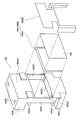
図8は、電気光学装置本体44Aの構造を示す斜視図である。なお、図8は、G色光およびR色光側から電気光学装置本体44Aを見た図であり、G色光およびR色光側と同様の構造となっているものとする。
電気光学装置本体44Aは、図8に示すように、3つの光変調装置440と、3つの射出側偏光板443(図7)と、各光変調装置440および各射出側偏光板443を支持する支持体445と、支持体445、光変調装置440、および射出側偏光板443の部材間に適宜介装される熱伝導性部材446と、クロスダイクロイックプリズム444と、このクロスダイクロイックプリズム444の上面に固定される台座447と、この台座447の上面に固定される放熱装置としての放熱部材448とを備える。
光変調装置440は、色分離光学装置42で分離され、入射側偏光板442(図7)を介した各色光を画像情報に応じて変調する3つの液晶パネル441R,441G,441B(赤色光用の液晶パネルを441R、緑色光用の液晶パネルを441G、青色光用の液晶パネルを441Bとする)と、これら液晶パネル441R,441G,441Bを保持する保持枠449とを備える。
[1-1-5. Structure of electro-optical device body]
FIG. 8 is a perspective view showing the structure of the electro-optical device
As shown in FIG. 8, the electro-optical device
The
液晶パネル441R,441G,441Bは、例えば、ポリシリコンTFT(Thin Film Transistor)をスイッチング素子として用いたものであり、対向配置される一対の透明基板内に液晶が密封封入されている。また、具体的な図示は省略するが、前記一対の透明基板の光束入射側および光束射出側の双方には、サファイア等からなる防塵ガラスが密着して貼り付けられている。そして、この防塵ガラスにより、前記一対の透明基板外面を被覆して塵埃の付着を防止する。
そして、この液晶パネル441R,441G,441Bは、入射側偏光板442を介して入射する光束を画像情報に応じて変調して射出する。
The
The
保持枠449は、図8に示すように、略中央部分に光束透過用の開口部449Aが形成された矩形状の枠体であり、内部にて各液晶パネル441R,441G,441Bを収納保持する。この保持枠449は、表面にブラックアルマイト処理が施されたアルミニウム合金等の熱伝導性部材から構成されている。
また、この保持枠449において、開口部449A周縁の四隅部分には、表裏を貫通する孔449Bが形成され、支持体445の後述するピンを挿通可能に構成されている。
なお、支持体445による光変調装置440の支持構造の詳細については、支持体445の構造を説明する際に、同時に説明する。
As shown in FIG. 8, the holding
Further, in this holding
Note that details of the support structure of the
射出側偏光板443は、入射側偏光板442と同様の構成を有し、液晶パネル441R,441G,441Bから射出された光束のうち、一定方向の偏光光のみ透過させ、その他の光束を吸収する。そして、上述した入射側偏光板442、液晶パネル441R,441G,441B、および射出側偏光板443によって、画像情報に応じて変調された光学像を形成する。
なお、支持体445による射出側偏光板443の支持構造の詳細については、支持体445の構造を説明する際に、同時に説明する。
クロスダイクロイックプリズム444は、各射出側偏光板443(図7)を介した光学像を合成してカラー画像を形成し、所定方向に射出するものであり、具体的な図示は省略するが、赤色光を反射する誘電体多層膜と、青色光を反射する誘電体多層膜とが、4つの直角プリズムの界面に沿って略X字状に設けられ、これらの誘電体多層膜により3つの色光が合成される。
The exit-side
Note that details of the support structure of the emission-side
The cross
図9および図10は、支持体445の構造、および支持体445による光変調装置440および射出側偏光板443の支持構造を示す分解斜視図である。具体的に、図9は、支持体445による光変調装置440の支持構造を光束入射側から見た分解斜視図である。また、図10は、支持体445による射出側偏光板443の支持構造を光束射出側から見た分解斜視図である。
支持体445は、表面にブラックアルマイト処理が施されたアルミニウム合金製の部材であり、図9および図10に示すように、略中央部分に光束透過用の開口部445A1を有する矩形板状体445Aと、矩形板状体445Aの上下端縁から略法線方向にそれぞれ突出する第1突出部445Bおよび第2突出部445Cとを備え、側面視略コ字状に形成されている。そして、この支持体445は、熱伝導性部材446を介して光変調装置440および射出側偏光板443を熱伝達可能に支持固定する。
9 and 10 are exploded perspective views showing the structure of the
The
矩形板状体445Aにおいて、その光束入射側端面には、図9に示すように、開口部445A1の周縁に、光変調装置440を構成する保持枠449の4つの孔449Bに対応して、法線方向に突出する4つのピン状部445A2が形成されている。そして、この4つのピン状部445A2は、光変調装置44の保持枠449に形成された4つの孔449Bに挿通され、熱伝導性の接着剤によりピン状部445A2の外周面と孔449Bの内周面とが接着固定されることで、光変調装置440が支持体445のコ字状内側に支持固定される。
また、光束射出側端面には、図10に示すように、開口部445A1の周縁に、厚み方向に窪み、射出側偏光板443を支持する凹部としての支持面445A3が形成されている。また、支持面445A3の上端縁略中央部分から支持体445の上方側にかけて、支持面445A3と略面一となる平面視略凸字状の凹部が形成され、この凹部は、熱伝導性部材446が貼り付けられる貼付面445A4とされる。
In the rectangular plate-
Further, as shown in FIG. 10, a
第1突出部445Bは、支持体445をクロスダイクロイックプリズム444の各光束入射端面に対向した状態で台座447に固定する部分であり、その上面には、図9および図10に示すように、固定用孔445B1が形成されている。
第2突出部445Cは、電気光学装置本体44A全体をライトガイド47の底面に固定する部分であり、図9に示すように、固定用孔445C1が形成されている。なお、第2突出部445Cは、電気光学装置本体44A全体をライトガイド47の底面に固定する機能の他、例えば、ヒートシンク等の放熱装置等の他の部材を支持固定する部材として機能させてもよい。
The first projecting
The second projecting
熱伝導性部材446は、端面に適宜接着剤が塗布された厚みの薄いシート状に形成され、光変調装置440および支持体445、射出側偏光板443および支持体445を熱伝達可能に接続する。この熱伝導性部材446は、例えば、グラファイトシート、熱伝導性両面テープ、熱伝導性シート、銅板等にて構成できる。そして、この熱伝導性部材446は、光変調装置440および支持体445を熱伝達可能に接続するパネル用熱伝導性部材446A(図9)と、射出側偏光板443および支持体445を熱伝達可能に接続する偏光板用熱伝導性部材446B(図10)とを備える。
The heat
なお、パネル用熱伝導性部材446Aおよび偏光板用熱伝導性部材446Bはそれぞれ、光変調装置440および支持体445、射出側偏光板443および支持体445を熱伝達可能に接続すればよく、その形状は特に限定されない。例えば、本実施形態では、パネル用熱伝導性部材446Aは、図9に示すように、平面視コ字形状のパネル用第1熱伝導性部材446A1と、平面視矩形形状のパネル用第2熱伝導性部材446A2とで構成される。そして、パネル用第1熱伝導性部材446A1およびパネル用第2熱伝導性部材446A2は、保持枠449内に液晶パネル441R,441G,441Bが収納された状態で、液晶パネル441R,441G,441Bの光束射出側に位置し保持枠449の開口部449Aから露出する図示しない防塵ガラスの端縁に沿って、該防塵ガラスに貼り付けられる。また、光変調装置440が支持体445のコ字状内側に配置された状態では、パネル用第1熱伝導性部材446A1のコ字状先端端縁が光束射出側に折り曲げられ、折り曲げられた部分が支持体445の矩形板状体445Aの側面に接着固定される。さらに、パネル用第2熱伝導性部材446A2の下方側が支持体445の第2突出部445Cの上面に沿って折り曲げられ、折り曲げられた部分が第2突出部445Cの上面に接着固定される。
The panel heat
また、偏光板用熱伝導性部材446Bは、図10に示すように、平面視コ字形状の偏光板用第1熱伝導性部材446B1と、下方側が平面視コ字形状となり、上側が支持体445の貼付面445A4に対応して平面視凸字形状となる偏光板用第2熱伝導性部材446B2とで構成されている。そして、偏光板用第1熱伝導性部材446B1は、射出側偏光板443と支持体445の支持面445A3との間に介装され、射出側偏光板443が支持体445の支持面445A3に熱伝達可能に接続する。また、偏光板用第2熱伝導性部材446B2は、射出側偏光板443が支持体445の支持面445A3に支持された状態で、射出側偏光板443の上端縁および左右端縁に沿って、下方側のコ字状部分が貼り付けられるとともに、下方側のコ字状先端端縁が光束入射側に折り曲げられ、折り曲げられた部分が支持体445の矩形板状体445Aの側面に接着固定される。さらに、偏光板用第2熱伝導性部材446B2の上方側の凸字状部分が支持体445の貼付面445A4に接着固定される。
Further, as shown in FIG. 10, the thermal conductive member for polarizing
台座447は、図8に示すように、平面視矩形形状を有するアルミニウム合金製の板体から構成され、クロスダイクロイックプリズム444の上面に固定される。この台座447は、クロスダイクロイックプリズム444および光変調装置440を平面的に覆うように配置される。すなわち、電気光学装置本体44Aを上方側から見た際、台座447により光変調装置440およびクロスダイクロイックプリズム444が隠れる。
また、台座447には、図示は省略するが、支持体445の固定用孔445B1に対応して、ねじ等の固定部材を挿通可能とする孔が形成されている。そして、前記孔を介してねじ等の固定部材を支持体445の固定用孔445B1に螺合固定することで、各支持体445がクロスダイクロイックプリズム444の各光束入射端面に対向するように台座447の下面に固定される。
また、この台座447は、電気光学装置本体44Aをライトガイド47に収納した際、ライトガイド47を構成する図示しない上ライトガイドの開口部分(電気光学装置本体44Aの上方側)を閉塞するように配置される。
As shown in FIG. 8, the
Although not shown, the
Further, the
放熱部材448は、アルミニウム合金等の熱伝導率の高い材料で形成され、矩形状の板体448Aと、板体446B1の上面から上方に向けて突出する複数のピン状部材448Bとが一体的に構成されたものである。このように複数のピン状部材448Bを設けることで、放熱部材448の表面積を大きくし、熱を放出しやすい構造となる。
なお、上述した保持枠449、支持体445、放熱部材448は、アルミニウム合金に限らず、熱伝導性を有する部材であればよく、例えば、インバーおよび42Ni−Fe等の鉄−ニッケル合金、マグネシウム合金、炭素鋼、黄銅、ステンレス等の金属、または、カーボンファイバー、カーボンナノチューブ等のカーボンフィラーを混入させた樹脂(ポリカーボネート、ポリフェニレンサルファイド、液晶樹脂等)等によって構成してもよい。また、保持枠449、支持体445、および放熱部材448を上述した同一の材料にて構成してもよく、異なる材料にて構成してもよい。
The
The holding
[1-2.冷却構造]
次に、プロジェクションテレビ10の内部の冷却構造を図面に基づいて説明する。
図11は、第1の冷却流路51を示す図である。具体的に、図11(A)は、プロジェクションテレビ10の側方から第1の冷却流路51を見た図であり、図11(B)は、プロジェクションテレビ10の正面側から第1の冷却流路51を見た図である。
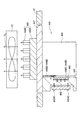
図12は、電気光学装置本体44Aの冷却構造を示す図である。なお、図12では、G色光側の冷却構造が示されているが、R,B色光側の冷却構造も同様のものとする。
図13は、第2の冷却流路53を示す図である。具体的に、図13(A)は、プロジェクションテレビ10の側方から第2の冷却流路53を見た図であり、図13(B)は、プロジェクションテレビ10の正面側から第2の冷却流路53を見た図である。
プロジェクションテレビ10の内部には、図11および図13に示すように、プロジェクションテレビ10を構成する電気光学装置本体44Aを主に冷却する第1の冷却流路51と、光源装置411を主に冷却する第2の冷却流路53とが形成されている。
[1-2. Cooling structure]
Next, the cooling structure inside the
FIG. 11 is a diagram showing the first
FIG. 12 is a diagram illustrating a cooling structure of the electro-optical device
FIG. 13 is a diagram showing the second cooling flow path 53. Specifically, FIG. 13A is a view of the second cooling flow channel 53 viewed from the side of the
As shown in FIGS. 11 and 13, the
第1の冷却流路51では、図12に示すように、電気光学装置本体44Aの上方に位置し、ダクト25の吸気側に設けられた冷却ファン52が用いられる。
この冷却ファン52は、空気の吸入方向と吸入した空気の吐出方向とが同一である軸流ファンで構成され、電気光学装置本体44Aの上方の空気を吸い込んで、ダクト25に向けて吐出する。そして、この冷却ファン52が駆動することにより、図11に示すように、電気光学装置本体44Aの上方の空気が吸い込まれ、吸い込まれた空気が下部キャビネット31の切り欠き371A1およびミラーケース12の切り欠き24Aを介してダクト25に吐出される。ダクト25に吐出された空気は、ミラーケース12の切り欠き24Bから流出し、ミラーケース12の側壁23、背面壁21、および側壁22に沿って流通し、再度、冷却ファン52に吸い込まれる。なお、図12に示すように、電気光学装置本体44Aの台座447は、電気光学装置本体44Aがライトガイド47内に収納保持された際、ライトガイド47の開口部分を閉塞するように配置されている。このため、ミラーケース12の側壁23、背面壁21、および側壁22に沿って流通し、再度、電気光学装置本体44Aの上方に戻る空気は、台座447により流路が規制され、すなわち、光変調装置440側に向かうことなく、冷却ファン52に吸い込まれる。このように冷却ファン52により、ミラーケース12およびスクリーン14等により形成される内部空間を循環する第1の冷却流路51が形成される。
As shown in FIG. 12, the first
The cooling
ところで、電気光学装置本体44Aにおいて、液晶パネル441R,441G,441Bは、光源装置411から照射される光束の一部を吸収するため、熱が生じる。また、射出側偏光板443も、所定の偏光軸を有する光束を透過し、他の偏光軸を有する光束を吸収するため、熱が生じる。
ここで、射出側偏光板443に生じた熱は、図12に示すように、偏光板用熱伝導性部材446Bを介して支持体445に伝達される。
また、液晶パネル441R,441G,441Bに生じた熱も略同様に、図12に示すように、保持枠449に伝達され、支持体445のピン状部445A2、および図12では図示しないパネル用熱伝導性部材446A(図9)を介して支持体445に伝達される。
そして、射出側偏光板443および液晶パネル441R,441G,441Bから支持体445に伝達された熱は、台座447を介して放熱部材448に伝達され、放熱部材448のピン状部材448Bを介して、第1の冷却流路51を流れる冷却空気により冷却される。
Meanwhile, in the electro-optical device
Here, as shown in FIG. 12, the heat generated in the emission
Similarly, the heat generated in the
The heat transmitted from the emission
第2の冷却流路53では、図13に示すように、光学ユニット40の光源装置411上に取り付けられる排気ファン54が用いられる。
この排気ファン54は、冷却ファン52と同様に軸流ファンで構成される。そして、この排気ファン54が駆動することで、図13に示すように、下部キャビネット31の側部パネル33に形成された吸気口331からプロジェクションテレビ10外部の空気が内部へと引き寄せられ、下部キャビネット31の設置部37に形成された孔372(図5)を介して光源装置411へと導入される。光源装置411に導入された空気は、排気ファン54により吸い込まれる過程で光源装置411の光源ランプ416およびリフレクタ417を冷却する。排気ファン54に吸い込まれた空気は、ダクト26に吐出され、ダクト26およびダクト55を介して下部キャビネット31の側部パネル33に形成された排気口341からプロジェクションテレビ10外部へと排出される。
In the second cooling flow path 53, as shown in FIG. 13, an
The
以上、説明した第1の冷却流路51および第2の冷却流路53は、互いに交差しないように設定されている。具体的に、光学ユニット40において、光源装置411と電気光学装置本体44Aとの間に介装されるインテグレータ照明光学系41、色分離光学装置42、およびリレー光学系43等がライトガイド47内に収納されているため、ライトガイド47内で電気光学装置本体44Aから光源装置411、または光源装置411から電気光学装置本体44Aへと空気が流通することがない。また、ライトガイド47外においても、下部キャビネット31の設置部37により、光源装置411側と電気光学装置本体44A側とが仕切られた構成となっており、電気光学装置本体44A側から光源装置411側、または光源装置411側から電気光学装置本体44A側へと空気が流通することがない。
なお、上述した第1の冷却流路51は、プロジェクションテレビ10外部と通じることのない密閉された空間内の流路として説明したが、本発明では、第1の冷却流路51は、プロジェクションテレビ10外部の空気と通じる流路となる構成としても構わない。また、第1の冷却流路51および第2の冷却流路53も同様に、本発明では、互いに交差する、すなわち、互いに空気が流通可能となる構成として構わない。
The
In addition, although the 1st
[1-3.第1実施形態の効果]
上述した第1実施形態によれば、以下の効果がある。
(1)光学ユニット40は、光変調装置440と、クロスダイクロイックプリズム444と、ライトガイド47と、アルミニウム合金からなる台座447および支持体445と、放熱部材448とを備えている。光変調装置440は、液晶パネル441R,441G,441Bがアルミニウム合金からなる保持枠449に保持され、保持枠449が支持体445に熱伝達可能に支持される。また、支持体445は、台座447に熱伝達可能に支持固定される。さらに、台座447は、放熱部材448と熱伝達可能に接続する。このことにより、光源装置411からの光束が照射されることにより液晶パネル441R,441G,441Bに生じる熱を、液晶パネル441R,441G,441B〜保持枠449〜支持体445〜台座447〜放熱部材448の熱伝達経路にしたがって逃がすことができる。したがって、例えば、冷却ファン52により光変調装置440に直接、冷却空気を送風しなくても液晶パネル441R,441G,441Bの冷却効率の向上を図れる。
[1-3. Effects of the first embodiment]
The first embodiment described above has the following effects.
(1) The
(2)台座447は、クロスダイクロイックプリズム444および光変調装置440を平面的に覆うように配置されるとともに、電気光学装置本体44Aがライトガイド47に収納保持された際にライトガイド47の開口部分を閉塞するように配置されるので、第1の冷却流路51にしたがって流れる空気が光変調装置440側に向かうことがない。したがって、ライトガイド47における電気光学装置本体44Aの設置位置近傍において、ライトガイド47の内部が略密閉空間となり、ライトガイド47外部から光変調装置440へと空気の流れにしたがって塵埃がライトガイド47内部に入り込むことを回避でき、光変調装置440の液晶パネル441R,441G,441Bに塵埃が付着することを防止できる。
(2) The
(3)支持体445の矩形板状体445Aの光束射出端面には、厚み方向に窪む支持面445A3が形成されている。そして、射出側偏光板443は、支持体445の支持面445A3に熱伝達可能に貼り付けられている。このことにより、光束の照射により射出側偏光板443に生じる熱を、射出側偏光板443〜支持体445〜台座447〜放熱部材448の熱伝達経路にしたがって逃がすことができ、射出側偏光板443の熱劣化を回避できる。したがって、例えば、冷却ファン52による強制冷却によらずとも、上記熱伝達経路により射出側偏光板443も冷却できる。
(4)射出側偏光板443が支持体445に貼り付けられると、該射出側偏光板443も台座447により平面的に覆われるので、光変調装置440と同様に、射出側偏光板443にも塵埃が付着することを回避できる。
(3) A support surface 445A3 that is recessed in the thickness direction is formed on the light beam exit end surface of the rectangular plate-
(4) When the emission-side
(5)支持体445は、矩形板状体445A、第1突出部445B、および第2突出部445Cで構成され、第1突出部445Bが台座447に熱伝達可能に支持固定されるので、例えば、支持体445が板状に形成され、板状端縁にて台座447に支持固定される構成と比較して、支持体445と台座447との接触面積を大きくでき、支持体445〜台座447の熱伝達経路における熱の伝達効率を向上でき、液晶パネル441R,441G,441Bおよび射出側偏光板443の放熱効率をさらに向上できる。
(6)支持体445の第2突出部445Cは、電気光学装置本体44Aをライトガイド47に固定するための固定部として機能するので、電気光学装置本体44Aをライトガイド47に固定するための部材を省略でき、光学ユニット40の小型化および製造コストの低減を図れる。
(5) The
(6) The second projecting
(7)光変調装置440を構成する保持枠449には、4つの孔449Bが形成され、支持体445の矩形板状体445Aには、保持枠449の孔449Bに対応して4つのピン状部445A2が形成されているので、保持枠449の孔449Bにピン状部445A2を挿通させるように光変調装置440を支持体445に設置することで、光変調装置440の支持体445への取り付けを容易に実施でき、光学ユニット40の組み立て作業を容易に実施できる。また、光変調装置440と支持体445の矩形板状体445Aとの間の隙間に、例えば、ドライバ等の先端を挿入することで、支持体445から光変調装置440を容易に取り外すことができ、光変調装置440のリワーク性も向上する。
(7) The holding
(8)支持体445および光変調装置440の保持枠449は、表面にブラックアルマイト処理が施されているので、液晶パネル441R,441G,441Bおよび射出側偏光板443から伝達された熱を、台座447等へと伝達するとともに、支持体445および保持枠449の表面から空気中に放射することができる。したがって、液晶パネル441R,441G,441Bおよび射出側偏光板443の冷却効率の向上をさらに図れる。
(8) Since the
(9)電気光学装置本体44Aは、熱伝導性部材446を備える。そして、熱伝導性部材446を構成するパネル用熱伝導性部材446Aのパネル用第1熱伝導性部材446A1およびパネル用第2熱伝導性部材446A2は、液晶パネル441R,441G,441Bの光束射出側に位置する防塵ガラスに貼り付けられるとともに、支持体445に貼り付けられ、液晶パネル441R,441G,441Bおよび支持体445を熱伝達可能に接続する。このことにより、液晶パネル441R,441G,441B〜保持枠449の熱伝達経路の他、液晶パネル441R,441G,441B〜パネル用熱伝導性部材446A〜支持体445の他の熱伝達経路を確保でき、液晶パネル441R,441G,441Bの冷却効率をさらに向上させることができる。
(9) The electro-optical device
(10)熱伝導性部材446を構成する偏光板用熱伝導性部材446Bの偏光板用第1熱伝導性部材446B1は、射出側偏光板443と支持体445の支持面445A3との間に介装され、射出側偏光板443と支持体445とを熱伝達可能に接着固定する。このことにより、射出側偏光板443〜支持体445の熱伝達経路における熱抵抗を小さくでき、射出側偏光板443の放熱効率をさらに向上できる。
(11)偏光板用熱伝導性部材446Bの偏光板用第2熱伝導性部材446B2は、支持体445の支持面445A3に貼り付けられた射出側偏光板443の光束射出側端面と支持体445の矩形板状体445Aの光束射出端面とを熱伝達可能に接続する。このことにより、射出側偏光板443の光束入射側端面から支持体445に熱伝達される経路の他、射出側偏光板443の光束射出側端面から支持体445に熱伝達される経路を確保でき、射出側偏光板443の放熱効率をさらに一層向上できる。
(10) The first heat conductive member for polarizing plate 446B1 of the heat conductive member for polarizing
(11) The second heat conductive member 446B2 for the polarizing plate of the heat
(12)支持体445の矩形板状体445Aの光束射出側端面には、偏光板用熱伝導性部材446Bの偏光板用第2熱伝導性部材446B2を貼り付けるための貼付面445A4が形成されているので、偏光板用第2熱伝導性部材446B2を射出側偏光板443の光束射出側端面に貼り付けるとともに、貼付面445A4に貼り付けることで、偏光板用第2熱伝導性部材446B2と支持体445との接触面積を大きくでき、射出側偏光板443〜支持体445の熱伝達経路における熱の伝達経路をさらに向上でき、射出側偏光板443の放熱効率をさらに一層向上できる。
(12) A sticking surface 445A4 for sticking the second heat conductive member for polarizing plate 446B2 of the heat conductive member for polarizing
(13)プロジェクションテレビ10は、液晶パネル441R,441G,441B等の光学素子に塵埃等が付着することを防止できる光学ユニット40を備えているので、付着した塵埃等が投射画像上に表示陰として映りこむことを回避でき、常に鮮明な投射画像を表示できる。
(14)プロジェクションテレビ10は、上述した光学ユニット40と、この光学ユニット40の電気光学装置本体44Aを冷却する冷却ファン52を備えているので、上述した電気光学装置本体44Aにおける熱伝達経路による放熱構造と、冷却ファン52とを併用することで、電気光学装置本体44Aの冷却効率をさらに向上できる。
(15)電気光学装置本体44Aは、上述した熱伝達経路にしたがって放熱することができるため、冷却ファン52の送風量をそれほど高くする必要がなく、冷却ファン52を併用した場合であっても、プロジェクションテレビ10の静粛性を十分に確保できる。また、冷却ファン52の送風量をそれほど高くする必要がないので、冷却ファン52の小型化を図れ、プロジェクションテレビ10を大型化することがない。
(13) Since the
(14) Since the
(15) Since the electro-optical device
[2.第2実施形態]
次に、本発明の第2実施形態を図面に基づいて説明する。
以下の説明では、前記第1実施形態と同様の構造および同一部材には同一符号を付して、その詳細な説明は省略または簡略化する。
前記第1実施形態では、電気光学装置44は、入射側偏光板442以外の、光変調装置440、射出側偏光板443、クロスダイクロイックプリズム444、支持体445、熱伝導性部材446、台座447、および放熱部材448が一体化されて電気光学装置本体44Aを構成している。
これに対して第2実施形態では、電気光学装置44Bは、電気光学装置本体44Aと入射側偏光板442とが一体化した構成を有している。
[2. Second Embodiment]
Next, 2nd Embodiment of this invention is described based on drawing.
In the following description, the same structure and the same members as those in the first embodiment are denoted by the same reference numerals, and detailed description thereof is omitted or simplified.
In the first embodiment, the electro-
On the other hand, in the second embodiment, the electro-
[2-1.電気光学装置の構造]
図14は、第2実施形態における電気光学装置44Bの構造を示す図である。なお、図14では、G色光側の構造のみが示されているが、R,B色光側の構造も同様のものとする。
電気光学装置44Bは、図14に示すように、第1実施形態で説明した光変調装置440、入射側偏光板442、射出側偏光板443、クロスダイクロイックプリズム444、支持体445、熱伝導性部材446、台座447、および放熱部材448の他、入射側光学変換素子支持枠としての入射側偏光板支持枠450と、入射側偏光板用熱伝導性部材446Cとを備える。そして、これら各部材440,442〜448,446C,450が一体的にユニット化されている。
入射側偏光板支持枠450は、略中央部分に光束透過用の図示しない開口を有し、表面にブラックアルマイト処理が施されたアルミニウム合金製の矩形板状体で構成され、支持体445の第1突出部445Bの先端に図示しないねじ等により熱伝達可能に取り付けられる。
入射側偏光板用熱伝導性部材446Cは、第1実施形態で説明した熱伝導性部材446と同様の材料にて構成され、略中央部分に光束透過用の図示しない開口を有する矩形枠状に形成されている。そして、この入射側偏光板用熱伝導性部材446Cは、入射側偏光板442の光束射出側端面の端縁に沿って貼り付けられるとともに、入射側偏光板用熱伝導性部材446Cの図示しない開口周縁に接着固定され、入射側偏光板442を入射側偏光板支持枠450に熱伝達可能に接着固定する。
[2-1. Structure of electro-optical device]
FIG. 14 is a diagram illustrating the structure of the electro-
As shown in FIG. 14, the electro-
The incident-side polarizing
The incident-side polarizing plate heat
[2-2.第2実施形態の効果]
上述した第2実施形態によれば、上記(1)〜(15)の他、以下の効果がある。
(16)入射側偏光板442は、アルミニウム合金製の入射側偏光板支持枠450により熱伝達可能に支持固定される。そして、入射側偏光板支持枠450は、支持体445の第1突出部445Bの先端に熱伝達可能に取り付けられる。このことにより、光束の照射により入射側偏光板442に生じる熱を、入射側偏光板442〜入射側偏光板支持枠450〜支持体445〜台座447〜放熱部材448の熱伝達経路にしたがって逃がすことができ、入射側偏光板442の熱劣化を回避できる。したがって、例えば、入射側偏光板442に冷却空気を送風して該入射側偏光板442の強制冷却を実施しなくても、上記熱伝達経路により入射側偏光板442も冷却できる。
[2-2. Effects of the second embodiment]
According to 2nd Embodiment mentioned above, there exist the following effects other than said (1)-(15).
(16) The incident-side
(17)入射側偏光板442を入射側偏光板支持枠450により光変調装置440の光束入射側に配置することで、光変調装置440の液晶パネル441R,441G,441Bへの塵埃の付着をさらに防止できる。
(18)入射側偏光板442も台座447により平面的に覆われる構成であるので、光変調装置440および射出側偏光板443と同様に、入射側偏光板442にも塵埃が付着することを回避できる。
(17) By disposing the incident
(18) Since the incident-side
[3.第3実施形態]
次に、本発明の第3実施形態を図面に基づいて説明する。
以下の説明では、前記第1実施形態と同様の構造および同一部材には同一符号を付して、その詳細な説明は省略または簡略化する。
前記第1実施形態では、放熱装置として放熱部材448を採用している。
これに対して第2実施形態では、放熱装置として、放熱部材448の他、ペルチェモジュール448Cを採用している。すなわち、前記第1実施形態に対して放熱装置の構成が異なるのみである。
[3. Third Embodiment]
Next, 3rd Embodiment of this invention is described based on drawing.
In the following description, the same structure and the same members as those in the first embodiment are denoted by the same reference numerals, and detailed description thereof is omitted or simplified.
In the first embodiment, the
On the other hand, in 2nd Embodiment, the
[3-1.電気光学装置本体の構造]
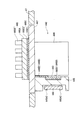
図15は、第3実施形態における電気光学装置本体44Cの構造を示す図である。なお、図15では、G色光側の構造のみが示されているが、R,B色光側の構造も同様のものとする。
電気光学装置本体44Cは、図15に示すように、第1実施形態で説明した光変調装置440、射出側偏光板443、クロスダイクロイックプリズム444、支持体445、熱伝導性部材446、台座447、および放熱部材448の他、ペルチェモジュール448Cを備える。そして、これら各部材440,443〜448,448Cが一体的にユニット化されている。
ペルチェモジュール448Cは、具体的な図示は省略するが、p型半導体とn型半導体とを金属片で接合して構成した接合対を複数有しており、これら複数の接合対は電気的に直列に接続され、図示しない制御基板に実装されたCPU(Central Processing Unit)等の演算処理装置による制御の下、n型半導体からp型半導体へ、またはp型半導体からn型半導体へと直流電流が流れる。
ここで、n型半導体からp型半導体へ直流電流を流すと、金属片が冷却されて周囲から熱を奪うことができるようになる。逆にp型半導体からn型半導体へ直流電流を流すと、金属片が加熱され、周囲に熱を放出することができるようになる。
[3-1. Structure of electro-optical device body]
FIG. 15 is a diagram illustrating a structure of an electro-optical device
As shown in FIG. 15, the electro-optical device
Although not specifically shown, the
Here, when a direct current is passed from the n-type semiconductor to the p-type semiconductor, the metal piece is cooled and heat can be taken away from the surroundings. On the contrary, when a direct current is passed from the p-type semiconductor to the n-type semiconductor, the metal piece is heated, and heat can be released to the surroundings.
このような構成を有するペルチェモジュール448Cにおいて、直流電流を流すと、ペルチェモジュール448Cの一方の面が熱を吸収する吸熱部分となり、他方の面が熱を発生する発熱部分となる。なお、電流の向きを変えることによって吸熱部分と発熱部分との切換が可能となる。
本実施形態では、ペルチェモジュール448Cに流す直流電流は、一方向に固定され、ペルチェモジュール448Cにおける吸熱部分448C1および発熱部分448C2の箇所が固定されている。そして、ペルチェモジュール448Cの吸熱部分448C1は、図15に示すように、台座447の上面に直接接続する。また、ペルチェモジュール448Cの発熱部分448C2は、放熱部材448の板体448Aの下面に接続する。
そして、ペルチェモジュール448Cは、図示しない制御基板に実装されたCPU等の演算処理装置による制御の下、直流電流が流れることにより、台座447に伝達された熱を吸熱部分448C1により吸収するとともに、発熱部分448C2で放熱部材448に放出する。放熱部材448に伝達された熱は、ピン状部材448Bを介して、第1の冷却流路51を流れる冷却空気により冷却される。
In the
In the present embodiment, the direct current flowing through the
The
[3-2.第3実施形態の効果]
上述した第3実施形態によれば、上記(1)〜(15)の他、以下の効果がある。
(19)電気光学装置本体44Cは、ペルチェモジュール448Cを備えることにより、冷却空気を利用しないで台座447の強制冷却を実施できるので、第1実施形態で説明した台座447〜放熱部材448の熱伝達経路にしたがう自然熱伝達の構造と比較して、液晶パネル441R,441G,441Bおよび射出側偏光板443の冷却効率をさらに一層向上させることができる。
[3-2. Effects of the third embodiment]
According to 3rd Embodiment mentioned above, there exist the following effects other than said (1)-(15).
(19) Since the electro-optical device
[4.実施形態の変形]
以上、本発明について好適な実施形態を挙げて説明したが、本発明は、この実施形態に限定されるものではなく、本発明の要旨を逸脱しない範囲において種々の改良並びに設計の変更が可能である。
前記各実施形態では、プロジェクションテレビ10内に冷却ファン52による第1の冷却流路51が形成され、電気光学装置本体44A,44Cおよび電気光学装置44Bの放熱部材448が強制冷却されていたが、冷却ファン52を省略した構成も本発明に含まれるものである。また、冷却ファン52を採用する場合、その位置は、前記実施形態で説明した位置に限らず、電気光学装置本体44A,44Cおよび電気光学装置44Bを構成する放熱部材448の側方に配置し、該放熱部材448に冷却空気を送風、または該放熱部材448近傍の空気を吸入する構成としてもよい。
[4. Modification of Embodiment]
The present invention has been described with reference to a preferred embodiment. However, the present invention is not limited to this embodiment, and various improvements and design changes can be made without departing from the scope of the present invention. is there.
In each of the above embodiments, the first
前記各実施形態では、台座447は、クロスダイクロイックプリズム444の上面にのみ取り付けられていたが、これに限らず、クロスダイクロイックプリズム444の下面に取り付ける構成、上面および下面の双方に取り付ける構成を採用してもよい。台座447をクロスダイクロイックプリズム444の下面に取り付ける構成では、台座447に放熱部材448を熱伝達可能に接続し、この放熱部材448を、例えば、第2の冷却流路53を流れる流路内に設置すれば、放熱部材448の強制冷却を実施できる。また、この構成において、クロスダイクロイックプリズム444の上面および下面にそれぞれ台座447および放熱部材448を取り付ければ、電気光学装置本体44A,44Cおよび電気光学装置44Bの冷却効率をさらに向上させることができる。
前記各実施形態では、台座447は、ライトガイド47を構成する図示しない上ライトガイドの開口部分を閉塞する形状を有していたが、これに限らない。例えば、ライトガイド47を容器状に形成し、台座447にてライトガイド47の開口部分全体を閉塞する形状を有する構成としてもよい。
In each of the above-described embodiments, the
In each of the above embodiments, the
前記第1実施形態および前記第2実施形態では、放熱装置として、放熱部材448を採用した構成を説明し、前記第3実施形態では、放熱装置として、放熱部材448およびペルチェモジュール448Cを採用した構成を説明したが、放熱装置はこれに限らない。例えば、液冷ジャケット、ヒートパイプ等の放熱装置を採用した構成としてもよい。また、液冷ジャケット、ヒートパイプ等の放熱装置と、放熱部材448および/またはペルチェモジュール448Cとを組み合わせた構成としてもよい。例えば、液冷ジャケットまたはヒートパイプ等により台座447の熱をプロジェクションテレビ10内の空きスペースまで導き、該空きスペースにおいて放熱部材448および/またはペルチェモジュール448Cにより放熱させる構成とすることもできる。このような構成では、プロジェクションテレビ10の設計の自由度が高まるとともに、放熱装置を含む電気光学装置本体44A,44Cおよび電気光学装置44Bがプロジェクションテレビ10の小型化の障害となることを回避でき、プロジェクションテレビ10の小型化が図りやすくなる。また、このような構成では、空きスペースに配置される放熱部材448および/またはペルチェモジュール448Cに、例えば、第2の冷却流路53にて用いられる排気ファン54により空気を送風する構成とすれば、冷却効率をさらに高めることができる。また、排気ファン54を電気光学装置本体44A,44Cおよび電気光学装置44Bの冷却にも寄与させることができ、ファンの数量を削減することが可能となる。
前記各実施形態では、放熱装置の放熱部として、複数のピン状部材448Bを採用した構成を説明したが、ピン状に限らない。放熱装置の表面積を大きくできる形状であればよく、例えば、板体448A上面に略直交するように複数の板状体が並列配置されている構造を採用してもよい。
In the first embodiment and the second embodiment, a configuration in which the
In each of the above-described embodiments, the configuration in which the plurality of pin-
前記第1実施形態および前記第3実施形態では、射出側光学変換素子として射出側偏光板443を採用し、前記第2実施形態では、入射側光学変換素子として入射側偏光板442を採用していたが、これに限らない。入射側光学変換素子および射出側光学変換素子として、例えば、位相差板または視野角補正板等を採用してもよい。
前記第2実施形態では、入射側偏光板支持枠450は、支持体445の第1突出部445Bの先端に取り付けられていたが、これに限らず、台座447の下面に熱伝達可能に取り付ける構成を採用してもよい。
In the first embodiment and the third embodiment, the exit
In the second embodiment, the incident-side polarizing
前記各実施形態では、パネル用熱伝導性部材446Aは、液晶パネル441R,441G,441Bと支持体445とを熱伝達可能に接続していたが、これに限らず、保持枠449と支持体445とを熱伝達可能に接続してもよい。
前記各実施形態では、3つの光変調装置440を用いたプロジェクションテレビ10の例のみを挙げたが、本発明は、1つの光変調装置のみを用いたプロジェクションテレビ、2つの光変調装置を用いたプロジェクションテレビ、あるいは、4つ以上の光変調装置を用いたプロジェクションテレビにも適用可能である。
前記各実施形態では、光学ユニット40をリアプロジェクタとしてのプロジェクションテレビ10に搭載した構成を説明したが、本発明は、フロント投射型のプロジェクタにも適用可能である。
In each of the above-described embodiments, the panel heat
In each of the above embodiments, only the example of the
In each of the above embodiments, the configuration in which the
本発明を実施するための最良の構成などは、以上の記載で開示されているが、本発明は、これに限定されるものではない。すなわち、本発明は、主に特定の実施形態に関して特に図示され、かつ、説明されているが、本発明の技術的思想および目的の範囲から逸脱することなく、以上述べた実施形態に対し、形状、材質、数量、その他の詳細な構成において、当業者が様々な変形を加えることができるものである。
したがって、上記に開示した形状、材質などを限定した記載は、本発明の理解を容易にするために例示的に記載したものであり、本発明を限定するものではないから、それらの形状、材質などの限定の一部若しくは全部の限定を外した部材の名称での記載は、本発明に含まれるものである。
Although the best configuration for carrying out the present invention has been disclosed in the above description, the present invention is not limited to this. That is, the invention has been illustrated and described primarily with respect to particular embodiments, but may be configured for the above-described embodiments without departing from the scope and spirit of the invention. Various modifications can be made by those skilled in the art in terms of materials, quantity, and other detailed configurations.
Therefore, the description limited to the shape, material, etc. disclosed above is an example for easy understanding of the present invention, and does not limit the present invention. The description by the name of the member which remove | excluded the limitation of one part or all of such is included in this invention.
本発明の光学装置は、光変調装置等の光学素子に直接、冷却空気を送風しなくても冷却効率の向上を図れるとともに、塵埃付着を防止できるため、リアプロジェクタに用いられる光学装置として有用である。 The optical device of the present invention is useful as an optical device used for a rear projector because it can improve cooling efficiency and prevent dust from adhering without blowing cooling air directly to an optical element such as a light modulator. is there.
10・・・プロジェクションテレビ(リアプロジェクタ)、11・・・上部キャビネット(筐体)、14・・・スクリーン(透過型スクリーン)、31・・・下部キャビネット(筐体)、42・・・色分離光学装置、46・・・投射レンズ(投射光学装置)、47・・・ライトガイド(光学部品用筐体)、411・・・光源装置、440・・・光変調装置、441R,441G,441B・・・液晶パネル(光変調素子)、442・・・入射側偏光板(入射側光学変換素子)、443・・・射出側偏光板(射出側光学変換素子)、444・・・クロスダイクロイックプリズム(色合成光学装置)、445・・・支持体、445A・・・矩形板状体、445A1・・・開口部、445A2・・・ピン状部、445A3・・・支持面(凹部)、445B・・・第1突出部、445C・・・第2突出部、446・・・熱伝導性部材、447・・・台座、448・・・放熱部材(放熱装置)、448C・・・ペルチェモジュール(放熱装置)、449・・・保持枠、449A・・・開口部、449B・・・孔、450・・・入射側偏光板支持枠(入射側光学変換素子支持枠)。
DESCRIPTION OF
Claims (9)
前記光変調装置は、光変調を実施する光変調素子と、略中央部分に光束透過用の開口部を有し、前記光変調素子を保持する熱伝導性材料からなる保持枠とを備え、
前記色合成光学装置の光束入射端面に交差する端面のうちの少なくとも1またはいずれかの端面に固定され、前記色合成光学装置および前記光変調装置を平面的に覆うように配置される熱伝導性材料からなる台座と、
前記台座と熱伝達可能に接続され、前記台座の熱を放熱する放熱装置と、
前記台座に熱伝達可能に支持固定されるとともに、前記光変調装置が前記色合成光学装置の光束入射端面に対向するように前記光変調装置の保持枠を熱伝達可能に支持する熱伝導性材料からなる支持体とを備え、
前記台座は、前記光変調装置および前記色合成光学装置が前記光学部品用筐体内部の所定位置に収納保持された際に前記光学部品用筐体外部から前記光変調装置への空気の流れを規制することを特徴とする光学装置。 Color synthesizing optics having a light modulation device that modulates a plurality of color lights according to image information, a light beam incident end surface facing the light modulation device, and a light beam emission end surface that synthesizes and emits the color light incident on the light beam incident end surface An optical device comprising: a device; and an optical component housing that houses and holds the light modulation device and the color synthesis optical device in a predetermined position inside the device,
The light modulation device includes a light modulation element that performs light modulation, and a holding frame made of a thermally conductive material that has an opening for transmitting a light beam at a substantially central portion and holds the light modulation element,
Thermal conductivity fixed to at least one or any of the end faces intersecting with the light beam incident end face of the color synthesizing optical device and arranged to cover the color synthesizing optical device and the light modulation device in a plane. A pedestal made of materials,
A heat radiating device connected to the pedestal so as to be capable of transferring heat, and radiating heat of the pedestal;
A heat conductive material that is supported and fixed to the pedestal so that heat can be transferred, and that supports the holding frame of the light modulation device so that the light modulation device faces a light beam incident end face of the color synthesis optical device. And a support made of
The pedestal allows air to flow from the outside of the optical component housing to the light modulation device when the light modulation device and the color combining optical device are stored and held in a predetermined position inside the optical component housing. An optical device characterized by regulating.
前記支持体の光束射出端面には、光束入射側に窪む凹部が形成され、
前記光変調装置および前記色合成光学装置の間に介装され、前記光変調装置から射出される光束を光学的に変換する射出側光学変換素子を備え、
前記射出側光学変換素子は、前記支持体の凹部に熱伝達可能に支持固定されることを特徴とする光学装置。 The optical device according to claim 1.
A concave portion recessed on the light beam incident side is formed on the light beam emission end surface of the support,
An emission-side optical conversion element that is interposed between the light modulation device and the color synthesis optical device and optically converts a light beam emitted from the light modulation device;
The optical apparatus according to claim 1, wherein the emission side optical conversion element is supported and fixed to the concave portion of the support body so that heat can be transferred.
前記光変調装置の光束入射側に配置され、入射する光束を光学的に変換する入射側光学変換素子と、光束透過用の開口部が形成され、前記入射側光学変換素子を熱伝達可能に支持する熱伝導性材料からなる入射側光学変換素子支持枠とを備え、
前記入射側光学変換素子支持枠は、前記支持体または前記台座に熱伝達可能に支持固定されることを特徴とする光学装置。 The optical device according to claim 1 or 2,
An incident side optical conversion element that optically converts an incident light beam and an opening for transmitting the light beam are formed on the light beam incident side of the light modulation device, and support the incident side optical conversion element so that heat can be transferred. An incident side optical conversion element support frame made of a thermally conductive material
The optical device, wherein the incident side optical conversion element support frame is supported and fixed to the support or the pedestal so that heat can be transferred.
前記支持体は、略中央部分に光束透過用の開口部が形成された矩形板状体と、前記矩形板状体の端縁の少なくとも1つの端縁から前記矩形板状体の略法線方向に突出する突出部とで構成され、前記突出部が前記台座に熱伝達可能に支持固定されることを特徴とする光学装置。 The optical device according to any one of claims 1 to 3,
The support includes a rectangular plate-like body having an opening for transmitting a light beam in a substantially central portion, and a substantially normal direction of the rectangular plate-like body from at least one edge of the rectangular plate-like body. An optical device characterized in that the protrusion is supported and fixed to the pedestal so that heat can be transferred.
前記光変調装置の保持枠には、前記開口部周縁に少なくとも2つの孔が形成され、
前記支持体の矩形板状体には、前記保持枠の孔に対応して光束入射側に突出する少なくとも2つのピン状部が形成されていることを特徴とする光学装置。 The optical device according to claim 4.
The holding frame of the light modulation device is formed with at least two holes on the periphery of the opening,
The optical device according to claim 1, wherein the rectangular plate-like body of the support is formed with at least two pin-like portions protruding toward the light beam incident side corresponding to the holes of the holding frame.
前記支持体および/または前記光変調装置の保持枠には、熱放射率を高める表面処理が施されていることを特徴とする光学装置。 The optical device according to any one of claims 1 to 5,
An optical device, wherein the support and / or the holding frame of the light modulation device is subjected to a surface treatment for increasing a heat emissivity.
前記光変調装置と前記支持体、前記光変調装置および前記色合成光学装置の間に介装される射出側光学変換素子と前記支持体、および、前記光変調装置の光束入射側に配置される入射側光学変換素子と前記入射側光学変換素子を支持する入射側光学変換素子支持枠の少なくともいずれかは、熱伝導性部材を介して熱伝達可能に接続されていることを特徴とする光学装置。 The optical device according to any one of claims 1 to 6,
Arranged between the light modulation device and the support, the light modulation device and the color synthesizing optical device, the exit-side optical conversion element and the support, and the light modulation device on the light beam incident side At least one of the incident side optical conversion element and the incident side optical conversion element support frame that supports the incident side optical conversion element is connected to be able to transfer heat through a heat conductive member. .
前記光学装置を冷却する冷却ファンを備え、
前記冷却ファンは、前記光学装置を構成する放熱装置の放熱部に冷却空気を送風、または前記放熱部近傍の空気を吸入することを特徴とするリアプロジェクタ。 The rear projector according to claim 8, wherein
A cooling fan for cooling the optical device;
The rear projector, wherein the cooling fan blows cooling air to a heat radiating portion of a heat radiating device constituting the optical device or sucks air in the vicinity of the heat radiating portion.
Priority Applications (1)
| Application Number | Priority Date | Filing Date | Title |
|---|---|---|---|
| JP2003348609A JP2005114997A (en) | 2003-10-07 | 2003-10-07 | Optical device and rear projector |
Applications Claiming Priority (1)
| Application Number | Priority Date | Filing Date | Title |
|---|---|---|---|
| JP2003348609A JP2005114997A (en) | 2003-10-07 | 2003-10-07 | Optical device and rear projector |
Publications (1)
| Publication Number | Publication Date |
|---|---|
| JP2005114997A true JP2005114997A (en) | 2005-04-28 |
Family
ID=34540758
Family Applications (1)
| Application Number | Title | Priority Date | Filing Date |
|---|---|---|---|
| JP2003348609A Withdrawn JP2005114997A (en) | 2003-10-07 | 2003-10-07 | Optical device and rear projector |
Country Status (1)
| Country | Link |
|---|---|
| JP (1) | JP2005114997A (en) |
Cited By (5)
| Publication number | Priority date | Publication date | Assignee | Title |
|---|---|---|---|---|
| JP2008256763A (en) * | 2007-04-02 | 2008-10-23 | Mitsubishi Electric Corp | Rear projection |
| JP2013024557A (en) * | 2011-07-14 | 2013-02-04 | Hamamatsu Photonics Kk | Electron beam irradiation device |
| US9664987B2 (en) | 2014-11-18 | 2017-05-30 | Canon Kabushiki Kaisha | Image display apparatus |
| KR20220109060A (en) * | 2021-01-28 | 2022-08-04 | (주)퀀텀테크 | Prism unit and liquid chemical concentration measurement device using this |
| JP2024023093A (en) * | 2022-08-08 | 2024-02-21 | セイコーエプソン株式会社 | Transparent optical element module and electronic equipment |
-
2003
- 2003-10-07 JP JP2003348609A patent/JP2005114997A/en not_active Withdrawn
Cited By (7)
| Publication number | Priority date | Publication date | Assignee | Title |
|---|---|---|---|---|
| JP2008256763A (en) * | 2007-04-02 | 2008-10-23 | Mitsubishi Electric Corp | Rear projection |
| JP2013024557A (en) * | 2011-07-14 | 2013-02-04 | Hamamatsu Photonics Kk | Electron beam irradiation device |
| US9664987B2 (en) | 2014-11-18 | 2017-05-30 | Canon Kabushiki Kaisha | Image display apparatus |
| KR20220109060A (en) * | 2021-01-28 | 2022-08-04 | (주)퀀텀테크 | Prism unit and liquid chemical concentration measurement device using this |
| KR102544841B1 (en) * | 2021-01-28 | 2023-06-20 | (주)퀀텀테크 | Prism unit and liquid chemical concentration measurement device using this |
| JP2024023093A (en) * | 2022-08-08 | 2024-02-21 | セイコーエプソン株式会社 | Transparent optical element module and electronic equipment |
| JP7574832B2 (en) | 2022-08-08 | 2024-10-29 | セイコーエプソン株式会社 | Light-transmitting optical element module and electronic device |
Similar Documents
| Publication | Publication Date | Title |
|---|---|---|
| TWI243272B (en) | Optical device, optical unit and projector | |
| TW403854B (en) | Projection type display device | |
| US6966653B2 (en) | Cooling device and optical device and projector having the cooling device | |
| CN100395656C (en) | Optical device and rear projector | |
| JP3969449B2 (en) | Optical component housing and projector | |
| JP2005121250A (en) | Cooling device and rear projector | |
| JP2005338236A (en) | projector | |
| JP2005114997A (en) | Optical device and rear projector | |
| JP2007041414A (en) | Electronics | |
| JP2008122472A (en) | projector | |
| JP5369512B2 (en) | Light modulator and projector | |
| JP4466147B2 (en) | Optical apparatus and projector | |
| JP2003262917A (en) | Optical device and projector provided with the optical device | |
| JP2004170512A (en) | Optical device, optical unit, and projector | |
| JP3669365B2 (en) | Optical device and projector provided with the optical device | |
| JP4561289B2 (en) | Optical apparatus and projector | |
| JP2005114994A (en) | Optical device and rear projector | |
| CN100480846C (en) | Housing for optical components, and projector | |
| JP2006072138A (en) | Rear projector | |
| JP2003195253A (en) | Optical device and projector having the same | |
| JP4492168B2 (en) | Optical apparatus and projector | |
| JP2005115220A (en) | projector | |
| JP2005121249A (en) | Cooling device and rear projector | |
| JP2004246055A (en) | Optical component housing and projector | |
| JP2005156675A (en) | Light modulation device, optical device, and projector |
Legal Events
| Date | Code | Title | Description |
|---|---|---|---|
| A300 | Withdrawal of application because of no request for examination |
Free format text: JAPANESE INTERMEDIATE CODE: A300 Effective date: 20070109 |