JP2005109725A - Video image monitoring system - Google Patents
Video image monitoring system Download PDFInfo
- Publication number
- JP2005109725A JP2005109725A JP2003338392A JP2003338392A JP2005109725A JP 2005109725 A JP2005109725 A JP 2005109725A JP 2003338392 A JP2003338392 A JP 2003338392A JP 2003338392 A JP2003338392 A JP 2003338392A JP 2005109725 A JP2005109725 A JP 2005109725A
- Authority
- JP
- Japan
- Prior art keywords
- video
- area
- image
- unit
- data
- Prior art date
- Legal status (The legal status is an assumption and is not a legal conclusion. Google has not performed a legal analysis and makes no representation as to the accuracy of the status listed.)
- Pending
Links
- 238000012544 monitoring process Methods 0.000 title claims abstract description 36
- 238000003384 imaging method Methods 0.000 claims abstract description 53
- 230000033001 locomotion Effects 0.000 claims abstract description 22
- 238000001514 detection method Methods 0.000 claims description 9
- 238000006243 chemical reaction Methods 0.000 claims description 8
- 230000015572 biosynthetic process Effects 0.000 claims description 7
- 239000002131 composite material Substances 0.000 claims description 7
- 238000003786 synthesis reaction Methods 0.000 claims description 7
- 230000000007 visual effect Effects 0.000 abstract 2
- 238000010586 diagram Methods 0.000 description 11
- 238000000034 method Methods 0.000 description 11
- 239000000203 mixture Substances 0.000 description 8
- 230000006870 function Effects 0.000 description 5
- 230000008569 process Effects 0.000 description 5
- 230000002194 synthesizing effect Effects 0.000 description 4
- 230000005540 biological transmission Effects 0.000 description 2
- 230000008859 change Effects 0.000 description 2
- 230000006837 decompression Effects 0.000 description 2
- 230000002265 prevention Effects 0.000 description 2
- 230000009471 action Effects 0.000 description 1
- 238000013144 data compression Methods 0.000 description 1
- 238000012806 monitoring device Methods 0.000 description 1
- 230000000750 progressive effect Effects 0.000 description 1
- 230000009467 reduction Effects 0.000 description 1
- 230000004044 response Effects 0.000 description 1
Images


Landscapes
- Closed-Circuit Television Systems (AREA)
Abstract
Description
本発明は、防犯、防災、安全監視などに用いる監視装置に係り、特に広範囲の映像監視と高精細で滑らかな動きの部分映像監視を、通信ネットワークに接続された監視者の様々な機器によって行なえるようにした映像監視システムに関する。 The present invention relates to a monitoring device used for crime prevention, disaster prevention, safety monitoring, etc., and in particular, a wide range of video monitoring and high-definition and smooth motion partial video monitoring can be performed by various devices of a monitor connected to a communication network. The present invention relates to a video surveillance system.
一般的な映像監視システムでは、映像撮像部にCCDやCMOSセンサ等の撮像素子を用い、その能力に応じて画像データを読み出す。そして、アナログ映像信号としてケーブルを通して遠隔弛の監視場所で映像監視したり、デジタルデータのまま通信ネットワークを通して遠隔地映像情報を通信ネットワークで送ったりする。 In a general video surveillance system, an image sensor such as a CCD or a CMOS sensor is used for a video imaging unit, and image data is read according to the capability. Then, video is monitored as an analog video signal at a remote monitoring location through a cable, or remote location video information is transmitted through a communication network as digital data through a communication network.
このとき、通信ネットワークの伝送帯域が少ない場合には、画像データにMPEG−1やMPEG−2、あるいはJPEG等のようなデータ圧縮手法によるデータ削減を施し、ストリームデータとして伝送することによって、遠隔地の監視場所で映像監視を行なっていた。 At this time, if the transmission bandwidth of the communication network is small, the image data is subjected to data reduction by a data compression method such as MPEG-1, MPEG-2, or JPEG, and transmitted as stream data, so that Video surveillance was conducted at the surveillance location.
一方、比較的広範囲な映像領域を監視する場合には、映像撮像部のレンズに広角レンズを用いたり、監視領域から少し離れた位置に映像撮像部(広角の固定カメラ、魚眼レンズを用いたカメラ)を設置して広い範囲が視野に含まれるようにするのが一般的である。 On the other hand, when monitoring a relatively wide video area, a wide-angle lens is used as the lens of the video imaging unit, or the video imaging unit (a camera using a wide-angle fixed camera or a fish-eye lens) is located slightly away from the monitoring area. In general, a wide range is included in the field of view.
しかし、有限な画素数を持つ撮像素子(センサ)で広い範囲を撮像することは、撮像対象の単位面積当たりに割当てられる撮像素子の画素数が少ないことを意味し、例えば撮像対象物の中の注目すべき領域を拡大表示する目的でデシタルズームを行なった場合には、もともと有効な画素数が少ないがため必然的に極めて低品位の映像となってしまう。 However, imaging a wide range with an imaging device (sensor) having a finite number of pixels means that the number of pixels of the imaging device allocated per unit area of the imaging target is small. When the digital zoom is performed for the purpose of enlarging and displaying a region to be noted, the number of effective pixels is originally small, so that an extremely low-quality image is inevitably produced.
この解決策として高画素の撮像素子を用いる方法があるが、高画素の撮像素子の画像読み出し速度は遅く、通常のテレビ信号の30フレーム/秒を実現することは出来ない。 As a solution to this, there is a method using an image sensor with a high pixel, but the image readout speed of the image sensor with a high pixel is slow, and 30 frames / second of a normal television signal cannot be realized.
その結果、監視映像はコマ落ちした映像になり、監視用途としては望ましくない。 As a result, the monitoring video is a frame-dropped video, which is not desirable for monitoring purposes.
すなわち、映像撮像部にパン,チルト,ズームの機能を備えた装置の場合には、人の出入り口や動きのある部分に着目して拡大映像を撮像できる反面、広範囲の映像も選択的に監視したいという要求を満たすことが出来ない。 In other words, in the case of a device that has pan, tilt, and zoom functions in the image capturing unit, it is possible to capture a magnified image while paying attention to a person's doorway and moving parts, but it is also desirable to selectively monitor a wide range of images. It cannot satisfy the request.
また、動きの少ない場所を監視する用途では、特開2002−232876「遠隔画像監視システムで得た画像データを効率的に削減する方法(特許文献1)」のように、参照画像と現在画像との差分信号に対してウェーブレット変換を施し、符号量を減らす方法がある。これは、少ない伝送帯域で鮮明な映像を伝送できる点でとても優れているが、広範囲な映像領域を監視する用途では上記と同様の問題を生じる。 Further, in applications where a place with little motion is monitored, a reference image, a current image, and a current image, as disclosed in Japanese Patent Application Laid-Open No. 2002-232728, “Method for Efficiently Reducing Image Data Obtained by a Remote Image Monitoring System (Patent Document 1)”. There is a method of reducing the code amount by performing wavelet transform on the difference signal. This is very good in that a clear video can be transmitted with a small transmission band, but the same problem as described above occurs in an application for monitoring a wide video area.
さらに、特開2000−132673「画像システム:特許文献2」のように、全方位画像をHDDに格納し、複数の監視者がそれぞれ異なった監視領域を自由に見る方法もある。
Further, as disclosed in Japanese Patent Laid-Open No. 2000-132673 “Image System:
この場合、最終的に監視者は全方位画像から歪を取って表示した映像を見ることが一般的であり、画素数の少ない撮像素子を用いた画像品質が極めて劣化し、これを改善すべく高画素の撮像素子を用いれば上記と同様の問題を生じていた。
上記のように、従来の映像監視システムは、画素数が少ない撮像素子を用いているので、広範囲の監視映像中(以下広角映像という)の重要な一部分を拡大表示すると品位が極めて低くなるという課題があった。 As described above, since the conventional video surveillance system uses an image sensor with a small number of pixels, the quality is extremely low when an important part of a wide range of surveillance video (hereinafter referred to as wide-angle video) is enlarged and displayed. was there.
また、画像品位を高めるために、高画像の撮像素子を用いた場合には、映像監視システムは、画像読み出し速度が遅いので、表示映像がコマ落ちして不自然になるという課題があった。 In addition, when a high-image imaging device is used to improve image quality, the video monitoring system has a problem that the displayed video is dropped and unnatural because the image reading speed is slow.
本発明は以上の課題を鑑みてなされたもので、広範囲な全体領域を監視すると同時に重点的に監視したい領域を高品位に自然な動画として表示できる映像監視システムを提供することを目的とする。 The present invention has been made in view of the above problems, and an object of the present invention is to provide a video monitoring system capable of monitoring a wide range of an entire area and simultaneously displaying a region desired to be focused on as a high-quality natural moving image.
本発明は、広範囲の映像を高画素で撮像できる映像撮像部、この画像データを圧縮する画像符号化部を撮像装置に備えて、通信ネットワークを介して監視センターに送信させ、該監視側からの制御で前記映像撮像部の画像読み出し領域を制御する映像監視システムである。 The present invention includes a video imaging unit that can capture a wide range of video with high pixels and an image encoding unit that compresses the image data, and transmits the image data to a monitoring center via a communication network. It is a video surveillance system that controls an image readout region of the video imaging unit by control.
前記撮像装置は、
予め設定されている撮像域の全体領域を分割した分割領域、該全体領域内の部分領域からなる読み出し領域を設定し、前記映像撮像部からのフレームの映像が入力する毎に、前記読み出し領域に従って前記分割領域の画像データ、前記部分領域の画像データを順次出力する領域制御部と、前記部分領域の画像データ、前記分割領域の画像データを記憶して、前記部分領域の画像データを前記フレームの読み出し時間より短い時間で読み込み、かつ前記読み出し時間の残りの時間で前記分割領域の画像データを読み込む画像記憶部と、前記監視センターの指示に基づいて前記画像記憶部の全体領域の映像データ、部分領域の映像データとを合成する画像合成部と、前記画像合成部の合成画像又は前記画像記憶部の分割領域、部分領域のいずれかの映像データを選択して、送信させる映像選択部とを備えたことを要旨とする。
The imaging device
A division area obtained by dividing the entire area of the imaging area set in advance and a readout area consisting of partial areas within the entire area are set, and each time a video of a frame from the video imaging unit is input, the readout area is An area controller that sequentially outputs the image data of the divided area, the image data of the partial area, the image data of the partial area, and the image data of the divided area are stored, and the image data of the partial area is stored in the frame. An image storage unit that reads in a time shorter than the readout time and reads the image data of the divided region in the remaining time of the readout time, and video data of the entire region of the image storage unit based on an instruction from the monitoring center An image composition unit that synthesizes video data of a region, and a composite image of the image composition unit or a divided region or a partial region of the image storage unit Select video data, and summarized in that and a video selection unit for transmitting.
つまり、監視者のいる遠隔地からの指示により、全体映像(A),全体映像中の一部分映像,そしてこの2つの映像を合成した合成映像の3種類の映像から任意の映像を選択して監視する映像監視システムである。 In other words, in accordance with an instruction from a remote location where the supervisor is present, any video is selected and monitored from the three types of video: the overall video (A), a partial video in the overall video, and a composite video obtained by combining the two video images. It is a video surveillance system.
以上のように本発明によれば、高画素の撮像素子を用いて広視野の映像を撮像した場合にも、広視野の全体映像と、その全体映像中の一部分である高精細で動きの滑らかな部分映像とを同時に得る事ができる。このため、広範囲な全体領域を監視すると同時に重点的に監視したい領域を高品位に自然な動画として提供できる。 As described above, according to the present invention, even when a wide-field image is captured using a high-pixel imaging device, the entire wide-field image and a high-definition, smooth motion that is a part of the entire image. Can be obtained at the same time. For this reason, it is possible to provide a high-quality natural moving image while monitoring a wide range of the entire area and simultaneously monitoring the area to be focused.
また、監視側の機器に合わせた解像度や通信ネットワークの速度に応じた画質を選択することにより、通信ネットワークや端末の種類を選ばない映像監視システムを実現できる。 Also, by selecting an image quality according to the resolution and the speed of the communication network according to the monitoring side device, it is possible to realize a video monitoring system that does not select the type of communication network or terminal.
以下に、本発明の実施の形態について、図面を参照しながら説明する。 Embodiments of the present invention will be described below with reference to the drawings.
<実施の形態1>
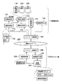
図1は本実施の形態の映像監視システムの概略構成図である。図1に示すように、撮像装置側1には、映像撮像部100(高画素の広角の固定カメラ)と領域制御部110と画像記憶部120と画像合成部130と映像選択部140と画像符号化部150とネットワーク接続部160等を備えて、高画質の広角映像と部分映像とを同時に得るようにしている。
<
FIG. 1 is a schematic configuration diagram of a video monitoring system according to the present embodiment. As shown in FIG. 1, the
また、監視センター側3には、ネットワーク接続部300と画像復号化部310と映像表示部320と映像制御部330等を備えている。
The monitoring center side 3 includes a
この監視センター側3と撮像装置側1とは通信ネットワーク200によって接続されている。
The monitoring center side 3 and the
(撮像装置側の構成)
映像撮像部100は、被写体を高精細に撮像し、映像デジタルデータとして出力する部分であり、比較的広範囲の映像を撮像するために用いるレンズ(広角レンズ、魚眼レンズなど)、高画素の撮像素子(35万画素以上)、そしてA/D変換器等で構成されている。
(Configuration on the imaging device side)
The
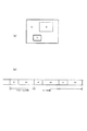
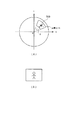
領域制御部110は、映像撮像部で読み出す映像範囲を制御するものである。この映像範囲は、例えば、図2(a)に示すように、映像撮像部100のカメラ画像の領域(全体領域はA、注目する部分領域B、C)に対応したピクセル座標(図2(b)参照)が予めメモリ110aに保存される。図2(a)の全体領域Aを3分割(A1、A2、A3)にしてメモリに記憶したのが図2(b)である。つまり、1フレームの読み出し時間は1/30秒と決められており、部分領域B、Cは分割領域A1、A2、A3より領域が小さいので、結果として部分領域B、Cの映像は分割領域の映像より、読み出しが早く終わり、分割領域の映像は、部分映像の映像より、時間がかかって読み出されることになる。つまり、部分領域B、Cは小さい領域であるので、読み出しにかかる時間は映像フレーム周期より短くなるので、残りの時間で全体画像を読み出している。
The
前述の全体領域A、部分領域B,Cは、予め設定される場合(初期設定領域という)又は監視センター側3によって指定させられる。 The above-described entire area A and partial areas B and C are designated in advance (referred to as an initial setting area) or designated by the monitoring center side 3.
画像記憶部120は、映像撮像部100からの映像データ(A1、A2、A3、B、C)を取り込む毎に、その画像データ一枚を単位としてメモリに記憶する部分であり、全体領域Aの分割領域である。A1領域の映像、A2領域の映像、A3領域の映像が保存されるバッファ、B領域の映像が保存されるバッファ、C領域の映像が保存されるバッファを有する。そして、画像合成部130には全体領域A(A1、A2、A3)の映像と、部分領域Bの映像又は部分領域Cの映像のいずれかの映像とを出力し、映像選択部140には、全体領域A(A1、A2、A3)の映像又は部分領域Bの映像若しくは部分領域Cのいずれかを出力する。また、この画像記憶部120の構成について、詳細に後術する。
Each time image data (A1, A2, A3, B, C) is captured from the
画像合成部130は、画像記憶部120に保存されている全体領域の映像A(A1、A2、A3)に部分領域Bの映像又は部分領域Cの映像を合成出力する。例えば、全体領域Aの分割領域(A1、A2、A3)映像に、1/30秒で読み出した部分領域B又はCの映像を合成して出力(合成画像ともいう)する。
The
映像選択部140は、画像記憶部120又は画像合成部130の映像データの中から所定の画像を、監視センター側3からの指示に従って選択する部分であり、画像記憶部120の全体領域A(A1、A2、A3)の映像、部分領域Bの映像又はC領域の映像を選択若しくは画像合成部130の合成画像を選択する。
The
画像符号化部150は、予め決められた符号化パラメータまたは監視センター側3の映像制御部330によって指定された符号化パラメータで画像の符号化を行なう部分であり、符号化方法にはMPEGやJPEGなどの各種規格があるが、符号量制御のし易さや監視者側の端末の多様性を考えると、国際標準であるJPEG2000やMotion JPEG2000が最適である。
The
ネットワーク接続部160は、符号化されたデータを所定の通信プロトコル(インターネット)で通信ネットワーク200を介して画像データを監視センター側3に送信する。
The
(監視センター側の構成)
映像制御部330は、映像表示部320に領域選択のためのサブ画面(図示せず)を表示させたり、部分領域の変更のためのサブ画面を表示させる。そして、これらのサブ画面の設定項目を通信ネットワーク200を介して撮像装置側1の領域制御部110、映像選択部140、画像合成部130に送信させる。
(Configuration on the monitoring center side)
The video control unit 330 causes the
また、画像復号化部310は、ネットワーク接続部300によって得られた映像信号を復号化して映像表示部320に表示する。
In addition, the
(画像記憶部の構成)
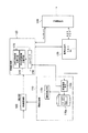
図3は画像記憶部120の概略構成図である。図3に示すように、画像記憶部120は、全体領域Aを分割して得た分割映像A1、A2、A3を1フレーム周期で記憶・読み出しするための多数の全体分割映像記憶手段170(170a、170b、170c、…)と、B領域映像記憶手段220と、C領域映像記憶手段210と、書き込み及び読み出しのタイミングを制御するコントローラ230等を備えて、1/30秒で全体領域の映像と部分領域の映像とを同時に記憶することを可能とする。
(Configuration of image storage unit)
FIG. 3 is a schematic configuration diagram of the
全体分割映像記憶手段170aは、バッファ240aと、バッファ240bとを備え、映像撮像部100からA1領域のピクセルデータを第1のスイッチング手段250aが入力し、第1のスイッチング手段250aが例えばバッファ240aを書き込み用として切り換えて、A1領域のピクセルデータをこの書き込み用バッファ240aに書き込みせると同時に、第2のスイッチング手段250bがバッファ240bを読み出し用として切り換え、このバッファ250のA1領域のピクセルデータを読み出して出力する。つまり、A1のピクセルデータをバッファ240aに保存させると同時にバッファ240bからA1のピクセルデータを読み出して、次にはバッファ240bを書き込み用とすると共に、バッファ240aを読み出し用とするような動作を第1のスイッチング手段250a、第2のスイッチング手段250bが行うことで、例えばA1の映像データを2/90秒で読み出している。
The entire divided
また、全体分割映像記憶手段170bは、バッファ260aと、バッファ260bとを備え、映像撮像部100からA2領域のピクセルデータを第3のスイッチング手段270aが入力し、第3のスイッチング手段270aが例えばバッファ260aを書き込み用として切り換えて、A2領域のピクセルデータをこの書き込み用バッファ260aに書き込みせると同時に、第4のスイッチング手段270bがバッファ260bを読み出し用として切り換え、このバッファ260bのA2領域のピクセルデータを読み出して出力する。つまり、A2のピクセルデータをバッファ260aに保存させると同時にバッファ260bからA2のピクセルデータを読み出して、次にはバッファ260bを書き込み用とすると共に、バッファ260aを読み出し用とするような動作を第3のスイッチング手段270a、第4のスイッチング手段270bが行うことで、例えばA2の映像データ(ピクセルデータの集まり)を2/90秒で読み出している。
The whole divided
さらに、全体分割映像記憶手段170cは、バッファ280aと、バッファ280bとを備え、映像撮像部100からA3領域のピクセルデータを第5のスイッチング手段290aが入力し、第5のスイッチング手段290aが例えばバッファ280aを書き込み用として切り換えて、A3領域のピクセルデータをこの書き込み用バッファ280aに書き込みせると同時に、第6のスイッチング手段290bがバッファ290bを読み出し用として切り換え、このバッファ290bのA3領域のピクセルデータを読み出して出力する。つまり、A3のピクセルデータをバッファ280aに保存させると同時にバッファ280bからA3のピクセルデータを読み出して、次にはバッファ280bを書き込み用とすると共に、バッファ280aを読み出し用とするような動作を第5のスイッチング手段290a、第6のスイッチング手段290bが行うことで、例えばA3の映像データ(ピクセルデータの集まり)を2/90秒で読み出している。
Further, the entire divided
C部分領域映像記憶手段210a(B領域映像記憶手段については省略する)は、バッファ291aと、バッファ291bとを備え、映像撮像部100からC領域のピクセルデータをC領域用の第1のスイッチング手段292aが入力し、C領域用の第1のスイッチング手段292aが例えばバッファ291aを書き込み用として切り換えて、C領域のピクセルデータをこの書き込み用バッファ291aに書き込みせると同時に、C領域用の第2のスイッチング手段292bがバッファ291bを読み出し用として切り換え、このバッファ291bのC領域のピクセルデータを読み出して出力する。つまり、Cのピクセルデータをバッファ291aに保存させると同時にバッファ291bからCのピクセルデータを読み出して、次にはバッファ291bを書き込み用とすると共に、バッファ291aを読み出し用とするような動作をC領域用の第1のスイッチング手段292a、C領域用の第2のスイッチング手段292bが行うことで、例えばCの映像データを1/90秒で読み出している。すなわち、部分領域の映像は、早く読み込まれ、分割映像(A1、A2、A3)は、部分領域の映像より時間をかけて読み込まれることになる。
The C partial area video storage unit 210a (not shown for the B area video storage unit) includes a
コントローラ230は、領域制御部110から領域読込情報(A1、A2、A3、B、C)を入力し、現在どの領域を読み込んでいるかを判断し、A1領域の場合は全体分割映像記憶手段170a、A2領域の場合は全体分割映像記憶手段170b、A3領域の場合は全体分割映像記憶手段170cを起動させている。また、領域Cの場合は、C部分領域映像記憶手段210を起動させている。
The
(動作説明)
上記のように構成された映像監視システムについて動作を説明する。
(Description of operation)
The operation of the video surveillance system configured as described above will be described.
通常、映像撮像部100の撮像素子に高画素タイプのものを用いると、全ての画素データを読み出すのにかかる時間はTVなどの映像フレーム周期(1/30秒)を越え、最終的に得られる映像は自然な動きにならず、コマ落ちした映像になる。
Usually, when a high-pixel type image sensor is used as the
しかし、監視用途では撮像される映像範囲全体が滑らかな映像である必要は少なく、特に従来のタイムラプスVTRを用いた監視では、時間的に飛び飛びの画像を間欠記録している。 However, in the monitoring application, it is not necessary that the entire image range to be captured is a smooth image, and in particular, in the monitoring using the conventional time lapse VTR, intermittent images are temporally recorded.
このタイムラプスVTRでは、しばしば重要な決定的瞬間を取り損なうといった欠点があり、注目点だけでも滑らかな映像で記録したいといった要求がある。 This time-lapse VTR has a drawback that it often misses an important decisive moment, and there is a demand for recording a smooth image even at a point of interest alone.
そこで、高画素タイプの撮像素子を用い、注目点領域の映像のみを読み出すことで高精細な映像を映像フレーム周期内に読み出すことが可能になる。 Therefore, it is possible to read out a high-definition video within a video frame period by using a high-pixel type image sensor and reading out only the video of the region of interest.
しかし、注目点領域だけではなく、更に広範囲の映像も同時に監視したいという要求もある。もし、固定カメラによる監視の場合、注目点以外の部分はほとんど動きが無いため、更新は映像フレーム周期である必要が無い場合もある。このような場合において、本実施の形態は有効である。 However, there is a demand for monitoring not only the attention area but also a wider range of images at the same time. In the case of monitoring by a fixed camera, there is a case where the update does not need to be a video frame period because there is almost no movement except for the attention point. In such a case, the present embodiment is effective.
つまり、図4(a)に示すように、全体領域Aに対して、部分領域Cが領域制御部110に設定されている場合は、図4(b)に示すように、1フレーム周期の初めの時間で映像領域Cの部分を領域制御部110が映像撮像部100から読み出させることにする。
That is, as shown in FIG. 4A, when the partial area C is set in the
この映像領域Cは全体領域Aと比較してかなり小さい領域であるため、読み出しにかかる時間は映像フレーム周期より短くなる。そこで、図4(b)に示すように余った時間で全体映像領域Aを分割した領域A1、A2、A3の読み出しのために用いる。全体映像領域Aは、1フレーム周期内では読み出しきれないため、図4(b)に示すようにA1(例えば1/3)、A2(例えば1/3)、A3(例えば1/3)と何回かに分けて読み出し、数フレームかかって全てが読み出されることになる。 Since this video area C is a considerably smaller area than the entire area A, the time required for reading is shorter than the video frame period. Therefore, as shown in FIG. 4B, it is used for reading out the areas A1, A2, and A3 obtained by dividing the entire video area A by the extra time. Since the entire video area A cannot be read within one frame period, as shown in FIG. 4B, what is A1 (for example, 1/3), A2 (for example, 1/3), A3 (for example, 1/3) Reading is performed in several times, and everything is read out in several frames.
すなわち、1フレーム目では全体分割映像記憶手段170aによってA1領域の映像データが読み込まれ(例えば2/90秒)、2フレーム目では全体分割映像記憶手段170bによってA2領域の映像データが読み込まれ(例えば2/90秒)、3フレーム目では全体分割映像記憶手段170cによってA3の領域の映像データが読み込まれる(例えば2/90秒)。 That is, in the first frame, the video data of the A1 area is read by the whole divided video storage means 170a (for example, 2/90 seconds), and in the second frame, the video data of the A2 area is read by the whole divided video storage means 170b (for example, 2/90 seconds) In the third frame, the video data in the area A3 is read by the whole divided video storage means 170c (for example, 2/90 seconds).
一方、C領域はC部分領域映像記憶手段210によって読み込まれる。この映像領域Cは全体領域Aと比較してかなり小さい領域であるため、読み出しにかかる時間は例えば1/90秒となり、1フレームで全体領域、部分領域を読み込むする時間は、1/30秒を満足することになる。
On the other hand, the C area is read by the C partial area
このようにすると、部分映像Cは欠落無く読み出せ、全体映像Aはコマ落ちするものの何フレームかに1回新しい画像に更新することができる。 In this way, the partial video C can be read without omission, and the entire video A can be updated to a new image once every several frames although frames are dropped.
上記のように部分映像Cと全体映像A(A1、A2、A3)を読み出して、一度、画像記憶部110で記憶し、画像合成部130で合成して画像符号化部150によってJPEG2000で符号化する場合を考えると、前記部分領域Cは注目点であるので画質を落とさず符号化し、全体領域Aはそれほど重要ではない部分なので必要に応じて画質を落として符号化することができる。また、監視者の機器がPC、PDA、携帯電話といった様々な表示解像度を持った端末であったり、通信ネットワークの帯域が様々である場合があるため、画像符号化部150でMotion JPEG2000の符号化を行なう時に解像度や画質が制御できるプログレッシブ機能を用いることにする。
As described above, the partial video C and the whole video A (A1, A2, A3) are read out, stored once in the
図5は本実施の形態の動作を説明するシーケンス図である。初めに撮像装置側1は、監視センター側に映像撮像部100で取得した全体の映像(A)を送信する(d1)。この、全体の映像には、領域設定部110で予め設定されている初期設定領域が分かるようにして送信させている。例えばA領域の画像の領域Bは、ドア、C領域は棚とした初期設定領域である。
FIG. 5 is a sequence diagram for explaining the operation of the present embodiment. First, the
そして、監視センターのオペレータは、映像表示部320に表示された部分領域枠付きの全体映像を確認し、この部分領域で監視を行う場合は、「OK」コマンドを入力して送信させる(d2)。
Then, the operator of the monitoring center confirms the entire video with the partial area frame displayed on the
撮像装置側の領域制御部110は、初期設定領域で「OK」とされたときは、初期設定領域を内部に設定(ピクセル座標)する共に、このA領域、B領域、C領域の読み出しであることを領域を画像記憶部120に知らせる読み出し領域決定処理を行う(d3)。
When “OK” is set in the initial setting area, the
また、監視センターのオペレータは、例えば領域A(A1、A2、A3)と領域Cとの合成画像の選択であることを知らせるコマンドを送信させる(d4)。 In addition, the operator of the monitoring center transmits a command notifying that it is the selection of the composite image of the area A (A1, A2, A3) and the area C (d4).
これらの設定後で、領域AC映像の同時読み出し処理を行う(d13)。領域AC映像の同時読み出し処理は、領域制御部110が初期設定領域の映像を映像撮像部100から送出させ、画像記憶部120は、1フレーム目では全体分割映像記憶手段170aによってA1領域の映像データを読み込み(例えば2/90秒)、2フレーム目では全体分割映像記憶手段170bによってA2領域の映像データを読み(例えば2/90秒)、3フレーム目では全体分割映像記憶手段170cによってA3の領域の映像データを読みこむ(例えば2/90秒)。
After these settings, the simultaneous reading process of the area AC video is performed (d13). In the simultaneous reading process of the area AC video, the
また、1フレーム目、2フレーム目、3フレーム目の全体映像が出力される毎に、C領域の映像データがC部分領域映像記憶手段210によって読み込まれ(1/90秒)、メモリ12bのC領域の映像が更新される。 Also, every time the first frame, the second frame, and the third frame are output, the C area image data is read by the C partial area image storage means 210 (1/90 seconds), and the C data in the memory 12b is read. The video in the area is updated.
つまり、高画素のカメラを用いていても、1/30秒毎に注目する領域であるC領域の映像は、常に最新の映像データにされ、かつ全体映像が得られる。 That is, even when a high-pixel camera is used, the video in the area C, which is the area of interest every 1/30 seconds, is always the latest video data, and the entire video is obtained.
一方、画像合成部130は、全体画像A(A1、A2、A3)と領域Cとの合成と設定されている場合は、画像記憶部120のメモリ120aの領域Aの全体画像から領域Cの映像を除いた全体映像(C領域が空白)を取りだすと共にメモリ120aに切り換えて、この全体映像の空白領域にメモリ120bの領域Cの映像を重ねる領域Cの画像を合成させる処理を行う(d5)。
On the other hand, when the
次に、映像選択部140は、映像合成部130を選択し、この映像合成部130で選択された合成画像(A、C)を画像符号化部150で符号化させてネットワーク接続部160によって、監視センター側に送信させる(d6)。つまり、監視センターの映像表示部320には、早く(本実施の形態では1/90秒)切り替わる部分映像が得られると共に3フレーム(6/90秒)での全体領域の映像が表示される。
Next, the
また、監視センター側のオペレータが映像領域Bのみを選択した場合は、映像領域Bの選択を映像制御部330はネットワーク接続部300を介して撮像装置に送信する(d7)。 When the operator on the monitoring center side selects only the video area B, the video control unit 330 transmits the selection of the video area B to the imaging apparatus via the network connection unit 300 (d7).
撮像装置の映像選択部140は、画像記憶部120から映像領域B(1フレームでは1/90秒)を選択する。読み出す処理を行い(d8)、画像符号化部150で符号化させて監視センターに送信する(d9)。
The
すなわち、監視センターの映像表示部320には、映像領域B(ドア)の映像だけが映ることになる。
That is, only the video of the video area B (door) is displayed on the
また、部分領域である映像領域B、Cを変更することも可能である。この変更を行うには、例えば画面のB領域枠、C領域枠をマウス等で移動させる。 It is also possible to change the video areas B and C which are partial areas. In order to make this change, for example, the B area frame and the C area frame of the screen are moved with a mouse or the like.
この移動させられた部分領域が映像制御部330によって読み込まれて、ネットワーク接続部300によって領域制御部110に送信される(d10)。
The moved partial area is read by the video controller 330 and transmitted to the
領域制御部110は、新たな部分領域を各部に設定し(d11)、これを初期設定領域として監視センターに送信する(d12)。
The
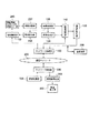
次に、領域制御部110と画像記憶部120の構成の概念を図6を用いて説明する。図6に示すように、領域制御部110は、初期設定領域を保存するメモリ110aと、領域設定手段110bと、領域読出手段110c等から構成されている。
Next, the concept of the configuration of the
すなわち、領域設定手段110bは、監視センターから送信された画像読み出しのための領域(A1、A2、A3、B、C:撮像素子の座標)をメモリ110aに保存し、領域読出手段110cが映像撮像部100で被撮像物を撮影する毎に、そのフレーム毎にA1領域、A2領域、A3領域の順に読み出しさせる。
That is, the
画像記憶部120は、全体分割映像記憶手段170、部分領域映像記憶手段220,230、コントローラ230等から構成されている。
The
すなわち、広範囲の映像を高画素で撮像できる映像撮像部100と、この撮像領域の全体領域または撮像領域内の一部分領域の画素情報を読み出す領域制御部110と、映像撮像部100から読み出した全体領域と部分領域の映像データを逐次一時格納する複数の画像記憶部120と、画像記憶部の画像データを合成する画像合成部130と、画像記憶部120の映像データや画像合成部120の映像データのうち一つを選択する映像選択部140と、映像選択部140からの画像データをデータ圧縮する画像符号化部150と、データ圧縮された映像データを通信ネットワークに対して送受信するネットワーク接続部160等を撮像装置側1に備え、また、監視センター側3には、圧縮映像データの復元を行なう画像符号化部310と、復元された映像データを表示する映像表示部310、映像制御部330を持ち、監視者のいる遠隔地からの指示により、全体映像(A1、A2、A3を合成),全体映像中の一部分映像(B、C),そしてこの2つの映像を合成した合成映像の3種類の映像から任意の映像を選択して監視する映像監視システムである。
That is, a
<実施の形態2>
本実施の形態は、実施の形態1に加えて過去の全体映像と現在の全体映像の差分から動き範囲を検出して撮像素子からの映像データ読み出し領域を指定する機能を有する動き検出部を設け、監視者が領域を指定せずとも動き領域の映像を監視できるようにした映像監視システムである。
<
In addition to the first embodiment, the present embodiment is provided with a motion detection unit having a function of detecting a motion range from a difference between a past whole video and a current whole video and designating a video data reading area from an image sensor. This is a video monitoring system in which the video of the motion area can be monitored without the monitor specifying the area.
また、映像記憶装置を設け、監視者がリアルタイムの映像ばかりでなく、過去に格納された映像記憶装置内の映像も表示できるようにした映像監視システムである。 Further, the video monitoring system is provided with a video storage device so that the monitor can display not only real-time video but also video in the video storage device stored in the past.
さらに、映像撮像部295に魚眼レンズ、双曲面ミラー、放物面ミラー、円錐ミラーなどの全方位視角センサを用い、極めて広範囲な撮像領域の全体やその一部分領域を表示できるようにした映像監視システムである。
Furthermore, an image monitoring system using an omnidirectional viewing angle sensor such as a fisheye lens, a hyperboloidal mirror, a parabolic mirror, and a conical mirror in the
さらに、全方位映像内の一部分の領域の画像データから歪を取り除いた画像データへ変換(平面にするための座標変換)する画像変換部297を設け、監視者に対して歪みの無い映像表示を実現する映像監視システムである。
Furthermore, an
図7は、図1の基本的な構成に加えて、魚眼レンズ又は放物面ミラー等を備えた映像撮像部295、画像変換部297、動き検出部298、記録装置299等を設けている。
FIG. 7 includes a
但し、動き検出部298、記録装置299、画像変換部297は全てが同時に存在する必要は無く、個々の機能が個別あるいは組合せで存在していても良い。
However, the
動き検出部298は、映像監視用途に重要な動体検出の機能を実現する部分である。この動き検出部298によって動き領域を特定することにより、自動的に領域制御部110の領域A、B、Cを更新して自動監視できるようにしている。
The
また、記録装置299は、符号化した映像データを記録しておき、監視者がいつでも見ることができるようにしている。
The
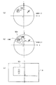
画像変換部297は、例えば、図8の(A)のように魚眼レンズや双曲面ミラーなどの全方位センサによって撮像された画像から図8の(B)のような歪の無い平面から見た画像を得るためには、画像歪を取り除きたい領域500の中心座標(X,Y)および画角(θ)が必要である。この領域500は、領域制御部110に予め設定されている。
The
このような画像変換処理により、監視者は直接人間の目で見たような自然な映像(図8の(B))として監視映像を見ることができる。 By such an image conversion process, the monitor can view the monitor video as a natural video (B in FIG. 8) as seen directly by human eyes.
すなわち、動き検出部298が画像記憶部120に保存された全体領域の画像を図8に示す座標系に定義し、この座標系において動きを検出したとき、その検出した領域の座標を定め、この座標枠を新たな部分領域として領域制御部110に設定する。
That is, when the
例えば、図9(a)に示すように、人物が移動したことを動き検出部298で検出し、新たに人物が移動した領域を図9(b)に示すように定め、この領域を新たな部分領域501として領域制御部110に設定(部分領域の更新)する(実際は図9(c)に示すように歪み補正された映像で領域設定がされている)。
For example, as shown in FIG. 9 (a), the
従って、侵入者を検出したときは、その人物を追尾した映像を監視センター側に送信できると共に、その部分領域の映像は1フレーム当たり1/90秒であるから、人物の行動を正確に知らせることになる。 Therefore, when an intruder is detected, an image tracking the person can be transmitted to the monitoring center side, and the image of the partial area is 1/90 second per frame, so that the action of the person can be accurately notified. become.
1 撮像装置側
100 映像撮像部
110 領域制御部
120 画像記憶部
130 画像合成部
140 映像選択部
150 画像符号化部
320 映像表示部
330 映像制御部
DESCRIPTION OF
Claims (2)
前記撮像装置は、
予め設定されている撮像域の全体領域を分割した分割領域、該全体領域内の部分領域からなる読み出し領域を設定し、前記映像撮像部からのフレームの映像が入力する毎に、前記読み出し領域に従って前記分割領域の画像データ、前記部分領域の画像データを順次出力する領域制御部と、
前記部分領域の画像データ、前記分割領域の画像データを記憶して、
前記部分領域の画像データを前記フレームの読み出し時間より短い時間で読み込み、かつ前記読み出し時間の残りの時間で前記分割領域の画像データを読み込む画像記憶部と、
前記監視センターの指示に基づいて前記画像記憶部の全体領域の映像データ、部分領域の映像データとを合成する画像合成部と、
前記画像合成部の合成画像又は前記画像記憶部の分割領域、部分領域のいずれかの映像データを選択して、送信させる映像選択部と、
を有することを特徴とする映像監視システム。 A video imaging unit that can capture a wide range of video with high pixels, and an image encoding unit that compresses the image data are provided in the imaging device, transmitted to a monitoring center via a communication network, and controlled by the monitoring side A video surveillance system for controlling an image readout area of an imaging unit,
The imaging device
A division area obtained by dividing the entire area of the imaging area set in advance and a readout area consisting of partial areas within the entire area are set, and each time a video of a frame from the video imaging unit is input, the readout area is An area controller for sequentially outputting the image data of the divided areas and the image data of the partial areas;
Store the image data of the partial area, the image data of the divided area,
An image storage unit that reads the image data of the partial area in a time shorter than the readout time of the frame, and reads the image data of the divided area in the remaining time of the readout time;
An image synthesis unit that synthesizes video data of the entire area of the image storage unit and video data of the partial area based on an instruction from the monitoring center;
A video selection unit that selects and transmits video data of either a composite image of the image synthesis unit or a divided region or a partial region of the image storage unit;
A video surveillance system comprising:
前記カメラから映像データを平面に歪み補正する画像変換部と、
前記画像変換部からの映像データを入力し、該映像データに動きを検出したとき、その領域を求め、該領域を前記部分領域として前記領域制御部に新たに設定する動き検出部と
を有することを特徴とする請求項1記載の映像監視システム。
The video imaging unit has a camera capable of photographing the surroundings at once,
An image conversion unit for correcting distortion of the video data from the camera into a plane;
When the video data from the image conversion unit is input and motion is detected in the video data, the region is obtained, and the motion detection unit newly sets the region as the partial region in the region control unit The video surveillance system according to claim 1.
Priority Applications (1)
| Application Number | Priority Date | Filing Date | Title |
|---|---|---|---|
| JP2003338392A JP2005109725A (en) | 2003-09-29 | 2003-09-29 | Video image monitoring system |
Applications Claiming Priority (1)
| Application Number | Priority Date | Filing Date | Title |
|---|---|---|---|
| JP2003338392A JP2005109725A (en) | 2003-09-29 | 2003-09-29 | Video image monitoring system |
Publications (1)
| Publication Number | Publication Date |
|---|---|
| JP2005109725A true JP2005109725A (en) | 2005-04-21 |
Family
ID=34533922
Family Applications (1)
| Application Number | Title | Priority Date | Filing Date |
|---|---|---|---|
| JP2003338392A Pending JP2005109725A (en) | 2003-09-29 | 2003-09-29 | Video image monitoring system |
Country Status (1)
| Country | Link |
|---|---|
| JP (1) | JP2005109725A (en) |
Cited By (3)
| Publication number | Priority date | Publication date | Assignee | Title |
|---|---|---|---|---|
| JP2007081553A (en) * | 2005-09-12 | 2007-03-29 | Hitachi Kokusai Electric Inc | Display method of camera system and camera system |
| JP2007272558A (en) * | 2006-03-31 | 2007-10-18 | Nippon Telegr & Teleph Corp <Ntt> | Disaster prevention monitoring system and its disaster prevention equipment and monitoring center |
| JP2009246917A (en) * | 2008-04-01 | 2009-10-22 | Hitachi Ltd | Video display device, and video processing apparatus |
-
2003
- 2003-09-29 JP JP2003338392A patent/JP2005109725A/en active Pending
Cited By (3)
| Publication number | Priority date | Publication date | Assignee | Title |
|---|---|---|---|---|
| JP2007081553A (en) * | 2005-09-12 | 2007-03-29 | Hitachi Kokusai Electric Inc | Display method of camera system and camera system |
| JP2007272558A (en) * | 2006-03-31 | 2007-10-18 | Nippon Telegr & Teleph Corp <Ntt> | Disaster prevention monitoring system and its disaster prevention equipment and monitoring center |
| JP2009246917A (en) * | 2008-04-01 | 2009-10-22 | Hitachi Ltd | Video display device, and video processing apparatus |
Similar Documents
| Publication | Publication Date | Title |
|---|---|---|
| JP3870124B2 (en) | Image processing apparatus and method, computer program, and computer-readable storage medium | |
| US7450165B2 (en) | Multiple-view processing in wide-angle video camera | |
| JP4345829B2 (en) | Image display system, image display apparatus, image display method, and program | |
| JP5109697B2 (en) | Image transmission device, image reception device, image transmission / reception system, image transmission program, and image reception program | |
| JP7282798B2 (en) | Imaging device, image processing method, and program | |
| JP4804378B2 (en) | Video display device and video display method | |
| JP2006033793A (en) | Tracking video reproducing apparatus | |
| JP2010521844A (en) | Monitoring system | |
| EP1460837B1 (en) | Digital still camera | |
| CN108347557A (en) | Panoramic image capturing device, display device, capturing method, and display method | |
| US11539909B2 (en) | Controlling a pan-tilt-zoom camera | |
| KR20100018998A (en) | Omnidirectional monitoring camera system and an image processing method using the same | |
| JP2005175970A (en) | Imaging system | |
| KR101280443B1 (en) | apparatus of processing regional image and method thereof | |
| JP2005109725A (en) | Video image monitoring system | |
| JP2009100259A (en) | Surveillance camera and image surveillance system | |
| JP4596987B2 (en) | Imaging device | |
| JP2008515273A (en) | Method for encoding partial video images | |
| JP2006121320A (en) | Omnidirectional monitor camera device | |
| KR20170011928A (en) | Camera system for compensating distortion of lens using super wide angle camera and Transport Video Interface Apparatus used in it | |
| JP2006165664A (en) | Image transmission / reception system | |
| JP2017085333A (en) | Photographing system | |
| JP5102481B2 (en) | Image processing system | |
| JP2006270346A (en) | Video distribution system and network camera | |
| JP2003324728A (en) | Imaging apparatus |