JP2005084659A - Assembly tool of lens housing for bending optical system - Google Patents
Assembly tool of lens housing for bending optical system Download PDFInfo
- Publication number
- JP2005084659A JP2005084659A JP2003320294A JP2003320294A JP2005084659A JP 2005084659 A JP2005084659 A JP 2005084659A JP 2003320294 A JP2003320294 A JP 2003320294A JP 2003320294 A JP2003320294 A JP 2003320294A JP 2005084659 A JP2005084659 A JP 2005084659A
- Authority
- JP
- Japan
- Prior art keywords
- lens
- jig
- variable
- optical system
- optical
- Prior art date
- Legal status (The legal status is an assumption and is not a legal conclusion. Google has not performed a legal analysis and makes no representation as to the accuracy of the status listed.)
- Withdrawn
Links
- 230000003287 optical effect Effects 0.000 title claims abstract description 248
- 238000005452 bending Methods 0.000 title claims abstract description 43
- 238000003384 imaging method Methods 0.000 claims abstract description 53
- 239000000758 substrate Substances 0.000 description 62
- 239000010410 layer Substances 0.000 description 53
- 239000000463 material Substances 0.000 description 46
- 239000004983 Polymer Dispersed Liquid Crystal Substances 0.000 description 42
- 239000010409 thin film Substances 0.000 description 42
- 239000004973 liquid crystal related substance Substances 0.000 description 35
- 238000010586 diagram Methods 0.000 description 31
- 230000008859 change Effects 0.000 description 28
- 239000010408 film Substances 0.000 description 23
- 238000007689 inspection Methods 0.000 description 21
- 239000012530 fluid Substances 0.000 description 17
- 238000000034 method Methods 0.000 description 16
- 229920000642 polymer Polymers 0.000 description 16
- 230000000694 effects Effects 0.000 description 15
- 238000013461 design Methods 0.000 description 12
- 238000012360 testing method Methods 0.000 description 12
- 239000012780 transparent material Substances 0.000 description 12
- 239000004988 Nematic liquid crystal Substances 0.000 description 11
- 230000008901 benefit Effects 0.000 description 11
- 238000002834 transmittance Methods 0.000 description 11
- 238000004519 manufacturing process Methods 0.000 description 9
- 230000004075 alteration Effects 0.000 description 8
- DMLAVOWQYNRWNQ-UHFFFAOYSA-N azobenzene Chemical compound C1=CC=CC=C1N=NC1=CC=CC=C1 DMLAVOWQYNRWNQ-UHFFFAOYSA-N 0.000 description 8
- 230000002093 peripheral effect Effects 0.000 description 8
- 238000012545 processing Methods 0.000 description 8
- 229920000800 acrylic rubber Polymers 0.000 description 7
- 230000010354 integration Effects 0.000 description 7
- 229920000058 polyacrylate Polymers 0.000 description 7
- 239000000126 substance Substances 0.000 description 7
- 229920003002 synthetic resin Polymers 0.000 description 6
- 239000000057 synthetic resin Substances 0.000 description 6
- 239000011368 organic material Substances 0.000 description 5
- 229920002379 silicone rubber Polymers 0.000 description 5
- XEEYBQQBJWHFJM-UHFFFAOYSA-N Iron Chemical group [Fe] XEEYBQQBJWHFJM-UHFFFAOYSA-N 0.000 description 4
- 230000009471 action Effects 0.000 description 4
- 229910052782 aluminium Inorganic materials 0.000 description 4
- XAGFODPZIPBFFR-UHFFFAOYSA-N aluminium Chemical compound [Al] XAGFODPZIPBFFR-UHFFFAOYSA-N 0.000 description 4
- 229920001577 copolymer Polymers 0.000 description 4
- 239000013078 crystal Substances 0.000 description 4
- 230000005684 electric field Effects 0.000 description 4
- 239000007788 liquid Substances 0.000 description 4
- 230000005291 magnetic effect Effects 0.000 description 4
- 230000005540 biological transmission Effects 0.000 description 3
- 229920001971 elastomer Polymers 0.000 description 3
- 239000003302 ferromagnetic material Substances 0.000 description 3
- 239000011521 glass Substances 0.000 description 3
- 229910052751 metal Inorganic materials 0.000 description 3
- 239000002184 metal Substances 0.000 description 3
- BQCIDUSAKPWEOX-UHFFFAOYSA-N 1,1-Difluoroethene Chemical compound FC(F)=C BQCIDUSAKPWEOX-UHFFFAOYSA-N 0.000 description 2
- 239000002033 PVDF binder Substances 0.000 description 2
- 239000004642 Polyimide Substances 0.000 description 2
- XUIMIQQOPSSXEZ-UHFFFAOYSA-N Silicon Chemical compound [Si] XUIMIQQOPSSXEZ-UHFFFAOYSA-N 0.000 description 2
- 239000000853 adhesive Substances 0.000 description 2
- 230000001070 adhesive effect Effects 0.000 description 2
- LFVGISIMTYGQHF-UHFFFAOYSA-N ammonium dihydrogen phosphate Chemical compound [NH4+].OP(O)([O-])=O LFVGISIMTYGQHF-UHFFFAOYSA-N 0.000 description 2
- 229910000387 ammonium dihydrogen phosphate Inorganic materials 0.000 description 2
- 238000000149 argon plasma sintering Methods 0.000 description 2
- JRPBQTZRNDNNOP-UHFFFAOYSA-N barium titanate Chemical compound [Ba+2].[Ba+2].[O-][Ti]([O-])([O-])[O-] JRPBQTZRNDNNOP-UHFFFAOYSA-N 0.000 description 2
- 229910002113 barium titanate Inorganic materials 0.000 description 2
- 239000002775 capsule Substances 0.000 description 2
- 230000000295 complement effect Effects 0.000 description 2
- 239000000806 elastomer Substances 0.000 description 2
- 238000005516 engineering process Methods 0.000 description 2
- 230000010365 information processing Effects 0.000 description 2
- 235000015110 jellies Nutrition 0.000 description 2
- 239000008274 jelly Substances 0.000 description 2
- 238000001459 lithography Methods 0.000 description 2
- 239000012528 membrane Substances 0.000 description 2
- 238000012986 modification Methods 0.000 description 2
- 230000004048 modification Effects 0.000 description 2
- 235000019837 monoammonium phosphate Nutrition 0.000 description 2
- 235000019796 monopotassium phosphate Nutrition 0.000 description 2
- 239000003921 oil Substances 0.000 description 2
- 229920001721 polyimide Polymers 0.000 description 2
- 229920002635 polyurethane Polymers 0.000 description 2
- 239000004814 polyurethane Substances 0.000 description 2
- 229920002981 polyvinylidene fluoride Polymers 0.000 description 2
- 239000000523 sample Substances 0.000 description 2
- 229910052710 silicon Inorganic materials 0.000 description 2
- 239000010703 silicon Substances 0.000 description 2
- 239000002356 single layer Substances 0.000 description 2
- 125000006850 spacer group Chemical group 0.000 description 2
- XLYOFNOQVPJJNP-UHFFFAOYSA-N water Substances O XLYOFNOQVPJJNP-UHFFFAOYSA-N 0.000 description 2
- 238000004804 winding Methods 0.000 description 2
- MIZLGWKEZAPEFJ-UHFFFAOYSA-N 1,1,2-trifluoroethene Chemical group FC=C(F)F MIZLGWKEZAPEFJ-UHFFFAOYSA-N 0.000 description 1
- 229910052581 Si3N4 Inorganic materials 0.000 description 1
- 239000003570 air Substances 0.000 description 1
- 238000013459 approach Methods 0.000 description 1
- 238000003705 background correction Methods 0.000 description 1
- 239000000919 ceramic Substances 0.000 description 1
- 238000006243 chemical reaction Methods 0.000 description 1
- 239000011248 coating agent Substances 0.000 description 1
- 238000000576 coating method Methods 0.000 description 1
- 238000004891 communication Methods 0.000 description 1
- 239000000470 constituent Substances 0.000 description 1
- 238000012937 correction Methods 0.000 description 1
- 230000006866 deterioration Effects 0.000 description 1
- 239000004815 dispersion polymer Substances 0.000 description 1
- 230000005611 electricity Effects 0.000 description 1
- PVCRZXZVBSCCHH-UHFFFAOYSA-N ethyl n-[4-[benzyl(2-phenylethyl)amino]-2-(4-phenoxyphenyl)-1h-imidazo[4,5-c]pyridin-6-yl]carbamate Chemical compound N=1C(NC(=O)OCC)=CC=2NC(C=3C=CC(OC=4C=CC=CC=4)=CC=3)=NC=2C=1N(CC=1C=CC=CC=1)CCC1=CC=CC=C1 PVCRZXZVBSCCHH-UHFFFAOYSA-N 0.000 description 1
- XUCNUKMRBVNAPB-UHFFFAOYSA-N fluoroethene Chemical group FC=C XUCNUKMRBVNAPB-UHFFFAOYSA-N 0.000 description 1
- 238000005286 illumination Methods 0.000 description 1
- 238000010348 incorporation Methods 0.000 description 1
- 229910052742 iron Inorganic materials 0.000 description 1
- GQYHUHYESMUTHG-UHFFFAOYSA-N lithium niobate Chemical compound [Li+].[O-][Nb](=O)=O GQYHUHYESMUTHG-UHFFFAOYSA-N 0.000 description 1
- 238000005259 measurement Methods 0.000 description 1
- 238000000691 measurement method Methods 0.000 description 1
- 238000012544 monitoring process Methods 0.000 description 1
- 229910000402 monopotassium phosphate Inorganic materials 0.000 description 1
- 238000000465 moulding Methods 0.000 description 1
- PJNZPQUBCPKICU-UHFFFAOYSA-N phosphoric acid;potassium Chemical compound [K].OP(O)(O)=O PJNZPQUBCPKICU-UHFFFAOYSA-N 0.000 description 1
- 230000010287 polarization Effects 0.000 description 1
- 239000002861 polymer material Substances 0.000 description 1
- 238000003825 pressing Methods 0.000 description 1
- 230000002265 prevention Effects 0.000 description 1
- 230000011514 reflex Effects 0.000 description 1
- 230000004043 responsiveness Effects 0.000 description 1
- 239000005060 rubber Substances 0.000 description 1
- 150000003839 salts Chemical class 0.000 description 1
- 239000004065 semiconductor Substances 0.000 description 1
- HQVNEWCFYHHQES-UHFFFAOYSA-N silicon nitride Chemical compound N12[Si]34N5[Si]62N3[Si]51N64 HQVNEWCFYHHQES-UHFFFAOYSA-N 0.000 description 1
- 239000004945 silicone rubber Substances 0.000 description 1
- GGCZERPQGJTIQP-UHFFFAOYSA-N sodium;9,10-dioxoanthracene-2-sulfonic acid Chemical compound [Na+].C1=CC=C2C(=O)C3=CC(S(=O)(=O)O)=CC=C3C(=O)C2=C1 GGCZERPQGJTIQP-UHFFFAOYSA-N 0.000 description 1
- 239000007787 solid Substances 0.000 description 1
- 239000006104 solid solution Substances 0.000 description 1
- 239000011032 tourmaline Substances 0.000 description 1
- 229940070527 tourmaline Drugs 0.000 description 1
- 229910052613 tourmaline Inorganic materials 0.000 description 1
- 229920002554 vinyl polymer Polymers 0.000 description 1
Images


Landscapes
- Lens Barrels (AREA)
Abstract
Description
本発明は、銀塩カメラ,ビデオカメラ,電子スチルカメラ等に用いられる屈曲光学系用レンズ筐体の組立て治具に関する。 The present invention relates to an assembling jig for a lens housing for a bending optical system used in a silver salt camera, a video camera, an electronic still camera, and the like.
従来、光学部材の全てが入射光軸に沿って一線上に配置されている真直光学系用筐体の組立て方法や、入射光軸をミラー等で折り曲げた屈曲光学系用筐体の組立て方法は、知られている(例えば、特許文献1乃至3参照)。
ところで、これら公知の組立て方法では、何れも、組立て治具を筐体に対し光軸方向に出し入れして、光学部材を順次組込んで行く方式である。このため、組立て工数がかかるばかりか、治具と治具とを連結する場合に精度が落ち、筐体をある程度大きくしなければならないという問題があった。
また、特に、屈曲光学系は、真直光学系に比して、光軸に対しての光学部材のシフト(以下、単にδという)及びティルト(以下、単にεという)の、光学性能に寄与する度合いが大きい。そのため、光軸に対して精度の高いδ,εを有する光学部材の配置を必要とするが、それらをレンズ枠等の部品の精度で保証することは難しい。
本発明は、従来技術の有するこのような問題点に鑑みてなされたものであり、その目的とするところは、組立て治具とガイドロッドとスリーブとレンズの精度さえ保証されていれば、上記δ及びεの精度の高い配置を保証し得る、屈曲光学系用レンズ筐体の組立て治具を提供することにある。
By the way, all of these known assembly methods are systems in which an assembly jig is taken in and out of the housing in the optical axis direction, and optical members are sequentially assembled. For this reason, there is a problem that not only the assembly man-hours are required, but also the accuracy is lowered when the jigs are connected to each other, and the casing has to be enlarged to some extent.
In particular, the bending optical system contributes to the optical performance of the shift of the optical member with respect to the optical axis (hereinafter simply referred to as δ) and the tilt (hereinafter simply referred to as ε) compared to the straight optical system. The degree is large. Therefore, it is necessary to arrange optical members having δ and ε with high accuracy with respect to the optical axis, but it is difficult to guarantee them with the accuracy of components such as a lens frame.
The present invention has been made in view of such problems of the prior art, and the object of the present invention is to provide the above-mentioned δ as long as the accuracy of the assembly jig, guide rod, sleeve, and lens is guaranteed. An object of the present invention is to provide a bending optical system lens housing assembly jig that can guarantee a highly accurate arrangement of ε and ε.
上記目的を達成するため、本発明による屈曲光学系用レンズ筐体の組立て治具は、光軸に平行なガイドロッドの保持部を有する第1と第2のレンズ用保持治具と、屈曲光学系用保持治具と、撮像素子用保持治具とを有し、前記各保持部を前記ガイドロッドに係合させることにより、レンズ枠にレンズを組込むことができるようになっている。
これにより、各治具,ガイドロッド,スリーブ及びレンズの出来栄えのみによって高精度の光学性能が保証され、レンズ保持枠やミラー保持枠の精度を必要としないため、筐体の成形型の製作費や成形コストを低減させることができる。また、屈曲光学系用保持治具の活用によって、形状可変ミラーのAF(オートフォーカス)のための変形量の負担を低減させることができる。
In order to achieve the above object, an assembling jig for a bending optical system lens housing according to the present invention includes first and second holding jigs for a lens having guide rod holding parts parallel to the optical axis, bending optics, and the like. A system holding jig and an image sensor holding jig are provided, and the lenses can be incorporated into the lens frame by engaging the holding portions with the guide rods.
This ensures high-precision optical performance only by the quality of each jig, guide rod, sleeve and lens, and does not require the accuracy of the lens holding frame and mirror holding frame. The molding cost can be reduced. Further, by utilizing the bending optical system holding jig, it is possible to reduce the burden of deformation amount for the AF (autofocus) of the deformable mirror.
本発明によれば、少なくとも1つのレンズ系のピント調整と、撮像素子の位置調整とが同時に行えるようになっている。
これにより、広角及び望遠時のピンと位置を合致させるためのズーミングピント移動調整、ピント位置を固体撮像素子の撮像面に合致させるためのFC調整及びシェーデング調整を、レンズ組立てと同時に行なうことができ、形状可変ミラーの負担を低減させることができる。ここで、シェーデング調整とは、製作、組立て誤差によって発生する中心と周辺の光量差を、撮像素子を光軸に対してティルトさせることによって撮像面全体で均一にすることである。
According to the present invention, the focus adjustment of at least one lens system and the position adjustment of the image sensor can be performed simultaneously.
This allows zooming focus movement adjustment to match the position with the pin at wide angle and telephoto, and FC adjustment and shading adjustment to match the focus position to the imaging surface of the solid-state image sensor at the same time as the lens assembly. The burden on the deformable mirror can be reduced. Here, the shading adjustment is to make the light amount difference between the center and the periphery caused by manufacturing and assembly errors uniform on the entire imaging surface by tilting the imaging device with respect to the optical axis.
また、本発明によれば、前記レンズ保持治具は、光軸に対して直角方向に挿入可能で、且つ、光軸方向へ移動可能である。
これにより、レンズ群やレンズ枚数が多くなっても、筐体を比較的小さく構成することが可能となる。
また、本発明によれば、屈曲光学系は、光学特性可変光学素子またはミラーを含んでいる。
また、本発明によれば、上記光学特性可変光学素子は、可変ミラーまたは可変焦点レンズである。
According to the present invention, the lens holding jig can be inserted in a direction perpendicular to the optical axis and can be moved in the optical axis direction.
As a result, the housing can be made relatively small even when the number of lens groups and the number of lenses increases.
According to the invention, the bending optical system includes a variable optical property optical element or a mirror.
According to the invention, the optical characteristic variable optical element is a variable mirror or a variable focus lens.
本発明によれば、組立て治具とガイドロッド,スリーブ,レンズの製作精度さえ保証されていれば、レンズ等の入射光軸に対する偏心及び傾きの精度の高い配置を保証し得る、屈曲光学系用レンズ筐体の組立て治具を提供することができる。また、本発明によれば、優れた光学性能を有する高品質の筐体製品を、比較的廉価に且つ容易に量産することが出来る。 According to the present invention, as long as the assembling jig, guide rod, sleeve, and lens manufacturing accuracy are guaranteed, it is possible to ensure a highly accurate arrangement of the eccentricity and inclination with respect to the incident optical axis of the lens or the like. An assembly jig for the lens housing can be provided. Further, according to the present invention, high-quality housing products having excellent optical performance can be easily mass-produced at a relatively low cost.
以下、本発明の実施の形態を説明するが、それに先立ち、本発明が関係する屈曲光学系の特徴について説明する。形状可変ミラーに対して軸上光線が斜入射する光学系では、形状可変ミラーの光偏向特性の変化によって生じる収査の変動を小さく抑える必要がある。このために、光学系を構成するレンズ等の光学素子あるいは撮像素子を、図1に矢印で示すように、軸上光線の進行方向に対して、直角にシフトさせたり、ティルトさせたりするが、製作誤差に敏感な光学系になることがある。つまり、製作誤差があると、結像性能が低下し易い光学系になることがあるか、或いは、上記収査の変動を小さく抑えるために、形状可変ミラーより像側の光学系の結像倍率の絶対値を上げる必要が生じる。 Hereinafter, embodiments of the present invention will be described. Prior to that, the characteristics of the bending optical system related to the present invention will be described. In an optical system in which an on-axis light beam is obliquely incident on the deformable mirror, it is necessary to suppress the variation in the collection caused by the change in the optical deflection characteristics of the deformable mirror. For this purpose, an optical element such as a lens constituting the optical system or an imaging element is shifted or tilted at right angles to the traveling direction of the axial ray as indicated by an arrow in FIG. The optical system may be sensitive to manufacturing errors. In other words, if there is a manufacturing error, the optical performance of the optical system is likely to deteriorate, or the imaging magnification of the optical system closer to the image side than the deformable mirror in order to suppress the fluctuation of the above-mentioned collection. It is necessary to increase the absolute value of.
可変焦点レンズを用いた光学系においても、可変焦点レンズより像側の光学系の結像倍率を上げる方が収査変動が少ない場合があり、製作誤差に敏感な光学系になることがある。 Even in an optical system using a variable focus lens, there is a case where the variation in the inspection is less when the imaging magnification of the optical system on the image side is higher than that of the variable focus lens, and the optical system may be sensitive to manufacturing errors.
図1は、形状可変ミラーDMを用いた3倍ズームの例であるが、G1〜G5の各レンズ群は、収差を補正するために、光軸に対してそれぞれ矢印の方向に偏心あるいは傾斜せしめられている。軸上光線とは、物体中心を出て絞り中心を通り、像中心に到達する光線のことを指す。通常、軸上主光線のことを光軸と呼ぶ。 FIG. 1 shows an example of 3 × zoom using the deformable mirror DM. The lens groups G1 to G5 are decentered or tilted in the directions of the arrows with respect to the optical axis in order to correct aberrations. It has been. An axial ray refers to a ray that leaves the center of the object, passes through the center of the stop, and reaches the center of the image. Usually, the axial principal ray is called the optical axis.
ズーム時には、第2レンズ群G2と第4レンズ群G4とが独立して動き、ピント合わせを形状可変ミラーDMで行う。第4レンズ群G4は3つのレンズL6,L7,L8からなり、同一の保持枠で一体化されている。図2は第4レンズ群G4の詳細を示した図で、保持枠600の中にレンズL6,L7,L8が入っており、光学設計上収差を良くするために、レンズL6とレンズL7及びL8の中心軸(二点鎖線図示)は、保持枠中心(光軸:一点鎖線)に対して、それぞれ距離S1,S2だけ偏心させてある。このため、保持枠600は回転非対称になっている。
なお、偏心量S1,S2はシフト偏心の値を示しているが、ティルト偏心していても以下の調整方法、検査方法は適用できる。
During zooming, the second lens group G2 and the fourth lens group G4 move independently, and focus adjustment is performed by the shape variable mirror DM. The fourth lens group G4 includes three lenses L6, L7, and L8, and is integrated with the same holding frame. FIG. 2 is a diagram showing details of the fourth lens group G4. Lenses L6, L7, and L8 are contained in the
Although the eccentric amounts S1 and S2 indicate the values of shift eccentricity, the following adjustment method and inspection method can be applied even if the tilt is eccentric.
保持枠600の中に、レンズL7及びL8とレンズL6を順次挿入して接着していけば、レンズ群G4の組立てはできるのであるが、レンズ外径と保持枠内径の製作誤差のために、偏心量S1,S2が設計値通りにならない場合がある。そこで、生産時に、簡易的にレンズL6とレンズL7及びL8を許容値内におさえる調整方法と調整器について、以下に述べる。
If the lenses L7 and L8 and the lens L6 are sequentially inserted into the
図3は、レンズ群G4のレンズL6とレンズL7及びL8を調整するための偏心調整器の概略図である。図中、光源601から出た光は、ピンホール602を通り、輝点を形成する。この光は、偏心調整器のレンズ603を通り、第4レンズ群G4に入る。そして、第4レンズ群G4に対応して作られた治具レンズ604を通り、更にレンズ605を通り、テレビカメラ606に点像を結像する。テレビカメラ606からのビデオ信号は、点像の形および位置を検出する画像処理機能を備えたコンピュータ607を介して、テレビモニター608で観測することができる。治具レンズ604は、1つまたは複数のレンズ604a,604b,604cからなっており、それらの中心軸(一点鎖線)は少なくとも一つが偏心している。
FIG. 3 is a schematic diagram of an eccentricity adjuster for adjusting the lens L6 and the lenses L7 and L8 of the lens group G4. In the drawing, light emitted from the
上記偏心調整器において、第4レンズ群G4が設計通り作られているときは、輝点の形が最も小さく、ボケることなく、しかもテレビモニター608上の所定位置に輝点が来るように、レンズ604a,604b,604cは設計され、配置されている。従って、テレビモニター608上の点像の形状を観測しながら、調整棒600aまたは600bで、レンズL6またはレンズL7及びL8を突いて、テレビモニター608上の点像が最も小さくなるように、或いは、所定の位置に来るように調整してから、接着剤でレンズL6,レンズL7及びL8を保持枠600に固定すれば、設計値の偏心量S1,S2に近い値をもつ第4レンズ群G4が作られる。
In the decentration adjuster, when the fourth lens group G4 is made as designed, the shape of the bright spot is the smallest, so that the bright spot comes to a predetermined position on the
調整用治具レンズ604のレンズ系は、第4レンズ群G4の設計が変わる毎に、それに対応して設計するのが最良の方法であるが、一つの調整用治具レンズ604を、その位置あるいは調整用治具レンズ604全体の偏心状態を変えることで、異なる設計の第4レンズ群G4のために用いるようにしてもよい。調整用治具レンズ604の設計は、光学シミュレーションソフト等で調整用治具レンズ604に合わせて行うことができる。あるいは、調整用治具レンズ604のレンズ系を回転対称なレンズ系とし、つまり共軸系とし、調整用治具レンズ604のレンズ系全体をシフト偏心、ティルト偏心させて用いても良い。
It is best to design the lens system of the
なお、この偏心調整器の調整方法は、形状可変ミラーを用いた光学装置に限らず、設計上レンズ系が偏心している光学系を含む光学装置の調整に広く用いることができる。調整用治具レンズ604の構成レンズ604a,604b,604cとして球面レンズを用いれば、調整用治具レンズ604の製作が早くできてよい。
The method of adjusting the decentering adjuster is not limited to an optical device using a deformable mirror, but can be widely used for adjusting an optical device including an optical system in which the lens system is decentered by design. If spherical lenses are used as the
また、上記説明では、ピンホールで作られた輝点を調整用のテスト物体としたが、これに限らずテストチャート等を用いてもよい。また、上記説明では、テレビモニター上の点像を目視で観測して調整する例を示したが、パソコン607で点像を画像処理して良し悪しを判断し、調整するようにしてもよい。或いは、テレビカメラ606,パソコン607及びテレビモニター608を用いずに、点像の形または位置をルーペまたは顕微鏡で拡大して観察し、第4レンズ群G4の評価を行なってもよい。また、調整に限らず、第4レンズ群G4の検査をするのに偏心調整器を用いてもよい。
In the above description, the bright spot formed by the pinhole is the test object for adjustment. However, the present invention is not limited to this, and a test chart or the like may be used. In the above description, the point image on the television monitor is visually observed and adjusted. However, the point image may be image-processed by the
図4は、別の偏心調整器(または検査器)の例で、フィゾー型の干渉計609を用いて、調整用治具レンズ604及び被検レンズである第4レンズ群G4等を通過した光の波面の形を観測し、第4レンズ群G4等を調整あるいは検査する装置である。干渉計609を出た光は、調整用治具レンズ604及び被検レンズである第4レンズ群G4等を通過し、ミラー610で反射され、逆の光路を辿って干渉計609に入る。波面の形をパソコン607で解析し、被検レンズを評価することができる。この偏心調整器は、図3に示した偏心調整器に比べて、高精度な調整ができる点で、優れている。
FIG. 4 shows another example of an eccentricity adjustment device (or inspection device). Light that has passed through an
なお、偏心量S1,S2は、以下の条件を満たすと良い。
0.0001≦|S1/f|≦1000
0.0001≦|S2/f|≦1000
ここで、fは第4レンズ群G4の焦点距離である。
上限を上回るとレンズ系の設計性能が低下し、下限を下回ると偏心の効果がなくなる。
第4レンズ群G4のレンズのティルト偏心をTとすれば、同様の理由で、
0.001°≦|T|≦ 20°
を満たすと良い。
The eccentric amounts S1 and S2 should satisfy the following conditions.
0.0001 ≦ | S1 / f | ≦ 1000
0.0001 ≦ | S2 / f | ≦ 1000
Here, f is the focal length of the fourth lens group G4.
If the upper limit is exceeded, the design performance of the lens system will be degraded, and if the lower limit is not reached, the decentration effect will be lost.
If the tilt eccentricity of the lens of the fourth lens group G4 is T, for the same reason,
0.001 ° ≦ | T | ≦ 20 °
It is good to meet.
この場合、例えば、被検レンズである第4レンズ群G4等が設計値通りにできあがった場合、干渉計609で観測される波面が略ヌルフリンジになるように、調整用治具レンズ604は設計・製作されている。そうすると、テレビモニター608上の干渉縞を目視でみながら、ヌルフリンジに近付くよう調整棒(600a),600bを動かして調整すればよいので、調整が容易である。
In this case, for example, when the fourth lens group G4, which is the lens to be tested, is completed according to the design value, the
なお、図4で調整用治具レンズ604を無しにして、被検レンズである第4レンズ群G4等を通過した光の波面の干渉縞を観測し、それが設計上定まる波面形状にどれだけ近いかを、パソコン607で波面を解析し、調整棒600a,600bで調整し、または検査を行なっても良い。
In FIG. 4, the
図4では、フィゾー型干渉計を用いた例を示したが、それに替えて、マッハツェンダー型,トワイマングリーン型等の干渉計を用いてもよく、それらの場合、干渉計のアームの一方に第4レンズ群G4等の設計値に極く近い基準レンズを置き、もう一方のアームに被検レンズである第4レンズ群G4等を置けばよい。 FIG. 4 shows an example in which a Fizeau interferometer is used. Alternatively, a Mach-Zehnder type or Twiman Green type interferometer may be used, and in such a case, one of the arms of the interferometer is used. A reference lens extremely close to the design value of the fourth lens group G4 and the like may be placed, and the fourth lens group G4 and the like as the test lens may be placed on the other arm.
図5は、トワイマングリーン型の干渉計を用いた場合の例を示している。図中、611はレーザ光源、612はハーフミラー、613は設計通りに作られた基準レンズ、614はミラー、615はCCDテレビカメラである。この場合も、図4に関連して説明したのと同様にして、被検レンズである第4レンズ群G4等の調整または検査が行なわれる。 FIG. 5 shows an example in which a Twiman Green interferometer is used. In the figure, 611 is a laser light source, 612 is a half mirror, 613 is a reference lens made as designed, 614 is a mirror, and 615 is a CCD TV camera. In this case as well, adjustment or inspection of the fourth lens group G4, which is the lens to be tested, is performed in the same manner as described with reference to FIG.
以上の説明では、形状可変ミラーDMを有する光学装置の中の一部の偏心した光学系の調整について述べたが、これに限らず、可変焦点レンズを有する光学装置あるいは光学特性可変素子を有しない光学装置においても、偏心光学系を含む場合には、その光学系の調整,検査,測定に上記の各種方法は用いることができる。 In the above description, adjustment of a part of the decentered optical system in the optical device having the deformable mirror DM has been described. However, the present invention is not limited to this, and the optical device having the variable focus lens or the optical characteristic variable element is not provided. Even in an optical apparatus, when an eccentric optical system is included, the above-described various methods can be used for adjustment, inspection, and measurement of the optical system.
以下、本発明の実施例を説明する。
図6は図1のレンズ構成に対応した本発明にかかる屈曲光学系用レンズ筐体の一部を破断して示す概略平面図、図7は本発明による組立て治具が非組付け位置にある場合の全体配置を示す平面図、図8は図7に示す組立て治具が各光学部材を組付けた状態にある場合の平面図である。
Examples of the present invention will be described below.
6 is a schematic plan view showing a part of a lens case for a bending optical system according to the present invention corresponding to the lens configuration of FIG. 1, and FIG. 7 is an assembly jig according to the present invention in a non-assembled position. FIG. 8 is a plan view when the assembly jig shown in FIG. 7 is in a state where each optical member is assembled.
図7及び8において、Aは後述する各治具ブロックを保持する一対の基板を結合してなる組立て台、1は組立て台Aに取付けられた治具ブロック1a上に矢印方向(光軸方向)へ摺動可能に取付けられていてレンズ枠1bを有する1群治具、2は組立て台Aに取付けられていて位置決め治具2aを有する治具ブロック2b上に矢印方向(光軸方向及び光軸と直交する方向)へ摺動可能に取付けられレンズ枠2cを有する2群治具、3は組立て台A上に矢印方向(光軸方向)へ摺動・固定可能に取付けられていてレンズ枠3aを有する3群治具、4は組立て台Aに取付けられていて位置決め治具4aを有する治具ブロック4b上に矢印方向(光軸方向及び光軸と直交する方向)へ摺動可能に取付けられレンズ枠4cを有する4群治具、5は3群冶具3上に矢印方向(光軸方向)へ摺動・固定可能に取付けられていてレンズ枠5aを有する5群治具、6は組立て台A上に取付けられていてミラー枠6aを有するたミラー治具、7は組立て台Aに取付けられた治具ブロック7a上に矢印方向(光軸方向)へ摺動可能に取付けられていてID枠7bを有するID治具である。上記各冶具は高精度で製作されており、そのレンズ枠は形状とレンズ胴付け面の寸法が高精度で製作されており、また、各摺動部は極めて円滑に摺動が行われ得るように製作されている。
7 and 8, A is an assembly table formed by combining a pair of substrates holding each jig block to be described later, and 1 is an arrow direction (optical axis direction) on the jig block 1a attached to the assembly table A. The
次に、上記組立て冶具を用いて、筐体Fへの各光学部材の組付けについて説明する。図7の状態において、先ず、その長手方向中心線と平行に延びた一対のガイドロッドGDを組み込んで予め準備された屈曲筐体Fを、ミラー枠装着用凹部F1が、形状可変ミラーDMを仮保持したミラー冶具6のミラー枠6aと整合するような姿勢で、上方より3群及び5群冶具3及び5の上方に位置させ、次に、第3群レンズ群G3を仮嵌めした3群冶具3のレンズ枠3aが、筐体Fの3群保持枠部F2に隣接する所定位置(図9参照)に、また、第5レンズ群G5を仮嵌めした5群冶具5のレンズ枠5aが、筐体Fの5群保持枠部F3に隣接する所定位置(図12参照)に、それぞれ来るように、3群冶具3及び5群冶具5の位置を調整して固定する。これにより、筐体Fは、組立て台Aの上方所定位置に正しく定置される。
Next, assembly of each optical member to the housing F will be described using the assembly jig. In the state of FIG. 7, first, a bending housing F prepared in advance by incorporating a pair of guide rods GD extending in parallel with the longitudinal center line thereof, a mirror frame mounting recess F1 temporarily mounts the variable shape mirror DM. The third group jig in which the third group lens group G3 is temporarily fitted after being positioned above the third group and fifth group jigs 3 and 5 in an attitude that aligns with the mirror frame 6a of the held
このとき、3群冶具3のレンズ枠3aに形成された一対の段部3a'はガイドロッドGRに当接し(図10参照)、この段部3a'と協働してガイドロッドGRを挟持する斜面3b'を有する固定板3bを、固定ビス3cにより、3群冶具3に固定することにより、ガイドロッドGRは光軸と平行になるように保持され、レンズ枠3aに保持された第3レンズ群G3は、3群保持枠部F2に隣接した光軸上の位置に正しく位置せしめられる(図10及び11参照)。この場合、図9に示された如く、第3群レンズG3の一部G3−2の胴付け面と3群保持枠部F2の内周面との間には、僅かな隙間が形成されるように設計されている。
At this time, a pair of
また、5群冶具5のレンズ枠5aに形成された一対の段部5a'はガイドロッドGRに当接し(図13参照)、この段部5a'と協働してガイドロッドGRを挟持する斜面5b'を有する固定板5bを、固定ビス5cにより、5群冶具5に固定することにより、ガイドロッドGRは光軸と平行になるように保持され、レンズ枠5aに保持された第5レンズ群G5は、光軸上に正しく位置せしめられる(図14参照)。
Further, a pair of
この場合、レンズ枠5aのレンズ保持胴部は、図13に示すように、円周に沿って3等分割されているため、これと相補的に円周に沿って3等分割されている5群保持枠部F3のレンズ保持胴部に進入して組み合わされる(図13参照)ため、レンズ枠5aに保持された第4レンズ群G4は、光軸上に正しく位置せしめられる。なお、この状態で、図12に示した如く、第5群レンズG5の一部G5−1の表面とこれに対応する5群保持枠部F3の受け面との間、及び第5群レンズG5のたの一部G5−2の表面とこれに対応する5群保持枠部F3の受け面との間には、それぞれ僅かな隙間が存在するように設計されている。
In this case, as shown in FIG. 13, the lens holding body portion of the
この状態で、レンズ枠1aに第1レンズ群G1を仮嵌めして、1群冶具1を図7において矢印方向へ摺動させ、第1群レンズG1を筐体Fの1群保持枠部F4へ挿入する(図15参照)。
In this state, the first lens group G1 is temporarily fitted to the lens frame 1a, the
次に、図7に示す位置で、2群冶具2のレンズ枠2cに第2群レンズG2を仮嵌めした後、2群冶具2を矢印y方向へ所定量摺動させ、次にこれを2群位置決め冶具2aに当接するまで矢印x方向へ摺動させる。このとき、2群冶具2のレンズ枠2cに形成された一対の段部2c'はガイドロッドGRに当接し(図16及び17参照)、この段部2c'と協働してガイドロッドGRを挟持する斜面2d'を有する固定板2dを、固定ビス2eにより2群冶具2に固定することにより、2群冶具2は、ガイドロッドGRを衝にして正しい位置に保持される。その結果、レンズ枠2cに保持された第2レンズ群G2は、光軸上に正しく位置せしめられ、予め筐体F内に組み込まれている図示しないカム環により光軸に沿って移動せしめられるズーミング用カムフォロア8の2群保持枠8aに隣接せしめられる(図18参照)。
Next, after temporarily fitting the second group lens G2 to the
この場合、図18に示した如く、第2群レンズG2の一部G2−2の胴付け面と2群保持枠8aの内周面との間、及び第2群レンズG2の一部G2−2の表面とこれに対応する第2群保持枠8aの受け面との間には、僅かな隙間が存在するように設計されている。
In this case, as shown in FIG. 18, a part G2-2 of the second group lens G2 and the inner peripheral surface of the second
次に、図7に示す位置で、4群冶具4のレンズ枠4cに第4群レンズG4を仮嵌めした後、4群冶具4を矢印x方向へ所定量摺動させ、次にこれを位置決め冶具4aに当接するまで矢印y方向へ摺動させる。このとき、4群冶具4のレンズ枠4cに形成された一対の斜面4c'はガイドロッドGRに当接し(図19及び20参照)、この斜面4c'と協働してガイドロッドGRを挟持する段部4d'を有する一対の固定片4dを、固定ビス4eによりレンズ枠4cに固定することにより、4群冶具4は、ガイドロッドGRを衝にして正しい組込み位置に持ち来たされる。
この場合、レンズ枠4cのレンズ保持胴部は、円周に沿って3等分割されているため、これと相補的に円周に沿って3等分割されている第4群レンズ保持枠9のレンズ保持胴部に進入して組み合わされる(図19参照)ため、レンズ枠4cに保持された第4レンズ群G4は、光軸上に正しく位置せしめられる。なお、この状態で、図21に示した如く、第4群レンズG4の胴付け面と第4群レンズ保持枠9のレンズ保持胴部の内周面との間、及び第4群レンズG4の表面とこれに対応する第4群レンズ保持枠9の受け面との間には、僅かな隙間が存在するように設計されている。
Next, after temporarily fitting the fourth group lens G4 to the
In this case, since the lens holding body of the
最後に、図7に示す位置で、ID冶具7のID枠7bの胴付部7b'に固体撮像素子IDを保持するID保持枠10を仮嵌めした後、ID冶具47を矢印方向へ所定量摺動させ、筐体Fの所定位置に位置せしめる(図22〜24参照)ことにより、各光学部材の筐体内への組込みを完了する(図8参照)。この場合、ID保持枠10の胴付部7b'による保持は、図23に示す如く、対向する二つのコーナ部でのみ行うように設計されている。
Finally, at the position shown in FIG. 7, after temporarily fitting the
この組込み状態で、前述の如き各光学部材の偏心及び傾き調整、ズーミングによる広角及び望遠撮影時でのピント位置のズレをなくすためのズーミングピント調整等を行うことを可能にするため、各冶具は、図25に例示すようにレンズを偏心させた状態で組付けたり、図26に例示するようにレンズ等を傾けて組付けたりすることが出来るように、必要に応じ6軸(x,y及びz方向の移動と回転)調整可能に構成されている。 In this built-in state, each jig is capable of performing eccentricity and inclination adjustment of each optical member as described above, zooming focus adjustment for eliminating a wide-angle zooming and focusing position shift during telephoto shooting, etc. As shown in FIG. 25, the six axes (x, y) can be assembled as necessary so that the lens can be assembled in an eccentric state, or the lens can be assembled with an inclination as shown in FIG. And movement and rotation in the z direction).
本実施例においては、第1レンズ群G1と固体撮像素子IDが光軸に対して所定量傾き、また、第5レンズ群G5が光軸に対して所定量偏心するように設計されているが、上記の組込み状態で、既述の測定方法等を用いてモニタしながら、最良の光学性能が得られるようにすると共に、固体撮像素子の出力を検出できる図示しないMTF検査機や、撮像面でのピント位置を検出できる図示しないコリメータ等を用いて、ズーミングピント調整やFC調整,シェーディング補正を行いながら、冶具を動かして各光学要素の位置を微調整し、最良の光学性能が得られるようにして、その位置で、各光学要素とその保持枠との間に設けた上記隙間に接着剤を注入して、光学要素をその保持枠に固着することにより、筐体への各光学要素の組み込みを完了する。また、このときの各冶具の最終調整位置は、適宜の方法で記憶される。 In this embodiment, the first lens group G1 and the solid-state imaging device ID are designed to be inclined by a predetermined amount with respect to the optical axis, and the fifth lens group G5 is designed to be eccentric by a predetermined amount with respect to the optical axis. In the above-described built-in state, the best optical performance can be obtained while monitoring using the above-described measurement method, etc., and the output of the solid-state image sensor can be detected. Using a collimator (not shown) that can detect the focus position of the lens, while performing zooming focus adjustment, FC adjustment, and shading correction, the jig is moved to finely adjust the position of each optical element so that the best optical performance can be obtained. Then, in that position, the adhesive is injected into the gap provided between each optical element and its holding frame, and the optical element is fixed to the holding frame, thereby assembling each optical element into the housing. The To completion. In addition, the final adjustment position of each jig at this time is stored by an appropriate method.
このようにして、筐体F内の所定位置に各光学要素を固定した後、上記の組込み手順と全く逆の順序と方法により、各冶具を図7の位置に戻した後、筐体Fを持上げれば、製品として取り出すことが出来る。この場合、各冶具のレンズ枠等には、レンズ等が仮嵌めされているだけであるから、この仮嵌め状態は容易に外され得る。 After fixing each optical element in a predetermined position in the housing F in this way, the jigs are returned to the positions shown in FIG. If it is lifted, it can be taken out as a product. In this case, since only a lens or the like is temporarily fitted to the lens frame or the like of each jig, this temporarily fitted state can be easily removed.
以上説明したような冶具の組込み及び取出し動作を繰返すことにより、筐体自身は高精度で製作されていなくても、治具とガイドロッド,スリーブ,光学要素さえ高精度で製作してあれば、優れた光学性能を有する高品質のレンズ筐体製品を、比較的廉価に且つ容易に量産することが出来る。 By repeating the assembling and unloading operations of the jig as described above, even if the housing itself is not manufactured with high accuracy, even if the jig, guide rod, sleeve, and optical element are manufactured with high accuracy, High-quality lens housing products having excellent optical performance can be easily mass-produced relatively inexpensively.
上記のような方法は、特に小型の光学系、例えば、PDA,携帯電話等の撮像系で有利である。また、これまで形状可変ミラーを用いた例について述べてきたが、可変焦点レンズ、通常のミラーを用いた光学系にも本発明は適用できる。 The above-described method is particularly advantageous in a small optical system, for example, an imaging system such as a PDA or a mobile phone. Moreover, although the example using a variable shape mirror has been described so far, the present invention can also be applied to an optical system using a variable focus lens and a normal mirror.
次に、本発明にかかるる光学系に適用可能な形状可変ミラー、可変焦点レンズ等、光学特性可変光学素子の構成例について説明する。
図27は上記本発明にかかる光学系に適用可能な光学特性可変光学素子として形状可変ミラーの一構成例を示す概略図である。
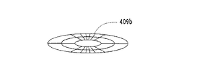
この構成例では、形状可変ミラー409は、変形する基板409jの上に形成されたアルミコーティング等で作られた薄膜(反射面)409aと、基板409jの下側に設けられた電極409kとの3層構造の周辺部が輪帯状の支持台423に支持されるとともに、電極409kとは間隔を設けて支持台423に取付けられた複数の電極409bと、各電極409bにそれぞれ接続されて駆動回路として機能する複数の可変抵抗器411aと、可変抵抗器411bと電源スイッチ413を介して電極409kと電極409b間に接続された電源412と、複数の可変抵抗器411aの抵抗値を制御するための演算装置414とで構成されており、演算装置414には、さらに温度センサー415、湿度センサー416及び距離センサー417が接続されて、これらは図示のように1つの光学装置の一部を構成している。なお、変形する基板409jは、薄膜でもよいし、板状でもよい。
Next, a configuration example of a variable optical property optical element such as a variable shape mirror and a variable focus lens applicable to the optical system according to the present invention will be described.
FIG. 27 is a schematic diagram showing a configuration example of a variable shape mirror as an optical characteristic variable optical element applicable to the optical system according to the present invention.
In this configuration example, the
形状可変ミラーの反射面は、演算装置414による制御により、平面でなくてもよく、球面、回転対称非球面の他、光軸に対して偏心した球面、平面、回転対称非球面、あるいは、対称面を有する非球面、対称面を1つだけ有する非球面、対称面のない非球面、自由曲面、微分不可能な点又は線を有する面等、いかなる形状にも制御される。以下、これらの面を総称して拡張曲面という。薄膜409aで形成される反射面により光線は矢印のように反射される。
The reflecting surface of the deformable mirror does not have to be a flat surface under the control of the
前記薄膜409aは、例えば、P.Rai-choudhury編、Handbook of Michrolithography, Michromachining and Michrofabrication, Volume 2:Michromachining and Michrofabrication,P495,Fig.8.58, SPIE PRESS刊やOptics Communication, 140巻(1997年)P187〜190に記載されているメンブレインミラーのように、複数の電極409bと電極409kの間に電圧が印加されると、静電気力により薄膜409aが変形してその面形状が変化するようになっている。
なお、電極409bの形は、例えば図29、図30に示すように、薄膜409aの変形のさせ方に応じて、同心分割、矩形分割にして、選べばよい。
The
The shape of the
上記のように、反射面としての薄膜409aの形状は、結像性能が最適になるように演算装置414からの信号により各可変抵抗器411aの抵抗値を変化させることにより制御される。すなわち、演算装置414へ、温度センサー415、湿度センサー416及び距離センサー417から周囲温度及び湿度並びに物体までの距離に応じた大きさの信号が入力され、演算装置414は、これらの入力信号に基づき周囲の温度及び湿度条件と物体までの距離、あるいは電子ズームのための画像処理装置303からの指令に基づき、薄膜409aの形状が決定されるような電圧を電極409bに印加するように、各変抵抗器411aの抵抗値を決定するための信号を出力する。このように、薄膜409aは電極409bに印加される電圧すなわち静電気力で変形させられ、その形状は状況により非球面を含む様々な拡張曲面の形状をとる。なお、距離センサー417はなくてもよく、その場合、例えば不図示の固体撮像素子408からの像の信号の高周波成分が略最大になるように物体距離を算出し、形状可変ミラーを変形させるようにすればよい。形状可変ミラー409はリソグラフィーを用いて作ると加工精度がよく、良い品質のものが得られやすく、良い。
As described above, the shape of the
また、変形する基板409jをポリイミドあるいは商品名サイトップ(旭硝子(株)製)等の合成樹脂で製作すれば、低電圧でも大きな変形が可能であるので好都合である。
図27の構成例では変形する基板409jをはさんで反射面としての薄膜409aと変形する電極409kを別に設けて一体化しているので、製造法がいくつか選べるメリットがある。また反射面としての薄膜409aを導電性の薄膜としてもよい。このようにすると、変形する電極409kを兼ねることができ、両者が1つになるので、構造が簡単になるメリットがある。
形状可変ミラーの反射面の形状は自由曲面にするのが良い。なぜなら収差補正が容易にでき、有利だからである。
In addition, it is convenient to make the deformable substrate 409j with a synthetic resin such as polyimide or trade name Cytop (manufactured by Asahi Glass Co., Ltd.) because large deformation is possible even at a low voltage.
In the configuration example of FIG. 27, since the
The shape of the reflecting surface of the deformable mirror should be a free-form surface. This is because aberration correction can be performed easily and advantageously.
また、図27の構成例では、演算装置414、温度センサー415、湿度センサー416、距離センサー417を設け、温湿度変化、物体距離の変化等も形状可変ミラー409で補償するようにしたが、そうではなくてもよい。つまり、温度センサー415、湿度センサー416、距離センサー417を省いても良い。
In the configuration example of FIG. 27, the
図28は形状可変ミラー409の他の構成例を示す概略図である。
本構成例の形状可変ミラーは、反射面としての薄膜409aと電極409bとの間に圧電素子409cが介装されていて、これらが支持台423上に設けられている。そして、圧電素子409cに加わる電圧を各電極409b毎に変えることにより、圧電素子409cに部分的に異なる伸縮を生じさせて、薄膜409aの形状を変えることができるようになっている。電極409bの形は、図29に示すように、同心分割であってもよいし、図30に示すように、矩形分割であってもよく、その他、適宜の形のものを選択することができる。図28中、424は演算装置414に接続された振れ(ブレ)センサーであって、例えばこの構成例の光学装置をデジタルカメラに用いる場合には、デジタルカメラの振れを検知し、振れによる像の乱れを補償するように薄膜409aを変形させるべく、演算装置414及び可変抵抗器を内蔵した駆動回路411を介して電極409bに印加される電圧を変化させる。このとき、温度センサー415、湿度センサー416及び距離センサー417からの信号も同時に考慮され、ピント合わせ、温湿度補償等が行われる。この場合、薄膜409aには圧電素子409cの変形に伴う応力が加わるので、薄膜409aの厚さはある程度厚めに作られて相応の強度を持たせるようにするのがよい。
なお、駆動回路411は、電極409bの数に対応して複数配置する構成に限らず、1つの駆動回路でもって複数の電極409bを制御する構成にしてもよい。
FIG. 28 is a schematic view showing another configuration example of the
In the variable shape mirror of this configuration example, a
Note that the driving
図31は形状可変ミラー409のさらに他の構成例を示す概略構成図である。
本構成例の形状可変ミラーは、薄膜409aと電極409bの間に介置される圧電素子が逆方向の圧電特性を持つ材料で作られた2枚の圧電素子409c及び409c’で構成されている。すなわち、圧電素子409cと409c’が強誘電性結晶で作られ、結晶軸の向きが互いに逆になるように配置される。この場合、圧電素子409cと409c’は電圧が印加されると逆方向に伸縮するので、薄膜409aを変形させる力が、図28に示した1層構造の場合よりも強くなり、結果的にミラー表面の形を大きく変えることができるという利点がある。
FIG. 31 is a schematic configuration diagram showing still another configuration example of the
The variable shape mirror of this configuration example includes two
圧電素子409c,409c’に用いる材料としては、例えばチタン酸バリウム、ロッシエル塩、水晶、電気石、リン酸二水素カリウム(KDP)、リン酸二水素アンモニウム(ADP)、ニオブ酸リチウム等の圧電物質、同物質の多結晶体、同物質の結晶、PbZrO3とPbTiO3の固溶体の圧電セラミックス、二フッ化ポリビニール(PVDF)等の有機圧電物質、上記以外の強誘電体等があり、特に有機圧電物質はヤング率が小さく、低電圧でも大きな変形が可能であるので、好ましい。なお、これらの圧電素子を利用する場合、厚さを不均一にすれば、上記構成例において薄膜409aの形状を適切に変形させることも可能である。
Examples of the material used for the
また、圧電素子409c,409c’の材料としては、ポリウレタン、シリコンゴム、アクリルエラストマー、PZT、PLZT、ポリフッ化ビニリデン(PVDF)等の高分子圧電体、シアン化ビニリデン共重合体、ビニリデンフルオライドとトリフルオロエチレンの共重合体等が用いられる。
圧電性を有する有機材料や、圧電性を有する合成樹脂、圧電性を有するエラストマー等を用いると形状可変ミラー面の大きな変形が実現できてよい。
The materials of the
When an organic material having piezoelectricity, a synthetic resin having piezoelectricity, an elastomer having piezoelectricity, or the like is used, a large deformation of the deformable mirror surface may be realized.
なお、図28、図32に示す圧電素子409cに、例えば、アクリルエラストマー、シリコンゴム等の電歪材料を用いる場合には、1層構造の圧電素子409cを別の基板409c−1と電歪材料409c−2とを貼り合わせた2層構造にしてもよい。
When an electrostrictive material such as acrylic elastomer or silicon rubber is used for the
図32は形状可変ミラー409のさらに他の構成例を示す概略図である。
本構成例の形状可変ミラーは、圧電素子409cが薄膜409aと電極409dとにより挟持され、薄膜409aと電極409dとの間に演算装置414により制御される駆動回路425aを介して電圧が印加されるようになっており、さらにこれとは別に、支持台423上に設けられた電極409bにも演算装置414により制御される駆動回路425bを介して電圧が印加されるように構成されている。したがって、本構成例では、薄膜409aは電極409dとの間に印加される電圧と電極409bに印加される電圧による静電気力とにより二重に変形され得、上記実施例に示した何れのものよりもより多くの変形パターンが可能であり、かつ、応答性も速いという利点がある。
FIG. 32 is a schematic diagram showing still another configuration example of the
In the variable shape mirror of this configuration example, a
そして、薄膜409a、電極409d間の電圧の符号を変えれば、形状可変ミラーを凸面にも凹面にも変形させることができる。その場合、大きな変形を圧電効果で行ない、微細な形状変化を静電気力で行なってもよい。また、凸面の変形には圧電効果を主に用い、凹面の変形には静電気力を主に用いてもよい。なお、電極409dは電極409bのように複数の電極から構成されてもよい。この様子を図26に示した。なお、本願では、圧電効果と電歪効果、電歪をすべてまとめて圧電効果と述べている。従って、電歪材料も圧電材料に含むものとする。
If the sign of the voltage between the
図33は形状可変ミラー409のさらに他の構成例を示す概略図である。
本構成例の形状可変ミラーは、電磁気力を利用して反射面の形状を変化させ得るようにしたもので、支持台423の内部底面上には永久磁石426が、頂面上には窒化シリコン又はポリイミド等からなる基板409eの周縁部が載置固定されており、基板409eの表面にはアルミニウム等の金属コートで作られた薄膜409aが付設されていて、形状可変ミラー409を構成している。基板409eの下面には複数のコイル427が配設されており、これらのコイル427はそれぞれ駆動回路428を介して演算装置414に接続されている。したがって、各センサー415,416,417,424およびその他からの信号によって演算装置414において求められる光学系の変化に対応した演算装置414からの出力信号により、各駆動回路428から各コイル427にそれぞれ適当な電流が供給されると、永久磁石426との間に働く電磁気力で各コイル427は反発又は吸引または吸着され、基板409e及び反射面として機能する薄膜409aを変形させる。
FIG. 33 is a schematic view showing still another configuration example of the
The variable shape mirror of this configuration example can change the shape of the reflecting surface using electromagnetic force. A
この場合、各コイル427はそれぞれ異なる量の電流を流すようにすることもできる。また、コイル427は1個でもよいし、永久磁石426を基板409eに付設しコイル427を支持台423の内部底面側に設けるようにしてもよい。また、コイル427はリソグラフィー等の手法で作るとよく、さらに、コイル427には強磁性体よりなる鉄心を入れるようにしてもよい。
In this case, each
この場合、薄膜コイル427の巻密度を、図34に示すように、場所によって変化させたコイル428’とすることにより、基板409e及び薄膜409aに所望の変形を与えるようにすることもできる。また、コイル427は1個でもよいし、また、これらのコイル427には強磁性体よりなる鉄心を挿入してもよい。
In this case, as shown in FIG. 34, the winding density of the
図35は形状可変ミラー409のさらに他の構成例を示す概略図である。
本構成例の形状可変ミラーでは、基板409eは鉄等の強磁性体で作られており、反射膜としての薄膜409aはアルミニウム等からなっている。この場合、薄膜409a側にコイルを設けなくても、磁力によって薄膜409aを変形させることができるから、構造が簡単で、製造コストを低減することができる。また、電源スイッチ413を、各コイル427の電流の流れる方向を切換え可能にする切換え兼用の電源開閉用スイッチで置換すれば、コイル427に流れる電流の方向を変えることができ、基板409e及び薄膜409aの形状を自由に変えることができる。図36は本構成例におけるコイル427の一配置例を示し、図37はコイル427の他の配置例を示しているが、これらの配置は、図33に示した構成例にも適用することができる。なお、図38はコイル427の配置を図37に示したように放射状とした場合に適する永久磁石426の一配置例を示している。図38に示すように、棒状の永久磁石426を放射状に配置すれば、図33に示した構成例に比べて、微妙な変形を基板409e及び薄膜409aに与えることができる。また、このように電磁気力を用いて基板409e及び薄膜409aを変形させる場合(図33及び図35の構成例)は、静電気力を用いた場合よりも低電圧で駆動できるという利点がある。
FIG. 35 is a schematic view showing still another configuration example of the
In the variable shape mirror of this configuration example, the
以上いくつかの形状可変ミラーの構成例を述べたが、薄膜409aで変形されるミラーの形を変形させるのに、図32の構成例に示すように、2種類以上の力を用いてもよい。つまり静電気力、電磁力、圧電効果、磁歪、流体の圧力、電場、磁場、温度変化、電磁波等のうちから2つ以上を同時に用いて反射面を形成する薄膜を変形させてもよい。つまり2つ以上の異なる駆動方法を用いて光学特性可変光学素子を作れば、大きな変形と微細な変形とを同時に実現でき、精度の良い鏡面が実現できる。
Although several configuration examples of the variable shape mirror have been described above, two or more kinds of forces may be used to deform the shape of the mirror deformed by the
図39は本発明かかる光学系に適用可能な形状可変ミラー409を用いた撮像系、例えば携帯電話のデジタルカメラ、カプセル内視鏡、電子内視鏡、パソコン用デジタルカメラ、PDA用デジタルカメラ等に用いられる撮像系の概略構成図である。
FIG. 39 shows an imaging system using a
本実施例の撮像系は、形状可変ミラー409と、レンズ902と、固体撮像素子408と、制御系103とで一つの撮像ユニット104を構成している。本実施例の撮像ユニット104では、レンズ102を通った物体からの光は形状可変ミラー409で集光され、固体撮像素子408の上に結像する。形状可変ミラー409は、光学特性可変光学素子の一種であり、可変焦点ミラーとも呼ばれている。
In the imaging system of the present embodiment, the
本実施例によれば、物体距離が変わっても形状可変ミラー409を変形させることでピント合わせをすることができ、レンズをモータ等で駆動する必要がなく、小型化、軽量化、低消費電力化の点で優れている。また、撮像ユニット104は本発明の撮像系としてすべての実施例で用いることができる。また、形状可変ミラー409を複数用いることでズーム、変倍の撮像系、光学系を作ることができる。
なお、図39では、制御系103にコイルを用いたトランスの昇圧回路を含む制御系の構成例を示している。特に積層型圧電トランスを用いると、小型化できてよい。昇圧回路は電気を用いる形状可変ミラー、可変焦点レンズに用いることができるが、特に静電気力、圧電効果を用いる場合の形状可変ミラー、可変焦点レンズに有用である。なお、形状可変ミラー409でピント合わせを行うためには、たとえば固体撮像素子408に物体像を結像させ形状可変ミラー409の焦点距離を変化させつつ物体像の高周波成分が最大になる状態を見つければよい。高周波成分を検出するには、たとえば固体撮像素子408にマイクロコンピュータ等を含む処理装置を接続し、その中で高周波成分を検出すればよい。
なお、レンズ902を後述の可変焦点レンズで置き換えても良い。
同様に上記の効果が得られる。この場合、形状可変ミラー409は通常のミラーでも良い。またレンズ902と可変焦点レンズを併用しても良い。
According to this embodiment, even if the object distance changes, it is possible to focus by deforming the
FIG. 39 shows a configuration example of a control system including a transformer booster circuit using coils in the
The
Similarly, the above effect can be obtained. In this case, the
図40は形状可変ミラーのさらに他の構成例を示し、マイクロポンプ180で流体161を出し入れし、支持台189aの上部に張った膜で形成されるミラー面を変形させる形状可変ミラー188の概略図である。本実施例によれば、ミラー面を大きく変形させることが可能になるというメリットがある。図中、168は支持台189a内の流体161の量を、マイクロポンプ180とともに制御する制御装置であり、この制御装置168とマイクロポンプ180は、膜189の変形を制御するので、実施の形態の駆動回路304に相当する構成となる。
マイクロポンプ180は、例えば、マイクロマシンの技術で作られた小型のポンプで、電力で動くように構成されている。
マイクロマシンの技術で作られたポンプの例としては、熱変形を利用したもの、圧電材料を用いたもの、静電気力を用いたものなどがある。
FIG. 40 shows still another configuration example of the deformable mirror, and a schematic diagram of the
The
Examples of pumps made with micromachine technology include those using thermal deformation, those using piezoelectric materials, and those using electrostatic forces.
図41は図40に示したマイクロポンプ180の構成例を示す概略図である。本構成例のマイクロポンプ180では、振動板181は静電気力、圧電効果等の電気力により振動する。図41では静電気力により振動する例を示しており、図41中、182,183は電極である。また、点線は変形した時の振動板181を示している。振動板181の振動に伴い、2つの弁184,185が開閉し、流体161を右から左へ送るようになっている。
41 is a schematic diagram showing a configuration example of the
図40で示した形状可変ミラー188では、反射面を構成する膜189が流体161の量に応じて凹凸に変形することで、形状可変ミラーとして機能する。流体としては、シリコンオイル、空気、水、ゼリー、等の有機物、無機物を用いることができる。
The
なお、静電気力、圧電効果を用いた形状可変ミラー、可変焦点レンズなどにおいては、駆動用に高電圧が必要になる場合がある。その場合には、例えば図39に示すように、昇圧用のトランス、あるいは圧電トランス等を用いて制御系を構成するとよい。
また、反射面を形成する薄膜409a又は膜189は、支持台423あるいは支持台189aなどの輪帯状部分の上部などの変形しない部分に設けておくと、形状可変ミラーの反射面の形状を干渉計等で測定する場合に、基準面として使うことができ便利である。
Note that a high voltage may be required for driving in a deformable mirror, a variable focus lens, or the like using electrostatic force or a piezoelectric effect. In that case, for example, as shown in FIG. 39, the control system may be configured using a step-up transformer or a piezoelectric transformer.
Further, if the
図42は各実施の形態で述べた本発明の光学装置に適用可能な光学系を構成するレンズ、あるいはレンズ群の一部を、可変焦点レンズに置き換えて構成することにより、前記レンズあるいはレンズ群を光軸方向にズーミングしなくて済む構成とする可変焦点レンズの原理的構成を示す図である。この可変焦点レンズ511は、第1,第2の面としてのレンズ面508a,508bを有する第1のレンズ512aと、第3,第4の面としてのレンズ面509a,509bを有する第2のレンズ512bと、これらレンズ間に透明電極513a,513bを介して設けた高分子分散液晶層514とで構成される第3のレンズ512cとを有し、入射光を第1,第3,第2のレンズ512a,512c,512bを経て収束させるものである。透明電極513a,513bは、スイッチ515を介して交流電源516に接続して、高分子分散液晶層514に交流電圧を選択的に印加するようにする。なお、高分子分散液晶層514は、それぞれ液晶分子517を含む球状、多面体等の任意の形状の多数の微小な高分子セル518を有して構成し、その体積は、高分子セル518を構成する高分子および液晶分子517がそれぞれ占める体積の和に一致させる。
FIG. 42 shows a configuration of the lens or the lens group by replacing a part of the lens or the lens group constituting the optical system applicable to the optical apparatus of the present invention described in each embodiment with a variable focus lens. FIG. 2 is a diagram illustrating a principle configuration of a variable focus lens that does not require zooming in the optical axis direction. The
ここで、高分子セル518の大きさは、例えば球状とする場合、その平均の直径Dを、使用する光の波長をλとするとき、例えば、
2nm≦D≦λ/5 …(1)
とする。すなわち、液晶分子517の大きさは、2nm程度以上であるので、平均の直径Dの下限値は、2nm以上とする。また、Dの上限値は、可変焦点レンズ511の光軸方向における高分子分散液晶層514の厚さtにも依存するが、λに比べて大きいと、高分子の屈折率と液晶分子517の屈折率との差により、高分子セル518の境界面で光が散乱して高分子分散液晶層514が不透明になってしまうため、後述するように、好ましくはλ/5以下とする。可変焦点レンズが用いられる光学製品によっては高精度を要求しない場合もあり、そのときDはλ以下でよい。なお、高分子分散液晶層514の透明度は、厚さtが厚いほど悪くなる。
Here, when the size of the
2nm ≦ D ≦ λ / 5 (1)
And That is, since the size of the
また、液晶分子517は、例えば、一軸性のネマティック液晶分子を用いる。この液晶分子517の屈折率楕円体は、図43に示すような形状となり、
nox=noy=no …(2)
である。ただし、noは常光線の屈折率を示し、noxおよびnoyは、常光線を含む面内での互いに直交する方向の屈折率を示す。
As the
n ox = n oy = n o ... (2)
It is. However, n o is the refractive index of an ordinary ray, n ox and n oy are refractive indices in directions perpendicular to each other in a plane including an ordinary ray.
ここで、図42に示すように、スイッチ515をオフ、すなわち高分子分散液晶層514に電界を印加しない状態では、液晶分子517が様々な方向を向いているので、入射光に対する高分子分散液晶層514の屈折率は高く、屈折力の強いレンズとなる。これに対し、図44に示すように、スイッチ515をオンとして高分子分散液晶層514に交流電圧を印加すると、液晶分子517は、屈折率楕円体の長軸方向が可変焦点レンズ511の光軸と平行となるように配向するので、屈折率が低くなり、屈折力の弱いレンズとなる。
Here, as shown in FIG. 42, when the
なお、高分子分散液晶層514に印加する電圧は、例えば、図45に示すように、可変抵抗器519を用いることにより段階的あるいは連続的に変化させることもできる。このようにすれば、印加電圧が高くなるにつれて、液晶分子517は、その楕円長軸が徐々に可変焦点レンズ511の光軸と平行となるように配向するので、屈折力を段階的あるいは連続的に変えることができる。
The voltage applied to the polymer dispersed
ここで、図42に示す状態、すなわち高分子分散液晶層514に電圧を印加しない状態での、液晶分子517の平均屈折率nLC’は、図43に示すように、屈折率楕円体の長軸方向の屈折率をnzとすると、およそ
(nox+noy+nZ)/3≡nLC’ …(3)
となる。また、上記(2)式が成り立つときの平均屈折率nLCは、nzを異常光線の屈折率neと表して、
(2no+ne)/3≡nLC …(4)
で与えられる。このとき、高分子分散液晶層514の屈折率nAは、高分子セル518を構成する高分子の屈折率をnPとし、高分子分散液晶層514の体積に占める液晶分子517の体積の割合をffとすると、マックスウェル・ガーネットの法則により、
nA=ff・nLC’+(1−ff)nP …(5)
で与えられる。
Here, the average refractive index n LC ′ of the
It becomes. Moreover, average refractive index n LC when equation (2) is satisfied, it represents a n z the refractive index n e of the extraordinary ray,
(2n o + n e) / 3≡n LC ... (4)
Given in. At this time, the refractive index n A of the polymer dispersed
n A = ff · n LC '+ (1-ff) n P (5)
Given in.
したがって、図45に示すように、レンズ512aおよび512bの内側の面、すなわち高分子分散液晶層514側の面の曲率半径を、それぞれR1およびR2とすると、高分子分散液晶層で構成される第3のレンズ512cの焦点距離f1は、
1/f1=(nA−1)(1/R1−1/R2) …(6)
で与えられる。なお、R1およびR2は、曲率中心が像点側にあるとき、正とする。また、レンズ512aおよび512bの外側の面による屈折は除いている。つまり、高分子分散液晶層514のみによるレンズ512cの焦点距離が、(6)式で与えられる。
Therefore, as shown in FIG. 45, when the curvature radii of the inner surfaces of the
1 / f 1 = (n A −1) (1 / R 1 −1 / R 2 ) (6)
Given in. R 1 and R 2 are positive when the center of curvature is on the image point side. Further, refraction by the outer surfaces of the
また、常光線の平均屈折率を、
(nox+noy)/2=no’ …(7)
とすれば、図44に示す状態、すなわち高分子分散液晶層514に電圧を印加した状態での、高分子分散液晶層514の屈折率nBは、
nB=ff・no’+(1−ff)nP …(8)
で与えられるので、この場合の高分子分散液晶層514のみによるレンズ512cの焦点距離f2は、
1/f2=(nB−1)(1/R1−1/R2) …(9)
で与えられる。なお、高分子分散液晶層514に、図44に示す状態における電圧よりも低い電圧を印加する場合の焦点距離は、(6)式で与えられる焦点距離f1と、(9)式で与えられる焦点距離f2との間の値となる。
In addition, the average refractive index of ordinary light,
(N ox + n oy) / 2 = n o '... (7)
Then, the refractive index n B of the polymer dispersed
n B = ff · n o '+ (1-ff) n P (8)
In this case, the focal length f 2 of the
1 / f 2 = (n B −1) (1 / R 1 −1 / R 2 ) (9)
Given in. Note that the focal length when a voltage lower than the voltage in the state shown in FIG. 44 is applied to the polymer dispersed
上記(6)および(9)式から、高分子分散液晶層514による焦点距離の変化率は、
|(f2−f1)/f2|=|(nB−nA)/(nA−1)| … (10)
で与えられる。したがって、この変化率を大きくするには、|nB−nA|を大きくすればよい。ここで、
nB−nA=ff(no’−nLC’) …(11)
であるから、|no’−nLC’|を大きくすれば、変化率を大きくすることができる。実用的には、nBが、1.3〜2程度であるから、
0.01≦|no’−nLC’|≦10 …(12)
とすれば、ff=0.5のとき、高分子分散液晶層514による焦点距離を、0.5%以上変えることができるので、効果的な可変焦点レンズを得ることができる。なお、|no’−nLC’|は、液晶物質の制限から、10を越えることはできない。
From the above equations (6) and (9), the change rate of the focal length by the polymer dispersed
| (F 2 −f 1 ) / f 2 | = | (n B −n A ) / (n A −1) |
Given in. Therefore, in order to increase this rate of change, it is sufficient to increase | n B −n A |. here,
n B -n A = ff (n o '-n LC') ... (11)
Therefore, if | n o '−n LC ' | is increased, the rate of change can be increased. In practice, n B is from is about 1.3 to 2,
0.01 ≦ | no′− n LC ′ | ≦ 10 (12)
Then, when ff = 0.5, the focal length of the polymer-dispersed
次に、上記(1)式の上限値の根拠について説明する。「Solar Energy Materials and Solar Cells」31巻,Wilson and Eck,1993, Eleevier Science Publishers B.v.発行の第197 〜214 頁、「Transmission variation using scattering/transparent switching films 」には、高分子分散液晶の大きさを変化させたときの透過率τの変化が示されている。そして、かかる文献の第206 頁、図6には、高分子分散液晶の半径をrとし、t=300μm、ff=0.5、nP =1.45、nLC=1.585、λ=500nmとするとき、透過率τは、理論値で、r=5nm(D=λ/50、D・t=λ・6μm(ただし、Dおよびλの単位はnm、以下も同じ))のときτ≒90%となり、r=25nm(D=λ/10)のときτ≒50%になることが示されている。
Next, the basis of the upper limit value of the above equation (1) will be described. `` Solar Energy Materials and Solar Cells '' Vol. 31, Wilson and Eck, 1993, Eleevier Science Publishers Bv, pp. 197-214, “Transmission variation using scattering / transparent switching films” The change in transmittance τ when changed is shown. Further, in
ここで、例えば、t=150μmの場合を推定してみると、透過率τがtの指数関数で変化すると仮定して、t=150μmの場合の透過率τを推定してみると、r=25nm(D=λ/10、D・t=λ・15μm)のときτ≒71%となる。また、t=75μmの場合は、同様に、r=25nm(D=λ/10、D・t=λ・7.5μm)のときτ≒80%となる。 Here, for example, assuming that t = 150 μm, assuming that the transmittance τ varies with an exponential function of t, and estimating the transmittance τ when t = 150 μm, r = When 25 nm (D = λ / 10, D · t = λ · 15 μm), τ≈71%. Similarly, when t = 75 μm, τ≈80% when r = 25 nm (D = λ / 10, D · t = λ · 7.5 μm).
これらの結果から、
D・t≦λ・15μm …(13)
であれば、τは70%〜80%以上となり、レンズとして十分実用になる。したがって、例えば、t=75μmの場合は、D≦λ/5で、十分な透過率が得られることになる。
From these results,
D ・ t ≦ λ ・ 15μm (13)
Then, τ is 70% to 80% or more, and it is sufficiently practical as a lens. Therefore, for example, when t = 75 μm, sufficient transmittance can be obtained with D ≦ λ / 5.
また、高分子分散液晶層514の透過率は、nPの値がnLC’の値に近いほど良くなる。一方、no’とnPとが異なる値になると、高分子分散液晶層514の透過率は悪くなる。図42に示した状態と図44に示した状態とで、平均して高分子分散液晶層514の透過率が良くなるのは、
nP=(no’+nLC’)/2 …(14)
を満足するときである。
Further, the transmittance of the polymer dispersed
n P = (n o '+ n LC ') / 2 (14)
When you are satisfied.
ここで、可変焦点レンズ511は、レンズとして使用するものであるから、図42の状態でも、図44の状態でも、透過率はほぼ同じで、かつ高い方が良い。そのためには、高分子セル518を構成する高分子の材料および液晶分子517の材料に制限があるが、実用的には、
no’≦nP≦nLC’ …(15)
とすればよい。
Here, since the
n o ′ ≦ n P ≦ n LC ′ (15)
And it is sufficient.
上記(14)式を満足すれば、上記(13)式は、さらに緩和され、
D・t≦λ・60μm …(16)
であれば良いことになる。なぜなら、フレネルの反射則によれば、反射率は屈折率差の2乗に比例するので、高分子セル518を構成する高分子と液晶分子517との境界での光の反射、すなわち高分子分散液晶層514の透過率の減少は、およそ上記の高分子と液晶分子517との屈折率の差の2乗に比例するからである。
If the above equation (14) is satisfied, the above equation (13) is further relaxed,
D ・ t ≦ λ ・ 60μm (16)
If it is good. This is because, according to Fresnel's reflection law, the reflectance is proportional to the square of the difference in refractive index, so that light is reflected at the boundary between the polymer constituting the
以上は、no’≒1.45、nLC’≒1.585の場合であったが、より一般的に定式化すると、
D・t≦λ・15μm・(1.585−1.45)2/(nu−nP)2 …(17)
であればよい。ただし、(nu−nP)2は、(nLC’−nP)2と(no’−nP)2とのうち、大きい方である。
The above is the case of n o ′ = 1.45 and n LC ′ = 1.585, but more generally formulated,
D · t ≦ λ · 15 μm · (1.585−1.45) 2 / (n u −n P ) 2 (17)
If it is. However, (n u −n P ) 2 is the larger of (n LC ′ −n P ) 2 and (n o ′ −n P ) 2 .
また、可変焦点レンズ511の焦点距離変化を大きくするには、ffの値が大きい方が良いが、ff=1では、高分子の体積がゼロとなり、高分子セル518を形成できなくなるので、
0.1≦ff≦0.999 …(18)
とする。一方、ffは、小さいほど透過率τは向上するので、上記(17)式は、好ましくは、
4×10⁻⁶〔μm〕2≦D・t≦λ・45μm・(1.585−1.45)2/(nu−nP)2…(19)
とする。なお、tの下限値は、図42から明らかなように、t=Dで、Dは、上述したように2nm以上であるので、D・tの下限値は、(2×10⁻³μm)2、すなわち4×10⁻⁶〔μm〕2となる。
In order to increase the focal length change of the
0.1 ≦ ff ≦ 0.999 (18)
And On the other hand, as ff is smaller, the transmittance τ is improved. Therefore, the equation (17) is preferably
4 × 10 -6 [μm] 2 ≦ D · t ≦ λ · 45μm · (1.585-1.45) 2 / (n u -n P) 2 ... (19)
And As is clear from FIG. 42, the lower limit value of t is t = D, and D is 2 nm or more as described above. Therefore, the lower limit value of D · t is (2 × 10 −3 μm). 2 , that is, 4 × 10 −6 [μm] 2 .
なお、物質の光学特性を屈折率で表す近似が成り立つのは、「岩波科学ライブラリー8 小惑星がやってくる」向井正著,1994,岩波書店発行の第58頁に記載されているように、Dが10nm〜5nmより大きい場合である。また、Dが500λを越えると、光の散乱は幾何学的となり、高分子セル518を構成する高分子と液晶分子517との界面での光の散乱がフレネルの反射式に従って増大するので、Dは、実用的には、
7nm≦D≦500λ …(20)
とする。
The approximation that expresses the optical properties of materials in terms of refractive index is valid if D is described in “
7 nm ≦ D ≦ 500λ (20)
And
図46は、図45に示す可変焦点レンズ511を、本発明の実施の形態にかかる光学装置の中で、明るさ絞り521と撮像素子との間に用いた撮像光学系、例えば一例として、デジタルカメラ用の撮像光学系に用いた例を示す図である。この撮像光学系においては、物体(図示せず)の像を、絞り521、可変焦点レンズ511およびレンズ522を介して、例えばCCDよりなる固体撮像素子523上に結像させる。なお、図46では、液晶分子の図示を省略してある。
FIG. 46 shows an imaging optical system in which the
このように構成された撮像光学系によれば、可変抵抗器519により可変焦点レンズ511の高分子分散液晶層514に印加する交流電圧を調整して、可変焦点レンズ511の焦点距離を変えることより、可変焦点レンズ511およびレンズ522を光軸方向に移動させることなく、例えば、無限遠から600mmまでの物体距離に対して、連続的に合焦させることが可能となる。
According to the imaging optical system configured as described above, the
図47は図45に示した可変焦点レンズと同様に、本発明の実施の形態にかかる光学装置の中で、撮像光学系の焦点距離を可変にするように用いられる可変焦点回折光学素子の一構成例を示す図である。
本構成例の可変焦点回折光学素子531は、平行な第1,第2の面532a,532bを有する第1の透明基板532と、光の波長オーダーの溝深さを有する断面鋸歯波状のリング状回折格子を形成した第3の面533aおよび平坦な第4の面533bを有する第2の透明基板533とを有し、入射光を第1,第2の透明基板532,533を経て出射させるものである。第1,第2の透明基板532,533間には、図42に示した構成例において説明したのと同様に、透明電極513a,513bを介して高分子分散液晶層514を設け、透明電極513a,513bをスイッチ515を経て交流電源516に接続して、高分子分散液晶層514に交流電圧を印加するようにする。
FIG. 47 shows a variable focus diffractive optical element used to vary the focal length of the imaging optical system in the optical apparatus according to the embodiment of the present invention, similarly to the variable focus lens shown in FIG. It is a figure which shows the example of a structure.
The variable focus diffractive
このような構成において、可変焦点回折光学素子531に入射する光線は、第3の面533aの格子ピッチをpとし、mを整数とすると、
psinθ=mλ …(21)
を満たす角度θだけ偏向されて出射される。また、溝深さをh、透明基板33の屈折率をn33とし、kを整数とすると、
h(nA−n33)=mλ …(22)
h(nB−n33)=kλ …(23)
を満たせば、波長λで回折効率が100%となり、フレアの発生を防止することができる。
In such a configuration, a light beam incident on the variable focus diffractive
psinθ = mλ (21)
It is deflected by an angle θ that satisfies the condition and emitted. Further, if the groove depth is h, the refractive index of the transparent substrate 33 is n 33, and k is an integer,
h (n A −n 33 ) = mλ (22)
h (n B −n 33 ) = kλ (23)
If the above condition is satisfied, the diffraction efficiency becomes 100% at the wavelength λ, and the occurrence of flare can be prevented.
ここで、上記(22)式および(23)式の両辺の差を求めると、
h(nA−nB)=(m−k)λ …(24)
が得られる。したがって、例えば、λ=500nm、nA=1.55、nB=1.5とすると、
0.05h=(m−k)・500nm
となり、m=1,k=0とすると、
h=10000nm=10μm
となる。この場合、透明基板533の屈折率n33は、上記(22)式から、n33=1.5であればよい。また、可変焦点回折光学素子531の周辺部における格子ピッチpを10μmとすると、θ≒2.87°となり、Fナンバーが10のレンズを得ることができる。
Here, when the difference between both sides of the above formulas (22) and (23) is obtained,
h (n A -n B ) = (m−k) λ (24)
Is obtained. Therefore, for example, when λ = 500 nm, n A = 1.55, and n B = 1.5,
0.05h = (m−k) · 500 nm
When m = 1 and k = 0,
h = 10000 nm = 10 μm
It becomes. In this case, the refractive index n 33 of the
このように構成された可変焦点回折光学素子531は、高分子分散液晶層514への印加電圧のオン・オフで光路長が変わるので、例えば、レンズ系の光束が平行でない部分に配置して、ピント調整を行うのに用いたり、レンズ系全体の焦点距離等を変えるのに用いることができる。
The variable focus diffractive
なお、この実施形態において、上記(42)〜(44)式は、実用上、
0.7mλ≦h(nA−n33)≦1.4mλ …(25)
0.7kλ≦h(nB−n33)≦1.4kλ …(26)
0.7(m−k)λ≦h(nA−nB)≦1.4(m−k)λ …(27)
を満たせば良い。
In this embodiment, the formulas (42) to (44) are practically used.
0.7 mλ ≦ h (n A −n 33 ) ≦ 1.4 mλ (25)
0.7 kλ ≦ h (n B −n 33 ) ≦ 1.4 kλ (26)
0.7 (m−k) λ ≦ h (n A −n B ) ≦ 1.4 (m−k) λ (27)
Should be satisfied.
また、ツイストネマティック液晶を用いる可変焦点レンズもある。図48および図49はこの場合の可変焦点眼鏡550の構成を示す図である。可変焦点レンズ551は、レンズ552および553と、これらレンズの内面上にそれぞれ透明電極513a,513bを介して設けた配向膜539a,539bと、これら配向膜間に設けたツイストネマティック液晶層554とを有して構成されており、その透明電極513a,513bを可変抵抗器519を経て交流電源516に接続して、ツイストネマティック液晶層554に交流電圧を印加するようにして構成されている。
There is also a variable focus lens using twisted nematic liquid crystal. 48 and 49 are diagrams showing the configuration of the
このような構成において、ツイストネマティック液晶層554に印加する電圧を高くすると、液晶分子555は、図49に示すように、ホメオトロピック配向となり、図48に示す印加電圧が低いツイストネマティック状態の場合に比べて、ツイストネマティック液晶層554の屈折率は小さくなり、焦点距離が長くなる。
In such a configuration, when the voltage applied to the twisted nematic
ここで、図48に示すツイストネマティック状態における液晶分子555の螺旋ピッチPは、光の波長λに比べて同じ程度か十分小さくする必要があるので、例えば、
2nm≦P≦2λ/3 …(28)
とする。なお、この条件式の下限値は、液晶分子の大きさで決まり、上限値は、入射光が自然光の場合に、図48の状態でツイストネマティック液晶層554が等方媒質として振る舞うために必要な値である。また、この条件式の上限値を満たさないと、可変焦点レンズ551は偏光方向によって焦点距離の異なるレンズとなり、そのために二重像が形成されてぼけた像しか得られなくなる。但し、それほど高精度を要求しない場合には式(28)の上限値は3λとして良い。
さらに精度を要求しない用途では上限値を5λとして良い。
Here, the helical pitch P of the
2nm ≦ P ≦ 2λ / 3 (28)
And Note that the lower limit value of this conditional expression is determined by the size of the liquid crystal molecules, and the upper limit value is necessary for the twisted nematic
Furthermore, the upper limit may be set to 5λ for applications that do not require accuracy.
図50(a)は本発明の実施の形態にかかる光学装置に用いる光学系に配置可能な可変偏角プリズムの一構成例を示す図である。この可変偏角プリズム561は、第1,第2の面562a,562bを有する入射側の第1の透明基板562と、第3,第4の面563a,563bを有する出射側の平行平板状の第2の透明基板563とを有する。入射側の透明基板562の内面(第2の面)562bは、フレネル状に形成し、この透明基板562と出射側の透明基板563との間に、図42に示した構成例において説明したのと同様に、透明電極513a,513bを介して高分子分散液晶層514を設ける。透明電極513a,513bは、可変抵抗器519を経て交流電源516に接続し、これにより高分子分散液晶層514に交流電圧を印加して、可変偏角プリズム561を透過する光の偏角を制御するようにする。なお、図50(a)に示す構成例では、透明基板562の内面562bをフレネル状に形成したが、例えば、図50(b)に示すように、透明基板562および563の内面を相対的に傾斜させた傾斜面を有する通常のプリズム状に形成することもでき、あるいは図47に示した構成例のような回折格子状に形成することもできる。回折格子状に形成する場合には、上記の(21)式〜(27)式が同様にあてはまる。
FIG. 50A is a diagram showing a configuration example of a variable deflection prism that can be arranged in the optical system used in the optical device according to the embodiment of the present invention. The
このように構成された可変偏角プリズム561は、例えば、TVカメラ、デジタルカメラ、フィルムカメラ、双眼鏡等の光学系の中に用いることによりブレ防止用として有効に用いることができる。この場合、可変偏角プリズム561の屈折方向(偏向方向)は、上下方向とするのが望ましいが、さらに性能を向上させるためには、2個の可変偏角プリズム561を偏向方向を異ならせて、例えば図51に示すように、上下および左右の直交する方向で屈折角を変えるように配置するのが望ましい。なお、図50および図51に示す構成例では、液晶分子の図示を省略してある。
The
図52は本発明にかかる光学系の中で、形状可変ミラー409の替わりに用いる可変焦点ミラー、すなわち、可変焦点レンズの一方のレンズ面に反射膜を設けて形成した可変焦点ミラーの構成例を示す図である。
本構成例の可変焦点ミラー565は、第1,第2の面566a,566bを有する第1の透明基板566と、第3,第4の面567a,567bを有する第2の透明基板567とを有する。第1の透明基板566は、平板状またはレンズ状に形成して、内面(第2の面)566bに透明電極513aを設け、第2の透明基板567は、内面(第3の面)567aを凹面状に形成して、該凹面上に反射膜568を施し、さらにこの反射膜568上に透明電極513bを設ける。透明電極513a,513b間には、図42に示した構成例において説明したのと同様に、高分子分散液晶層514を設け、これら透明電極513a,513bをスイッチ515および可変抵抗器519を経て交流電源516に接続して、高分子分散液晶層514に交流電圧を印加するようにする。なお、図52では、液晶分子の図示を省略してある。
FIG. 52 shows a configuration example of a variable focus mirror used in place of the
The
このような構成によれば、透明基板566側から入射する光線は、反射膜568により高分子分散液晶層514を折り返す光路となるので、高分子分散液晶層514の作用を2回もたせることができると共に、高分子分散液晶層514への印加電圧を変えることにより、反射光の焦点位置を変えることができる。この場合、可変焦点ミラー565に入射した光線は、高分子分散液晶層514を2回透過するので、高分子分散液晶層514の厚さの2倍をtとすれば、上記の各式を同様に用いることができる。なお、透明基板566または567の内面を、図47に示した構成例のような回折格子状にして、高分子分散液晶層514の厚さを薄くすることもできる。このようにすれば、散乱光をより少なくできる利点がある。
According to such a configuration, light incident from the
なお、以上の説明では、液晶の劣化を防止するため、電源として交流電源516を用いて、液晶に交流電圧を印加するようにしたが、直流電源を用いて液晶に直流電圧を印加するようにすることもできる。また、液晶分子の方向を変える方法としては、電圧を変化させること以外に、液晶にかける電場の周波数、液晶にかける磁場の強さ・周波数、あるいは液晶の温度等を変化させることによってもよい。以上に説明した高分子分散液晶は液状ではなく固体に近いものもあるので、その場合はレンズ512a,512bの一方、透明基板532、レンズ538、レンズ552,553の一方、図50(a)の構成例における透明基板563、図50(b)の構成例における透明基板562,563の一方、透明基板566,567の一方はなくてもよい。
以上、図42から図52の構成例で述べたような、媒質の屈折率が変化することで光学素子の焦点距離等が変化するタイプの光学素子は、形状が変化しないため機械設計が容易である、機械的構造が簡単になる等のメリットがある。
In the above description, in order to prevent deterioration of the liquid crystal, an
As described above, the optical element of the type in which the focal length of the optical element is changed by changing the refractive index of the medium as described in the configuration examples of FIGS. There are advantages such as a simple mechanical structure.
図53は可変焦点レンズ140を、本発明の実施の形態にかかる光学装置の中で、撮像素子408の前方に用いた撮像光学系の一構成例を示す図である。撮像光学系は撮像ユニット141として用いることができる。
本構成例では、レンズ102と可変焦点レンズ140とで、撮像レンズを構成している。そして、この撮像レンズと撮像素子408とで撮像ユニット141を構成している。可変焦点レンズ140は、透明部材142と一対の電極145との間に密閉された圧電性のある合成樹脂等の柔らかい透明物質143とで、光を透過する流体あるいはゼリー状物質144を挟んで構成されている。
FIG. 53 is a diagram illustrating a configuration example of an imaging optical system in which the
In this configuration example, the
流体あるいはゼリー状物質144としては、シリコンオイル、弾性ゴム、ゼリー、水等を用いることができる。透明物質143の両面には透明電極145が設けられており、回路103’を介して電圧を加えることで、透明物質143の圧電効果により透明物質143が変形し、可変焦点レンズ140の焦点距離が変わるようになっている。
従って、本構成例によれば、物体距離が変わった場合でも光学系をモーター等で動かすことなくフォーカスができ、小型、軽量、消費電力が少ない点で優れている。
As the fluid or jelly-
Therefore, according to the present configuration example, even when the object distance is changed, focusing can be performed without moving the optical system with a motor or the like, which is excellent in terms of small size, light weight, and low power consumption.
なお、図53中、145は透明電極、146は流体をためるシリンダーである。また、透明物質143の材質としては、ポリウレタン、シリコンゴム、アクリルエラストマー、PZT、PLZT、ポリフッ化ビニリデン(PVDF)等の高分子圧電体、シアン化ビニリデン共重合体、ビニリデンフルオライドとトリフルオロエチレンの共重合体等が用いられる。
圧電性を有する有機材料や、圧電性を有する合成樹脂、圧電性を有するエラストマー等を用いると可変焦点レンズ面の大きな変形が実現できてよい。
可変焦点レンズには透明な圧電材料を用いるとよい。
In FIG. 53,
If an organic material having piezoelectricity, a synthetic resin having piezoelectricity, an elastomer having piezoelectricity, or the like is used, a large deformation of the varifocal lens surface may be realized.
A transparent piezoelectric material may be used for the variable focus lens.
なお、図53の構成例において、可変焦点レンズ140は、シリンンダー146を設けるかわりに、図54に示すように、透明部材142に対して平行な位置にリング状の支援部材147を設け、透明部材142と支援部材147との距離を維持した状態としてシリンダー146を省略した構造にしてもよい。
図54の構成例では、支援部材147と透明部材142との間には、一対の電極145間に密閉された透明物質143と、外周側が変形可能な部材148で覆われた流体あるいはゼリー状物質44とが介挿されており、透明物質143に電圧をかけることによって、透明物質143が変形しても、図55に示すように、可変焦点レンズ140全体の体積が変わらないように変形するため、シリンダー146が不要になる。なお、図54、図55中、148は変形可能な部材で、弾性体、アコーディオン状の合成樹脂または金属等でできている。
53, instead of providing the
In the configuration example of FIG. 54, between the
図53、図54に示す構成例では、電圧を逆に印加すると透明物質143は逆向きに変形するので凹レンズにすることも可能である。
なお、透明物質143に電歪材料、例えば、アクリルエラストマー、シリコンゴム等を用いる場合は、透明物質143を透明基板と電歪材料を貼り合わせた構造にするとよい。
In the configuration examples shown in FIGS. 53 and 54, when the voltage is applied in the reverse direction, the
Note that in the case where an electrostrictive material such as acrylic elastomer or silicon rubber is used for the
図56は本発明にかかる光学系の中に挿入可能な可変焦点レンズのさらに他の構成例に係る、マイクロポンプ160で流体161を出し入れし、レンズ面を変形させる可変焦点レンズ162の概略図である。
マイクロポンプ160は、例えば、マイクロマシンの技術で作られた小型のポンプで、電力で動くように構成されている。流体161は、透明基板163と、弾性体164との間に挟まれている。図56中、165は弾性体164を保護するための透明基板で、設けなくてもよい。
マイクロマシンの技術で作られたポンプの例としては、熱変形を利用したもの、圧電材料を用いたもの、静電気力を用いたものなどがある。
FIG. 56 is a schematic view of a variable focus lens 162 in which a
The
Examples of pumps made with micromachine technology include those using thermal deformation, those using piezoelectric materials, and those using electrostatic forces.
そして、図41で示したようなマイクロポンプ180を、例えば、図56に示す可変焦点レンズに用いるマイクロポンプ160のように、2つ用いればよい。
Then, two
なお、静電気力、圧電効果を用いた可変焦点レンズなどにおいては、駆動用に高電圧が必要になる場合がある。その場合には、昇圧用のトランス、あるいは圧電トランス等を用いて制御系を構成するとよい。
特に積層型圧電トランスを用いると小型化できてよい。
In a variable focus lens using an electrostatic force or a piezoelectric effect, a high voltage may be required for driving. In that case, the control system may be configured by using a step-up transformer or a piezoelectric transformer.
In particular, the use of a laminated piezoelectric transformer may reduce the size.
図57は本発明にかかる光学系に適用可能な光学特性可変光学素子の他の構成例であって、圧電材料200を用いた可変焦点レンズ201の概略構成図である。
圧電材料200には透明物質143と同様の材料が用いられており、圧電材料200は、透明で柔らかい基板202の上に設けられている。なお、基板202には、合成樹脂、有機材料を用いるのが望ましい。
本構成例においては、2つの透明電極59を介して電圧を圧電材料200に加えることで圧電材料200は変形し、図57に示す状態においては凸レンズとしての作用を持っている。
FIG. 57 shows another configuration example of the optical characteristic variable optical element applicable to the optical system according to the present invention, and is a schematic configuration diagram of the
A material similar to the
In this configuration example, the
なお、基板202の形をあらかじめ凸状に形成しておき、かつ、2つの透明電極59のうち、少なくとも一方の電極の大きさを基板202と異ならせておく、例えば、一方の透明電極59を基板202よりも小さくしておくと、電圧を切ったときに、図58に示すように、2つの透明電極59が対向する所定部分だけが凹状に変形して凹レンズの作用を持つようになり、可変焦点レンズとして動作する。
このとき基板202は、流体161の体積が変化しないように変形するので、液溜168が不要になるというメリットがある。
In addition, the shape of the
At this time, since the
本構成例では、流体161を保持する基板の一部分を圧電材料で変形させて、液溜168を不要としたところに大きなメリットがある。
なお、図56に示した構成例にも言えることであるが、透明基板163,165はレンズとして構成しても、或いは平面で構成してもよい。
This configuration example has a great merit in that a part of the substrate holding the fluid 161 is deformed by a piezoelectric material and the
Note that the
図59は本発明にかかる光学系に適用可能な光学特性可変光学素子のさらに他の構成例であって圧電材料からなる2枚の薄板200A,200Bを用いた可変焦点レンズの概略構成図である。
本構成例の可変焦点レンズによれば、薄板200Aと200Bの材料の方向性を反転させることで、変形量を大きくし、大きな可変焦点範囲が得られるというメリットがある。
なお、図59中、204はレンズ形状の透明基板である。
本構成例においても、紙面の右側の透明電極59は基板202よりも小さく形成されている。
FIG. 59 is a schematic configuration diagram of a variable focus lens using two
According to the variable focus lens of the present configuration example, there is an advantage that the amount of deformation can be increased and a large variable focus range can be obtained by reversing the directionality of the materials of the
In FIG. 59,
Also in this configuration example, the
なお、図57〜図59の構成例において、基板202、薄板200,200A,200Bの厚さを不均一にして、電圧を掛けたときの変形のさせかたをコントロールしてもよい。
そのようにすれば、レンズの収差補正等もすることができ、便利である。
In the configuration examples of FIGS. 57 to 59, the thickness of the
By doing so, it is possible to correct aberrations of the lens, which is convenient.
図60は本発明の実施の形態にかかる光学装置の光学系に適用可能な可変焦点レンズのさらに他の構成例を示す概略構成図である。
本構成例の可変焦点レンズ207は、例えばシリコンゴムやアクリルエラストマー等の電歪材料206を用いて構成されている。
このように構成された可変焦点レンズ207は、電圧が低いときには、図60に示すように、凸レンズとして作用し、電圧を上げると、図61に示すように、電歪材料206が上下方向に伸びて左右方向に縮むので、焦点距離が伸びる。従って、可変焦点レンズとして動作する。
従って、本構成例の可変焦点レンズによれば、大電源を必要としないので消費電力が小さくて済むというメリットがある。
以上述べた図53〜図61に示した可変焦点レンズに共通して言えるのは、レンズとして作用する媒質の形状が変化することで、可変焦点を実現していることである。屈折率が変化する可変焦点レンズに比べて、焦点距離変化の範囲が自由に選べる、大きさが自由に選べる、等のメリットがある。
FIG. 60 is a schematic configuration diagram showing still another configuration example of the variable focus lens applicable to the optical system of the optical device according to the embodiment of the present invention.
The
When the voltage is low, the
Therefore, according to the variable focus lens of this configuration example, there is an advantage that power consumption is small because a large power source is not required.
What can be said in common to the variable focus lens shown in FIGS. 53 to 61 described above is that the variable focus is realized by changing the shape of the medium acting as the lens. Compared with a variable focus lens in which the refractive index changes, there are merits such that the range of change in focal length can be freely selected and the size can be freely selected.
図62は本発明にかかる光学系に適用可能な光学特性可変光学素子のさらに他の構成例であってフォトメカニカル効果を用いた可変焦点レンズの概略構成図である。
本構成例の可変焦点レンズ214は、透明弾性体208,209でアゾベンゼン210が挟まれており、アゾベンゼン210には、透明なスペーサー211を経由して紫外光が照射されるようになっている。
図56中、212,213はそれぞれ中心波長がλ1,λ2の例えば紫外LED、紫外半導体レーザー等の紫外光源である。
FIG. 62 is a schematic configuration diagram of a variable focus lens using a photomechanical effect, which is still another configuration example of the optical characteristic variable optical element applicable to the optical system according to the present invention.
In the
In FIG. 56,
本構成例において、中心波長がλ1の紫外光が図63(a)に示すトランス型のアゾベンゼンに照射されると、アゾベンゼン210は、図63(b)に示すシス型に変化して体積が減少する。このため、可変焦点レンズ214の形状は薄くなり、凸レンズ作用が減少する。
一方、中心波長がλ2の紫外光がシス型のアゾベンゼン210に照射されると、アゾベンゼン210はシス型からトランス型に変化して、体積が増加する。このため、可変焦点レンズ214の形状は厚くなり、凸レンズ作用が増加する。
このようにして、本構成例の光学素子214は可変焦点レンズとして作用する。
また、可変焦点レンズ214では、透明弾性体208,209の空気との境界面で紫外光が全反射するので外部に光がもれず、効率がよい。
In this configuration example, when ultraviolet light having a center wavelength of λ 1 is irradiated to the trans-type azobenzene shown in FIG. 63 (a), the
On the other hand, when the cis-
In this way, the
In the
図64は本発明にかかる光学系に適用可能な形状可変ミラーのさらに他の構成例を示す概略構成図である。本構成例では、デジタルカメラの撮像光学系に用いられるものとして説明する。なお、図64中、411は可変抵抗器を内蔵した駆動回路、414は演算装置、415は温度センサー、416は湿度センサー、417は距離センサー、424は振れセンサーである。
本構成例の形状可変ミラー45は、支持台423で外周側が支持されたアクリルエラストマー等の有機材料からなる電歪材料453と間を隔てて分割電極409bを設け、電歪材料453の上に順に電極452、変形可能な基板451を設け、さらにその上に入射光を反射するアルミニウム等の金属の薄膜からなる反射膜450を設けた4層構造として構成されている。
このように構成すると、分割電極409bを電歪材料453と一体化した場合に比べて、反射膜450の面形状が滑らかになり、光学的に収差を発生させにくくなるというメリットがある。
なお、変形可能な基板451と電極452の配置は逆でも良い。
また、図64中、449は光学系の変倍、あるいはズームを行なう釦であり、形状可変ミラー45は、釦449を使用者が押すことで反射膜450の形を変形させて、変倍あるいは、ズームをすることができるように演算装置414を介して制御されている。
なお、アクリルエラストマー等の有機材料からなる電歪材料のかわりに既に述べたチタン酸バリウム等の圧電材料を用いてもよい。
FIG. 64 is a schematic configuration diagram showing still another configuration example of the variable shape mirror applicable to the optical system according to the present invention. This configuration example will be described as being used for an imaging optical system of a digital camera. In FIG. 64,
The
With this configuration, there is an advantage that the surface shape of the
Note that the disposition of the
In FIG. 64,
Note that a piezoelectric material such as barium titanate described above may be used instead of the electrostrictive material made of an organic material such as acrylic elastomer.
なお、以上述べた形状可変ミラーに共通して言えることであるが、反射面の変形する部分を反射面に垂直な方向から見た時の形は、軸上光線の入射面の方向に長い形状、たとえば楕円、卵形、多角形、等にするのが良い。なぜなら、図39に示した構成例のように、形状可変ミラーは斜入射で用いる場合が多いが、このとき発生する収差を抑えるためには、反射面の形状は回転楕円面、回転放物面、回転双曲面に近い形が良く、そのように形状可変ミラーを変形させる為には、反射面の変形する部分を反射面に垂直な方向から見た時の形を、軸上光線の入射面の方向に長い形状にしておくのが良いからである。 In addition, it can be said that it is common to the variable shape mirror described above, but when the deformed portion of the reflecting surface is viewed from the direction perpendicular to the reflecting surface, the shape is long in the direction of the incident surface of the axial ray For example, it may be oval, oval, polygonal, etc. This is because, as in the configuration example shown in FIG. 39, the deformable mirror is often used at an oblique incidence, but in order to suppress the aberration that occurs at this time, the shape of the reflecting surface is a spheroid, a paraboloid of revolution. The shape close to the rotating hyperboloid is good, and in order to deform the deformable mirror in this way, the shape when the deformed part of the reflecting surface is viewed from the direction perpendicular to the reflecting surface is the incident surface of the axial ray It is because it is good to make it a long shape in the direction.
図65(a),(b)は本発明にかかる光学系に適用可能な電磁駆動型の形状可変ミラーの構造を示した図である。
図65(b)は反射膜の反対側から見た図であり、変形部材にコイル(電極)が設けられて駆動回路から電流を流すことで永久磁石の磁場とで電磁力を生じ、ミラー形状が変化するようになっている。
コイルは薄膜コイル等を用いると製作が容易で、かつ、剛性を下げられるのでミラーが変形し易くて良い。
FIGS. 65A and 65B are views showing the structure of an electromagnetically driven variable shape mirror applicable to the optical system according to the present invention.
FIG. 65 (b) is a view as seen from the opposite side of the reflective film. When a coil (electrode) is provided on the deformable member and an electric current flows from the drive circuit, an electromagnetic force is generated with the magnetic field of the permanent magnet, thereby forming a mirror shape. Is changing.
If a thin film coil or the like is used as the coil, the mirror can be easily deformed because the rigidity can be lowered.
最後に、以上の説明で用いた用語の定義を述べておく。 Finally, the definitions of terms used in the above explanation are given.
光学装置とは、光学系あるいは光学素子を含む装置のことである。光学装置単体で機能しなくてもよい。つまり、装置の一部でもよい。 An optical device is a device including an optical system or an optical element. The optical device alone may not function. That is, it may be a part of the apparatus.
光学装置には、撮像装置、観察装置、表示装置、照明装置、信号処理装置、光情報処理装置等が含まれる。 The optical device includes an imaging device, an observation device, a display device, a lighting device, a signal processing device, an optical information processing device, and the like.
撮像装置の例としては、フィルムカメラ、デジタルカメラ、PDA用デジタルカメラ、ロボットの眼、レンズ交換式デジタル一眼レフカメラ、テレビカメラ、動画記録装置、電子動画記録装置、カムコーダ、VTRカメラ、携帯電話のデジタルカメラ、携帯電話のテレビカメラ、電子内視鏡、カプセル内視鏡、車載カメラ、人工衛星のカメラ、惑星探査機のカメラ、宇宙探査機のカメラ、各種センサーの眼等がある。デジカメ、カード型デジカメ、テレビカメラ、VTRカメラ、動画記録カメラ、携帯電話のデジタルカメラ、携帯電話のテレビカメラ、車載カメラ、人工衛星のカメラ、惑星探査機のカメラ、宇宙探査機のカメラ、録音措置のデジタルカメラ等はいずれも電子撮像装置の一例である。
観察装置の例としては、顕微鏡、望遠鏡、眼鏡、双眼鏡、ルーペ、ファイバースコープ、ファインダー、ビューファインダー等がある。
Examples of imaging devices include film cameras, digital cameras, PDA digital cameras, robot eyes, interchangeable lens digital single lens reflex cameras, television cameras, video recording devices, electronic video recording devices, camcorders, VTR cameras, and mobile phones. There are digital cameras, mobile phone TV cameras, electronic endoscopes, capsule endoscopes, in-vehicle cameras, artificial satellite cameras, planetary explorer cameras, space probe cameras, and various sensor eyes. Digital camera, card-type digital camera, TV camera, VTR camera, video recording camera, mobile phone digital camera, mobile phone TV camera, in-vehicle camera, satellite camera, planetary explorer camera, space probe camera, recording measure These digital cameras and the like are all examples of an electronic imaging device.
Examples of the observation apparatus include a microscope, a telescope, glasses, binoculars, a loupe, a fiberscope, a viewfinder, a viewfinder, and the like.
表示装置の例としては、液晶ディスプレイ、ビューファインダー、ゲームマシン(ソニー社製プレイステーション)、ビデオプロジェクター、液晶プロジェクター、頭部装着型画像表示装置(head mounted display:HMD)、PDA(携帯情報端末)、携帯電話等がある。 Examples of the display device include a liquid crystal display, a viewfinder, a game machine (Sony PlayStation), a video projector, a liquid crystal projector, a head mounted display (HMD), a PDA (personal digital assistant), There are mobile phones.
照明装置の例としては、カメラのストロボ、自動車のヘッドライト、内視鏡光源、顕微鏡光源等がある。 Examples of the illumination device include a camera strobe, an automobile headlight, an endoscope light source, and a microscope light source.
信号処理装置の例としては、携帯電話、パソコン、ゲームマシン、光ディスクの読取・書込装置、光計算機の演算装置、光インターコネクション装置、光情報処理装置、PDA等がある。 Examples of the signal processing device include a mobile phone, a personal computer, a game machine, an optical disk reading / writing device, an optical computer processing device, an optical interconnection device, an optical information processing device, and a PDA.
情報発信装置とは、携帯電話、固定式の電話、ゲームマシン、テレビ、ラジカセ、ステレオ等のリモコンや、パソコン、パソコンのキーボード、マウス、タッチパネル等の何らかの情報を入力し、送信することができる装置を指す。 An information transmission device is a device that can input and transmit any information such as a remote control such as a mobile phone, a fixed phone, a game machine, a TV, a radio cassette, a stereo, a personal computer, a keyboard of a personal computer, a mouse, a touch panel, etc. Point to.
撮像装置のついたテレビモニター、パソコンのモニター、ディスプレイも含むものとする。
情報発信装置は、信号処理装置の中に含まれる。
It shall also include a television monitor with an imaging device, a personal computer monitor, and a display.
The information transmission device is included in the signal processing device.
撮像素子は、例えばCCD、撮像管、固体撮像素子、写真フィルム等を指す。また、平行平面板はプリズムの1つに含まれるものとする。観察者の変化には、視度の変化を含むものとする。被写体の変化には、被写体となる物体距離の変化、物体の移動、物体の動き、振動、物体のぶれ等を含むものとする。 The imaging device refers to, for example, a CCD, an imaging tube, a solid-state imaging device, a photographic film, and the like. The plane parallel plate is included in one of the prisms. The change of the observer includes the change of the diopter. The change in the subject includes a change in the object distance as the subject, movement of the object, movement of the object, vibration, blurring of the object, and the like.
拡張曲面の定義は以下の通りである。
球面、平面、回転対称非球面のほか、光軸に対して偏心した球面、平面、回転対称非球面、あるいは対称面を有する非球面、対称面を1つだけ有する非球面、対称面のない非球面、自由曲面、微分不可能な点、線を有する面等、いかなる形をしていても良い。反射面でも、屈折面でも、光になんらかの影響を与えうる面ならば良い。
本発明では、これらを総称して拡張曲面と呼ぶことにする。
The definition of the extended surface is as follows.
In addition to spherical surfaces, flat surfaces, and rotationally symmetric aspheric surfaces, spherical surfaces that are decentered with respect to the optical axis, flat surfaces, rotationally symmetric aspheric surfaces, aspheric surfaces that have a symmetric surface, aspheric surfaces that have only one symmetric surface, and non-symmetrical surfaces Any shape such as a spherical surface, a free-form surface, a non-differentiable point, or a surface having a line may be used. It may be a reflective surface or a refractive surface as long as it can have some influence on light.
In the present invention, these are collectively referred to as an extended curved surface.
光学特性可変光学素子とは、可変焦点レンズ、可変ミラー、面形状の変わる偏向プリズム、頂角可変プリズム、光偏向作用の変わる可変回折光学素子、つまり可変HOE,可変DOE等を含む。 The optical characteristic variable optical element includes a variable focus lens, a variable mirror, a deflection prism whose surface shape changes, a vertex angle variable prism, a variable diffractive optical element whose light deflection action changes, that is, a variable HOE, a variable DOE, and the like.
可変焦点レンズには、焦点距離が変化せず、収差量が変化するような可変レンズも含むものとする。可変ミラーには、可変焦点ミラー、焦点距離が変化せず収差量が変化するようなミラー、可変焦点レンズに反射面を設けたミラー、形状の変わらない可変焦点ミラー、形状の変わる形状可変ミラー等を含むものとする。
要するに、光学素子で、光の反射、屈折、回折等の光偏向作用が変化しうるものを光学特性可変光学素子と呼ぶ。
The variable focus lens includes a variable lens in which the focal length does not change and the amount of aberration changes. Variable mirrors include variable focus mirrors, mirrors that change the amount of aberration without changing the focal length, mirrors that have a reflective surface on variable focus lenses, variable focus mirrors that do not change shape, variable shape mirrors that change shape, etc. Shall be included.
In short, an optical element whose light deflection action such as light reflection, refraction, and diffraction can be changed is called an optical characteristic variable optical element.
以上説明したように、本発明は、特許請求の範囲に記載した特徴のほかに下記の特徴を有している。 As described above, the present invention has the following characteristics in addition to the characteristics described in the claims.
(1)偏心した光学系の調整装置であって、調整用のテスト物体、被調整レンズ、治具レンズを備え、該治具レンズは偏心した光学系であり、前記調整用のテスト物体から出た光が、前記被調整レンズと治具レンズを通り、結像した検査用のテスト物体の像で被調整レンズの評価をして調整を行なうようにした調整装置。 (1) An adjustment device for an eccentric optical system, comprising an adjustment test object, a lens to be adjusted, and a jig lens, the jig lens being an eccentric optical system and coming out of the adjustment test object An adjustment device in which light is passed through the lens to be adjusted and the jig lens, and the lens to be adjusted is evaluated and adjusted with an image of the test object formed for inspection.
(2)偏心した光学系の検査装置であって、検査用のテスト物体、被調整レンズ、治具レンズを備え、該治具レンズは偏心した光学系であり、前記検査用のテスト物体から出た光が、前記被検査レンズと治具レンズを通り、結像した検査用のテスト物体の像で被検査レンズの評価を行なうようにした検査装置。 (2) A decentered optical system inspection apparatus comprising a test object for inspection, a lens to be adjusted, and a jig lens, and the jig lens is a decentered optical system and comes out of the test object for inspection. An inspection apparatus in which the inspected lens is evaluated with the image of the test object formed for inspection through the inspected lens and the jig lens.
(3)偏心した光学系の調整装置であって、光源、被調整レンズ、治具レンズを備え、該治具レンズは偏心した光学系であり、前記光源から出た光が、被調整レンズと治具レンズを通り、出射した光の波面の形で前記被調整レンズの評価をして調整を行なうようにした調整装置。 (3) A decentered optical system adjustment device comprising a light source, a lens to be adjusted, and a jig lens, the jig lens being a decentered optical system, and the light emitted from the light source An adjusting device for adjusting and adjusting the lens to be adjusted in the form of the wavefront of the emitted light passing through the jig lens.
(4)偏心した光学系の検査装置であって、光源、被検査レンズ、治具レンズを備え、該治具レンズは偏心した光学系であり、前記光源から出た光が、被検査レンズと治具レンズを通り、出射した光の波面の形で前記被検査レンズの評価を行なうようにした検査装置。 (4) An inspection apparatus for a decentered optical system, comprising a light source, a lens to be inspected, and a jig lens, the jig lens being a decentered optical system, and the light emitted from the light source An inspection apparatus in which the lens to be inspected is evaluated in the form of a wavefront of emitted light passing through a jig lens.
(5)前記治具レンズが球面レンズを含んでいる、上記(1)または(3)に記載の調整装置。 (5) The adjusting device according to (1) or (3), wherein the jig lens includes a spherical lens.
(6)前記治具レンズが球面レンズを含んでいる、上記(2)または(4)に記載の検査装置。 (6) The inspection apparatus according to (2) or (4), wherein the jig lens includes a spherical lens.
(7)偏心した光学系の調整装置であって、干渉計、被調整レンズを備え、前記干渉計からでた光が、前記被調整レンズを通り、出射した光の波面の形を、前記被調整レンズの設計値から予想される波面と比較して、前記被調整レンズの評価をして調整を行なうようにした調整装置。 (7) A decentered optical system adjustment device comprising an interferometer and a lens to be adjusted, wherein the light emitted from the interferometer passes through the lens to be adjusted, and the wavefront shape of the emitted light is changed to the object to be adjusted. An adjustment device for performing adjustment by evaluating the lens to be adjusted as compared with a wavefront expected from a design value of the adjustment lens.
(8)偏心した光学系の検査装置であって、干渉計、被検査レンズを備え、前記干渉計からでた光が、前記被検査レンズを通り、出射した光の波面の形を、前記被検査レンズの設計値から予想される波面と比較して、前記被検査レンズの評価を行なうようにした検査装置。 (8) An inspection apparatus for an eccentric optical system, comprising an interferometer and a lens to be inspected, wherein the light emitted from the interferometer passes through the lens to be inspected, and the wavefront shape of the emitted light is changed to the shape of the object to be inspected. An inspection apparatus for evaluating the lens to be inspected in comparison with a wavefront expected from a design value of the inspection lens.
(9)前記偏心した光学系が、光学特性可変光学素子を含んでいる上記(1)、(3)(5)または(7)に記載の調整装置。 (9) The adjusting device according to (1), (3), (5), or (7), wherein the decentered optical system includes an optical property variable optical element.
(10)前記光学特性可変光学素子が可変ミラーであることを特徴とする上記(9)に記載の調整装置。 (10) The adjusting device according to (9), wherein the optical characteristic variable optical element is a variable mirror.
(11)前記光学特性可変光学素子が可変焦点レンズであることを特徴とする上記(9)に記載の調整装置。 (11) The adjusting device according to (9), wherein the optical characteristic variable optical element is a variable focus lens.
(12)前記偏心した光学系が、光学特性可変光学素子を含んでいる上記(2),(4),(6)または(8)に記載の検査装置。 (12) The inspection apparatus according to (2), (4), (6), or (8), wherein the decentered optical system includes an optical property variable optical element.
(13)前記光学特性可変光学素子が可変ミラーであることを特徴とする上記(12)に記載の検査装置。 (13) The inspection apparatus according to (12), wherein the optical characteristic variable optical element is a variable mirror.
(14)前記光学特性可変光学素子が可変焦点レンズであることを特徴とする上記(12)に記載の検査装置。 (14) The inspection apparatus according to (12), wherein the optical characteristic variable optical element is a variable focus lens.
1 1群治具
1a レンズ枠
1b 治具ブロック
2 2群治具
2a 位置決め治具
2b 治具ブロック
2c レンズ枠
2c' 段部
2d 固定板
2d' 斜面
2e 固定ビス
3 3群治具
3a レンズ枠
3a' 段部
3b 固定板
3b' 斜面
3c 固定ビス
4 4群治具
4a 位置決め治具
4b 治具ブロック
4c レンズ枠
4c' 斜面
4d 固定板
4d' 段部
5 5群治具
5a レンズ枠
5a' 段部
5b 固定片
5b' 斜面
5c 固定ビス
6 ミラー治具
6a ミラー枠
7 ID治具
7a 治具ブロック
7b ID枠
7b' 胴付部
8 ズーミング用カムフォロア
8a 2群レンズ保持枠
9 従動部材
9a 4群レンズ保持枠
10 ID保持枠
45 形状可変ミラー
59 透明電極
102 レンズ
103 制御系
103’ 回路
104,141 撮像ユニット
140 可変焦点レンズ
142 透明部材
143 透明物質
144 流体あるいはゼリー状物質
145 電極
146 シリンダー
147 支援部材
148 外周側が変形可能な部材
160 マイクロポンプ
161 流体
162 可変焦点レンズ
163 透明基板
164 弾性体
165 透明基板
168 制御装置(液溜)
180 マイクロポンプ
181 振動板
182,183 電極
184,185 弁
188 形状可変ミラー
189 膜
189a 支持台
200 圧電材料
200A,200B 薄板
201 可変焦点レンズ
202 基板
206 電歪材料
207 可変焦点レンズ
208,209 透明弾性体
210 アゾベンゼン
211 透明なスペーサー
212,213 紫外光源
214 可変焦点レンズ
403 撮像光学系
403a,403b,403e レンズ
403c 絞り
403d 可変焦点レンズ
404 プリズム
405 二等辺三角プリズム
406 ミラー
408 撮像素子
409 形状可変ミラー
409a 薄膜
409b,409d,409k 電極
409c,409c’ 圧電素子
409c−1,409e,409j 基板
409c−2 電歪材料
411,425a,425b 駆動回路
411a,411b 可変抵抗器
412 電源
413 電源スイッチ
414 演算回路(演算装置)
415 温度センサー
416 湿度センサー
417 距離センサー
423 支持台
424 振れセンサー
425a,425b,428 駆動回路
426 永久磁石
427,428’ コイル
449 釦
450 反射膜
451 変形可能な基板
452 電極
453 電歪材料
511,551 可変焦点レンズ
532,533,562,563,566,567 透明基板
513a,513b 透明電極
512a,512b,522,552,553 レンズ
523 固体撮像素子
508a,532a,562a,566a 第1の面
508b,532b,562b,566b 第2の面
509a,533a,563a,567a 第3の面
509b,533b,563b,567b 第4の面
514 高分子分散液晶層
515 スイッチ
516 交流電源
517 液晶分子
518 高分子セル
519 可変抵抗器
521 絞り
531 可変焦点回折光学素子
539a,539b 配向膜
550 可変焦点眼鏡
554 ツイストネマティック液晶層
555 液晶分子
561 可変偏角プリズム
565 可変焦点ミラー
568 反射膜
600 保持枠
600a,600b 調整棒
601 光源
602 ピンホール
603 偏心調整器のレンズ
604 調整用治具レンズ
604a〜604c,605 レンズ
606 テレビカメラ
607 コンピュタ
608 テレビモニター
609 干渉計
610,614 ミラー
611 レーザ光源
612 ハーフミラー
613 基準レンズ
615 CCDテレビカメラ
900 観察光学系
901 接眼レンズ
902 対物レンズ
DM 形状可変ミラー
A 組立て台
F 屈曲筐体
F1 ミラー枠装着用凹部
F2 3群保持枠部
F3 5群保持枠部
F4 1群保持枠部
G1 第1レンズ群
G2 第2レンズ群
G3 第3レンズ群
G4 第4レンズ群
G5 第5レンズ群
ID 固体撮像素子
1
180
415 Temperature sensor 416 Humidity sensor 417 Distance sensor 423 Support base 424 Vibration sensor 425a, 425b, 428 Drive circuit 426 Permanent magnet 427, 428 'Coil 449 Button 450 Reflective film 451 Deformable substrate 452 Electrode 453 Electrostrictive material 511, 551 Variable Focus lens 532, 533, 562, 563, 566, 567 Transparent substrate 513a, 513b Transparent electrode 512a, 512b, 522, 552, 553 Lens 523 Solid-state imaging device 508a, 532a, 562a, 566a First surface 508b, 532b, 562b , 566b Second surface 509a, 533a, 563a, 567a Third surface 509b, 533b, 563b, 567b Fourth surface 514 Polymer dispersed liquid crystal layer 515 Switch 516 AC power supply 517 Liquid crystal molecule 518 Height Child cell 519 Variable resistor 521 Diaphragm 531 Variable focus diffractive optical element 539a, 539b Alignment film 550 Variable focus glasses 554 Twist nematic liquid crystal layer 555 Liquid crystal molecule 561 Variable deflection prism 565 Variable focus mirror 568 Reflective film 600 Holding frames 600a, 600b Adjustment Bar 601 Light source 602 Pinhole 603 Eccentricity adjustment lens 604 Adjustment jig lens 604a to 604c, 605 Lens 606 Television camera 607 Computer 608 Television monitor 609 Interferometer 610, 614 Mirror 611 Laser light source 612 Half mirror 613 Reference lens 615 CCD TV camera 900 Observation optical system 901 Eyepiece lens 902 Objective lens DM Shape variable mirror A Assembly table F Bending case F1 Mirror frame mounting recess F2 Group 3 holding frame F3 Group 5 holding frame F4 Group 1 Jiwaku unit G1 first lens unit G2 second lens group G3 third lens unit G4 fourth lens unit G5 fifth lens group ID solid-state imaging device
Claims (7)
Priority Applications (1)
| Application Number | Priority Date | Filing Date | Title |
|---|---|---|---|
| JP2003320294A JP2005084659A (en) | 2003-09-11 | 2003-09-11 | Assembly tool of lens housing for bending optical system |
Applications Claiming Priority (1)
| Application Number | Priority Date | Filing Date | Title |
|---|---|---|---|
| JP2003320294A JP2005084659A (en) | 2003-09-11 | 2003-09-11 | Assembly tool of lens housing for bending optical system |
Publications (1)
| Publication Number | Publication Date |
|---|---|
| JP2005084659A true JP2005084659A (en) | 2005-03-31 |
Family
ID=34418973
Family Applications (1)
| Application Number | Title | Priority Date | Filing Date |
|---|---|---|---|
| JP2003320294A Withdrawn JP2005084659A (en) | 2003-09-11 | 2003-09-11 | Assembly tool of lens housing for bending optical system |
Country Status (1)
| Country | Link |
|---|---|
| JP (1) | JP2005084659A (en) |
Cited By (2)
| Publication number | Priority date | Publication date | Assignee | Title |
|---|---|---|---|---|
| EP1892240A1 (en) | 2006-08-18 | 2008-02-27 | Toyo Ink Mfg. Co., Ltd. | Benzoisoindole derivative, pigment composition comprising the same and colored composition |
| WO2011055503A1 (en) * | 2009-11-04 | 2011-05-12 | コニカミノルタオプト株式会社 | Image pickup device, method for manufacturing image pickup device, and jig for adjusting image pickup device |
-
2003
- 2003-09-11 JP JP2003320294A patent/JP2005084659A/en not_active Withdrawn
Cited By (4)
| Publication number | Priority date | Publication date | Assignee | Title |
|---|---|---|---|---|
| EP1892240A1 (en) | 2006-08-18 | 2008-02-27 | Toyo Ink Mfg. Co., Ltd. | Benzoisoindole derivative, pigment composition comprising the same and colored composition |
| WO2011055503A1 (en) * | 2009-11-04 | 2011-05-12 | コニカミノルタオプト株式会社 | Image pickup device, method for manufacturing image pickup device, and jig for adjusting image pickup device |
| EP2498112A4 (en) * | 2009-11-04 | 2013-05-15 | Konica Minolta Advanced Layers | Image pickup device, method for manufacturing image pickup device, and jig for adjusting image pickup device |
| JP5578179B2 (en) * | 2009-11-04 | 2014-08-27 | コニカミノルタ株式会社 | IMAGING DEVICE, ITS MANUFACTURING METHOD, AND ITS ADJUSTING JIG |
Similar Documents
| Publication | Publication Date | Title |
|---|---|---|
| US6961187B2 (en) | Imaging device | |
| JP4311905B2 (en) | Optical system | |
| US7031071B2 (en) | Optical device | |
| US7561185B2 (en) | Shake compensation device for optical devices using a mirror to compensate for the shake | |
| US6658208B2 (en) | Focal-length adjusting unit for photographing apparatuses | |
| JP4576058B2 (en) | Deformable mirror with displacement detection function | |
| US7782386B2 (en) | Optical apparatus provided with variable mirror | |
| US6859332B2 (en) | Zoom optical system and imaging apparatus using the same | |
| US6801370B2 (en) | Imaging optical system | |
| US20050030438A1 (en) | Variable optical-property element | |
| US20040027684A1 (en) | Optical system, and optical apparatus | |
| JP2004247947A (en) | Optical apparatus | |
| US6906867B2 (en) | Zoom optical system and imaging apparatus using the same | |
| US20080152333A1 (en) | Shake compensating device for optical devices | |
| JP2003228003A (en) | Viewing optical system | |
| US7131740B2 (en) | Optical system and optical apparatus provided with the same | |
| JP2006072267A (en) | Optical characteristic variable optical element | |
| JP5048195B2 (en) | Optical system | |
| JP2002303783A (en) | Focus adjusting unit of image pickup device | |
| JP2006072266A (en) | Optical characteristic variable optical element | |
| JP2006138950A (en) | Variable optical characteristic optical element, detection apparatus for detecting optical deflection action and optical apparatus using variable optical characteristic optical element | |
| JP2003107310A (en) | Zoom lens barrel | |
| JP4307783B2 (en) | Lens barrel | |
| JP2005106855A (en) | Lens housing for inflection optical system | |
| JP2005266128A (en) | Optical system and optical apparatus equipped with same |
Legal Events
| Date | Code | Title | Description |
|---|---|---|---|
| A300 | Withdrawal of application because of no request for examination |
Free format text: JAPANESE INTERMEDIATE CODE: A300 Effective date: 20061205 |